Embed Size (px)
Citation preview

INGERSOLL-RAND�
AIR COMPRESSORS
CENTAC�
Communicating with the Centac ControlSystems


COMMUNICATING WITH THE CENTAC CONTROL SYSTEMS
CST-TP0004� 1992 Ingersoll-Rand Company
Date of issue: 24-Jun-94 Supersedes: All previous
Copyright Notice
Copyright 1992 Ingersoll-Rand CompanyTHE CONTENTS OF THIS MANUAL ARE PROVIDED “AS IS” AND WITHOUT ANY IMPLIEDWARRANTIES WHATSOEVER.
Ingersoll-Rand air compressors are not designed, intended, or approved for breathing airapplications. Ingersoll-Rand does not approve specialized equipment for breathing airapplications and assumes no responsibility or liability for compressors used for breathing airservice.


COMMUNICATING WITH THE CENTAC CONTROL SYSTEMS
CST-TP0004� 1992 Ingersoll-Rand Company
Date of issue: 24-Jun-94 Supersedes: All previous
Table of ContentsIntroduction ________________________________________________________________1RS-232C Interfacing Methodologies ____________________________________________1
Hardware Configurations ___________________________________________________1Custom Software __________________________________________________________2Programmer Skill for Custom Software________________________________________2RS-232 PONI to Serial Device ________________________________________________3INCOM PONI to MINT Box to Serial Device _____________________________________4RS-232C PONI or MINT Box to Serial Device via Phone Modems___________________5MODEM PONI to Phone Modem to Serial Device ________________________________6MP3 to Fisher-PRoVOX 20 SERIES Controller __________________________________6Current RS-232C Projects ___________________________________________________8
Connections ________________________________________________________________8Direct Connection _________________________________________________________9Short Haul MODEM Connection _____________________________________________12
Centac Energy Master (CEM) _________________________________________________16Software ________________________________________________________________16CEM Features ____________________________________________________________16Hardware________________________________________________________________18CEM ____________________________________________________________________18
Which Method Should Be Used and When? _____________________________________19Communication Features ____________________________________________________20Glossary __________________________________________________________________21


COMMUNICATING WITH THE CENTAC CONTROL SYSTEMS 1
CST-TP0004� 1992 Ingersoll-Rand Company
Date of issue: 24-Jun-94 Supersedes: All previous
IntroductionCustomers want to communicate to our control systems for remote compressor control andmonitoring. This communication capability provides for flexibility in the customer'scompressed air operation through remote start and stop, data gathering for preventativemaintenance, and incorporation into plant-wide control system.There are two major avenues for communicating with Centac control systems. Eachrequires hardware for the control panel, and a communications device with software toperform the desired panel functions. Centac Energy Master (CEM) is a system written byIngersoll-Rand specifically for Centac air compressors with MP3 panels and an IBMCompatible Personal Computer. The RS-232C interface is a system that can communicatewith any serial device that has an RS-232C port. This system's software must be written bythe customer or his representative to suit his individual needs for remote control andmonitoring. Since the customer writes this interface, the system can be as flexible as thecustomer desires.The following sections indicate the features of each communication method, the hardwareand software requirements for the various RS-232C interfaces and finally the hardwarerequirements for CEM. The intent of this document is to assist in selecting the appropriatecommunication method for a specific Centac Control System.
RS-232C Interfacing MethodologiesHardware Configurations
For the descriptions that follow, a serial device can be a Personal Computer (PC),Programmable Logic Controller (PLC), Distributed Control System (DCS) or any otherdevice that can transmit, receive and interpret an RS-232C formatted signal. In thedescriptions that follow, the PC and PLC serial devices are not specific to manufacturers oroperating systems; however, some specific interfaces have already been developed. Theseinterfaces will enable faster development for custom software.There are many ways of interfacing to Centac control systems through an RS-232C port.Most of the following methodologies are currently available; but please be aware, otherpossible configurations can exist. The primary RS-232C interfaces are:
� RS-232 PONI to a Serial Device
� INCOM PONI to a MINT Box then to a Serial Device
� MODEM PONI to a MODEM on the Serial DeviceEach of these major types have strengths and weaknesses depending upon the number ofair compressors a facility has, the distance the air compressors are from the serial deviceand the customers networking philosophy.

2 COMMUNICATING WITH CENTAC CONTROL SYSTEMS
CST-TP0004� 1992 Ingersoll-Rand CompanyDate of issue: 24-Jun-94 Supersedes: All previous
Custom SoftwareAll RS-232C interfaces require custom interface software and custom application software.The interface software allows a specific serial device and operating system to transmit,receive, and interpret data from a Centac control system. The application software tells theCentac control system what to do; for example, start compressor when ready, stopcompressor after midnight and retrieve the current data and save to a disk file.Currently there are hundreds of different serial devices using different operating systemsand languages. Therefore, the practicality of having an interface for many systems islimited. Custom interfaces must be written as required by the hardware and operatingsystem used.In order to assist the interface developer, the MP3 and MVP RS-232C INTERFACEMANUAL is provided after an order is placed for any RS-232C methodology. This manualprovides protocol and data interpretation information for Centac control panels and a pre-written example of the interface for a DOS based IBM Compatible Personal Computer.Once the interface is written, application software must be written to interpret thetransmitted and received signals into useful information.The application software is only limited by the capabilities of the hardware and theimagination of the developer. For example, one developer may have two compressors. Inthis application the developer wants a screen to display the compressor interstagepressure and temperatures for both machines with various other compressor data. Asecond developer has five compressors. He also wants to display the same data, but thistime for all five machines. The only way this is done is through changing the applicationsoftware (custom modification).The developer may write functions to read and display data, log that data to somemagnetic media for storage, change compressor setpoints, sequence the compressors forefficient operation and network additional RS-232C devices, such as pumps, dryers, etc.,into the system. All of these functions require specially written application software for theintended use.
Programmer Skill for Custom SoftwareProgrammers familiar with the RS-232C environment are needed to write interface driversand applications. The interface manual and software provided after purchase of an RS-232C system covers the details of interfacing Ingersoll-Rand Company's CentrifugalCompressor control products to other systems that have an RS-232C port. This manual willnot teach you every detail needed for RS-232C communications, or programming ingeneral. There are many texts available that address these topics.

COMMUNICATING WITH THE CENTAC CONTROL SYSTEMS 3
CST-TP0004� 1992 Ingersoll-Rand Company
Date of issue: 24-Jun-94 Supersedes: All previous
RS-232 PONI to Serial DeviceThis method requires an RS-232 PONI card for each compressor, RS-232C cable and aport on the serial device (see diagram).The RS-232 PONI card mounts in thecompressor panel on the MP3 or MVPboard and has a female 25 pin (DB25) RS-232C connector. The PONI communicatesat 1200 Baud and requires the ReceiveData (RD), Transmit Data (TD) andCommon Ground (GND) signals.Therefore, a three-wire RS-232C cable isall that is required for operation.Normally, the maximum distance forRS-232C communications is 50 feet (15.24meters). Extended distance cable can beobtained to reach a maximum distance of500 feet (152.4 meters). Signal strengthbeyond this distance is too weak tomaintain error free communication.There is no physical limit to the number ofcompressors that can be connected in this manner. The only stipulation is that a separateserial port exists for each RS-232 PONI.
This stipulation imposes a practical limitfor most PCs. A typical PC has one serialport as standard. An additional port can beadded with a special card up to a total of fourserial ports. The Programmable LogicController (PLC) presents differentlimitations. Some PLCs can add cards foradditional ports, so the practical limit forPLCs can be much higher. The PLCmanufacturer must provide this informationfor each case.Serial devices that use RS-422, RS-485 andother standards, require an in line converterfor signal conversion. Each of these nonRS-232C signals must be evaluated on acase by case basis.For greater distances, the addition of ShortHaul Modems placed between the RS-232CPONI and the Serial Device can be added.The Short Haul Modems can extend theRS-232C formatted signal up to 4 to 5 miles(6.5 to 8.0 km). The Short Haul Modems areconnected by two sets of shielded twisted
pair wires, for a total of four wires.
RS-232C Cable
SERIALDEVICE
Serial Ports
1
2
MicrocontrollerRS-232PONI
MicrocontrollerRS-232PONI
RS-232C Cable
SERIALDEVICE
Serial Ports
1
2
ShortHaul
Modem
ShortHaul
Modem
ShortHaul
Modem
ShortHaul
Modem
RS-232C Cable
Dual ShieldedTwisted Pair Wire(Total of 4 wires)
MicrocontrollerRS-232PONI
MicrocontrollerRS-232PONI

4 COMMUNICATING WITH CENTAC CONTROL SYSTEMS
CST-TP0004� 1992 Ingersoll-Rand CompanyDate of issue: 24-Jun-94 Supersedes: All previous
INCOM PONI to MINT Box to Serial DeviceThis arrangement requires an INCOM PONI, twisted pair wire, MINT Box, and a port on theSerial Device (see diagram).
The INCOM PONI mounts in the compressor panel the same as all of the otherconfigurations and has a two wire connector. The PONI communicates at 1200 Baud to theMINT Box. Each INCOM PONI has three dials for setting the address for the device. Thereason for the address is that the MINT must know which machine it is talking too. TheMINT is a networking device that control up to 4095 INCOM devices and converts theINCOM signal into an RS-232C signal. An INCOM device is an INCOM PONI card or MINTBox. Therefore, it is conceivable to have multiple MP3 panels and multiple MVP panels allon the same system.The MINT has an additional feature not found in the other serial methodologies. The MINTis configurable for 300, 600, 1200 and 2400 Baud and contains an internal buffer to storedata. NOTE: Regardless of the MINT Baud rate, the INCOM network is still operating at1200 Baud.The maximum distance for the twisted pair INCOM network is 2500 feet (762 meters).Under special circumstances this distance can be extended, but requires approval. TheMINT Box has a female 25 pin (DB25) connector and is a serial connection. The maximumdistance for this serial connection is 50 feet (15.24 meters) unless extended distancecable, maximum distance 500 feet (152.4 meters), is used.
This methodology should be used for multiple compressor applications. As a rule ofthumb, when more than two compressors, you should use an INCOM PONI to MINT Boxarrangement; and less than three, an RS-232 PONI.
SERIALDEVICEMINT
BOX
RS-232C Cable
INCOM NetworkTwisted Pair Wire
MicrocontrollerINCOMPONI
MicrocontrollerINCOMPONI
MicrocontrollerINCOMPONI
Serial Port
1

COMMUNICATING WITH THE CENTAC CONTROL SYSTEMS 5
CST-TP0004� 1992 Ingersoll-Rand Company
Date of issue: 24-Jun-94 Supersedes: All previous
RS-232C PONI or MINT Box to Serial Device via PhoneModems
The above configuration will allow long distance communications through a phone modemwith either an RS-232C PONI Card or a MINT Box. Extended operation and control is notrecommended in this configuration due to the nature of phone line communications. Linenoise could shut the communication down at any time without notice causing delays in dataretrieval, which may cause problems depending upon the application.
NOTE
Special consideration must be given in programming and device connection forproper operation in this configuration.
SERIALDEVICEMINT
BOX
RS-232C CableINCOM NetworkTwisted Pair Wire
MicrocontrollerINCOMPONI
MicrocontrollerINCOMPONI
MicrocontrollerINCOMPONI
Serial Port
1PhoneModem
Typical RJ11Telephone
Jacks
TelephoneWire
PhoneModem
RS-232C Cable

6 COMMUNICATING WITH CENTAC CONTROL SYSTEMS
CST-TP0004� 1992 Ingersoll-Rand CompanyDate of issue: 24-Jun-94 Supersedes: All previous
MODEM PONI to Phone Modem to Serial DeviceWhen the compressor is many miles away from the serialdevice, the MP3 or MVP requires a MODEM PONI and atelephone jack in the vicinity of the compressor. A phonemodem and a port are required on the serial device.The MODEM PONI mounts in the compressor panel in thesame manner as the RS-232 PONI, but has a RJ-11telephone jack instead of the female DB25 connector. Thecommunication takes place at 1200 Baud. The phonesignal quality is the limiting factor in this configuration. At1200 Baud, most phone signals are of high enough qualityto satisfactorily communicate with the compressor.The practical number of compressors for this application isone. It is theoretically possible to do multiple machines,but the expense of multiple phone lines and multiplephone modems prohibit such an arrangement.
MP3 to Fisher-PRoVOX 20 SERIES ControllerThe previous RS-232C Interfaces are generic for unspecified target systems (serialdevices). This last methodology is for a specific serial device and MP3 panels. Thisinterface comes in two variations:
� RS-232 PONI to PLC
� INCOM PONI MINT Box to PLC
The hardware requirements are similar to the previously discussed methods; i.e., RS-232PONI to Serial Device and INCOM PONI to MINT.
SERIALDEVICE
1PhoneModem
TelephoneWire
Typical RJ11Telephone
Jacks
RS-232C Cable
Microcontroller
Serial Port
MODEMPONI

COMMUNICATING WITH THE CENTAC CONTROL SYSTEMS 7
CST-TP0004� 1992 Ingersoll-Rand Company
Date of issue: 24-Jun-94 Supersedes: All previous
RS-232C Cable
1
2
MicrocontrollerRS-232PONI
MicrocontrollerRS-232PONI
MicrocontrollerRS-232PONI
MicrocontrollerRS-232PONI
3
4
FISHERPROVOX
PLC
External Interface Cards
On the Fisher-PRoVOX 20-SERIES Controller end, an External Interface Card (CL6921) isrequired with an EPROM written specifically for this application. For the MINT Boxconfiguration, a maximum of four MP3's can be networked. Other than this card andEPROM, the maximum distances and operating procedures are the same as any RS-232Cdevice.The reason that only four MP3s can be networked with a MINT Box is due to the Fisher-PRoVOX 20-SERIES PLC configuration and limitations. The External Interface Card(CL6921) has a fixed number of input/output (I/O) points that can be addressed. This I/Olimitation fixes the maximum number of compressors that can be addressed on a singlecard to four. If more machines are required, additional External Interface cards can bepurchased.

8 COMMUNICATING WITH CENTAC CONTROL SYSTEMS
CST-TP0004� 1992 Ingersoll-Rand CompanyDate of issue: 24-Jun-94 Supersedes: All previous
Current RS-232C ProjectsThe following table lists interfaces currently being developed for the MP3 by Ingersoll-RandCompany and our customers. Not all of these interfaces are complete. However, the listindicates that developments are under way for a diverse number of serial devices.
Hardware Operating Environment Written by: Completed386 PC Compatible DOS - Genesis, graphics based
control systemIngersoll-Rand No
386 PC Compatible Windows - Genesis Ingersoll-Rand No
386 PC Compatible Windows - Visual Basic Customer Yes
386 PC Compatible QNX Operating System, similar toUNIX
Customer Yes
Allen-Bradley PLC PLC 5, with RB Flexible InterfaceCard
Customer Yes
Allen-Bradley PLC PLC 5, with DB Basic Module Customer Yes
Fisher-ProVOX 20Series PLC
Proflex Ingersoll-Rand Yes
Honeywell PLC Honeywell PLC Language Customer No
SIEMENS PLC Siemens PLC Language Customer No
Square-D PLC Square-D PLC Language Customer No
ConnectionsThe correct wiring between the RS-232C PONI or MINT Box to the serial device is criticalfor proper communications. A standard nine or twenty-five wire RS-232C cable is notrecommended. To make sure the interface wiring is correct, only use a three wire cable asoutlined below.

COMMUNICATING WITH THE CENTAC CONTROL SYSTEMS 9
CST-TP0004� 1992 Ingersoll-Rand Company
Date of issue: 24-Jun-94 Supersedes: All previous
Direct ConnectionThe connections between the User's serial device and the RS-232C PONI or MINT Box areaccomplished with a three-wire RS-232C cable. Because this cable does not enable thehardware handshaking lines, the MINT Box may operate unpredictably. Refer to theinterface diagram for wiring schematic with DB25 and DB9 connectors on the User'sRS-232C device.
User'sRS-232C Device
with DB25 Connector
User'sInterface Cable
RS-232C PONIor MINT Boxwith DB25Connector
2 TxD (Transmit) - - - - > 2
3 RxD (Receive) < - - - - 3
7 Signal Common - - - - > 7 (ground)
User'sRS-232C Device
with DB9 Connector
User'sInterface Cable
RS-232C PONIor MINT Boxwith DB25Connector
3 TxD (Transmit) - - - - > 2
2 RxD (Receive) < - - - - 3
5 Signal Common - - - - > 7 (ground)

10 COMMUNICATING WITH CENTAC CONTROL SYSTEMS
CST-TP0004� 1992 Ingersoll-Rand CompanyDate of issue: 24-Jun-94 Supersedes: All previous
Figure 17 - 1: DB9 to DB 25 interconnecting RS232C cable makeup

COMMUNICATING WITH THE CENTAC CONTROL SYSTEMS 11
CST-TP0004� 1992 Ingersoll-Rand Company
Date of issue: 24-Jun-94 Supersedes: All previous
Figure 17 - 2: DB-25 to DB-25 interconnecting RS232C cable makeup

12 COMMUNICATING WITH CENTAC CONTROL SYSTEMS
CST-TP0004� 1992 Ingersoll-Rand CompanyDate of issue: 24-Jun-94 Supersedes: All previous
Short Haul MODEM ConnectionTo operate successfully with a Short Haul Modem, the RS-232C connections are identicalto the direct connection listed previously. The Short Haul Modem on the Serial Device sideshould be set as Data Communication Equipment (DCE). The Short Haul Modem on theINCOM device end should be configured as Data Terminal Equipment (DCE).To disable handshaking from those Short Haul Modems that have that characteristic, placea jumper between line 8 (Carrier Detect) and line 20 (Data Terminal Ready) on the Modemconfigured as DTE.For additional information on wiring, consult the Short Haul Modem manual provided withthe device.
Serial DeviceDCE
User'sInterface Cable
PONI CardDTE
T+ R+
T- R-
R+ T+
R- T-

COMMUNICATING WITH THE CENTAC CONTROL SYSTEMS 13
CST-TP0004� 1992 Ingersoll-Rand Company
Date of issue: 24-Jun-94 Supersedes: All previous
Figure 17 - 3: Short haul MODEM connections

14 COMMUNICATING WITH CENTAC CONTROL SYSTEMS
CST-TP0004� 1992 Ingersoll-Rand CompanyDate of issue: 24-Jun-94 Supersedes: All previous
Figure 17 - 4: Setup of typical PONI card with Baud rate selection

COMMUNICATING WITH THE CENTAC CONTROL SYSTEMS 15
CST-TP0004� 1992 Ingersoll-Rand Company
Date of issue: 24-Jun-94 Supersedes: All previous
Figure 17 - 5: Jumper setup on CONI card with Baud rate selection
RS-232 PONI or MINT Box to Phone Modem ConnectionThe connections are similar to the direct connection with the exception on lines 2 (TxD,Transmit Data) and 3 (RxD, Receive Data) must be switched because the phone modemreverses these lines.

16 COMMUNICATING WITH CENTAC CONTROL SYSTEMS
CST-TP0004� 1992 Ingersoll-Rand CompanyDate of issue: 24-Jun-94 Supersedes: All previous
Centac Energy Master (CEM)Software
CEM is prewritten, packaged software available for compressors with MP3 panels. Thissoftware features Controlled Surge Reset and Reload, Compressor Rotation, AutomaticTimed Logging of Compressor Data, Event Logging of Trip, Alert, and Surge, LoadSharing, Adaptation to Compressor Loading Schedule, and Schedule Sequence Rotationof Compressors. Even with this feature rich set of capabilities, some users want more ordifferent options.For example, some users might want to display multiple compressors on a single screen,but today each compressor is on a separate screen (see CEM Instruction Manual fordetails). A user might want to log specific data rather than all data. The options areendless. Adding each of these features requires reprogramming and testing (customprogramming). Currently, these custom modifications are not available.CEM has many features and should meet most needs, but for those that need specialmodifications, the RS-232C Interface is the route for them. CEM changes requiredevelopment of a new program.
CEM FeaturesUnmanned Operation
� Automatic control of compressors including starting / stopping / loading /unloading. The CEM automatically controls all phases of the compressors' operation.The compressors will start, stop, load, and unload automatically depending on the user'sdemand for air. This allows for operator-free operation.
� Controlled surge reset and reload. When a surge occurs, the compressorautomatically resets and reloads. On surging of the lead compressor the user has theability to control how often it will be allowed to surge before a sequence rotation occurs(lag compressors will be reset indefinitely). The sequence does not rotate due to a surgeof a lag compressor.
� Compressor rotation in the event of a failure on the lead air compressor. When thelead compressor trips or alarms, the system automatically rotates compressors. Thismakes the next available compressor the lead compressor and the old lead compressorgoes to the end of the rotation sequence. If the new lead compressor is not runningloaded, the CEM program will start and/or load it.
� Automatic timed logging of compressor data. Compressor data can be logged:saved, printed, or displayed at specified intervals between 1 second and 48 hours. Theuser can log data in two different formats on all compressors or only on runningcompressors. This log supplies a record of compressor performance for futureevaluation.

COMMUNICATING WITH THE CENTAC CONTROL SYSTEMS 17
CST-TP0004� 1992 Ingersoll-Rand Company
Date of issue: 24-Jun-94 Supersedes: All previous
Efficient Operation� Load sharing of two to eight centrifugal air compressors. The CEM system shares
the air load between all running compressors. This is done by having the lagcompressors duplicate the position of the lead compressor's inlet valve. This providesstable load sharing and reduced blow off air, which saves money.
� Weekly schedule for the selectable control timers. The amount of time acompressor takes to start, load, unload, or stop is determined by selectable controltimers. The CEM allows three different sets of values for each timer. The weeklyschedule lets the user choose which set of values the compressors uses each hour ofthe week. This enables the user to adjust the CEM for known load changes, such asmorning start-up, lunch breaks, and weekends.
Advanced Compressor Protection� Compressor data review. Compressor data: vibration, pressure, temperature, running
hours, system pressure, setpoints, number of starts, and motor current is displayed onthe computer screen. The user is able to view data from one compressor at a time orview multiple compressor data by setting the scroll rate to cycle through the data.
� Event logging of trip, alarm, and surge. CEM logs data whenever a compressoralarms, trips, or surges. The data is logged to a customer specified location: file,printer, or display.
� Scheduled sequence rotation of compressors. At a user-defined interval the CEMcan rotate the compressors' sequence order. The first compressor becomes the lastcompressor in the sequence, and the other compressors move up. This featureequalizes the compressor runtime.
Ease of Operation� Change setpoints from computer's keyboard. This feature allows the user to
change compressor setpoints from the computer. The compressor setpoints arepressure, current limit low, current limit high, proportional band, integral time, ramp rate,reload percent, and P1.
� Full manual control of the air compressors from the computer. The user can load,unload, reset, start, and stop any compressor from the computer regardless of whetherthe sequencer is active or inactive.
NOTE
The compressor panel must be in the remote mode before CEM will be allowed tostart or stop the compressor.

18 COMMUNICATING WITH CENTAC CONTROL SYSTEMS
CST-TP0004� 1992 Ingersoll-Rand CompanyDate of issue: 24-Jun-94 Supersedes: All previous
Software Features� Resident software frees computer for other tasks. The CEM system can be set up
to run in the background of the computer while other programs run in the foreground.This makes the computer available for other uses without shutting down the CEMsystem or interfering with compressor operation.
NOTE
Running the CEM system in resident mode is not recommended unless all othersoftware to be run with CEM is thoroughly tested for compatibility problems. Runningthe CEM system in resident mode is not recommended unless all other software tobe run with CEM is thoroughly tested for compatibility problems.
� Screen blank option to save monitor. The computer monitor can be set up to goblank after 5 minutes of no keyboard use. The monitor is recalled by pressing any key.
� English or metric units available. CEM can be set up to use English or Metric units.
� Remote terminal access to compressor data. A remote terminal or computer systemmay access the compressor data through the RS-232 port.
� Help screens for operations. A complete on-line help system is available for everyscreen.
� Password protection. System security is provided through a password system. Up tonine different passwords allow selected entrance to the different screens.
� Easy to learn and use. The software is designed for easy usage and for quicklearning. A minimal number of keystrokes is required to operate the system.
HardwareThe hardware requirements for CEM are similar to the RS-232C Interface hardware with atwo exceptions. A CONI Card is used with CEM instead of a MINT Box. The CONI cardperforms the same function as the MINT, but is inserted into a PC. The Serial Device mustbe a PC with an AT bus structure.
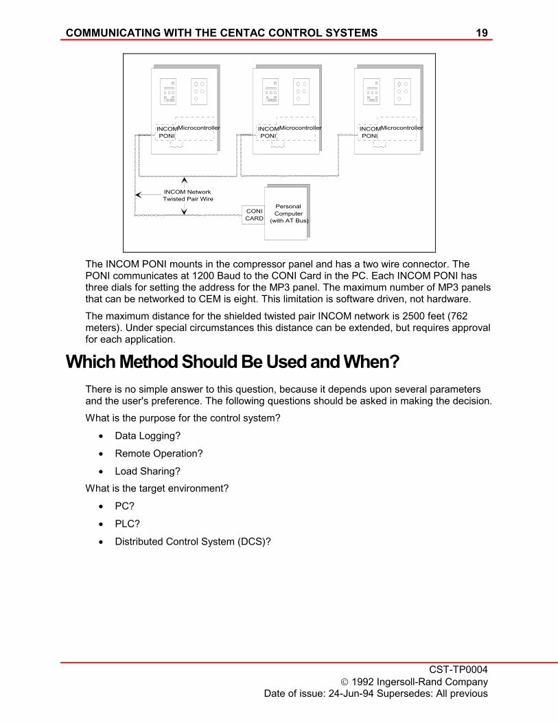
CEMThe Centac Energy Master requires an INCOM PONI for each compressor, twisted pairwire, and a PC with the AT bus structure and one empty 8-bit slot for the CONI Card.
COMMUNICATING WITH THE CENTAC CONTROL SYSTEMS 19
CST-TP0004� 1992 Ingersoll-Rand Company
Date of issue: 24-Jun-94 Supersedes: All previous
The INCOM PONI mounts in the compressor panel and has a two wire connector. ThePONI communicates at 1200 Baud to the CONI Card in the PC. Each INCOM PONI hasthree dials for setting the address for the MP3 panel. The maximum number of MP3 panelsthat can be networked to CEM is eight. This limitation is software driven, not hardware.The maximum distance for the shielded twisted pair INCOM network is 2500 feet (762meters). Under special circumstances this distance can be extended, but requires approvalfor each application.
Which Method Should Be Used and When?There is no simple answer to this question, because it depends upon several parametersand the user's preference. The following questions should be asked in making the decision.What is the purpose for the control system?
� Data Logging?
� Remote Operation?
� Load Sharing?What is the target environment?
� PC?
� PLC?
� Distributed Control System (DCS)?
PersonalComputer
(with AT Bus)
INCOM NetworkTwisted Pair Wire
MicrocontrollerINCOMPONI
MicrocontrollerINCOMPONI
MicrocontrollerINCOMPONI
CONICARD

20 COMMUNICATING WITH CENTAC CONTROL SYSTEMS
CST-TP0004� 1992 Ingersoll-Rand CompanyDate of issue: 24-Jun-94 Supersedes: All previous
If the target environment is a PLC or DCS system, does it have support for a serialinterface?Is other equipment (pumps, dryers, other compressors) involved in a centralized system?How many compressors are to be operated in the control system?What is the physical distance between the compressor(s) and the centralized system?
� feet (meters)?
� miles (kilometers)?Does the customer have resources or willing to write an interface and/or application?
Communication Features
FeaturesRS-232CInterface CEM
Software Written By Customer IR
Maximum Devices to Control 4095 8
Device Types SupportedMP3 Yes YesMVP Yes No
Unmanned Operation Yes Yes
MP3 Faceplate Control and Monitoring FunctionsCompressor Alert and Shutdown Status Yes* YesRun Time Yes* YesNumber of Starts Yes* YesStop Yes* YesReset Yes* YesAcknowledge Yes* YesStart Yes* YesActual Values Yes* YesAlert Values Yes* YesShutdown Values Yes* YesUnload Yes* YesModulate Yes* YesAutodual Yes* YesBypass Valve Status Yes* YesInlet Valve Status Yes* YesChange Set Points Yes* Yes

COMMUNICATING WITH THE CENTAC CONTROL SYSTEMS 21
CST-TP0004� 1992 Ingersoll-Rand Company
Date of issue: 24-Jun-94 Supersedes: All previous
FeaturesRS-232CInterface CEM
Other MP3 FunctionsControlled Surge Reset and Reload No YesCompressor Rotation No YesAutomatic Timed Logging of Compressor Data No YesEvent Logging of Trip, Alert, and Surge No YesLoad Sharing No YesAdaptation to Compressor Loading Schedule No YesSchedule Sequence Rotation of Compressors No Yes
MVP Faceplate Control and Monitoring FunctionsCompressor Alert and Shutdown Status Yes* NoStart Yes* NoStop Yes* NoLoad Yes* NoUnload Yes* NoReset Yes* NoCompressor Status Flags Yes* NoAnalog Buffer Yes* NoSetpoint Buffer Yes* NoChange Setpoints Yes* No
� Feature directly supported through interface software.
NOTE
"No" is not a physical limitation, but one imposed by the application software.Programming is required to achieve a "Yes".
GlossaryASCII American Standard Code for Information Interchange.
Byte Eight bits of data.
DCS Distributed Control System. A centralized system for controllingvarious types of equipment; i.e., compressors, pumps, dryers, etc.
EPROM Erasable Programmable Read Only Memory.
ERAM Erasable Random Access Memory.

22 COMMUNICATING WITH CENTAC CONTROL SYSTEMS
CST-TP0004� 1992 Ingersoll-Rand CompanyDate of issue: 24-Jun-94 Supersedes: All previous
INCOM INdustrial COMmunications Network. A Westinghouse dataprotocol.
INCOM Device Can be one of the following communication devices that have thecapability of translating the Westinghouse INCOM protocol into theRS-232C protocol. The current devices available are MINT, RS-232PONI, and a PONI Modem.
INCOM PONI Product Operated Network Interface.
MINT Master INCOM Network Translator. A networking device allowsinput of 4095 devices that transmit the INCOM signal andtranslates the signal into an RS-232C formatted signal.
Modem PONI Same as a PONI except with a telephone jack interface instead oftwisted pair wire interface.
MP3 Ingersoll-Rand microprocessor that provides the control andmonitoring for standard Centac air compressors.
MVP Specialized Ingersoll-Rand microprocessor that provides the controland monitoring for Centac models CV0 and CH3 air compressors.
Nibble Half of a byte, or four bits of data.
PROM Programmable Read Only Memory.
RAM Random Access Memory.
RS-232 PONI Product Operated Network Interface. A device that translates theINCOM signal into an RS-232C formatted signal.
Serial Device A Personal Computer (PC), Programmable Logic Controller (PLC),Distributed Control System (DCS) or any other device that cantransmit, receive and interpret an RS-232C formatted signal.
System Pressure The actual operating discharge pressure of the compressor.
Word Two bytes, or sixteen bits of data.


![Instruction Manual for Ku-band GaN 25W BUC [NJT8370 series] · 2019-03-03 · * Pin G: RS-232C TxD and Pin H: RS-232C RxD are available for only RS-232C Interface M&C models. * Do](https://img.dokumen.tips/doc/110x75/5e98d9fb511fe222e63bf374/instruction-manual-for-ku-band-gan-25w-buc-njt8370-series-2019-03-03-pin-g.jpg)


