Embed Size (px)
Citation preview

eCPRI presentation
© 2017 Ericsson AB, Huawei Technologies Co. Ltd, NEC Corporation and Nokia.
Common Public Radio Interface
Background 1/21. Operator view of CPRI features
Although CPRI has been the main Fronthaul interface standard, many operators started to question its suitability to high bandwidth 5G use cases.
Improvements to efficiency and link capacity utilization were requested.
Also advanced networking and OAM features of mainstream packet transport standards were requested.
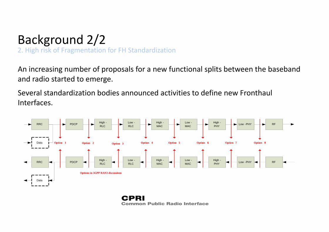
Background 2/22. High risk of Fragmentation for FH Standardization
An increasing number of proposals for a new functional splits between the baseband and radio started to emerge.
Several standardization bodies announced activities to define new Fronthaul Interfaces.
PDCP Low -RLC
High -MAC
Low -MAC
High -PHY
Low -PHY
PDCPLow -RLC
High -MAC
Low -MAC
High -PHY Low -PHY
Option 54 Option 6 Option 7Option 2Option 1
RRC
RRC
RF
RF
Option 8
Data
Data
High -RLC
High -RLC
Option 3 Option
Options in 3GPP RAN3 discussions
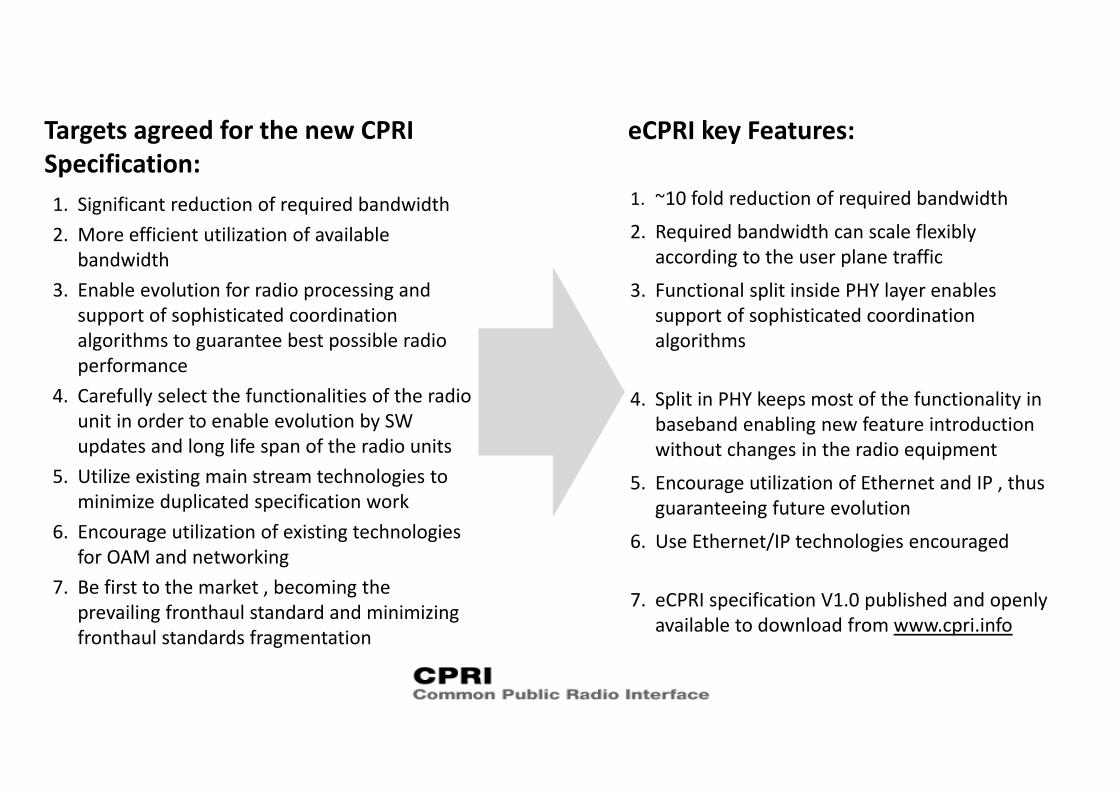
Targets agreed for the new CPRI Specification:1. Significant reduction of required bandwidth2. More efficient utilization of available
bandwidth3. Enable evolution for radio processing and
support of sophisticated coordination algorithms to guarantee best possible radio performance
4. Carefully select the functionalities of the radio unit in order to enable evolution by SW updates and long life span of the radio units
5. Utilize existing main stream technologies to minimize duplicated specification work
6. Encourage utilization of existing technologies for OAM and networking
7. Be first to the market , becoming the prevailing fronthaul standard and minimizing fronthaul standards fragmentation
1. ~10 fold reduction of required bandwidth
2. Required bandwidth can scale flexibly according to the user plane traffic
3. Functional split inside PHY layer enables support of sophisticated coordination algorithms
4. Split in PHY keeps most of the functionality in baseband enabling new feature introduction without changes in the radio equipment
5. Encourage utilization of Ethernet and IP , thus guaranteeing future evolution
6. Use Ethernet/IP technologies encouraged
7. eCPRI specification V1.0 published and openly available to download from www.cpri.info
eCPRI key Features:
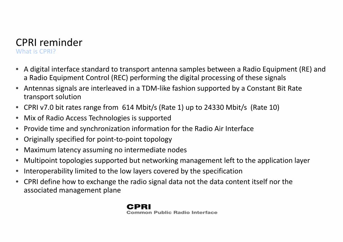
What is CPRI?CPRI reminder
• A digital interface standard to transport antenna samples between a Radio Equipment (RE) and a Radio Equipment Control (REC) performing the digital processing of these signals
• Antennas signals are interleaved in a TDM‐like fashion supported by a Constant Bit Rate transport solution
• CPRI v7.0 bit rates range from 614 Mbit/s (Rate 1) up to 24330 Mbit/s (Rate 10)• Mix of Radio Access Technologies is supported• Provide time and synchronization information for the Radio Air Interface• Originally specified for point‐to‐point topology• Maximum latency assuming no intermediate nodes• Multipoint topologies supported but networking management left to the application layer• Interoperability limited to the low layers covered by the specification • CPRI define how to exchange the radio signal data not the data content itself nor the
associated management plane
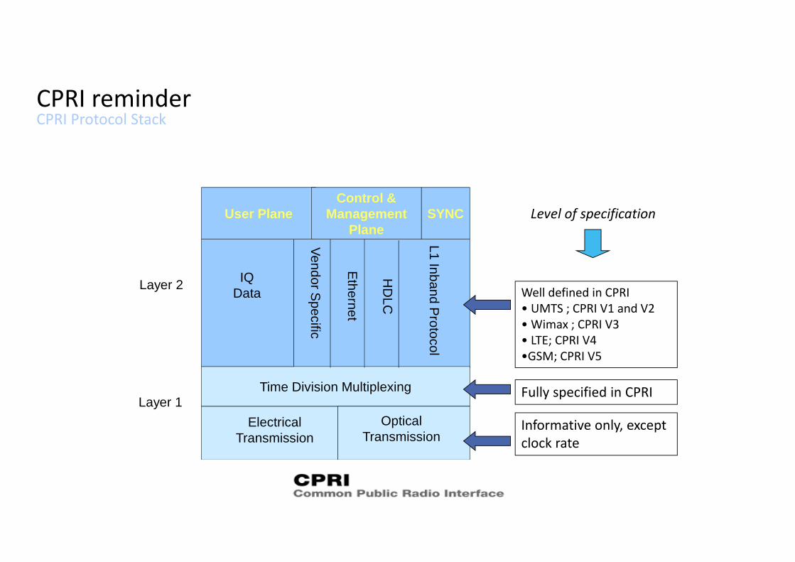
CPRI Protocol StackCPRI reminder
Time Division Multiplexing
User PlaneControl &
ManagementPlane
ElectricalTransmission
OpticalTransmission
IQData
Ethernet
HD
LC
L1 Inband Protocol
Vendor Specific
Layer 1
Layer 2
SYNC
Well defined in CPRI• UMTS ; CPRI V1 and V2• Wimax ; CPRI V3• LTE; CPRI V4•GSM; CPRI V5
Fully specified in CPRI
Informative only, except clock rate
Level of specification
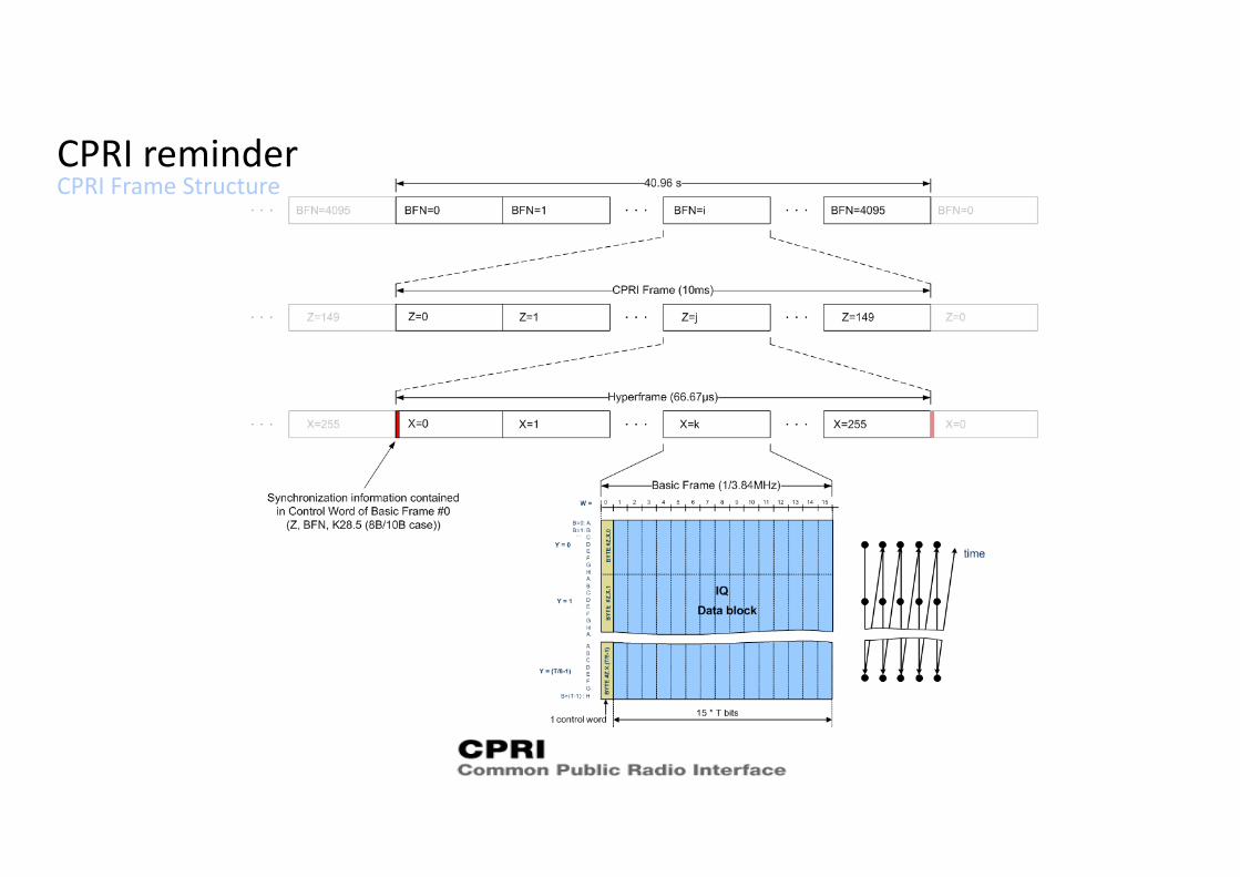
CPRI Frame StructureCPRI reminder
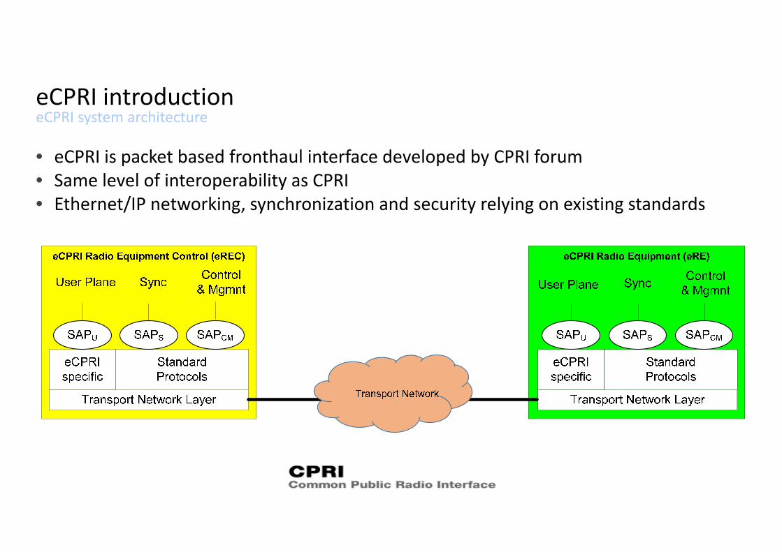
eCPRI system architectureeCPRI introduction
• eCPRI is packet based fronthaul interface developed by CPRI forum• Same level of interoperability as CPRI• Ethernet/IP networking, synchronization and security relying on existing standards
eCPRI main characteristicseCPRI introduction
• eCPRI does not constrain the use of specific network‐ and data link‐layer protocols to form the network• Any type of network can be used for eCPRI, provided eCPRI requirements are fulfilled.• “Requirements for the eCPRI Transport Network” aim to ensure that eCPRI systems can:
• Use packet based transport network solutions• Comply with the requirements associated with the more stringent radio technologies
features in terms of: • Timing and frequency accuracy• Bandwidth capacity,• …
• eCPRI also encourages the use of existing de‐facto/de‐jure standard protocols as much as possible where available
• In case eCPRI User Plane over Ethernet directly, eCPRI messages shall be transmitted in standard Ethernet frames. The type field of the Ethernet frame shall contain the eCPRI Ethertype (AEFE16)
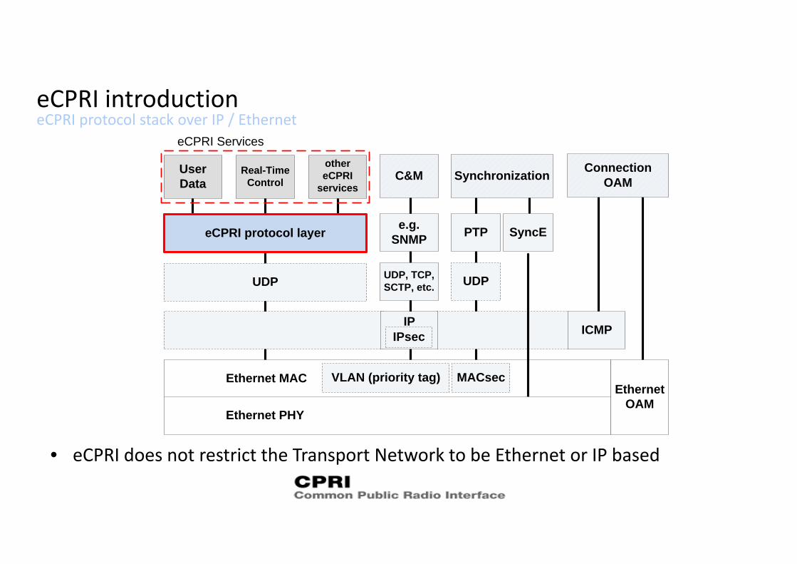
eCPRI protocol stack over IP / Ethernet eCPRI introduction
• eCPRI does not restrict the Transport Network to be Ethernet or IP based
Ethernet MAC
UDP
eCPRI protocol layer
User Data
Real-Time Control
eCPRI Services
UDP, TCP, SCTP, etc.
e.g. SNMP PTP
C&M Synchronizationother eCPRI
services
UDP
ConnectionOAM
Ethernet OAM
IP ICMP
MACsecVLAN (priority tag)
IPsec
SyncE
Ethernet PHY
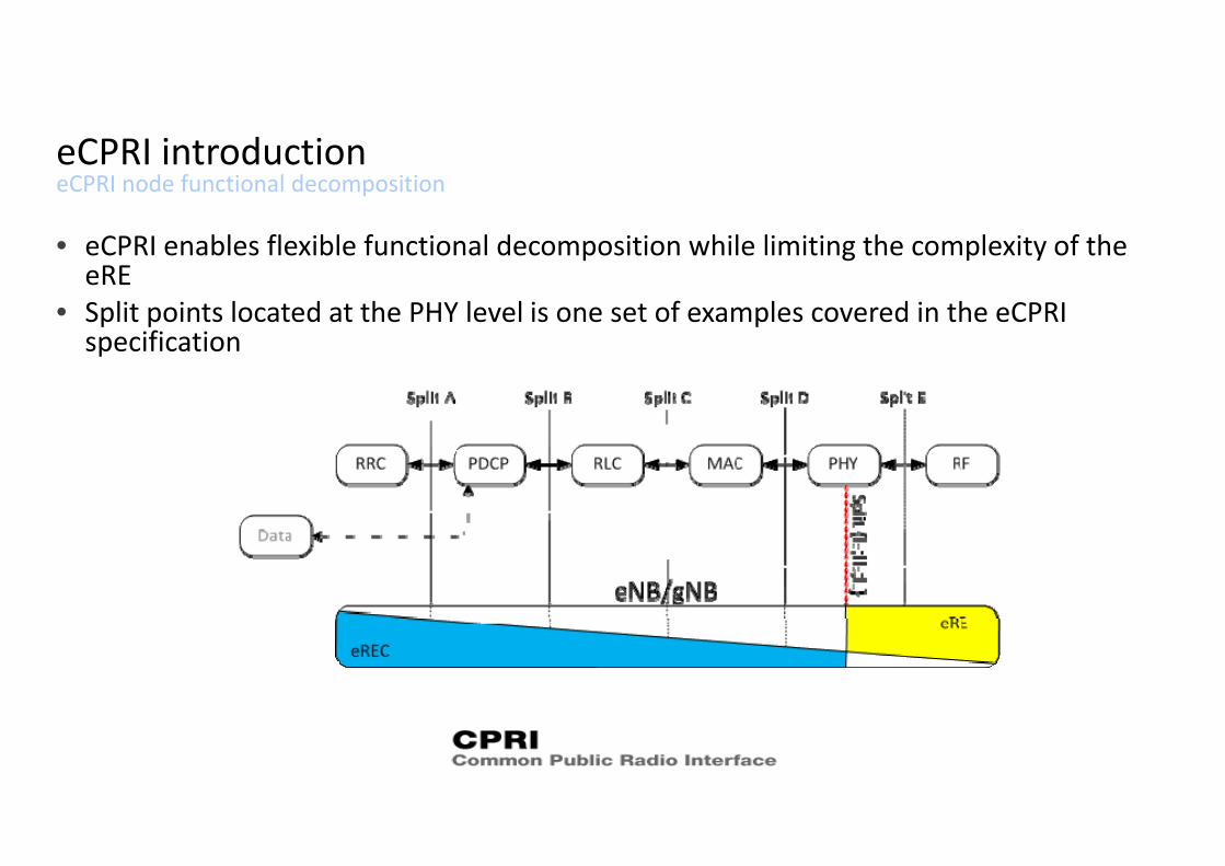
eCPRI node functional decompositioneCPRI introduction
• eCPRI enables flexible functional decomposition while limiting the complexity of the eRE
• Split points located at the PHY level is one set of examples covered in the eCPRI specification
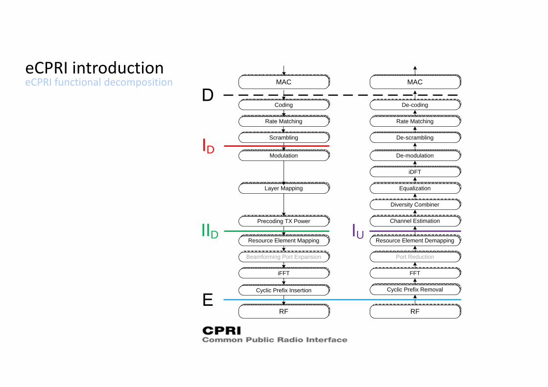
eCPRI functional decompositioneCPRI introduction
MAC
Coding
Rate Matching
Scrambling
Modulation
Layer Mapping
Precoding TX Power
Resource Element Mapping
iFFT
Cyclic Prefix Insertion
RF
MAC
Rate Matching
De-scrambling
De-modulation
iDFT
Resource Element Demapping
FFT
Cyclic Prefix Removal
RF
De-coding
D
D
Port Reduction
Channel Estimation
Diversity Combiner
Equalization
Beamforming Port Expansion
U
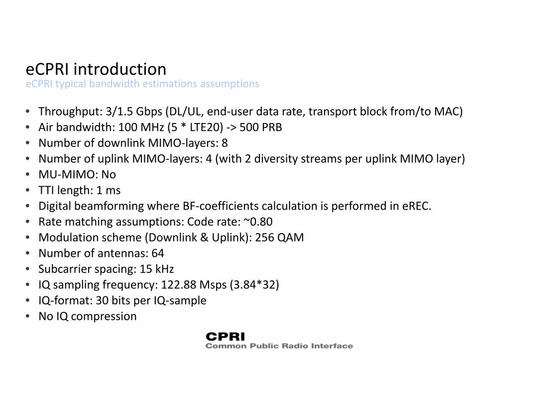
eCPRI typical bandwidth estimations assumptionseCPRI introduction
• Throughput: 3/1.5 Gbps (DL/UL, end‐user data rate, transport block from/to MAC)• Air bandwidth: 100 MHz (5 * LTE20) ‐> 500 PRB• Number of downlink MIMO‐layers: 8• Number of uplink MIMO‐layers: 4 (with 2 diversity streams per uplink MIMO layer)• MU‐MIMO: No• TTI length: 1 ms• Digital beamforming where BF‐coefficients calculation is performed in eREC.• Rate matching assumptions: Code rate: ~0.80• Modulation scheme (Downlink & Uplink): 256 QAM• Number of antennas: 64• Subcarrier spacing: 15 kHz• IQ sampling frequency: 122.88 Msps (3.84*32)• IQ‐format: 30 bits per IQ‐sample• No IQ compression
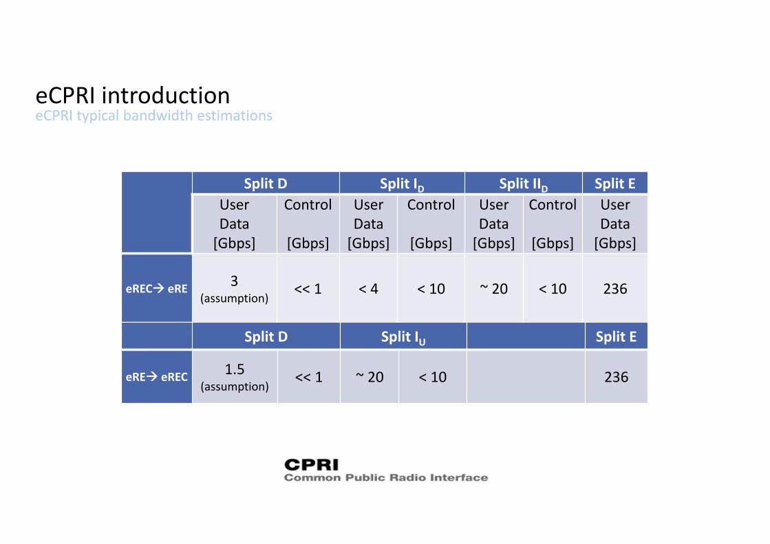
eCPRI typical bandwidth estimationseCPRI introduction
Split D Split ID Split IID Split EUserData[Gbps]
Control
[Gbps]
User Data[Gbps]
Control
[Gbps]
User Data[Gbps]
Control
[Gbps]
User Data[Gbps]
eREC eRE 3 (assumption)
<< 1 < 4 < 10 ~ 20 < 10 236
Split D Split IU Split E
eRE eREC 1.5 (assumption)
<< 1 ~ 20 < 10 236
eCPRI Messages Common Header formateCPRI User Plane messages
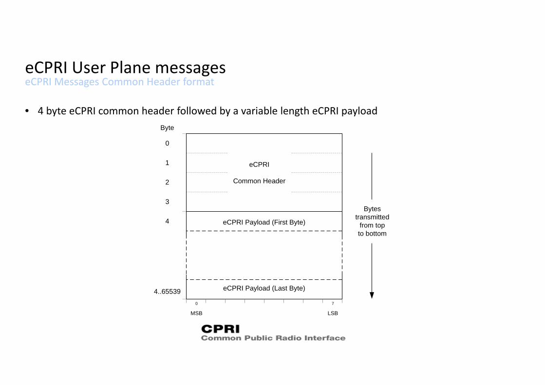
• 4 byte eCPRI common header followed by a variable length eCPRI payload
eCPRI Payload (First Byte)
eCPRI Payload (Last Byte)
MSB LSB
0 7
4..65539
Byte
2
1
0
3
4
eCPRI
Common Header
Bytestransmitted
from topto bottom
eCPRI Messages Common Header formateCPRI User Plane messages
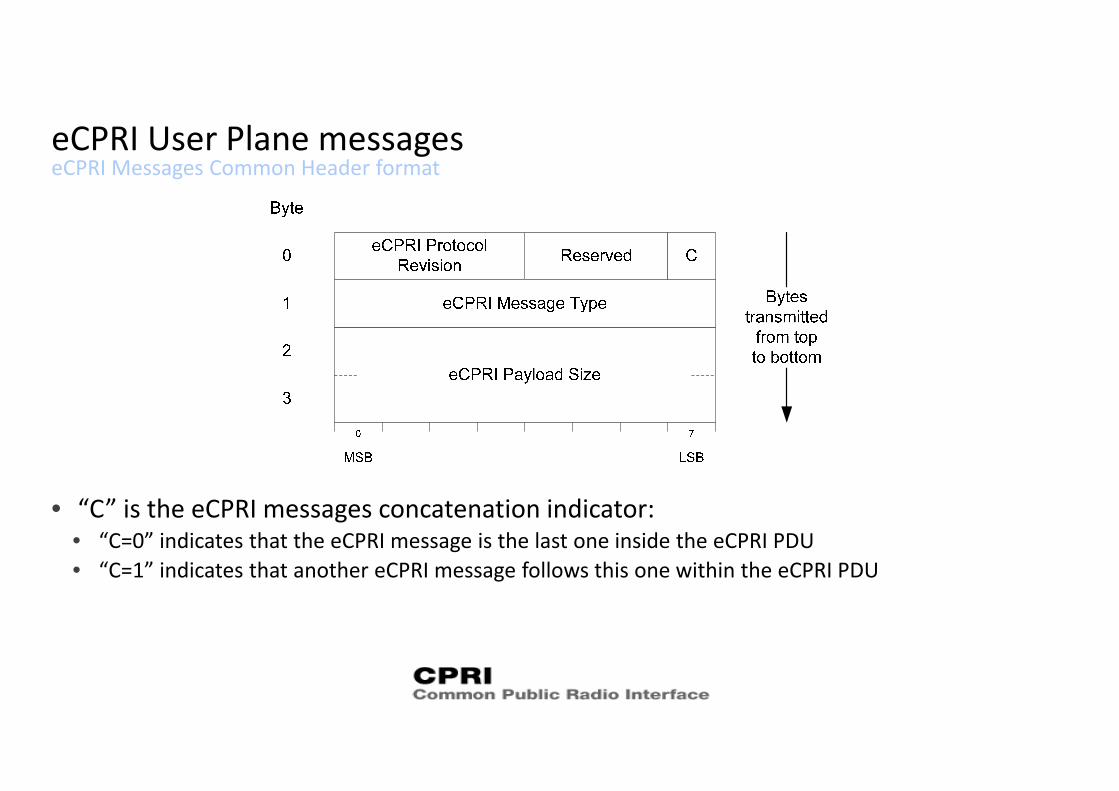
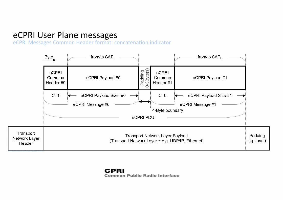
• “C” is the eCPRI messages concatenation indicator:• “C=0” indicates that the eCPRI message is the last one inside the eCPRI PDU• “C=1” indicates that another eCPRI message follows this one within the eCPRI PDU
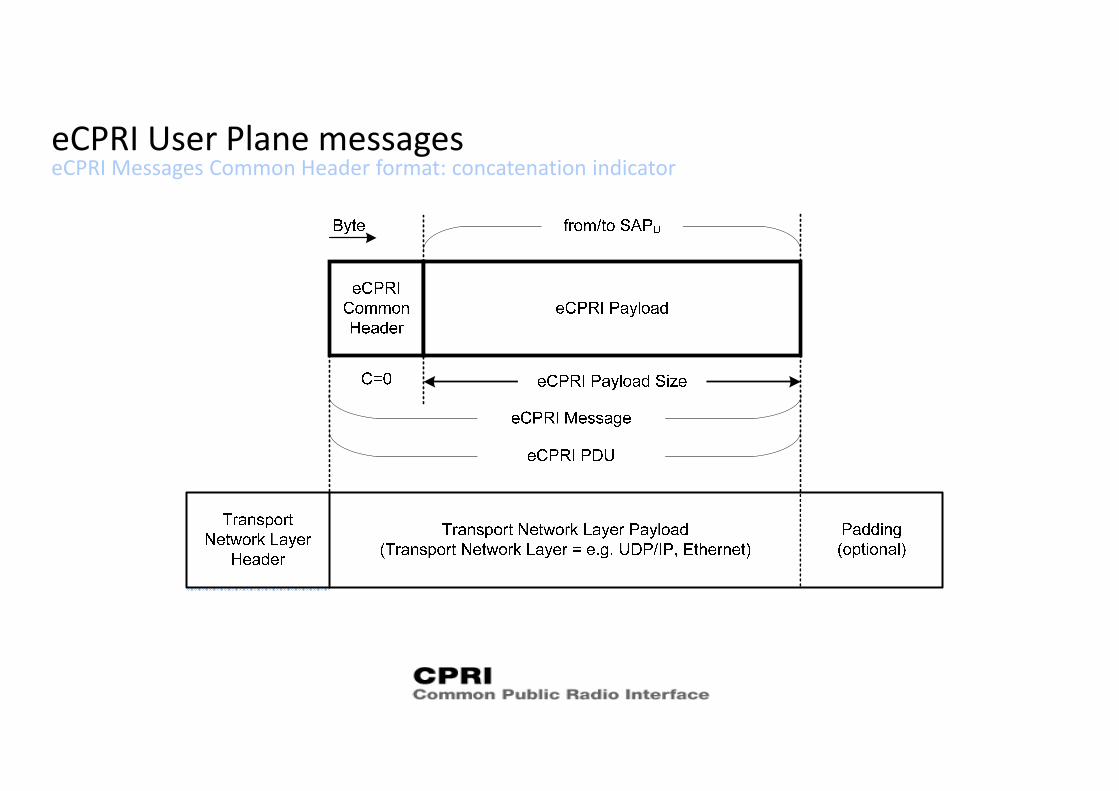
eCPRI Messages Common Header format: concatenation indicatoreCPRI User Plane messages
eCPRI Messages Common Header format: concatenation indicatoreCPRI User Plane messages
Padd
ing
0-3B
yte(
s)
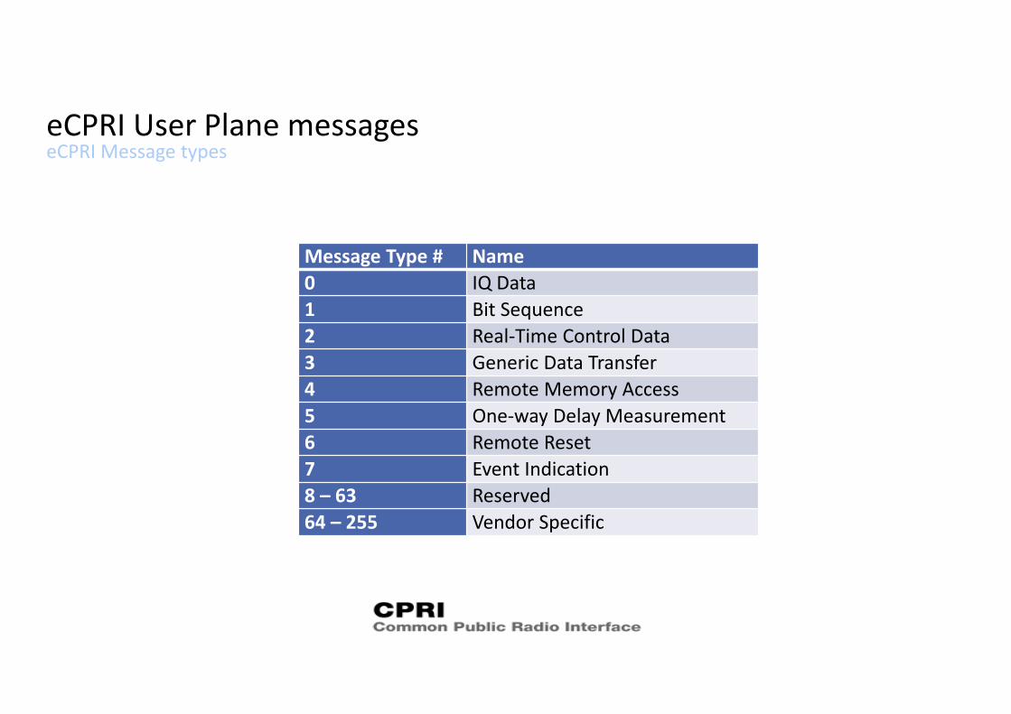
eCPRI Message typeseCPRI User Plane messages
Message Type # Name0 IQ Data1 Bit Sequence2 Real‐Time Control Data3 Generic Data Transfer4 Remote Memory Access5 One‐way Delay Measurement6 Remote Reset7 Event Indication8 – 63 Reserved64 – 255 Vendor Specific
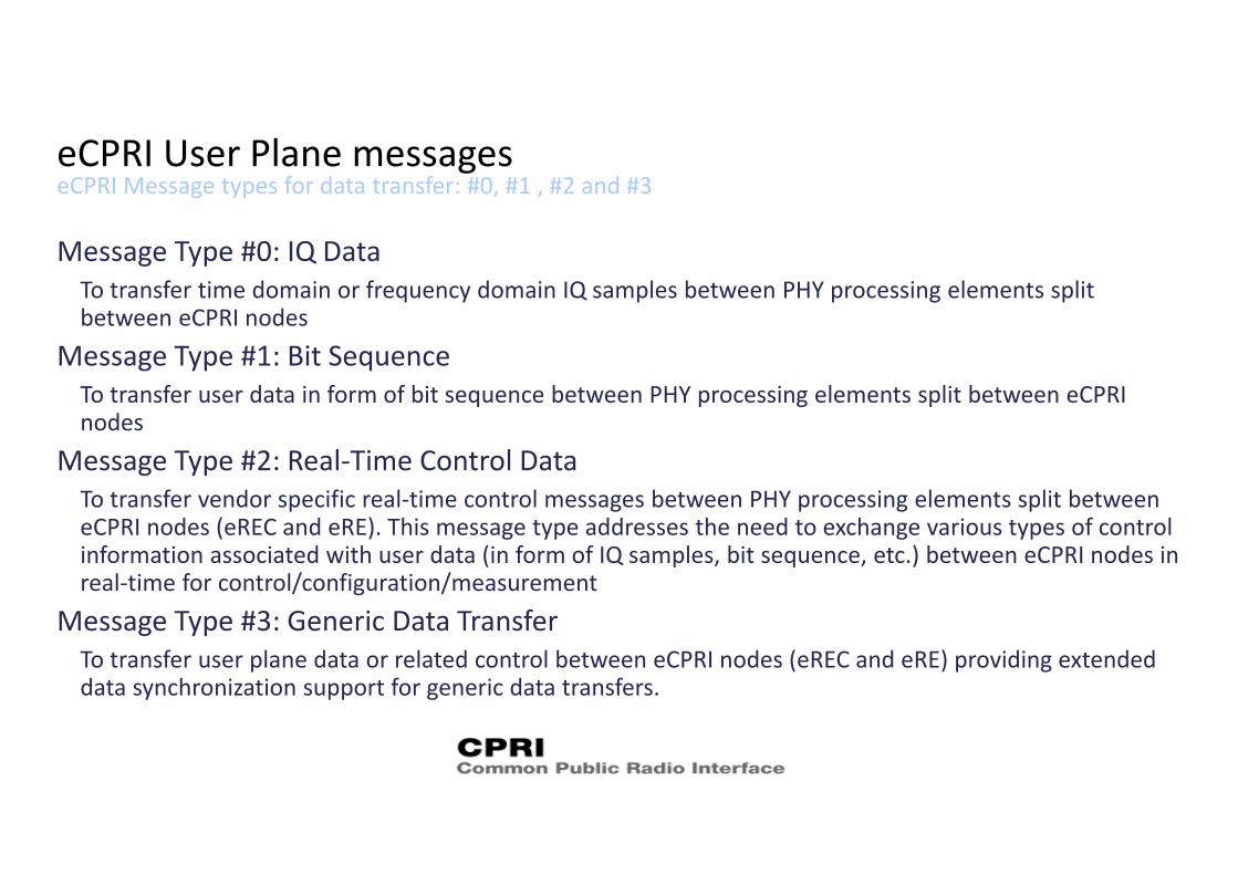
eCPRI Message types for data transfer: #0, #1 , #2 and #3eCPRI User Plane messages
Message Type #0: IQ DataTo transfer time domain or frequency domain IQ samples between PHY processing elements split between eCPRI nodes
Message Type #1: Bit SequenceTo transfer user data in form of bit sequence between PHY processing elements split between eCPRI nodes
Message Type #2: Real‐Time Control DataTo transfer vendor specific real‐time control messages between PHY processing elements split between eCPRI nodes (eREC and eRE). This message type addresses the need to exchange various types of control information associated with user data (in form of IQ samples, bit sequence, etc.) between eCPRI nodes in real‐time for control/configuration/measurement
Message Type #3: Generic Data TransferTo transfer user plane data or related control between eCPRI nodes (eREC and eRE) providing extended data synchronization support for generic data transfers.
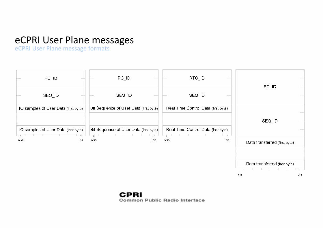
eCPRI User Plane message formatseCPRI User Plane messages
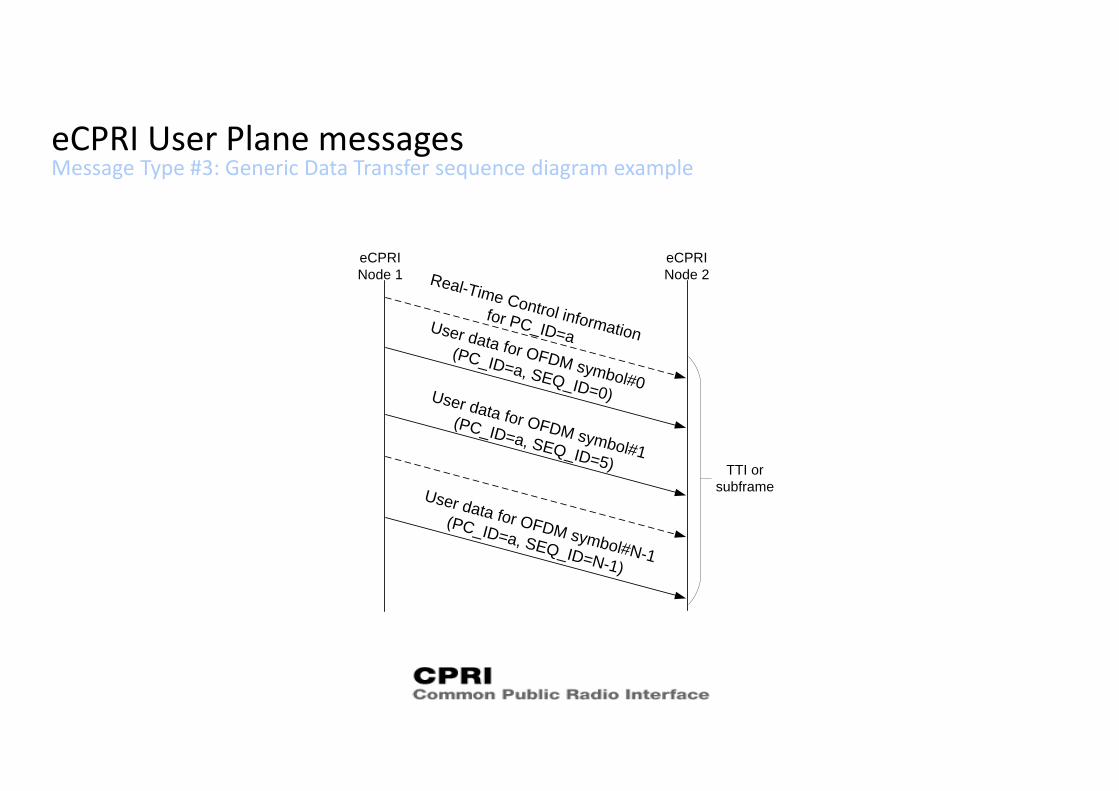
Message Type #3: Generic Data Transfer sequence diagram exampleeCPRI User Plane messages
eCPRINode 1
eCPRINode 2Real-Time Control information
for PC_ID=a
TTI orsubframe
User data for OFDM symbol#0
(PC_ID=a, SEQ_ID=0)User data for OFDM symbol#1
(PC_ID=a, SEQ_ID=5)
User data for OFDM symbol#N-1
(PC_ID=a, SEQ_ID=N-1)
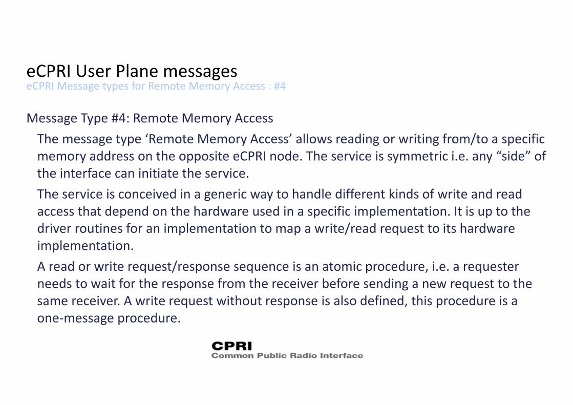
eCPRI Message types for Remote Memory Access : #4eCPRI User Plane messages
Message Type #4: Remote Memory AccessThe message type ‘Remote Memory Access’ allows reading or writing from/to a specific memory address on the opposite eCPRI node. The service is symmetric i.e. any “side” of the interface can initiate the service.The service is conceived in a generic way to handle different kinds of write and read access that depend on the hardware used in a specific implementation. It is up to the driver routines for an implementation to map a write/read request to its hardware implementation.A read or write request/response sequence is an atomic procedure, i.e. a requester needs to wait for the response from the receiver before sending a new request to the same receiver. A write request without response is also defined, this procedure is a one‐message procedure.
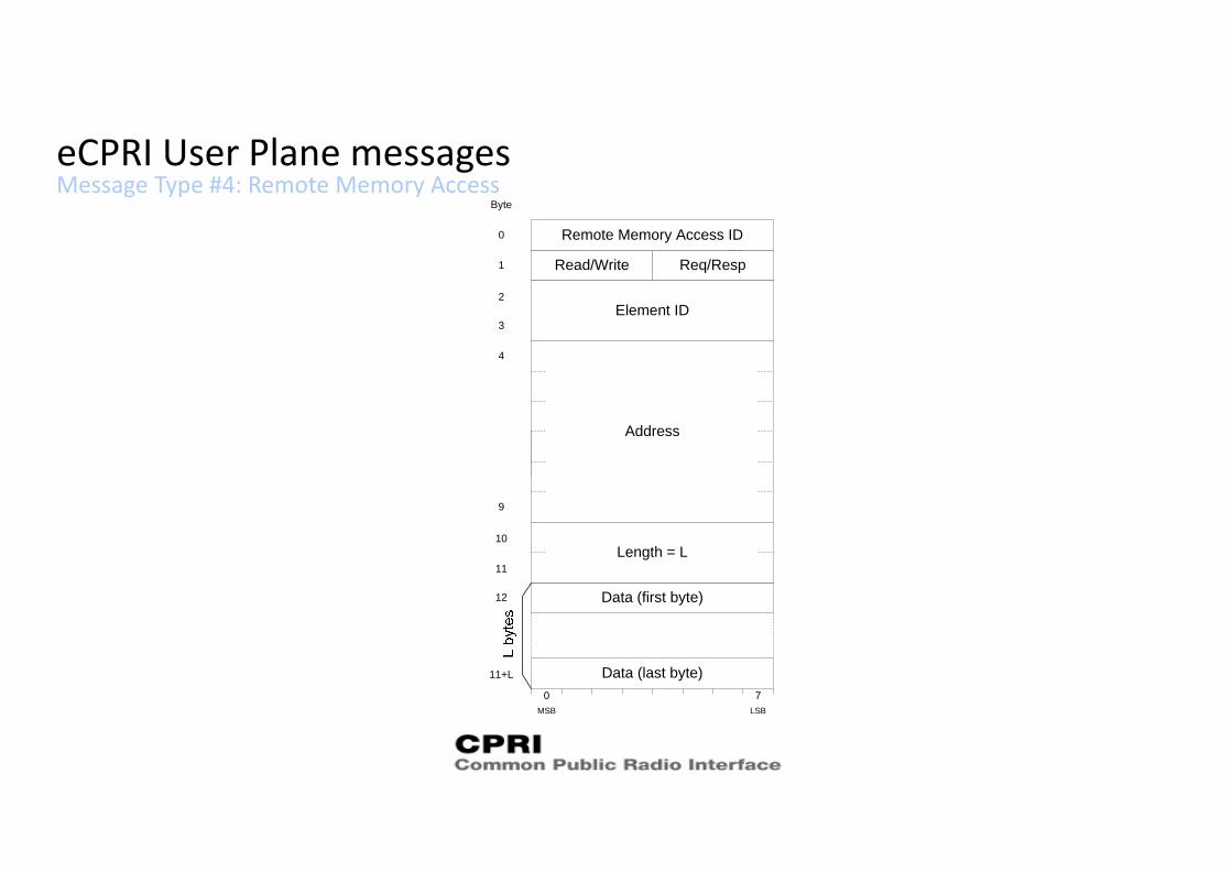
Message Type #4: Remote Memory AccesseCPRI User Plane messages
Address
MSB LSB
0 7
Data (last byte)
Data (first byte)
11+L
Byte
9
Req/RespRead/Write
0
1
Remote Memory Access ID
Length = L10
Element ID2
3
4
11
12
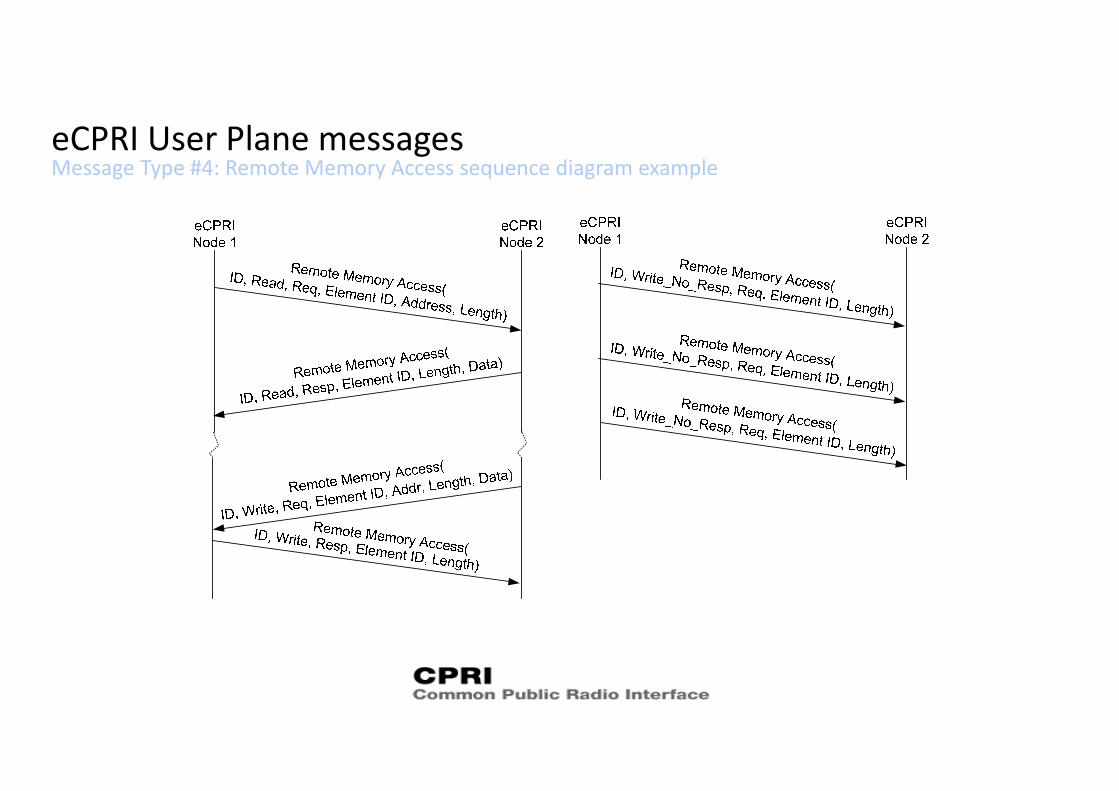
Message Type #4: Remote Memory Access sequence diagram exampleeCPRI User Plane messages
eCPRI Message types for One‐Way Delay Measurement: #5eCPRI User Plane messages
Message Type #5: One‐Way Delay MeasurementThe message type ‘One‐Way delay measurement’ is used for estimating the one‐way delay between two eCPRI‐ports in one direction. The one‐way delay measurement can be performed without or with a Follow_Up message (1‐Step and 2‐Step versions). The decision of which version to use is vendor specific.
The service assumes that both nodes are time synchronized to a common time with an accuracy sufficient for the eCPRI service.
The usage of eCPRI message type ‘One‐Way delay measurement’ regarding which node initiates a transmission, the frequency of measurements, response deadline, etc. is vendor specific.
eCPRI Message types for One‐Way Delay Measurement: #5eCPRI User Plane messages
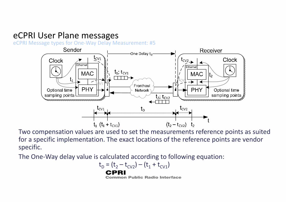
Two compensation values are used to set the measurements reference points as suited for a specific implementation. The exact locations of the reference points are vendor specific.The One‐Way delay value is calculated according to following equation:
tD = (t2 – tCV2) – (t1 + tCV1)
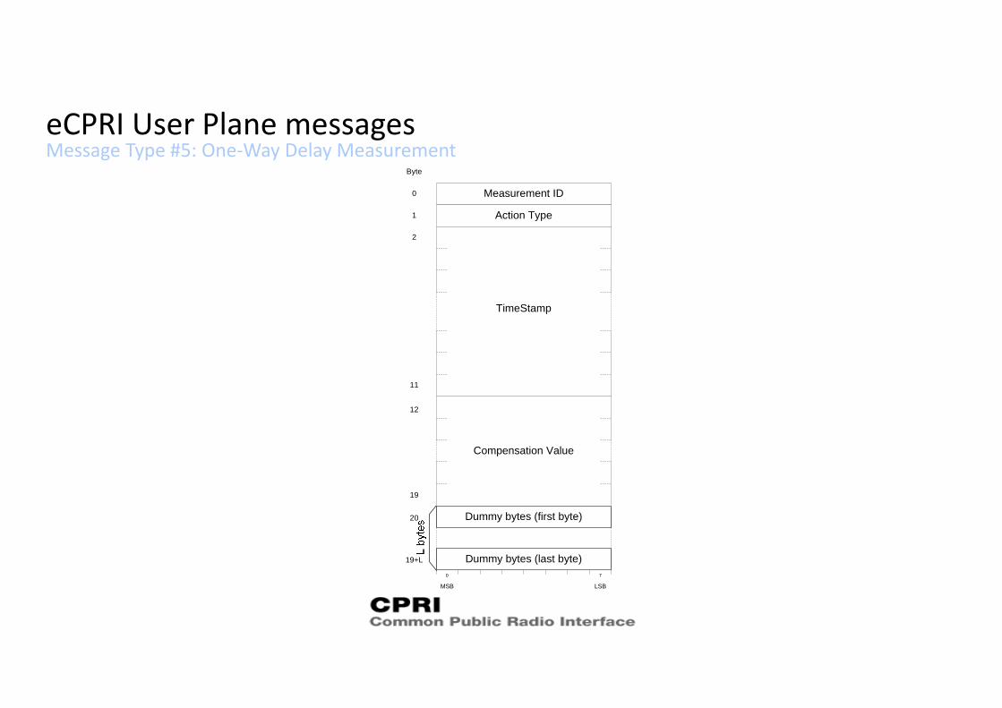
Message Type #5: One‐Way Delay MeasurementeCPRI User Plane messages
TimeStamp
MSB LSB
0 7
Dummy bytes (last byte)
Dummy bytes (first byte)
19+L
Byte
11
Action Type
0
1
Measurement ID
Compensation Value
19
2
12
20
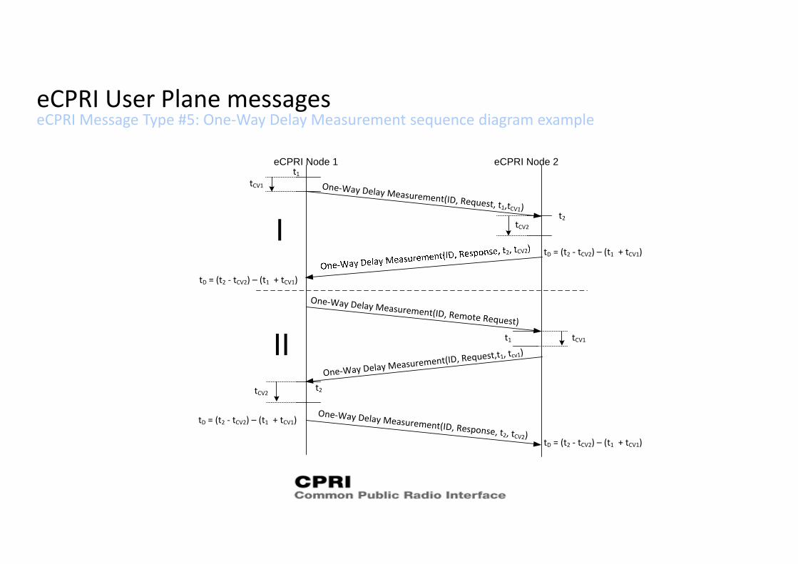
eCPRI Message Type #5: One‐Way Delay Measurement sequence diagram exampleeCPRI User Plane messages
eCPRI Node 1 eCPRI Node 2t1
tCV1
t2
One‐Way Delay Measurement(ID, Request, t1,tCV1)
tD = (t2 ‐ tCV2) – (t1 + tCV1)
tCV2
tD = (t2 ‐ tCV2) – (t1 + tCV1)
One‐Way Delay Measurement(ID, Remote Request)
tCV1
One‐Way Delay Measurement(ID, Request,t1, tcv1)
t2tCV2
t1
tD = (t2 ‐ tCV2) – (t1 + tCV1)
tD = (t2 ‐ tCV2) – (t1 + tCV1)
2 CV2
One‐Way Delay Measurement(ID, Response, t2, tCV2)
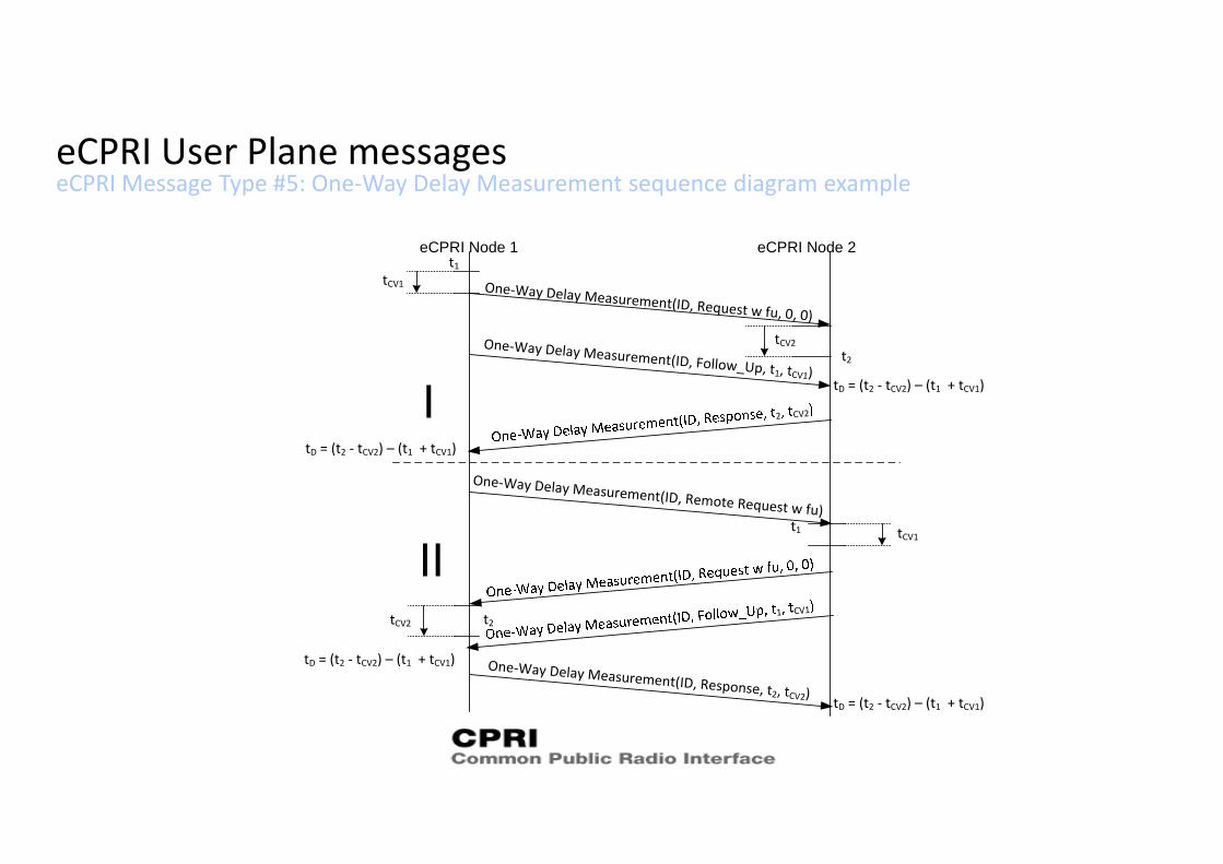
eCPRI Message Type #5: One‐Way Delay Measurement sequence diagram exampleeCPRI User Plane messages
eCPRI Node 1 eCPRI Node 2t1
tCV1
t2
One‐Way Delay Measurement(ID, Request w fu, 0, 0)
tD = (t2 ‐ tCV2) – (t1 + tCV1)
tCV2
tD = (t2 ‐ tCV2) – (t1 + tCV1)
One‐Way Delay Measurement(ID, Remote Request w fu)tCV1
t2tCV2
t1
tD = (t2 ‐ tCV2) – (t1 + tCV1)
tD = (t2 ‐ tCV2) – (t1 + tCV1)
One‐Way Delay Measurement(ID, Follow_Up, t1, tCV1)
2 CV2
1 CV1
One‐Way Delay Measurement(ID, Response, t2, tCV2)
eCPRI Message types for Remote Reset: #6eCPRI User Plane messages
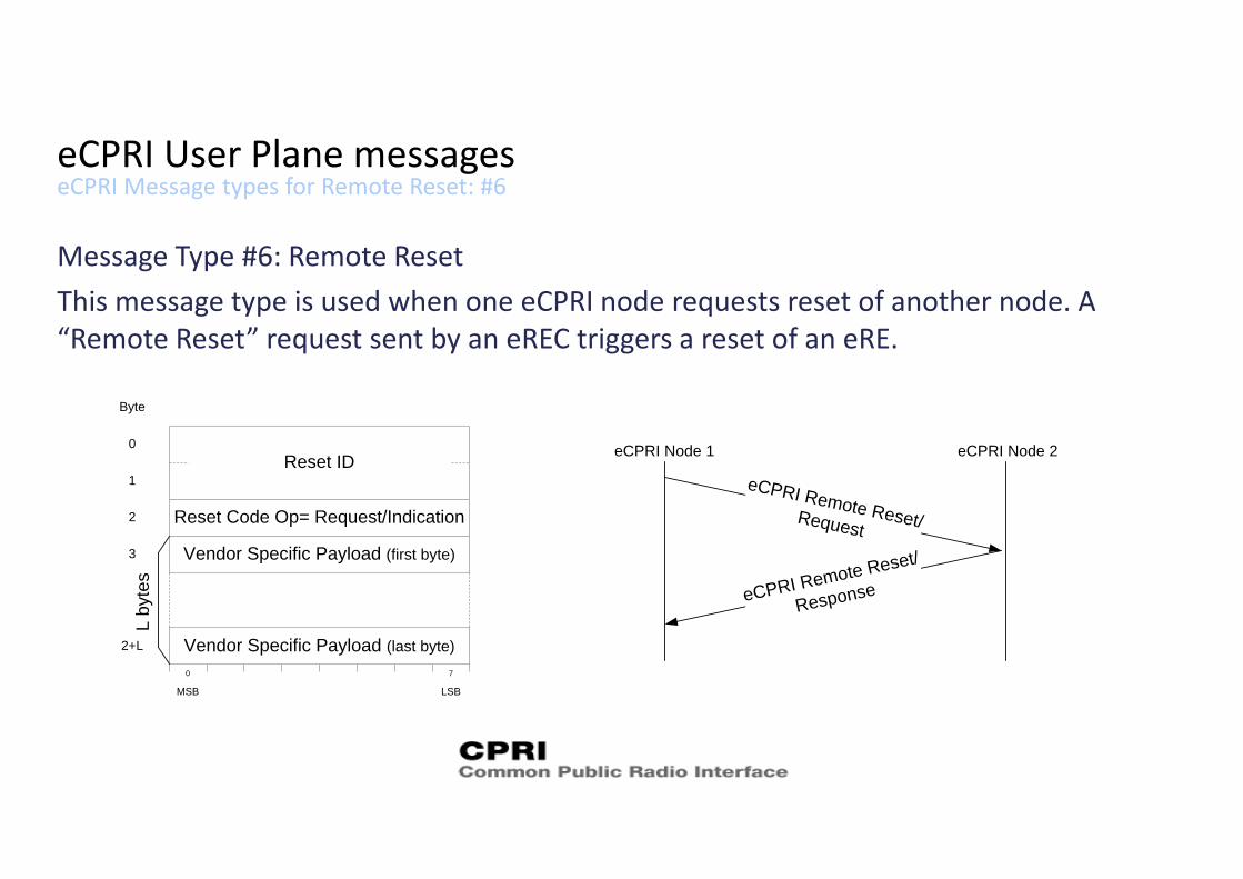
Message Type #6: Remote ResetThis message type is used when one eCPRI node requests reset of another node. A “Remote Reset” request sent by an eREC triggers a reset of an eRE.
Reset ID
Byte
0
2
1
Reset Code Op= Request/Indication
MSB LSB
0 7
Vendor Specific Payload (last byte)
Vendor Specific Payload (first byte)
2+L
3
Lby
tes
eCPRI Node 1 eCPRI Node 2
eCPRI Remote Reset/Request
eCPRI Remote Reset/
Response
eCPRI Message types for Event Indication: #7eCPRI User Plane messages
Message Type #7: Event IndicationThe message type ‘Event Indication’ is used when either side of the protocol indicates to the other end that an event has occurred. An event is either a raised or ceased fault or a notification. Transient faults shall be indicated with a Notification.Faults/Notifications sent on eCPRI level should be relevant to the eCPRI services. One Event Indication can either contain one or more faults, or one or more notifications. The Event/Fault Indication message could be sent from an eCPRI node at any time.An eCPRI node is modelled as consisting of N Elements, a fault or notification is connected to 1 Element. The detailed mapping of a specific implementation of HW and SW to Elements and their associated faults/notification is vendor specific.For consistency check a synchronization request procedure is defined.
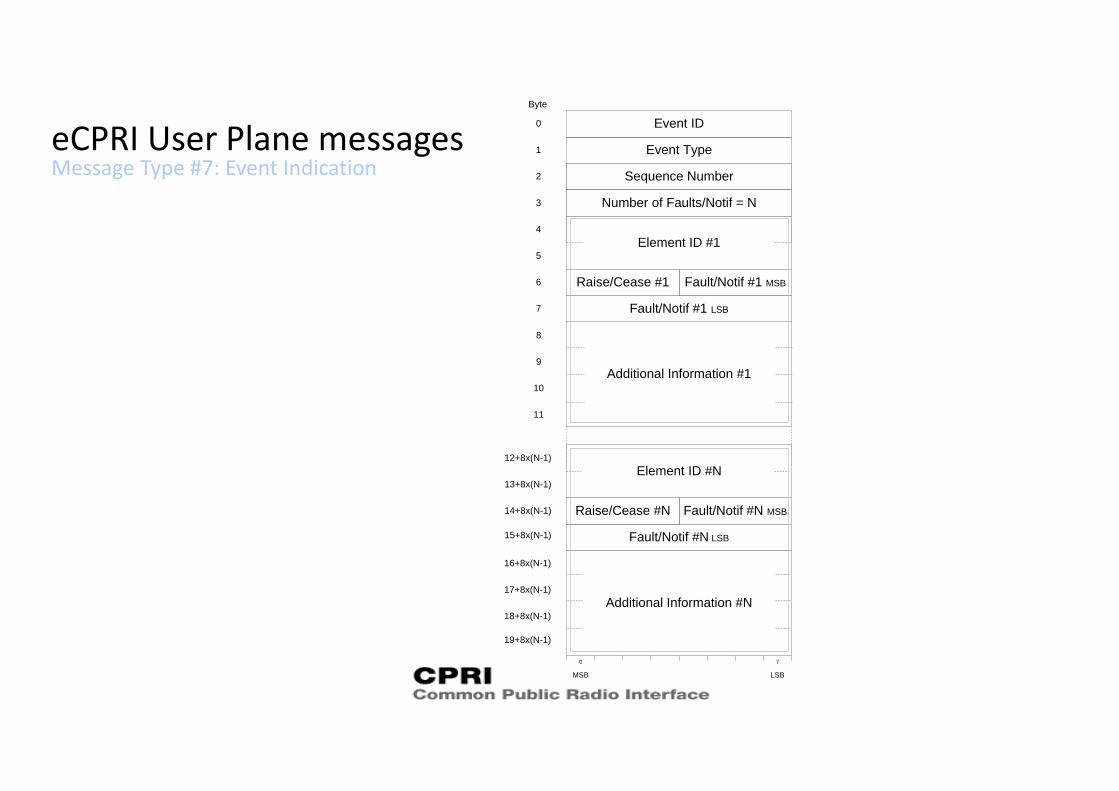
Message Type #7: Event IndicationeCPRI User Plane messages
MSB LSB
0 7
Byte
Event Type
0
1
Event ID
Sequence Number2
3 Number of Faults/Notif = N
Element ID #1
Fault/Notif #1 MSB
Fault/Notif #1 LSB
Raise/Cease #1
4
5
6
7
Fault/Notif #N MSB
Fault/Notif #N LSB
Raise/Cease #N
Element ID #N12+8x(N-1)
13+8x(N-1)
14+8x(N-1)
15+8x(N-1)
Additional Information #1
8
9
10
11
Additional Information #N
16+8x(N-1)
17+8x(N-1)
18+8x(N-1)
19+8x(N-1)
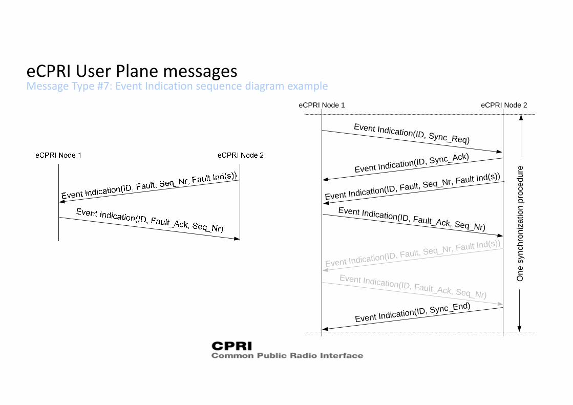
Message Type #7: Event Indication sequence diagram exampleeCPRI User Plane messages
eCPRI Node 1 eCPRI Node 2
Event Indication(ID, Sync_Req)
Event Indication(ID, Sync_Ack)
Event Indication(ID, Fault, Seq_Nr, Fault Ind(s))
Event Indication(ID, Fault_Ack, Seq_Nr)
Event Indication(ID, Fault, Seq_Nr, Fault Ind(s))
Event Indication(ID, Fault_Ack, Seq_Nr)
Event Indication(ID, Sync_End)
One
syn
chro
niza
tion
proc
edur
e
Control and Management Service Access pointeCPRI C&M
The C&M information will not be transmitted via the eCPRI specific protocol.The details of this information flow are out of the scope of the eCPRI specification.This information flow can use protocols (e.g. TCP) over the IP protocol but any othersolution is not precluded.
The C&M information flow will be considered as non‐time‐critical and utilize a small partof the total bandwidth between eCPRI entities.
The majority of this information flow will be considered as background traffic, the rest isinteractive traffic needed to keep control of the eCPRI node.The eCPRI specification highlights some considerations regarding relative priorities of thedifferent flows.
Synchronization Service Access pointeCPRI Synchronization
eCPRI nodes shall recover the synchronization and timing from a synchronizationreference source, and the air interface of the eRE shall meet the 3GPP synchronizationand timing requirements.
The synchronization information will not be transmitted via the eCPRI specific protocol.The details of this information flow are out of the scope of the eCPRI specification.This information flow can use protocols (e.g. SyncE, PTP) but any other solution is notprecluded.
The synchronization information flow will be considered as time‐critical and will utilize asmall part of the total bandwidth between eCPRI nodes.
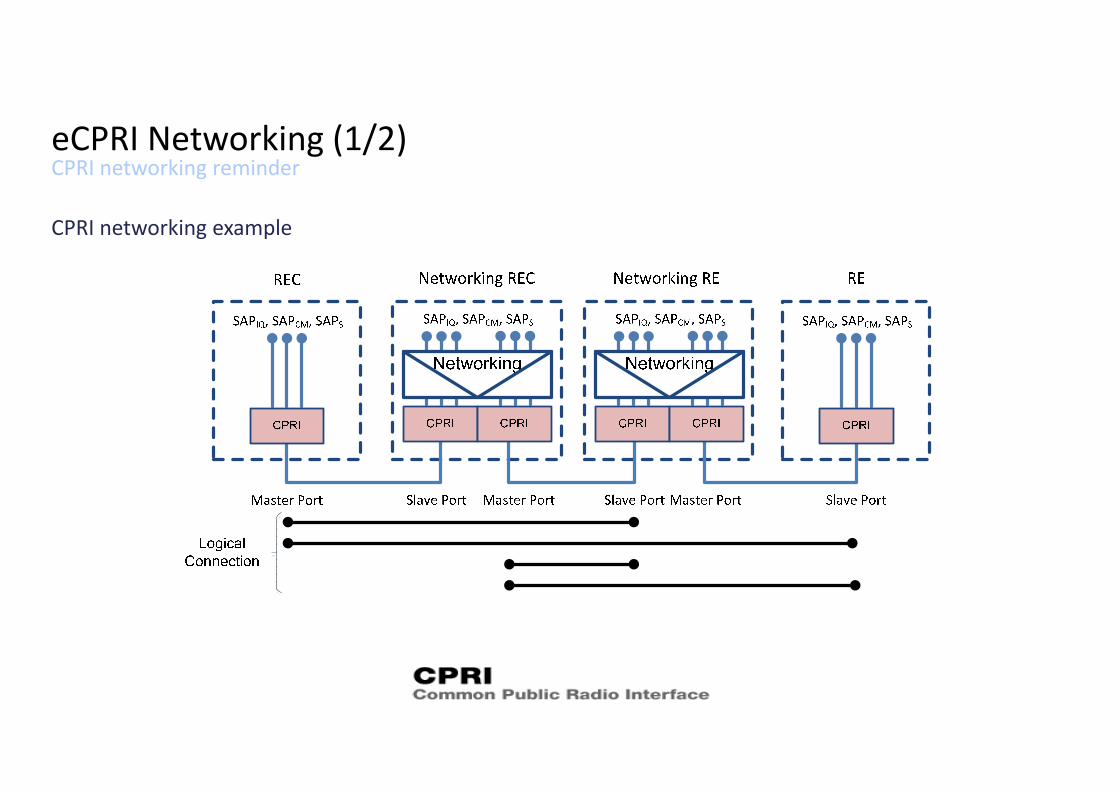
CPRI networking remindereCPRI Networking (1/2)
CPRI networking example
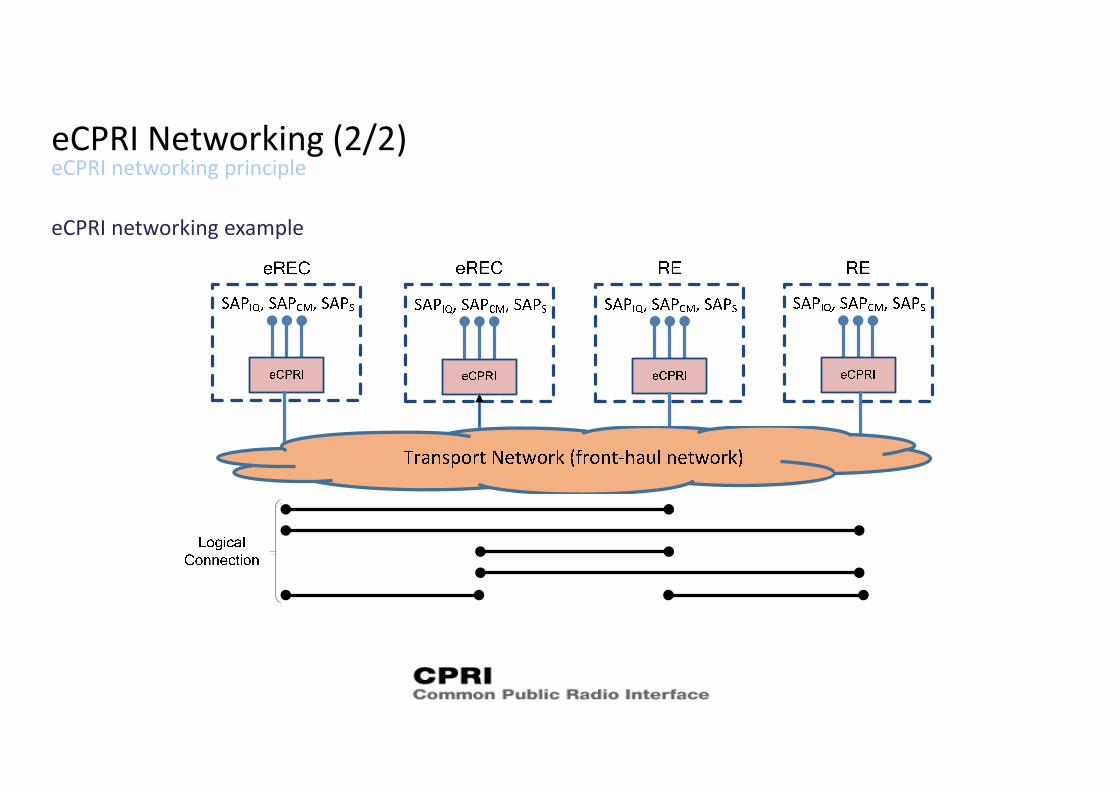
eCPRI networking principleeCPRI Networking (2/2)
eCPRI networking example