Embed Size (px)
Citation preview

Commissioning testing of a 1 MVA Superconducting transformer featuring 2G HTS Roebel cable
Glasson N, Staines M, Allpress N, Badcock R10:45 2M-LS-O2
OUTLINE
• Introduction
• Electrical Design Specifications
• HTS Windings
• Cooling system
• Transformer commissioning
• Conclusions

OBJECTIVES OF PROGRAMME
• Demonstrate that Roebel cable can deliver sufficiently low AC-loss to enable HTS AC machines
• Transformer selected as representative machine with challenging performance requirements
• Design, manufacture and commission a 1 MVA Transformer
• 1 MVA chosen as sufficiently large to identify key challenges and value proposition whilst still affordable
• Build a practical cryogenic system
• Operate the transformer within a distribution network for an extended period
• Identify key performance characteristics and engineering challenges

ELECTRICAL DESIGN SPECIFICATIONSParameter Value
Primary Voltage 11,000 V
Secondary Voltage 415 V
Maximum Operating Temperature 70 K, liquid nitrogen cooling
Target Rating 1 MVA
Primary Connection Delta
Secondary Connection Wye
LV Winding 20 turns 15/5 Roebel cable per phase(20 turn single layer solenoid winding)
LV Rated Current 1390 A rms
HV Winding 918 turns of 4 mm YBCO wire per phase(24 double pancakes of 38.25 turns each)
HV Rated Current 30 A rms
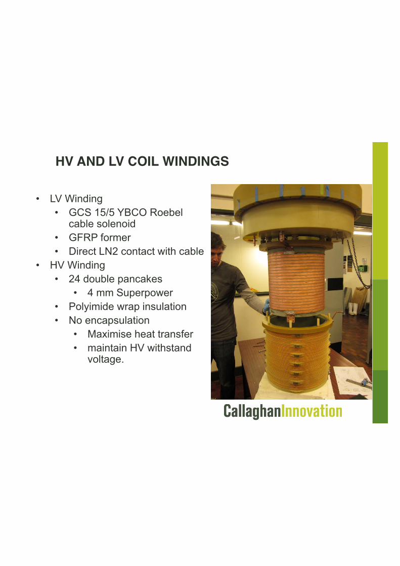
HV AND LV COIL WINDINGS
• LV Winding• GCS 15/5 YBCO Roebel
cable solenoid• GFRP former• Direct LN2 contact with cable
• HV Winding• 24 double pancakes
• 4 mm Superpower• Polyimide wrap insulation• No encapsulation
• Maximise heat transfer• maintain HV withstand
voltage.

Single phase AC loss asair core transformer
• Loss is hysteretic• 50 Hz loss per phase at rated
current is < 200 W• Loss ~ I3.5
• Loss at half power only 18 W• Roebel cable removes the AC
loss obstacle to HTS transformer commercialisation
0.00001
0.0001
0.001
0.01
0.1
1
100 200 500 1000 2000
Phase A 56.62 Hz
Phase B 56.88 Hz
Phase C 56.73 Hz
Isecondary (A peak)
Q (J
.m-1
.cyc
le-1
)

THERMAL BUDGET (AT RATED LOAD)
1 from experiment2 McFee, 1959, found to be consistent with experiment
Our sizing of the cooling system has allowed for 1100W heat load at rated operation.
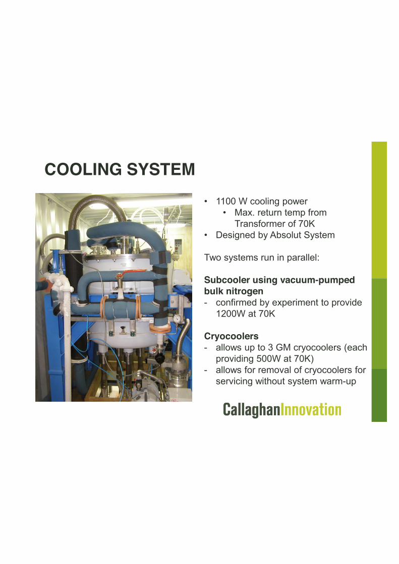
COOLING SYSTEM• 1100 W cooling power
• Max. return temp from Transformer of 70K
• Designed by Absolut System
Two systems run in parallel:
Subcooler using vacuum-pumped bulk nitrogen- confirmed by experiment to provide
1200W at 70K
Cryocoolers- allows up to 3 GM cryocoolers (each
providing 500W at 70K)- allows for removal of cryocoolers for
servicing without system warm-up

TRANSFORMER COMMISSIONING
Approx. Mass (kg)Core 2000
Windings + Cryostats 600
Liquid Nitrogen 200
TOTAL 2800

COMMISSIONING TESTINGTesting according to IEC 60076 underway now, includes:
- Short circuit impedance and load loss
- No load loss, current and harmonics
- Temperature rise test at rated current to ensure effectiveness of cooling system
- AC withstand voltage test
- Separate source AC withstand voltage test (28kV withstand on HV, 3kV withstand on LV for one minute)
- Induced AC withstand voltage test (tests turn-to-turn insulation)

COMMISSIONING TESTINGCurrently in progress, but completed so far;
• Phase turn ratios confirmed; A 11.02V : a 238.4 mV, B 10.58V : b 228.8 mV, C 11.14V : c 241.2 mV
• Primary winding insulation resistance; greater than 1 G-Ohm
• Vector group confirmed; DYN11
• Load testing and cooling system check.
• Loading held for 1 hour (stabilisation) to verify cooling system ability.
• 100 kVA, 250 kVA, 500 kVA and 650 kVA equivalent current loading applied

Conclusions• A 1 MVA 3-phase transformer using 2G Roebel
cable has been designed and constructed• Commissioning and optimisation prior to site
installation in the Vector network• At full rated current the thermal load from AC loss is
comparable to the heat load from the bushings• Measured AC loss is at low end of expectations
• Lower loss driven by use of transposed Roebel cable
• LV loss lower than Norris prediction and in line with Enric Pardo modelling

“AC LOSS NOT A FUNDAMENTAL OBSTACLE TO HTS TRANSFORMER COMMERCIALISATION”
• At ratings > 1 MVA, with secondary voltage increased to distribution levels e.g. 33 – 11 kV, currents remain ~ 1-2 kA
� Current lead loss – unchanged
� Cryostat loss – slight increase with size
� AC loss increase ~ proportional to wire length
• Non-linear scaling of losses with ratings – even more advantages of low loss Roebel cable
• AC loss ~ I4 at I/Ic ~ 0.8 → large reductions possible by reducing I/Ic : lower T → 65 K, more strands, better wire
• When using Roebel cable, AC loss not a fundamental obstacle to HTS transformer commercialisation

PROJECT PARTNERS
www.hts110.co.nz
www.wtc.com.au
www.eteltransformers.co.nz
www.fabrum.co.nz
www.pbworld.com
www.vectorelectricity.co.nz
www.gcsuperconductors.com
www.weltec.ac.nz
www.aut.ac.nz
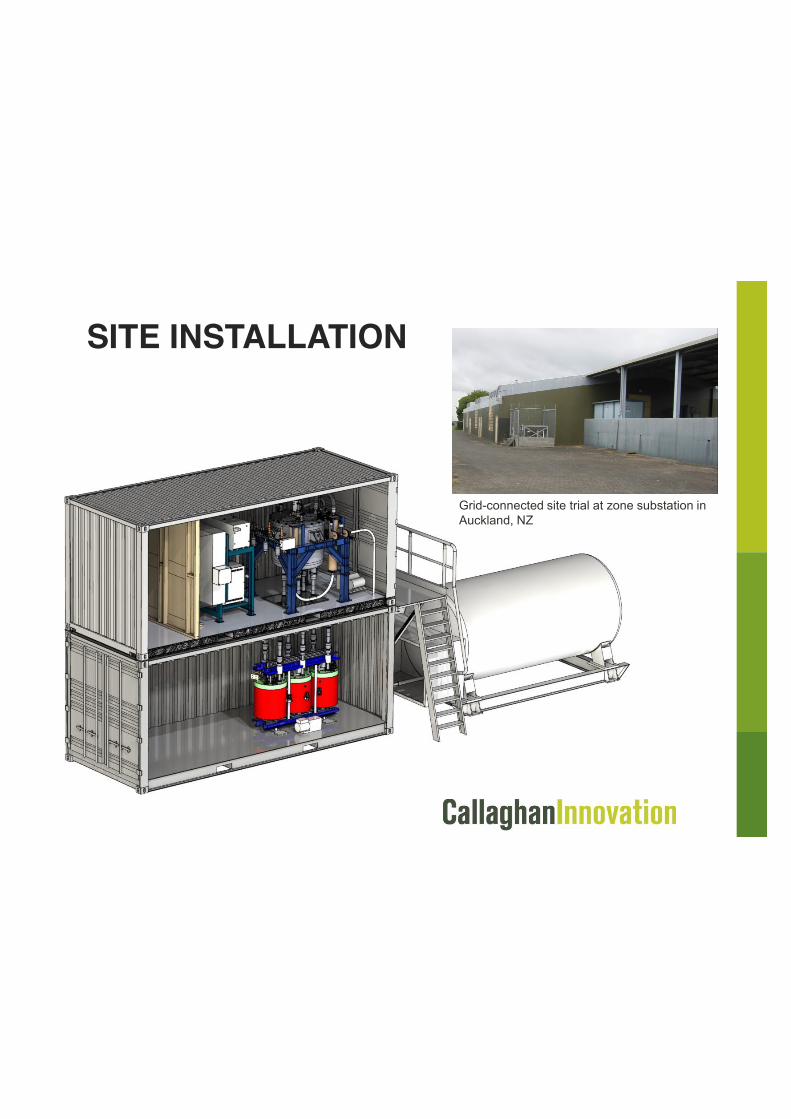
SITE INSTALLATION
Grid-connected site trial at zone substation in Auckland, NZ