Embed Size (px)
Citation preview

Operation & Parts Manual LISTED
Commercial Upright Vacuum
MODELS: SMP14 10120180 SMP18 10120190
86306360-D 11/28/11

2
TABLE OF CONTENTS
Page No. Important Safety Instructions………………………. 2 Assembly……………………………………..………..4 General Information…………………………………..5 Specifications………………………………………….5 Recommended Spare Parts……………………….…5 Operating Instructions………………………………..6 Periodic Maintenance………………………………...7 Troubleshooting……………………………………….8 Repair Or Replace…………………………………….8 Wiring Diagram……………………………………….10 Parts Diagram/Parts List………………………11 - 16 Warranty………………………………………………17

3
IMPORTANT SAFETY INSTRUCTIONS Accidents due to misuse can only be prevented by those using the machine. To guard against injury, basic
safety precautions should be observed, including the following:
Read and follow all safety instructions.
This vacuum cleaner is designed to be safe when used to perform cleaning functions. Should damage occur to electrical or mechanical parts, cleaner should be repaired by ServiceMaster or competent service station before using in order to avoid further damage to machine or physical injury to user.
To reduce the risk of fire, electric shock, or injury:
Use only as described in this manual. Use only manufacturer’s recommended attachments. Do not use with damaged cord or plug. If the machine is not working properly, has been dropped, damaged, left outdoors, or dropped into water, return it to an authorized service center. Do not put any object into openings. Do not use the machine with any openings blocked. Keep openings free of dust, lint, hair and anything that may reduce airflow. Do not use to pick up flammable or combustible liquids, such as gasoline, or use in areas where they may be present. Do not use outdoors or on wet surfaces. Do not unplug machine by pulling on cord. To unplug, grasp the plug, not the cord. Pulling it out by the cord itself can damage cord insulation and internal connections to plug. Do not pull or carry by cord, use cord as a handle, close a door on cord, or pull cord around sharp edges or corners. Do not pull/run cleaner over cord. Keep cord away from heated surfaces. Connect to a properly grounded outlet. See Grounding Instructions. Do not operate without dust bag and filter in place. Turn off all controls before unplugging. Wind cord no tighter than is necessary to retain it on the cord hooks. Your vacuum cleaner creates suction and contains a revolving brush. To avoid bodily injury from suction or moving parts, vacuum cleaner brush should not be placed against, or in close proximity of loose clothing, jewelry, hair or body surfaces while cleaner is connected to electrical outlet. Cleaner should not be used to vacuum clothing while it is being worn. Always plug your cleaner into a standard wall outlet. Use of extension cord or light socket with inadequate current-carrying capacity could result in electric shock or fire hazard. Disconnect cleaner from electrical outlet before servicing, such as changing bags or belts. You could receive bodily injury from moving parts of machine should switch accidentally be turned on. Disconnect cleaner from electrical outlet before detaching powerhead. Do not use your vacuum cleaner in areas where flammable and/or explosive vapor or dust is present to avoid possibility of fire or explosion. Some cleaning fluids can produce such vapors. Areas on which cleaning fluids have been used should be completely dry and thoroughly aired before being vacuumed.
SAVE THESE INSTRUCTIONS

4
SAFETY INSTRUCTIONS CONT'D. To avoid fire hazard, do not pick up matches, fireplace ashes, or smoking material with cleaner. Keep your work area well lighted to avoid picking up harmful materials (such as liquids, sharp objects, or burning substances) and avoid tripping accidents. Use care when operating the cleaner on irregular surfaces such as stairs. A falling cleaner could cause bodily injury and/or mechanical damage. A handle is provided near the bottom of the dust bag door to assist operating the cleaner on stairs. The handle is not intended to support the complete cleaner weight and should not be used to carry the cleaner. Proper storage of machines in an out-of-way area immediately after use will also prevent accidents caused by tripping over cleaner. Store your vacuum cleaners indoors in a cool, dry area not exposed to the weather to avoid electrical shock and/or cleaner damage. Exercise strict supervision to prevent bodily injury when using vacuum cleaner near children or when child is allowed to operate vacuum cleaner. Do not allow children to play with vacuum cleaner and never leave cleaner plugged in and unattended.
SAVE THESE INSTRUCTIONS

5
REF DESCRIPTION
1 HANDLE GRIP 2 HANDLE ASSEMBLY 3 BAG FULL INDICATOR 4 ON/OFF SWITCH 5 COVER RELEASE LATCH 6 EXHAUST FILTER COVER 7 FRONT COVER 8 MOTOR COVER 9 POWER HEAD 10 LOCKING CATCH 11 FOOT PEDAL 12 HOSE 13 RETAINING RING 14 CABLE 15 ATTACHMENT TUBE HANDLE 16 HANDLE CATCH 17 CARRYING HANDLE 18 CABLE HOOK 19 ATTACHMENT TUBE 20 DUST BAG HOUSING 21 CREVICE NOZZLE 22 UPHOLSTERY NOZZLE 23 PILE ADJUSTMENT KNOB 24 ATTACHMENT HANDLE PROJECTION 25 CONNECTING TUBE 26 SWIVEL NECK 27 SUPPORT LEVER
Assembling the vacuum cleaner Put the power head (9) on the floor with the swivel neck (26) and support lever (27) upright. Turn the locking catch (10) on the filter bag housing (20) to the left and place it carefully on the swivel neck and the support lever. Then turn the locking catch back. To lock the handle turn the handle catch (16) at the handle joint of the filter bag housing (20) forward, then slide the handle assembly (2) in as far as possible and lock it with the handle catch. Insert the attachment tube (19) into its storage position on the side of the machine. The attachment tube handle (15) must be placed on the projection (24). Slide the proper end of the hose into the tube (19). To connect the hose with the filter bag housing, insert the black hose end into the connecting tube (25) and slide it in completely. To unlock the hose press the retaining ring (13) at the projecting sections.
12
13
14
15 1617 18 19 20 21 22
23
11
10
9
8
76
5 43
21
12 2
25
13
27
9
26
20
2419
15

GENERAL INFORMATION
6
Grounding Instructions This machine must be grounded. If it should malfunction or breakdown, grounding provides a path of least resistance for electric current to reduce the risk of electric shock. This machine is equipped with a cord having an equipment-grounding conductor and grounding plug. The plug must be plugged into an appropriate outlet that is properly installed and grounded in accordance with all local codes and ordinances. Improper connection of the equipment-grounding conductor can result in a risk of electric shock. Check with a qualified electrician or service person if you are in doubt as to whether the outlet is properly grounded. Do not modify the plug provided with the appliance - if it will not fit the outlet, have a proper outlet installed by a qualified electrician. This appliance is for use on a nominal 120-volt circuit, and has a grounded plug that looks like the plug in “Fig. A”. A temporary adaptor that looks like the adaptor in “Fig. C” may be used to connect this plug to a 2-pole receptacle as shown in “Fig. B”, if a properly grounded outlet is not available. The temporary adaptor should be used only until a properly grounded outlet, (Fig. A) can be installed by a qualified electrician. The green colored rigid ear, lug, or wire extending from the adaptor must be connected to a permanent ground such as a properly grounded outlet box cover. Whenever the adaptor is used, it must be held in place by a metal screw.
The motors in the vacuum are permanently lubricated and sealed. Do not oil. Never operate the unit without a filter bag.
When disconnecting the power cord from the electrical outlet, grasp the plug. Pulling it out by the cord itself can damage the insulation and internal connections to the plug. SPECIFICATIONS
ITEM DIM/CAPACITY
Vacuum Motor Lamb, two-stage, non-bypass
Vacuum Motor Performance
Sealed waterlift 80" CFM (open) 105"
Brush Motor 150 watt Brush Replaceable strip, 12.7" Height 48.7" Overall Width 14" Weight 18 lbs.
Cable 40', 18 gauge, black with molded 3-prong plug
Electrical Operates on 120V, 60 cycle 3-wire grounded
Housing Injection molded, high impact ABS with protective coating
Bag Capacity 5.6 quarts Brush Drive Toothed neoprene timing belt RECOMMENDED SPARE PARTS
PART NO.
PRV NO.
DESCRIPTION QTY
86142650 5040HG HOSE 1 86142050 1037EH HANDLE GRIP CPL 1 86002400 2046 BRUSH STRIP 14” 2 86001640 4028 BRUSH STRIP 18” 2 86139120 1260DG CABLE, 3-WIRE 2
1947 POWER CABLE W/PLUG 2
86284840 5300 SM FILTER BAG PACK 2 PKG.
86142690 1875 HOSPITAL GRADE FILTER 2
86141370 1878 EXHAUST FILTER 2 86144620 5424DG RETAINING RING 2
! WARNING:

OPERATING INSTRUCTIONS
7
Preparation 1. Before putting the unit in service, check the filter
bag. If the bag is full or ripped, do not attempt to use the unit until a replacement filter bag is installed.
2. Inspect the condition of the power cord. If there is damage to the cord, report it to your supervisor immediately.
3. Plug in the unit and turn on the power switch. 4. With the tip of your toe, release the handle lock by
pressing down on the foot pedal. 5. Check the proper brush height.
• A "green light" indicates that the brush setting is correct and running properly.
• A "green and red light" indicates that the brush is not contacting the carpet sufficiently. Adjust the brush setting by turning the pile adjustment button to a lower number. If the light still shows at position #1, the brush strip is worn and must be replaced.
• A "red light" indicates that the brush has become blocked and is not turning. Turn the unit off, unplug the cord from the outlet and clear the blockage.
Operation 1. The powerhead motor stops automatically
when the dust bag housing is brought to an upright position. If the powerhead is not operating, make sure that the dust bag housing is not in the upright position.
2. If the bag full indicator light comes on during
operation, check the following: • Is the filter bag full? • Is there a blockage in the hose or
powerhead?
To replace the filter bag: A. Pull the cover release latch and lift from
the dust bag housing. B. Slide the dust bag sealing plate from the
holder. C. Slide the sealing plate of a new bag into
the holder and push it in firmly. D. Slip the bottom of the filter bag into the
fold of the hospital filter.
BE CAREFUL NOT TO RIP THE FILTER BAG
DURING INSTALLATION.

8
3. To disconnect the powerhead, turn the locking catch clockwise and lift the upper unit off the powerhead.
Clean Up 1. Disconnect the plug from the wall outlet by
grasping the wall plug and pulling straight out of the outlet.
2. Inspect the filter bag. If full, replace immediately. 3. Loosely wrap the cord around the cord hooks. 4. Wipe down the unit. PERIODIC MAINTENANCE Always remember to unplug the machine before doing any maintenance or repair. Daily: Powerhead 1. Clear any debris or obstructions (string, thread,
etc.) from the roller assembly. 2. Check for obstructions in the neck and throat of
the powerhead. 3. Check the operation of the foot pedal. 4. Check the micro-switch in the chassis that controls
the powerhead for smooth operation. Turn on machine and move dust bag housing from the storage position to the working position (brush motor will start and stop).
Chassis 5. Make sure all the filters are free of visible dirt. 6. Check that the filter cover is properly sealed. 7. Identify and report a damaged cord or plug
immediately. 8. Check the strain reliefs in the body and below the
handle to make sure they are securely attached. 9. Seal the hand nozzle and see if the bag full
indicator light comes on. 10. Check for cracks or pin hole leaks in the hose.
Remove any obstructions.
! WARNING:
9
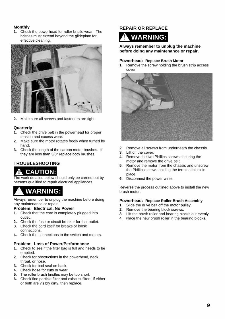
Monthly 1. Check the powerhead for roller bristle wear. The
bristles must extend beyond the glideplate for effective cleaning.
2. Make sure all screws and fasteners are tight. Quarterly 1. Check the drive belt in the powerhead for proper
tension and excess wear. 2. Make sure the motor rotates freely when turned by
hand. 3. Check the length of the carbon motor brushes. If
they are less than 3/8" replace both brushes. TROUBLESHOOTING The work detailed below should only be carried out by persons qualified to repair electrical appliances. Always remember to unplug the machine before doing any maintenance or repair. Problem: Electrical, No Power 1. Check that the cord is completely plugged into
outlet. 2. Check the fuse or circuit breaker for that outlet. 3. Check the cord itself for breaks or loose
connections. 4. Check the connections to the switch and motors. Problem: Loss of Power/Performance 1. Check to see if the filter bag is full and needs to be
emptied. 2. Check for obstructions in the powerhead, neck
throat, or hose. 3. Check for bad seal on back. 4. Check hose for cuts or wear. 5. The roller brush bristles may be too short. 6. Check fine particle filter and exhaust filter. If either
or both are visibly dirty, then replace.
REPAIR OR REPLACE Always remember to unplug the machine before doing any maintenance or repair. Powerhead: Replace Brush Motor 1. Remove the screw holding the brush strip access
cover. 2. Remove all screws from underneath the chassis. 3. Lift off the cover. 4. Remove the two Phillips screws securing the
motor and remove the drive belt. 5. Remove the motor from the chassis and unscrew
the Phillips screws holding the terminal block in place.
6. Disconnect the power wires. Reverse the process outlined above to install the new brush motor. Powerhead: Replace Roller Brush Assembly 1. Slide the drive belt off the motor pulley. 2. Remove the bearing block screws. 3. Lift the brush roller and bearing blocks out evenly. 4. Place the new brush roller in the bearing blocks.
! CAUTION:
! WARNING:
! WARNING:

10
Powerhead: Replace Motor Pulley 1. Insert the tip of a straight-blade screwdriver into a
groove of the motor pulley. 2. Give the screwdriver a light tap with a hammer in a
counter clockwise direction. 3. Unscrew the motor pulley by hand and remove. Reverse the process outlined above to install the new motor pulley. Powerhead: Replace Wheel Assembly 1. Unscrew the three screws and take off the axle
clamps holding the assembly in place. 2. When replacing the new assembly, apply a small
amount of lubricant to the axle. 3. Hook one end of the axle spring to the axle. 4. Pull the other end of the spring approximately a
quarter of a turn around the axle and put the axle in place.
5. Replace the axle clamps and screws. Powerhead: Replace Brush Strips 1. Remove the screw holding the brush strip cover in
place. 2. Using pliers, pull out the brush strips. 3. Install the new brush strips with the pointed end of
the strip entering first. To Replace Power Cord: 1. Remove the handle's strain relief attachment
screw. 2. Open the small cover near the handle 3. Disconnect the green, black, and white wires for
the terminals. 4. The strain relief must be removed before the cord
can be removed. Reverse the process outlined above to install the new power cord.
Power Cord Replacement
To Replace Power Switch and Circuit Board: 1. Remove the wand from it's housing. 2. Remove the screws and the wand's housing cover. 3. Remove the electrical leads from the board's
terminals. 4. Replace the switch and board assembly. To Replace the Vacuum Motor: 1. Remove the bumper just beneath the motor cover. 2. Remove the four screws on the motor cover. 3. Disconnect the wires, noting where each wire is
removed from.

11
To Replace the Handle: 1. Remove the screw holding the handle and the
strain relief. 2. Remove handle. Wiring Diagram
REF PART NO.
PRV NO. DESCRIPTION
A1 86146310 1491JE UPHOLSTERY NOZZLE
A2 86140860 1092JE CREVICE NOZZLE
B1 86141520 1495US EXTENSION HOSE
B2 86141510 1084 EXTENSION TUBE
B3 86141000 1094HG DUSTING BRUSH
B4 86146270 1090HG UPHOLSTERY NOZZLE, GRY
B5 86146530 1325HG WALL/UPHOL BRUSH, GRY
C1 86284840 5300SM SENSOR FILTER BAG PACK
C2 86141370 1878 EXHAUST FILTER 370/470
C3 86143430 1825 MOTOR FILTER
C4 86142690 1875 HOSPITAL GRADE FILTER
Service Parts
Attachments Optional Attachments
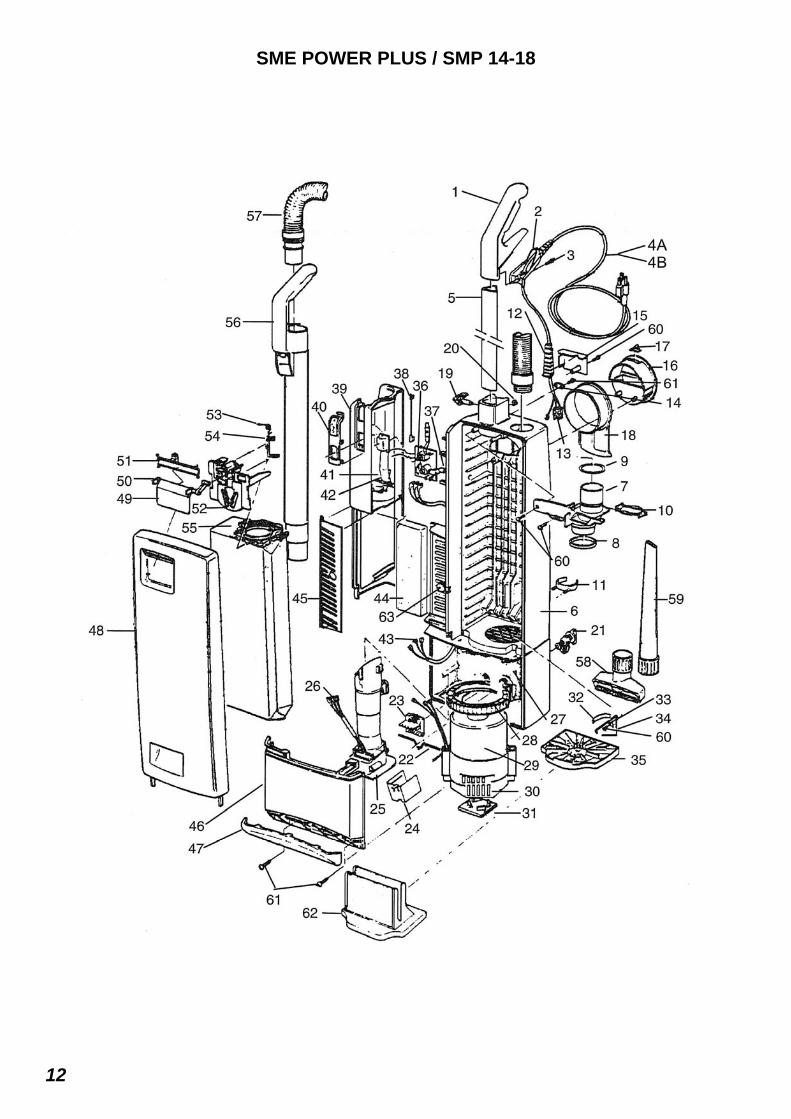
SME POWER PLUS / SMP 14-18
12

PARTS LIST / SME POWER PLUS / SMP 14-18
13
REF PART NO. PRV NO. DESCRIPTION
1 86142050 1037EH HANDLE GRIP COMPLETE 2 86142120 1596HG HANDLE COVER 3 86147120 0127 SCREW, M4 X 10 MM TAPTITE
4A 86139120 1260dg CABLE, 3-WIRE DK GRY 4B 86335360 1947 CORD SET, GRAY 17AWG 5 86142150 1848 HANDLE 6 86141070 1832HG DUST BAG HOUSING 7 86142840 1835HG INTERNAL COVER 370/470 8 86144930 5289 SEAL, FILTER TUBE 9 86144900 5043 SEAL
10 86144620 5424DG RETAINING RING, DK GRY 11 86140080 1823HG CLIP, DUST BAG HOUSING-SR12 12 86141970 5359HG GROMMET 13 86146170 0502 TERM. BLOCK 14 86139110 1030UL CABLE CLAMP 15 86140430 1812HG COVER 16 86139430 1814HG CARRYING HANDLE 17 86145350 5146 STOP SPRING (HOOK) 18 86139170 1813HG CABLE HOOK 19 86352680 1859dg HANDLE CATCH 20 86140040 0161 CLIP, 4 DIN 6799 21 86143080 0850DG LOCKING CATCH 22 86143100 1811 LOCKING ROD 23 86146200 1265UL TERM. BLOCK 24 86140420 1524 COVER, TERMINAL BLOCK 25 86140220 1807HG CONNECTOR 26 86141590 1837 FEMALE CONTACT HOLDER 27 86145170 1851 SOUND INSULATION 28 86146380 1047 VAC MOTOR SEAL 29 86146410 1843 VAC MOTOR 86139400 05117S CARBON BRUSH SET 100/120V
30 86143410 1821UL MOTOR COVER 31 86143420 1822 MOTOR SUPPORT 32 86143010 1027 LEAF SPRING 33 86139970 1073 CLAMP 34 86140230 1824 CONNECTING ROD 35 86143430 1825 MOTOR FILTER (OPT.) 36 86139950 1936ER CIRCUIT BOARD 120V 3-P UL 86143760 1903 PC BOARD COVER
37 86141680 1860 FITTING 38 86141990 0851UL GROUNDING WIRE 39 86146470 1852WI VACUUM TUBE COVER 40 86143040 1869HG LENS BAG LIGHT INDICATOR 41 86145580 1830BL SWITCH BUTTON 42 86145220 1862 SPRING 43 86142830 1834 INTERNAL CABLE 44 86141370 1878 EXHAUST FILTER 370/470 45 86141360 1802HG EXHAUST FILTER COVER 46 86143460 1853NE MOTOR COVER 47 86141050 1804HG DUST BAG HSG. BUMP. 48 86141750 1846WI FRONT COVER CPL. 49 86140440 1818BL COVER RELEASE 50 86144970 6040 SEAL, RELEASE COVER 51 86143940 1819 PLASTIC AXLE COVER 52 86138040 1847 BAG HOLDER, CPL. 53 86144760 5091 SAFE. CATCH SPRING 54 86144750 1817 SAFETY CATCH 55 86284840 5300SM SENSOR FILTER BAG PACK 56 86141550 5045HG EXTENSION TUBE, GRY 57 86142650 5040sb HOSE, SENSOR GRY 58 86146310 1491JE UPHOLSTERY NOZZLE 59 86140860 1092JE CREVICE NOZZLE 60 86147030 0102 SCREW M3,9 X13 MM DIN 7981 61 86147040 0103ER SCR, M3,9 X16 MM DIN 7981 62 86142690 1875 HOSPITAL GRADE FILTER 63 86144610 1884HG RETAINING BUTTON

SME POWER PLUS / SMP14
14

PARTS LIST / SME POWER PLUS / SMP14
15
REF PART NO. PRV NO. DESCRIPTION 1 86140530 2542 COVER, VSE BRUSH STRIP 2 86140600 2643WI COVER 370, CPL 3 86147030 0102 SCREW, M3,9 X 13 MM DIN 7981 4 86146550 0141 WASHER, LOCK 5 86145880 2613 SWIVEL SUPPORT 6 86146560 0155 WASHER 7 86145780 2467 SWIVEL NECK PLASTIC BEARING 8 86145840 2602HG SWIVEL NECK COVER 370/470 9 86146760 2612UL WIRE, SWIVEL NECK ASSEMBLY
10 86145870 2610UL SWIVEL NECK ASSY 11 86145620 2605 SWITCH LEVER 12 86143290 2624 MICRO SWITCH SUPPORT CPL. 13 86143240 0531 MICRO SWITCH F. SWIVEL 14 86143680 0849UL NECK WIRE 15 86235390 2049 DRIVE BELT 16 86144420 2025 PULLEY- MOTOR 17 86138460 2241UL BRUSH DRIVE MOTOR 115V U70G32 - 86139380 05095S CARBON BRUSH SET 120V
18 86144880 0174 SCREW, BRIDGE SR 19 86147060 0105 SCREW, M3,9 C 19 MM DIN7981CPLT 20 86002440 2046 BRUSH STRIP 14” 21 86138100 2047 BEARING BLOCK VSM/VSE RH 22 86138430 2030ER BRUSH ASSY CPL. 23 86138110 2091 BEARING BLOCK VSM/VSE LH 24 86144430 2458 PULLEY, VSE BRUSH ROLLER 25 86140290 2572ER CONTROL PC BOARD VSE1/3 - 86143780 2636 PC BOARD COVER
26 86145450 2653hg SUPPORT LEVER 27 86345580 2651 SPRING, VSE RETURN 28 86147040 0103 SCREW, M3,9 X 16 MM DIN 7981 29 86145270 4019 SPRING 30 86138860 2522HG BUMPER 31 86143830 2622HG PILE ADJ. KNOB 14” 32 86139670 2543HG CHASSIS VSP14/JAV14 33 86143220 2005 METAL PLATE 34 86141700 2528OR FOOT PEDAL 35 86146620 2614HG WHEEL 36 86147070 0111 SCREW, M5 X 30 MM DIN 7985A NP 37 86137880 2524 AXLE, VSE1 PILE ADJUSTMENT 38 86140000 2014 AXLE CLAMP 39 86146610 2608HG WHEEL , PILE ADJ. 40 86146570 2010 WHEEL RETURN SPRING 41 86137890 2525 AXLE VSE-1

SME POWER PLUS / SMP18
16
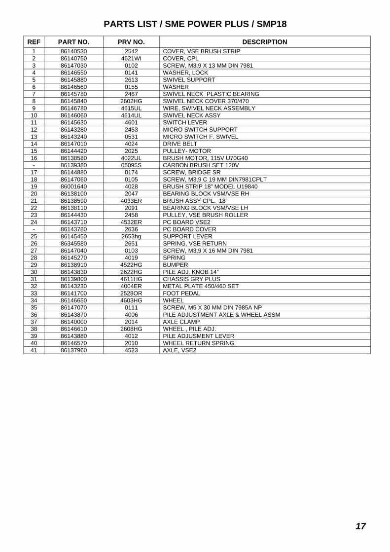
PARTS LIST / SME POWER PLUS / SMP18
17
REF PART NO. PRV NO. DESCRIPTION 1 86140530 2542 COVER, VSE BRUSH STRIP 2 86140750 4621WI COVER, CPL 3 86147030 0102 SCREW, M3,9 X 13 MM DIN 7981 4 86146550 0141 WASHER, LOCK 5 86145880 2613 SWIVEL SUPPORT 6 86146560 0155 WASHER 7 86145780 2467 SWIVEL NECK PLASTIC BEARING 8 86145840 2602HG SWIVEL NECK COVER 370/470 9 86146780 4615UL WIRE, SWIVEL NECK ASSEMBLY
10 86146060 4614UL SWIVEL NECK ASSY 11 86145630 4601 SWITCH LEVER 12 86143280 2453 MICRO SWITCH SUPPORT 13 86143240 0531 MICRO SWITCH F. SWIVEL 14 86147010 4024 DRIVE BELT 15 86144420 2025 PULLEY- MOTOR 16 86138580 4022UL BRUSH MOTOR, 115V U70G40 - 86139380 05095S CARBON BRUSH SET 120V
17 86144880 0174 SCREW, BRIDGE SR 18 86147060 0105 SCREW, M3,9 C 19 MM DIN7981CPLT 19 86001640 4028 BRUSH STRIP 18” MODEL U19840 20 86138100 2047 BEARING BLOCK VSM/VSE RH 21 86138590 4033ER BRUSH ASSY CPL. 18” 22 86138110 2091 BEARING BLOCK VSM/VSE LH 23 86144430 2458 PULLEY, VSE BRUSH ROLLER 24 86143710 4532ER PC BOARD VSE2 - 86143780 2636 PC BOARD COVER
25 86145450 2653hg SUPPORT LEVER 26 86345580 2651 SPRING, VSE RETURN 27 86147040 0103 SCREW, M3,9 X 16 MM DIN 7981 28 86145270 4019 SPRING 29 86138910 4522HG BUMPER 30 86143830 2622HG PILE ADJ. KNOB 14” 31 86139800 4611HG CHASSIS GRY PLUS 32 86143230 4004ER METAL PLATE 450/460 SET 33 86141700 2528OR FOOT PEDAL 34 86146650 4603HG WHEEL 35 86147070 0111 SCREW, M5 X 30 MM DIN 7985A NP 36 86143870 4006 PILE ADJUSTMENT AXLE & WHEEL ASSM 37 86140000 2014 AXLE CLAMP 38 86146610 2608HG WHEEL , PILE ADJ. 39 86143880 4012 PILE ADJUSMENT LEVER 40 86146570 2010 WHEEL RETURN SPRING 41 86137960 4523 AXLE, VSE2

NOTES:
18

LIMITED WARRANTY
The ServiceMaster Company warrants that this equipment, which has been manufactured, tested and inspected in accordance with carefully specified engineering specifications, is free from defects in material and workmanship. This warranty is, however, subject to the following qualifications, conditions and limitations which are set forth to provide you and all users of ServiceMaster equipment with information concerning the duration, extent, availability and applicability of the ServiceMaster Limited Warranty, the procedure to be taken to obtain its performance and other information concerning the ServiceMaster Warranty policy.
Duration of Warranty and to whom extended
This warranty extends for one year from the date of the original purchase of the ServiceMaster equipment by the end user. Parts of ServiceMaster equipment not covered
by warranty
Certain parts of the equipment require replacement in the ordinary course of use do to normal wear by reason of their characteristics. These are normal wear items such as cords, switches, carbon brushes, bearings, filters, brush strips, etc. Exceptions and exclusions from warranty
This equipment is required to be used on electric current as indicated on the nameplate. Otherwise damage, defects, malfunctions, or other failures of the equipment arising from use on electric current not as indicated are excepted and excluded from this warranty. Defects, malfunctions, failure or damage of the equipment caused by improper, unreasonable or negligent use or abuse while in the possession of the purchaser are likewise excluded from this warranty. If repair work is done on your equipment by anyone other than those designated as authorized to perform such work without first having obtained factory instructions, The ServiceMaster Company, at its sole option, may determine the this warranty will not apply and that
reimbursement for such repair will not be made because of the failure to comply with such specified instructions.
Procedures to be taken to obtain performance of warranty
Repairs - To secure repair of the equipment or any warranted parts under this warranty, the following procedure should be taken: The inoperative equipment or warranted parts, together with satisfactory evidence of the purchase date, must be delivered, with shipping and delivery charges prepaid, to a ServiceMaster authorized service center. If you are unable to locate the foregoing, you may write or otherwise communicate with the Warranty Department of the ServiceMaster Company for instruction before repair service is performed by anyone else (800-937-9444). The Warranty Department will provide the location of the closest available ServiceMaster authorized service center. Upon compliance with the above procedure, all warranted defects will be repaired, at no additional charge or cost to the customer, and the repaired product returned to the customer, with all shipping and delivery charges reimbursed upon request. In the procedures set forth above, PLEASE MAKE CERTAIN to state the ServiceMaster model, type and serial number as shown on the name plate of the equipment. REPLACEMENT - In the event of a defect, malfunction or failure of your equipment of any warranted part to conform to this warranty, The ServiceMaster Company may, as its sole option and expense, replace the equipment or any warranted part with another new identical or reasonably equivalent model or part in lieu of repairing the defect. This warranty gives you specific legal rights, and you may also have other rights which vary from state to state. There are no other warranties expressed or implied, including any implied warranties or merchantability or fitness for a particular purpose. In no event shall ServiceMaster be liable for speculative or consequential damages resulting from the failure thereof.
The ServiceMaster Company One ServiceMaster Way
Downers Grove, IL 60515 USA (800-937-9444)

06820 – 11.2011 86306360 D 11/28/2011