Embed Size (px)
Citation preview

Commercial ElectricWater Heaters
9kW – 900kW Input Models
CHP-I&S-01
INSTALLATION AND SERVICE MANUAL
1
If the information in thismanual is not followed exactly, a fire orexplosion may result causing propertydamage, personal injury or loss of life.Do not store or use gasoline or otherflammable vapors and liquids in the vicinity ofthis or any other appliance.
USE THIS APPLIANCE IF ANYPART HAS BEEN UNDER WATER. THEPOSSIBLE DAMAGE TO A FLOODEDAPPLIANCE CAN BE EXTENSIVE ANDPRESENT NUMEROUS SAFETY HAZARDS.ANY APPLIANCE THAT HAS BEEN UNDERWATER MUST BE REPLACED.
Installation and service must be performed byQualified Service Personnel Only.
Factory warranty (shipped with unit) does notapply to units improperly installed or improperlyoperated.
Experience has shown that improper installationor system design, rather than faulty equipment, isthe cause of most operating problems.
Excessive water hardness causing a lime/scalebuild-up in the heater and/or on the immersionheating elements is not the fault of the equipmentand is not covered under the manufacturer’swarranty. (See Water Treatment and WaterChemistry)
Do not energize electrical system before heateris completely filled with water. Damage causedto the immersion heating elements by dry fire isnot covered under the manufacturer’s warranty.Follow start up procedure in the manual. Water heater corrosion and component failurecaused by air-borne chemical vapors is notcovered under the manufacturer’s warranty.Corrosion damage caused by current leakage dueto improper grounding of electrical systems orelectronic components to the storage tank andrelated piping is not covered by themanufacturer’s warranty. Under no circumstancewill the manufacturer be liable for consequentialdamages resulting from the installation or use ofthis equipment. Correct installation procedureand local codes must be adhered to.
This manual supplies information for theinstallation, operation and servicing of theappliance. It is strongly recommended that thismanual be reviewed completely beforeproceeding with an installation. Upon receivingequipment, check for signs of shipping damage.Pay particular attention to parts accompanyingthe water heater, which may show signs of beinghit or otherwise being mishandled. Verify totalnumber of pieces shown on packing slip withthose actually received. In case there is damageor a shortage, immediately notify carrier.
CHECKING EQUIPMENT
WARNING:
NOTE: Retain this manual for future reference.
WARNING:Improper Installation, Adjustment,Alteration, Service or Maintenance
can cause injury or property damage. Refer to this manual. For assistance or additional
information consult a qualified installer, service agency or the electric utility.
SPECIAL INSTRUCTIONS TO OWNER
WARRANTY
DO NOT
2
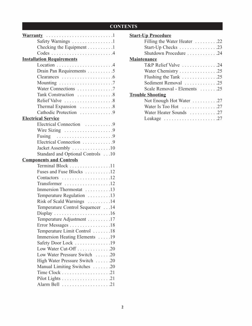
CONTENTS
Start-Up ProcedureFilling the Water Heater . . . . . . . . .22Start-Up Checks . . . . . . . . . . . . . . .23Shutdown Procedure . . . . . . . . . . . .24
MaintenanceT&P Relief Valve . . . . . . . . . . . . . .24Water Chemistry . . . . . . . . . . . . . . .25Flushing the Tank . . . . . . . . . . . . . .25Sediment Removal . . . . . . . . . . . . .25Scale Removal - Elements . . . . . . .25
Trouble ShootingNot Enough Hot Water . . . . . . . . . .27Water Is Too Hot . . . . . . . . . . . . . .27Water Heater Sounds . . . . . . . . . . .27Leakage . . . . . . . . . . . . . . . . . . . . .27
Warranty . . . . . . . . . . . . . . . . . . . . . . . . . .1Safety Warnings . . . . . . . . . . . . . . . .1Checking the Equipment . . . . . . . . . .1Codes . . . . . . . . . . . . . . . . . . . . . . . .4
Installation RequirementsLocation . . . . . . . . . . . . . . . . . . . . . .4Drain Pan Requirements . . . . . . . . . .5Clearances . . . . . . . . . . . . . . . . . . . .6Mounting . . . . . . . . . . . . . . . . . . . . .7Water Connections . . . . . . . . . . . . . .7Tank Construction . . . . . . . . . . . . . .8Relief Valve . . . . . . . . . . . . . . . . . . .8Thermal Expansion . . . . . . . . . . . . .8Cathodic Protection . . . . . . . . . . . . .9
Electrical ServiceElectrical Connection . . . . . . . . . . .9Wire Sizing . . . . . . . . . . . . . . . . . . .9Fusing . . . . . . . . . . . . . . . . . . . . . .9Electrical Connection . . . . . . . . . . . .9Jacket Assembly . . . . . . . . . . . . . . .10Standard and Optional Controls . . .10
Components and ControlsTerminal Block . . . . . . . . . . . . . . . .11Fuses and Fuse Blocks . . . . . . . . . .12Contactors . . . . . . . . . . . . . . . . . . .12Transformer . . . . . . . . . . . . . . . . . .12Immersion Thermostat . . . . . . . . . .13Temperature Regulation . . . . . . . . .13Risk of Scald Warnings . . . . . . . . .14Temperature Control Sequencer . . .14Display . . . . . . . . . . . . . . . . . . . . . .16Temperature Adjustment . . . . . . . . .17Error Messages . . . . . . . . . . . . . . . .18Temperature Limit Control . . . . . . .18Immersion Heating Elements . . . . .19Safety Door Lock . . . . . . . . . . . . . .19Low Water Cut-Off . . . . . . . . . . . . .20Low Water Pressure Switch . . . . . .20High Water Pressure Switch . . . . . .20Manual Limiting Switches . . . . . . .20Time Clock . . . . . . . . . . . . . . . . . . .21Pilot Lights . . . . . . . . . . . . . . . . . . .21Alarm Bell . . . . . . . . . . . . . . . . . . .21

3
FIG. 2 Front View Vertical Square ModelsFIG. 1 Front View Vertical Round Models
FIG. 3 Front View Horizontal Models
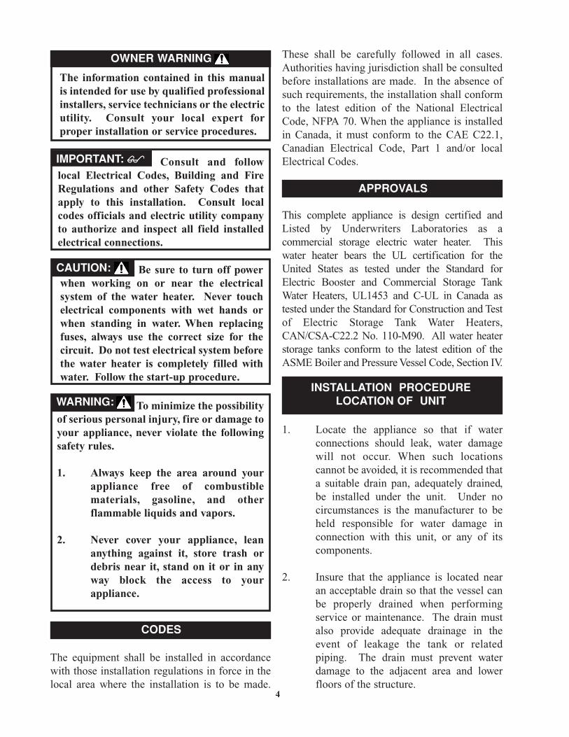
To minimize the possibilityof serious personal injury, fire or damage toyour appliance, never violate the followingsafety rules.
1. Always keep the area around yourappliance free of combustiblematerials, gasoline, and otherflammable liquids and vapors.
2. Never cover your appliance, leananything against it, store trash ordebris near it, stand on it or in anyway block the access to yourappliance.
Be sure to turn off powerwhen working on or near the electricalsystem of the water heater. Never touchelectrical components with wet hands orwhen standing in water. When replacingfuses, always use the correct size for thecircuit. Do not test electrical system beforethe water heater is completely filled withwater. Follow the start-up procedure.
Consult and followlocal Electrical Codes, Building and FireRegulations and other Safety Codes thatapply to this installation. Consult localcodes officials and electric utility companyto authorize and inspect all field installedelectrical connections.
The equipment shall be installed in accordancewith those installation regulations in force in thelocal area where the installation is to be made.
These shall be carefully followed in all cases.Authorities having jurisdiction shall be consultedbefore installations are made. In the absence ofsuch requirements, the installation shall conformto the latest edition of the National ElectricalCode, NFPA 70. When the appliance is installedin Canada, it must conform to the CAE C22.1,Canadian Electrical Code, Part 1 and/or localElectrical Codes.
This complete appliance is design certified andListed by Underwriters Laboratories as acommercial storage electric water heater. Thiswater heater bears the UL certification for theUnited States as tested under the Standard forElectric Booster and Commercial Storage TankWater Heaters, UL1453 and C-UL in Canada astested under the Standard for Construction and Testof Electric Storage Tank Water Heaters,CAN/CSA-C22.2 No. 110-M90. All water heaterstorage tanks conform to the latest edition of theASME Boiler and Pressure Vessel Code, Section IV.
1. Locate the appliance so that if waterconnections should leak, water damagewill not occur. When such locationscannot be avoided, it is recommended thata suitable drain pan, adequately drained,be installed under the unit. Under nocircumstances is the manufacturer to beheld responsible for water damage inconnection with this unit, or any of itscomponents.
2. Insure that the appliance is located nearan acceptable drain so that the vessel canbe properly drained when performingservice or maintenance. The drain mustalso provide adequate drainage in theevent of leakage the tank or relatedpiping. The drain must prevent waterdamage to the adjacent area and lowerfloors of the structure.
4
INSTALLATION PROCEDURELOCATION OF UNIT
OWNER WARNING
IMPORTANT:��
CAUTION:
WARNING:
CODES
APPROVALS
The information contained in this manualis intended for use by qualified professionalinstallers, service technicians or the electricutility. Consult your local expert forproper installation or service procedures.
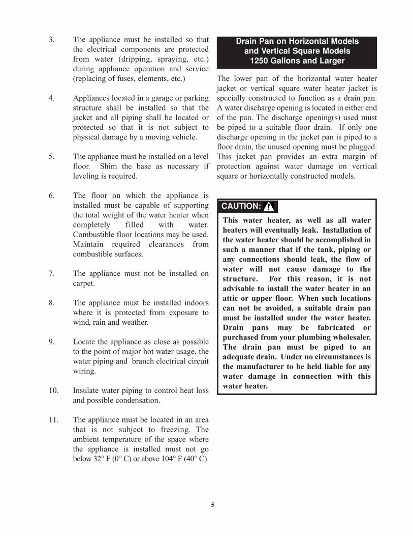
3. The appliance must be installed so thatthe electrical components are protectedfrom water (dripping, spraying, etc.)during appliance operation and service(replacing of fuses, elements, etc.)
4. Appliances located in a garage or parkingstructure shall be installed so that thejacket and all piping shall be located orprotected so that it is not subject tophysical damage by a moving vehicle.
5. The appliance must be installed on a levelfloor. Shim the base as necessary ifleveling is required.
6. The floor on which the appliance isinstalled must be capable of supportingthe total weight of the water heater whencompletely filled with water.Combustible floor locations may be used.Maintain required clearances fromcombustible surfaces.
7. The appliance must not be installed oncarpet.
8. The appliance must be installed indoorswhere it is protected from exposure towind, rain and weather.
9. Locate the appliance as close as possibleto the point of major hot water usage, thewater piping and branch electrical circuitwiring.
10. Insulate water piping to control heat lossand possible condensation.
11. The appliance must be located in an areathat is not subject to freezing. Theambient temperature of the space wherethe appliance is installed must not gobelow 32° F (0° C) or above 104° F (40° C).
The lower pan of the horizontal water heaterjacket or vertical square water heater jacket isspecially constructed to function as a drain pan.A water discharge opening is located in either endof the pan. The discharge opening(s) used mustbe piped to a suitable floor drain. If only onedischarge opening in the jacket pan is piped to afloor drain, the unused opening must be plugged.This jacket pan provides an extra margin ofprotection against water damage on verticalsquare or horizontally constructed models.
5
Drain Pan on Horizontal Modelsand Vertical Square Models
1250 Gallons and Larger
CAUTION:
This water heater, as well as all waterheaters will eventually leak. Installation ofthe water heater should be accomplished insuch a manner that if the tank, piping orany connections should leak, the flow ofwater will not cause damage to thestructure. For this reason, it is notadvisable to install the water heater in anattic or upper floor. When such locationscan not be avoided, a suitable drain panmust be installed under the water heater.Drain pans may be fabricated orpurchased from your plumbing wholesaler.The drain pan must be piped to anadequate drain. Under no circumstances isthe manufacturer to be held liable for anywater damage in connection with thiswater heater.
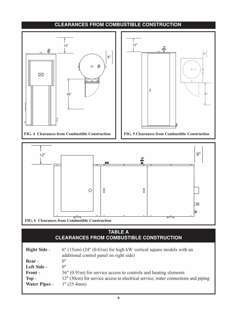
Right Side - 6" (15cm) (24" (0.61m) for high kW vertical square models with an additional control panel on right side)
Rear - 0" Left Side - 0" Front - 36" (0.91m) for service access to controls and heating elementsTop - 12" (30cm) for service access to electrical service, water connections and pipingWater Pipes - 1" (25.4mm)
6
FIG. 5 Clearances from Combustible Construction
12"
36"
6"
FIG. 4 Clearances from Combustible Construction
CLEARANCES FROM COMBUSTIBLE CONSTRUCTION
6"12"
FIG. 6 Clearances from Combustible Construction
TABLE ACLEARANCES FROM COMBUSTIBLE CONSTRUCTION
12"
36"
6"

7
Maintain minimum specified clearances foradequate operation. All installations must allowsufficient space for servicing the electricalcomponents, water pipe connections, piping andother auxiliary equipment, as well as the appliance.
Multiple appliances may be installed in a modularwater heater installation. Multiple appliancesmay be installed side by side with minimumclearance between the sides of adjacentappliances because no service access is requiredfrom the sides on most models. Note that highkW input vertical square water heaters may havean additional control access panel located on theright side of the jacket requiring an additionalservice access from the right side.
The water heater should be mounted to the floorfollowing applicable architectural and local coderequirements or accepted standards for the specificsite and model purchased. In areas prone to seismicactivity, it is recommended that the water heater bemounted to the floor according to recommendedprocedures for the site. In some geographic areas,additional strapping or braces may be required,consult local codes for specific requirements.Proper mounting will help to make the water heaterless susceptible to seismic damage.
WATER CONNECTIONS
HANDHOLECLEANOUT
DRAIN
HOT WATEROUTLET
TEMPERATURE & PRESSURERELIEF VALVE
COLD WATERINLET
FIG. 7 Water Connections- Vertical Round Models
TEMPERATURE & PRESSURERELIEF VALVE
HOT WATEROUTLET
DRAIN PANCONNECTION
COLD WATERINLET
FIG. 8 Water Connections- Vertical Square Models
MOUNTING
WATER CONNECTIONS
TEMPERATURE & PRESSURERELIEF VALVE
HOT WATEROUTLET
COLD WATERINLET
MANWAY (OPTIONAL)
DRAIN
FIG. 9 Water Connections- Horizontal Models
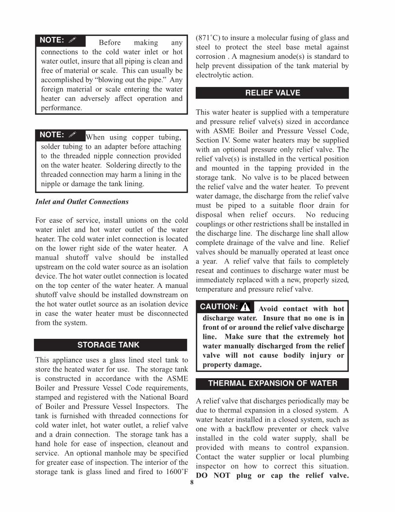
Before making anyconnections to the cold water inlet or hotwater outlet, insure that all piping is clean andfree of material or scale. This can usually beaccomplished by “blowing out the pipe.” Anyforeign material or scale entering the waterheater can adversely affect operation andperformance.
Inlet and Outlet Connections
For ease of service, install unions on the coldwater inlet and hot water outlet of the waterheater. The cold water inlet connection is locatedon the lower right side of the water heater. Amanual shutoff valve should be installedupstream on the cold water source as an isolationdevice. The hot water outlet connection is locatedon the top center of the water heater. A manualshutoff valve should be installed downstream onthe hot water outlet source as an isolation devicein case the water heater must be disconnectedfrom the system.
This appliance uses a glass lined steel tank tostore the heated water for use. The storage tankis constructed in accordance with the ASMEBoiler and Pressure Vessel Code requirements,stamped and registered with the National Boardof Boiler and Pressure Vessel Inspectors. Thetank is furnished with threaded connections forcold water inlet, hot water outlet, a relief valveand a drain connection. The storage tank has ahand hole for ease of inspection, cleanout andservice. An optional manhole may be specifiedfor greater ease of inspection. The interior of thestorage tank is glass lined and fired to 1600˚F
(871˚C) to insure a molecular fusing of glass andsteel to protect the steel base metal againstcorrosion . A magnesium anode(s) is standard tohelp prevent dissipation of the tank material byelectrolytic action.
This water heater is supplied with a temperatureand pressure relief valve(s) sized in accordancewith ASME Boiler and Pressure Vessel Code,Section IV. Some water heaters may be suppliedwith an optional pressure only relief valve. Therelief valve(s) is installed in the vertical positionand mounted in the tapping provided in thestorage tank. No valve is to be placed betweenthe relief valve and the water heater. To preventwater damage, the discharge from the relief valvemust be piped to a suitable floor drain fordisposal when relief occurs. No reducingcouplings or other restrictions shall be installed inthe discharge line. The discharge line shall allowcomplete drainage of the valve and line. Reliefvalves should be manually operated at least oncea year. A relief valve that fails to completelyreseat and continues to discharge water must beimmediately replaced with a new, properly sized,temperature and pressure relief valve.
A relief valve that discharges periodically may bedue to thermal expansion in a closed system. Awater heater installed in a closed system, such asone with a backflow preventer or check valveinstalled in the cold water supply, shall beprovided with means to control expansion.Contact the water supplier or local plumbinginspector on how to correct this situation. DO NOT plug or cap the relief valve.
8
STORAGE TANK
NOTE: �
When using copper tubing,solder tubing to an adapter before attachingto the threaded nipple connection providedon the water heater. Soldering directly to thethreaded connection may harm a lining in thenipple or damage the tank lining.
NOTE: �
RELIEF VALVE
Avoid contact with hotdischarge water. Insure that no one is infront of or around the relief valve dischargeline. Make sure that the extremely hotwater manually discharged from the reliefvalve will not cause bodily injury orproperty damage.
CAUTION:
THERMAL EXPANSION OF WATER
discharge!
Hydrogen gas can be produced in a hot watersystem that has not been used for a long period oftime (generally two weeks or more). Hydrogengas is extremely flammable. To prevent thepossibility of injury under these conditions, werecommend the hot water faucet be open forseveral minutes at a sink close to the water heaterbefore you use any electrical appliance which isconnected to the hot water system. If hydrogen ispresent, there will be an unusual sound such as airescaping through the pipe as the hot water beginsto flow. There should be no smoking or openflames near the faucet at the time it is open.
All installation procedures involving electricpower connection should only be performed by atrained, certified electrician.
9
HINGED DOOR TOELECTRIC CONTROLCOMPARTMENT
ELECTRIC ACCESS
FIG. 11 Electric Power Connections – Electrical Control Panel – Square Models
HINGED DOORTO ELECTRICALCOMPARTMENT
ELECTRICACCESS
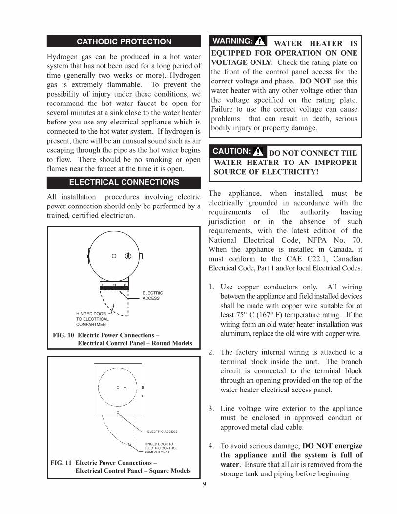
FIG. 10 Electric Power Connections – Electrical Control Panel – Round Models
The appliance, when installed, must be electrically grounded in accordance with the requirements of the authority having jurisdiction or in the absence of such requirements, with the latest edition of the National Electrical Code, NFPA No. 70. When the appliance is installed in Canada, it must conform to the CAE C22.1, Canadian Electrical Code, Part 1 and/or local Electrical Codes.
1. Use copper conductors only. All wiring between the appliance and field installed devices shall be made with copper wire suitable for at least 75° C (167° F) temperature rating. If the wiring from an old water heater installation was aluminum, replace the old wire with copper wire.
2. The factory internal wiring is attached to a terminal block inside the unit. The branch circuit is connected to the terminal block through an opening provided on the top of the water heater electrical access panel.
3. Line voltage wire exterior to the appliance must be enclosed in approved conduit or approved metal clad cable.
4. To avoid serious damage, DO NOT energize the appliance until the system is full of water. Ensure that all air is removed from the storage tank and piping before beginning
CATHODIC PROTECTION
ELECTRICAL CONNECTIONS
WATER HEATER ISEQUIPPED FOR OPERATION ON ONEVOLTAGE ONLY. Check the rating plate onthe front of the control panel access for thecorrect voltage and phase. DO NOT use thiswater heater with any other voltage other thanthe voltage specified on the rating plate.Failure to use the correct voltage can causeproblems that can result in death, seriousbodily injury or property damage.
DO NOT CONNECT THEWATER HEATER TO AN IMPROPERSOURCE OF ELECTRICITY!
CAUTION:
WARNING:
initial operation. Operation of a water heater without a completely filled tank may result in serious damage to the appliance and heating element burn out.
5. The water heater should be connected with a separate grounded branch circuit with over current protection and disconnect switch. The water heater should be grounded in accordance with national and local codes. A ground terminal is provided for ground connection only.
6. Provide the appliance with proper overload protection in the branch circuit. It is suggested that the electrician size the branch circuit at 125 percent of the heater ampere rating and further increase wire size as necessary to compensate for voltage drop in long runs. Branch circuit voltage drop should not exceed 3% at the heater.
7. Voltage applied to the heater should not vary more than +5% to -10% of the model and rating plate marking for satisfactory operation.
8. A wiring diagram is provided with the water heater for the electricians use.
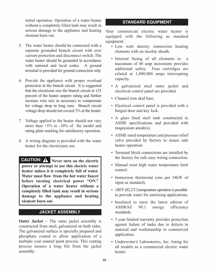
Outer Jacket – The outer jacket assembly isconstructed from steel, galvanized on both sides.The galvanized surface is specially prepared andphosphate coated to allow application of amultiple coat enamel paint process. This coatingprocess insures a long life from the jacketassembly.
Your commercial electric water heater isequipped with the following as standardequipment.
• Low watt density immersion heating elements with an incoloy sheath.
• Internal fusing of all elements in a maximum of 48 amp increments provides additional safety. Fuse cartridges are related at 1,000,000 amps interrupting capacity.
• A galvanized steel outer jacket and electrical control panel are provided.
• Channel iron skid base.
• Electrical control panel is provided with a hinged door and key lock.
• A glass lined steel tank constructed to ASME specifications and provided with magnesium anode(s).
• ASME rated temperature and pressure relief valve provided by factory to insure safe heater operation.
• Terminal block connections are installed by the factory for safe easy wiring connection.
• Manual reset high water temperature limit control.
• Immersion thermostat (one per 54kW of input as standard).
• 180˚F (82.2˚C) temperature operation is possibleto provide water for sanitizing applications.
• Insulated to meet the latest edition of ASHRAE 90.1 energy efficiency standards.
• 3 year limited warranty provides protection against failure of tanks due to defects in material and workmanship in commercial application.
• Underwriter’s Laboratories, Inc. listing for all models as a commercial electric water heater.
10
JACKET ASSEMBLY
Never turn on the electricpower or attempt to use this electric waterheater unless it is completely full of water.Water must flow from the hot water faucetbefore turning electrical power “ON.”Operation of a water heater without acompletely filled tank may result in seriousdamage to the appliance and heatingelement burn out
CAUTION:
STANDARD EQUIPMENT
The following items are available as extra costoptions.
• Electronic low water cut-off prevents energizing of the heater when it is not filledwith water.
• Pilot lights – Monitor on-off cycle of contactors.
• Manual limiting switches with indicating lights to permit heater kW input to be manually limited as desired.
• Temperature and pressure gauges are available installed flush with the jacket to monitor heater performance.
• Electronic step controller modulates power in-put and balances load to demand.
• Safety door interlock prevents opening of access door while heater is energized.
• Shunt trip disconnect provides power disconnect upon a control sensed malfunction.
• Alarm bell provides an audible alarm to warn of various control failures.
• Time clock to control off-on cycles of the heater as programmed by the owner or electric utility requirements.
• Low water pressure switch.
• High water pressure switch.
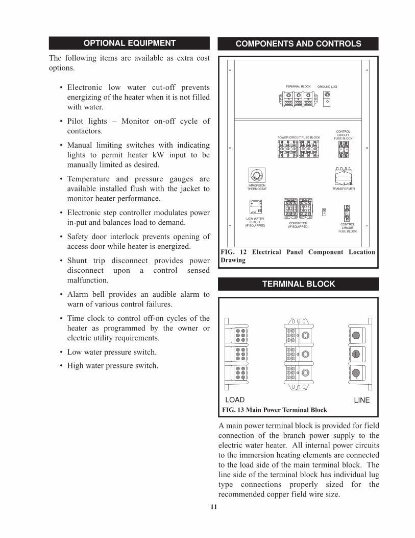
A main power terminal block is provided for fieldconnection of the branch power supply to theelectric water heater. All internal power circuitsto the immersion heating elements are connectedto the load side of the main terminal block. Theline side of the terminal block has individual lugtype connections properly sized for therecommended copper field wire size.
11
OPTIONAL EQUIPMENT COMPONENTS AND CONTROLS
POWER CIRCUIT FUSE BLOCK
IMMERSIONTHERMOSTAT
CONTACTOR(IF EQUIPPED)
LOW WATERCUTOFF
(IF EQUIPPED) CONTROLCIRCUIT
FUSE BLOCK
CONTROLCIRCUIT
FUSE BLOCK
TRANSFORMER
TERMINAL BLOCK GROUND LUG
FIG. 12 Electrical Panel Component LocationDrawing
TERMINAL BLOCK
LOAD LINEFIG. 13 Main Power Terminal Block

Each internal power circuit is fused for safety.Each power circuit to an immersion element isfused at a maximum of 48 amps. Power circuitsmay be fused at lower current levels as needed tobalance current on three phase units. The powercircuit fuses are held by a spring loaded fuseblock rated for the voltage specified to operatethe water heater.
The control circuit is also fused on both theprimary and secondary sides of the control circuittransformer.
The power to the immersion electric heatingelements is switched by a definite purposemagnetic contactor. The contactor is suppliedwith 120 VAC from the control circuit when theimmersion thermostat senses a drop in storedwater temperature below the desired set point. Amagnetic coil in the contactor is energized tocomplete the electrical circuit supplying power tothe immersion heating elements. When thethermostat is satisfied, the contactor coil is de-energized and power to the heating elements isturned off.
CONTROL CIRCUIT TRANSFORMER
A transformer is used to reduce the line voltage to120 VAC for internal control operation. Thetransformer is fused on both the primary andsecondary side. The common side of thesecondary control circuit is grounded. The VArating of the control circuit transformer is basedon the load of the various components in thewater heater control circuit.
12
FIG. 14 Fuse Block with Power Circuit Fuses
FUSE AND FLUE BLOCKS
FIG. 15 Magnetic Contactor
CONTACTORS
CONTROL CIRCUIT TRANSFORMER
HAZARD OF ELECTRICAL SHOCK –Before opening the electrical access panelto adjust the thermostat or servicing thewater heater, make sure the electricalsupply to the water heater is turned “OFF”.Failure to do this could result in death,serious bodily injury or property damage.
WARNING:
FIG. 16 Control Circuit Transformer
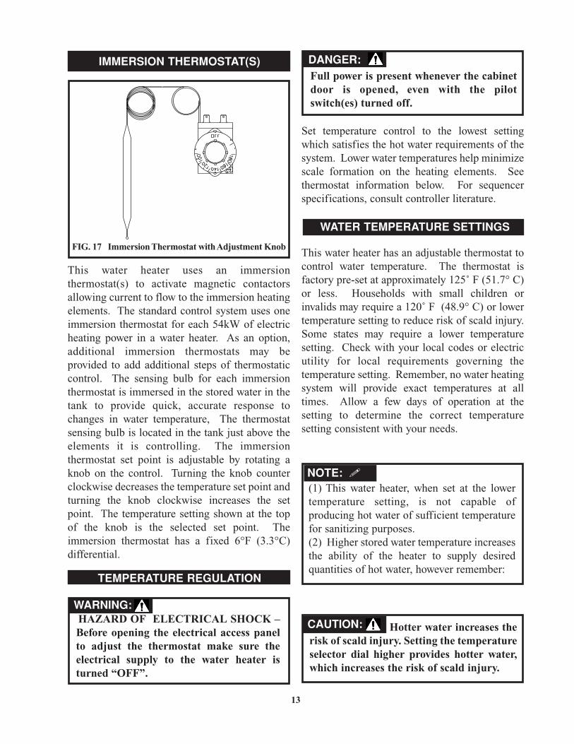
This water heater uses an immersionthermostat(s) to activate magnetic contactorsallowing current to flow to the immersion heatingelements. The standard control system uses oneimmersion thermostat for each 54kW of electricheating power in a water heater. As an option,additional immersion thermostats may beprovided to add additional steps of thermostaticcontrol. The sensing bulb for each immersionthermostat is immersed in the stored water in thetank to provide quick, accurate response tochanges in water temperature, The thermostatsensing bulb is located in the tank just above theelements it is controlling. The immersionthermostat set point is adjustable by rotating aknob on the control. Turning the knob counterclockwise decreases the temperature set point andturning the knob clockwise increases the setpoint. The temperature setting shown at the topof the knob is the selected set point. Theimmersion thermostat has a fixed 6°F (3.3°C)differential.
Set temperature control to the lowest settingwhich satisfies the hot water requirements of thesystem. Lower water temperatures help minimizescale formation on the heating elements. Seethermostat information below. For sequencerspecifications, consult controller literature.
This water heater has an adjustable thermostat tocontrol water temperature. The thermostat isfactory pre-set at approximately 125˚ F (51.7° C)or less. Households with small children orinvalids may require a 120˚ F (48.9° C) or lowertemperature setting to reduce risk of scald injury.Some states may require a lower temperaturesetting. Check with your local codes or electricutility for local requirements governing thetemperature setting. Remember, no water heatingsystem will provide exact temperatures at alltimes. Allow a few days of operation at thesetting to determine the correct temperaturesetting consistent with your needs.
13
WATER TEMPERATURE SETTINGS
TEMPERATURE REGULATION
IMMERSION THERMOSTAT(S)
FIG. 17 Immersion Thermostat with Adjustment Knob
HAZARD OF ELECTRICAL SHOCK –Before opening the electrical access panelto adjust the thermostat make sure theelectrical supply to the water heater isturned “OFF”.
WARNING:
Full power is present whenever the cabinetdoor is opened, even with the pilotswitch(es) turned off.
DANGER:
Hotter water increases therisk of scald injury. Setting the temperatureselector dial higher provides hotter water,which increases the risk of scald injury.
CAUTION:
(1) This water heater, when set at the lowertemperature setting, is not capable ofproducing hot water of sufficient temperaturefor sanitizing purposes.(2) Higher stored water temperature increasesthe ability of the heater to supply desiredquantities of hot water, however remember:
NOTE: �
The maximum temperaturesetpoint that should be set for theImmersion Thermostats or programmedinto the Electronic Temperature ControlSequencer is 190° F ( 88° C)
Always close the electrical control panel doorafter making a temperature adjustment. Turn onelectricity.
1. Turn “OFF” the electrical power to the water heater. If the power disconnect point is out of sight, lock it in the open (“OFF”) position and tag to prevent unexpected applicationof power.
2. Open the water heater’s electrical access panel.
3. Adjust each immersion thermostat to the desired temperature setting by turning the adjusting knob. Each thermostat will be factory pre-set to approximately 125° F (51.7° C) or less as shipped.
4. Close the water heater’s electrical access panel.
5. Turn “ON” the electrical power to thewater heater.
ELECTRONIC TEMPERATURECONTROL SEQUENCER
14
CAUTION:
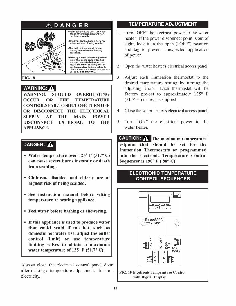
TEMPERATURE ADJUSTMENTD A N G E R
HOT!
BURN
• Water temperature over 125˚F can cause severe burns instantly or death from scalds.
• Children, disabled and elderly are at highest risk of being scalded.
• See instruction manual before setting temperature at heating appliance.
• If this appliance is used to produce water that could scald if too hot, such as domestic hot water use, adjust the outlet control (limit) or use temperature limiting valves to obtain a maximum water temperature of 125˚F. SEE MANUAL.
FIG. 18
WARNING: SHOULD OVERHEATINGOCCUR OR THE TEMPERATURECONTROLS FAIL TO SHUT OFF,TURN OFFOR DISCONNECT THE ELECTRICALSUPPLY AT THE MAIN POWERDISCONNECT EXTERNAL TO THEAPPLIANCE.
WARNING:
• Water temperature over 125˚ F (51.7°C) can cause severe burns instantly or death from scalding.
• Children, disabled and elderly are at highest risk of being scalded.
• See instruction manual before setting temperature at heating appliance.
• Feel water before bathing or showering.
• If this appliance is used to produce water that could scald if too hot, such as domestic hot water use, adjust the outlet control (limit) or use temperature limiting valves to obtain a maximumwater temperature of 125˚ F (51.7° C).
ELECTRONIC TEMPERATURECONTROL SEQUENCER
DANGER:
FIG. 19 Electronic Temperature Controlwith Digital Display
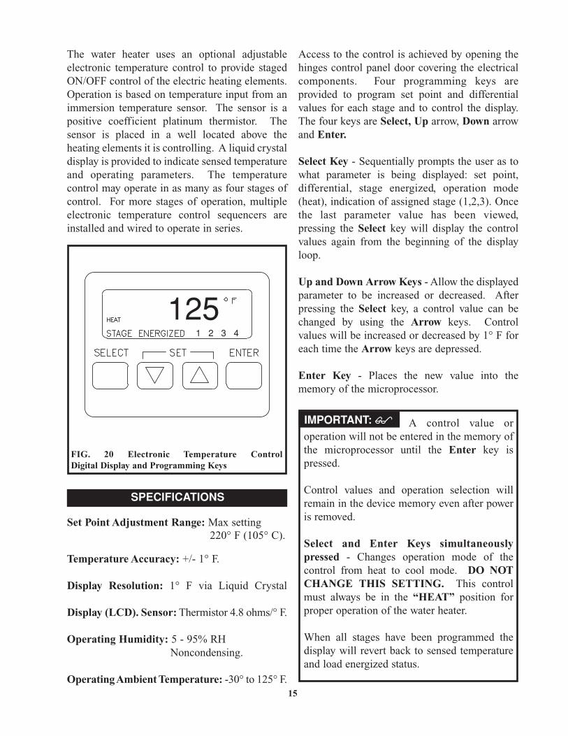
The water heater uses an optional adjustableelectronic temperature control to provide stagedON/OFF control of the electric heating elements.Operation is based on temperature input from animmersion temperature sensor. The sensor is apositive coefficient platinum thermistor. Thesensor is placed in a well located above theheating elements it is controlling. A liquid crystaldisplay is provided to indicate sensed temperatureand operating parameters. The temperaturecontrol may operate in as many as four stages ofcontrol. For more stages of operation, multipleelectronic temperature control sequencers areinstalled and wired to operate in series.
Set Point Adjustment Range: Max setting220° F (105° C).
Temperature Accuracy: +/- 1° F.
Display Resolution: 1° F via Liquid Crystal
Display (LCD). Sensor: Thermistor 4.8 ohms/° F.
Operating Humidity: 5 - 95% RH Noncondensing.
Operating Ambient Temperature: -30° to 125° F.
Access to the control is achieved by opening thehinges control panel door covering the electricalcomponents. Four programming keys areprovided to program set point and differentialvalues for each stage and to control the display.The four keys are Select, Up arrow, Down arrowand Enter.
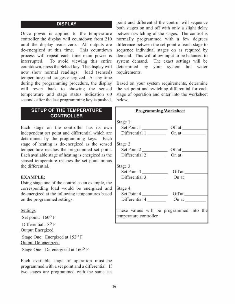
Select Key - Sequentially prompts the user as towhat parameter is being displayed: set point,differential, stage energized, operation mode(heat), indication of assigned stage (1,2,3). Oncethe last parameter value has been viewed,pressing the Select key will display the controlvalues again from the beginning of the displayloop.
Up and Down Arrow Keys - Allow the displayedparameter to be increased or decreased. Afterpressing the Select key, a control value can bechanged by using the Arrow keys. Controlvalues will be increased or decreased by 1° F foreach time the Arrow keys are depressed.
Enter Key - Places the new value into thememory of the microprocessor.
15
1251 2 3 4
FIG. 20 Electronic Temperature ControlDigital Display and Programming Keys
SPECIFICATIONS
A control value oroperation will not be entered in the memory ofthe microprocessor until the Enter key ispressed.
Control values and operation selection willremain in the device memory even after poweris removed.
Select and Enter Keys simultaneouslypressed - Changes operation mode of thecontrol from heat to cool mode. DO NOTCHANGE THIS SETTING. This controlmust always be in the “HEAT” position forproper operation of the water heater.
When all stages have been programmed thedisplay will revert back to sensed temperatureand load energized status.
IMPORTANT:��
Once power is applied to the temperaturecontroller the display will countdown from 210until the display reads zero. All outputs arede-energized at this time. This countdownprocess will repeat each time main power isinterrupted. To avoid viewing this entirecountdown, press the Select key. The display willnow show normal readings: load (sensed)temperature and stages energized. At any timeduring the programming procedure, the displaywill revert back to showing the sensedtemperature and stage status indication 60seconds after the last programming key is pushed.
Each stage on the controller has its ownindependent set point and differential which aredetermined by the programming keys. Eachstage of heating is de-energized as the sensedtemperature reaches the programmed set point.Each available stage of heating is energized as thesensed temperature reaches the set point minusthe differential.
EXAMPLE:Using stage one of the control as an example, thecorresponding load would be energized andde-energized at the following temperatures basedon the programmed settings.
Settings
Set point: 160o F
Differential: 8o FOutput Energized
Stage One: Energized at 152o FOutput De-energized
Stage One: De-energized at 160o F
Each available stage of operation must beprogrammed with a set point and a differential. Iftwo stages are programmed with the same set
point and differential the control will sequenceboth stages on and off with only a slight delaybetween switching of the stages. The control isnormally programmed with a few degreesdifference between the set point of each stage tosequence individual stages on as required bydemand. This will allow input to be balanced tosystem demand. The exact settings will bedetermined by your system hot waterrequirements.
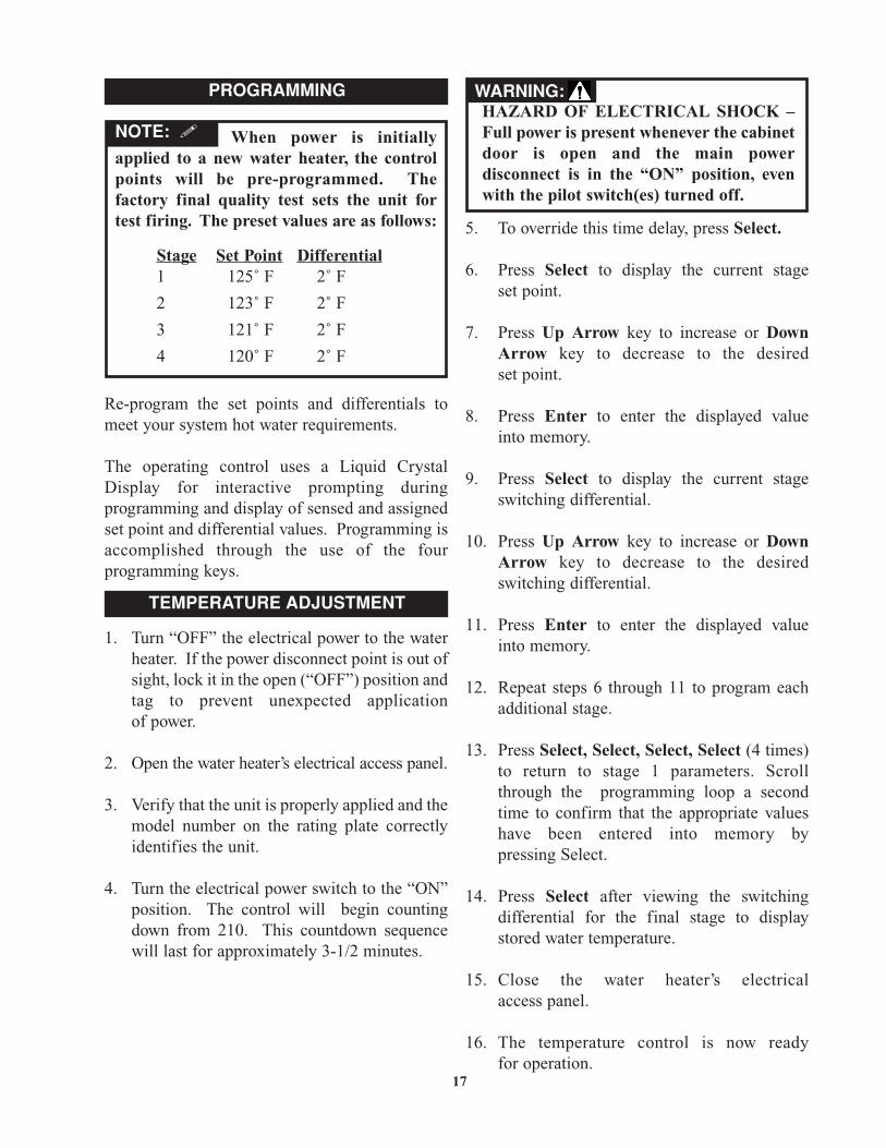
Based on your system requirements, determinethe set point and switching differential for eachstage of operation and enter into the worksheetbelow.
Programming Worksheet
Stage 1:Set Point 1 ___________ Off at ___________Differential 1 ________ On at __________
Stage 2:Set Point 2 ___________ Off at ___________Differential 2 ________ On at __________
Stage 3:Set Point 3 ___________ Off at __________Differential 3 ________ On at _________
Stage 4:Set Point 4 ___________ Off at __________Differential 4 ________ On at _________
These values will be programmed into thetemperature controller.
16
DISPLAY
SETUP OF THE TEMPERATURECONTROLLER
Stage Set Point Differential1 125˚ F 2˚ F
2 123˚ F 2˚ F
3 121˚ F 2˚ F
4 120˚ F 2˚ F
Re-program the set points and differentials tomeet your system hot water requirements.
The operating control uses a Liquid CrystalDisplay for interactive prompting duringprogramming and display of sensed and assignedset point and differential values. Programming isaccomplished through the use of the fourprogramming keys.
1. Turn “OFF” the electrical power to the water heater. If the power disconnect point is out of sight, lock it in the open (“OFF”) position and tag to prevent unexpected applicationof power.
2. Open the water heater’s electrical access panel.
3. Verify that the unit is properly applied and the model number on the rating plate correctly identifies the unit.
4. Turn the electrical power switch to the “ON” position. The control will begin counting down from 210. This countdown sequence will last for approximately 3-1/2 minutes.
5. To override this time delay, press Select.
6. Press Select to display the current stageset point.
7. Press Up Arrow key to increase or DownArrow key to decrease to the desiredset point.
8. Press Enter to enter the displayed valueinto memory.
9. Press Select to display the current stage switching differential.
10. Press Up Arrow key to increase or DownArrow key to decrease to the desired switching differential.
11. Press Enter to enter the displayed valueinto memory.
12. Repeat steps 6 through 11 to program each additional stage.
13. Press Select, Select, Select, Select (4 times) to return to stage 1 parameters. Scroll through the programming loop a second time to confirm that the appropriate values have been entered into memory bypressing Select.
14. Press Select after viewing the switching differential for the final stage to display stored water temperature.
15. Close the water heater’s electricalaccess panel.
16. The temperature control is now readyfor operation.
17
When power is initiallyapplied to a new water heater, the controlpoints will be pre-programmed. Thefactory final quality test sets the unit fortest firing. The preset values are as follows:
NOTE: �
PROGRAMMING
TEMPERATURE ADJUSTMENT
HAZARD OF ELECTRICAL SHOCK –Full power is present whenever the cabinetdoor is open and the main powerdisconnect is in the “ON” position, evenwith the pilot switch(es) turned off.
WARNING:
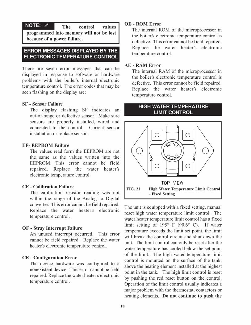
FIG. 21 High Water Temperature Limit Control- Fixed Setting
ERROR MESSAGES DISPLAYED BY THEELECTRONIC TEMPERATURE CONTROL
There are seven error messages that can bedisplayed in response to software or hardwareproblems with the boiler’s internal electronictemperature control. The error codes that may beseen flashing on the display are:
SF - Sensor FailureThe display flashing SF indicates anout-of-range or defective sensor. Make sure sensors are properly installed, wired and connected to the control. Correct sensor installation or replace sensor.
EF- EEPROM FailureThe values read form the EEPROM are not the same as the values written into the EEPROM. This error cannot be field repaired. Replace the water heater’s electronic temperature control.
CF - Calibration FailureThe calibration resistor reading was not within the range of the Analog to Digital converter. This error cannot be field repaired. Replace the water heater’s electronic temperature control.
OF - Stray Interrupt FailureAn unused interrupt occurred. This error cannot be field repaired. Replace the water heater’s electronic temperature control.
CE - Configuration ErrorThe device hardware was configured to a nonexistent device. This error cannot be fieldrepaired. Replace the water heater’s electronic temperature control.
OE - ROM ErrorThe internal ROM of the microprocessor in the boiler’s electronic temperature control is defective. This error cannot be field repaired. Replace the water heater’s electronic temperature control.
AE - RAM ErrorThe internal RAM of the microprocessor in the boiler’s electronic temperature control is defective. This error cannot be field repaired. Replace the water heater’s electronic temperature control.
The unit is equipped with a fixed setting, manualreset high water temperature limit control. Thewater heater temperature limit control has a fixedlimit setting of 195° F (90.6° C). If watertemperature exceeds the limit set point, the limitwill break the control circuit and shut down theunit. The limit control can only be reset after thewater temperature has cooled below the set pointof the limit. The high water temperature limitcontrol is mounted on the surface of the tank,above the heating element installed at the highestpoint in the tank. The high limit control is resetby pushing the red reset button on the control.Operation of the limit control usually indicates amajor problem with the thermostat, contactors orheating elements. Do not continue to push the
18
HIGH WATER TEMPERATURELIMIT CONTROL
The control valuesprogrammed into memory will not be lostbecause of a power failure.
NOTE: �
The high limit control will notreset until the water temperature hasdropped below the set point of the high limit.
reset multiple times. The source of the problemmust be found and corrected to insure properoperation. The limit control is covered with aninsulation blanket which must be removed topush the red reset button. The blanket ofinsulation must be replaced before the power isturned on and the water heater is returned toservice.
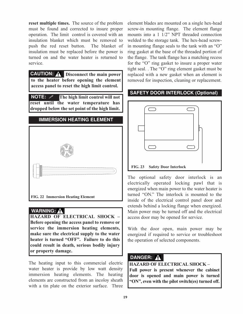
The heating input to this commercial electricwater heater is provide by low watt densityimmersion heating elements. The heatingelements are constructed from an incoloy sheathwith a tin plate on the exterior surface. Three
element blades are mounted on a single hex-headscrew-in mounting flange. The element flangemounts into a 1 1/2” NPT threaded connectionwelded to the storage tank. The hex-head screw-in mounting flange seals to the tank with an “O”ring gasket at the base of the threaded portion ofthe flange. The tank flange has a matching recessfor the “O” ring gasket to insure a proper watertight seal. . The “O” ring element gasket must bereplaced with a new gasket when an element isremoved for inspection, cleaning or replacement.
The optional safety door interlock is anelectrically operated locking pawl that isenergized when main power to the water heater isturned “ON.” The interlock is mounted to theinside of the electrical control panel door andextends behind a locking flange when energized.Main power may be turned off and the electricalaccess door may be opened for service.
With the door open, main power may beenergized if required to service or troubleshootthe operation of selected components.
19
SAFETY DOOR INTERLOCK (Optional)
FIG. 22 Immersion Heating Element
NOTE: �
IMMERSION HEATING ELEMENT
HAZARD OF ELECTRICAL SHOCK –Before opening the access panel to remove orservice the immersion heating elements,make sure the electrical supply to the waterheater is turned “OFF”. Failure to do thiscould result in death, serious bodily injuryor property damage.
WARNING:
Disconnect the main powerto the heater before opening the elementaccess panel to reset the high limit control.
CAUTION:
FIG. 23 Safety Door Interlock
HAZARD OF ELECTRICAL SHOCK –Full power is present whenever the cabinetdoor is opened and main power is turned“ON”, even with the pilot switch(es) turned off.
DANGER:

This water heater may be equipped with anoptional electronic low water cut-off installed atthe factory. This low water cut-off device uses awater level sensing probe located above theheating element installed in the highest point inthe storage tank. If the internal water level dropsbelow this point, the low water cut-off will shutdown operation of the heating elements. Anelectronic type low water cut-off is available as afactory supplied option on all models. Theoptional electronic low water cut-off has an LEDlocated on the main circuit board. This LED willbe illuminated and the control circuit will becompleted between the common and normallyopen contacts on the circuit board when thesensing probe is below the water level in thestorage tank. An optional manual reset functionand test button is available on the electronic lowwater cut-off. The operation of a low water cut-off should be inspected every six months.
A low water pressure switch is available as anoption on this water heater. A water pressureswitch is used to monitor the water pressure in thewater heater storage tank. If the water pressuredrops below an adjustable set point, the controlcircuit is opened and operation of the waterheater is shut down. The low water pressureswitch may be specified with either a auto-resetfunction or a manual reset function on low waterpressure.
A high water pressure switch is available as anoption on this water heater. A water pressureswitch is used to monitor the water pressure in thewater heater storage tank. If the water pressurerises above an adjustable set point, the controlcircuit is opened and operation of the waterheater is shut down. The low water pressureswitch may be specified with either a auto-resetfunction or a manual reset function on high waterpressure.
As an option, a switch or multiple switches may beprovided to interrupt the 120 VAC control circuitfeed to the contactor coil or coils from theimmersion heating thermostat(s). This switch maybe used to manually turn off a portion of the heatingelement input. This feature may be used to reduce
20
Control Board
Probe
LED
FIG. 24 Electronic Low Water Cut-off Control
LOW WATER PRESSURE SWITCH(Optional)
FIG. 25 Low Water Pressure Switch
LOW WATER CUTOFF (Optional)
HIGH WATER PRESSURE SWITCH(Optional)
FIG. 26 High Water Pressure Switch
MANUAL LIMITING SWITCHES (Optional)
electrical input of the water heater in the summermonths when ground water temperatures arewarmer and full electrical input from theimmersion heating elements is not required. Thewater heater may be restored to full input bymoving the switches to the “ON” position.
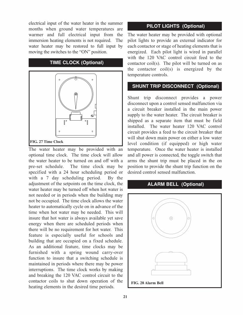
The water heater may be provided with anoptional time clock. The time clock will allowthe water heater to be turned on and off with apre-set schedule. The time clock may bespecified with a 24 hour scheduling period orwith a 7 day scheduling period. By theadjustment of the setpoints on the time clock, thewater heater may be turned off when hot water isnot needed or in periods when the building maynot be occupied. The time clock allows the waterheater to automatically cycle on in advance of thetime when hot water may be needed. This willinsure that hot water is always available yet saveenergy when there are scheduled periods whenthere will be no requirement for hot water. Thisfeature is especially useful for schools andbuilding that are occupied on a fixed schedule.As an additional feature, time clocks may befurnished with a spring wound carry-overfunction to insure that a switching schedule ismaintained in periods where there may be powerinterruptions. The time clock works by makingand breaking the 120 VAC control circuit to thecontactor coils to shut down operation of theheating elements in the desired time periods.
The water heater may be provided with optionalpilot lights to provide an external indicator foreach contactor or stage of heating elements that isenergized. Each pilot light is wired in parallelwith the 120 VAC control circuit feed to thecontactor coil(s). The pilot will be turned on asthe contactor coil(s) is energized by thetemperature controls.
Shunt trip disconnect provides a powerdisconnect upon a control sensed malfunction viaa circuit breaker installed in the main powersupply to the water heater. The circuit breaker isshipped as a separate item that must be fieldinstalled. The water heater 120 VAC controlcircuit provides a feed to the circuit breaker thatwill shut down main power on either a low waterlevel condition (if equipped) or high watertemperature. Once the water heater is installedand all power is connected, the toggle switch thatarms the shunt trip must be placed in the onposition to provide the shunt trip function on thedesired control sensed malfunction.
21
FIG. 27 Time Clock
TIME CLOCK (Optional)
PILOT LIGHTS (Optional)
SHUNT TRIP DISCONNECT (Optional)
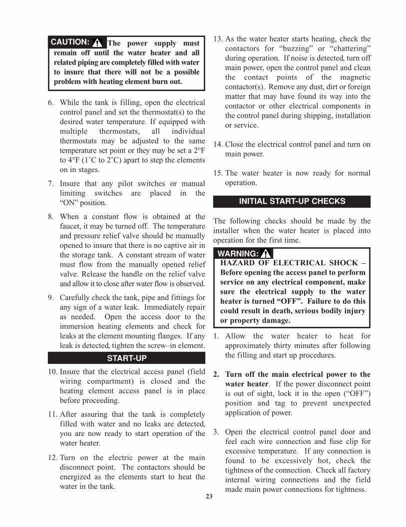
ALARM BELL (Optional)
FIG. 28 Alarm Bell

The cold water supply must beleft in the open position when the waterheater is in use.
An alarm bell with silencing switch is available asan option on this water heater. The alarm bell canbe used to provide an audible indication of acontrol sensed malfunction. The user mustspecify the safety function or multiple safetyfunctions that the alarm bell will sound on whenthe water heater is ordered from the factory. Thealarm bell typically is used to indicate a low watercondition or a high water temperature condition.The alarm is furnished with a silencing switch toturn off the audible alarm while trouble shootinga control sensed malfunction that is indicated byan audible alarm. Once the control sensedmalfunction is corrected, the silencing switchmust be returned to the “ON” position tore-establish the audible alarm function.
Never operate the heating elements withoutbeing certain the water heater is filled withwater and a temperature and pressure reliefvalve is installed in the relief valve opening ontop of the heater.
The pilot switch(es) (if equipped) mounted on thecontrol cabinet permit the heater to be turned on and offwithout having to operate the electrical disconnectswitch. The pilot switch interrupts only the 120 VACcontrol circuit in the water heater. Full power is stillpresent at the terminal block, fuses and contactors.
A relief valve that discharges periodically may bedue to thermal expansion in a closed system.Many water systems are equipped with pressurereducing valves, check valves or back flowpreventers which may cause the water system tobe closed. As water is heated it will expand involume due to thermal expansion. The systemmust make allowance for this expansion. If anexpansion tank is not provided in the system,water pressure may increase to the point where
the water heater’s temperature and pressure reliefvalve opens to relieve the excess pressure. Thetemperature and pressure relief valve is notintended for the constant relief of thermalexpansion. This is an unacceptable condition andmust be corrected. Do not plug or cap the reliefvalve discharge! A properly sized expansiontank is typically installed in the potable watersystem to relieve the pressure built up by thermalexpansion of heated water. Consult your localplumbing contractor and plumbing wholesaler forassistance in properly selecting an expansion tankfor your system.
As the water heater operates, there may be noisesgenerated by the expansion and contraction of themetal parts of the water heater and related piping.These noises may occur during periods of heat upor cool down. They do not represent harmful ordangerous conditions.
1. Insure that the electrical power to the water heater is in the “OFF” position. If the power disconnect point is out of sight, lock it in the open (“OFF”) position and tag to prevent unexpected application of power.
2. Close the water heater drain valve(s).
3. Open a nearby hot water faucet to allow the air in the system to escape as the tank fills.
4. Fully open the cold water inlet valve to the water heater to begin filling the heater and piping.
5. Check the nearby hot water faucet to verify that air is exiting the tank as it fills with water. Allow water to run until a constant flow is obtained at the faucet. This will insure that all air is purged from the system.
22
START-UP PROCEDURE
Full power is present whenever the cabinetdoor is opened, even with the pilotswitch(es) turned off.
DANGER:
THERMAL EXPANSION OF WATER
FILLING THE WATER HEATER
NOTE: �
6. While the tank is filling, open the electrical control panel and set the thermostat(s) to the desired water temperature. If equipped with multiple thermostats, all individual thermostats may be adjusted to the same temperature set point or they may be set a 2°F to 4°F (1˚C to 2˚C) apart to step the elements on in stages.
7. Insure that any pilot switches or manual limiting switches are placed in the“ON” position.
8. When a constant flow is obtained at the faucet, it may be turned off. The temperature and pressure relief valve should be manually opened to insure that there is no captive air in the storage tank. A constant stream of water must flow from the manually opened relief valve. Release the handle on the relief valve and allow it to close after water flow is observed.
9. Carefully check the tank, pipe and fittings for any sign of a water leak. Immediately repair as needed. Open the access door to the immersion heating elements and check for leaks at the element mounting flanges. If any leak is detected, tighten the screw–in element.
10. Insure that the electrical access panel (field wiring compartment) is closed and the heating element access panel is in place before proceeding.
11. After assuring that the tank is completely filled with water and no leaks are detected, you are now ready to start operation of the water heater.
12. Turn on the electric power at the main disconnect point. The contactors should be energized as the elements start to heat the water in the tank.
23
START-UP
13. As the water heater starts heating, check the contactors for “buzzing” or “chattering” during operation. If noise is detected, turn offmain power, open the control panel and clean the contact points of the magnetic contactor(s). Remove any dust, dirt or foreign matter that may have found its way into the contactor or other electrical components in the control panel during shipping, installation or service.
14. Close the electrical control panel and turn on main power.
15. The water heater is now ready for normal operation.
The following checks should be made by theinstaller when the water heater is placed intooperation for the first time.
1. Allow the water heater to heat for approximately thirty minutes after following the filling and start up procedures.
2. Turn off the main electrical power to the water heater. If the power disconnect point is out of sight, lock it in the open (“OFF”) position and tag to prevent unexpected application of power.
3. Open the electrical control panel door and feel each wire connection and fuse clip for excessive temperature. If any connection is found to be excessively hot, check the tightness of the connection. Check all factory internal wiring connections and the field made main power connections for tightness.
INITIAL START-UP CHECKS
The power supply mustremain off until the water heater and allrelated piping are completely filled with waterto insure that there will not be a possibleproblem with heating element burn out.
CAUTION:
HAZARD OF ELECTRICAL SHOCK –Before opening the access panel to performservice on any electrical component, makesure the electrical supply to the waterheater is turned “OFF”. Failure to do thiscould result in death, serious bodily injuryor property damage.
WARNING:

4. Close and lock the electrical control panel door.
5. Turn on the main electrical power to thewater heater.
6. Temperature control and contactor operation should be checked by allowing the water heater to come up to temperature and shut off automatically.
7. The water heater is now ready continuous normal operation.
Draining the Water Heater
1. Turn off the main electrical power to the water heater. If the power disconnect point is out of sight, lock it in the open (“OFF”) position and tag to prevent unexpected application of power.
2. Turn the valve in the water heater’s cold water supply to the closed or “OFF” position.
3. Turn the valve in the water heater’s hot water outlet to the closed or “OFF” position.
4. Manually open the temperature and pressure relief valve to remove any pressure from the storage tank.
5. Allow the system to cool and then open the drain valve to empty the storage tank. It will be necessary to manually hold the temperature and pressure relief valve in the open position to break the vacuum in the tank and allow it to vent and drain. Insure that the water heater drain is routed to a properly sizedfloor drain to allow the water to be removed from the tank. If a floor drain is not available, a hose may be attached to the water heater drain to take the water outdoors.
6. The water heater is now shut down and ready for service or maintenance.
7. Follow the filling and start up procedure to place the water heater back into service.
Listed below are items that must be checked toinsure safe reliable operations. Verify properoperation after servicing.
The temperature and pressure relief valve(s)should be manually operated at least once a year.A relief valve that fails to completely reseat aftermanual operation and continues to dischargewater must be immediately replaced with a new,properly sized, temperature and pressure reliefvalve.
The relief valve(s) should be installed in thevertical position and mounted in the tappingprovided in the storage tank. No valve should beplaced between the relief valve, and the waterheater. To prevent water damage, the dischargefrom the relief valve must be piped to a suitablefloor drain for disposal when relief occurs. Noreducing couplings or other restrictions shall beinstalled in the discharge line. The discharge lineshall allow complete drainage of the valve andline. The discharge line from the relief valve
24
SHUTDOWN PROCEDURE
Any water discharged fromthe manually opened relief valve may be hotand cause a scald injury.
CAUTION:
MAINTENANCE
WARNING: HAZARD OF ELECTRICAL SHOCK –Before opening the access panel to performservice on any electrical component, makesure the electrical supply to the waterheater is turned “OFF”. Failure to do thiscould result in death, serious bodily injuryor property damage.
Label all wires prior todisconnection when servicing controls.Wiring errors can cause improper anddangerous operation.
CAUTION:
TEMPERATURE AND PRESSURERELIEF VALVE OPERATION

should be metallic pipe or a high temperatureplastic pipe (CPVC, etc.) to insure that hot waterflow will not damage the discharge piping fromthe relief valve.
In hard water areas, water treatment should beused to reduce the introduction of minerals to thesystem. Minerals in the water can collect in thestorage tank and on the immersion heatingelements causing noise on operation. Excessivebuild up of minerals on the surface of the heatingelements can reduce the service life of theelements and lead to a non-warrantable failure.
Proper operation of this electric water heater isbased on heating potable water with a hardness of5 to 25 grains per gallon and a total dissolvedsolids not exceeding 350 PPM. Consult themanufacturer when heating potable waterexceeding these specifications. Heating of highhardness and/or high total dissolved solids watermay require frequent cleaning of the storage tankand heating elements to achieve proper operation.The higher the level of dissolved solids or waterhardness, the faster the dissolved minerals in thewater will precipitate out and form scale depositson the heating elements and in the storage tank.The level of scale formation is also acceleratedas stored water temperature increases. Water witha hardness of less than 5 grains per gallon willusually have a low pH which can be aggressiveand corrosive causing non-warrantable damage tothe storage tank, heating elements and associatedpiping. Corrosion due to water chemistrygenerally shows up first in the hot water systembecause heated water increases the rate ofcorrosive chemical reactions.
25
Water heater maintenance includes periodic tankflushing, cleaning and removal of lime scale fromthe heating elements. Where used, the waterheating system circulating pump should be oiled.
1. Turn off main power at the electrical disconnect switch.
2. Open the drain valve. Allow water to flow until it runs clean.
3. Close the drain valve when finished flushing.
4. Turn on the electrical disconnect switch(after filling).
Water born impurities consist of dissolvedminerals which precipitate out of the heated waterand fine particles of soil and sand which settle outand form a layer of sediment on the bottom of thetank. In time, if not removed, the level ofsediment might reach the heating elements.
For convenience, sediment removal and elementlime scale removal should be performed at thesame time as follows:
Sediment and Lime Scale Removal
Sediment and lime scale accumulation on the heating elements is a normal condition common to all immersion type elements. Factorswhich affect the amount of this formation are:
1. Amount of hot water used. As the volume of water increases, more scale results.
2. Water temperature. As the temperature of the water is increased, more scale is deposited on the elements.
3. Characteristics of water supply. Regardless of water treatment, the elements should be examined regularly.
Avoid contact with hotdischarge water. Insure that no one is infront of or around the relief valvedischarge line. Make sure that theextremely hot water manually dischargedfrom the relief valve will not cause bodilyinjury or property damage.
CAUTION:
WATER CHEMISTRY
FLUSHING THE STORAGE TANK
SEDIMENT REMOVAL

All gaskets on disassembledclean-out openings must be
replaced with new gaskets on re-assembly.Gaskets are available from your distributor.
Scale accumulation in the bottom of the storagetank may be removed by turning off main powerand draining the tank. Once all water is removed,the hand hole access can be removed. This willallow large accumulations of scale to be cleanedfrom the bottom of the tank.
Water scale accumulations on the immersionheating element reduce the ability of the elementsto heat water and may cause noise to occur duringoperation. It is recommended that a heatingelement be removed at least once a year forexamination. If it is scaled, all of the elementsshould be removed and cleaned. The elementgasket must be replaced when the element isremoved for cleaning.
Small accumulations of lime scale may beremoved with a stiff bristle brush. Severeaccumulations of lime scale should be removedby dissolving the accumulation in a commercialdelimer. Do not use muratic or hydrochloric acidbase deliming solutions to remove lime scalefrom the elements. Do not pour delimer intotank. Deliming solutions may damage theglass lined interior of the tank
1. Drain the heater following “SHUTDOWN PROCEDURE” instructions.
2. On some high kW input models it is necessary to remove a side panel to gain access to the exposed ends of the elements which are not accessible through the front element access door.
3. Disconnect the wires attached to the element terminals. Try not to disturb the wiring unnecessarily and reconnection will be easier.
4. Loosen the screw-in element flange with a socket and breaker bar. Do not use an impact gun (air or electric) to remove the element flanges from the tank. Mark the location of each element in the tank openings so they may be returned to their original position.
5. Remove the elements from the opening with a twisting, pulling action if the elements are scaled beyond the size of the tank flange openings. Brush loose scale from elements.
6. Place scaled ends of heating elements into a delimer solution and allow scale to dissolve.Do not permit delimer or water to contact heating element electrical terminals.
7. Flush clean ends of elements with water when deliming or cleaning is completed.
8. Clean remaining gasket recess on eachscrew-in element flange. Do not reuse element gaskets.
9. Install a new gasket on each element. Install element into the tank opening where it was originally installed. Tighten the flange with the socket and breaker bar used to removethe element.
10. Attach wires to element terminals from which they were removed.
11. Follow “FILLING THE WATER HEATER” instructions to restore hot water service. Check for water leaks around elements and proper operation when heater is filled.
26
NOTE: �
Keep all delimers away from anode rods toprevent the formation of flammable andexplosive gas.
DANGER:

27
TROUBLE SHOOTING
ChecklistBefore calling for service, check the followingpoints to see if the cause of trouble can beidentified and corrected. Reviewing this checklistmay eliminate the need of a service call andquickly restore hot water service.
Not enough or no hot water
1. Ensure that the electrical disconnect switch serving the water heater is in the “ON” position. The pilot switch(es) on the cabinet should also be in the on position. In some areas, water heater electrical service may be limited by the power company. If the heater operates on a controlled circuit, heater recovery may be affected.
2. Check the fuses. The electrical disconnect switch usually contains fuses. The water heater has fuses located behind the cabinet front door. When replacing internal fuses in the water heater control panel, insure that the same type and size of fuse is used.
3. If the water was excessively hot and is now cold, the manual reset high limit mayhave operated.
To reset, turn off electricity and push the reset button. The high limit is located above the upper most heating element in the storage tank. On some high input models additional hi limits may be located behind the side access panel. Repeat operation of the high temperature cut-off should be investigated by your mechanical contractor or by a qualified technician. A contactor or thermostat may be malfunctioning.
4. The capacity of the heater may have been exceeded by a large demand for hot water. Large demands require a recovery period to restore water temperature.
5. Cold incoming water temperature will lengthen the time required to heat water to the desired temperature. If the heater was installed in the summer when incoming water temperature was warm, colder ground water in the winter months can create the effect of less hot water.
6. Look for wasted hot water and leaking or open hot water faucets.
7. Sediment or lime scale may be affecting water heater operation. Refer to “Maintenance”for details.
Water is too hot
Refer to “Temperature Regulation” and reset thethermostat setpoint to a lower temperature thatwill meet requirements for hot water
Water heater makes sounds
1. Sediment or lime scale accumulation on the elements causes sizzling and hissing noises,when the heater is operating. If this occurs, the tank bottom and elements should be cleaned. Refer to “MAINTENANCE”for details.
2. Some of the electrical components of the water make sounds which are normal. Contactors will “click” or snap as the heater starts and stops. Transformers and contactors often hum.
Water leakage is suspected
1. Check to see if the drain valve istightly closed.
2. The apparent leakage may be condensation which forms on cool surfaces of the heater and piping.
3. If the outlet of the relief valve if leaking, it may represent:
a. Excessive water pressure.b. Excessive water temperature.c. Faulty relief valve.
CP-5M-5/02-Reprinted in U.S.A.
Excessive water pressure is not the most commoncause of relief valve leakage. It is often caused bya “closed system.” A check valve, back flowpreventer or pressure reducing valve, in the inletsystem will not permit the expanded hot watervolume to equalize pressure with the main. Arelief valve must release this water or the waterheater and plumbing system will be damaged.
When such a condition is encountered, localcodes or inspection agency should be consulted todetermine which of the following procedures isacceptable in your area.
• Installation of an expansion tank.• Removal of the check valve.
4. Examine the flange area of the elements for gasket leakage. Tighten the screw-in flange or, if necessary, follow the “Water and Lime Scale Removal” procedure to remove the element and replace the “O” ring gaskets that seal each element.
1. Place the water heater electrical disconnect switch on the “OFF” position.
2. Contact your mechanical contractor or service technician.
28
IF YOU CANNOT IDENTIFY ORCORRECT THE SOURCE OF
MALFUNCTION: