Embed Size (px)
Citation preview
Commercial Electric Service
Handbook
January 2011

Updated January 2011
P.O. Box 8900 • Vancouver, WA 98668 • 360-992-8558
CONTACTS
Clark Public Utilities:
Website . . . . . . . . . . . . . . . . . . . . . . . . . . . . . . . . . . . . . . . . . . . www.ClarkPublicUtilities.com
Construction Services department (To initiate a new service, service upgrade or request a meter unlock) . . . . . . . . . . . . . . . . . . . . . . . . (360) 992-8558
Operations department (To request a standby or for questions on jobs that are inspected, backfilled and ready to be scheduled) . . . . . . . . (360) 992-8839
Customer Service department (For general billing questions about existing electric or water accounts) . . . . . . . . . . . . . . . . . . . . . . . . . . . . . . (360) 992-3000
Note your job number and the name of your Clark Public Utilities representative for quick reference:
Job number
Utility representative name
Phone number/e-mail
Other:
“Call Before You Dig” number (underground utilities locating service) . . . . . . . . . . . . . . . . . . . . . 811 or 1-800-424-5555
Washington State Department of Labor and Industries• To obtain an electrical permit . . . . . . . . . . . . . . . . . . . . . . . . . . . . . . . . . . (360) 896-2300• Questions about a permit or code. . . . . . . . . . . . . . . . . . . . . . . . . . . . . . . (360) 896-2360• To request an electrical inspection . . . . . . . . . . . . . . . . . . . . . . . . . . . . . . (360) 896-2350
City of Vancouver• To obtain an electrical permit . . . . . . . . . . . . . . . . . . . . . . . . . . . . . . . . . . (360) 487-7802• Questions about a permit or to request a permit extension . . . . . . . . . . (360) 487-7802• To request an electrical inspection . . . . . . . . . . . . . . . . . . . . . . . . . . . . . . (360) 619-1200
Additional utility contacts:
Telephone
Cable television
Fiber optic
Water
Natural gas

Contents / January 2011 � i
Clark Public Utilities — Commercial Electric Service Handbook
CONTENTS
CHAPTER 1 INTRODUCTION . . . . . . . . . . . . . . . . . . . . . . . . . . . . . . . . . . . 1
Codes, permits and inspections . . . . . . . . . . . . . . . . . . . . . . . . . . . . . . . . . . . . . . . 1
Electrical service equipment inspection for new service . . . . . . . . . . . . . . . . . . . . 1
How to contact Clark Public Utilities . . . . . . . . . . . . . . . . . . . . . . . . . . . . . . . . . . . . 1
CHAPTER 2 COMMERCIAL ELECTRIC SERVICE GENERAL INFORMATION . . . . . . . . . . . . . . . . . . . . . . . . . . . 3
Service installation responsibilities . . . . . . . . . . . . . . . . . . . . . . . . . . . . . . . . . . . . . 3
Ownership and maintenance responsibilities . . . . . . . . . . . . . . . . . . . . . . . . . . . . . 4
Starting the installation process . . . . . . . . . . . . . . . . . . . . . . . . . . . . . . . . . . . . . . . 4
Service voltage . . . . . . . . . . . . . . . . . . . . . . . . . . . . . . . . . . . . . . . . . . . . . . . . . . . . 4
Motor loads . . . . . . . . . . . . . . . . . . . . . . . . . . . . . . . . . . . . . . . . . . . . . . . . . . . . . . . 5
Meter equipment location requirements . . . . . . . . . . . . . . . . . . . . . . . . . . . . . . . . . 5
Trenching . . . . . . . . . . . . . . . . . . . . . . . . . . . . . . . . . . . . . . . . . . . . . . . . . . . . . . . . 5
Locating and notifying underground utilities . . . . . . . . . . . . . . . . . . . . . . . . . . . . . . 5
Joint use facilities . . . . . . . . . . . . . . . . . . . . . . . . . . . . . . . . . . . . . . . . . . . . . . . . . . 6
Conduit . . . . . . . . . . . . . . . . . . . . . . . . . . . . . . . . . . . . . . . . . . . . . . . . . . . . . . . . . . 7
Work clearances around transformers . . . . . . . . . . . . . . . . . . . . . . . . . . . . . . . . . . 7
Cost for service . . . . . . . . . . . . . . . . . . . . . . . . . . . . . . . . . . . . . . . . . . . . . . . . . . . . 7
Temporary services . . . . . . . . . . . . . . . . . . . . . . . . . . . . . . . . . . . . . . . . . . . . . . . . 8
Permits . . . . . . . . . . . . . . . . . . . . . . . . . . . . . . . . . . . . . . . . . . . . . . . . . . . . . . . . . . 8
CHAPTER 3 COMMERCIAL UNDERGROUND SERVICES . . . . . . . . . . . . . . 9
Preparing for the installation . . . . . . . . . . . . . . . . . . . . . . . . . . . . . . . . . . . . . . . . . . 9
Design responsibilities . . . . . . . . . . . . . . . . . . . . . . . . . . . . . . . . . . . . . . . . . . . . . 10
Ownership and maintenance responsibilities . . . . . . . . . . . . . . . . . . . . . . . . . . . . 10
Commercial street lighting . . . . . . . . . . . . . . . . . . . . . . . . . . . . . . . . . . . . . . . . . . 11
Site preparation . . . . . . . . . . . . . . . . . . . . . . . . . . . . . . . . . . . . . . . . . . . . . . . . . . 11
Primary trench . . . . . . . . . . . . . . . . . . . . . . . . . . . . . . . . . . . . . . . . . . . . . . . . . . . . 12
Primary voltage conduit . . . . . . . . . . . . . . . . . . . . . . . . . . . . . . . . . . . . . . . . . . . . . 14
Trench backfill requirements . . . . . . . . . . . . . . . . . . . . . . . . . . . . . . . . . . . . . . . . . 15

ii � Contents / January 2011
Transformers . . . . . . . . . . . . . . . . . . . . . . . . . . . . . . . . . . . . . . . . . . . . . . . . . . . . . 15
Underground secondary junction box/pedestal . . . . . . . . . . . . . . . . . . . . . . . . . . 21
Primary voltage installations to utility pole bases . . . . . . . . . . . . . . . . . . . . . . . . . 21
CHAPTER 4 COMMERCIAL METERING. . . . . . . . . . . . . . . . . . . . . . . . . . . 23
General commercial metering . . . . . . . . . . . . . . . . . . . . . . . . . . . . . . . . . . . . . . . . 24
Commercial meter bases. . . . . . . . . . . . . . . . . . . . . . . . . . . . . . . . . . . . . . . . . . . . 24
Additional customer equipment . . . . . . . . . . . . . . . . . . . . . . . . . . . . . . . . . . . . . . . 25
Meter equipment location . . . . . . . . . . . . . . . . . . . . . . . . . . . . . . . . . . . . . . . . . . . 25
Clearance requirements for meter installations . . . . . . . . . . . . . . . . . . . . . . . . . . . 27
Meter socket types. . . . . . . . . . . . . . . . . . . . . . . . . . . . . . . . . . . . . . . . . . . . . . . . . 29
Self-contained metering systems . . . . . . . . . . . . . . . . . . . . . . . . . . . . . . . . . . . . . . 29
Current transformer metering . . . . . . . . . . . . . . . . . . . . . . . . . . . . . . . . . . . . . . . . 31
Multiple metered services . . . . . . . . . . . . . . . . . . . . . . . . . . . . . . . . . . . . . . . . . . . 35
Multiple meter labeling. . . . . . . . . . . . . . . . . . . . . . . . . . . . . . . . . . . . . . . . . . . . . . 36
APPENDIX . . . . . . . . . . . . . . . . . . . . . . . . . . . . . . . . . . . . . . . . . . . . . . . 39
Glossary . . . . . . . . . . . . . . . . . . . . . . . . . . . . . . . . . . . . . . . . . . . . . . . . . . . . . . . . . 39
New or Altered Commercial Electric Service Worksheet . . . . . . . . . . . . . . . . . . . 43
Clark Public Utilities — Commercial Electric Service Handbook

Chapter 1: Introduction / January 2011 � 1
Clark Public Utilities — Commercial Electric Service Handbook
CHAPTER1Introduction
This handbook is a guide to Clark Public Utilities’ requirements for new oraltered electric services to commercial structures. The information in the
following chapters applies only to Clark Public Utilities commercial customers.
Glossary of terms used in this handbook
Glossary words appear in bold italics throughout the text the first time they occur(e.g., safety socket). The glossary of terms is located in the appendix at the backof this handbook.
Codes, permits and inspections
This handbook should be used only as a guide. It should not be interpreted to conflict with regulations of the state of Washington or other regulatory bodieshaving jurisdiction.
It is the customer’s responsibility to ensure the project complies with all federal,state or local codes that may apply. All codes and requirements related to a project should be addressed before construction begins.
Electrical service equipment inspection for new service
Prior to Clark Public Utilities connecting the service, the newly installed serviceequipment requires an electrical inspection from the Department of Labor andIndustries or the city with jurisdiction. It is the customer’s responsibility to requestthis inspection with the appropriate agency.
Local inspecting agencies can be contacted at the following numbers:
� Washington State Department of Labor and Industries ................... (360) 896-2350
� City of Vancouver (within Vancouver city limits).............................. (360) 619-1200
How to contact Clark Public Utilities
Located inside the front cover of the handbook is a listing of Clark Public Utilities’ contact phone numbers. This list also includes phone numbers for other construction-related contacts.
To initiate a request for new service or to ask a question about an existing construction project, call our Construction Services department at (360) 992-8558.

2 � Chapter 1: Introduction / January 2011
Clark Public Utilities — Commercial Electric Service Handbook
Jobs are scheduled for connection once the project has passed required inspectionsand all utility requirements have been met. Contact the Operations department at (360) 992-8839, referencing the job number, for current construction scheduling.
Online applications for service, a copy of this publication, and additional information can be found on the Clark Public Utilities website: www.clarkpublicutilities.com.
For general billing questions regarding existing electric or water service accounts,please call Customer Service at (360) 992-3000.

Chapter 2: Commercial Electric Service General Information / January 2011 � 3
Clark Public Utilities — Commercial Electric Service Handbook
CHAPTER2Commercial Electric ServiceGeneral Information
Service installation responsibilities
Installing a new electrical service to a commercial structure is a cooperative effort between the customer and Clark Public Utilities in which both share responsibility.
Clark Public Utilities is responsible for:
� Providing an electrical design based on Clark Public Utilities’ construction standards that best suits the customer’s needs.
� Applying for right-of-way trenching and crossing permits within Clark Countyunincorporated and all crossings of state highways. Fees for these permits willbe added to the customer’s Clark Public Utilities construction bill.
� Connecting the inspected and approved service.
� Setting the electric meter in a customer-installed and maintained meter base.
Customer is responsible for:
� Requesting electrical service and establishing an electric account.
� Hiring a utility-approved electrical contractor to supply and install all requiredprimary (high voltage) electrical equipment based on the utility-provided electrical design.
� Obtaining right-of-way trenching and crossing permits within any incorporatedcity limits.
� All trenching related to the installation.
� Installing the primary and secondary service including the required primary andsecondary facilities, trenches, conduit, conductor and metering equipment.
� Obtaining electrical wiring permits and inspections from state or local munici-palities.
� Maintaining the service line and associated metering equipment, excluding themeter. See Ownership and Maintenance Responsibilities section for additionalinformation.
� Keeping the meter equipment accessible to Clark Public Utilities personnel 24 hours a day, seven days a week.
� Maintaining electrical equipment safety clearances for both existing and newinstallations of primary and secondary equipment.

4 � Chapter 2: Commercial Electric Service General Information / January 2011
Clark Public Utilities — Commercial Electric Service Handbook
NOTE: Adding additional load to an existing commercial service may requireupgrades to the existing facilities and distribution system. Costs for requiredupgrades are the responsibility of the customer.
Ownership and maintenance responsibilities
Once the new service passes electrical inspection, is backfilled by the customerand energized by the utility, Clark Public Utilities assumes ownership of the primary voltage facilities. The utility is then responsible for repairing and maintaining the primary voltage system and related equipment.
All service equipment, conductors and wiring on the customer side of the transformer is owned and maintained by the customer. Commercial services that include a secondary junction box/pedestal are customer-owned on the load side of the secondary connectors. The customer is responsible for facilitating any necessary repairs or changes to the underground service line, meter equipment, switchgear, and electrical paneling.
Starting the installation process
Setting up an account
A billing account will be established at the time the customer calls to request new electric service or completes and submits the New or Altered CommercialElectric Service Worksheet found on page 43 in the appendix of this handbook.
Construction Services can be reached at (360) 992-8558. The construction services representative will ask for billing information and the address of the new service site. Chapter 3 provides a detailed list of information required to initiate a commercial service request.
Service voltage
Table 1 provides a listing of commercial voltages offered by Clark Public Utilities.
Service Type Voltage
120/208 Volt, 3 wire* (limited applications)
Single-phase 120/240 Volt, 3 wire
240/480 Volt, 3 wire* (limited applications)
120/208 Volt, 4 wire wye, grounded
Three-phase 120/240 Volt, 4 wire delta* (limited applications)
277/480 Volt, 4 wire wye, grounded
Table 1 Commercial service voltages
* Requires pre-approval from a utility representative.

Chapter 2: Commercial Electric Service General Information / January 2011 � 5
Clark Public Utilities — Commercial Electric Service Handbook
Motor loads
Commercial customers with large motor loads are responsible for providing andmaintaining code-approved protective devices. These devices are required to protect motors against overloading, short circuits, ground faults, low voltage, andsingle phasing of three-phase motors.
NOTE: Motor loads of 100 hp or larger will require a “soft start” device.
Meter equipment location requirements
The meter base and associated devices (CT enclosure, switchgear, etc.) must beattached to a permanent fixed structure. This location is to remain accessible toClark Public Utilities personnel 24 hours a day, without the need to call for anappointment.
Location requirements:
� On the outside of the structure being served.
� On the ground floor, with the center of the meter 5 to 6 feet above finished grade (5 feet preferred).
� Readily accessible to utility personnel 24 hours a day.
� Inside electrical equipment rooms that have an exterior entrance and allow the utility 24-hour access. This location must be approved by a utility representative prior to construction.
These approved locations allow Clark Public Utilities to:
� Read the meter in a cost-effective manner.
� Maintain the metering equipment efficiently.
� Disconnect the electrical service quickly in case of emergency.
NOTE: See Chapter 4, Commercial Metering for more information.
Trenching
The licensed and bonded, approved primary electrical contractor hired by the customer is responsible for digging the primary electric and secondary servicetrenches and calling the utility for inspection of the primary voltage trench. Thecontractor backfills and compacts all trenches after required inspections havetaken place.
For additional trenching information, see Chapter 3, Commercial UndergroundServices.
Locating and notifying underground utilities
Locating existing underground utilities
State law requires that the customer call the underground utilities locating service at least two full business days (48 hours) before trenching, directionaldrilling/boring or excavating for underground electric services. Customers

6 � Chapter 2: Commercial Electric Service General Information / January 2011
Clark Public Utilities —Commercial Electric Service Handbook
within Clark County can call the national “Call Before You Dig” number, 811 or 1-800-424-5555. One call to the locating service notifies all utilities that locateshave been requested. Underground electric distribution lines owned and main-tained by Clark Public Utilities will be located. This service is free of charge. Thecustomer is responsible for facilitating locates for privately-owned, undergroundutilities. Table 2 shows the color code for marking the location of each utility.
NOTE: Any digging within 24 inches of location marks must be done by hand with wood or fiberglass handled tools. Do not use digging bars in the vicinity ofburied cables.
Notifying other utilities about new electric service installations
New construction typically involves the installation of telephone lines, cable television cables and natural gas lines as well as electric power cables. It is thecustomer’s responsibility to notify each utility about the intended electric serviceinstallation.
Joint use facilities
Joint use describes a group of utilities that share pole space or trenches in an effort to keep installation and maintenance costs lower for the customer. In ClarkCounty, there are joint use agreements with phone, cable television and fiber opticservices.
Joint use trench
The customer may place telephone, cable television, or other communication wires in a trench with electric service conductors, providing the installation meetsthe requirements of Clark Public Utilities and all other parties sharing the trench. In certain cases, natural gas and water services may be installed in a common trench. See Chapter 3, Commercial Underground Services for additional trenchinginformation.
NOTE: Sewer lines, water mains and storm drainage systems are not allowed in ajoint trench with Clark Public Utilities’ electric service lines.
Color Underground Service
Red Electric
Yellow Gas, Oil, Steam
Orange Telephone, Cable television, Fiber optic
Blue Water
Purple Reclaimed water
Green Sewer, Storm drain
Pink Temporary survey marks
White Proposed excavation
Table 2 Color codes for locating underground utilities

Chapter 2: Commercial Electric Service General Information / January 2011 � 7
Clark Public Utilities — Commercial Electric Service Handbook
Overhead joint use
Whenever an existing Clark Public Utilities pole is replaced or an overhead serviceis converted to underground and the pole has joint users attached, the pole will be abandoned (left on site) to the remaining joint users on that pole. The utility hasno authority to remove or relocate other utilities on the pole. It is the customer’sresponsibility to contact all joint use utilities for conversion of their services and tocoordinate the removal of the pole(s) prior to beginning the project.
Conduit
All new underground single-phase and three-phase primary electrical systemsserving commercial structures require continuous runs of conduit. The electricaldesign provided by the utility will list the size and number of primary voltage conduits required.
The design firm hired by the customer will provide conduit specifications for thesecondary service. These requirements are dictated by the National Electric Code(NEC) and fall under the jurisdiction of the Washington State Department of Laborand Industries or the City of Vancouver.
The number of secondary service circuits and size of conduit may be limited by thesource facility. A Clark Public Utilities designer will review the secondary servicedesign and advise on the number of secondary circuits and size of conduit allowed.See Secondary service conduit on page 15 for additional information.
Contact the authority having jurisdiction for additional information on electricalservice conduit requirements.
Work clearances around transformers
A minimum of 10 feet of clear, level working space is required in front of a padmounted transformer, three feet from the back and sides. This allows utilitypersonnel enough room to perform transformer switching (rerouting of high voltage power) and maintenance. Landscaping, fences and other obstructions must not encroach on these clearances.
Additional information about clearances around padmounted equipment andtransformer placement can be found in Chapter 3, Commercial UndergroundServices.
Cost for service
Charges vary depending on the location of existing electrical facilities, the size of service requested and the type of metering required. Following is a brief description of the charges that may be applied to commercial electric servicerequests. These charges are subject to change. Contact Clark Public Utilities’Construction Services department at (360) 992-8558, or visit our websitewww.clarkpublicutilities.com for verification of current rates. Electric servicerequests on file longer than six months will require updating to current charges.

8 � Chapter 2: Commercial Electric Service General Information / January 2011
Clark Public Utilities — Commercial Electric Service Handbook
System development charge
This charge covers costs incurred by the utility to increase the capacity of the existing electric distribution system. Charges are based on phase, voltage andpanel size of the new or altered service.
Service panel changes and upgrades may also require payment of the systemdevelopment charge.
Miscellaneous construction charges
New and upgraded services that require an extension of primary facilities orupgrades to existing secondary or primary facilities may have additional chargesapplied. These charges cover the cost of labor and materials used to modify theutility’s existing system when connecting additional services.
A utility representative will evaluate the job site and advise of any miscellaneousconstruction charges that may apply.
Temporary services
Commercial customers may request a metered temporary service to provide electrical service during the building process. A utility representative will provide a design for the requested temporary service. The customer provides and installsthe meter base, underground conductor and panel(s) as required by the electricaldesign and the local governing office. Once the service passes an electrical inspection and the trench is backfilled by the customer, the utility will connect the service and set the meter.
Overhead temporary services require the customer to provide and install the meterpost, meter base, panel(s) and weatherhead. The utility will provide the overheadconductor, meter and connect the service once the electrical inspection has beencompleted.
Permits
Clark Public Utilities will process and apply for all right-of-way work permitsrequired for primary voltage electric services installed within unincorporated ClarkCounty. This includes permitting required for county, state and railway propertyright-of-way trenching and crossing.
Fees for these permits vary depending on the requirements of the job and will beadded to the customer’s construction billing.
If the job site is within any incorporated city limit, it is the customer’s responsibilityto apply for and secure the required permits.
Visit our website, www.clarkpublicutilities.com, or contact a Clark Public Utilities representative regarding questions about construction fees or to access a listing of current charges.

Clark Public Utilities — Commercial Electric Service Handbook
Chapter 3: Commercial Underground Services / January 2011 � 9
CHAPTER3Commercial Underground Services
Preparing for the installation
The following checklist will assist in preparing a project for the installation of acommercial underground electric service. After these items have been completed,Clark Public Utilities will connect the service and set the meter.
To obtain new commercial underground electric service, the financially responsibleparty is asked to:
� Contact Clark Public Utilities’ Construction Services department at (360) 992-8558 to initiate a request for service.
� Provide the following information:
• Job site address and/or Assessor’s Parcel Number (APN).
• Description of commercial business to be served.
• Contact person’s full name and phone number.
� Obtain an electrical work permit from the Washington Department of Labor and Industries (360) 896-2300 or from the City of Vancouver (360) 487-7802.
� Provide the utility’s designer with the following information:
• Civil drawings of the planned structure including any required street lighting.
• Site plan with feasible location for electrical equipment indicated.
• Voltage requirements.
• Load information (panel size and expected load).
• Itemized load summaries.
• Notice of future road improvements surrounding the job site.
• Documentation of any existing utility easements.
NOTE: All required easements must be secured by the customer prior to service connection.
� Call the national “Call Before You Dig” locating service by dialing 811 or 1-800-424-5555 to determine the location of existing underground utilities.
� Obtain a primary voltage and/or secondary service electrical design from aClark Public Utilities designer.
� Pay all pre-billed utility construction charges.

10 � Chapter 3: Commercial Underground Services / January 2011
Clark Public Utilities — Commercial Electric Service Handbook
� Hire a primary electrical contractor from Clark Public Utilities’ approved primarycontractors list to purchase and install the required underground facilities,materials and metering system as outlined in the approved utility design.
� Have the Clark Public Utilities approved electrical contractor call (360) 992-8839to request inspections of all primary equipment and trenches.
� Contact the utility’s Meter department at (360) 992-8001 to schedule deliveryand installation of CTs and the meter prior to the final service inspection.
� Obtain an electrical service inspection from the authority having jurisdiction.
� After inspection and approval, backfill the trench to final grade. Complete backfill of the primary trench is required prior to the utility scheduling the job to be energized.
NOTE: The electrical inspector will notify Clark Public Utilities after the servicehas been approved.
Once Clark Public Utilities has received verification of approval and the customerhas completed backfilling the trench, the utility will:
� Energize all electrical facilities required.
� Connect underground primary and secondary conductor in an energized source facility.
� Set the electric meter in the customer-owned meter base.
Design responsibilities
Clark Public Utilities
A Clark Public Utilities designer will provide a design of system upgrades and new electrical facilities required to serve the commercial job site. Once the electrical design is complete, the customer is responsible for hiring a utility-approved contactor to trench and install the primary voltage electrical equipmentas outlined in the utility’s electrical design.
Commercial customer
The customer’s electrical designer is responsible for providing a design of all electrical services required to serve the commercial structure. This includes designs for the following customer-owned and maintained services:
� Service to the commercial structure.
� Street light locations, as required by the authority having jurisdiction.
� Fire-pump services. This service may require a dedicated circuit.
Ownership and maintenance responsibilities
Clark Public Utilities takes over ownership and maintenance of newly energizedunderground facilities up to the connectors inside the secondary junction box/pedestal. If no secondary junction box/pedestal exists, utility ownership ends atthe secondary connectors inside a padmounted transformer or at the secondaryconnection point of an overhead transformer.
Clark Public Utilities — Commercial Electric Service Handbook
Chapter 3: Commercial Underground Services / January 2011 � 11
All electrical equipment and wiring on the customer’s (load) side of the transformer(including the service mast of overhead services) is owned and maintained by thecommercial customer. The customer is responsible for facilitating any necessaryrepairs or changes to the service and metering equipment. This includes the underground conductor, conduit, entrance equipment, meter base and associatedequipment.
NOTE: Commercial customers installing primary metering will have ownership andmaintenance agreements that are mutually agreed upon. In most cases, the customerowns and maintains all facilities and equipment beyond the primary metering.
Commercial street lighting
Commercial job sites within incorporated cities of Clark County may require streetlighting as part of the project. Once the customer-provided lighting design hasbeen approved by the incorporated city with jurisdiction, the customer’s design firm is required to submit this plan to Clark Public Utilities’ design group. A utilitydesigner will provide a design of electrical facilities needed to serve the new street lights.
It is the commercial customer’s responsibility to request a design for the lightingservice and coordinate the installation of facilities to serve both the commercialstructure and street lighting.
Street lighting ownership and maintenance
Customers submitting approved lighting designs that call for Clark Public Utilities’standard lighting materials will have the option of purchasing these materials fromthe utility. The utility will maintain approved materials that are installed to ClarkPublic Utilities’ specification.
Street lighting fixtures installed within Vancouver or Camas city limits are main-tained by the City of Vancouver and City of Camas. Overhead and undergroundconductors providing service to these street lights are maintained by Clark PublicUtilities.
Lighting designs calling for non-standard materials are customer-owned and maintained. The utility requires metering installed ahead of all customer-ownedstreet lighting services.
Site preparation
The following site requirements must be met before the installation of a new commercial service can begin:
� A Clark Public Utilities primary design has been completed.
� The customer has hired a primary electrical contractor from Clark Public Utilities’ current list of approved contactors.
� All required permits have been secured (right-of-way, street crossing, etc.).
� The site is at final grade or acceptable sub-grade in the area of construction.
� The trench route is clear of construction material and any obstructions.

Clark Public Utilities — Commercial Electric Service Handbook
12 � Chapter 3: Commercial Underground Services / January 2011
Primary trench
Trench width and depth
The primary trench width is 24 inches unless otherwise approved by utility person-nel. The excavator may need to increase the trench width to accommodate otherconduits and/or lines installed in a joint use trench. When increasing the trenchwidth, remember to allow a minimum of 12-inch horizontal separation betweenClark Public Utilities’ electrical conduits and other utility service lines.
The preferred trench depth for commercial primary electrical lines is 42 inches with 36 inches of cover. The minimum depth trench is 36 inches with a minimumof 34 inches of cover, measured from the top of the electrical conduit over theentire length of the trench. The maximum trench depth allowed is 48 inches.Figure 1 illustrates the utility’s width and depth requirements for commercialprimary line extension trenches with and without a natural gas/water service line.
NOTE: Sewer lines, water mains and storm drainage systems are not allowed in a joint trench with Clark Public Utilities’ electric service lines.
Figure 1 Typical commercial utility trenches with primary voltage cable
trench with primaryvoltage cable(no gas/water line)
trench with primaryvoltage cable andgas/water line
communications
gas/water lineclean fill
primary voltage cable
12 in. minimum separation from gas/water line
24 in.minimum
24 in.separation
42 in.minimum
to48 in.
maximum
ROADSIDE FIELD SIDE
24 inch minimum
(to excavated dirt pile)
communications
clean fill
primary voltage cable
24 in.minimum
42 in.depth
preferred(36 in.
minimum,48 in.
maximum)
ROADSIDE FIELD SIDE
34 in.minimumcover totop of
conduit
40 in.minimumcover totop of
conduit
NOTE: The maximum trench depth allowed is 48 inches.

Clark Public Utilities — Commercial Electric Service Handbook
Chapter 3: Commercial Underground Services / January 2011 � 13
Trench excavating requirements
The following trench requirements must be met before primary power conduits can be installed:
� The customer is responsible for applying for and securing right-of-way work permits required within incorporated city limits.
� Trenching or installing a crossing for primary voltage service in the public roadright-of-way of unincorporated Clark County requires a public roadway use permit, applied for and issued to Clark Public Utilities by the authority havingjurisdiction. Fees for utility-secured permits will be added to the customer’s construction billing.
� No work in the right-of-way shall be performed until required permits have been secured.
� A licensed and bonded excavation contractor hired by the customer must perform all work in the public road right-of-way.
� The approved contractor shall comply with all roadway use permit requirements.
� All road crossings shall be a minimum 42-inch to maximum 48-inch depthdepending on the other utilities that will share the crossing.
� Trenches and crossings within the state right-of-way require five feet of cover,measured from the top of the conduit.
� Any work in the public right-of-way must meet the erosion and sediment controlrequirements of the local jurisdiction.
� Trenches shall be excavated according to the trench detail, and Clark PublicUtilities’ electrical design.
� Trenches shall be straight and the bottom smooth, level, and free from rocks,obstructions and construction debris.
� The customer shall remove all water in primary voltage and secondary electricservice trenches prior to inspection by pumping or draining.
� The customer is responsible for roadway restoration and clean-up as required by the permit issuing agency. Electrical facilities will not be energized until finalapproval of restoration has been issued by the authority having jurisdiction.
Directional drilling/boring
Directional drilling/boring used to install primary voltage electric service mustmeet the following requirements:
� Pre-approval of the drilling/boring route from a Clark Public Utilities representative prior to the beginning of construction.
� The utility-approved electrical contractor hired by the customer contacts the new construction superintendant at least one week prior to the start of work for site approval and specification review.
� Road crossing and right-of-way work permits have been secured prior to thestart of work.
NOTE: If drilling/boring is used to cross a driveway or street only, the customer is not required to notify the construction superintendant.

Clark Public Utilities — Commercial Electric Service Handbook
14 � Chapter 3: Commercial Underground Services / January 2011
Primary voltage conduit
Clark Public Utilities requires the installation of a continuous conduit for all primary voltage conductors. Conduit is installed by a utility-approved electricalcontractor hired by the customer. It is the electrical contractor’s responsibility to contact the utility and request the conduit inspection.
The primary voltage conduit shall meet the following specifications:
� 2-inch diameter, one conduit per phase of service, or one 4-inch diameter conduit containing three phases of conductor. A Clark Public Utilities designerwill specify the required conduit on the electrical design.
� Electrical grade, UL listed, schedule 40, PVC.
� Gray in color.
� Overhead to underground commercial services require a schedule 40 conduitelbow seated in the trench and a schedule 80 conduit extension installed in thepole bracket clamp attached to the pole base (Figure 2).
� Conduit size, wall thickness and total degree of bends allowed will be outlinedon the approved utility design.
� Install only manufactured radii. Heat bending conduit is not acceptable.
� All conduit joints shall be permanently connected using PVC cement.
Figure 2 Primary voltage overhead to underground pole bracket installation
36 in. radius, schedule 4090 degree elbow
schedule 80conduit extension
seated in polebracket clamp
coil wire at base of pole for future connection by utility crews
pole heights will vary, check with your utility representative for wire length required
pole bracketand clamp
installed by a utility representative
(do not relocate)6 in.
powerpole
FINAL GRADE
34 in. minimumcover to top
of conduit
schedule 40
NOTE: Trench depths vary; review your utility-provided design for required depth.
36 in. minimumto 48 in. maximum
trench depth
Clark Public Utilities — Commercial Electric Service Handbook
Chapter 3: Commercial Underground Services / January 2011 � 15
Secondary service conduit
The design firm hired by the customer will provide conduit specifications for thesecondary service. These requirements are dictated by the NEC and fall under thejurisdiction of the Washington State Department of Labor and Industries or the City of Vancouver.
The number of secondary service circuits and size of conduit may be limited by the source facility. A three-phase transformer (75 kVA-1500 kVA) on a standardpre-cast concrete pad will allow six secondary circuits with a maximum wire sizeof 750 kcm. Transformers with a pre-cast pad and secondary vault will allow up to eight secondary runs.
The requirements of each job site vary. A Clark Public Utilities designer will reviewthe secondary service design and advise the number of secondary circuits and conduit size allowed.
Trench backfill requirements
Clark Public Utilities will not energize electrical facilities until all primary trenchesare backfilled to final grade by the customer.
Once primary inspections are complete, the customer is responsible for the following:
� Allowing PVC cement to cure according to manufacturer’s recommendationsprior to backfill.
� Providing a minimum 4- to 6-inch layer of clean backfill (with rocks no largerthan 5/8 inch and no sharp objects) placed above power conduit(s). The remaining trench shall be backfilled with soil that is free of rocks larger than 5 inches and any foreign objects.
� Completing backfill as soon as practical after facilities are placed and inspected.
� Backfilling with controlled density fill (CDF)/select backfill when required by utility personnel.
� Carefully placing backfill to prevent damage or movement of the conduit(s).
� Completing backfill up to and around customer-installed elbows attached to thepole bracket assembly (Figure 2).
� Relocation costs due to change in grade or alignment.
Transformers
Transformer sizing
Transformers are sized by a Clark Public Utilities designer. Customer-provided load information will be analyzed by the utility designer and the transformer willbe sized accordingly.
Maximum available fault current
The customer is responsible for providing and installing equipment to withstandfault currents. Table 3 on the following page provides the maximum available

Clark Public Utilities — Commercial Electric Service Handbook
16 � Chapter 3: Commercial Underground Services / January 2011
short-circuit current for Clark Public Utilities’ most commonly installed padmountedtransformers. These values are based on measures taken at the transformer’s secondary bushings and do not account for the secondary conductor.
Short-circuit current information on existing or additional transformer types and sizes are available by calling your utility representative.
NOTE: To allow for future system expansion or upgrades, always calculate using the next larger size transformer.
KVA 240/120 Min. Z% Max. Z%
25 10k 1.04 2.0
50 10k 2.08 3.0
75 10k 3.13 4.0
100 14k 2.98 4.0
KVA 208Y/120 Minimum Z%
75 10k 2.08
150 22k 1.89
300 42k 1.98
500 65k 2.14
750 65k 3.20
1000 85k 3.27
KVA 480Y/277 Minimum Z%
75 14k 1.64
150 14k 1.23
300 25k 1.44
500 30k 2.01
750 30k 3.01
1000 50k 2.41
1500 50k 3.61
2000 50k 4.81
2500 55k 5.46
Table 3 Maximum short-circuit current for new single-phase and three-phase padmount transformers
THREE-PHASE
SINGLE-PHASE
Clark Public Utilities — Commercial Electric Service Handbook
Chapter 3: Commercial Underground Services / January 2011 � 17
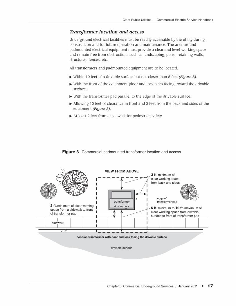
Transformer location and access
Underground electrical facilities must be readily accessible by the utility duringconstruction and for future operation and maintenance. The area around padmounted electrical equipment must provide a clear and level working spaceand remain free from obstructions such as landscaping, poles, retaining walls,structures, fences, etc.
All transformers and padmounted equipment are to be located:
� Within 10 feet of a drivable surface but not closer than 5 feet (Figure 3).
� With the front of the equipment (door and lock side) facing toward the drivablesurface.
� With the transformer pad parallel to the edge of the drivable surface.
� Allowing 10 feet of clearance in front and 3 feet from the back and sides of theequipment (Figure 3).
� At least 2 feet from a sidewalk for pedestrian safety.
Figure 3 Commercial padmounted transformer location and access
drivable surface
VIEW FROM ABOVE
curb
transformer
3 ft. minimum of clear working spacefrom back and sides
5 ft. minimum to 10 ft. maximum of clear working space from drivable surface to front of transformer pad
edge of transformer pad
position transformer with door and lock facing the drivable surface
2 ft. minimum of clear working space from a sidewalk to front of transformer pad
sidewalk
door and lock

Clark Public Utilities — Commercial Electric Service Handbook
18 � Chapter 3: Commercial Underground Services / January 2011
Transformer safety clearances
Clearances from padmounted transformers to structures are measured from the nearest metal portion of the transformer to the structure or any overhang. The clearance from a building is 10 feet if the building has combustible walls, and 3 feet if the building has non-combustible walls as shown in Figure 4. Table 4 provides additional safety clearances that apply to any oil-filled electricalequipment.
non-combustiblestructure and roof
combustiblestructure and roof
20 ft.
10 ft.
10 ft. minimum
operable windowor other opening
door or other opening
gas meter
transformer
transformer
transformer
hydrant
fuel dispensingfacilities
fireescape
10 ft.
10 ft.
10 ft.
10 ft.15 ft.
6 ft.
fuelstorage
3 ft.
min.
3 ft.
Figure 4 Commercial padmounted transformer minimum safety clearances

Clark Public Utilities — Commercial Electric Service Handbook
Chapter 3: Commercial Underground Services / January 2011 � 19
Feature Clearance distance
Combustible walls or roof (including stucco) 10 feet
Non-combustible walls (including brick, concrete, 3 feetsteel and stone), provided the side of the transformerfacing the wall does not have doors. Materials thatpass UBC standard 2-1 or ASTM E136-79 areconsidered to be non-combustible.
Fire sprinkler valves, standpipes and fire hydrants 6 feet
Doors, windows, vents, fire escapes, and other 10 feetbuilding openings
The water’s edge of a swimming pool or any body 25 feetof water
Facilities used to store hazardous liquids or gases 10 feet(e.g. service station fuel storage tank filler openingor emergency generator fueling points)
Facilities used to dispense or store hazardous 20 feetliquids or gases (e.g. service station gas pumps orpropane bulk dispensing tanks)
Gas service meter relief vents 15 feet
Table 4 Electrical equipment safety clearances
Guard post installation
The installation of guard posts (bollards) may be required when electrical equipment is exposed to vehicular traffic or minimum clearances around equipment cannot be met. It is the customer’s responsibility to supply, install and maintain guard posts when required by Clark Public Utilities personnel. See Figure 5.
Materials and installation requirements:
� 5-foot by 4-inch galvanized or steel pipe.
� Set each post 24 inches deep.
� Fill posts with concrete.
� Posts set in stable soil are to be surrounded by 6 inches of concrete.
� Unstable soil or sand requires 12 inches of concrete surrounding each post.
� If several guard posts are used, locate them no more than 5 feet apart or as otherwise specified by a Clark Public Utilities representative.

Clark Public Utilities — Commercial Electric Service Handbook
20 � Chapter 3: Commercial Underground Services / January 2011
� If the distance between the corner posts exceeds 5 feet, a removable center post is required (Figure 5).
� If a removable center post is installed, the threaded joint requires treatment with an anti-seizing agent.
� Paint exposed section of post “traffic yellow.”
Figure 5 Guard post (bollard) installation for commercial transformers
FRONT VIEW
VIEW FROM ABOVE
3 ft.minimum
18 in.minimum
on 45°
removable center post,as required
2 ft.
domed concrete
FINAL GRADE
4 in. galvanized/steel pipe,
concrete filled
4 in. galvanized/steel pipe,
concrete filled
concrete fill
removable center post,as required
coupling
do not fillcenter post
with concrete
edge of transformer pad
commercial transformer
door and lock
edge of transformer
NOTE: Additional guard posts may be required at back and sides of transformer.
Clark Public Utilities — Commercial Electric Service Handbook
Chapter 3: Commercial Underground Services / January 2011 � 21
Underground secondary junction box/pedestal
Site preparation and excavation
Prior to the installation of an underground secondary junction box/pedestal the job site requires:
� Staking of property lines.
� Excavation to final grade.
� Curbs poured.
A utility representative will determine the size of the junction box/pedestalrequired. Dimensions and equipment location will be indicated on the utility-provided electrical design.
The customer is then responsible for:
� Excavating the site to the dimensions provided by the utility representative.
� Installing the appropriate junction box/pedestal as called for in the electricaldesign.
� Installing appropriate labeling as called for on the utility-provided electricaldesign.
� Backfilling around the equipment to flush with final grade if in a hard surfacedarea or 2 inches below the junction box/pedestals’ indicated grade line if in alandscaped area.
Conduit and cable installation
Prior to Clark Public Utilities energizing a secondary junction box/pedestal the customer is responsible for:
� Installing conduit for all cables entering the enclosure.
� Installing conduits so that cable is pulled toward the bell ends.
� Providing, installing and marking all required futures.
� Capping all conduit futures that are plumbed into the enclosure.
� Requesting a standby with qualified utility personnel (two business days noticerequired) to plumb conduit and cable into any energized secondary enclosures.
Primary voltage installations to utility pole bases
A utility representative will install a pole bracket and clamp assembly at the base of the source pole. The commercial customer is responsible for providing and installing the following equipment up to Clark Public Utilities’ pole bases (See Figure 2 on page 14 of this chapter):
� 36-inch minimum depth (42-inch preferred) trench up to and exposing the pole base.
� Conduit and wire as outlined in the utility design.
Clark Public Utilities — Commercial Electric Service Handbook
22 � Chapter 3: Commercial Underground Services / January 2011
� Schedule 40 conduit elbow seated in the trench next to the pole base.
� Schedule 80 conduit extension installed in the pole bracket clamp attached to the pole base.
� Secondary junction box or pedestal as required by the utility design.
� Minimum 45-foot tail of wire coiled at the pole base (coil length varies based on pole height).
Additional pole base installation information:
� Do not trench to or install service to a utility pole that does not have a polebracket assembly installed. Contact the utility designer to install or reattach the assembly.
� Do not remove or relocate a utility-installed pole bracket assembly.
Clark Public Utilities — Commercial Electric Service Handbook
Chapter 4: Commercial Metering / January 2011 � 23
CHAPTER4Commercial Metering
This chapter contains information on the metering equipment required for connection of a new or upgraded commercial electric service. Call our Meter
department at (360) 992-8854 regarding questions about commercial electric service metering.
The following outlines the primary areas of interest in this chapter and providespage numbers for quick reference:
General commercial metering . . . . . . . . . . . . . . . . . . . . . . . . . . Pages 24 – 29
Useful information that relates to all commercial metering such as:
� Equipment location
� Access
� Equipment clearances
Self-contained metering systems. . . . . . . . . . . . . . . . . . . . . . . . Pages 29 – 31
Required in the following situations:
� Single-phase service, up to 400 amps (320 amps continuous)
� Three-phase service, up to 200 amps (120/208 or 120/240 Volt, 60 hp max)
� Three-phase service, 277/480 Volt, 125 hp maximum
Current transformer metering . . . . . . . . . . . . . . . . . . . . . . . . . . . Pages 31 – 34
Required in the following situations:
� Single-phase service exceeding 400 amps (320 amps continuous)
� Three-phase service exceeding 200 amps
� Services over 800 amps, require a switchboard
Multiple metered services . . . . . . . . . . . . . . . . . . . . . . . . . . . . . . . Pages 35 – 37
Outlining the requirements of:
� Commercial tenant spaces
� Residential multifamily
� Multiple meter labeling

Clark Public Utilities — Commercial Electric Service Handbook
24 � Chapter 4: Commercial Metering / January 2011
General commercial metering
The following information applies to all metering systems installed for Clark PublicUtilities’ commercial customers.
Responsibilities
Clark Public Utilities
The utility is responsible for furnishing, installing and maintaining the followingcommercial metering equipment:
� Self-contained and transformer-rated meters.
� Current transformers (CTs) and test switch.
� Potential (voltage) transformers (PTs).
� Associated low-voltage CT meter system wiring.
Only qualified and authorized Clark Public Utilities personnel shall unlock, remove,install and seal meters.
Commercial customer
The customer is responsible for providing, installing and maintaining the followingcommercial meter equipment:
� Meter base.
� Current transformer (CT) enclosure.
� Switchgear and cabinet.
� Connectors and insulating covers.
� Service conductors.
� Metering conduit between CT enclosure and meter base.
� Protection equipment.
� Equipment grounds.
Commercial meter bases
The following general requirements apply to all commercial meter bases called for by the utility and installed by the customer:
� Ring-type socket.
� Rated for exterior use and rain tight.
� Underwriters Laboratories (UL) rated.
� All unused openings in the enclosure are tightly sealed from the inside of the socket.
� Installed level, plumb and fastened securely to a rigid structure.
Clark Public Utilities — Commercial Electric Service Handbook
Chapter 4: Commercial Metering / January 2011 � 25
Grounding requirements
All meter equipment including bases, enclosures, switchgear and conduit shall bebonded and grounded in accordance with the NEC and the local governing office.
Service inspection and approval
The customer is responsible for securing the electrical wiring permit and request-ing an electrical inspection. Once the metering equipment is installed, the State of Washington, or city with jurisdiction, requires that the installation pass an electrical inspection prior to being energized by the utility. Clark Public Utilities will not connect a new or upgraded commercial electric service without notifica-tion of approval from the local governing office.
Additional customer equipment
Customer-owned load monitoring equipment and current-limiting fuses are notallowed inside a meter base, CT enclosure or distribution transformer. Clark PublicUtilities requires all customer-owned equipment to be installed on the load side of the meter system, inside the customer’s service panel or a separate enclosurebetween the meter base and panel.
Protection
A safety socket style self-contained meter base is required for all three-phase commercial services and any single-phase 480 volt service, 200 amps or less.Single-phase self-contained metering installed inside an approved meter enclosurealso requires a safety socket. Manual link bypass meter bases are acceptable forcommercial single-phase services less than 480 volts. See Meter socket types section on page 29 of this chapter for additional information on safety socket andmanual link bypass meter bases.
CT metered installations require a test switch provision mounted inside the meter base.
The ampacity rating of the main circuit breaker, or safety switch, cannot exceedthe maximum rating on the meter base. Three-phase services, with continuousampacity exceeding 200 amps, require CT metering.
All meter equipment is installed ahead of the main disconnect unless otherwiseagreed upon by Clark Public Utilities.
Meter equipment installed in areas accessible to vehicular traffic may require the installation of guard posts. The customer is responsible for providing, installing and maintaining these posts when required by a utility representative.See Guard post installation section and Figure 5 on pages 19 and 20 of this handbook for requirements.
Meter equipment location
Clark Public Utilities currently requires all meter bases and associated equipment(CT enclosures, switchgear, etc.) be attached to the outside of a permanent, fixed structure.

26 � Chapter 4: Commercial Metering / January 2011
Clark Public Utilities — Commercial Electric Service Handbook
Customer-owned commercial meter systems must be installed in a location thatallows 24-hour access to utility personnel for meter reading, testing and mainte-nance. This location is to remain free of obstruction, vibration, corrosives andabnormal temperature fluctuation. All meter equipment locations are subject toapproval by a Clark Public Utilities representative prior to installation.
Approved commercial meter equipment locations:
� Outside of the structure being served.
� On the ground floor, with the center of the meter 5 to 6 feet above finished grade (5 feet preferred).
� In an area that is not subject to being fenced-in or enclosed.
NOTE: Utility-provided lockboxes or hasp locks may be required to allow utilitypersonnel 24-hour access to metering equipment.
These locations allow Clark Public Utilities to:
� Read the meter in a cost-effective manner.
� Maintain the meter efficiently.
� Disconnect the service in case of emergency.
Do not locate meter equipment:
� On poles owned by Clark Public Utilities.
� On customer-owned poles or posts without prior utility approval.
� Where shrubs or landscaping could obstruct access.
� Above a stairway or window well.
� Inside a breezeway or fenced area.
� On a mobile structure such as a trailer.
� In a drive thru where vehicular traffic could obstruct access.
Metering installed in a vehicle traffic area will require guard posts. See guard postrequirements listed on pages 19 and 20 for additional information.
Electrical equipment rooms
Clark Public Utilities requires all commercial meter equipment to be mounted onthe outside of the structure containing the load being served. In certain situationsthe commercial structure may have an electrical equipment room. These installa-tions require prior approval from a utility representative before construction beginsand must provide 24-hour access to all meter equipment, without the need to callfor an appointment.
To maintain safety and allow maintenance of metering equipment, Clark PublicUtilities has the following requirements for electrical equipment rooms:
� Utility approval of the electrical equipment room design prior to construction.
� 24-hour access to all utility-maintained equipment.

Clark Public Utilities — Commercial Electric Service Handbook
Chapter 4: Commercial Metering / January 2011 � 27
� An access door that leads directly to the outside with the door opening outward.
� A minimum door size of 2 feet 8 inches by 6 feet 8 inches.
� Signage on the exterior of the door stating “Electrical Room.” The utility will alsoattach a small Clark Public Utilities identifying sticker.
� Well lit inside the room and the entrance.
� Contains electrical and communications equipment only, no storage of otheritems.
� Maintain proper working space and clearances around all metering equipment(Figures 6 and 7).
� A lockbox containing the access key, card key or door combination.
Lockbox requirements
Clark Public Utilities will provide and install the required lockbox for meter systems installed in an electrical equipment room. Lockboxes installed for access to electrical equipment rooms have the following requirements:
� Visible from and installed within 10 feet of the equipment room door.
� Key, card key or door combination provided by the customer to the Meter department, prior to any meters being set.
� Door combinations must be engraved on a hard plastic or metal tag no larger than 2 inches long by 1 inch in height, with a 1/16 inch hole punched in the top left corner for hanging.
� If equipment room door locks are changed, it is the customer’s responsibility to contact the utility as soon as possible to coordinate the exchange of new keys, card keys or combinations.
Clearance requirements for meter installations
Meter clearances are measured from the center of the meter socket or from the center of the face of the meter. The customer is required to provide and maintain these clearances at all times. The following clearances are required for all commercial meters:
� The center of the meter shall be between 5 and 6 feet above finished grade (5 feet preferred).
� A clear working space, 3 feet deep (Figure 6) in front of the meter, CT enclosureand switchgear. This space is to be kept clear of any obstructions including landscaping.
� There is a 10-inch minimum horizontal and vertical clearance between the center of the electric meter and any obstruction (Figure 6).
� If a recessed meter base is installed, a 10-inch radial clearance is required fromthe center of the meter to the closest portion of the wall (Figures 6 and 7).
� If a flush or recessed meter base is installed, the siding or finished surface of the structure shall not overlap the cover of the meter base.

28 � Chapter 4: Commercial Metering / January 2011
Clark Public Utilities — Commercial Electric Service Handbook
� The opening around a flush or recessed meter base must extend a minimum of 3 inches (Figure 7).
� Meters located near natural gas piping require a minimum of 3 feet of clearance.
Meter base installation tips
When installing a commercial meter base the following mechanical checks willensure the installation runs as smoothly as possible. After installing the meterbase, verify:
� Conductors are not under undue strain on the terminals.
� Terminals are rated for the size and type of conductor used.
� Strands have not been removed to make conductors fit under-sized terminals.
nearest side wall
or obstru
ction
3 ft.minimum
10 in.minimum
WORKINGSPACE
3 ft. minimumfrom meter faceor meter-related
enclosure
6 ft. maximum5 ft. preferred5 ft. minimum
10 in. minimum toany obstruction above
Figure 6 Meter equipment minimum work clearances

Clark Public Utilities — Commercial Electric Service Handbook
Chapter 4: Commercial Metering / January 2011 � 29
Figure 7 Recessed meter base detail
3 in. minimum
opening aroundmeter enclosure
METER HEIGHT:6 ft. maximum5 ft. preferred5 ft. minimum
FINAL GRADE
4 in. depth
Meter socket types
The table located on page 30 (Table 5) provides useful information on the requirements of the most common commercial meter sockets accepted by Clark Public Utilities.
Self-contained metering systems
Self-contained, or direct connect meters, carry full load current and connect directly across full line voltage. A safety socket or bypass meter socket is requiredfor all self-contained commercial meter systems.
Self-contained metering can be installed for the following services:
� Single-phase, up to 400 amps (320 amps continuous).
� Three-phase, up to 200 amps 120/208 or 120/240 volt with a maximum motor load of 60 hp.
� 277/480 volt services, up to 200 amps with a maximum motor load of 125 hp.
NOTE: Structures with loads greater than 320 amps of continuous current requireCT metering.

Clark Public Utilities — Commercial Electric Service Handbook
30 � Chapter 4: Commercial Metering / January 2011
THREE-PHASE
120/208 0–200 amp SC 127TB 7 No Yes No D4 wirewye Over 200 amp CT 121413 13 n/a n/a Yes CT rated
120/240 0–200 amp SC 127TB 7 No Yes No E4 wiredelta Over 200 amp CT 121413 13 n/a n/a Yes CT rated
277/480 0–200 amp SC 127TB 7 No Yes No D4 wirewye Over 200 amp CT 121413 13 n/a n/a Yes CT rated
neutral
load
line
neutralhi-leg(orange marking)
load
line
D E
Source Meter Reference B-Line # of Manual Safety Test Meter
Voltage Ampacity Base Part Number Terminals Block Socket Switch Configurationor Equivalent Bypass Required Diagram
SINGLE-PHASE
120 0–100 amp SC U121314 4 Yes No No A2 wire
0–200 amp SC U264 4 Yes No No B
120/240 201 to 320 SC 324N, 4 Yes No No B3 wire amp 324NF
Over 400 amp CT 12146 6 n/a n/a Yes CT rated
120/208 0–200 amp SC 5* Yes** No No C3 wire
(network) Over 200 amp CT 12148 8 n/a n/a Yes CT rated
Table 5 Commercial meter socket requirements
neutral
load
line lineneutral
load
line
neutral
load
A B C
Single-phase self-containedmeter socket configurations
Three-phase self-containedmeter socket configurations
SINGLE-PHASE
* 5th terminal is purchased from supplier separately
** House meters that are part of a residential meterpack do not require a manual bypass
SC = Self-contained CT = Current transformer B-Line part numbers are for cross reference only.
THREE-PHASE
U264,U121315 (<100 amp)
Clark Public Utilities — Commercial Electric Service Handbook
Chapter 4: Commercial Metering / January 2011 � 31
Safety socket
A safety socket allows the utility to maintain self-contained metering systems without interrupting service to the commercial customer. The meter terminals arede-energized allowing utility personnel to safely perform routine meter mainte-nance. A safety socket style meter base is required for the following services:
� All commercial three-phase services.
� Single-phase 240/480 volt services (municipal lighting only).
� Temporary commercial services that are three-phase or 480 volt.
� Single-phase services with metering installed inside a meter enclosure. Contact Clark Public Utilities’ Meter department for additional information on vandal-proof meter enclosures for commercial services.
NOTE: All 480 volt services, regardless of phase, require a safety socket.
Manual bypass
Manual bypass meter sockets also allow maintenance of self-contained meteringequipment while maintaining service to the customer. Meter terminals are not de-energized when bypassed. This style of meter base is acceptable for lower voltage (less than 480 volts), single-phase commercial services only. A manualbypass meter socket is required for:
� All single-phase commercial services 240 volts or less.
� 120/208 volt single-phase commercial network meters.
NOTE: Single-phase services with metering installed inside a meter enclosurerequire a safety socket.
The following commercial metering exceptions do not require a manual bypass or safety socket style meter base:
� Single-phase commercial temporary services (120/240 or 120/208 voltages).
� House meter sockets included in a factory-built multifamily residential meter pack.
Current transformer metering
Clark Public Utilities provides and installs the CTs, meter, test switch and associatedwiring. The customer provides and installs any additional metering equipmentbeyond the point of delivery. The location of CT metering equipment is subject to the approval of Clark Public Utilities. See Figure 8 for meter and enclosure clearances.
Current transformer (CT) metering is required in the following situations:
� Three-phase service exceeding 200 amps.
� Single-phase service exceeding 400 amps (320 amps continuous).
NOTE: Services over 800 amps also require a switchboard.
Clark Public Utilities — Commercial Electric Service Handbook
32 � Chapter 4: Commercial Metering / January 2011
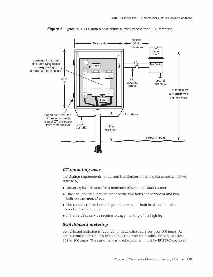
The CT metering equipment installed by the customer shall meet the followinggeneral requirements:
� Securely mounted, plumb and level on the outside of the structure.
� Rain tight and NEMA 3R-rated.
� 6 feet maximum height to top of cabinet or center of meter.
� Grounding and bonding of both the meter base and CT enclosure in accordancewith the NEC and local governing office.
In addition to the requirements previously listed the CT enclosure shall meet thefollowing:
� Bottom of cabinet a minimum of 18 inches from finished grade or floor.
� Side opening, hinged door with sealing provisions.
� Factory-installed hinges located on the opposite side of the enclosure fromwhere the meter socket is located.
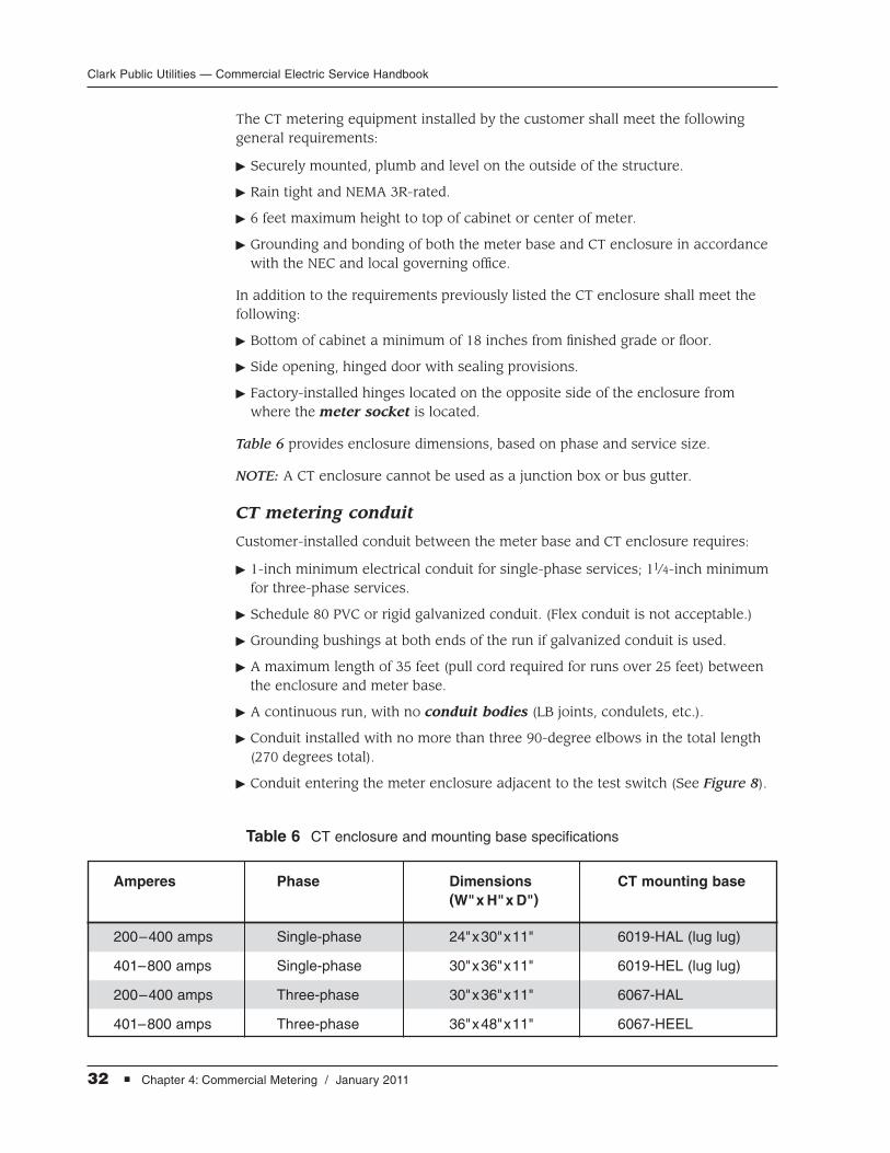
Table 6 provides enclosure dimensions, based on phase and service size.
NOTE: A CT enclosure cannot be used as a junction box or bus gutter.
CT metering conduit
Customer-installed conduit between the meter base and CT enclosure requires:
� 1-inch minimum electrical conduit for single-phase services; 11⁄4-inch minimumfor three-phase services.
� Schedule 80 PVC or rigid galvanized conduit. (Flex conduit is not acceptable.)
� Grounding bushings at both ends of the run if galvanized conduit is used.
� A maximum length of 35 feet (pull cord required for runs over 25 feet) betweenthe enclosure and meter base.
� A continuous run, with no conduit bodies (LB joints, condulets, etc.).
� Conduit installed with no more than three 90-degree elbows in the total length(270 degrees total).
� Conduit entering the meter enclosure adjacent to the test switch (See Figure 8).
Amperes Phase Dimensions CT mounting base(W"x H"x D")
200–400 amps Single-phase 24"x30"x11" 6019-HAL (lug lug)
401–800 amps Single-phase 30"x36"x11" 6019-HEL (lug lug)
200–400 amps Three-phase 30"x36"x11" 6067-HAL
401–800 amps Three-phase 36"x48"x11" 6067-HEEL
Table 6 CT enclosure and mounting base specifications
Clark Public Utilities — Commercial Electric Service Handbook
Chapter 4: Commercial Metering / January 2011 � 33
1 in. electrical conduit
FINAL GRADE
6 ft. maximum5 ft. preferred5 ft. minimum
30 in. wideconduit35 ft.
maximum
11 in. deep
36 in.tall
18 in. minimum
hinged door required,hinges on opposite
side of CT enclosurefrom meter socket
permanent load andline identifying labels
corresponding toappropriate connections
groundper NEC
groundper NEC
Load
Line
Test Switch
CT mounting base
Installation requirements for current transformer mounting bases are as follows(Figure 9):
� Mounting base is rated for a minimum of 50k amps fault current.
� Line and load side terminations require two bolts per connector and two bolts on the neutral bus.
� The customer furnishes all lugs and terminates both load and line side conductors to the bus.
� A 4-wire delta service requires orange marking of the high leg.
Switchboard metering
Switchboard metering is required for three-phase services over 800 amps. At the customer’s option, this type of metering may be installed for services sized 201 to 800 amps. The customer-installed equipment must be EUSERC-approved.
Figure 8 Typical 401–800 amp single-phase current transformer (CT) metering

Clark Public Utilities — Commercial Electric Service Handbook
34 � Chapter 4: Commercial Metering / January 2011
N
CT
7 in. minimum 7 in. minimum
two CT mounting bolts,6 places typical
bus marking “CT”typical 3 locations
10–32 machinescrew and washerdrilled and tapped
into bus
insulating support
insulating barrier
5 in. minimum
1-1/2 in.
7/8 in.
3/4 in.
1-3/8 in.
1-3/8 in.
1/4 in.
8-1/8 in.
3-5/16 in.
CTCT
All customer-installed switchboards require a:
� Current transformer (CT) mounting base.
� Service section.
� Set of bus bars/links.
� Panel(s).
� Meter base with provisions for a test switch.
� Means for locking the meter enclosure with independent 24-hour access to utility personnel.
� Concrete mounting pad.
� Case ground as required per the NEC.
NOTE: Customers requiring more than 480 volts of service will have primarymetering. Ownership and maintenance agreements for primary metered serviceswill be mutually agreed upon with Clark Public Utilities.
Figure 9 Commercial three-phase CT mounting base
NOTE: For additional information see EUSERC drawing 329B.
Chapter 4: Commercial Metering / January 2011 � 35
Clark Public Utilities — Commercial Electric Service Handbook
Multiple metered services
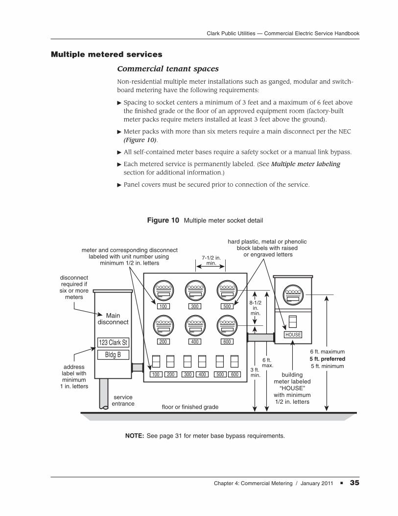
Commercial tenant spaces
Non-residential multiple meter installations such as ganged, modular and switch-board metering have the following requirements:
� Spacing to socket centers a minimum of 3 feet and a maximum of 6 feet abovethe finished grade or the floor of an approved equipment room (factory-builtmeter packs require meters installed at least 3 feet above the ground).
� Meter packs with more than six meters require a main disconnect per the NEC(Figure 10).
� All self-contained meter bases require a safety socket or a manual link bypass.
� Each metered service is permanently labeled. (See Multiple meter labeling section for additional information.)
� Panel covers must be secured prior to connection of the service.
Figure 10 Multiple meter socket detail
Maindisconnect
serviceentrance
disconnectrequired ifsix or more
meters
addresslabel withminimum
1 in. letters
floor or finished grade
3 ft. min.
6 ft. max.
8-1/2in.
min.
7-1/2 in.min.
6 ft. maximum5 ft. preferred5 ft. minimum
hard plastic, metal or phenolic block labels with raised
or engraved lettersmeter and corresponding disconnect
labeled with unit number using minimum 1/2 in. letters
buildingmeter labeled
“HOUSE”with minimum1/2 in. letters
Bldg B
123 Clark St
100
100
200
200 300 400 500 600
300
400
500
600HOUSE
NOTE: See page 31 for meter base bypass requirements.

36 � Chapter 4: Commercial Metering / January 2011
Clark Public Utilities — Commercial Electric Service Handbook
Residential multifamily
Multiple meter installations for residential services such as multifamily units orduplexes shall meet the following requirements prior to the utility connecting the service:
� Spacing to socket centers a minimum of 3 feet and a maximum of 6 feet abovethe finished grade or the floor of an approved equipment room (factory-builtmeter packs require meters installed at least 3 feet above the ground).
� Meter packs with more than six meters require a main disconnect per the NEC(Figure 10).
� Meter bases cannot be used as junction boxes.
� Three-phase house service meters, seated in a separate meter base require asafety socket.
� Stand-alone single-phase house meter services require a manual block bypasssocket.
� Each metered service is permanently labeled per Clark Public Utilities’ designrequirements. (See Multiple meter labeling section for additional information.)
� Panel covers must be secured prior to connection of the service.
Multiple meter labeling
Multiple meter installations require permanent labeling that identifies the unitand/or building address of the structure being served. The customer is responsiblefor ensuring that all meter bases, corresponding breakers, electrical panels, unitdoors and the building’s main disconnect are correctly labeled.
Label requirements
� Hard plastic, metal or phenolic block labels with raised or engraved letters are required. These types of labels are available at trophy and sign shops.NOTE: The use of label maker tape or permanent felt tip marker is not acceptable labeling.
� Meter equipment labels must correspond to permanent unit numbers attached to or next to corresponding unit doors.
� The main building (house) meter is labeled “HOUSE”.
� Each electrical panel requires a label displaying the number of the unit it serves. Electrical panel labels may be affixed to the outside or the inside of the hinged panel door.
� A minimum of 1/2-inch height letters are required for the labels of the meter,corresponding breaker, electrical panel, and building (house) meter.
� A minimum of 1-inch height letters are required for the building’s main disconnect label. If there are less than six meters and no main disconnect, the address/building number label may be attached to the meter pack.
� Multi-unit structures with less than six meters (duplex, triplex, etc.) also requirecorresponding labeling, as outlined above, at the meter, panel and unit door.
Chapter 4: Commercial Metering / January 2011 � 37
Clark Public Utilities — Commercial Electric Service Handbook
Building (house) meter service connect
Clark Public Utilities will not connect electrical service to the building (house)meter until permanent labeling has been completed at all required locations (meter base, corresponding breaker, electrical panel and main disconnect).
Individual unit meter service connect
Individual unit meters, their corresponding disconnect, electrical panel, and unitdoor require appropriate labeling at the time that meter is set. Proof of finaladdressing from the county or city with jurisdiction is required when permanentservice connection to an individual unit is requested.
NOTE: Labeling of residential multifamily meter bases may have additionalrequirements. Contact your utility representative for more information.

38 � Chapter 4: Commercial Metering / January 2011
Clark Public Utilities — Commercial Electric Service Handbook
This page left blank intentionally.

Clark Public Utilities — Commercial Electric Service Handbook
Appendix / January 2011 � 39
APPENDIX
Glossary
Approval — Acceptable to the authority having jurisdiction.
Associated equipment — As related to metering equipment: such as the currenttransforms, CT wiring and test switches.
Authority having jurisdiction — The qualified representative of a city, county orstate who has been authorized by governmental agencies to inspect.
Backfill — Native soil or soil brought in from another area, free from sharpobjects, rocks, scrap building material, and corrosive material.
Call Before You Dig number, 811 — National one call underground utility locating service.
Clark Public Utilities representative — The designated representative responsible for design and coordination of new or upgraded services to utility customers.
Clearance — A set distance between two objects.
Conduit — A listed or approved wireway with a smooth interior surface. Conduit may vary in size or schedule (wall thickness), depending on its usage, in accordance with codes and Clark Public Utilities’ specifications.
Conduit bodies — A combination of conduit and an electrical outlet. In the electrical industry may be referred to as a condulet or LB joint.
Current transformer (CT) — A device used to measure the current flow of services 200 amps or greater.
Current transformer (CT) mounting base — CT mounting base required for commercial CT metered services.
Directional drilling/boring — A trenchless method of installing undergroundelectrical conduit.

Clark Public Utilities — Commercial Electric Service Handbook
40 � Appendix / January 2011
Electrical equipment room — Locked room containing only electrical and communications equipment. Equipment rooms must provide 24-hour access to utility personnel without the need for an appointment.
Enclosure — A utility-approved lockable cabinet that contains meter equipmentand/or electrical connections.
Guard post — A bollard or post designed to protect the electrical facility or meterinstallation from vehicular traffic.
Joint use — A group of utilities that share space on a utility pole or trench.
Lockbox — Permanently installed, locked box containing keys, combinations orcard keys allowing utility personnel 24-hour access to metering equipment.
Manual bypass — A self-contained meter base socket with provisions for paralleling the meter circuit, allowing the meter to be removed without interrupting service to the commercial customer. Meter terminals are not de-energized when bypassed.
Meter pack — Ganged, modular and switchboard metering with multiple metersockets. Installed for commercial tenant spaces and residential multifamily units.
Meter socket — The mounting device consisting of meter jaws, connectors, andenclosure for accommodating socket-type meters.
Metering equipment — Any equipment associated with measuring electricalenergy.
Neutral — The grounded conductor in a single-phase, three-wire, or three-phase,four-wire system. The service conductor that is at zero potential to ground.
Phenolic block label — Permanent label attached to the meter base, corresponding breaker, electrical panel and door of the unit being served.
Point of delivery — The connection point of the meter base, on the customer’spremises, where Clark Public Utilities’ circuit and the customer’s system are interconnected.
Potential (voltage) transformer (PT) — A device used to reduce primary voltage to 120 volts. PTs are installed in conjunction with a CT rated meter.
Safety socket — A self-contained meter base socket with provisions to de-energize the meter terminals while maintaining service to the customer.
Secondary junction box/pedestal — Enclosure installed behind padmountedtransformers and at pole bases allowing multiple connections of underground secondary service.

Clark Public Utilities — Commercial Electric Service Handbook
Appendix / January 2011 � 41
Secondary service — The lower voltage, after transformation, used to supply the customer with electrical energy.
Self-contained — In reference to meter sockets: a device designed and rated tocontinuously carry the entire capacity of the service entrance equipment throughthe meter.
Source — Clark Public Utilities’ equipment (transformer, secondary junctionbox/pedestal, pole) that supplies the customer’s electric service.
Switchboard — Service entrance with secondary service conductors terminateddirectly to the customer’s main distribution center. A switchboard is required forservices 800 amps or greater.
Temporary service — An electrical service providing power to a customer on atemporary basis.
Transformer — Equipment used to reduce (step down) primary voltage to the secondary service required to supply the customer.
Underwriters Laboratories (UL) — A nationally recognized test laboratory thatlists materials it has tested and accepted.

Clark Public Utilities — Commercial Electric Service Handbook
42 � Appendix / January 2011
This page left blank intentionally.

Clark Public Utilities — Commercial Electric Service Handbook
Appendix / January 2011 � 43
Contact Clark Public Utilities’ Construction Services departmentat 360-992-8558, or return this completed worksheet to initiate a request for new or altered commercial electric service to:
PO Box 8900, Vancouver, WA 98668, or Fax to: 360-992-8823
Inquiry date:
Name of financially responsible party:
Mailing address:
Contact person:
Contact phone numbers: Business # Mobile # Fax #
Job site address: APN number:
Near address:
T Y P E O F S E R V I C E
Commercial service to: Number of tenant spaces:
Request for: � Permanent Service � Temporary Service � Information Only
New Service Size: Amps Existing service size and voltage:
Total connected load:
V O L T A G E R E Q U I R E M E N T S
SINGLE-PHASE THREE-PHASE
� 120/208 volt 3 wire � 120/208 volt 4 wire wye, grounded
� 120/240 volt 3 wire � 120/240 volt 4 wire delta
� 240/480 volt 3 wire � 277/480 volt 4 wire wye, grounded
Clark Public Utilities New or Altered Commercial Electric Service Worksheet
A utility designer will visit the job site and contact the customer for additional information.
Call the Construction Services department or consult our Commercial Electric Service Handbook for additional information.