Embed Size (px)
Citation preview

1 Commander 13.4.5
Commander 13.4.5
Overview .................................................................................................................................................................2 Prerequisites ...........................................................................................................................................................3 Download and Installation ......................................................................................................................................4 Quick Setup ............................................................................................................................................................5 Configuration ..........................................................................................................................................................6 S-Meter Display ................................................................................................................................................... 27 Transmission Meter Display ................................................................................................................................ 29 User-defined Controls .......................................................................................................................................... 32 Changing Frequency ........................................................................................................................................... 44 Changing Mode and Filter Setting ....................................................................................................................... 54 Changing Receiver Bandwidth ............................................................................................................................ 55 Using Memories ................................................................................................................................................... 57 Keying and Unkeying ........................................................................................................................................... 59 Controlling Multiple Radios .................................................................................................................................. 60 Network Service ................................................................................................................................................... 62 Monitoring Messages........................................................................................................................................... 64

2 Commander 13.4.5
Overview
Commander enables you to
• control your Elecraft, FlexRadio, Icom, Kenwood, TenTec, or Yaesu radio from your PC
• see DX Spots plotted on a zoom-able bandspread display of your radio's currently-active band
• see frequency-dependent control settings for devices like tuners and amplifiers
• store and recall frequencies (and associated modes) from 100 memories organized into 10 banks
• manually or automatically switch between up to four connected radios
• monitor messages between your radio and your PC
• provide DXKeeper, PropView, SpotCollector, and WinWarbler with access to your radio's frequency and mode

3 Commander 13.4.5
Prerequisites
To use Commander, you need
• a PC running Windows 95, Windows 98, Windows 98SE, Windows NT, Windows 2000, Windows XP, Windows 7, Windows 8, or Windows 10, ideally
o 133 MHz Pentium or better o 64 MB RAM or better
• an SVGA display or better
• a serial port connected to your radio via an appropriate radio interface
If you plan to run other members of the DXLab Suite in parallel with Commander, additional memory and a faster processor will be required for satisfactory performance; beyond 3 or 4 DXLab applications
Defects in Windows 95, Windows 98, and Windows 98SE precludes their use.
Windows 7, 8, and 10 require more RAM and CPU horsepower; consult Microsoft's prerequisites.

4 Commander 13.4.5
Download and Installation
Installing or Upgrading the DXLab Launcher The DXLab Launcher automates the installation of new DXLab applications, including Commander, and the upgrading of already-installed DXLab applications. If you're an aspiring DXLab user who has not installed any DXLab applications on your PC, or if you're a long-time DXLab user who has never installed the Launcher, then installing the Launcher will make it easy to install new DXLab applications and keep them up to date as upgrades are released. Step-by-step guides for installing the Launcher are available, both in HTML for browsing (http://www.dxlabsuite.com/dxlabwiki/InstallLauncher) and in PDF for printing (http://www.dxlabsuite.com/Download%20and%20Installation.pdf). You can uninstall Commander by running the Add/Remove Programs applet on the Windows control panel. If you have questions or suggestions, please post them on the DXLab reflector at http://groups.yahoo.com/group/dxlab. If you’re not a member, you can sign up at http://www.dxlabsuite.com/reflector.htm.

5 Commander 13.4.5
Quick Setup
Quick Setup instructions: controlling one radio
Step Directions
1 on the Configuration window's General tab
• select the radio's Model
• if you've selected an Icom or TenTec Omni, o indicate whether you'll be specifying the radio's CI-V Address in
decimal or hexadecimal radix (radio addresses given in Icom and TenTec manuals are in hexadecimal)
o enter the radio's CI-V Address in the specified radix o set the radio's CI-V Transceive parameter off (using its menu
system)
• if you've selected a TenTec Pegasus, specify the Control Folder containing your Pegasus control software; this folder should contain a file named PEGASUS.OUT
• if you've selected a Kachina, specify the Control Filename established by your Kachina software
2 in the Serial Port panel on Configuration window's Ports tab (skip if the radio Model is a TenTec Pegasus or FlexRadio SDR-1000)
• designate the serial port that is connected to your radio interface
• select the baud rate that matches your radio's settings
• if the radio requires that the RTS modem control signal be asserted, place this signal in the always on state; the Kenwood TS-2000, for example, has this requirement.
• if an external interface is being used and it derives its power from the serial port's DTR and/or RTS modem control signals, place these signals in the always on state
3 on the Configuration window's General tab, check the Continuous Frequency and Mode Interrogation box and set the interval to 200ms
• older radios like the Yaesu FT-767 require longer intervals, e.g. 400 ms
Note that checking the Continuous Frequency and Mode Interrogation checkbox with your Icom or TenTec Omni radio's CI-V Transceive parameter set on will degrade Commander's ability to track changes in your radio's frequency.

6 Commander 13.4.5
Configuration
Commander's Configuration window provides 10 tabs, each contains a related group of settings and controls that you can inspect and/or modify:
General • Radio panel o radio model and bus address
o polling and command execution interval o memory scan dwell time
o radio-specific options
• General panel o mousewheel disablement o Dual Receive enable/disable
o compute frequency-dependent device settings from transmit frequency when operating split
o display of User-defined Controls
o use of dual monitors
o diagnostic logging enable/disable
• transmit/receive switching
• VFO autorepeat rate
• Initial command
• Sub-band definitions
• Online help access
Ports • Primary CAT Serial Port panel o serial port parameters
o DTR and RTS behavior
• Secondary CAT Serial Port panel o serial port parameters
o DTR and RTS behavior o CAT Protocol, CI-V Address, and
Interrogation interval o Radio vs. Transceiver Control Application
• SO2R Serial Port panel o serial port parameters
o DTR and RTS behavior o SO2R protocol o Auxiliary Output frequency-dependent
device control
• Parallel Port panel o parallel port parameters
o radio selection and RX-TX switching
o data signal frequency-dependent device control
• Modem Command panel
Frequency-dependent Devices (3) • device name (appears as tab caption)
• control names
• control settings for each frequency
Filter Groups • Filter names and bandwidths
• Filter Group behavior when radio's mode changes
Memories • titles for each memory bank
• memory import and export controls
7 Commander 13.4.5
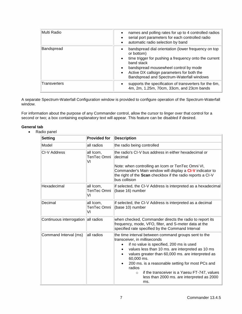
Multi Radio • names and polling rates for up to 4 controlled radios
• serial port parameters for each controlled radio
• automatic radio selection by band
Bandspread • bandspread dial orientation (lower frequency on top or bottom)
• time trigger for pushing a frequency onto the current band stack
• bandspread mousewheel control by mode
• Active DX callsign parameters for both the Bandspread and Spectrum-Waterfall windows
Transverters • supports the specification of transverters for the 6m, 4m, 2m, 1.25m, 70cm, 33cm, and 23cm bands
A separate Spectrum-Waterfall Configuration window is provided to configure operation of the Spectrum-Waterfall window. For information about the purpose of any Commander control, allow the cursor to linger over that control for a second or two; a box containing explanatory text will appear. This feature can be disabled if desired.
General tab
• Radio panel
Setting Provided for Description
Model all radios the radio being controlled
CI-V Address all Icom, TenTec Omni VI
the radio's CI-V bus address in either hexadecimal or decimal
Note: when controlling an Icom or TenTec Omni VI, Commander's Main window will display a CI-V indicator to the right of the Scan checkbox if the radio reports a CI-V bus collision
Hexadecimal all Icom, TenTec Omni VI
if selected, the CI-V Address is interpreted as a hexadecimal (base 16) number
Decimal all Icom, TenTec Omni VI
if selected, the CI-V Address is interpreted as a decimal (base 10) number
Continuous interrogation all radios when checked, Commander directs the radio to report its frequency, mode, VFO, filter, and S-meter data at the specified rate specified by the Command Interval
Command Interval (ms) all radios the time interval between command groups sent to the transceiver, in milliseconds
• if no value is specified, 200 ms is used
• values less than 10 ms. are interpreted as 10 ms
• values greater than 60,000 ms. are interpreted as 60,000 ms.
• 200 ms. is a reasonable setting for most PCs and radios
o if the transceiver is a Yaesu FT-747, values less than 2000 ms. are interpreted as 2000 ms.

8 Commander 13.4.5
o if the transceiver is a Yaesu FT-767, values less than 400 ms. are interpreted as 400 ms.
o with a fast Primary CAT port baud rate, recent radios like the IC-7800 can handle command intervals of 20 ms or lower, yielding smooth tuning but increasing Commander's use of your PC's CPU time
No interrogation while transmitting
all radios when checked, Commander will not ask the radio to report its frequency, mode, VFO, filter, and meter data while directing the radio to transmit; this option should not be enabled unless the transceiver cannot generate smooth CW while being asked to report this information
Verify CI-V command acceptance
all Icom, TenTec Omni VI
when checked, waits for a positive acknowledgement after transmitting each CI-V command and resends the command if either a negative acknowledgement or no acknowledgement is received; when enabled while controlling an Icom or TenTec Omni VI as the primary radio, the Messages window's Exec function is disabled
Sync transceiver frequencies before logging or spotting
all Icom, TenTec Omni VI
when checked, informs applications that log and spot that the active transceiver does not report changes in VFO B so they can direct Commander to refresh its VFO frequencies and disseminate them so that logged and spotted frequencies are accurate
Set transceiver UTC time on startup or selection
IC-7600, IC-7610, C-7700, IC-7800, IC-7850, IC-7851
when checked, sets the transceiver's UTC date and time from your PC's date and time when Commander starts or when the transceiver is selected
Emit subreceiver audio when dual receive enabled
IC-7800 when checked, directs the transceiver to emit subreceiver audio via backpanel connector ACC-A's AF signal when dual receive is enabled; when un-checked, the transceiver emits main receiver audio via this signal
Display outgoing CI-V commands in Message window
IC-7600, IC-7610, IC-7700, IC-7800, IC-7850, IC-7851
when checked, outgoing CI-V commands are displayed in the Message window (useful when connected to the radio via a USB cable)
Log Mode for Data-L or Data-U
transceivers for which Commander provides a Data-L or Data-U mode
specifies the "mode to be logged" conveyed to other applications, e.g. PSK31 or SSTV or FT8
If DXKeeper is installed, this selector is populated with the modes specified in DXKeeper's Modes.txt file if present, or its DefaultModes.txt file.
Log Mode for PKT or PKT-R
transceivers for which Commander provides a PKT or PKT-R mode
specifies the "mode to be logged" conveyed to other applications, e.g. PSK31 or SSTV or FT8
If DXKeeper is installed, this selector is populated with the modes specified in DXKeeper's Modes.txt file if present, or its DefaultModes.txt file.

9 Commander 13.4.5
Log Mode for DIGL or DIGU
Flex Signature 6000 Series
specifies the "mode to be logged" conveyed to other applications, e.g. PSK31 or SSTV or FT8
If DXKeeper is installed, this selector is populated with the modes specified in DXKeeper's Modes.txt file if present, or its DefaultModes.txt file.
Data sub-mode IC-7600, IC-7700, IC-7800, IC-7850, IC-7851
specifies which Data Sub-mode is selected when the mode is set to Data-L or Data-U
RTTY sub-mode K3, KX3 determines whether the radio's data mode is set to FSK D or AFSK A when its mode is set to RTTY or RTTY-R
Control Filename Kachina specify the Kachina control filename
Control Folder Pegasus specify the folder containing your TenTec Pegasus control software; this folder should contain a file named PEGASUS.OUT
provide A/B and TF-SET buttons
TS-480, TS-590, TS-590SG, TS-2000
when checked, Commander's Main window provides A/B and TF-S buttons instead of AxB and XFC buttons
provide a TF-SET button TS-990 when checked, Commander's Main window provides a TF-S button instead of an XFC button
Data transmission from ANI input
TS-480 when checked, the TS-480 is directed to transmit audio from the ANI signal in its backpanel ACC2 connector rather than from its front panel MIC input
Data transmission from USB interface or ANI input
TS-590, TS-590SG, TS-990
when checked, the transceiver is directed to transmit audio from its USB interface or from the ANI signal in its backpanel ACC2 connector rather than from its front panel MIC input
Assign subreceiver to VFO A when dual receive disabled
Orion when checked, the Orion's subreceiver is assigned to VFO A when dual receive is disabled; when unchecked, the subreceiver is unassigned
Radio's minimum VFO step is set to 10 hz
FT-1000D, MP-1000MKV, MP-1000, FT-990, FT-990_12, FT-900, or FT-890
when checked, operations that QSY the radio by 10 hz (e.g. wheeled mouse movements) will be accomplished by sending a "Step VFO" CAT command instead of the standard "QSY" CAT command, thereby avoiding any muting of receiver audio
This capability is disabled if the Secondary CAT Port is configured to Lead or Follow and Lead with the Interrogate selector not set to off.
Convey Decoded CW to WinWarbler
K3, KX3 when enabled with WinWarbler running, decoded CW is conveyed to WinWarbler
Convey Decode RTTY to WinWarbler
K3, KX3 when enabled with WinWarbler running, decoded RTTY is conveyed to WinWarbler
Monitor Connection Flex Signature 6000 Series
when enabled, Commander pings the radio once per second, enabling it to report a disconnection
Create VFO B at startup Flex Signature 6000 Series
when enabled, Commander will create VFO B (slice 1) on startup if it does not already exist
10 Commander 13.4.5
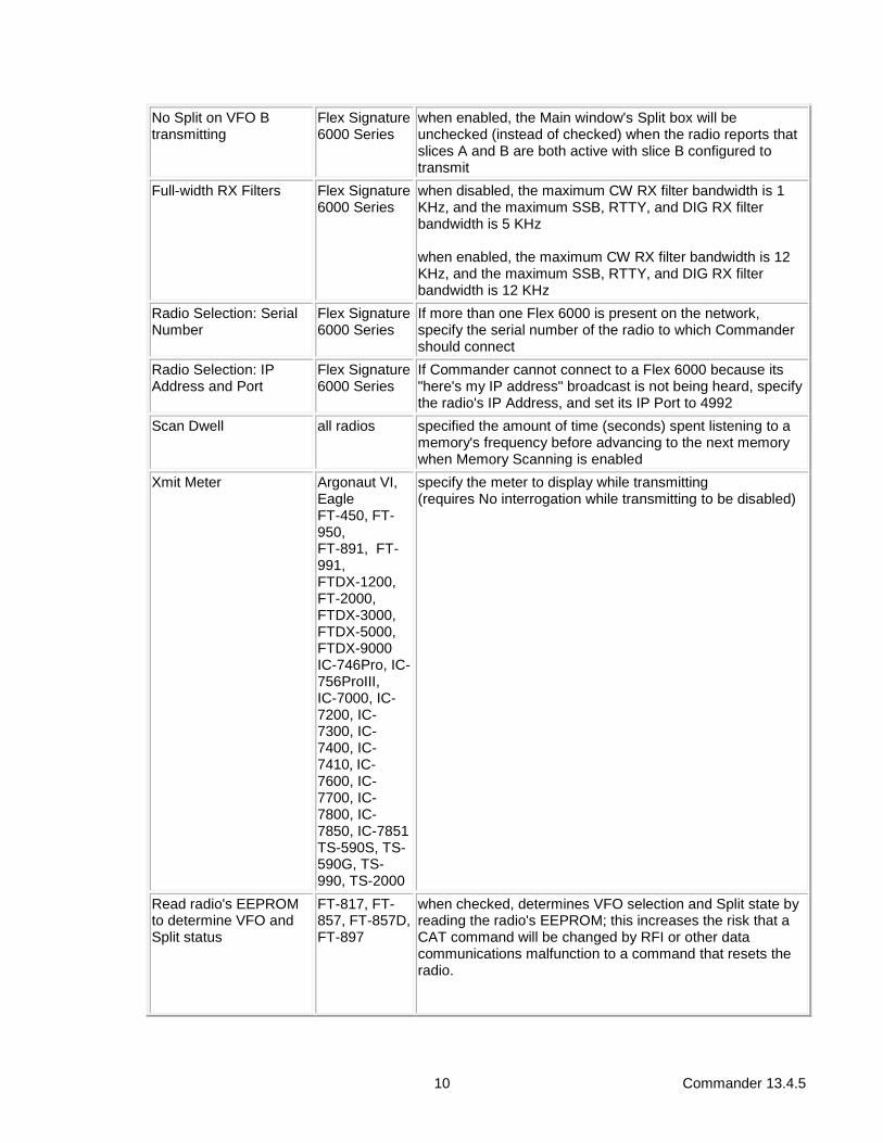
No Split on VFO B transmitting
Flex Signature 6000 Series
when enabled, the Main window's Split box will be unchecked (instead of checked) when the radio reports that slices A and B are both active with slice B configured to transmit
Full-width RX Filters Flex Signature 6000 Series
when disabled, the maximum CW RX filter bandwidth is 1 KHz, and the maximum SSB, RTTY, and DIG RX filter bandwidth is 5 KHz when enabled, the maximum CW RX filter bandwidth is 12 KHz, and the maximum SSB, RTTY, and DIG RX filter bandwidth is 12 KHz
Radio Selection: Serial Number
Flex Signature 6000 Series
If more than one Flex 6000 is present on the network, specify the serial number of the radio to which Commander should connect
Radio Selection: IP Address and Port
Flex Signature 6000 Series
If Commander cannot connect to a Flex 6000 because its "here's my IP address" broadcast is not being heard, specify the radio's IP Address, and set its IP Port to 4992
Scan Dwell all radios specified the amount of time (seconds) spent listening to a memory's frequency before advancing to the next memory when Memory Scanning is enabled
Xmit Meter Argonaut VI, Eagle FT-450, FT-950, FT-891, FT-991, FTDX-1200, FT-2000, FTDX-3000, FTDX-5000, FTDX-9000 IC-746Pro, IC-756ProIII, IC-7000, IC-7200, IC-7300, IC-7400, IC-7410, IC-7600, IC-7700, IC-7800, IC-7850, IC-7851 TS-590S, TS-590G, TS-990, TS-2000
specify the meter to display while transmitting
(requires No interrogation while transmitting to be disabled)
Read radio's EEPROM to determine VFO and Split status
FT-817, FT-857, FT-857D, FT-897
when checked, determines VFO selection and Split state by reading the radio's EEPROM; this increases the risk that a CAT command will be changed by RFI or other data communications malfunction to a command that resets the radio.

11 Commander 13.4.5
Reset all radios when clicked, resets communications with the transceiver
• can also be invoked by depressing the CTRL and SHIFT keys while clicking the Main window's Config button
Display Error Log all radios when clicked, displays Commander's Errorlog.txt file
Display License all radios when clicked, displays Commander's License
Set Time IC-7300, IC-7600, IC-7700, IC-7800, IC-7850, IC-7851
when clicked, updates the transceiver with the current UTC date and time
• for this function to work correctly, set the radio's UTC offset menu item to 0
• this button will be temporarily disabled for up to a minute after being clicked, or after startup or radio selection with the Set transceiver UTC time on startup or selection option enabled
Net Serv all radios when clicked, displays Commanders Network Service window, which governs communication with other applications via UDP and TCP
• General panel
Ignore Mousewheel when checked, directs Commander to not change transceiver frequency when you rotate your mousewheel
Accept 'Dual Rcv On' directives
when checked, allows other DXLab applications to enable the radio's Dual Receive (if available), e.g. when double-clicking on one of SpotCollector's Spot Database entries that specifies split frequency operation
Accept ' Dual Rcv Off' directives
when checked, allows other DXLab applications to disable the radio's Dual Receive (if available), e.g. when double-clicking on one of SpotCollector's Spot Database entries that specifies simplex operation
Use TX freq for devices when split
when checked, settings for frequency-dependent devices are computed from the transmit frequency when operating split
Switch to simplex on 1 MHz QSY
when checked, leave Split mode when the current VFO's frequency changes by 1 MHz or more
Use multiple monitors
when checked, windows that resided on a secondary monitor during the previous session will be restored to the same secondary monitor on startup; when not checked, all windows are restored to the primary monitor on startup
Log debugging Information
when checked, directs Commander to record diagnostic information in the file errorlog.txt located in Commander's folder
• PTT panel
Commander can switch the radio between receiving and transmitting by
• sending the radio an appropriate command via the serial port (if supported by the radio, and not suppressed)
• controlling an external interface via the serial port signals RTS and/or DTR
• controlling an external interface via parallel port pin 17
TX clicking this button directs the radio to switch from receiving to transmitting
RX clicking this button directs the radio to switch from transmitting to receiving
suppress CAT when checked, CAT commands will not be used to switch the transceiver between receiving and transmitting; presumably a hardware signal (serial port DTR, serial port RTS, or parallel port pin 17) will be exclusively used for this purpose, e.g. when an external sequencer is in use

12 Commander 13.4.5
• Frequency Colors panel
In clicking this button specifies the font color for in-band frequencies displayed in the Main window's primary VFO panel and all frequencies displayed in the secondary VFO and Memory Bank panels
Out click to specify the font color for out-of-band frequencies displayed in the Main window's primary VFO panel
Back click to specify the background color for frequencies displayed in the Main window
Def click to set the font colors for in-band frequencies and out-of-band frequencies and the background color for frequencies to the factory default values: cyan font for in-band frequencies, yellow font for out-of-band frequencies, and black background
• VFO Autorepeat Rate panel: determines the rate at which the Main window VFO's ▲, ▼, ◄, and ► buttons autorepeat when you click and hold them.
• Sub-band Definitions panel
Edit edits the sub-band definition file BandSegments.txt; if this file doesn't exist, creates it from DefaultBandSegments.txt
Reload reloads sub-band definitions from the file BandSegments.txt if it exists; otherwise, from the file DefaultBandSegments.txt
• You can define up to eight sub-bands for each amateur band from 160m to 23cm; when the primary VFO frequency does not lie within a defined sub-band, the frequency is displayed in the specified out-of-band color. By default, sub-bands are defined by the contents of the file DefaultBandSegments.txt in Commander's
folder. Each line in this file defines a sub-band by specifying a name, a lower-bound (in mHz), an upper-bound (in mHz), and a code (unused, set to 0).
• 160M, 1.800, 2.000, 0
80M, 3.500, 3.750, 0
75M, 3.750, 4.000, 0
40M, 7.000, 7.150, 0
40M, 7.150, 7.300, 0
60M, 5.330, 5.405, 0
30M, 10.100, 10.150, 0
20M, 14.000, 14.150, 0
20M, 14.150, 14.350, 0
17M, 18.068, 18.168, 0
15M, 21.000, 21.200, 0
15M, 21.200, 21.450, 0
12M, 24.890, 24.990, 0
10M, 28.000, 28.300, 0
10M, 28.300, 29.700, 0
6M, 50.000, 54.000, 0
4M, 70.000, 70.500, 0
2M, 144.000, 148.000, 0
1.25M, 222.000, 225.000, 0
70CM, 420.000, 450.000, 0
33CM, 902.000, 928.000, 0
23CM, 1240.000, 1300.000, 0

13 Commander 13.4.5
• To modify these sub-band definitions or define new sub-bands, click this panel's Edit button; this will create a file named BandSegments.txt initialize its contents from
the file DefaultBandSegments.txt, and open
BandSegments.txt for editing. If you hold a General
Class license in the United States, for example, you might define the following two sub-bands:
• 80M, 3.525, 3.750, 0
75M, 3.850, 4.000, 0
• Save your modifications, and click the panel's Reload button to put your new sub-band definitions into effect. When subsequently started, Commander will load sub-band definitions from BandSegments.txt .
• The following sub-bands are currently fixed, and cannot be modified by the user:
• 1.25M: 222.000 to 225.000
33CM: 902.000 to 928.000
23CM: 1240.000 to 1300.000
• User-defined Controls panel
Show within Main window
checking this box
• unchecks the Show by expanding Main window box, reducing Commander's Main window to its standard height
• disables all three Frequency-dependent device panels
• displays a User-defined Controls panel containing 8 buttons and 4 sliders that can be used to invoke and edit User-defined Controls
Show by expanding Main window
checking this box expands the height of the Main window to display a User-defined Controls panel containing 16 buttons and 8 sliders that can be used to invoke and edit User-defined Command Controls
• Initial Command panel: specifies a command to be executed when Commander starts, or when a new radio Model is selected
Command Function
a hexadecimal radio command specified by an even number of hexadecimal characters, e.g. FEFE26EO0700FD
all characters are sent to the radio via the primary CAT serial port, two per byte (useful for Icom, TenTec, and Yaesu radios
• substitution strings: slider value, CI-V address
an ASCII radio command specified by a sequence of ASCII characters preceded by a single apostrophe, e.g. 'AN1;
each character following the apostrophe is sent to the radio via the primary CAT serial port (useful for Kenwood and Elecraft radios)
• substitution strings: slider value, ASCII character
a sequence of ascii characters preceded by a single tilde, e.g. ~slice set 0 rxant=ant1
ASCII radio command -- each character following the tilde will be sent to your radio via the TCP/IP connection (useful for Flex Signature radios)
• substitution strings: slider value, ascii character
• Initial Command Sequence panel
Enable when enabled, specifies a Command Sequence to be executed when Commander starts, or when a new radio Model is selected
• If an Initial Command is also specified, the Initial Command Sequence is executed after the Initial Command
Edit when clicked, displays a window that lets you define, edit, and test the initial

14 Commander 13.4.5
command sequence
• Guidance panel
Browser pathname if this setting is blank, Commander displays online help using your PC's default HTML browser; if this setting contains the pathname of an HTML browser, Commander displays online help using that browser.
Select button displays a file selector dialog that allows you to choose a Browser pathname
show control explanations
when checked, enables the display of explanatory information when the mouse cursor lingers over a textbox, button, checkbox, display pane, or setting.
Help button displays the information you are now reading
A separate Spectrum-Waterfall Configuration window is provided for controlling the Spectrum-Waterfall window.
Ports tab
• Primary CAT Serial Port panel o Port# selector: specifies the PC serial port to which the radio is connected o Baud Rate selector: specifies the baud rate that the radio is using (hardwired in some radios,
menu-configurable in others; consult the radio's manual) o Parity selector: specifies whether the parity is enabled (hardwired in some radios, menu-
configurable in others; consult the radio's manual) o Word Length selector: specifies the number of data bits that the radio is using (hardwired in
some radios, menu-configurable in others; consult the radio's manual) o Stop Bits selector: specifies the number of stop bits that the radio is using (hardwired in some
radios, menu-configurable in others; consult the radio's manual) o DTR selector: specifies the behavior of the Data Terminal Ready modem control signal of the
selected port
Off DTR is never asserted
On DTR is always asserted (required if an external interface that derives its power from DTR is in use)
TX DTR is asserted when Commander is directed by another application to transmit, or when TX is clicked until RX is clicked
o RTS selector: specifies the behavior of the Request To Send modem control signal of the selected port
Off RTS is never asserted
On RTS is always asserted (required if an external interface that derives its power from RTS is in use)
TX RTS is asserted when Commander is directed by a client application to key the radio, or when the PTT On button is clicked until the PTT Off button is clicked
Flow RTS is asserted when Commander has data to send to the radio via the serial port; this data will not be sent until the radio responds by asserting the incoming modem control signal Clear To Send (CTS)

15 Commander 13.4.5
• Secondary CAT Serial Port panel o Enable: when checked, Commander will control the radio, device, or application attached to the
Secondary CAT Port as specified by the Behavior options and using the specified CAT protocol o Behavior options
▪ Follow Primary: when selected, Commander will direct the radio, device, or application connected to the secondary port to track changes in the primary radio's frequency and mode, and provides the Update every second option
▪ Lead Primary: when selected, Commander and the primary radio will track the frequency and mode of the radio, device, or application connected to the Secondary CAT Port
▪ Follow & Lead Primary: when selected, Commander, the primary radio and the radio, device, or application connected to the Secondary CAT Port will track each other's frequency and mode
▪ Update every second: when checked, Commander will update the radio, device, or application connected to the Secondary CAT Port to track primary radio's frequency and mode once each second; enabling this option will convey the primary radio's frequency and mode to a radio, device, or application connected to the Secondary CAT Port that is powered up or started after Commander is already running
▪ Follow Alternate VFO when Split: when checked and Commander's Split box is checked, the radio, device, or application connected to the secondary port will follow the primary transceiver's alternate VFO
▪ Follow & Lead Alternate VFO when Split: when checked and Commander's Split box is checked, the radio, device, or application connected to the secondary port will follow the primary transceiver's alternate VFO, and the primary radio's alternate VFO will track frequency changes from the radio, device, or application connected to the secondary port
o CAT protocol selector: specifies the CAT protocol to be used for interaction with
BobCAT the BobCAT SDR Console using the ICOM CI-V protocol via a connected virtual serial port pair
CW Skimmer CW Skimmer using the Kenwood protocol via a connected virtual serial port pair
Elecraft an Elecraft K3
FlexRadio a FlexRadio SDR via a connected virtual serial port pair
ICOM an Icom transceiver
Kenwood a Kenwood transceiver
Omni VI an TenTec Omni VI transceiver
Perseus a Microtelecom Perseus ▪ via a connected virtual serial port pair to the virtual serial port created by
the radio's USB interface ▪ communications employs the Icom CI-V protocol ▪ CI-V commands will be sent to mute and un-mute the Perseus' audio
when the primary transceiver switches from RX to TX and from TX to RX respectively
PW1 an Icom IC-PW1 amplifier (Commander will send alternating frequency and mode updates every 2.5 seconds to prevent CI-V bus collisions) Note: Commander will display a PW1 alert indicator above the CAT Protocol selector when a CI-V message is received from the PW1, and will display a PW1 indicator to the left of the Main window's Help button. This is normal when powering up a connected Icom transceiver or when powering up the PW1, and should be reset by clicking either indicator. If either PW1 indicator appears after power-up, CI-V bus collisions could be compromising frequency tracking; do not operate the PW1 with automatic frequency tracking until this situation is corrected!

16 Commander 13.4.5
SteppIR a SteppIR antenna controller using Icom CI-V instructions (sends frequency updates every 2.5 seconds)
o CI-V-Addr box: if the CAT protocol is Icom or PW1 or SteppIR, specifies the CI-V Address in
hexadecimal o Interrogate selector: if the CAT protocol is Icom, determines whether and at what rate to request
frequency and mode reports. o Port# selector: specifies the PC serial port; if the specified port is assigned to an enabled
transceiver on the Configuration window's MultiRadio tab, that transceiver's Main window selection button will be disabled ("grayed out")
o Baud Rate selector: specifies the baud rate o Parity selector: specifies whether parity checking is enabled o Word Length selector: specifies the number of data bits o Stop Bits selector: specifies the number of stop bits o DTR selector: specifies the behavior of the Data Terminal Ready modem control signal
Off DTR is never asserted
On DTR is always asserted (required if an external interface that derives its power from DTR is in use)
o RTS selector: specifies the behavior of the Request To Send modem control signal
Off RTS is never asserted
On RTS is always asserted (required if an external interface that derives its power from RTS is in use)
Flow RTS is asserted when Commander has data to send via this serial port; the data will not be sent until the connected device responds by asserting the incoming modem control signal Clear To Send (CTS)
• SO2R Serial Port panel o SO2R protocol selector: specifies the SO2R protocol to be used (microHam or OTRSP) o Enable: select to send commands to an attached SO2R device using the specified protocol to
convey radio selection changes, band changes (OTRSP protocol only), and ACC/Auxiliary Output changes as a function of the current transceiver's frequency; no commands will be sent unless multi-radio support is enabled and a radio is selected.
o ACC/Auxiliary Outputs panel: displays the last ACC/Auxiliary Output command sent to the SO2R device
Enable when checked, the integer value of the selected Device Control is placed onto the specified ACC or Auxiliary outputs
Device specifies the frequency-dependent device whose Control value is placed onto the specified ACC or Auxiliary outputs
Control specifies the frequency-dependent device's Control whose value is placed onto the specified ACC or Auxiliary outputs
▪ note: if the SO2R protocol selector is set to microHam, the selected frequency-dependent device's Control must specify the band with two digits, e.g. 01 for 160m, or 11 for 6 meters.
• Port# selector: specifies the PC serial port
• Baud Rate selector: specifies the baud rate
• Parity selector: specifies whether parity checking is enabled
• Word Length selector: specifies the number of data bits
• Stop Bits selector: specifies the number of stop bits

17 Commander 13.4.5
• DTR selector: specifies the behavior of the Data Terminal Ready modem control signal
Off DTR is never asserted
On DTR is always asserted (required if an external interface that derives its power from DTR is in use)
• RTS selector: specifies the behavior of the Request To Send modem control signal
Off RTS is never asserted
On RTS is always asserted (required if an external interface that derives its power from RTS is in use)
Flow RTS is asserted when Commander has data to send via this serial port; the data will not be sent until the connected device responds by asserting the incoming modem control signal Clear To Send (CTS)
• Parallel Port panel o Enable Radio & PTT: if this box is checked, Commander encodes the currently-selected radio on
pins 16 and 14 of the specified parallel Port Address, and asserts pin 17 when Commander is directing the transceiver to transmit.
Radio Parallel port pin 16
Parallel port pin 14
1 0 0
2 0 1
3 1 0
4 1 1
o Port selector: chooses one of four standard parallel port addresses o Port Address: selects a parallel port o Data Signals panel: if the Enable box is checked, Commander places the integer value
of the selected Device Control onto data bits 7 (most significant bit, pin 9) though 0 (least significant bit, pin 2) of the specified parallel port
Enable when checked, the integer value of the selected Device Control is placed onto the specified parallel port's data bits
Device specifies the frequency-dependent device whose Control value is placed onto the specified parallel port's data bits
Control specifies the frequency-dependent device's Control whose value is placed onto the specified parallel port's data bits
• Modem Command panel
Command if Commander is controlling a remote transceiver via a serial port connected to a modem, use this textbox to specify the modem initialization and dialing commands to be sent when the Send button is activated; if a command is specified, Continuous Frequency and Mode Interrogation is disabled on startup
Send button when clicked, sends the Command to the modem via the serial port
Frequency-dependent Device tabs Devices like antenna tuners and linear amplifiers have controls whose settings are frequency-dependent. While high-end units do this automatically, most require the operator to manually set the controls whenever the operating frequency changes. Commander enables you to specify tables for such devices; it then performs a table lookup based on the transceiver's current frequency and displays the correct settings, eliminating the need for paper tables taped to the front-panel. Up to four different frequency-dependent devices are supported, each with up to three controls.

18 Commander 13.4.5
• You can optionally place the settings from one control of one device onto a parallel port's data bits; this permits the direct control of external devices like antenna switches.
• You can optionally use a control's settings to set the value of one a command-generating slider; this could be used, for example, to automatically control your transceiver's power output as a function of frequency
The right side of Commander's Main window is shared by frequency-dependent device readouts, receiver filter controls, and eight banks of ten memories. If the frequently-dependent device panels are not visible, clicking the Main window's Filters & Devices button will make them and the receiver filter controls appear in place of the memory banks.
Initially, Commander refers to the four frequency-dependent devices as Device 0, Device 1, Device 2, and
Device 3; as part of the setup procedure, you can replace these generic names with more meaningful names like
Amplifier, or Tuner.
To setup a frequency-dependent device, use the following procedure:
Step Directions
1 on Commander's Main window, click the Config button
2 on Commander's Main window, click the Filters & Devices button if its visible
3 on Commander's Configuration window, select the Device 0 tab (you can use the Device 1, Device 2, and Device 3 tabs to setup a second, third, and fourth frequency-dependent device, if desired)
4 check the Device 0 tab's Enabled box; in the Main window, you'll see a Device 0 panel appear (the contents of this panel will be updated as you complete this procedure)
5 enter the name of the device in the Device Name box; the name of the tab will change from Device 0 to the name you specify
6 enter the number of controls associated with this device in the # Controls box; accepted values are 1, 2, or 3.
7 enter the name of the first control in the Control 1 box; if there's a second control, enter its name in the Control 2 box and if there's a third control, enter its name in the Control 3 box.
• to drive a command-generating slider with a control, set the control's name to <Sn> where n
is a number from 1 to 8 that identifies the slider being driven
8 scroll the Device Table to the frequencies of interest, and enter the control values for each such frequency; after entering each value, strike the Enter key
• to modify an existing device table entry, select the information you wish to change by clicking it with the left mouse button, and then type in the new information
• to add a new entry to a device table, scroll to its bottom, where you will find a blank line with an asterisk in the grey left-most column. Key in the entry's frequency, and then strike the Enter key. Commander automatically sorts the Device Table in ascending frequency order, so the new entry may disappear from view. If you're planning to add several entries, it is more efficient to first create the entries, and then scroll through the Device Table entering control values for the newly-created entries.
• to delete an entry in the device table, select it by clicking in the grey left-most column; then strike the Delete key.
• it is not necessary to enter control values for every frequency in the table
• depressing the CTRL key while clicking on a Device Table entry will QSY your transceiver to that entry's frequency, making it easy to determine or verify settings
9 enter a percentage in the Tolerance box (2% is a reasonable default)
• the percentage difference between the frequency of the Device Table entry closest to your radio's current frequency and your radio's current frequency must be less than or equal to the specified Tolerance for that entry's control settings to be displayed
• if there is no Device Table entry within the specified Tolerance, the Device's control settings will be blanked

19 Commander 13.4.5
10 click the Save button and specify a destination filename into which the Device data just specified will be saved for use in subsequent Commander sessions.
. If Commander is terminated and later restarted, saved device data will automatically be reloaded for each Device that was enabled when Commander was terminated.
You can use the above procedure to record data for an alternate device -- e.g. a backup amplifier -- in a separate file. The Select button allows you to choose the file from which the Device data will be loaded. The ReLoad button restores the Device data to the values contained in the most recently-loaded file.
You can specify the colors used to display a Device's settings on the right side of Commander's Main window via buttons in the Setting Readout Colors panel:
• Font - click this button specify the font color for this device's settings displayed in the Main window
• Background - click to specify the background color for this device's settings displayed in the Main window
• Default - click to use "factory default" colors for this device's settings displayed in the Main window: cyan font, and black background
You can select one control of one frequency-dependent device whose integer value will be placed on data bits 7 through 0 of a specified parallel port. This can be used to control an antenna switch, for example. Filter Groups tab A Filter Group is a named configuration of one or more receiver bandwidth settings. If Filter Groups are supported for a particular radio Model, Commander remembers the Filter Group last used in each mode. Checking the restore Filter Group on mode change box directs Commander to automatically restore the last used Filter Group whenever a new mode is selected.
If the radio Model is an Icom, the Filter Groups tab displays the Icom Filter Group Names panel, which lets you assign names to the each Filter Group. Early Icom transceivers provides two Filter Groups whose functions are hardwired: group 1 provides a wide bandwidth filter, and group 2 provides a narrow bandwidth filter. Later Icom transceivers allow the user to reconfigure one or both filter groups for different bandwidth (by physical replacement or in high-end transceivers via menu selection), and some include a third group ambiguously referred to as normal. The Icom Filter Group Names panel lets you assign names to each group that are meaningful given the actual filter configuration of your transceiver; these names appear in the Group selector in the Main window's Filters panel, enabling you to change bandwidth with a mouse click.
If the radio Model is set to MP1000 or MP1000MKV, the Filter Groups tab displays the Yaesu FT1000MP and
Mark V panel which contains a table, each of whose rows is comprised of cells that define a Filter Group; a Data File panel is also display, enabling you to specify the file into which Filter Groups are saved.
• To modify an existing Filter Group's Mode, 2nd IF, 3rd IF, or Sub cell, click in the cell to display a down-pointing triangle; then on this triangle to display a list of alternatives from which you can choose with a mouse click. After you change any cell, a pencil icon appears in the row's left-most column:
o to undo the change, strike the ESC key o to record the change, click on any other row in the table, or strike the UpArrow or DownArrow
keys.
• To delete a Filter Group, click in its row's left-most column, and then strike the Delete key.

20 Commander 13.4.5
• To add a new Filter Group, 1. click on any cell in the bottom-most table entry, which is marked with an asterisk in its left-most column; doing so will create an empty new row, whose cells you can then populate 2. if you haven't specified a Filename in the Data File panel, select one by clicking the Data File panel's Select button 3. click the Data File panel's Save button to save all Filter Groups to the specified Filename; Filter Groups saved in this way will automatically be loaded from the specified Filename when Commander is started
If the radio Model is set to Orion or Eagle, the Filter Groups tab displays a Default Bandwidth by
mode panel that provides the option to set the default bandwidth to a specified value when the transceiver's mode changes.
Memories tab Textboxes in this tab's Memory panel allow you to establish a title for each memory bank; this title serves as the caption for the Main window panel that displays the currently-selected memory bank.
• When checked, the Disable Save Buttons box disables (grays out) the Save buttons in the Main window's Memory Bank panel; clicking the word Save in the Main window's Memory Bank panel will display the Config window's Memories tab
• The Export Memories button saves the information associated with all memories that contain at least a frequency and mode to a specified file.
• The Import Memories button loads memories from information contained in a specified file. Any errors are placed in an error file that's displayed after the operation completes.
• The Clear Memories button erases the contents of all memories.in the current memory bank
• The User-defined Sequence after Memory Select option lets you specify the name of a User-defined Command Sequence to automatically be executed when a Memory Bank panel's Sel button is clicked after a Delay specified in milliseconds (up to a maximum of 10,000). If no name is specified, no sequence will be executed; if no delay is specified, the named sequence will be executed immediately.
Multi Radio tab Using the controls on this tab, you can configure Commander to support rapid switching among up to four radios. Switching can be manual, via a set of buttons on the VFO panel on Commander's Main window, or automatic as a function of amateur band.
Controls on this tab's Control panel let you specify a transceiver model, a CI-V Address (for Icom and TenTec radios), the need for continuous frequency and mode interrogation, and the interval (in milliseconds) between command groups for up to four radios; these controls are identical in function to the controls on the General tab. You can specify a unique name for each radio, which is used to identify the radio for both manual and automatic switching; if you have a pair of Icom 756 Pro radios, for example, with one dedicated to HF operation and the other to VHF operation, you might name the first HF 756Pro and the second VHF 756Pro. The Enable boxes in this panel let you designate which radios are active. If you are switching between radios 1 and 2, enable them both, and uncheck the enable boxes associated with radios 3 and 4.
• If the Model selector is set to Kachina, clicking the provided Select button enables you to choose a Control Filename for the radio
• If the Model selector is set to Pegasus, clicking the provided Select button enables you to choose a Control Folder for the radio
• If the Model selector is set to SDR-6300, SDR-6500, or SDR-6700, o clicking the provided Select button enables you to specify the radio's Serial Number, or its IP
Address and IP Port o the Interrogate checkbox controls the Monitor Connection setting

21 Commander 13.4.5
Controls on the Serial port panel let you specify serial communication port settings for each of four radios. These controls are identical in function to those on the Ports tab's Primary CAT Serial Port panel. If you are controlling multiple Icom or TenTec radios on the same CI-V bus, assign identical serial port parameters to these radios. Due to space compression, the Serial Port control uses a hyphen to mean "none", and the Parity, DTR, and RTS controls use single letter abbreviations:
Parity Abbreviation Meaning
N No parity
O Odd parity
E Even parity
M Mark parity
S Space parity
DTR and RTS Abbreviation Meaning
N Always off
Y Always on while this radio is selected
X On to transmit
F Flow control (RTS only)
Note that each transceiver's Enable box will remain disabled (grayed out) until all of its items have been selected. If your transceiver doesn't need DTR or RTS, for example, set those selectors to N rather than leave the blank.
If the port assigned to an enabled transceiver is currently specified as the Secondary CAT Serial Port panel, the transceiver's Main window selection button will be disabled ("grayed out").
Clicking a radio's Update button will update that radio's Multi Radio serial port settings from the settings specified on the Ports tab's Primary CAT Serial Port panel. Thus once you have the settings on the Primary CAT Serial Port panel properly configured to enable Commander to control a transceiver, you can "transfer" those settings to the Multi Radio tab's CAT Serial Port panel by clicking the appropriate Update button.
A User-defined Control Set specifies
• an Initial Command to be executed when Commander starts, or when a new radio model is selected
• the pathname of a file that specifies an Initial Command Sequence to be executed when Commander starts, or when a new radio mode is selected (after executing the initial CAT command, if one is specified)
• the pathnames of up to 32 files, each specifying a Command Sequence
• the pathnames of up to 16 files, each specifying a Command-generating Slider The 32 Sequence pathnames and 16 Slider pathnames are organized into two banks, each specifying two rows of 8 Sequence pathnames and 4 slider pathnames; use the Second row and Alt bank checkboxes to select the bank and row whose pathnames you wish to view or modify.
To create or display a radio's Control Set, click the radio's Edit button in this tab's User-defined Controls Sets panel. If a Control Set for this radio has been defined, this
• loads the 32 Command Sequences from the pathnames specified in the Control Set
• loads the 16 Sliders from the pathnames specified in the Control Set Selecting a radio for which a Control Set is specified
• directs the transceiver to execute the CAT command specified in the Control Set's Initial Command
• directs the transceiver to execute the Control Set's Initial Command Sequence
• loads the 32 Command Sequences from the pathnames specified in the Control Set
• loads the 16 Sliders from the pathnames specified in the Control Set

22 Commander 13.4.5
By default, switching between radios is manual, effected by clicking the radio selection buttons on the Main window's VFO panel. To enable automatic radio switching, use the Selection by band panel to choose a radio for each amateur band, and then check the Auto box.
You can configure Commander to identify the currently-selected radio via a binary encoding on pins 16 and 14 of a specified parallel port.
Bandspread tab The controls on this tab influence the behavior of the Bandspread window's slide rule dial, its Band Stack, and its presentation of DX Spots.
The always on top box, when checked, ensures that the Bandspread window will not be obscured by any other application window except one similarly configured.
If the color-code frequency pointer box is checked, the current frequency indicator on the Bandspread window's slide rule dial will be rendered in the specified in-band color if the transceiver's frequency is in-band, or in the specified out-of-band color if the transceiver's frequency is out-of-band. If the box is unchecked, the current frequency indicator will be rendered in red, independent of transceiver frequency.
The Spectrum-Waterfall window box is enabled if Commander is controlling an Icom IC-7300, IC-7610, IC-7850, or IC-7800, and if the Primary CAT Port baud rate is set to 115,200. Checking this box will display Commander's Spectrum-Waterfall window, which horizontally displays realtime spectrum data, a waterfall, and the callsigns of active DX stations. Note that Icom radios will only report spectrum data if they are directly connected to a computer via USB.
The Orientation panel determines whether the slide rule dial shows lower frequencies at its top and higher frequencies at its bottom, or higher frequencies at its top and lower frequencies at its bottom.
The Band Stack panel's dwell time setting specifies the interval that determines how long the radio must pause on a frequency before that frequency and the radio's current mode are saved onto the current Band Stack; the dwell time is specified in seconds.
The Mousewheel Motion panel determines the increment by which your radio is QSYed when the Bandspread window is active and you rotate your mouse's wheel by one click. Increments are specified by mode, and expressed as a percentage of the slide rule dial's frequency range; negative percentages can be used to reverse the meaning of mouse wheel rotation to suit the user's taste. Fractional values like 0.05 can be specified for very
slow tuning rates. The mode-specific settings make it convenient to setup a faster tuning rate for SSB operation than for CW or RTTY operation.
In the DX Spot Font panel,
• the Name sub-panel lets you specify a large font to be used to render DX spots on the Bandspread window's slide rule dial when the font size is 8 or greater, and a small font to be used when the font size is less than 8; this allows the use of fonts design to be readable at small point sizes, e.g. Small Fonts
• The Size sub-panel specifies the font size with which DX spots are to be rendered on the Bandspread window's slide rule dial; font sizes can be specified independently for each dial range.
DX Spot settings govern the handling of active DX callsigns in the Bandspread window and in the Spectrum-Waterfall window's DX Callsign Section:
• if hide duplicates is checked, only a station's most recent spot in each mode will be displayed on the Bandspread window's slide rule dial and the Spectrum-Waterfall window's DX Callsign Section ; if not checked, every spot will be displayed.
• if Request prop forecast is checked, clicking on the callsign of an active DX callsign in the Bandspread window or in the Spectrum-Waterfall window's DX Callsign Section will request a propagation forecast from PropView

23 Commander 13.4.5
• if Set Xcvr split is checked, clicking the callsign of an active DX callsign in the Bandspread window or in the Spectrum-Waterfall window's DX Callsign Section that is operating split will place the transceiver in in split mode (if supported) with its alternate VFO set to the spot's QSX frequency
• spots whose age exceeds the lifetime setting (in hours) will not be displayed on the slide rule dial; you can specify fractions of an hour using decimal notation, e.g. .5
• the Spot Filter panel determines what subset of the active stations known to SpotCollector is shown in Commander's Bandspread and Spectrum-Waterfall windows. There are two fixed filter settings and 4 user-defined filters:
o none: all active stations known to SpotCollector are shown o SC filter: active stations present in SpotCollector's Spot Database Display are shown (so the filtering is that
currently specified in SpotCollector o user-defined 1: active stations known to SpotCollector are shown if they comply with the first user-
defined SQL expression
o user-defined 2: active stations known to SpotCollector are shown if they comply with the second user-
defined SQL expression
o user-defined 3: active stations known to SpotCollector are shown if they comply with the third user-
defined SQL expression
o user-defined 4: active stations known to SpotCollector are shown if they comply with the fourth user-
defined SQL expression
To specify or modify the user-defined SQL expressions, click the Spot Filter panel's Edit button. In the Commander User-defined SpotCollector Filters window that appears, you can specify a Caption and an SQL expression for each of the four user-defined filters. The Caption appears in the Spot Filter panel, making it easy to recall the function of each user-defined filter. The SQL expression determine what subset of active stations known to SpotCollector are displayed in Commander's Bandspread and Spectrum-Waterfall windows; all of the SQL filtering capabilities described here are available. If one of the user-defined filters is selected in the Spot Filter panel, that filter's SQL expression cannot be modified via the User-defined SpotCollector Filter window until another filter setting is selected. You can click the window's Clear Spot Filter button to set the Spot Filter panel to none, thereby allowing any of the user-defined SQL expressions to be modified. If one of the user-defined filters is selected in the Spot Filter panel, the number to the left of its caption in the User-defined SpotCollector Filter window is rendered in bold red font.
• the Log Filter panel determines which QSOs DXKeeper will display when you click on an active DX callsign in the Bandspread window or in the Spectrum-Waterfall window's DX Callsign Section
o if call is selected, DXKeeper will display all previous QSOs with the spot's callsign o if entity is selected, DXKeeper will display all previous QSOs with the DXCC entity associated
with the spot's callsign
• clicking the Clear button removes all current spots from the slide rule dial
• Controls on the Digital Mode Application panel let you specify the Digital Mode Application to which Commander will send frequency and mode information when you select an active DX callsign on the Bandspread window or in the Spectrum-Waterfall window's DX Callsign Section, subject to settings on the panels described below. By default, the Digital Mode Application textbox is set to WinWarbler; if the Digital Mode Application textbox is empty on startup, Commander sets it to WinWarbler . If you specify a Digital Mode Application like MultiPSK and click the Connect button, then when you select an active DX callsign on the Bandspread window or on the Spectrum-Waterfall window's DX Callsign Section, Commander will send the frequency and mode information to that Digital Mode Application from then on.

24 Commander 13.4.5
• the RTTY Mode if no Digital Mode Application panel specifies the mode to which the transceiver should be set when you click on a RTTY mode active DX station's callsign with the specified Digital Mode Application not running
RTTY set the transceiver to normal RTTY mode
RTTY-R set the transceiver to reversed RTTY mode
USB set the transceiver to USB mode
LSB set the transceiver to LSB mode
PKT set the transceiver to PKT mode
PKT-R set the transceiver to PKT-R mode
Data-L set the transceiver to Data-L mode
Data-U set the transceiver to Data-U mode
DIGL set the transceiver to DIGL mode
DIGU set the transceiver to DIGU mode
• the CW Mode panel specifies the mode to which the transceiver should be set when you click on a CW mode active DX station's callsign
CW set the transceiver to normal CW mode
CW-R set the transceiver to reversed CW mode
CW via DMA if the specified Digital Mode Application is running, convey the spot information to it if the specified Digital Mode Application isn't running, set the transceiver to normal CW mode
• the Phone Modes panel specifies the mode to which the transceiver should be set when you click on an SSB, AM, or FM mode active DX station's callsign
SSB via DMA if the specified Digital Mode Application is running, convey the spot information to it if the specified Digital Mode Application isn't running, set the transceiver to USB or LSB mode as a function of frequency
AM via DMA if the specified Digital Mode Application is running, convey the spot information to it if the specified Digital Mode Application isn't running, set the transceiver to AM mode
FM via DMA if the specified Digital Mode Application is running, convey the spot information to it if the specified Digital Mode Application isn't running, set the transceiver to FM mode
The User-defined Sequence after Band Change panel specifies the name of a User-defined Command Sequence to be automatically executed when a band button in the Bandspread window's Band panel or the Spectrum-Waterfall window's Band panel is clicked after a Delay specified in milliseconds (up to a maximum of 10,000). If no name is specified, no sequence will be executed; if no delay is specified, the named sequence will be executed immediately. Transverters tab A transverter is an external device that enables transmission and reception on a frequency significantly offset from that of one's transceiver. When operating with a transverter, Commander's VFO displays the transverter output frequency, and sets your transceiver to the required transceiver input frequency.

25 Commander 13.4.5
Commander supports transverters with outputs on the 6m, 4m, 2m, 1.25m, 70cm, 33cm, and 23cm bands, providing a dedicated panel on the Transverters tab that lets you specify the frequency offset (in kHz) and relationship (additive or subtractive) for each band. If, for example, your 6m transverter requires your transceiver to operate on the 10m band, then you would set the 6M transverter panel's offset setting to 22000, select the + (additive) button, and check the Enabled box; If QSYed to 50100, Commander would set your transceiver to 28100. If you have configured Commander to control more than one transceiver, each transverter panel lets you specify the transceiver connected to its associated transverter.
Spectrum-Waterfall Configuration window To display the Spectrum-Waterfall Configuration window, click the Spectrum Config button in the Spectrum-Waterfall window's Control Section.
• the Always on top box, when checked, ensures that the Spectrum-Waterfall window is always visible
• the Mode AutoTrack box, when checked with a Fixed range, responds to a mode change to CW, Data, or Phone by setting the range to the sub-band associated with the new mode; changing to any other mode sets the range to the entire band
• the Frequency AutoTrack box, when checked with a Fixed range o responds to tuning out of the range (but still within the band) by automatically sliding the range up
or down so that the transceiver frequency is visible in the range o if Mode AutoTrack is disabled, responds to a band change by setting the range to the lowest-
frequency sub-band that contains the transceiver frequency; if the current frequency is not within any of the new band's sub-bands, the range is set to the entire band
• the Low Pass Filter panel enables smoothing of the spectrum data displayed in the Spectrum Section o the Enabled checkbox governs whether low pass filtering is enabled o in the Time constant slider, higher values produce increased smoothing
• the DX Spot Rows panel specifies the number of rows of active DX callsigns present in the DX Callsign Section. Increasing the number of rows increases the height of the DX Callsign Section, and increases the height of the Spectrum-Waterfall window; decreasing the number of rows decreases the height of the DX Callsign Section, and decreases the height of the Spectrum-Waterfall window. Any change to the number of rows is reflected in the Spectrum-Waterfall window's DX Rows panel; any change to the Spectrum-Waterfall window's DX Rows panel setting is reflected in the Spectrum-Waterfall Configuration window's DX Spot Rows panel.
• In the DX Spot Font panel, o the Name sub-panel lets you specify a large font to be used to render DX spots on the DX
Callsign Section when the font size is 8 or greater, and a small font to be used when the font size is less than 8; this allows the use of fonts design to be readable at small point sizes, e.g. Small Fonts
o The Size as function of Range sub-panel specifies the font size with which DX spots are to be rendered on the DX Callsign Section; font sizes can be specified independently for each range.
• In the Colors panel, o clicking the Receive Freq Marker button displays a color selector that lets you choose the color
of the vertical marker used to indicate the transceiver frequency when not split, or the receive frequency when split; the currently-selected color is shown in a square to the right of the button
o clicking the Transmit Freq Marker button displays a color selector that lets you choose the color of the vertical marker used to indicate the transmit frequency (when split); the currently-selected color is shown in a square to the right of the button
o clicking the Frequency Labels button displays a color selector that lets you choose the color of the text used to indicate frequencies in the Frequency Axis Section; the currently-selected color is shown in a square to the right of the button
o in the Spectrum Section sub-panel ▪ clicking the Spectrum Data button displays a color selector that lets you choose the color
used to display spectrum data in the Spectrum Section ▪ clicking the white background button displays spectrum data against a white
background ▪ clicking the black background button displays spectrum data against a black
background
26 Commander 13.4.5
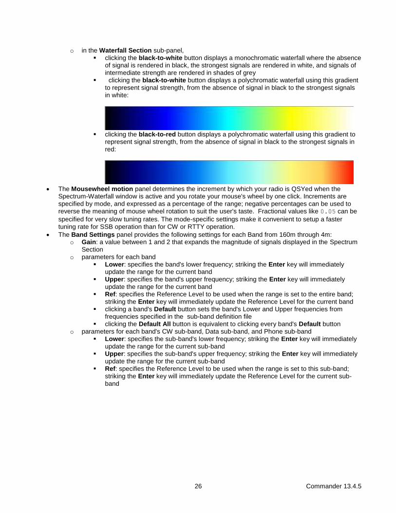
o in the Waterfall Section sub-panel, ▪ clicking the black-to-white button displays a monochromatic waterfall where the absence
of signal is rendered in black, the strongest signals are rendered in white, and signals of intermediate strength are rendered in shades of grey
▪ clicking the black-to-white button displays a polychromatic waterfall using this gradient to represent signal strength, from the absence of signal in black to the strongest signals in white:
▪ clicking the black-to-red button displays a polychromatic waterfall using this gradient to
represent signal strength, from the absence of signal in black to the strongest signals in red:
• The Mousewheel motion panel determines the increment by which your radio is QSYed when the
Spectrum-Waterfall window is active and you rotate your mouse's wheel by one click. Increments are specified by mode, and expressed as a percentage of the range; negative percentages can be used to reverse the meaning of mouse wheel rotation to suit the user's taste. Fractional values like 0.05 can be
specified for very slow tuning rates. The mode-specific settings make it convenient to setup a faster tuning rate for SSB operation than for CW or RTTY operation.
• The Band Settings panel provides the following settings for each Band from 160m through 4m: o Gain: a value between 1 and 2 that expands the magnitude of signals displayed in the Spectrum
Section o parameters for each band
▪ Lower: specifies the band's lower frequency; striking the Enter key will immediately update the range for the current band
▪ Upper: specifies the band's upper frequency; striking the Enter key will immediately update the range for the current band
▪ Ref: specifies the Reference Level to be used when the range is set to the entire band; striking the Enter key will immediately update the Reference Level for the current band
▪ clicking a band's Default button sets the band's Lower and Upper frequencies from frequencies specified in the sub-band definition file
▪ clicking the Default All button is equivalent to clicking every band's Default button o parameters for each band's CW sub-band, Data sub-band, and Phone sub-band
▪ Lower: specifies the sub-band's lower frequency; striking the Enter key will immediately update the range for the current sub-band
▪ Upper: specifies the sub-band's upper frequency; striking the Enter key will immediately update the range for the current sub-band
▪ Ref: specifies the Reference Level to be used when the range is set to this sub-band; striking the Enter key will immediately update the Reference Level for the current sub-band

27 Commander 13.4.5
S-Meter Display
If your transceiver is capable of reporting its S-meter reading via its PC interface, then Commander will continuously display this reading above the VFO's frequency display. By default, the numeric value of this reading is displayed as an integer between 1 and 16. If Commander's Smeter folder contains a text file whose name
matches your transceiver model (as displayed in Commander's title bar), then Commander will use the entries in that file to display textual data rather than integers.
The format of this file is illustrated by the contents of MP1000.txt, which is included in Commander's Smeter
folder:
1, S0
2, S1
3, S2
4, S3
5, S4
6, S5
7, S6
8, S7
9, S8
10,S9
11,S9+10db
12,S9+20db
13,S9+30db
14,S9+40db
15,S9+50db
16,S9+60db
Note that there are exactly 16 entries (lines), each containing an entry number, followed by a comma, followed by textual data; the textual data cannot contain a comma. The following example - the contents of FT817.txt -- illustrates the display of more precise signal level information.
1, < -108 dbm
2, > -108.3 dbm
3, > -107.3 dbm
4, > -106.7 dbm
5, > -106.0 dbm
6, > -105.1 dbm
7, > -104.2 dbm
8, > -103.0 dbm
9, > -100.4 dbm
10,> -84 dbm
11,> -74.5 dbm
12,> -70.1 dbm
13,> -58.9 dbm
14,> -50.8 dbm
15,> -40.8 dbm
16,> -30.1 dbm

28 Commander 13.4.5
By default, the S-meter is rendered as a green bar on a black background. An optional third parameter may be added to each line of an S-meter file to specify the color used to render the S-meter at that signal strength. The color-specifying third parameter can be one of the words black, blue, cyan, green, magenta, red,
white, or yellow. Alternatively, the color-specifying third parameter can be of the form
R-G-B
where R, G, and B are each integers between 0 and 255 that specify the relative content of red, green, and blue in
the desired color. Some examples of valid S-meter file entries that include a color-specifying third parameter follow:
11,S9 + 10db,176-0-0
12,S9 + 20db,192-0-0
13,S9 + 30db,208-0-0
14,S9 + 40db,224-0-0
15,S9 + 50db,240-0-0
16,S9 + 60db,red
29 Commander 13.4.5
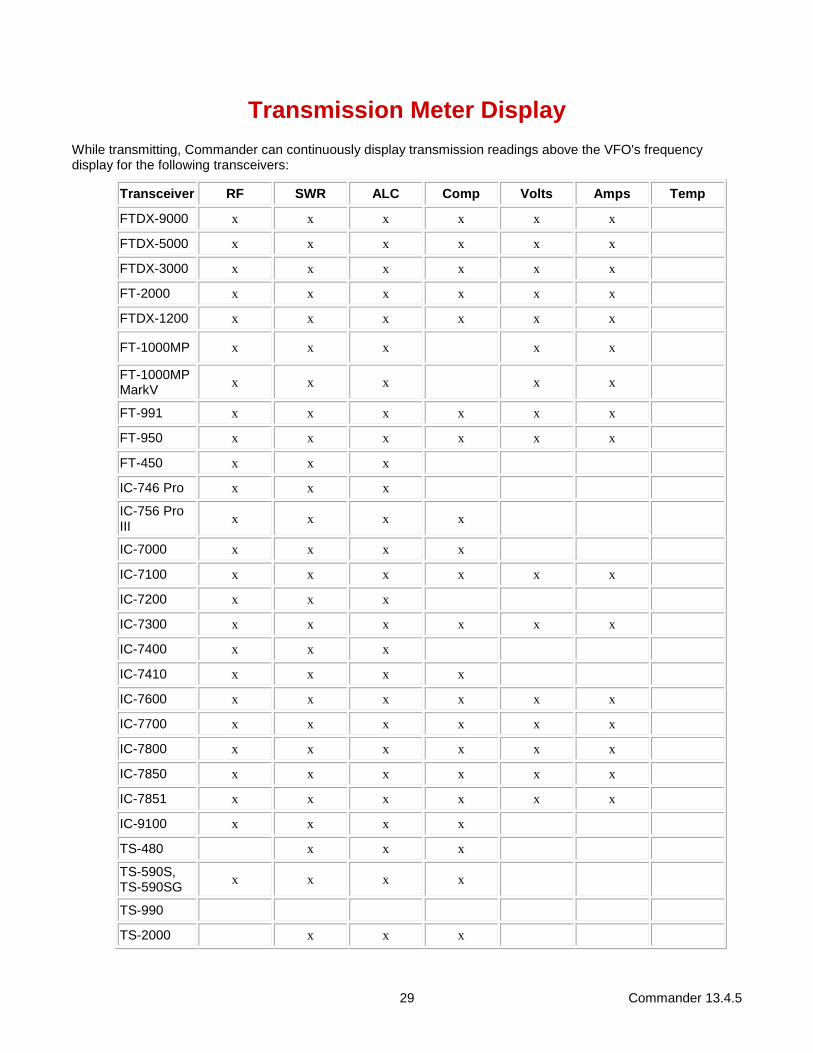
Transmission Meter Display
While transmitting, Commander can continuously display transmission readings above the VFO's frequency display for the following transceivers:
Transceiver RF SWR ALC Comp Volts Amps Temp
FTDX-9000 x x x x x x
FTDX-5000 x x x x x x
FTDX-3000 x x x x x x
FT-2000 x x x x x x
FTDX-1200 x x x x x x
FT-1000MP x x x
x x
FT-1000MP MarkV
x x x x x
FT-991 x x x x x x
FT-950 x x x x x x
FT-450 x x x
IC-746 Pro x x x
IC-756 Pro III
x x x x
IC-7000 x x x x
IC-7100 x x x x x x
IC-7200 x x x
IC-7300 x x x x x x
IC-7400 x x x
IC-7410 x x x x
IC-7600 x x x x x x
IC-7700 x x x x x x
IC-7800 x x x x x x
IC-7850 x x x x x x
IC-7851 x x x x x x
IC-9100 x x x x
TS-480 x x x
TS-590S, TS-590SG
x x x x
TS-990
TS-2000 x x x
30 Commander 13.4.5
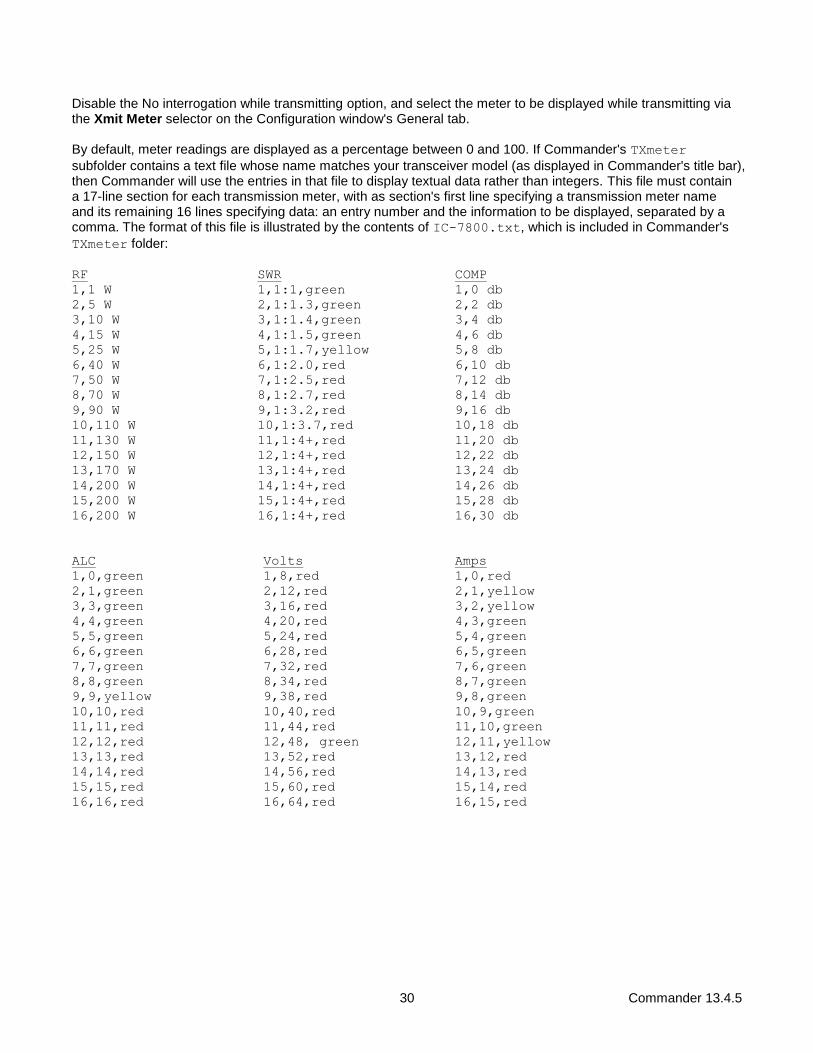
Disable the No interrogation while transmitting option, and select the meter to be displayed while transmitting via the Xmit Meter selector on the Configuration window's General tab.
By default, meter readings are displayed as a percentage between 0 and 100. If Commander's TXmeter
subfolder contains a text file whose name matches your transceiver model (as displayed in Commander's title bar), then Commander will use the entries in that file to display textual data rather than integers. This file must contain a 17-line section for each transmission meter, with as section's first line specifying a transmission meter name and its remaining 16 lines specifying data: an entry number and the information to be displayed, separated by a comma. The format of this file is illustrated by the contents of IC-7800.txt, which is included in Commander's
TXmeter folder:
RF SWR COMP
1,1 W 1,1:1,green 1,0 db
2,5 W 2,1:1.3,green 2,2 db
3,10 W 3,1:1.4,green 3,4 db
4,15 W 4,1:1.5,green 4,6 db
5,25 W 5,1:1.7,yellow 5,8 db
6,40 W 6,1:2.0,red 6,10 db
7,50 W 7,1:2.5,red 7,12 db
8,70 W 8,1:2.7,red 8,14 db
9,90 W 9,1:3.2,red 9,16 db
10,110 W 10,1:3.7,red 10,18 db
11,130 W 11,1:4+,red 11,20 db
12,150 W 12,1:4+,red 12,22 db
13,170 W 13,1:4+,red 13,24 db
14,200 W 14,1:4+,red 14,26 db
15,200 W 15,1:4+,red 15,28 db
16,200 W 16,1:4+,red 16,30 db
ALC Volts Amps
1,0,green 1,8,red 1,0,red
2,1,green 2,12,red 2,1,yellow
3,3,green 3,16,red 3,2,yellow
4,4,green 4,20,red 4,3,green
5,5,green 5,24,red 5,4,green
6,6,green 6,28,red 6,5,green
7,7,green 7,32,red 7,6,green
8,8,green 8,34,red 8,7,green
9,9,yellow 9,38,red 9,8,green
10,10,red 10,40,red 10,9,green
11,11,red 11,44,red 11,10,green
12,12,red 12,48, green 12,11,yellow
13,13,red 13,52,red 13,12,red
14,14,red 14,56,red 14,13,red
15,15,red 15,60,red 15,14,red
16,16,red 16,64,red 16,15,red

31 Commander 13.4.5
By default, a transmission meter is rendered as a green bar on a black background. An optional third parameter may be added to each data line of an transmission meter file to specify the color used to render the transmission meter at that value. The color-specifying third parameter can be one of the words black, blue, cyan,
green, magenta, red, white, or yellow. Alternatively, the color-specifying third parameter can be of the
form
R-G-B
where R, G, and B are each integers between 0 and 255 that specify the relative content of red, green, and blue in
the desired color. Some examples of transmission meter file data lines that include a color-specifying third parameter follow:
6,1:2.0,176-0-0
7,1:2.5,192-0-0
8,1:2.7,208-0-0
9,1:3.2,224-0-0
10,1:3.7,240-0-0
11,1:4+,red

32 Commander 13.4.5
User-defined Controls
Increasingly, modern radios provide for computer control beyond VFO, mode, and filter selection. To provide access to these capabilities, Commander lets you specify
• up to 33 Command Sequences, each containing up to 64 transceiver commands
• up to 16 Command-generating Sliders
To enable access to all Command Sequences and Command-generating Sliders, check the Show by expanding Main window box in the User-defined Controls panel on the General tab of Commander's Configuration window; Commander's Main window will be expanded in height to display a panel containing two rows of eight buttons and two rows of four horizontal slider controls; if you don't need all four rows of buttons and sliders, you can adjust the bottom border of Commander's Main window upward by dragging it with the left mouse button depressed. Alternatively, you can check the Show within Main window box, which will
• display a User-defined Controls panel containing 8 buttons and 4 sliders that can be used to invoke and edit User-defined Controls - setting Commander's Main window to its standard height
• disable all three Frequency-dependent device panels
Each Command Sequence can optionally display a "LED-like display" beneath its button, and specify this LED's color. If you specify Command Sequences or Command-generating Sliders, and are controlling more than one transceiver, you must specify a User-defined Control Set for each transceiver. Command Sequences
A Command Sequence specifies 64 commands, where each command can accomplish one of several things:
• convey an instruction to your transceiver (CAT)
• terminates execution of the sequence
• conditionally or unconditionally change the flow of control within the sequence
• do nothing
• update the caption shown on the button used to activate the sequence
• specify the color displayed by an LED the button used to activate the sequence
• update the contents of the explanatory popup window that appears when the mouse cursor hovers over the button used to activate the sequence
Command Sequences are numbered 1 through 32, and organized as two banks of sixteen sequences. Two rows of eight buttons are used to activate the sequences in the current bank; you can also activate sequences in the current bank by striking the F5 through F12 function keys for the bank's first row of eight sequences, and SH-F5 through SH-F12 function keys for the bank's second row eight sequences (depress this SHIFT key while striking a function key between F5 and F12). The ALT checkbox located between the sequence buttons determines which bank is current. To switch banks, check or uncheck the ALT checkbox. Depressing the ALT key while clicking a sequence button or striking one of F5 through F12 activates a sequence in the first row of the second bank; depressing the ALT key while clicking a sequence button or depressing both the ALT and SHIFT keys while striking one of F5 through F12 activates a sequence in the second row of the second bank
An Initial Command Sequence can be optionally executed when Commander starts, or when a new radio Model is selected. To define, edit, or test this sequence, click the Edit button in the Initial Command Sequence Panel on the Config window's General tab.

33 Commander 13.4.5
To define, edit, or test a Command Sequence for a button in the User-defined Controls panel, right-click the button; you can also depress the CTRL key while clicking that button or while striking it's associated function key (F5 through F12, as designated above each button). To define a Command Sequence in the second bank, check the ALT box and then right-click the appropriate button, or depress both the ALT and CTRL keys while clicking on the button or while striking its associated function key. Commander will display a window that enables you to name and document a sequence of up to 32 radio commands to be sent to your transceiver when the associated Command Sequence button is clicked, when its associated function key is struck, or when a directive is received from another application (e.g. WinWarbler). Each Command Sequence is composed by a list of 32 Commands and Notes, a Name, and a Function:
Name specifies the name of the sequence; this name serves as the caption on the associated User-defined Command Sequence button, so choose a name of appropriately-short length
• if you plan to use conditional branching commands (see Command table below), the name cannot contain a comma
Note: if you wish to include the ampersand character in the name, use a pair of back-to-back ampersands, e.g. R&&B.
Commands • click the 1 - 32 button to display the first 32 commands in the sequence
• click the 33 - 64 button to display the second 32 commands in the sequence
LED Display if the Enabled box is checked, a LED-like display appears beneath the associated User-defined Command Sequence button; the color displayed by this LED is specified by the Initial Color selector
Function describes the function of the Command Sequence; this information will appear in a popup explanation window when the mouse cursor lingers above the associated Command Sequence button if the display of control explanations is enabled.
Command (1-32) a sequence of radio commands to be executed, beginning with Command 1
Note (1-32) optional information used to document the associated command; this information is not sent to your radio
Valid commands are enumerated in the following table:
Command Function
an even number of hexadecimal characters, e.g.
FEFE26E00700FD
hexadecimal radio command -- characters are sent to your radio via the primary CAT serial port, two per byte (useful for Icom, TenTec, and Yaesu radios)
• substitution strings: slider value, CI-V address
• execution proceeds with the following command.
a sequence of ascii characters preceded by a single apostrophe, e.g.
'AN1;
ASCII radio command -- each character following the apostrophe will be sent to your radio via the primary CAT serial port (useful for Kenwood and Elecraft radios)
• substitution strings: slider value, ascii character
• execution proceeds with the following command.
a sequence of ascii characters preceded by a single tilde, e.g.
~slice set 0 rxant=ant1
ASCII radio command -- each character following the tilde will be sent to your radio via the TCP/IP connection (useful for Flex Signature radios)
• substitution strings: slider value, ascii character
• execution proceeds with the following command.

34 Commander 13.4.5
<DataSignalsEnable On>
<DataSignalsEnable Off>
<DataSignalsEnable On> checks the Parallel Port Data Signals panel's Enable box, thereby enabling frequency-based control of the parallel port data output. <DataSignalsEnable Off> un-checks the Parallel Port Data Signals panel's Enable box, thereby disabling frequency-based control of the parallel port data output. When the value of the Parallel Port Data Signals panel's Enable box is changed by either of these commands, the new Enable box setting is not saved in the Windows Registry.
<Band mHz> activates the Bandspread window's Band Stack for the specified band, setting the radio's frequency to the most recent frequency used on that band, setting its mode to the mode in use at that time, and clearing Split
mHz Band
1 160 m
3 80 m
5 60 m
7 40 m
10 30 m
14 20 m
18 17 m
21 15 m
24 12 m
28-29 10 m
50-53 6 m
70 4 m
144-147 2 m
222-224 1.25 m
420-449 70 cm
902-927 33 cm
For example, the command <Band 14> will QSY to the most recent 20m frequency and mode, and clear Split.
<Dual On>
<Dual Off>
enables or disables the current transceiver's Dual Receive
<End> termination
• execution of the Command Sequence terminates.
<FreqDepDevEnable On, N>
<FreqDepDevEnable Off, N>
<FreqDepDevEnable On, N> enables Frequency-dependent Device N, where N is a number the range of 0 to 2. <FreqDepDevEnable Off, N> enables Frequency-dependent Device N, where N is a number the range of 0 to 2. If the specified frequency-dependent device is disabled, <FreqDepDevEnable On, N>loads the device's data from the Data File pathname specified on the device's tab on the Configuration window

35 Commander 13.4.5
<Goto N> unconditional branch
• execution proceeds with command N.
• be careful to avoid an infinite loop
<IfBand bandname, N> conditional branch based on the current transceiver's current band
• if the current transceiver's current band is bandname, then execution proceeds with command N
• if the current transceiver's current band is not bandname, then execution proceeds with the following command
• bandname is a valid band name specified in the current sub-band definition file; the names 1.25m, 33cm, and 23cm are also accepted
• be careful to avoid an infinite loop
<IfLED color, N> conditional branch based on the Command Sequence's current LED color
• if the Command Sequence's LED color is color, then execution proceeds with command N
• if the Command Sequence's LED color is not color, then execution proceeds with the following command
• be careful to avoid an infinite loop
<IfMode modename, N> conditional branch based on the current transceiver's mode as last reported to Commander
• if the current transceiver's last reported mode is modename, then execution proceeds with command N
• if the current transceiver's last reported mode is not modename, then execution proceeds with the following command
• modename is AM, CW, CW-R, Data-L, Data-U, FM, LSB, PKT, PKT-R, RTTY, RTTY-R, USB, or WBFM
• be careful to avoid an infinite loop
<IfName name, N> conditional branch based on the Command Sequence's current button caption
• if the Command Sequence's button caption is name, then execution proceeds with command N
• if the Command Sequence's button caption is not name, then execution proceeds with the following command
• the comparison between button caption and name is case-independent.
• name can contain spaces, but not a comma
• be careful to avoid an infinite loop
<IfRadioName name, N> conditional branch based on the current primary transceiver's name
• if the current primary transceiver's name is name, then execution proceeds with command N
• if the current primary transceiver's name is not name, then execution proceeds with the following command
• the comparison between the current primary transceiver's name and name is case-independent.
• name can contain spaces, but not a comma
• be careful to avoid an infinite loop

36 Commander 13.4.5
<IfSeqName Q, name, N> conditional branch based on the specified Command Sequence's current button caption
• Q is a number between 0 and 31 that specifies one of the 32 Command Sequences (0 for command sequence #1, 1 for command sequence #2, etc)
• if the specified Command Sequence's button caption is name, then execution proceeds with command N
• if the specified Command Sequence's button caption is not name, then execution proceeds with the following command
• the comparison between button caption and name is case-independent.
• name can contain spaces, but not a comma
• be careful to avoid an infinite loop
<IfSplit N> conditional branch based on whether the current transceiver is operating split
• if the current transceiver is operating split, then execution proceeds with command N
• current transceiver is not operating split, then execution proceeds with the following command
<LED color> sets the current Command Sequence's LED color to color
• color can be red, blue, green, black, white, yellow, cyan, or magenta
<LED Q, color> sets the specified Command Sequence's LED color to color
• color can be red, blue, green, black, white, yellow, cyan, or magenta
• Q is a number between 0 and 31 that specifies one of the 32 Command Sequences (0 for command sequence #1, 1 for command sequence #2, etc)
<Mode modename> sets the current transceiver's mode to modename
• modename is AM, CW, CW-R, DATA-L, DATA-U, DIGL, DIGU, FM, LSB, PKT, PKT-R, RTTY, RTTY-R, USB, or WBFM
<Name text> sets the current Command Sequence's button caption to text
<Name Q, text> sets the specified Command Sequence's button caption to text
• Q is a number between 0 and 31 that specifies one of the 32 Command Sequences (0 for command sequence #1, 1 for command sequence #2, etc)
<ParData N> sets the specified parallel port's eight data bits (pins 9 through 2) to the least significant 8 bits of N
<ParClearBit B> clears the specified parallel port's data bit B
• B is a value between 7 and 0
• B=7 selects pin 9; B=0 selects pin 2
• clearing a data bit sets its output to ~0 VDC
• after starting Commander, at least one <ParData N> command must be executed before executing a <ParClearBit B> command
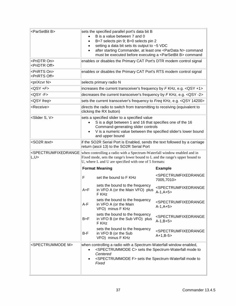
37 Commander 13.4.5
<ParSetBit B> sets the specified parallel port's data bit B
• B is a value between 7 and 0
• B=7 selects pin 9; B=0 selects pin 2
• setting a data bit sets its output to ~5 VDC
• after starting Commander, at least one <ParData N> command must be executed before executing a <ParSetBit B> command
<PriDTR On>
<PriDTR Off>
enables or disables the Primary CAT Port's DTR modem control signal
<PriRTS On>
<PriRTS Off>
enables or disables the Primary CAT Port's RTS modem control signal
<priXcvr N> selects primary radio N
<QSY +F> increases the current transceiver's frequency by F KHz, e.g. <QSY +1>
<QSY -F> decreases the current transceiver's frequency by F KHz, e.g. <QSY -2>
<QSY freq> sets the current transceiver's frequency to Freq KHz, e.g. <QSY 14200>
<Receive> directs the radio to switch from transmitting to receiving (equivalent to clicking the RX button)
<Slider S, V> sets a specified slider to a specified value
• S is a digit between 1 and 16 that specifies one of the 16 Command-generating slider controls
• V is a numeric value between the specified slider's lower bound and upper bound
<SO2R text> if the SO2R Serial Port is Enabled, sends the text followed by a carriage return (ascii 13) to the SO2R Serial Port
<SPECTRUMFIXEDRANGE L,U>
when controlling a radio with a Spectrum-Waterfall window enabled and in
Fixed mode, sets the range's lower bound to L and the range's upper bound to
U, where L and U are specified with one of 5 formats:
Format Meaning Example
F set the bound to F KHz <SPECTRUMFIXEDRANGE 7005,7010>
A+F sets the bound to the frequency in VFO A (or the Main VFO) plus F KHz
<SPECTRUMFIXEDRANGE A-1,A+5>
A-F sets the bound to the frequency in VFO A (or the Main VFO) minus F KHz
<SPECTRUMFIXEDRANGE A-1,A+5>
B+F sets the bound to the frequency in VFO B (or the Sub VFO) plus F KHz
<SPECTRUMFIXEDRANGE A-1,B+5>
B-F sets the bound to the frequency in VFO B (or the Sub VFO) minus F KHz
<SPECTRUMFIXEDRANGE A+1,B-5>
<SPECTRUMMODE M> when controlling a radio with a Spectrum-Waterfall window enabled,
• <SPECTRUMMODE C> sets the Spectrum-Waterfall mode to Centered
• <SPECTRUMMODE F> sets the Spectrum-Waterfall mode to Fixed

38 Commander 13.4.5
<SPECTRUMREFLEVEL R>
when controlling a radio with a Spectrum-Waterfall window enabled, sets the curent Reference Level to R db without changing the reference level associated with the current band or sub-band
<Split On>
<Split Off>
enables or disables the current transceiver's Split
<Tooltip text> sets the current Command Sequence button's popup explanation to text
<Tooltip Q, text> sets the specified Command Sequence button's popup explanation to text
• Q is a number between 0 and 31 that specifies one of the 32 Command Sequences (0 for command sequence #1, 1 for command sequence #2, etc)
<Transmit> directs the radio to switch from receiving to transmitting (equivalent to clicking the TX button)
<TXMeter MeterName> sets the Xmit Meter selector to the specified MeterName
<XcvrA=B> directs the radio to set the VFO B (or sub-receiver) frequency to the VFO A (or main receiver) frequency
<XcvrAxB> directs the radio to exchange the VFO A (or main receiver) and VFO B (or sub-receiver) frequencies
<Wait> pauses for the duration indicated in the Command Interval textbox after executing the previous transceiver command in the sequence before executing the next transceiver command in the sequence.
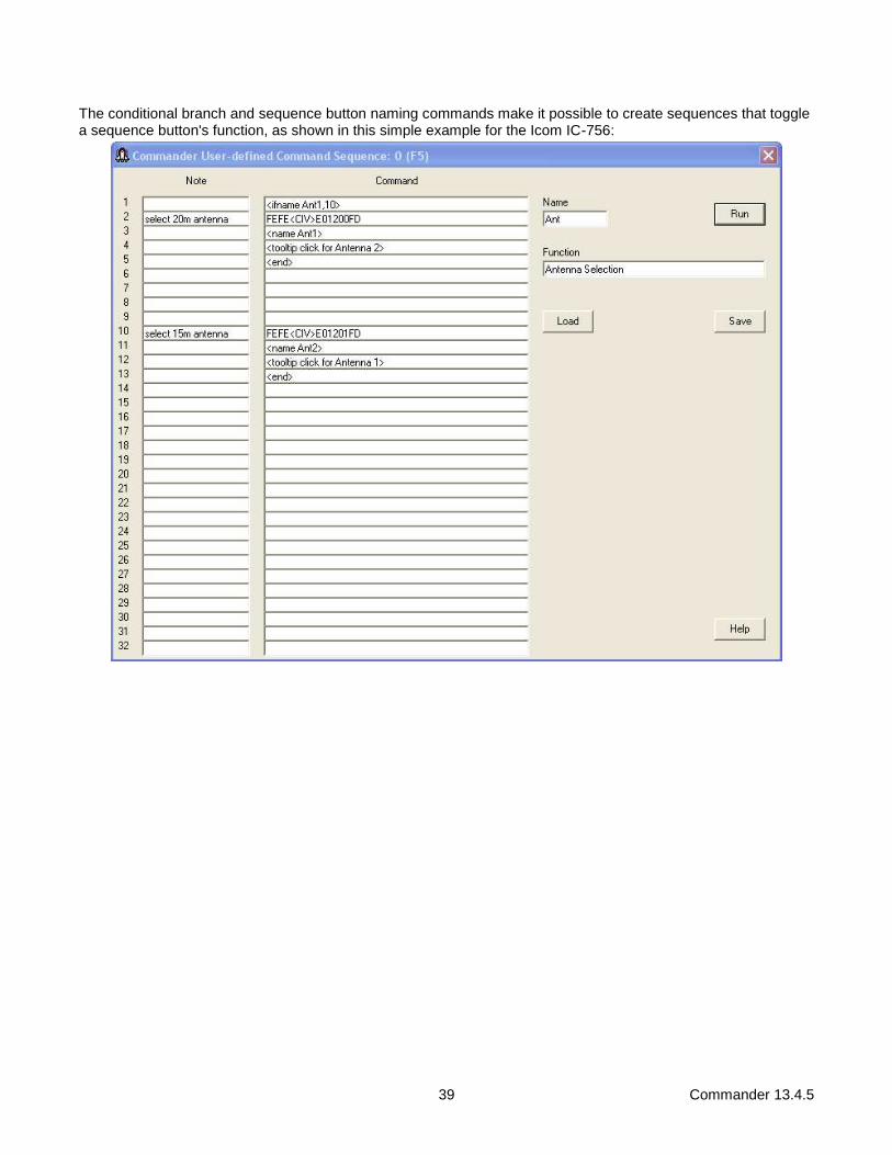
39 Commander 13.4.5
The conditional branch and sequence button naming commands make it possible to create sequences that toggle a sequence button's function, as shown in this simple example for the Icom IC-756:

40 Commander 13.4.5
Using LED color to display the state of a controlled element, in this case an Icom IC-7700's Twin Peak Filter:
The Save and Load buttons enable you to save a Command Sequence to a specified file, and load a Command Sequence from a specified file.
If you are controlling multiple primary transceivers, you can define a user-defined control set that specifies the Command Sequences to be loaded when you switch among primary transceivers. Substitution strings Substitution strings let you insert the value of a command-generating slider, CI-V address, or ascii character into a specified position within a radio command.
41 Commander 13.4.5
The insertion of a slider's value into a template instruction is specified via a substitution string of the form <SFN>, where
• S is an optional* integer between 1 and 16 that specifies one of the 16 command-generating Sliders
• F is a single letter indicating the Format of the inserted value
o D means "decimal digits" with leading zeros
o E means "decimal digits" without leading zeros
o S means "signed decimal digits" o H means "hexadecimal bytes" o B means "unsigned binary bytes"
• N is an optional digit indicating the Number of decimal digits (including the sign in a signed decimal format) or hexadecimal bytes to insert; when not present, a single decimal digit or hexadecimal byte or binary byte is inserted. For unsigned binary bytes, N is limited to the values 1 or 2.
For example, the command FEFE6EE01401<2D4>FD will use the current value of slider 2 to set an Icom 756 Pro III's AF gain. The S is only optional when the substitution string appears in the Command of a command-generating slider's Configuration window; in this case, the slider's own value is used, as shown in the screenshot in the section below.
The substitution string <CIV> is replaced hexadecimal radio commands by the current transceiver's specified CI-V address. Thus, the command FEFE<CIV>E01401<2D4>FD will be executed by the transceiver whose CI-V address is specified in the Radio panel on the Configuration window's General tab.
When controlling a Flex Signature transceiver, the substitution string <FlexSigPanStream> is replaced by the hexadecimal ID of VFO A's panadapter. This ID is required by some of the commands used to control a Flex Signature transceiver. The substitution string <n> (where n is an integer between 0 and 127) is replaced in ASCII radio commands by a single character whose ascii value is n; for example, <13> will be replaced by the "carriage return" character.
Command-generating Sliders
One can set the AF gain of a Kenwood TS-2000 by sending it the ASCII command AG0NNN; where NNN is a 3-digit decimal number between 0 and 255 that specifies the desired gain. One can set the AF gain of an Icom 756 Pro III by sending it the hexadecimal command FEFE6EE01402XXXXFD when XXXX is a 4-digit decimal number between 0 and 255. A Command-generating Slider lets you "fill in" the NNN or XXXX with an appropriate value determined by the handle position of a horizontal slider control in Commander's User-defined Commands panel. To control a TS-2000's AF gain with a slider control, one must at minimum configure the slider with
• a lower bound
• an upper bound
• a specification of where and how the slider's value will be inserted into the command

42 Commander 13.4.5
This information is captured by the slider's Configuration window, which can be made to appear by double-clicking the label beneath the slider control:
The <D3> substitution command does not specify a Slider number, so Slider 1's value is used (because this is Slider 1's configuration)
Lower bound
the slider's value when its handle is positioned to the extreme left
Upper bound
the slider's value when its handle is positioned to the extreme right
Small step
the amount by which the slider's value is decreased or increased when you click the arrow at its extreme left or extreme right, respectively
Big step
the amount by which the slider's value is decreased or increased when you click the in the space to the left or the right of its handle, respectively
Label
text that will appear immediately below the slider
• the string <value> will be replaced by the slider's current numeric value
• the string <value U> (where U is a number) will be replaced by the slider's current numeric value scaled into the range between 0 and U
• the string <value L, U> (where L and U are numbers) will be replaced by the slider's current numeric value scaled into the range between L and U
Function
text that will appear in an explanatory popup window if the mouse cursor hovers above the label immediately below the slider
• the string <value> will be replace by the slider's current numeric value
Command
a hexadecimal or ASCII radio command that includes a substitution string specifying where and how the slider's value is inserted to create a command that is sent to the transceiver
• when Commander starts
• when a new transceiver is selected (if Commander is configured to control multiple transceivers)
• whenever the slider's value is changed
Initialize Radio
when checked, the generated slider command is sent to the radio on startup, or after switching radios

43 Commander 13.4.5
A slider's value is changed by
• dragging it's handle left or right,
• clicking its left-arrow or right-arrow
• clicking the space to the left or right of its handle
• executing a <slider> command in a Command Sequence
• a frequency-dependent device control configured to drive the slider
• receiving a directive from another application (e.g. WinWarbler). In the example shown in the above screenshot of Commander User Slider 4's Configuration window, the ASCII command AG0000; will be generated when slider 4's handle is moved to the extreme left, the ASCII command AG0255; will be generated when slider 4's handle is moved to the extreme right, and the ASCII command AG0128; will be generated when slider 4's handle is centered.
Note that while the CI-V commands used to control Icom transceivers are expressed in hexadecimal, variable settings must often be expressed in decimal. For example, the template used to control an Icom 756 Pro III's AF gain with slider #2 is FEFE6EE01401<2D4>FD (with a lower bound of 0 and an upper bound of 255) . In contrast, using slider #5 to select a Yaesu FT-1000MP's mode would be accomplished with 000000<5H>0C (with a lower bound of 0 and an upper bound of 11). Only the signed decimal and hexadecimal formats should be used with sliders that can take on negative values. For example, the FlexRadio template 'ZZWB<1S4> will generate commands like ZZWB+028 or ZZWB-014 .
Commander's 16 sliders are numbered 1 through 16 and organized into two banks of 8, which each bank containing two rows of 4 sliders. The same ALT checkbox that switches between banks of Command Sequences also switches between banks of sliders.
When clicked, the Save button saves the slider definition to a file you specify; the slider definition includes the slider's current value. The Load button loads the slider definition from a file you specify and sets the slider to the value saved in the file. If you are controlling multiple primary transceivers, you can define a user-defined control set that specifies the Command-generating Sliders to be loaded when you switch among primary transceivers.

44 Commander 13.4.5
Changing Frequency
Using Commander, you can change your transceiver's frequency by
• activating controls on the Main window's VFO panel
• rotating your mouse's wheel
• striking keyboard shortcuts
• selecting a memory
• scanning memories in the current memory bank
• actions in the Bandspread window
• actions in the Spectrum-Waterfall window If you have configured Commander to support automatic switching between multiple transceivers, then the above actions may trigger a switch from one transceiver to another when a new amateur band frequency is specified.
If you have configured one or more frequency-dependent device, the settings for these devices will be continuously updated as a function of frequency. The panels displaying these settings reside on the right side of Commander's Main window, along with the secondary VFO, Filter, and PTT panels. This part of the Main window is shared with the Memory Bank panel. If the Memory Bank panel is visible, click the Filters & Devices button and the device panels will appear. You can select one control of one frequency-dependent device whose integer value will be placed on pins 2-9 of a specified parallel port. This can be used to control an antenna switch, for example.
The primary VFO panel on Commander's Main window displays the frequency last reported by your radio, unless a transverter is active; if you have configured Commander to support one or more transverters on the 6m, 4m, 2m, 70cm, 33cm, or 23cm bands, your transceiver will automatically be set to drive the transverter to the frequency specified by Commander's VFO. The primary VFO panel's caption indicates whether the radio is displaying VFO A, VFO B, the Main VFO, or the Sub VFO. For most Elecraft, Kenwood, TenTec, and Yaesu radios, this VFO identification will always be accurate; for Icom and TenTec Omni radios, however, the VFO identification will only be correct if VFO selection is accomplished via the controls on Commander's Main window, rather than via controls on the radio's front panel. You can define up to eight sub-bands per band. You can specify the font colors to be used to display the primary VFO frequency when it lies within a defined sub-band, and when it does not lie within a defined sub-band; you can also specify the background color used to display frequencies in the primary VFO panel.
Commander also displays a secondary VFO panel whose caption indicates whether its contents are those of VFO A, VFO B, the Main VFO, or the Sub VFO; the panel's caption and its contents will only be valid for Icom and TenTec Omni radios if VFO selection and modification is accomplished via Commander, rather than via the radio's front panel. If the secondary VFO panel is not visible, click the Filters & Devices button as described above.
Changing frequency via the primary VFO panel
• Modifying the frequency display contents and striking the Enter key will radio's primary VFO to the specified frequency; modifying the frequency display contents and striking the Esc key will set the frequency display contents to the radio's current frequency.
• The ▲ and ▼ buttons to the left of the frequency display will shift your radio up or down one band. If the Ham Bands box is checked, these buttons sequence among the ham bands and among 1 MHz segments of ham bands wider than 1 Mhz; depressing the CTRL key while clicking these buttons will sequence among the ham bands independent of band width. If the Ham Bands box is not checked, these buttons shift up or down 1 MHz. If you click and hold these buttons, they will autorepeat at a rate governed by the VFO Autorepeat Rate slider. If a User-defined Sequence after Band Change is specified, that sequence will be executed after either of these buttons are clicked.

45 Commander 13.4.5
• The ▲ and ▼ buttons to the right of the frequency display will increase or decrease your radio's frequency as shown in the following table:
Control Keys Change
10 Hz.
Shift 100 Hz.
Ctrl 1 KHz.
Alt 10 KHz.
Ctrl + Alt 100 KHz.
If you click and hold these buttons, they will autorepeat at a rate governed by the VFO Autorepeat Rate slider.
• The horizontal scrollbar below the frequency display allows rapid frequency change within the current band or band segment; the ◄ and ► buttons at either end change frequency down or up as shown in the following table:
Control Keys Change
1 KHz.
Shift 5 KHz.
Ctrl 10 KHz.
Alt 50 KHz.
Ctrl + Alt 100 KHz.
If you click and hold these buttons, they will autorepeat at a rate governed by the VFO Autorepeat Rate slider.
• Depending upon your radio's capabilities, one or more of the following buttons and checkboxes may appear in the VFO panel:
Button Keyboard Function
A SHIFT-F1 selects VFO A
B SHIFT-F2 selects VFO B
A = B SHIFT-F3 sets VFO B to VFO A's frequency
A X B SHIFT-F4 simultaneously sets VFO A to VFO B's frequency and VFO B to VFO A's frequency (available if provide A/B and TF-SET buttons is not enabled)
Main SHIFT-F1 selects the Main VFO
Sub SHIFT-F2 selects the Sub-receiver VFO
M = S SHIFT-F3 sets the Sub VFO to the Main receiver VFO's frequency
M X S SHIFT-F4 simultaneously sets the Main VFO to the Sub-receiver VFO's frequency and the Sub-receiver VFO to the Main VFO's frequency
XFC F1 momentarily exchanges the A and B (or Main and Sub-receiver) VFOs (available if provide A/B and TF-SET buttons is not enabled)
A / B SHIFT-F4 swaps VFO roles (available if provide A/B and TF-SET buttons is enabled)
TF-S F1 momentarily swaps VFO roles (available if provide A/B and TF-SET buttons is enabled, and radio is in split mode)

46 Commander 13.4.5
Split box selects split frequency operation (if using an Icom or TenTec Omni VI transceiver, see the note below)
• selects VFO B or Sub-receiver VFO on entry
• selects VFO A or Main VFO on exit
Dual receive box
selects dual receive or dual watch operation
• selects VFO B or Sub-receiver VFO on entry
• selects VFO A or Main VFO on exit
Dual track box
when enabled, automatically updates the Sub-receiver VFO frequency to match the Main VFO frequency; this option is available if the Dual receive box is checked and the transceiver is
• an Icom IC-7800, a
• an Elecraft K3 with subreceiver installed
• a Yaesu FT-1000D
• a Yaesu FTDX-5000
• a Yaesu FTDX-9000 with the PEP firmware installed
Sat Mode box
sets or clears Satellite Mode when controlling an Icom IC-910H or IC-9100
• if Satellite Mode is cleared, Commander o displays the VFO A and VFO B frequencies o clears Split, and selects VFO A
• if Satellite Mode is set, Commander o displays the MAIN and SUB frequencies o sets Split, and disables the Split box
Note: Some Icom transceiver models label their VFOs A and B; other Icom transceiver models label their VFOs Main and Sub. When the primary transceiver is a TenTec Omni VI or an Icom transceiver with A and B VFOs, Commander assumes that when Split is enabled, VFO A specifies the receive frequency and that VFO B specifies the transmit frequency. When the primary transceiver is an Icom transceiver with Main and Sub VFOs, Commander assumes that when Split is enabled, the Main VFO specifies the receive frequency and that the Sub VFO specifies the transmit frequency.
• The transceiver command buffer overflow message indicates that one or more directives from Commander to your radio have been discarded. This occurs when large frequency changes are attempted by holding down auto-repeating keys or buttons, exceeding the radio's ability to keep up. Recovery in this situation is automatic -- simply click the ok button, wait for your radio to catch up, and continue.
Changing frequency via the secondary VFO panel Modifying the frequency display contents and striking the Enter key will set radio's secondary VFO to the specified frequency. You can specify the font color and background color used to display frequencies in the secondary VFO panel.
Clicking the 1, 2, 5, or 10 quick split button will select split frequency operation, and set the transmit frequency to the receive frequency plus 1 kHz, 2 kHz, 5 kHz, or 10 kHz respectively. Depressing the CTRL key while left-clicking one of these buttons, or right-clicking one of these buttons will select split frequency operation, and set the transmit frequency to the receive frequency minus 1 kHz, 2 kHz, 5 kHz, or 10 kHz respectively. Depressing the SHIFT key while left-clicking one of these buttons will select split frequency operation, and increase the transmit frequency by 1 kHz, 2 kHz, 5 kHz, or 10 kHz respectively. Depressing the SHIFT and CTRL keys while left-clicking one of these buttons, or depressing the SHIFT key while right-clicking one of these buttons will select split frequency operation, and decrease the transmit frequency by 1 kHz, 2 kHz, 5 kHz, or 10 kHz respectively.

47 Commander 13.4.5
Changing frequency via mouse wheel If you have a wheeled mouse, you can QSY your transceiver clicking in Commander's Main VFO panel and then rotating the mouse's wheel.
When you first rotate the wheel after clicking in Commander's Main VFO panel , a cyan-colored horizontal bar will appear over the right-most digit in the primary VFO panel's frequency display; this indicates the rotating the mouse wheel will adjust the transceiver frequency in units of 10 Hz. Clicking the mouse on any other digit position in the primary VFO panel's frequency will shift the cyan horizontal bar to that digit position, indicating that subsequent mouse wheel rotation will adjust the transceiver frequency in the units of that digit position.
Clicking in the secondary VFO panel will provide similar mouse wheel control of the secondary VFO's frequency -- except on the following transceivers, which do not provide the CAT control of their secondary VFO to necessary to implement this capability:
• all Icom models except the IC-7100, IC-7300, IC-7600, IC-7610, IC-7700, IC-7800, IC-7850, IC-7851
• the TenTec Omni V.9 and Omni VI
• the Yaesu FT-747, FT-757, FT-757GXII, FT-817, FT-857, FT-857D, FT-897, and FT-1000D, If inadvertent mousewheel rotation is problematic, check the Ignore Mousewheel box and Commander will no longer QSY your transceiver when you rotate the mouse's wheel.
Note: if the minimum adjustment you can achieve by rotating the mouse wheel is larger than one unit, check to see if you are running the most recent driver for your wheeled mouse.
Changing frequency via the keyboard
• After clicking on the primary VFO's frequency display or the Bandspread window, you can increase or decrease your radio's frequency by striking the PageUp or PageDown keys respectively:
Control Keys Change
10 Hz.
Shift 100 Hz.
Ctrl 1 KHz.
Alt 10 KHz.
Ctrl + Alt 100 KHz.
• After clicking on the VFO panel's frequency display, you can select its contents by striking the Insert or CTRL-A key; any digits subsequently entered will replace the frequency display's contents; strike the Enter key to change your radio's frequency to that shown in the VFO.
Changing frequency via the Bandspread window
Clicking the Main window's Bandspread button displays Commander's Bandspread window, which provides a vertical slide rule dial showing range of frequencies around your radio's current frequency, and optionally a Band panel containing an array of buttons corresponding to the 160m through 2m amateur bands.
The Range panel determines the range of frequencies depicted on the slide rule dial. You can vary this range from 1 kHz to 500 kHz in seven steps; your radio's current frequency will always appear centered in the dial unless one of the current band's edges is visible, in which case the current frequency indicator will move toward the band edge.
You can resize the Bandspread window both vertically and horizontally. The Band panel will appear when the Bandspread window is sufficiently wide. As you reduce the width of the Bandspread window, the number of options available in the Range panel will decrease.
The current frequency indicator in the slide rule dial can be configured to distinguish between in-band and out-of-band frequencies.

48 Commander 13.4.5
Clicking on the dial will QSY your radio's primary VFO to the associated frequency. Double-clicking the dial will QSY your radio to the associated frequency and then reduce the range by one step, unless the range is already 1 kHz. Depressing the Alt button while clicking on the dial will set your radio's secondary VFO to the associated frequency. Any click or double-click in the dial will terminate scanning. Allowing the mouse cursor to hover over the dial will produce a small popup showing the associated frequency to which your radio would be QSY'd if you were to click or double-click.
You can also QSY via the PageUp and PageDown keys.
Commander remembers the last 5 frequencies you visited on each band, and the mode in use for each such visit; this information is stored in a Band Stack associated with each band. If you QSY the radio, and then let it remain on a frequency for longer than the dwell time setting, the new frequency and mode will be saved on the appropriate Band Stack. The Bandspread window's Band panel contains a button for each band between 160m and 33cm. Clicking a band button sets the radio's frequency to the most recent frequency used on that band, sets its mode to the mode in use at that time, and clears Split; the Band Stack is then advanced, so that clicking the same band button a second time sets the frequency/mode to the next-most-recent frequency/mode used on that band. Using this mechanism, you can QSY to the most recent 5 frequencies. The Band panels in the Bandspread and Spectrum-Waterfall windows share the same Band Stack for each band.
Executing the Band command in a User-defined Sequence is equivalent to clicking the Bandspread window's Band button for the band it specifies. If a User-defined Sequence after Band Change is specified, that sequence will be executed after any button in the Band panel is clicked.
The memory used to provide the slide rule dial and Band Stack are freed when the Bandspread window is closed.
Changing frequency via the Spectrum-Waterfall window
If Commander is controlling an Icom IC-7300, IC-7610, IC-7850, and IC-7851 using a direct USB connection with the Primary CAT Port configured for 115,200 baud, checking the Spectrum-Waterfall window box on Configuration window's Bandspread tab will display Commander's Spectrum-Waterfall window. Depressing the CTRL while clicking the Main window's Bandspread button will enable and display the Spectrum-Waterfall window.

49 Commander 13.4.5
The Spectrum-Waterfall window provides a Control Section positioned above four information-bearing sections:
• the Spectrum Section displays realtime spectrum data
• the DX Callsign Section displays active DX station callsigns
• the Frequency Axis Section displays the range of frequencies being displayed in the Spectrum-Waterfall window
• the Waterfall Section displays a history of the spectrum section's realtime spectrum data
In the Control Section,
• the Frequency panel shows the transceiver's current frequency; if operating split, the current receive frequency is shown.
• the DX Rows panel controls the number of rows of DX Callsigns displayed in the DX Callsign Section
• the Band panel contains a button for each band between 160m and 70cm. Commander remembers the last 5 frequencies you visited on each band, and the mode in use for each such visit; this information is stored in a Band Stack associated with each band. If you QSY the radio, and then let it remain on a frequency for longer than the dwell time setting, the new frequency and mode will be saved on the appropriate Band Stack. Clicking a Band panel button sets the radio's frequency to the most recent frequency used on that band, sets its mode to the mode in use at that time, and clears Split; the Band Stack is then advanced, so that clicking the same Band panel button a second time sets the frequency/mode to the next-most-recent frequency/mode used on that band. Using this mechanism, you can QSY to the most recent 5 frequencies. The Band panels in the Bandspread and Spectrum-Waterfall windows share the same Band Stack for each band.
• The Range panel can switch the transceiver between Fixed and Centered spectrum displays. o When the range is Fixed, the Range panel
▪ provides buttons that make the Spectrum-Waterfall window display the entire Band, or a particular sub-band:
Band sets the range to the entire current band
CW sets the range to the current band's CW sub-band
Data sets the range to the current band's Data sub-band
Phone sets the range to the current band's Phone sub-band
▪ provides a Zoom In button that when clicked cuts the range in half and centers it on the transceiver's receive frequency

50 Commander 13.4.5
▪ provides a Zoom Out button that when clicked doubles the range and centers it on the transceiver's receive frequency
▪ displays the range's lower frequency to the left of the Band button, and the range's upper frequency to the right of the Band button, and updates these frequencies if they are changed from the transceiver's front panel
o When the range is Centered, the Range panel provides buttons that set the range to widths from 5 kHz to 1000 kHz, and updates this selection when the range width is changed from the transceiver's front panel
o If you change the range using the transceiver's front panel, the Spectrum-Waterfall window's Range panel will be updated to reflect that change
• The Ref Level slider controls the sensitivity of the transceiver's spectrum display for the current sub-band or band. Changes update the Ref settings in the Spectrum-Waterfall Configuration window's Band Settings panel, and thus are preserved between operating sessions.
• The Gain slider specifies a value between 1 and 2 for the current band that expands the magnitude of signals displayed in the Spectrum Section. Changes update the Gain settings in the Spectrum-Waterfall Configuration window's Band Settings panel, and thus are preserved between operating sessions.
• The rectangular indicator to the left of the SpotCollector button changes color to indicate the maximum degree of need for any active DX station received by SpotCollector but not visible in the Spectrum-Waterfall window's DX Callsign Section
o allowing the mouse cursor to hover over this indicators displays a small popup window showing the most recent and needed, unseen, active DX station's callsign, frequency, mode, and time of arrival
o clicking in this indicator resets its color to that corresponding with unneeded o double-clicking in this indicator sets the transceiver's frequency and mode to that of the most
recent and needed, unseen, active DX station, and terminates scanning.
• Clicking the SpotCollector button on the Bandspread window or on the Spectrum Waterfall window displays SpotCollector's Main window, if SpotCollector is running.
• Clicking the Spectrum Config button displays the Spectrum-Waterfall Configuration window
• Click the Help button displays this section of Commander's documentation In the Spectrum Section, Commander displays spectrum data from the radio for the current range. You can adjust the reference level and gain via sliders in the Control Section. If not split, clicking in this section will set the transceiver frequency to the designated frequency; ALT-clicking will enable split and set the transceiver's transmit frequency to the designated frequency. If split, clicking in this section will set the transceiver's receive frequency to the designated frequency; ALT-clicking will set the transceiver's transmit frequency to the designated frequency. Allowing the mouse cursor to hover for a few seconds over a location in this section will display an explanatory popup with the frequency associated with the location. You can adjust the color used to display the spectrum data and the background color via the Spectrum-Waterfall Configuration window's Colors panel. In the DX Callsign Section, Commander displays active DX stations received from SpotCollector, if running. Between 4 and 32 rows of callsigns can be displayed, as specified in the DX Rows panel; the appearance of a + symbol in this section means that more DX stations could be displayed if the number of rows were increased. Increasing or decreasing the number of rows will increase or decrease the vertical height of the Spectrum-Waterfall window so that the heights of all other sections are unchanged. Settings governing the acquisition, display, management, and handling of active DX stations are shared with the Bandspread window, and provided on the DX Spots panel on the Configuration window's Bandspread tab. Commander's behavior when you click on or hover above a callsign displayed in the DX Callsign Section is described below. If not split and the mouse cursor not above a callsign, clicking in the DX Callsign Section will set the transceiver frequency to the designated frequency; ALT-clicking will enable split and set the transceiver's transmit frequency to the designated frequency. If split and the mouse cursor not above a callsign, clicking in this section will set the transceiver's receive frequency to the designated frequency; ALT-clicking will set the transceiver's transmit frequency to the designated frequency. Allowing the mouse cursor to hover for a few seconds over a location without a callsign will display an explanatory popup with the frequency associated with the location.

51 Commander 13.4.5
In the Frequency Axis Section, Commander displays a horizontal slide rule with frequencies rendered in the specified font color. If not split, clicking in this section will set the transceiver frequency to the designated frequency; ALT-clicking will enable split and set the transceiver's transmit frequency to the designated frequency. If split, clicking in this section will set the transceiver's receive frequency to the designated frequency; ALT-clicking will set the transceiver's transmit frequency to the designated frequency. Allowing the mouse cursor to hover for a few seconds over a location in this section will display an explanatory popup with the frequency associated with the location. In the Waterfall Section, Commander displays a historical record of the spectrum data, with the most recent signals at top, and the oldest signals at the bottom. You can increase or decrease the height of the Waterfall section by increasing or decreasing the height of the Spectrum-Waterfall window; doing so will leave the heights of all other sections unchanged. If not split, clicking in this section will set the transceiver frequency to the designated frequency; ALT-clicking will enable split and set the transceiver's transmit frequency to the designated frequency. If split, clicking in this section will set the transceiver's receive frequency to the designated frequency; ALT-clicking will set the transceiver's transmit frequency to the designated frequency. Allowing the mouse cursor to hover for a few seconds over a location in this section will display an explanatory popup with the frequency associated with the location. You can select the range of colors used to indicate Waterfall signal strength via the Spectrum-Waterfall Configuration window's Colors panel. When the transceiver is not operating split, Commander displays a single vertical frequency marker in the DX Callsign and Frequency Axis sections, its color is set to that specified for the Receive Freq Marker. When operating split, two vertical frequency markers are displayed in the DX Callsign and Frequency Axis sections, one designating the transceiver's receive frequency and the other designating the transceiver's transmit frequency. The colors of these frequency markers are specified on the Spectrum-Waterfall Configuration window's Colors panel. Scrolling a wheeled mouse while the Spectrum-Waterfall window is active will QSY the transceiver as a function of the transceiver's current mode and the mousewheel motion settings. When the range is Fixed and you change bands - by using the transceiver's front panel, by double-clicking on the entry for an active DX station in SpotCollector, by clicking a Band button in the Bandspread or Spectrum-Waterfall window, or by selecting one of Commander's memories,
• if the Mode AutoTrack option is enabled, Commander will set the range to the sub-band associated with the transceiver's mode
• if the Mode AutoTrack option is disabled but the Frequency AutoTrack option is enabled, Commander will set the range to the lowest-frequency sub-band that contains the transceiver's frequency (receive frequency, if split); if the transceiver's frequency is not within any of the new band's sub-bands, then Commander will set the range to the entire band.
• if neither the Mode AutoTrack nor the Frequency AutoTrack option is enabled, Commander will set the range to the sub-band most recently used on that band
When the range is Fixed, the Mode AutoTrack option is enabled, and you change the transceiver's mode, Commander will set the range to the sub-band associated with the transceiver's mode. When the range is Fixed, the Frequency AutoTrack option is enabled, and you QSY out of the current range but still within the current band, Commander will automatically slide the range up or down so that the transceiver's frequency (receive frequency if split) will be visible in the new range.

52 Commander 13.4.5
Viewing and Selecting DX Spots If SpotCollector (version 2.7.4 or later) is running and Commander's Bandspread window or Spectrum-Waterfall window is open, then SpotCollector will automatically send to Commander spots of active DX stations operating on the transceiver's current band that meet SpotCollector's current filter criteria (with the exception that wildcard characters in the Call and DXCC filters are not handled). Commander displays each active DX station on the Bandspread window's slide rule dial and in the Spectrum-Waterfall window unless the active DX station's age exceeds the specified lifetime. The size of the font used to display active DX stations in the Bandspread window can be specified as a function of its slide rule dial range, making it possible to use larger font sizes with smaller ranges. The size of the font used to display active DX stations in the Spectrum-Waterfall window can be independently specified as a function of its range. Active DX station callsigns are color-coded based on settings in the Font Colors panel on the Spot Database Display tab of SpotCollector's Configuration window; callsigns known to participate in the ARRL's Logbook of the World (LotW) and/or hold Authenticity Guaranteed membership in eQSL.cc are highlighted as specified in the Background Colors tab on the Spot Database Display tab of SpotCollector's Configuration window. In the Bandspread window active DX station callsigns that are close together in frequency are separated horizontally to form a list of up to 8 spots. For busy frequencies and a long lifetime, it may be necessary to expand the Bandspread window horizontally to see all of the spots; alternatively, zooming in to a smaller dial range may separate the spots, or a smaller spot font size can be specified. The appearance of a + at the right of a callsign means that additional callsigns have been spotted on or near the frequency. In the Spectrum-Waterfall window, active DX station callsigns that are close together in frequency are separated vertically in up to 32 rows. For busy frequencies and a long lifetime, it may be necessary to expand the Spectrum-Waterfall window horizontally to see all of the spots; alternatively, zooming in to a smaller dial range may separate the spots, or a smaller spot font size can be specified. The appearance of a + below a callsign means that additional callsigns have been spotted on or near the frequency; you can increase or decrease the number of rows displayed via the DX Rows panel on Spectrum-Waterfall window.
• allowing the mouse cursor to hover over an active DX station callsign displays a small popup window showing the spot's callsign, transmit frequency, QSX (listening) frequency if operating split, mode, UTC time last spotted, LotW participation, areas from which the station was spotted, and spot notes
• clicking on an active DX station callsign in the Bandspread or Spectrum-Waterfall window will o if WinWarbler is not running, or if WinWarbler is running but the station's mode is CW, SSB, AM,
or FM and Commander has been configured to not route spots in this mode to WinWarbler ▪ if the station is operating simplex
o set the radio to the spot's frequency and the appropriate mode (as specified by the CW mode and RTTY mode panels)
o configure the radio for simplex operations (disable split and dual mode, if available)
▪ if the station is operating split and the set Xcvr split option is enabled o set the radio's VFOs to the appropriate transmit and receive frequencies o set the radio to the appropriate mode (as specified by the CW mode and RTTY
mode panels) o configure the radio for split operations (enable split and dual mode, if available)
o if WinWarbler is running ▪ if the station is operating PSK31, PSK63, or RTTY, direct WinWarbler to the specified
mode and optimal frequency; ▪ if the station is operating CW, SSB, AM, or FM and Commander has been configured to
route spots in this mode to WinWarbler, direct WinWarbler to the specified mode and frequency
▪ if the station is operating split, the set Xcvr split option determines whether QSX frequency is conveyed to WinWarbler; if not, WinWarbler will not direct Commander to configure the radio for split frequency operations

53 Commander 13.4.5
• direct DXKeeper (if running) to o initialize its Capture window with the DX spot's callsign, frequency, mode, and gridsquare (if
available) o filter its Log Page Display to show all previous QSOs with the DX spot's callsign or DXCC entity,
as specified by the Log Filter setting
• if both DXView and DXKeeper are running o direct DXView to perform a lookup of the DX spot callsign o if the CTRL key was depressed while clicking on the DX spot, rotate the antenna to the short path
bearing to the spotted station o if the ALT key was depressed while clicking on the DX spot, rotate the antenna to the long path
bearing to the spotted station
• double-clicking an active DX station callsign in the Bandspread window performs all of the operations described above under single-clicking, and then reduces the slide rule dial range by one step, unless the range is already 1 kHz.
When the radio QSYs from one band to another with the Bandspread and/or Spectrum-Waterfall windows open, Commander clears the active DX station callsigns from the Bandspread window and Spectrum-Waterfall window, and SpotCollector sends Commander each Spot Database entry on the new band that meet its current filter criteria (subject to the above-mentioned wildcard character limitation). Thus Commander always displays that subset of SpotCollector's filtered Spot Database entries that are operating in the range of frequencies shown on the Bandspread window and on the Spectrum-Waterfall window Commander displays a rectangular indicator in the lower-left corner of the Bandspread window, and in the upper-right corner of the Spectrum-Waterfall window. The color of the rectangle in the Bandspread window indicates the maximum degree of need for any active DX station received by SpotCollector but not visible on the Bandspread window's slide rule dial. Similarly, the color of the rectangle in the Spectrum-Waterfall window indicates the maximum degree of need for any active DX stations received by SpotCollector but not visible on the Waterfall-Spectrum window.
• allowing the mouse cursor to hover over one of these rectangular indicators displays a small popup window showing the most recent and needed unseen active DX station's callsign, frequency, mode, and time of arrival
• clicking a rectangular indicator resets its color to that corresponding with unneeded
• double-clicking a rectangular indicator sets the radio's frequency and mode to that of the most recent and needed unseen active DX station, and terminates scanning.
Clicking the SpotCollector button on the Bandspread window or on the Spectrum Waterfall window activates SpotCollector's Main window, if SpotCollector is running. The memory used to maintain and display active DX spots is freed when the Bandspread window and Spectrum-Waterfall windows are both closed.

54 Commander 13.4.5
Changing Mode and Filter Setting
Buttons representing the modes supporting by your radio appear in the Main window's Mode panel, and identify the radio's current mode. To change your radio's mode, click the appropriate button in the Mode panel. You can also change your radio's mode by selecting a memory. If your radio supports Filter Groups and the restore Filter Group on mode change box is checked, the caption on each mode button will indicate the last Filter Group used in that mode. In this case, clicking a mode button both directs your radio to change mode, and establishes receiver bandwidth settings specified by that Filter Group.
LSB selects lower sideband modulation
USB selects upper sideband modulation
CW selects continuous wave
CW-R selects continuous wave, reversed
RTTY selects radioteletype
RTTY-R selects radioteletype, reversed
FM selects frequency modulation
WBFM select wide-band frequency modulation
AM selects amplitude frequency modulation
PKT selects packet
PKT-R selects packet, reversed
Data-L selects data mode, lower sideband
Data-U selects data mode, upper sideband
When an Elecraft K3 transceiver's mode is changed to RTTY or RTTY-R, its data mode is set to FSK D or AFSK A as specified in the RTTY sub-mode panel. When an Icom IC-7600, IC-7700, or IC-7800 transceiver's mode is changed to Data-L or Data-U, its data sub-mode is set to D1, D2, or D3 as specified in the Data sub-mode panel. If you are using PKT or PKT-R to log digital-mode QSOs in DXKeeper without running a digital mode application like WinWarbler or MultiPSK, use the Log Mode for PKT or PKT-R setting to specify the digital mode to be logged. If you are using Data-L or Data-U to log digital-mode QSOs in DXKeeper without running a digital mode application like WinWarbler or MultiPSK, use the Log Mode for Data-L or Data-U setting to specify the digital mode to be logged.

55 Commander 13.4.5
Changing Receiver Bandwidth
Radios differ in the degree to which they permit receiver bandwidth to be controlled from PC software. If Commander provides bandwidth controls for the current the radio Model, they are presented in the Filters panel on the right side of the Main window, sharing space with the Memory Bank panel; if the Filters panel is not visible, click the Filters & Devices button. Commander uses the concept of a Filter Group to bridge these disparate capabilities: a Filter Group is a named configuration of one or more receiver bandwidth settings. If Filter Groups are supported for a particular radio Model, Commander remembers the Filter Group last used in each mode. Checking the restore Filter Group on mode change box directs Commander to automatically restore the last used Filter Group whenever a new mode is selected. Elecraft Transceivers
For the Elecraft K3 and KX3, Commander's Main window's Filters panel provides Width and Shift controls. Clicking the X button to the right of the Width slider selects the default filter widths for each mode. Clicking the X button to the right of the Shift slider centers the current filter; you can set the Shift control's resolution to 10 Hz or 50 Hz. The Main window's Filters panel also provides Group selector that lets you quickly choose pre-set Wide, Normal, or Narrow width and shift settings that you've defined for the SSB, CW, Data-L, Data-U, RTTY, and AM modes on the Configuration window's Filter Groups tab. Enabling the restore Filter Group on mode change setting on this tab causes Commander to remember the last Filter Group used in each mode, parenthetically display each mode's last Filter Group in the Main window's Mode panel, and automatically select a mode's last Filter Group when the mode becomes active.
Flex Signature (6000) Transceivers When controlling a Flex Signature transceiver, Commander's Main window's Filters panel provides Width , High-cut, and Low-cut controls. The Main window's Filters panel also provides Group selector that lets you quickly choose pre-set Wide, Normal, or Narrow width and shift settings that you've defined for the SSB, CW, DIGL, DIGU, RTTY, and AM modes on the Configuration window's Filter Groups tab.
Icom Transceivers
Early Icom transceivers provide two Filter Groups, whose functions are hardwired: group 1 provides a wide bandwidth filter, and group 2 provides a narrow bandwidth filter. Later Icom transceivers allow the user to reconfigure one or both filter groups to a different bandwidth (by physical replacement, or in high-end transceivers via menu selection), and some include a third group ambiguously referred to as normal. The Icom Filter Group Names panel lets you assign names to each group that are meaningful for the actual filter configuration of your transceiver. With the radio Model set to an Icom transceiver, the Main window's Filters panel presents a Group selector with the choices whose names you've specified. You can activate a Filter Group by selecting its name in the Group selector on the Main window's Filter panel. When you change filters via the radio's front panel, the Group selector is updated to reflect your choice. Enabling the restore Filter Group on mode change setting on this tab causes Commander to remember the last Filter Group used in each mode, parenthetically display each mode's last Filter Group in the Main window's Mode panel, and automatically select a mode's last Filter Group when the mode becomes active.
For the Icom IC-756ProIII, IC-7000, IC-7200, IC-7300, IC-7600, IC-7700, IC-7800, IC7850, and IC-7851, the Filters panel also provides Width, PBT1, and PBT2 controls; PBT1 corresponds to the transceiver's "inner" PBT knob, and PBT2 corresponds to its "outer" PBT knob. Clicking the X button to the right of the Width slider selects the default filter width for the current mode. Clicking the X button to the right of either PBT control centers that control, eliminating any shift.

56 Commander 13.4.5
Kenwood Transceivers
The Filters panel on Commander's Main window provides mode-specific receiver bandwidth controls for the TS-480, TS-570D, TS-570S, TS-870, and TS-2000 as shown in the following table:
Transceiver SSB CW, CW-R RTTY, RTTY-R
AM FM
TS-480 High-cut, Low-cut
Shift, Width Width High-cut, Low-cut
TS-570S, TS-570D High-cut, Low-cut
Shift, Width Shift, Width High-cut, Low-cut
High-cut, Low-cut
TS-870 High-cut, Low-cut
Shift, Width Width Width
TS-2000 High-cut, Low-cut
Shift, Width Width High-cut, Low-cut
TenTec Transceivers
For the TenTec Orion and Orion II, the Main window's Filters panel provides Width and Shift controls.
Clicking the X button to the right of the Width slider selects the default filter width for the current mode. You can specify the default filter width on the Config window's Filter Groups tab. You can optionally configure Commander to select the default filter width whenever the transceiver changes mode.
Clicking the X button to the right of the Shift control centers that control, eliminating any shift.
Yaesu Transceivers
Commander's Main window's Filters panel provides comprehensive bandwidth control for the Yaesu 1000MP family, including the MarkV and MarKV Field. The Filters panel provides controls that allow direct selection of 2nd IF, 3rd IF, and sub-receiver filters. With the radio Model set to MP1000 or MP1000MKV, the Config window's
Filter Groups tab lets you define 12 Filter Groups, specifying a name, mode, 2nd IF filter, 3rd IF filter, and sub-receive filter for each; you can revise or delete these definitions, and provide new ones. You can activate a Filter Group by selecting its name in the Group selector on the Main window's Filter panel. When you change filters via the radio's front panel, Commander determines whether the new filter configuration matches a defined Filter Group; if so, the Group selector is updated to show the name of the matching Filter Group. Enabling the restore Filter Group on mode change setting on this tab causes Commander to remember the last Filter Group used in each mode, parenthetically display each mode's last Filter Group in the Main window's Mode panel, and automatically select a mode's last Filter Group when the mode becomes active.
For the Yaesu FT-450, FT950, FT-2000, and FT-9000, the Main window's Filters panel provides Width and Shift controls. Clicking the X button to the right of the Width slider selects the default filter width for the current mode. Clicking the X button to the right of the Shift control centers that control, eliminating any shift.

57 Commander 13.4.5
Using Memories
Commander provides 100 memories, organized into ten banks of 10. Memories in the currently-selected memory bank appear in a panel that shares the right side of Commander's Main window with readouts for frequency-dependent devices and receiver filter controls. This panel also contains a button for each memory bank that, when clicked, selects that memory bank and displays its memories. If the currently-selected memory bank is not visible, click the Main window's Mem button to make it appear in place of the device and bandwidth controls. Within a memory bank, each memory stores a frequency, mode, and filter setting.
• Clicking on a memory's Save button saves your radio's current frequency, mode, and filter setting in that memory, as well as the state of Commander's Split, Ham bands only, and Dual receive checkboxes (if those functions are supported by your radio); to protect memories from inadvertent modification, the Save buttons can be disabled.
• You can edit any memory's frequency, mode, and filter setting using standard Window's gestures and keystrokes.
• After clicking on a memory's frequency display, you can select its contents by striking the Insert key; any digits subsequently entered will replace the frequency display's contents.
• Clicking on a memory's Sel button will set your transceiver to that memory's frequency, mode, and filter setting if the frequency and mode are valid, and will set Commander's Split, Ham bands only, and Dual receive checkboxes to the values stored in that memory (if those functions are supported by your transceiver). Commander disables the Sel buttons associated with memories that do not contain a valid frequency and mode.
• You can specify the font color and background color used to display frequencies. By editing textboxes in the Memory Banks panel on the Configuration window's Memories tab, you can establish a title for each memory bank ; the title for the currently-selected memory bank serves as the caption of the Main window panel that displays the currently-selected memory bank. To quickly edit a memory bank's title, depress the Ctrl key while clicking that memory bank's button. To help keep track of each memory's purpose, you can record notes that pop up whenever the mouse cursor hovers over the memory's Sel button. To record such notes, depress the Ctrl key while clicking the Sel button; Commander will display a Memory Notes Editor window that allows you to capture notes:
• notes may not contain the angle bracket characters < or > .
• clicking the Notes Editor's Insert Timestamp button appends a the current UTC date and time to the notes
You can direct Commander to display each memory's notes in place of its frequency, mode, and filter -- simply click the command button captioned ~ in the upper right corner of the memory bank panel. To return to a display of memory frequency, mode, and filter, click the ~ button again. To clear a memory's frequency, mode, filter setting, and notes, depress the Ctrl key while clicking the Save button. To continuously scan valid memories in the current bank, check the Scan box on the Main window. With memory scanning enabled, Commander will sequentially activate each of the current bank's memories that contain a valid frequency and mode, skipping memories not containing a valid frequency or mode. The time between activations is defined by the Scan Dwell setting. If none of the current bank's memories are valid, Commander will uncheck the Scan box and stop scanning. While scanning, the following actions will uncheck the Scan box and stop scanning:
• clicking in the Bandspread window's frequency dial
• double-clicking the Bandspread window's SpotCollector Alert indicator
• receipt of a QSY directive from another application

58 Commander 13.4.5
To save the information associated with all memories that contain at least a frequency and mode, click the Export Memories button on the Configuration window's Memories tab. Commander will prompt you for a filename, and then store the data in a format described below. To load memories with information from a file, click the Import Memories button on the Configuration window's Memories tab. Commander will prompt you for a filename, and then interpret each line of the file as specifying the contents of one memory via the following tags:
Tag Description
<Memory n> n is an integer between 1 and 100, inclusive
<Frequency f> f is a valid frequency
<Mode mode-name> mode-name specifies a valid mode, e.g. USB or CW
<Filter fg-name> fg-name specifies a valid filter group name, e.g. narrow or sharp
<Split on> enables split
<Split off> disables split (default)
<Hambands on> enables "ham band only"
<Hambands off> disables "ham band only" (default)
<Dual on> enables "dual receive"
<Dual off> disables "dual receive" (default)
<Notes note-text> note-text contains any valid ascii characters except the angle brackets < or >
• To be valid, a memory specification line must contain a valid <Memory n> tag, a valid <Frequency f> tag, and a valid <Mode mode-name> tag.
• The absence of a <Split on> tag is interpreted to mean "disable split"; the equivalent is true for the <Hambands on>, and <Dual on> tags.
• The order of memories within the file is irrelevant, as is the order of tags within a line. Here are some sample memory specification lines: <Memory 1> <Freq 3.013> <Mode CW> <Filter Narrow> <Split On> <Notes 5R8FU stakeout> <Memory 11> <Freq 14.260> <Mode USB> <Filter Narrow> <Notes 20m IOTA> <Memory 12> <Freq 21.260> <Mode USB> <Notes 15m IOTA> Errors encountered while importing memory specifications are recorded in an error file that is displayed when the import operation completes. The name of the error file is composed by appending _errors to the name of the file being imported.

59 Commander 13.4.5
Keying and Unkeying
Commander can key or unkey your radio by
sending the appropriate command (if supported) activating serial port signals RTS and/or DTR, as specified in the RTS panel and DTR panel
You can direct Commander to key or unkey your radio by clicking the PTT On button or PTT Off button respectively. Note that a second set of PTT On and Off buttons is available in the main window's Filter & Device tab if Device 2 is not enabled.

60 Commander 13.4.5
Controlling Multiple Radios
Primary CAT Port Switching
Commander can be configured to rapidly switch its Primary CAT Port among up to four simultaneously-connected radios, either by clicking selection buttons that appear in the Main window's VFO panel, or automatically based on frequency. The Configuration window's Multi Radio tab lets you specify control and serial port settings for each radio, and assign each radio a unique name. If a Pegasus or Kachina radio is chosen, a Select button appears that when clicked lets you specify a Control Folder or Control File respectively. Each enabled radio's name appears on a selection button on the Main window's VFO panel; a radio can only be enabled on the Configuration window's Multi Radio tab if its Model has been specified and if all of its serial port parameters have been specified (for those radios controlled via a serial port).
Clicking a radio's Update button in the Multi Radio tab's CAT Serial port panel will update that radio's Multi Radio serial port settings from the settings specified on the Ports tab's Primary CAT Serial Port panel. Thus once you have the settings on the Primary CAT Serial Port panel properly configured to enable Commander to control a transceiver, you can "transfer" those settings to the Multi Radio tab's CAT Serial Port panel by clicking the appropriate Update button.
Clicking a radio's selection button on the Main window's VFO panel sets the Radio Model, CI-V Address (if an Icom), Continuous Interrogation, Interrogation Interval, and Primary CAT Serial Port settings to the values specified for that radio on the Multi Radio tab.
If you've specified Command Sequences or Command-generating Sliders, and are controlling more than one transceiver, you must define a User-defined Control Set for each transceiver. A User-defined Control Set specifies
• an Initial Command to be executed when Commander starts, or when a new radio model is selected
• the pathname of a file that specifies an Initial Command Sequence to be executed when Commander starts, or when a new radio mode is selected (after executing the initial CAT command, if one is specified)
• the pathnames of up to 32 files, each specifying a Command Sequence
• the pathnames of up to 16 files, each specifying a Command-generating Slider The 32 Sequence pathnames and 16 Slider pathnames are organized into two banks, each specifying 16 Sequence pathnames and 8 slider pathnames.
To create or display a radio's Control Set, click the radio's Edit button in the User-defined Controls Sets panel on the Config window's Multi Radio tab. Selecting a radio for which a Control Set is specified
• directs the transceiver to execute the CAT command specified in the Control Set's Initial Command
• directs the transceiver to execute the Control Set's Initial Command Sequence
• loads the 32 Command Sequences from the pathnames specified in the Control Set
• loads the 16 Sliders from the pathnames specified in the Control Set You can configure Commander to automatically switch among simultaneously-connected radios by specifying the radio to use for each amateur band. Check the Selection by band panel's Auto box, and Commander will automatically switch to the correct radio as a function of operating frequency.
You can also configure Commander to identify the currently-selected radio via a binary encoding on pins 16 and 14 of a specified parallel port. These signals can be used to control external hardware that connects an antenna, microphone, key, headset, soundcard, and/or FSK signal to the currently-selected radio.

61 Commander 13.4.5
Secondary CAT Port Commander's Secondary CAT Port can be connected to a radio or (via connected virtual serial ports) to a Software Defined Radio (SDR) Console. You can configure the Secondary CAT port so that the connected radio or SDR Console
• follows frequency and mode changes in the radio connected to the Primary CAT Port
• leads the radio connected to the Primary CAT Port by conveying frequency and mode changes
• follows and leads: both follows frequency and mode changes in the radio connected to the Primary CAT Port, and conveys its frequency and mode changes to the radio connected o the Primary CAT Port
Select the CAT protocol to be used on the Secondary CAT Port. If the Secondary CAT Port is connected to an Icom or Icom-emulating transceiver, specify its CI-V Address.
• If the Secondary CAT Port is connected to an Icom or Icom-emulating transceiver whose CI-V Transceive menu setting is disabled, and if the Secondary CAT Port is configured to lead or follow and lead, direct Commander to periodically poll the secondary transceiver's frequency and mode by specifying an Interrogation Interval; in this configuration, the Radio's minimum VFO step is set to 10 hz option available with certain Yaesu models will be disabled.
• If the Secondary CAT port is configured to follow frequency and mode changes in the radio connected to the Primary CAT Port, the Update every second option will if enabled causes Commander to update the radio, device, or application connected to the Secondary CAT Port with the primary radio's frequency and mode once each second; this can be used to update a radio, device, or application connected to the Secondary CAT Port that is powered up or started after Commander is already running.
• f the Secondary CAT Port is connected to a software-defined radio controlled by the PowerSDR console, enable the Allow Kenwood AI Command option on the PowerSDR Setup window's Cat Control tab.
• If the Secondary port's CAT protocol is set to PW1, Commander assumes that an Icom PW1 amplifier is connected to the Secondary CAT Port, and emulates an Icom transceiver whose CI-V address is specified by the CI-V Addr box by sending the PW1 alternating frequency update and mode update messages every 2.5 seconds. This enables the PW1 to track primary transceiver's frequency, even if the primary transceive is not an Icom transceiver. It also prevents CI-V bus collisions that can prevent the PW1 from accurately tracking the primary transceiver's frequency.
Instructions for configuring Commander for use with a PW1 can be found in http://www.dxlabsuite.com/dxlabwiki/PW1Control.

62 Commander 13.4.5
Network Service
Commander can send N1MM-style Radio Info messages via UDP to applications running on the host computer, or to applications running on computers connected to the host computer via local area network. Commander can also listen for incoming commands conveyed via TCP from applications running on the host computer. UDP Network Service Commander's Radio Info messages include fields that describe the currently-selected transceiver's
• Freq - receive frequency
• TXFreq - transmit frequency
• Mode
• RadioNr - primary transceiver number (1-4) Checking the Enable box causes Commander to send Radio Info messages to each address-port pair that specify an IP address and port
• when the primary transceiver's receive frequency changes
• when the primary transceiver's transmit frequency changes
• when the primary transceiver's mode changes
• when a new primary transceiver is selected
• every 10 seconds To send Radio Info messages to
• an application running on the computer hosting Commander, specify an IP address of 127.0.0.1
• an application running on another computer connected by LAN to the computer hosting Commander, specify the other computer's IP address
• multiple applications running on multiple computers connected by LAN to the computer hosting Commander (e.g. all on the same subnet), specify a network address with the subnet address set to 255, e.g. 192.168.1.255
Click the Restart button after making any changes to an IP Address or Port. By default, N1MM+ sends Radio Info messages to port 12060. If you have the Broadcast Data tab of the N1MM+ Configurer window configured to send Radio Info messages to 127.0.0.1:12060 192.168.1.255:12060 then to configure Commander to emulate this behavior when N1MM+ is not running, specify:
UDP # IP Address Port
1 127.0.0.1 12060
2 192.168.1.255 12060
3
4

63 Commander 13.4.5
TCP Network Service The TCP Network Service panel enables you to specify the Base Port that determines the port to which Commander listens for incoming TCP commands
• Commander accepts TCP/IP commands at an offset of 2; e.g. if the strong>Base Port is set to 52000, Commander accepts commands via Port 52002
• The Default button sets the Base Port to 52000
• The Restart button re-initializes TCP command acceptance; after changing the Base Port, click the Restart button

64 Commander 13.4.5
Monitoring Messages
Commander provides a means of capturing the flow of messages between your PC and the radio connected to Commander's Primary CAT Port, and a means of capturing the flow of messages between your PC and the radio or application connected to Commander's Secondary CAT Port . You can also send an arbitrary CAT command to the Primary CAT Port, and enable or disable Continuous Frequency and Mode Interrogation. To use this mechanism, click the Main window's Msgs button, which will display Commander's Messages window.
• To enable the capture of Primary CAT Port messages, check the Capture and display Primary CAT Port Messages box; note that capturing messages may reduce program performance, resulting in poor tracking between the radio's frequency display and the program's frequency display.
• To enable the capture of Secondary CAT Port messages, check the Capture and display Secondary CAT Port Messages box; note that capturing messages may reduce program performance, resulting in poor tracking between the radio's frequency display and the program's frequency display.
• Captured messages are preceded by a P or S (for Primary or Secondary), a sequence number, a date, and a directional indicator: > for transmitted messages, < for received messages
o when monitoring an Icom or TenTec CI-V bus, all messages will be designated as "received". o Messages can be displayed in Decimal, Hexadecimal, or Ascii as specified by settings in the
Message Display panel. o When capturing messages from both the Primary and Secondary CAT Ports when these ports
are configured for different CAT protocols, set the Message Display panel to Native; this will display messages in the most natural representation for their protocol, e.g. Kenwood messages are displayed in Ascii, Icom messages are displayed in Hexadecimal, etc.
• If the Configuration window's Continuous Frequency and Mode Interrogation box is checked, you should see the PC issuing "request frequency report" and "request mode report" messages, and your radio's responses; if not, check your radio's address, baud rate, and PC connections.
• If the Configuration window's Continuous Frequency and Mode Interrogation box is not checked, you will only see messages when the radio's frequency, mode, or filter selection changes, or when Commander sends a directive to your radio.
• The Interrogate Radio panel's Freq? and Mode? buttons send messages to your radio requesting that it report its current frequency and mode respectively.
• The Interrogation panel's Continuous checkbox shows the state of Continuous Frequency and Mode Interrogation and provides a convenient means of enabling or disabling it.
• In the Execute CAT Command panel, o the Exec button sends the command specified in the CAT command box to the transceiver
connected to the Primary CAT Port; this function is disabled when Verify CI-V command acceptance is enabled while controlling an Icom or TenTec Omni VI as the primary radio
o the Clear button clears the CAT command box
o the CAT command box specifies the command to be sent to the transceiver connected to the Primary CAT Port
▪ precede an ascii command with a single apostrophe to send that command to the transceiver via the primary CAT serial port (e.g. for DZKit, Elecraft, Flex, Kenwood, and recent Yaesu transceivers); in an ascii command, the substitution string <n> (where n is an integer between 0 and 127) is replaced by a single character whose ascii value is n; for example, <13> will be replaced by the "carriage return" character.
▪ precede an ascii command with a single tilde to send that command to the transceiver via the TCP/IP connection (e.g. for a Flex Signature); in an ascii command, the substitution string <n> (where n is an integer between 0 and 127) is replaced by a single character whose ascii value is n; for example, <13> will be replaced by the "carriage return" character.
▪ striking the Enter key will send the command to the transceiver connected to the Primary CAT Port (equivalent to clicking the Exec button)
▪ striking CTRL-W will clear the CAT command box (equivalent to clicking the Clear button)

65 Commander 13.4.5
• In the Captured Messages panel, o the Note button records documentary text to be inserted into the message store; the note will not
appear in the message store until the next message arrives
o the Save button places all captured messages in a file
o the Clear button empties the store of captured messages.