Embed Size (px)
Citation preview

Commandant United States Coast Guard
2100 Second Street, S.W. Washington, DC 20593-0001 Staff Symbol: G-SEC-2A Phone: (202) 267-1892
COMDTINST M16500.24 Dec. 11, 1997 COMMANDANT INSTRUCTION M16500.24 Subj: SOLAR DESIGN MANUAL 1. PURPOSE. This Manual is a guide for U.S. Coast Guard personnel who design powered aids to navigation power systems. 2. ACTION. Area and district commanders, commanders of maintenance and logistics commands and unit commanding officers shall ensure that the provisions of this Instruction are followed. 3. DIRECTIVES AFFECTED. The solar sizing tables in chapter 10 of COMDTINST M16500.3A Aids to Navigation Manual - Technical are no longer valid and will be removed. New tables are published in this Instruction. 4. DISCUSSION. This Instruction provides District offices, Civil Engineering Units and field units the necessary information to design solar power systems for aids to navigation. This Manual is companion to the solar design program, an Excel spreadsheet intended to run on SWIII terminals. Additionally, solar sizing tables are updated and included in this Instruction to provide field units with quick-reference tables for sizing minor aids. 5. CHANGES. Recommendations for the improvement of this Instruction shall be submitted to Commandant (G-SEC) at [email protected]. 6. FORMS/REPORTS. No reports or forms are generated by this Instruction.

Table of Contents Chapter 1 - Introduction A. Purpose 1-1 B. Program Availability 1-1 C. Special Features 1-1 D. Loading the Program 1-1 E. Getting Started 1-1 Chapter 2 - Solar Design A. Introduction 2-1 B. Types 2-1 C. Equipment 2-1 D. Loads 2-1 E. Wire Sizing 2-1 F. Solar Sizing tables 2-1 G. Assistance 2-1 Chapter 3 - Program Operation A. Data Entry 3-1 B. Program Output 3-4 C. Printing 3-4 Chapter 4 - Equipment A. Minor Aids 4-1 B. Major Aids 4-2 C. Day/Night Ranges 4-3 D. Solar Panels 4-4 E. Batteries 4-5 F. Charge Controllers 4-6 Chapter 5 - Loads A. Lamps 5-1 B. VRB-25 Rotating Beacon 5-1 C. API Flashtube 5-2 D. MAC, SDB & SACII 5-2 E. Charge Controller 5-2 F. Range Power Box 5-3 i

G. Range Switch Box 5-3 H. Racon 5-3 I. Sound Signals 5-3 J. Fog Detectors 5-4 K. Low Energy ACMS 5-4 Chapter 6 - Wiring Sizing A. General 6-1 B. Acceptable Voltage Drops 6-1 C. Wire Sizes and Typical Voltage Drops 6-1 D. Operating Current 6-1 E. Example - Day/Night Range 6-2 F. Example - Lighthouse 6-3 G. Wire 6-6 H. Terminations 6-6 I. Grounding 6-6 Chapter 7 - Data Sites A. Data Sites (List) 7-1 B. Data Sites (Map) 7-2 Chapter 8 - Solar Sizing Tables 8-1 Appendix I - Sample Calculations Appendix II - Addendum for Solar Vertical Program Appendix III - Battery Acquisition and Application Data Appendix IV - Manufacturer's Instruction Sheet ii

CHAPTER 1 - INTRODUCTION A. Purpose. The purpose of this publication is to enable a person with little or no familiarity with the fundamentals of solar design to make use of the updated solar design computer program. Additional information is included to assist in the design of solar power systems, including: component selection, wire sizing, suggested sources of supply and solar sizing tables for quick reference power system selection for minor aids. B. Program Availability. The computer program is available from U.S. Coast Guard Headquarters (Commandant (G-SEC-2)) on an IBM formatted 3-1/2 inch floppy disk. The program is intended to run on the SWIII terminal in Microsoft Excel version 4.0 or later. C. Special Features. The new computer program differs from the old Solarcalc program in the following ways: 1. The new format of the program in Excel is much more user-friendly, allowing the variables to be entered in any order; 2. The output of the program is immediately displayed. Changes to any of the variables has an immediate affect on the output; 3. The program gives recommended array and battery sizings; 4. Seasonal aids can be easily evaluated by entering the operational interval; 5. Additional data sites are entered to allow more accurate system sizings; 6. Solar sizing tables are included for each data site to provide more accurate sizings for minor aids. D. Loading the Program. Copy the file SOLARDESIGN(version number).XLS from the floppy onto your hard disk. Remove the floppy and consider it your "Master" copy which should be safeguarded in case the working copy is corrupted or lost. E. Getting Started. Open a copy of the program. Ideally, the cells B2:M40 should be in view (this may not be possible on laptops; the battery SOC are repeated near the input data). If not, expand the screen by any combination of the following: 1. Under pulldown menu View, select Full Screen; 2. Under pulldown menu View, unselect Status Bar and Formula Bar; 3. Under pulldown menu View, select Toolbars then unselect any checked Toolbars; 1-1

4. Under pulldown menu View, select Zoom and adjust the level until the cells are within the limits of the screen. To simplify data entry, under the pulldown menu Tools, choose Options, Edit, then unselect "Move Selection After Entry". To prevent users from accidentally deleting or changing cells that perform calculations, all cells are locked with the exception of cells used to enter data. Data cells are shaded yellow or gray, depending on which version of Excel you are using. 1-2

CHAPTER 2 - SOLAR DESIGN A. Introduction. Solar power systems are used on over 90 percent of all lighted aids to navigation. An understanding of the types of power systems and the components used are necessary to design a reliable system. B. Types. Solar power systems are divided into two categories: self-regulated and regulated. Self-regulated power systems use a solar panel and battery matched to prevent overcharge. Virtually all minor aid power systems are self-regulating. Larger systems (lighthouses, day/night ranges) generally use a charge controller to allow the use of smaller batteries. C. Equipment. An understanding of the equipment used in a solar power system is necessary to successfully design one. Knowing what components are to be used allows the designer to construct a load profile, system layout and wire sizing for the power system. Chapter 4 details the components used in a typical minor aid, major aid and day/night range. Standard solar lighthouse and range configurations per COMDTINST 16500.8A Automation Technical Guidelines, COMDTINST M16500.3A Aids to Navigation Manual - Technical, and standard aids to navigation drawings provide more detail on categories, hardware and wiring. D. Loads. Electric power loads of aids to navigation apparatus are often an overlooked variable when designing or troubleshooting a solar power system. Parasitic, daily and nightly loads, if not calculated correctly, can lead to premature failure of the power system. Parasitic loads, however minor, add to the daily load. Each component in the power system and signal equipment must be evaluated as a possible drain on the battery. Chapter 5 details the various loads used on aids to navigation and their power consumption. E. Wire Sizing. Improperly sized wires in low voltage power systems can have a drastic effect on system performance. The physical separation of the solar array, battery and loads requires ample conductors to limit voltage drop to acceptable levels. Chapter 6 details the calculations necessary to properly size wiring at these installations. F. Solar Sizing Tables. Chapter 8 contains solar sizing tables for approximately 80 percent of the minor aid power systems. These tables eliminate repetitive calculations and provide field units with quick reference tables for power systems. G. Assistance. Sample calculations are provided in Appendix I. Design assistance is available from Commandant (G-SEC-2A). The worksheet can be attached or pasted into a Microsoft Exchange e-mail and sent to Commandant (SEC-2A) for evaluation. 2-1

CHAPTER 3 - PROGRAM OPERATION A. Data Entry. The spreadsheet is arranged with data entry from top to bottom. This order should be followed allowing the program to provide accurate system sizing recommendations. Any variable may be changed after all data is entered. 1. Aid Name. Enter the name of the aid in the box provided. The date and time is automatically inserted next to the aid name in order to keep track of the most recent design run. 2. Latitude of Aid. Enter the latitude of the aid in decimal format. Minutes must be converted to decimals by dividing by 60 min/degree; i.e., 4248' = 42.80 . Minor aids may use the latitude of the reference site. 3. Panel Tilt. The panel tilt is the angle of the solar panel(s) with respect to horizontal. Generally, panel tilt for minor aids with nighttime loads is: Alaska 75 degrees Continental U.S. 60 degrees GANTSEC & Hawaii 30 degrees Buoys (Horizontal Mount) 0 degrees Tripod Buoy Mount 60 degrees Dual Panel Mount 15 degrees Panel tilt for some Northern Continental U.S. sites can benefit from a steeper angle to capture more power in the winter. Day/night ranges generally benefit from a shallower tilt angle (45 degrees) as the maximum load occurs during the summer. Exposed location buoys and buoys with large signal packages should use the solar vertical design program available from Commandant (G-SEC-2A). 4. Ref Site #. Enter the data site number closest to the aid being evaluated. If the aid is between two sites, perform two design runs using each site and pick the solar sizing with the largest power system. Chapter 7 contains 92 data sites for the U.S., GANTSEC and Guam. 5. Use Average Rad? Solar power systems must be designed using Design Radiation. Design radiation represents low radiation values that can be expected to occur once every 10-15 years. These are not the lowest radiation values possible, but values that we feel comfortable designing around. Leave this box blank to use design radiation. Use average radiation to see how a system will perform during an "average" year, and to determine how long it will take a system to recover from a low state of charge caused by personnel error or component failure. 3-1

6. Battery Type. Enter the battery type used by your ANTs/Tenders, or selected for a specific project. Delco-2000, Exide HC-31, Yuasa-Exide EI, EJ and FHGS batteries are wet batteries. The Sunlyte 12-5000 is an absorbed battery and the Deka 8GH30, Dynasty GC12V100B and Sonnenschein Dryfit A600 are gelled batteries. 7. Autonomy. Autonomy is the amount of time the aid will perform with little or no sun and is used to determine the minimum battery size. The default is 10 days; 10-14 days are typical, depending on local weather conditions (fog, rain, overcast periods). 8. Interval Installed. Refers to when the program starts calculating the results of the design run. For example, if a temporary aid is installed in the beginning of June and will operate for 2 months, enter interval 11 and note the results during intervals 11 through 14. Otherwise, enter interval 18 as almost all systems are fully charged during this period. Be sure the maximum state of charge returns to 100 percent at interval 17 or the aid may fail. 9. SofC at Install. Refers to the state of charge of the battery at installation. Generally, the battery is fully charged when installed (100(%)). This entry allows the user evaluate an aid with a failed battery to determine how long the array will take to charge it back to 100 percent. 10. Load. Optional field used to describe the load entered, i.e., RL14, 35w, Iso6. 11. Amps? The load current in amps. Refer to chapter 5 for current consumption figures. NOTE: when lamps are flashed, the average current (accounts for cold current surge) must be entered; i.e., 0.916 for a 0.77a lamp with a Quick flash rhythm. 12. Duty Cycle. Enter the duty cycle of the load as found in chapter 5. The default duty cycle is 100 percent. 13. D, N or DN. Enter when the load is on. Daylight controlled loads operate only at night so enter a N. Daytime loads, typically daytime range lights, Range Power Boxes and Range Switch Boxes operate only during the Day. Loads on 24 hours a day like rotation motors, sound signals and control equipment are entered as DN. 14. # Hours Day/Night Loads Operate. If the loads are on a fixed amount of time (using a timer) or as an estimate for a fog detector controlled sound signal (8-12 hours/day), enter the number of hours the load operates. Otherwise leave this box blank. Note: DN must be entered in the adjacent block if a value is entered. 3-2

15. Seasonal Aids ON/OFF. If the load is seasonal, i.e., a sound signal that is turned off during the winter season, enter the interval that the device operates. This is useful in northern latitudes when unnecessary winter loads can be secured thereby saving power and reducing the power system size. 16. Number of flashers. Enter the maximum number of CG-181 or CG-481 flashers that are operating at the same time, i.e., day/night ranges typically have one optic powered during the day and one on at night which count as one flasher. NOTE: When overwriting or clearing an entry, use the backspace key to delete numbers and characters. Do not use the spacebar to clear entries, as the program will not interrupt them correctly. 17. Array Size. If evaluating an existing aid, enter the size of the array in watts, or if designing a new system, enter the suggested array size. For minor aids, enter the advertised solar panel wattage, i.e., 10, 20 or 35 watts. Aids using multiple panels should use the actual wattage produced by the solar panels. 10 and 20 watt panels are entered as 10 and 20 watts. 35 watt panels manufactured by Siemens Solar Industries are entered as multiples of 40 watts as it is impractical for them to trim solar cells to specific power levels. Additionally, aids using more than 100 watts should use multiples of 35 (40) watt solar panels; don't try to fine tune the array with 10 and 20 watt panels. Commandant (G-SEC-2) will publish the current power production of 35 watt solar panels when major changes occur. Aids using the molded acrylic pyramid require a 35% reduction in power output (multiply panel wattage by 0.65) Do not use this program to evaluate other than CG standard panels and Siemens M65 panels. 18. Battery Size. If evaluating an existing aid, enter the battery size in amp-hours, or if designing a new system, enter the suggested battery size. Note that there are two choices. Minor aid systems are usually self-regulated meaning that there is no charge regulator. Instead, the battery is large enough to absorb any overcharge that the CG standard solar panel produces. Wet batteries are more tolerant of overcharge, therefore the suggested battery size using wet battery types is smaller than gelled or absorbed cells. The battery type chosen is dependent on Unit or Designer preference. Systems using a charge controller or Range Power Box (RPB) can use the suggested battery size for regulated systems. Regulated power systems should be used when the load is uncertain (fog detector) or to reduce the size, weight and cost of the battery system. Minor aid systems use multiples of 100 amp-hours; 300 amp-hours is the limit on shore aids, 500 amp-hours on buoys. Shore aids exceeding 300 amp-hours should use the Yuasa-Exide EJ/FHGS, the Absolyte II or Sonnenschein A600 Dryfit cells. Battery sizes in northern latitudes may be increased beyond the suggested size in lieu of increasing the array size to meet the minimum SOC requirements. 3-3

Be sure to press ENTER after the last entry in order for the program to calculate the results. 19. Comments. Use this block to add any specific comments about the design that you want filed with the printout. B. Program Output. The program output is printed on the right side of the spreadsheet. Any of the input variables can be changed at this time to fine tune the output, if necessary. 1. Interval Number. Refers to the half-month interval being evaluated. 2. Dates. Refers to the dates during the interval when the results are calculated. 3. Minimum SOC(%). The battery's minimum State of Charge (SOC) during the specific interval. 4. Maximum SOC(%). The battery's maximum state of charge during the specific interval. The maximum SOC should be 100 percent during a majority of the year to ensure that the battery fully recharges. 5. Minimum SofC: The lowest minimum state of charge for intervals 1-24. As a general rule, a minimum SOC of 70 percent (65 percent for minor aids) should not be exceeded. 70 percent is not a goal; anything between 70 percent and 95 percent is acceptable. The minimum SOC can be raised by increasing the array size. Northern latitudes may also benefit from increasing the battery size. NOTE: In self regulating systems, increasing the array size may require a larger battery. 6. Maximum Daily Load. The maximum daily load in ampere-hours/day. For nighttime loads, this occurs on December 21 and for daytime loads on June 21. 7. C/50 or C/100: The maximum allowable charge rate in amperes for self regulating systems using either wet (C/50) or absorbed/gelled batteries (C/100). The program uses this number for sizing batteries in self regulating systems. 8. Max Charge Rate. The maximum charge current produced by the solar array. This value is useful when sizing wiring in the power system and when troubleshooting as it can be compared to the measured charge current through the charge controller under bright sun conditions. C. Printing. The entire input/output portion of the spreadsheet will fit on an 8-1/2"x11 sheet if printed as landscape. The print area should already be set, otherwise click on cell B2, hold the Shift key down and click on cell M40. This will highlight the area to be printed. Under pulldown menu File, select Print Area, Set Print Area, then Print. 3-4

CHAPTER 4 - EQUIPMENT A. Minor Aids. A typical solar powered minor aid to navigation (figure 1) consists of the standard lighting hardware (lantern, lampchanger, flasher, lamps), a 10, 20 or 35-watt solar panel and single or multiple 12-volt, 100-ampere-hour (ah) photovoltaic batteries. Most minor aid sizings are already calculated and listed in the Solar Sizing Tables in chapter 8. Some ranges and minor aids using fixed burning lamps in range lights or rotating beacons require larger (> 300-ah) battery banks and will typically use components listed in the next sections. COMDTINST M16500.3A provides detailed information on these components. Figure 1.
4-1

B. Major Aids. A generic solar powered lighthouse (figure 2) will have a main array and battery system, an emergency battery with a small trickle charge solar panel, a main light, main sound, and emergency light and sound. Inputs from solar panels are gathered into Local Terminal Boxes (LTBs) and a PV Combiner, and a charge controller prevents overcharge of the battery. A Solar Distribution Box (SDB) provides a centralized location to combine solar power inputs and distribute power to the loads. COMDTINST M16500.8A and standard AtoN drawings 140400 series provides detailed information on these systems.
Figure 2. 4-2

C. Day/Night Ranges. Day/night ranges typically require large solar arrays due to the continuous loads associated with these aids. Many sites can benefit from shallower (45 degrees versus 60 degrees) tilt angle as the greatest loads occur during the summer months. Solar panels are gathered into a Local Terminal Box (LTB) and fed into a Range Power Box (RPB). The RPB is a commercially available photovoltiac charge controller manufactured by Specialty Concepts, Inc., and provides overcharge protection, low voltage disconnect (to protect against deep discharge) and a load center. The power is then routed to the Range Switch Box-DC (RSB-DC) which controls the day/night range lights. COMDTINST M16500.8A and standard AtoN drawings 140500 series provides detailed information on these systems.
Figure 3 4-3

D. Solar Panels. CG standard solar panels are procured from vendors listed on a Qualified Products List (QPL) by ELC Baltimore. Power ratings are 10, 20 and 35-watts. The current vendors are: Solarex Corporation Siemens Solar Industries Kyocera America, Inc. CG standard panel sizes and mounting details are shown in figure 4.
Figure 4. U.S. Coast Guard solar panels use between 29 and 33 crystalline or semi-crystalline silicone cells (32 cells typical) with a maximum power point (point in panel performance curve that yields maximum voltage and current) of 13.8 volts at 25 degrees C (cell temperature). This power point voltage charges lead-acid batteries at most solar installations without the use of a regulator. Commercially available panels, such as the Siemens M-55, a 12 volt, 50 watt panel, have a maximum power point of 17.0 volts, must use a regulator, and can not be evaluated with this design program. The program can be modified to allow sizings with non-standard panels; consult with Commandant (G-SEC-2A) for assistance. The Siemens M65 solar panel is similar in power output to the CG standard 35 watt module, but not as robust and is not suitable where wave action reaches the array. Power output is 43 watts as the frame is more densely packed than our standard module making it suitable for high density arrays. The Siemens Standard Ground Mount (SGM) may be used to mount these panels. Appendix IV contains data sheets on these components. This program may be used to design arrays using M65 panels. The transparent clear acrylic pyramids used as bird deterrents on buoys 4-4

prevent the solar panel from producing full power. A correction factor must be applied to horizontal buoy mounted solar panels equipped with clear acrylic pyramids. Tests at the CG R&DC indicate a 35% reduction in power output for these installations. Bird springs and similar deterrents have a negligible effect on power output and no correction factor applies. Installations using single or multiple panels mounted at the same tilt angle and oriented in the desired direction (South for installations in the Northern Hemisphere) can use this program to predict performance. When odd mounting schemes are used, i.e., the dual (15 degree tilt) or (60 degree tilt) tripod mount on lighted buoys, an equivalent panel arrangement must be specified to predict results: The tripod mount can be approximated by using 1.2 times the single panel output, mounted 60 degrees facing South. The dual panel mount can be approximated by using 1.8 times the single panel output, mounted 15 degrees facing South Minor aid buoys installed in Northern latitudes and all buoys with large signal suites may benefit from either two or four vertical panels installed on the superstructure in lieu of a single horizontal panel. These sites can be evaluated using the Solar Vertical design program, available from Commandant (G-SEC-2). Appendix II contains an addendum detailing operation of the Solar Vertical program E. Batteries. Secondary (rechargeable) batteries for solar applications are generally procured on the open market from vendors providing products that meet specific salient features. Occasionally, a General Services Administration schedule will be available for certain battery types. Appendix III contains suggested sources or supply of batteries for major and minor aids to navigation. Most batteries for commercial use are rated at the 8 or 20 hour discharge rate. Capacities of batteries used in photovoltaic systems are generally specified at the 100-hour discharge rate. As an example, a minor aid battery (12 volt, 100 amp-hour) must be able to power a 1 ampere load for 100 hours. Batteries for minor solar powered applications (300-ah or less) are lead-calcium construction. Lead-calcium batteries are available with various types of electrolyte: liquid, absorbed (liquid saturated in a sponge or mat), and gelled. The latter two types are spill-proof. The scheduled replacement for minor aid batteries is 6 years. Batteries for major (greater than 300-ah) solar powered applications are generally purchased as 2 volt cells. Six cells are needed for a 12 volt system. Wet batteries, like the Exide EI (to be replaced by the EJ), EJ and FHGS, are the most forgiving and reliable, however they must be installed on very stable platforms (monopoles are unacceptable). Cases are clear to allow plate and sediment inspection and specific gravity can be measured. They do require semiannual watering and the cases are quite fragile when transporting to the aid. 4-5
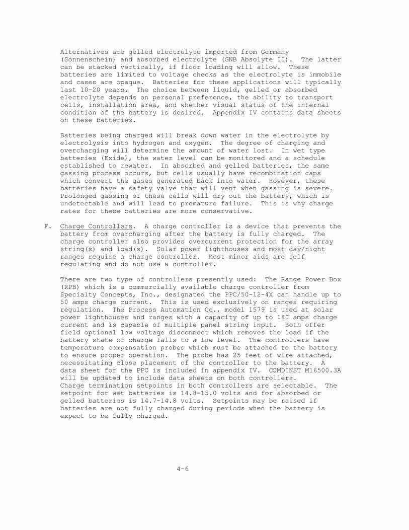
Alternatives are gelled electrolyte imported from Germany (Sonnenschein) and absorbed electrolyte (GNB Absolyte II). The latter can be stacked vertically, if floor loading will allow. These batteries are limited to voltage checks as the electrolyte is immobile and cases are opaque. Batteries for these applications will typically last 10-20 years. The choice between liquid, gelled or absorbed electrolyte depends on personal preference, the ability to transport cells, installation area, and whether visual status of the internal condition of the battery is desired. Appendix IV contains data sheets on these batteries. Batteries being charged will break down water in the electrolyte by electrolysis into hydrogen and oxygen. The degree of charging and overcharging will determine the amount of water lost. In wet type batteries (Exide), the water level can be monitored and a schedule established to rewater. In absorbed and gelled batteries, the same gassing process occurs, but cells usually have recombination caps which convert the gases generated back into water. However, these batteries have a safety valve that will vent when gassing is severe. Prolonged gassing of these cells will dry out the battery, which is undetectable and will lead to premature failure. This is why charge rates for these batteries are more conservative. F. Charge Controllers. A charge controller is a device that prevents the battery from overcharging after the battery is fully charged. The charge controller also provides overcurrent protection for the array string(s) and load(s). Solar power lighthouses and most day/night ranges require a charge controller. Most minor aids are self regulating and do not use a controller. There are two type of controllers presently used: The Range Power Box (RPB) which is a commercially available charge controller from Specialty Concepts, Inc., designated the PPC/50-12-4X can handle up to 50 amps charge current. This is used exclusively on ranges requiring regulation. The Process Automation Co., model 1579 is used at solar power lighthouses and ranges with a capacity of up to 180 amps charge current and is capable of multiple panel string input. Both offer field optional low voltage disconnect which removes the load if the battery state of charge falls to a low level. The controllers have temperature compensation probes which must be attached to the battery to ensure proper operation. The probe has 25 feet of wire attached, necessitating close placement of the controller to the battery. A data sheet for the PPC is included in appendix IV. COMDINST M16500.3A will be updated to include data sheets on both controllers. Charge termination setpoints in both controllers are selectable. The setpoint for wet batteries is 14.8-15.0 volts and for absorbed or gelled batteries is 14.7-14.8 volts. Setpoints may be raised if batteries are not fully charged during periods when the battery is expect to be fully charged. 4-6

CHAPTER 5 - LOADS Specific loads must be entered into the program in order to create a profile of daily power consumption. The following is a consolidated list of loads often found on minor and major solar powered aids: A. Lamps. Lamps that are flashed consume more than their rated current because of the cold current surge associated with tungsten filaments. The following table lists average lamp currents for typical flash rhythms (some areas are blank as either the lamp/rhythm combination is not allowed or not used). Average current for non-standard rhythms is based on the shortest ON time of the rhythm. Therefore a nonstandard rhythm with a 0.3 second flash will have the same average current as a Quick flash, however the duty cycle for the nonstandard rhythm will have to be calculated. The duty cycle is: Duty Cycle = Time ON x 100 --------------------------------- (Time ON + Time OFF) Average Lamp Current in Amperes for Rated Lamp Sizes Duty Rhythm Cycle 0.25a 0.55a 0.77a 1.0a 1.15a 1.9a 2.03a 3.0a 3.05a 50w 75w 100w 110w --------------------------------------------------------------------------------------------------------- Fixed 100 .250 .550 .770 1.00 1.15 1.90 2.03 3.00 3.05 4.17 6.25 8.33 9.17 Oc 4 75 .252 .559 .785 1.02 1.18 1.97 2.10 3.12 3.17 4.35 6.54 8.75 9.63 Iso 6 50 .252 .559 .785 1.02 1.18 1.97 2.10 3.12 3.17 4.35 6.54 8.75 9.63 Iso 2 50 .258 .578 .816 1.08 1.24 2.11 2.23 3.37 3.42 4.73 7.20 9.75 10.73 Fl(2)6 33 .258 .578 .816 1.08 1.24 2.11 2.23 3.37 3.42 4.73 7.20 9.75 10.73 Q 30 .278 .639 .916 1.24 1.42 2.55 2.76 Mo(A) 30 .262 .592 .844 1.29 2.38 3.70 IQ 18 .278 .639 .916 1.42 2.76 Fl2(5) 16 .271 .621 .894 1.38 2.62 4.15 Fl(2+1)6 15 .278 .639 .916 1.42 2.76 Fl 2.5(.3) 12 .278 .639 .916 1.42 2.76 FL2.5(1) 40 .258 .578 .816 1.08 1.24 2.11 2.23 3.37 3.42 4.73 7.20 9.75 10.73 Fl 4(.4) 10 .271 .621 .894 1.38 2.62 4.15 FL4(1) 25 .258 .578 .816 1.08 1.24 2.11 2.23 3.37 3.42 4.73 7.20 9.75 10.73 Fl 6(.6) 10 .266 .596 .859 1.31 2.45 3.81 B. VRB-25 Rotating Beacon. The VRB-25 is the standard 12 volt rotating beacon. It replaces the Amerace ESNA 190mm beacon and API FA-251-DC. The power consumption of the lamp is entered as a Nighttime only load at its rated current and 100% duty cycle as the flash rhythm is Fixed. The power consumption of the rotation motor must be entered into the program as a separate load. The motor typically operates 24 hours a 5-1

day in order to prevent the sun from focusing on the lampchanger. Power consumption is 0.10 amps, 100% duty cycle, Day/Night load. C. API Flashtube. The power consumed by the API 12-volt flashtube may be calculated as follows: The power consumption must be calculated for each flick of the flashtube: XFB-001 = 0.39 amp-secs, flash rate of 1 flash per 0.40 seconds XFB-005 = 1.34 amp-secs, flash rate of 1 flash per 0.55 seconds XFB-010 = 2.28 amp-secs, flash rate of 1 flash per 0.95 seconds XFB-015 = 2.87 amp-secs, flash rate of 1 flash per 1.20 seconds Where the flash rhythm must be equal to or longer than the flash rate listed above. Next, the power consumption for the specific rhythm must be calculated. For a 5 joule flashtube (XFB-005) with one flash every 2.5 seconds equals: Flash rate is within limitations (1 flash every 2.5 seconds; 2.5s 0.55s): 1.34 amp-secs / 2.5 secs = 0.536 amps The idle current of the flashtube must be added to this. It is 8 milliamps for all models: 0.536 amps + 0.008 amps = 0.544 amps. Enter this as a Nightly load if daylight controlled with a 100% duty cycle. Note: this calculation is different from what was previously published and existing aids using this device should be re-evaluated. D. Multiarray Controller (MAC), Solar Distribution Box (SDB) & Solar Aid Controller SAC II). The MAC and SDB consume and average of 0.025 amps, continuous. The SAC II consumes an average of 0.0025 amps, continuous. These loads are day/night loads. A typical lighthouse with a SDB and 2 SACIIs will consume 0.030 amps, 100% duty cycle, Day/Night load. The SDB will accept up to 1/0 AWG for main battery input, 6 AWG for emergency panel and battery input, and lugs sized for a number 10 stud for all loads. E. Charge Controller. The charge controller used in lighthouse and large range solarizations manufactured by Specialty Concepts and Process Automation Company consumes 0.010 amps, 100% duty cycle, Day/Night load. The controller does draw considerably more power when the mercury relays are energized, however this occurs when excess power is generated by the array in the daytime and the load does not have to be accounted for. It will accept up to 1/0 AWG wire for all inputs/outputs. 5-2

F. Range Power Box (RPB). The RPB is a commercially available charge controller manufactured by Specialty Concepts, Inc. Its is designated the PPC/50-12-4X and consumes 0.190 amps continuous, 100% duty cycle, during the Daytime. It will accept up to 6 AWG wire for all inputs/outputs. G. Range Switch Box-DC (RSB-DC). The RSB-DC is used on DC powered ranges to switch between daytime and nighttime lights. The RSB-DC consumes 0.170 amps continuous 100% duty cycle, during the Daytime. The maximum wire sizes that can be used is 1/0 AWG for input power and 10 AWG for output to each range light. H. Racon. The maximum power consumption estimates are as follows: 0.55 amps, on a 30% maximum duty cycle, 24 hours a day while transmitting, and 0.067 amps, 70% minimum, 24 hours and day while idle or listening. These estimates include continuous interrogation. The load may be simplified as 0.212 amps continuous 100% duty cycle, Day/Night load. I. Sound Signals. Power consumption for sound signals is entered as a Day/Night load during blast only; consumption during eclipse is negligible. Model Range (nmi) Current (amps) SA-850 1/4-1/2 1.25 SA-850/02 1.0 3.25 SA-850/4A 2.0 7.00 FA-232 1/4-1/2 1.80 FA-232/02 1.0 3.60 FA-232/04 2.0 9.00 Duty cycles for common rhythms are: Rhythm Time (On/Off) Duty Cycle 1 blast every 10 sec 1bl/9si 10% 1 blast every 30 sec 3bl/27si 10% 2 blasts every 60 sec 3bl/3si/3bl/51si 10% 1 blast every 15 sec 2bl/13si 13.3% 2 blasts every 30 sec 2bl/2si/2bl/24si 13.3% 2 blasts every 20 sec 2bl/2si/2bl/14si 20% For uncommon rhythms, the duty cycle may be calculated as follows: Duty Cycle = Time ON during blast (seconds) X 100 ---------------------------------------------- Time ON during blast + Time OFF during eclipse 5-3

J. Fog Detector. There are two types of fog detectors currently in use: the VM-100 and Videograph B. The latter is being phased out and will eventually be replaced by the VM-100. The VM-100 is more energy efficient than the Videograph B and solarization efforts should schedule replacement of the Videograph as part of the project. The operating currents of the Videograph B and VM-100 are 0.67 and 0.80 amperes, respectively. This is entered into the program as a continuous, 100% duty cycle, Day/Night load. All fog detectors have heaters in the projector and receiver windows to eliminate condensation in cold weather. The heaters in the Videograph B consume 2.0 amperes and turn on when the ambient outside temperature is below 50 degrees F. The heaters in the VM-100 consume 1.0 ampere and turn on when the ambient outside temperature is below 25 degrees F. Since temperature is variable, the amount of time the heaters are activated must be estimated. Enough reserve capacity is necessary to account for extremely harsh winters, however cold days are usually clear and may be considered "average insolation days". As a check, increase the duty cycle of the heater load and see if the battery SOC is acceptable using "average insolation" rather than "design insolation". Listed below are selected data sites, and the suggested duty cycle for the VM-100 heater load: +------------------------------------------------------+ | | VM-100 HEATER LOAD | |____ |________________________________________________| |Data | | Suggested | Suggested | |_____|______________________|____________|____________| |Site#| Data Site Name | Duty Cycle | Internal | |_____|______________________|____________|____________| | 1 | Portland, ME | 100% | 23 - 6 | |-----|----------------------|------------|------------| | 2 | Boston, MA | 75% | 23 - 4 | |-----|----------------------|------------|------------| | 3 | Providence, RI | 75% | 23 - 6 | |-----|----------------------|------------|------------| | 4 | Bridgeport, CT | 75% | 23 - 4 | |-----|----------------------|------------|------------| | 5 | New York, NY | 50% | 23 - 4 | |-----|----------------------|------------|------------| | 8 | Newark, NJ | 50% | 23 - 4 | |-----|----------------------|------------|------------| | 12 | Baltimore, MD | 50% | 23 - 4 | |-----|----------------------|------------|------------| | 49 | Rochester, NY | 100% | 23 - 6 | |-----|----------------------|------------|------------| | 50 | Buffalo, NY | 100% | 23 - 6 | |-----|----------------------|------------|------------| | 51 | Erie, PA | 100% | 23 - 6 | |-----|----------------------|------------|------------| | 52 | Cleveland, OH | 100% | 23 - 6 | |-----|----------------------|------------|------------| | 53 | Toledo, OH | 100% | 23 - 6 | |-----|----------------------|------------|------------| | 54 | Detroit, MI | 100% | 23 - 6 | |-----|----------------------|------------|------------| | 55 | Alpena, MI | 100% | 21 - 6 | |-----|----------------------|------------|------------| | 56 | Traverse City, MI | 100% | 23 - 6 | |-----|----------------------|------------|------------| | 57 | Muskegon, MI | 100% | 23 - 6 | |-----|----------------------|------------|------------| | 58 | Chicago, IL | 100% | 23 - 6 | |-----|----------------------|------------|------------| | 59 | Milwaukee, WI | 100% | 23 - 6 | |-----|----------------------|------------|------------| | 60 | Green Bay, WI | 100% | 21 - 6 | |-----|----------------------|------------|------------| | 61 | Sault Ste. Marie, MI | 100% | 21 - 6 | |-----|----------------------|------------|------------| | 62 | Houghton, MI | 100% | 21 - 6 | |-----|----------------------|------------|------------| | 63 | Duluth, MN | 100% | 21 - 6 | |-----|----------------------|------------|------------| | 76 | Portland, OR | 0% | N/A | |-----|----------------------|------------|------------| | 78 | Quillayute, WA | 0% | N/A |

|-----|----------------------|------------|------------| | 79 | Seattle, WA | 0% | N/A | +------------------------------------------------------+ K. Low Energy Aid Control Monitor System (LEACMS). The LEACMS is a low power version of the ACMS and can be used at solar powered lighthouses to monitor the status of the aid, including low battery alarm and main battery transfer. The LEACMS may be outfitted with an EF Johnson radio or cellular phone link to the master control unit. The power consumption of the LEACMS with the EF Johnson radio is 0.50 amps continuous, 100% duty cycle, Day/Night load, and with the cellular link is 0.75 amps continuous, 100% duty cycle, Day/Night load. 5-4

CHAPTER 6 - WIRING SIZING A. General. In conventional electrical systems (120-240 VAC), wire is sized according to its safe amperage carrying capacity know as "ampacity". A voltage drop of 2-3 volts in these systems is acceptable. Since voltage drop is based on wire size and current, not voltage, if these practices are carried over to low voltage systems, the resultant voltage drop would cause inadequate charging of the battery and low voltage to the aids to navigation. B. Acceptable Voltage Drops. The acceptable voltage drop for 12 volt solar power aids to navigation is 0.75 volts in the charging system and 0.35 volts for the load(s). The "charging system" is considered the wire run from the solar panels to the battery, and the "load(s)" is considered the wire run from the battery to the device (CG-181, FA-232, etc.). These voltage drops are maximums and efforts to reduce these values is encouraged. The voltage drop for minor aids remains at 0.10 volts for the load. C. Wire Sizes and Typical Voltage Drops. The following are common wire sizes and their calculated voltage drop for a 1 amp current at 1000 feet: Wire Size K* --------------------------- 12 AWG 3.960 volts 10 AWG 2.480 volts 8 AWG 1.556 volts 6 AWG 0.982 volts 4 AWG 0.616 volts 2 AWG 0.388 volts 1/0 AWG 0.244 volts 2/0 AWG 0.193 volts 3/0 AWG 0.153 volts 4/0 AWG 0.122 volts *These K values are based on National Electric Code (NEC) recommendations for uncoated, stranded copper conductors. These values are conservative. Resistance values from the cable supplier may be used to calculate new K values. To calculate K: K = Wire Resistance (ohms) per 1000 feet x 2 Therefore, the voltage drop for a given wire run is: Voltage Drop (V1324 Drop & TA &) = K x A x D --------- 1000 Where: A is the current in amperes D is the one way distance in feet 6-1
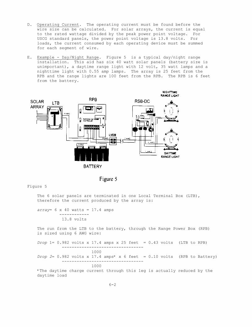
D. Operating Current. The operating current must be found before the wire size can be calculated. For solar arrays, the current is equal to the rated wattage divided by the peak power point voltage. For USCG standard panels, the power point voltage is 13.8 volts. For loads, the current consumed by each operating device must be summed for each segment of wire. E. Example - Day/Night Range. Figure 5 is a typical day/night range installation. This aid has six 40 watt solar panels (battery size is unimportant), a daytime range light with 12 volt, 35 watt lamps and a nighttime light with 0.55 amp lamps. The array is 25 feet from the RPB and the range lights are 100 feet from the RPB. The RPB is 6 feet from the battery.
Figure 5 The 6 solar panels are terminated in one Local Terminal Box (LTB), therefore the current produced by the array is: array= 6 x 40 watts = 17.4 amps ------------ 13.8 volts The run from the LTB to the battery, through the Range Power Box (RPB) is sized using 6 AWG wire: Drop 1= 0.982 volts x 17.4 amps x 25 feet = 0.43 volts (LTB to RPB) --------------------------------- 1000 Drop 2= 0.982 volts x 17.4 amps* x 6 feet = 0.10 volts (RPB to Battery) --------------------------------- 1000 *The daytime charge current through this leg is actually reduced by the daytime load 6-2

CHAPTER 8 - SOLAR SIZING TABLES A. Discussion. Solar sizing tables are provided as a quick reference for buoys and fixed structures using simple rhythms and power systems. The tables do not cover installations with multiple loads (lantern & sound signal) nor multiple solar panel arrays. Sizings are limited to 35 watts and 300 amp-hours for structures, and 35 watt and 500 amp-hours for buoys. Aids with power requirements that exceed these limits should perform a design run to determine optimum system sizings; buoy installations in excess of this limit may benefit from using dual or quadruple vertically mounted solar panels. The tables are revised to reflect the new data provided by NREL. In many cases, the designs are more conservative compared to the old tables and increases in panel and battery size are common. To alleviate this problem, tables are provided for all 92 data sites as the old sizing tables picked the worst one or two data sites in the district and based all calculations on these sites. To use the tables, find the data site nearest to the aid and select the appropriate row containing the flasher rhythm and aid type (B-Buoy, S-Structure). Next, find the column containing the lamp required for the aid. The intersection of the row and column lists the required power system. A 10/100 refers to a 10 watt solar panel and one minor aid solar battery (100 amp-hours nominal capacity). If the aid is between two data sites, look up the power system combination for both sites and use the larger of the panel/battery combinations. If the intersection is blank or marked "N/A", either the combination is normally not used or the system sizing exceeds the limitations detailed above. Calculate the system sizing using the solar design program or the solar vertical program (dual and quad mounts on buoys). Also, note that the sizing tables are intended for wet or liquid electrolyte batteries (Delco, Exide). Use of absorbed (Sunlyte) or gelled (Sonnenschein, Johnson Controls, Deka) batteries may require more units to ensure overcharge protection. As a general rule, a minimum of one, two and three batteries of these types are needed when using 10, 20 and 35 watt panels, respectively, or the combination cited in the table, whichever is larger. 8-1

SOLAR SIZING TABLE 1 & 2
8-2

SOLAR SIZING TABLE 3 & 4
8-3

SOLAR SIZING TABLE 5 & 6
8-4

SOLAR SIZING TABLE 7 & 8
8-5

SOLAR SIZING TABLE 9 & 10
8-6

SOLAR SIZING TABLE 11 & 12
8-7

SOLAR SIZING TABLE 13 & 14
8-8

SOLAR SIZING TABLE 15 & 16
8-9

SOLAR SIZING TABLE 17 & 18
8-10

SOLAR SIZING TABLE 19 & 20
8-11

SOLAR SIZING TABLE 21 & 22
8-12

SOLAR SIZING TABLE 23 & 24
8-13

SOLAR SIZING TABLE 25 & 26
8-14

SOLAR SIZING TABLE 27 & 28
8-15

SOLAR SIZING TABLE 29 & 30
8-16

SOLAR SIZING TABLE 31 & 32
8-17

SOLAR SIZING TABLE 33 & 34
8-18

SOLAR SIZING TABLE 35 & 36
8-19

SOLAR SIZING TABLE 37 & 38
8-20

SOLAR SIZING TABLE 39 & 40
8-21

SOLAR SIZING TABLE 41 & 42
8-22

SOLAR SIZING TABLE 43 & 44
8-23

SOLAR SIZING TABLE 45 & 46
8-24

SOLAR SIZING TABLE 47 & 48
8-25

SOLAR SIZING TABLE 49 & 50
8-26

SOLAR SIZING TABLE 51 & 52
8-27

SOLAR SIZING TABLE 53 & 54
8-28

SOLAR SIZING TABLE 55 & 56
8-29

SOLAR SIZING TABLE 57 & 58
8-30

SOLAR SIZING TABLE 59 & 60
8-31

SOLAR SIZING TABLE 61 & 62
8-32

SOLAR SIZING TABLE 63 & 64
8-33

SOLAR SIZING TABLE 65 & 66
8-34

SOLAR SIZING TABLE 67 & 68
8-35

SOLAR SIZING TABLE 69 & 70
8-36

SOLAR SIZING TABLE 71 & 72
8-37

SOLAR SIZING TABLE 73 & 74
8-38

SOLAR SIZING TABLE 75 & 76
8-39

SOLAR SIZING TABLE 77 & 78
8-40

SOLAR SIZING TABLE 79 & 80
8-41

SOALR SIZING PANEL 81 & 82
8-42

SOLAR SIZING TABLE 83 & 84
8-43

SOLAR SIZING TABLE 85 & 86
8-44

SOLAR SIZING TABLE 87 & 88
8-45

SOLAR SIZING TABLE 89 & 90
8-46

SOLAR SIZING TABLE 91 & 92
8-47

Appendix I - Sample Calculations

Appendix I - Sample Calculations Cont'd.

Appendix II - Addendum for Solar Vertical Program The solar vertical program is used exclusively for buoys with single, dual or quad mounted solar panels. The program will only evaluate flat or vertically mounted solar panels. This program does not have an input for tilt angles and evaluation of the dual panel mount (15 degree tilt), tripod mount (60 degrees) and any fixed structure requires use of the solar design program. Data entry is the same as the solar design program with the exception of the panel tilt (no entry) and array size. The program has three suggested array sizes: Horizontal Panel, 4 Vertical Panels and 2 Vertical Panels. The program suggests panel sizes for all three combinations. If 40+ is suggested, then that combination alone may not satisfy the design constraints of 65-70 percent minimum state of charge. If 40+ exists for all suggestions, then combinations of two suggestions (horizontal and vertical panels), doubling of the quad array (8 panels; enter 80 watts) or inclusion of a Wave Turbine Generator (WTG) may provide satisfactory results. Once the array type is chosen, enter solar panel wattage into the appropriate block. If more than one block is filled, then the buoy must be outfitted with both combinations (i.e., one horizontal panel and 4 quad mounted panels). The contribution by a WTG can be approximated by entering the WTG output as 0.5 amp "additional input amperage" in block M48 of the spreadsheet. This contribution of 12 amp-hours per day is realistic for sites with continuous wave action. WTGs should only be used as a last resort to adding additional solar panels as they are costly and maintenance intensive. This program can not evaluate installation of solar panels in radar reflectors of buoys. Shadowing of the panel(s) by the lantern ring and adjacent walls of the reflector will reduce output of the array. Installation of solar panels in this area is not recommended.

Solar Vertical Program Sample Calculation

Oct 97 Appendix III - Battery Acquisition and Application Data The following is a list of batteries recommended by Commandant (G-SEC-2) for use in solar powered aids to navigation. Batteries listed here have shown, through manufacturer's literature, testing or field experience, to perform well in our unique environment. Batteries are categorized as either "qualified" or "conditionally qualified". "Qualified" refers to batteries that have been tested and perform well in the field. "Conditionally qualified" are batteries that are new technology being evaluated, or batteries that have limitations placed on them. New batteries that are conditionally qualified should not be placed in critical aids or in aids at the outskirts of your area of responsibility. All batteries are 12 volts, 100 ampere-hours (nominal) and intended for use in all solar powered minor aids, unless otherwise specified. Please call the vendors for a current price quote and shipping costs (if applicable). Delco 2000, Delco S2000 Features: 12 volt, liquid electrolyte, lead calcium grid, maintenance-free, not sealed. Available from the factory in quantities of 54 (Delco 2000) or lesser quantities from local wholesalers (Delco S2000). Price $63.50 to $68.00. Price quoted from factory is delivered to destination by truck freight. Price quoted from wholesaler is delivered to destination by Mobile Battery Truck (MBT). Status: Qualified Ordering Addresses: Factory: Delco Remy P.O. Box 2439 Anderson, IN 46018 (317) 579-3591 Wholesalers: Batteries, Inc. 4788 Lake Mirror Place Forest Park, GA 30050 (404) 361-6260 Attn: Randy Dunn Delcoline, Inc., Automotive Parts and Warehouser and Exporter 4631 Tanglewood Drive 1

Oct 97 Hyattsville, MD 20781 (301) 864-4455 Attn: Kambiz Majidi Diesel Service Unit P.O. Box 3486 Portland, OR 97208 (800) 556-4998 [(800) 452-9179 in OR] Attn: Larry Clay GNB Sunlyte 12-5000 Features: 12 volt, absorbed electrolyte, lead calcium grid, maintenance free, handle, sealed. Price: $96.00 plus shipping (must be prepaid). Status: Conditionally qualified (not recommended in hot climates) Ordering address: See below. GNB Absolyte IIP Features: 2-volt, absorbed electrolyte, lead calcium grid, sealed, maintenance free, used in large lighthouse and range power systems. Capacities from 340 AH to 5700 AH. Price: $144.00 - $1585.00 per cell plus shipping (must be prepaid). Status: Conditionally qualified (not recommended in hot climates) Ordering address: GNB Battery Technologies 829 Parkview Blvd. Lombard, IL 60148-3249 (708) 629-5200 Ask for Government sales Exide EJ and FHGS series Features: 2-volt, liquid electrolyte, tubular lead calcium low antimony grid, requires annual watering, not sealed, used in large lighthouse and range power systems. Capacities from 390 AH to 2915 AH. Price: $307.50 to $1468.50 per cell delivered in 48 states (6 cells must be ordered, and 1.300 specific gravity must be specified). General Services Administration schedule pending; call for availability. Status: Qualified (must be used on stable platform) 2

Oct 97 Ordering address: Yuasa-Exide, Inc. 9055 Guilford Road Columbia, MD 21046-1879 (410) 381-8500 Exide HC-31 Features: 12 volt, liquid electrolyte, lead calcium grid, maintenance free, handle, not sealed. Price: $54.00 plus shipping (must be prepaid). Status: Conditionally qualified (new vendor) Ordering address: (note: this is a different division and should not be confused with Yuasa-Exide). Exide Corporation 817 Manufacturers Drive Westland, MI 48185 (800) 323-2914 Sonnenschein Dryfit A 600 Solar Features: 2-volt, gelled electrolyte, lead calcium grid, sealed, maintenance free, used in large lighthouse and range power systems. Capacities from 360 AH to 3500 AH. Price: $144.00 - $893.00 per cell plus shipping (must be prepaid). Status: Conditionally qualified (new vendor in US, established in Europe) Ordering address: Exide Corporation - International Gel Product Sales 645 Penn Street Reading, PA 19601 (610) 378-0500 Peter Grimes Johnson Controls Dynasty GC12V100B Features: 12 volt, gelled electrolyte, lead calcium grid, handle, maintenace free, sealed, same as Solar Electric Specialties 12SC90B which is no longer available. Price: $112.00 to $150.00, depending on quantity, plus shipping (must be prepaid). 3

Oct 97 Status: Conditionally qualified (new vendor) Ordering address: Contact Commandant (G-SEC-2) for nearest distributor Deka Solar 8G30H Features: 12 volt, gelled electrolyte, lead calcium grid, maintenance free, handle, sealed. Price: $140.00 plus shipping (must be prepaid). Status: Conditionally qualified (new vendor) Ordering address: East Penn Manufacturing Co. Lyon Station, PA (215) 682-6361 4

DESCRIPTION OF COAST GUARD ELECTRONIC EQUIPMENT

DESCIPTION OF COAST GUARD ELECTRONIC EQUIPMENT

DESCRIPTION OF COAST GUARD ELECTRONIC EQUIPMENT

DESCRIPTION OF COAST GUARD ELECTRONIC EQUIPMENT

DESCRIPTION OF COAST GUARD ELECTRONIC EQUIPMENT

DESCRIPTION OF COAST GUARD ELECTRONIC EQUIPMENT

SIEMENS M65 Self regulating solar electric module
RATED POWER 43 WATTS. With 30 cells in series, the high efficiency Siemens M65 is a 43 watt, self regulating solar electric module. Self regulation eliminates the need for seperate charge control devices, resulting in a simple, reliable and economical power generating system. The M65 module regulates its electrical output to the needs of the battery. As the battery approaches full charge, it decreases its typical current charging rate of nearly 3 amps to less than 1/2 amp. Utilizing the highest standard of construction, the M65 module is able to withstand some of the harshest environments in the world and continue to perform efficiently. Siemens solar electric modules are tested to meet or exceed industry standards, and even more rigorous Siemens quality and performance requirements. 10 YEAR WARRANTY. The Siemens M65 solar electric module carries a 10-year limited warranty on power output and is listed by Underwriters Laboratories (UL), an independent, not for profit organization, testing for public safety. Siemens solar electric module features: Silent operation Sunlight as fuel High power density Easy installation Rugged, durable construction Simple, reliable operation East to expand systems Low maintenance No moving parts to wear out No environmental pollutants

M65 Self regulating solar electric module

SIEMENS M75 High efficiency solar electric module (used to charge emergency Nicad batteries at solar power lighthouses)
RATED POWER 48 WATTS. The Siemens M75 is a 48 watt solar electric module with 33 high efficiency single crystal solar cells in series. It represents the optimum module configuration for battery charging in all but the very hotttest of climates. Maintaining the quality, features and construction that are industry standards, the M75 solar module can withstand some of the world's harshest environments and continue to perform efficiently. It is an effficient, reliable and durable power module, suitable for a wide variety of applications. Siemens solar electric modules are tested to meet or exceed industry standards, and even more rigorous Siemens quality and performance requirements. 10 YEAR WARRANTY. Designed for easy installation, the Siemens M75 solar module is sold with comprehensive installation and operating instructions. It carries a 10-year limited warranty on power output and is listed by Underwriters Laboratories (UL), an independent, not for profit organization, testing for public safety. Siemens solar electric module features: Silent operation Sunlight as fuel High power density Easy installation Rugged, durable construction Simple, reliable operation East to expand systems Low maintenance No moving parts to wear out No environmental pollutants

M75 High efficiency solar electric module

SIEMENS SGM Standard Ground Mount
Siemens Standard Ground Mounts are available in two sizes: Model SGM-4 for 2 to 4 module systems and Model SGM-8 fot up to 8 module systems. Easy to install. Both models consist of two parallel channels with adjustable support legs and feet. (Packaged with detailed installation instructions and all necessary mounting hardware. Rugged. Engineered for exceptional structural strength. Siemens Standard Ground Mounts are built to withstand wind speeds of up to 125 miles per hour. Lightweight. Channels and support legs are fabricated from extruded Type 6061-T6 aluminum alloy; mounting feet are made of galvanized steel. Environmentally Sound. Built to withstand environmental forces including wind, rain, snow, ice, blowing sand and solar radiation. Corrosion resistant. Channels and support legs are anodized in accordance with architectural specification MIL A 8625 Type 2 Class 1 with nickel acetate seal. Durable. Materials have been chosen for their durability and compatability with other materials in the array. Flexible. Designed for optimum flexibilty in tilt angles (angle from the horizontal plane to the back of the modules). Siemens Standard Ground Mounts are adjustable in nominal 5 increments from 15 to 65.

SGM Standard Ground Mount

AGV Photvoltaic Battery Delco 2000 Maintenance-Free Battery

12-5000X 6-Cell, 12 Volt Valve Regulated Lead Acid Battery

Tubular Stationary Batteries for Shallow Cycle Solar

Specifications Cell Dimensions - Weights

Ironclad-Tubular Type EJ General Purpose

Capacities - Dimensions - Weights

ABSOLYTE IIP Batteries
THE WORLD LEADER IN SEALED BATTERY POWER Proven field experience since 1983. The Absolyte IIP represents the third generation of the Absolyte product line. Without an increase in size, it offers 15% more capacity than its predecessor, the Absolyte II. Patented MFX positive grid alloy* provides long-life. This propriety alloy gives Absolyte IIP superior cycling performance and excellent float characteristics: 1200 cycles to 80% D.O.D. and a twenty year life in float service @ 25C (77 F). This alloy also has low gassing characteristics and is designed to allow for deep discharge recovery. Absorbed glass mat seperators for efficient operation. The positive and negative plates are seperated by a highly porous fiberglas mat which functions as the electrolyte retainer and provides the highest oxygen recombination efficiency. In addition, the low resistance of the glass mat improves high rate discharge performance. Reduced installation and maintenance time. The Absolyte IIP cells are housed in protective, modular steel trays designed for easy installation and balanced thermal management. Modules may be stacked horizontally (preferred) or installed vertically (50A, 90A only). When stacked horizontally, the standard Absolyte IIP is qualified for use in U.B.C. Seismic Zone IV installations. With the sealed design, maintenance is also kept to a minimum. No water additions or scheduled equalization charges are required. Periodic visual inspections, voltage readings and connection retorqing is all that is required. Highest reliability is assured by GNB's quality program. Cell covers are hermetically sealed using a special GNB double-sealing process. Post seals are formed by fusing the lead bushing to the post with a robotic welder. Cells are checked by an automated, ultra-sensitive helium leak detection unit prior to the controlled electrolyte "fill by weight" process. These steps virtually eliminate any potential for leaking cells. Finally, all cells are capacity tested prior to shipment to verify attainment of specified ratings. APPLICATIONS The Absolyte IIP batteries are ideal for numerous applications including: Telecommunications Uninterruptible Power Systems Switchgear and Control

Railroad Signal and Communication Photovoltaics Marine Alternative Energy Systems ADDED FEATURES & BENEFITS Does not require a seperate Battery room Transparent, flame retardant module cover Recombination efficiency greater than 99% Freezing tolerant Deep discharge recovery Accepts high rate charge Meets U.B.C. Seismic Zone IV requirements Simple cell replacement capability CELL SPECIFICATIONS Container and Cover - Polyproylene is standard. Flame retardant, UL94 V-0/28% L.O.I. is optional. Separators - Spun glass, microporous matrix. Safety Vent - 400mb (6psi) nominal, self-resealing (patented). Teriminals - Integral solid copper core. Positive Plate - Patented MFX grid alloy.* Negative Plate - Lead calcium grid alloy. Life - 20 years float @ 25 C (77F). Self Discharge - 0.5 to 1% per week maximum @ 25 C (77F). Float Voltage - 2.23 to 2.27 VPC (2.25 recommended) @ 25 C (77F). ASSEMBLY CONFIGURATIONS Horizontal Stack Assembly (Preferred). Depth is overall, including module cover assembly. Add 102mm (4") for bottom I-beam supports to determine total height (width) of assembled horizontal stack.
Vertical Assembly, Side-by-side. Height is overall, including module cover assembly. Add 51mm (2") for bottom channel support to determine final height.

ABSOLYTE IIP Batteries Absolyte IIP Module Weights and Dimensions

dryfit A 600 solar


PPC/50 - Photovoltaic Charge Control SPECIALTY CONCEPTS,INC. PHOTOVOLTAIC CHARGE CONTROLLER
The PHOTOVOLTAIC POWER CONTROL (PPC/50) is a versatile, industrial quality controller for the efficient use of the photovoltaic energy and the protection of expensive batteries. It is available for 12, 24, 36 and 48 volt negative ground systems. Models are available for 50 amps of charge current. The PPC/50 consists of a series-relay battery charge regulator with low-voltage load dissconnect, battery, array and load circuit breakers, system status lights and digital metering. The lights indicate "CHARGING" and "LOW-VOLTAGE LOAD DISCONNECT" conditions and the digital meter monitors battery voltage, charging and load current. A provision is made for monitoring an external shunt. The PPC/50 is housed in a sealed indoor enclosure and has a terminal block for up to 6 guage wire. FEATURES CHARGE REGULATION 50 amp charge current, 12, 24, 36 or 48 volt Two-step, series charging, 12, 24 v Single step, series charging, 36, 48 v Adjustable charging set-points Plug-in temperature compensation LOW-VOLTAGE LOAD DISCONNECT (LVD) 30 amp LVD, 12 volt 20 amp LVD, 24 volt 15 amp LVD, 36 and 48 volt Adjustable charging set-points Plug-in temperature compensation DESIGN FEATURES Maximum array usage Over-current protection and manual disconnects - battery, array and load circuit breakers Reverse polarity protection Reverse leakage protection Lightning protection Input noise suppression Remote battery voltage sense MONITORING Digital volt/amp meter

External shunt metering Charging Light Load disconnect light MOUNTING Indoor wall mount enclosure Outdoor enclosure (optional) OPERATION (12,24 volt units) Note: The operation of the 36 or 48 volt unit is identical with the exception that no float unit is included. CHARGE REGULATION - The PPC/50 features two charging steps to effectively charge the batteries and protect them from over-charge damage. The PPC/50 monitors the battery and array voltage, using a relay to control the charging. STEP 1 - FULL CHARGE: At sunrise, the rising array voltage will energize the charging relay and initiate a full charge mode, as indicated by the "CHARGE MODE" light. All available current from the array will pass through to the batteries and raise the battery voltage until the battery reaches the full charge termination threshold. STEP 2-FLOAT CHARGE: When the battery reaches the full charge termination threshold, the full-charge mode ends and the "CHARGE MODE" light goes out. The PPC/50 resumes charging at a reduced charging rate. As the battery approaches the float voltage, the current will taper off, eventually reaching the battery's maintenance current. LOW-VOLTAGE DISCONNECT- The low-voltage disconnect (LVD) of the PPC/50 prevents damage from deep-discharge of the batteries by automatically disconnecting the loads. The disconnect threshold is load current compensated, and has a time delay to prevent false disconnects. When disconnect occurs, the load relay is energized and opens, and the "LOAD DISCONNECT" light will indicate that the loads have been disconnected. Normal battery charging will continue. At the reconnect threshold the loads will automatically be reconnected and the light will go off. The LVD function has a reset/disable switch and user adjustable set-points. DESIGN FEATURES- The PPC/50 has many superior design features that contribute to the controller's efficiency and reliability. This controller provides maximum utilization of the array during hours of charging by reconnecting the array for direct charging as soon as the battery drops below a full charge set-point. Over-current protection is provided in the form of circuit breakers. A timing circuit will disconnect the array at night, to prevent reverse current leakage. The control circuit is protected from reverse polarity connection on all inputs, and has MOV lightning protection. Input noise suppression filters out most of the spikes and interference to reduce false switching. Remote battery sense terminals allow accurate monitoring of battery voltage. OPTIONAL ENCLOSURES 3R - Outdoor, moderate protection 4X - Outdoor, maximum protection

Photovoltaic Power Control