Embed Size (px)
Citation preview
IBM BladeCenterManagement Module
BladeCenter T Management Module
Advanced Management Module
BladeCenter T Advanced Management Module
Command-Line Interface Reference Guide
���


IBM BladeCenterManagement Module
BladeCenter T Management Module
Advanced Management Module
BladeCenter T Advanced Management Module
Command-Line Interface Reference Guide
���

Note: Before using this information and the product it supports, read the general information in Appendix A, “Getting help and
technical assistance,” on page 107 and Appendix B, “Notices,” on page 109.
Fifth Edition (January 2006)
© Copyright International Business Machines Corporation 2006. All rights reserved.
US Government Users Restricted Rights – Use, duplication or disclosure restricted by GSA ADP Schedule Contract
with IBM Corp.

Contents
Chapter 1. Introduction . . . . . . . . . . . . . . . . . . . . . . 1
Before you begin . . . . . . . . . . . . . . . . . . . . . . . . 2
Chapter 2. Using the command-line interface . . . . . . . . . . . . . 3
Command-line interface guidelines . . . . . . . . . . . . . . . . . . 3
Selecting the command target . . . . . . . . . . . . . . . . . . . . 4
Commands and user authority . . . . . . . . . . . . . . . . . . . . 5
Cabling the management module . . . . . . . . . . . . . . . . . . 9
Networked connection . . . . . . . . . . . . . . . . . . . . . 10
Direct connection . . . . . . . . . . . . . . . . . . . . . . . 10
Serial connection (advanced management module only) . . . . . . . . . 10
Starting the command-line interface . . . . . . . . . . . . . . . . . 10
Telnet connection . . . . . . . . . . . . . . . . . . . . . . . 11
Serial connection . . . . . . . . . . . . . . . . . . . . . . . 11
Secure Shell (SSH) connection . . . . . . . . . . . . . . . . . . 12
BladeCenter unit configuration . . . . . . . . . . . . . . . . . . . 12
Configuring the management module . . . . . . . . . . . . . . . . . 13
Starting an SOL session . . . . . . . . . . . . . . . . . . . . . 14
Ending an SOL session . . . . . . . . . . . . . . . . . . . . . . 15
Chapter 3. Command reference . . . . . . . . . . . . . . . . . . 17
Built-in commands . . . . . . . . . . . . . . . . . . . . . . . 18
env (environment) command . . . . . . . . . . . . . . . . . . . 18
help command . . . . . . . . . . . . . . . . . . . . . . . . 20
history command . . . . . . . . . . . . . . . . . . . . . . . 21
list (system physical configuration) command . . . . . . . . . . . . . 22
Common commands . . . . . . . . . . . . . . . . . . . . . . . 23
health command . . . . . . . . . . . . . . . . . . . . . . . 23
identify (location LED) command . . . . . . . . . . . . . . . . . 25
info (configuration information) command . . . . . . . . . . . . . . 26
update (update firmware) command . . . . . . . . . . . . . . . . 27
Configuration commands . . . . . . . . . . . . . . . . . . . . . 30
alertentries command . . . . . . . . . . . . . . . . . . . . . 30
clear command . . . . . . . . . . . . . . . . . . . . . . . . 36
dhcpinfo command . . . . . . . . . . . . . . . . . . . . . . 37
displaysd command (advanced management module only) . . . . . . . . 38
dns command . . . . . . . . . . . . . . . . . . . . . . . . 38
ifconfig command . . . . . . . . . . . . . . . . . . . . . . . 40
portcfg command (advanced management module only) . . . . . . . . . 44
read command (advanced management module only) . . . . . . . . . 45
service command (advanced management module only) . . . . . . . . 45
smtp command . . . . . . . . . . . . . . . . . . . . . . . . 46
snmp command . . . . . . . . . . . . . . . . . . . . . . . 47
sol (serial over LAN) command . . . . . . . . . . . . . . . . . . 52
tcpcmdmode command . . . . . . . . . . . . . . . . . . . . . 55
telnetcfg (Telnet configuration) command . . . . . . . . . . . . . . 56
uplink (management module failover) command . . . . . . . . . . . . 57
users (management-module users) command . . . . . . . . . . . . 59
write command (advanced management module only) . . . . . . . . . 69
Event-log commands . . . . . . . . . . . . . . . . . . . . . . . 69
clearlog command . . . . . . . . . . . . . . . . . . . . . . . 69
displaylog command . . . . . . . . . . . . . . . . . . . . . . 70
Power-control commands . . . . . . . . . . . . . . . . . . . . . 71
© Copyright IBM Corp. 2006 iii

boot command . . . . . . . . . . . . . . . . . . . . . . . . 71
fuelg command . . . . . . . . . . . . . . . . . . . . . . . . 72
power command . . . . . . . . . . . . . . . . . . . . . . . 75
reset command . . . . . . . . . . . . . . . . . . . . . . . . 77
Session commands . . . . . . . . . . . . . . . . . . . . . . . 79
console command . . . . . . . . . . . . . . . . . . . . . . . 79
exit command . . . . . . . . . . . . . . . . . . . . . . . . 80
System management commands (for BladeCenter T only) . . . . . . . . . 81
alarm command . . . . . . . . . . . . . . . . . . . . . . . 81
Chapter 4. Error messages . . . . . . . . . . . . . . . . . . . . 87
Common errors . . . . . . . . . . . . . . . . . . . . . . . . . 88
alarm command errors . . . . . . . . . . . . . . . . . . . . . . 89
alertentries command errors . . . . . . . . . . . . . . . . . . . . 90
boot command errors . . . . . . . . . . . . . . . . . . . . . . 90
clear command errors . . . . . . . . . . . . . . . . . . . . . . 90
clearlog command errors . . . . . . . . . . . . . . . . . . . . . 91
console command errors . . . . . . . . . . . . . . . . . . . . . 91
dhcpinfo command errors . . . . . . . . . . . . . . . . . . . . . 91
displaylog command errors . . . . . . . . . . . . . . . . . . . . 91
displaysd command errors . . . . . . . . . . . . . . . . . . . . . 92
dns command errors . . . . . . . . . . . . . . . . . . . . . . . 92
fuelg command errors . . . . . . . . . . . . . . . . . . . . . . 92
health command errors . . . . . . . . . . . . . . . . . . . . . . 93
identify command errors . . . . . . . . . . . . . . . . . . . . . 93
ifconfig command errors . . . . . . . . . . . . . . . . . . . . . 93
info command errors . . . . . . . . . . . . . . . . . . . . . . . 95
list command errors . . . . . . . . . . . . . . . . . . . . . . . 96
power command errors . . . . . . . . . . . . . . . . . . . . . . 96
portcfg command errors . . . . . . . . . . . . . . . . . . . . . 96
read command errors . . . . . . . . . . . . . . . . . . . . . . 96
reset command errors . . . . . . . . . . . . . . . . . . . . . . 97
service command errors . . . . . . . . . . . . . . . . . . . . . 97
smtp command errors . . . . . . . . . . . . . . . . . . . . . . 97
snmp command errors . . . . . . . . . . . . . . . . . . . . . . 97
sol command errors . . . . . . . . . . . . . . . . . . . . . . . 98
tcpcmdmode command errors . . . . . . . . . . . . . . . . . . . 99
telnetcfg command errors . . . . . . . . . . . . . . . . . . . . 100
update command errors . . . . . . . . . . . . . . . . . . . . . 100
uplink command errors . . . . . . . . . . . . . . . . . . . . . 102
users command errors . . . . . . . . . . . . . . . . . . . . . 102
write command errors . . . . . . . . . . . . . . . . . . . . . . 105
Appendix A. Getting help and technical assistance . . . . . . . . . . 107
Before you call . . . . . . . . . . . . . . . . . . . . . . . . 107
Using the documentation . . . . . . . . . . . . . . . . . . . . . 107
Getting help and information from the World Wide Web . . . . . . . . . 107
Software service and support . . . . . . . . . . . . . . . . . . . 108
Hardware service and support . . . . . . . . . . . . . . . . . . . 108
Appendix B. Notices . . . . . . . . . . . . . . . . . . . . . . 109
Edition notice . . . . . . . . . . . . . . . . . . . . . . . . . 109
Trademarks . . . . . . . . . . . . . . . . . . . . . . . . . . 110
Important notes . . . . . . . . . . . . . . . . . . . . . . . . 110
Product recycling and disposal . . . . . . . . . . . . . . . . . . . 111
Battery return program . . . . . . . . . . . . . . . . . . . . . . 112
iv IBM BladeCenter: Management Module Command-Line Interface Reference Guide

Electronic emission notices . . . . . . . . . . . . . . . . . . . . 113
Federal Communications Commission (FCC) statement . . . . . . . . 113
Industry Canada Class A emission compliance statement . . . . . . . . 113
Australia and New Zealand Class A statement . . . . . . . . . . . . 113
United Kingdom telecommunications safety requirement . . . . . . . . 113
European Union EMC Directive conformance statement . . . . . . . . 113
Taiwanese Class A warning statement . . . . . . . . . . . . . . . 114
Chinese Class A warning statement . . . . . . . . . . . . . . . . 114
Japanese Voluntary Control Council for Interference (VCCI) statement 114
Index . . . . . . . . . . . . . . . . . . . . . . . . . . . . 115
Contents v

vi IBM BladeCenter: Management Module Command-Line Interface Reference Guide
Chapter 1. Introduction
The IBM® BladeCenter® management-module command-line interface (CLI)
provides direct access to BladeCenter management functions as an alternative to
using the Web-based user interface. Using the command-line interface, you can
issue commands to control the power and configuration of the management module
and other components that are in a BladeCenter unit.
All IBM BladeCenter units are referred to throughout this document as the
BladeCenter unit. All management modules are referred to throughout this
document as the management module. Unless otherwise noted, all commands can
be run on all management module and BladeCenter unit types.
The command-line interface also provides access to the text-console command
prompt on each blade server through a serial over LAN (SOL) connection. See the
IBM BladeCenter Serial Over LAN Setup Guide for information about SOL and
setup instructions.
You access the management-module CLI by establishing a Telnet connection to the
IP address of the management module or through a Secure Shell (SSH)
connection. You can initiate connections from the client computer using standard
remote communication software; no special programs are required. Users are
authenticated by the management module before they can issue commands. You
enter commands one at a time; however, you can use command scripting to enter
multiple commands. The interface does not support keyboard shortcuts, except for
the special key sequence (pressing “Esc” then “(”) that terminates an SOL session.
The most recent versions of all BladeCenter documentation are available from the
IBM Web site at http://www.ibm.com/support/.
© Copyright IBM Corp. 2006 1

Before you begin
Hardware and software required for the command-line interface are as follows:
Hardware:
No special hardware is required to use the management-module
command-line interface.
To use the SOL feature, an Ethernet I/O module that supports SOL must be
installed in I/O-module bay 1. You can use the console command to control
a blade server through SOL only on blade server types that support SOL
functionality and have an integrated system management processor
firmware level of version 1.00 or later. See the IBM BladeCenter Serial Over
LAN Setup Guide for information.
Firmware:
Make sure you are using the latest versions of device drivers, firmware, and
BIOS code for your blade server, management module, and other
BladeCenter components. Go to the IBM Support Web site,
http://www.ibm.com/support/ for the latest information about upgrading the
device drivers, firmware, and BIOS code for BladeCenter components. The
latest instructions are in the documentation that comes with the updates.
The management-module CLI is supported by BladeCenter
management-module firmware level version 1.08 or later. All versions of
BladeCenter T management-module firmware support the command-line
interface. The SOL feature has additional firmware requirements. See the
IBM BladeCenter Serial Over LAN Setup Guide for information.
2 IBM BladeCenter: Management Module Command-Line Interface Reference Guide

Chapter 2. Using the command-line interface
The IBM management-module command-line interface (CLI) provides a convenient
method for entering commands that manage and monitor BladeCenter components.
This chapter contains the following information about using the command-line
interface:
v “Command-line interface guidelines”
v “Selecting the command target” on page 4
v “Commands and user authority” on page 5
v “Cabling the management module” on page 9
v “Starting the command-line interface” on page 10
v “BladeCenter unit configuration” on page 12
v “Configuring the management module” on page 13
v “Starting an SOL session” on page 14
v “Ending an SOL session” on page 15
See Chapter 3, “Command reference,” on page 17 for detailed information about
commands that are used to monitor and control BladeCenter components.
Command-line interface error messages are in Chapter 4, “Error messages,” on
page 87. See the IBM BladeCenter Serial Over LAN Setup Guide for SOL setup
instructions and the documentation for your operating system for information about
commands you can enter through an SOL connection.
Command-line interface guidelines
All commands have the following basic structure:
command -option parameter
Some commands do not require options and some command options do not require
parameters. You can add multiple options to a command on one line to avoid
repeating the same command. Options that display a value and options that set a
value must not be used together in the same command. Some examples of valid
command option syntax are:
v command
v command -option_set
v command -option_set parameter
v command -option1_set parameter -option2_set parameter
For example, telnetcfg -t 360.
The information for each option is returned in the order in which it was entered and
is displayed on separate lines.
Observe the following general guidelines when using the command-line interface:
v Case sensitivity
All commands, command options, and pre-defined command option parameters
are case sensitive.
Note: If you receive a Command not found error, make sure that you are typing
the commands in the correct case; they are case sensitive. For a list of valid
commands, type help or ?.
© Copyright IBM Corp. 2006 3

v Data types
The ip_address data type uses a predefined formatted string of xxx.xxx.xxx.xxx,
where xxx is a number from 0 to 255
v Delimiters
– Options are delimited with a minus sign.
– In a command that requires parameters, a single space is expected between
the option and the parameter. Any additional spaces are ignored.
v Output format
– Failed commands generate failure messages.
– Successful commands are indicated by the message OK, or by the display of
command results.
v Strings
– Strings containing spaces should be enclosed in quotation marks, such as in
snmp -cn "John B. Doe".
– String parameters can be mixed case.
v The help command lists all commands and a brief description of each command.
You can also issue the help command by typing ?. Adding the -h parameter to
any command displays its syntax.
v You can use the up arrow and down arrow keys in the command-line interface to
access the last eight commands that were entered.
Selecting the command target
You can use the command-line interface to target commands to the management
module or to other devices installed in the BladeCenter unit. The command-line
prompt indicates the persistent command environment: the environment where
commands are entered unless otherwise redirected. When a command-line
interface session is started, the persistent command environment is “system”; this
indicates that commands are being directed to the BladeCenter unit. Command
targets are specified hierarchically, as shown in the following illustration.
Managementmodule
BladeCenterunit
system
mm[x]where x = 1 to 2
Blade server
blade[x]x =1 to nwhere
blower[x]x =1 to nwhere
switch[x]where x =1 to n
power[x]where x =1 to n
mt
I/O module(switch module)
Powermodule
Media tray Blower
Storageexpansion unit
be
Integrated systemmanagement processor
(service processor)sp
I/O expansioncard
I/O expansioncard
dtr[x]where x =1 to ndtr[x]where x =1 to n
cpu[x]where x =1 to n
Microprocessor
You can change the persistent command environment for the remainder of a
command-line interface session by using the env command (see “env (environment)
command” on page 18). When you list the target as a command attribute using the
-T option, you change the target environment for the command that you are
4 IBM BladeCenter: Management Module Command-Line Interface Reference Guide

entering, temporarily overriding the persistent command environment. Target
environments can be specified using the full path name, or using a partial path
name based on the persistent command environment. Full path names always
begin with “system”. The levels in a path name are divided using a colon “:”.
For example:
v Use the -T system:mm[1] option to redirect a command to the management
module in bay 1.
v Use the -T system:switch[1] option to redirect a command to the I/O (switch)
module in I/O (switch) module bay 1.
v Use the -T sp option to redirect a command to the integrated system
management processor (service processor) of the blade server in blade bay 3,
when the persistent command environment is set to the blade server in blade
bay 3.
Most management-module commands must be directed to the primary management
module. If only one management module is installed in the BladeCenter unit, it will
always act as the primary management module. Either management module can
function as the primary management module; however, only one management
module can be primary at one time. You can determine which management module
is acting as the primary management module using the list command (see “list
(system physical configuration) command” on page 22).
Commands and user authority
Some commands in the command-line interface can only be successfully executed
by users who are assigned a required level of authority. Users with “Supervisor”
command authority can successfully execute all commands. Commands that display
information do not require any special command authority; however, users can be
assigned restricted read-only access, as follows:
v Users with “Operator” command authority can successfully execute all commands
that display information.
v Users with “Chassis Operator” custom command authority can successfully
execute commands that display information about the common BladeCenter unit
components.
v Users with “Blade Operator” custom command authority can successfully execute
commands that display information about the blade servers.
v Users with “Switch Operator” custom command authority can successfully
execute commands that display information about the I/O modules.
Table 1 on page 6 shows the command-line interface commands and their required
authority levels. To use the table, observe the following guidelines:
v The commands listed in this table only apply to the command variants that set
values or cause an action: display variants of the commands do not require any
special command authority.
v When only one command authority at a time is required to execute a command,
this is indicated by a “v” entry in a table row.
v When a command has several rows associated with it, each row indicates one of
the valid user command authorities needed to successfully execute the
command. For example, the clearlog command is available to users with the
“Supervisor” command authority or to users with the “Chassis Log Administration”
command authority.
Chapter 2. Using the command-line interface 5

v When a combination of two or more command authorities at a time is required to
execute a command, this is indicated by multiple “L” entries in a table row. The
user must be assigned both of these command authorities to successfully
execute the command. For example, one available authority combination for the
power -on -c command is the “Blade Server Remote Presence” command
authority and the “Blade Administration” command authority.
Important: Command authority definitions might change between firmware
versions. Make sure that the command authority level set for each user is correct
after updating management-module firmware.
Table 1. Command authority relationships
Command
Authority
Su
per
viso
r
Ch
assi
s U
ser
Acc
ou
nt
Man
agem
ent
Bla
de
Ser
ver
Rem
ote
P
rese
nce
Ch
assi
s A
dm
inis
trat
ion
Bla
de
Ad
min
istr
atio
n
I/O M
od
ule
A
dm
inis
trat
ion
Ch
assi
s L
og
A
dm
inis
trat
ion
Ch
assi
s C
on
fig
ura
tio
n
Bla
de
Co
nfi
gu
rati
on
I/O M
od
ule
C
on
fig
ura
tio
n
alarm -c, -r, -s
v
v
v
v
alarm -q -g
v
v
v
alertentries
v
v
boot
v
v
boot -c
v
L L
boot -p
v
v
clear -config
v
v
v
clearlog
v
v
6 IBM BladeCenter: Management Module Command-Line Interface Reference Guide

Table 1. Command authority relationships (continued)
Command
Authority
Su
per
viso
r
Ch
assi
s U
ser
Acc
ou
nt
Man
agem
ent
Bla
de
Ser
ver
Rem
ote
P
rese
nce
Ch
assi
s A
dm
inis
trat
ion
Bla
de
Ad
min
istr
atio
n
I/O M
od
ule
A
dm
inis
trat
ion
Ch
assi
s L
og
A
dm
inis
trat
ion
Ch
assi
s C
on
fig
ura
tio
n
Bla
de
Co
nfi
gu
rati
on
I/O M
od
ule
C
on
fig
ura
tio
n
console
v
v
console -o
v
v
dns
v
v
fuelg
v
v
identify
v
v
v
ifconfig
v
v
v
v
portcfg
v
v
power -on, -off, -cycle
v
v
v
power -on -c, -cycle -c
v
L L
read -config
v
v
reset
(blade server or ISMP)
v
v
reset
(I/O module)
v
v
reset
(management module)
v
v
Chapter 2. Using the command-line interface 7

Table 1. Command authority relationships (continued)
Command
Authority
Su
per
viso
r
Ch
assi
s U
ser
Acc
ou
nt
Man
agem
ent
Bla
de
Ser
ver
Rem
ote
P
rese
nce
Ch
assi
s A
dm
inis
trat
ion
Bla
de
Ad
min
istr
atio
n
I/O M
od
ule
A
dm
inis
trat
ion
Ch
assi
s L
og
A
dm
inis
trat
ion
Ch
assi
s C
on
fig
ura
tio
n
Bla
de
Co
nfi
gu
rati
on
I/O M
od
ule
C
on
fig
ura
tio
n
reset -c
(blade server or ISMP)
v
L L
reset -clr, -dg, -ddg, -sft
(blade server)
v
v
reset -exd, -full
, -std (I/O module)
v
v
reset -f
(management module)
v
v
service
v
v
smtp
v
v
snmp
v
v
sol
v
v
v
tcpcmdmode
v
v
telnetcfg
v
v
update
v
v
v
v
uplink -del, -off, -on
v
v
users
v
v
8 IBM BladeCenter: Management Module Command-Line Interface Reference Guide
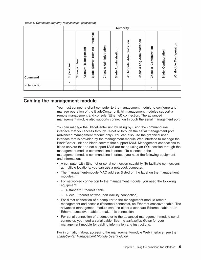
Table 1. Command authority relationships (continued)
Command
Authority
Su
per
viso
r
Ch
assi
s U
ser
Acc
ou
nt
Man
agem
ent
Bla
de
Ser
ver
Rem
ote
P
rese
nce
Ch
assi
s A
dm
inis
trat
ion
Bla
de
Ad
min
istr
atio
n
I/O M
od
ule
A
dm
inis
trat
ion
Ch
assi
s L
og
A
dm
inis
trat
ion
Ch
assi
s C
on
fig
ura
tio
n
Bla
de
Co
nfi
gu
rati
on
I/O M
od
ule
C
on
fig
ura
tio
n
write -config
v
v
Cabling the management module
You must connect a client computer to the management module to configure and
manage operation of the BladeCenter unit. All management modules support a
remote management and console (Ethernet) connection. The advanced
management module also supports connection through the serial management port.
You can manage the BladeCenter unit by using by using the command-line
interface that you access through Telnet or through the serial management port
(advanced management module only). You can also use the graphical user
interface that is provided by the management-module Web interface to manage the
BladeCenter unit and blade servers that support KVM. Management connections to
blade servers that do not support KVM are made using an SOL session through the
management-module command-line interface. To connect to the
management-module command-line interface, you need the following equipment
and information:
v A computer with Ethernet or serial connection capability. To facilitate connections
at multiple locations, you can use a notebook computer.
v The management-module MAC address (listed on the label on the management
module).
v For networked connection to the management module, you need the following
equipment:
– A standard Ethernet cable
– A local Ethernet network port (facility connection)
v For direct connection of a computer to the management-module remote
management and console (Ethernet) connector, an Ethernet crossover cable. The
advanced management module can use either a standard Ethernet cable or an
Ethernet crossover cable to make this connection.
v For serial connection of a computer to the advanced management-module serial
connector, you need a serial cable. See the Installation Guide for your
management module for cabling information and instructions.
For information about accessing the management-module Web interface, see the
BladeCenter Management Module User’s Guide.
Chapter 2. Using the command-line interface 9

The following sections describe how to cable to the management module to perform
initial configuration of the BladeCenter unit. See the Installation Guide for your
management module for specific cabling instructions.
Networked connection
Connect one end of a Category 5 or higher Ethernet cable to the remote
management and console (Ethernet) connector on the management module.
Connect the other end of the Ethernet cable to the facility network.
Direct connection
Connect one end of a Category 5 or higher Ethernet cable (advanced management
module only) or a Category 5 or higher Ethernet crossover cable (management
module and advanced management module) to the remote management and
console (Ethernet) connector on the management module. Connect the other end of
the cable to the Ethernet connector on the client computer.
Serial connection (advanced management module only)
Connect one end of a serial cable to the serial connector on the management
module. Connect the other end of the serial cable to the serial connector on the
client computer. See the Installation Guide for your management module for cabling
information and instructions.
Starting the command-line interface
Access the management-module command-line interface from a client computer by
establishing a Telnet connection to the IP address of the management module or by
establishing a Secure Shell (SSH) connection. For the advanced management
module, you can also access the command-line interface using a serial connection.
You can establish up to 20 separate Telnet, serial, or SSH sessions to the
BladeCenter management module, giving you the ability to have 20 command-line
interface sessions active at the same time.
Although a remote network administrator can access the management-module
command-line interface through Telnet, this method does not provide a secure
connection. As a secure alternative to using Telnet to access the command-line
interface, use a serial or SSH connection. SSH ensures that all data that is sent
over the network is encrypted and secure.
The following SSH clients are available. While some SSH clients have been tested,
support or non-support of any particular SSH client is not implied.
v The SSH clients distributed with operating systems such as Linux®, AIX®, and
UNIX® (see your operating-system documentation for information). The SSH
client of Red Hat Linux 8.0 Professional was used to test the command-line
interface.
v The SSH client of cygwin (see http://www.cygwin.com for information)
v Putty (see http://www.chiark.greenend.org.uk/~sgtatham/putty for information)
The following table shows the types of encryption algorithms that are supported,
based on the client software version that is being used.
Algorithm SSH version 1.5 clients SSH version 2.0 clients
Public key exchange SSH 1-key exchange algorithm Diffie-Hellman-group 1-sha-1
Host key type RSA (1024-bit) DSA (1024-bit)
10 IBM BladeCenter: Management Module Command-Line Interface Reference Guide
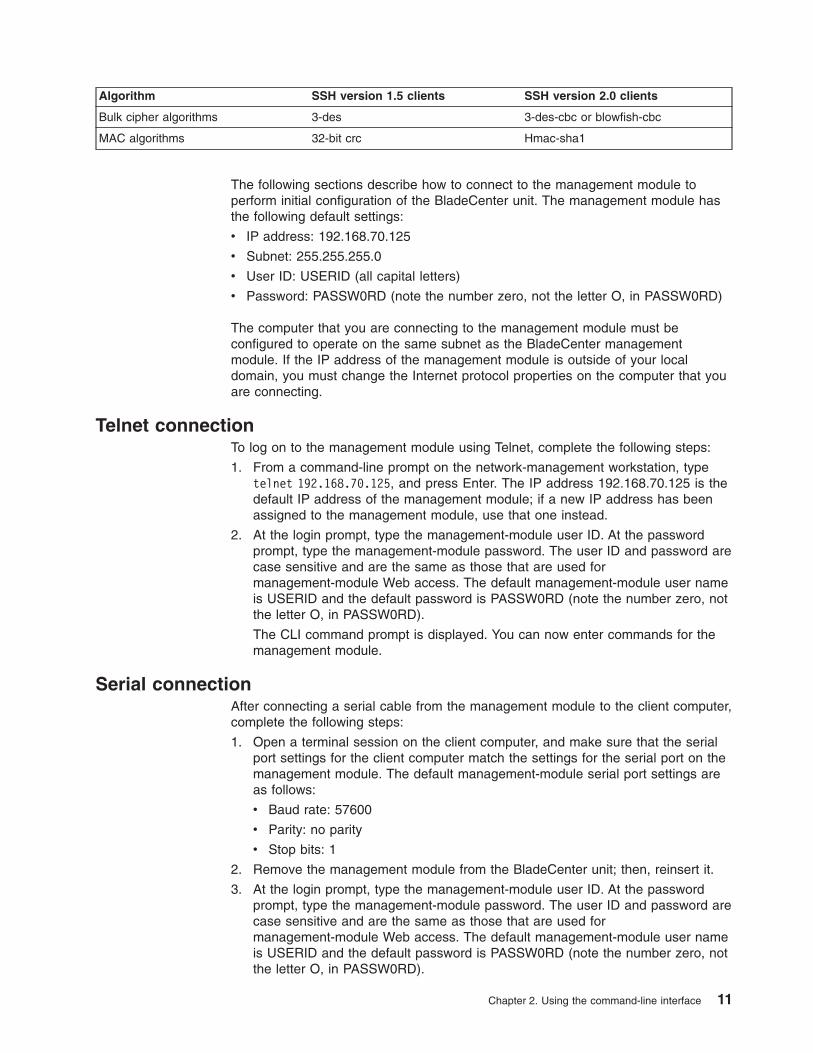
Algorithm SSH version 1.5 clients SSH version 2.0 clients
Bulk cipher algorithms 3-des 3-des-cbc or blowfish-cbc
MAC algorithms 32-bit crc Hmac-sha1
The following sections describe how to connect to the management module to
perform initial configuration of the BladeCenter unit. The management module has
the following default settings:
v IP address: 192.168.70.125
v Subnet: 255.255.255.0
v User ID: USERID (all capital letters)
v Password: PASSW0RD (note the number zero, not the letter O, in PASSW0RD)
The computer that you are connecting to the management module must be
configured to operate on the same subnet as the BladeCenter management
module. If the IP address of the management module is outside of your local
domain, you must change the Internet protocol properties on the computer that you
are connecting.
Telnet connection
To log on to the management module using Telnet, complete the following steps:
1. From a command-line prompt on the network-management workstation, type
telnet 192.168.70.125, and press Enter. The IP address 192.168.70.125 is the
default IP address of the management module; if a new IP address has been
assigned to the management module, use that one instead.
2. At the login prompt, type the management-module user ID. At the password
prompt, type the management-module password. The user ID and password are
case sensitive and are the same as those that are used for
management-module Web access. The default management-module user name
is USERID and the default password is PASSW0RD (note the number zero, not
the letter O, in PASSW0RD).
The CLI command prompt is displayed. You can now enter commands for the
management module.
Serial connection
After connecting a serial cable from the management module to the client computer,
complete the following steps:
1. Open a terminal session on the client computer, and make sure that the serial
port settings for the client computer match the settings for the serial port on the
management module. The default management-module serial port settings are
as follows:
v Baud rate: 57600
v Parity: no parity
v Stop bits: 1
2. Remove the management module from the BladeCenter unit; then, reinsert it.
3. At the login prompt, type the management-module user ID. At the password
prompt, type the management-module password. The user ID and password are
case sensitive and are the same as those that are used for
management-module Web access. The default management-module user name
is USERID and the default password is PASSW0RD (note the number zero, not
the letter O, in PASSW0RD).
Chapter 2. Using the command-line interface 11

The CLI command prompt is displayed. You can now enter commands for the
management module.
Secure Shell (SSH) connection
To log on to the management module using SSH, complete the following steps:
1. Make sure that the SSH service on the network-management workstation is
enabled. See your operating-system documentation for instructions.
2. Make sure that the SSH server on the BladeCenter management module is
enabled. See the IBM BladeCenter Management Module User’s Guide for
instructions.
3. Start an SSH session to the management module using the SSH client of your
choice. For example, if you are using the cygwin client, from a command-line
prompt on the network-management workstation, type ssh 192.168.70.125, and
press Enter. The IP address 192.168.70.125 is the default IP address of the
management module; if a new IP address has been assigned to the
management module, use that one instead.
4. Type the management-module user ID when prompted. At the password prompt,
type the management-module password. The user ID and password are case
sensitive and are the same as those that are used for management-module
Web access. The default management-module user name is USERID and the
default password is PASSW0RD (note the number zero, not the letter O, in
PASSW0RD).
The CLI command prompt is displayed. You can now enter commands for the
management module.
BladeCenter unit configuration
The BladeCenter unit automatically detects the modules and blade servers that are
installed and stores the vital product data (VPD). When the BladeCenter unit is
started, the management module automatically configures the remote management
port of the management module, so that you can configure and manage
BladeCenter components. You configure and manage BladeCenter components
remotely using the management-module command-line interface (CLI) or the
management-module Web interface.
To communicate with network resources and with the I/O modules in the
BladeCenter unit, you must configure IP addresses for the management module
and I/O modules. Management-module IP addresses can be configured using the
Web interface or command-line interface. There are several ways to configure the
I/O modules: through the management-module Web interface, or through an
external I/O-module port enabled through the management module, using a Telnet
interface, serial connection (advanced management module only), or a Web
browser. See the documentation that comes with each I/O module for information
and instructions.
To communicate with the blade servers for functions such as deploying an operating
system or application program over a network, you must also configure at least one
external (in-band) port on an Ethernet switch module in I/O-module bay 1 or 2.
Note: If a pass-thru module is installed in I/O-module bay 1 or 2 (instead of an
Ethernet I/O module), you will need to configure the network switch that the
pass-thru module is connected to; see the documentation that comes with the
network switch for instructions.
12 IBM BladeCenter: Management Module Command-Line Interface Reference Guide

Configuring the management module
You configure only the primary (active) management module. The redundant
management module, if present, receives the configuration and status information
automatically from the primary management module when necessary. The
configuration information in this section applies to the primary management module,
which might be the only management module in the BladeCenter unit.
If the management module that you installed is a replacement for the only
management module in the BladeCenter unit, and you saved the configuration file
before replacing the management module, you can apply the saved configuration
file to the replacement management module. See “read command (advanced
management module only)” on page 45 for information about applying a saved
configuration file. Other management modules must have their configurations
restored using the management-module Web interface (see the BladeCenter
Management Module User’s Guide for information).
For the active management module to communicate, you must configure the IP
addresses for the following internal and external ports:
v The external Ethernet (remote management) port (eth0) of the management
module. The initial automatic management module configuration enables a
remote console to connect to the management module to configure the port
completely and to configure the rest of the BladeCenter unit.
v The internal Ethernet port (eth1) on the management module for communication
with the I/O modules. Internal Ethernet ports for the advanced management
module cannot be configured.
After you connect the active management module to the network, the Ethernet port
connection is configured in one of the following ways. Either of these actions
enables the Ethernet connection on the active management module.
v If you have an accessible, active, and configured dynamic host configuration
protocol (DHCP) server on the network, IP address, gateway address, subnet
mask, and DNS server IP address are set automatically. The host name is set to
the management-module MAC address by default, and the domain server cannot
change it.
v If the DHCP server does not respond within 3 minutes after the port is
connected, the management module uses the factory-defined static IP address
and default subnet address.
Important: You can not connect to the management module using the
factory-defined static IP address and default subnet address until after this 3-minute
period passes.
Note: If the IP configuration is assigned by the DHCP server, the network
administrator can use the MAC address of the management-module network
interface to find out what IP address is assigned.
To configure the management-module internal and external Ethernet ports,
complete the following steps:
1. Connect to the management-module command-line interface (see “Starting the
command-line interface” on page 10 for more information).
2. Configure the external Ethernet interface (eth0), using the ifconfig command
(see “ifconfig command” on page 40 for instructions).
Chapter 2. Using the command-line interface 13

3. For management modules other than the advanced management module,
configure the internal Ethernet interface (eth1), using the ifconfig command (see
“ifconfig command” on page 40 for instructions).
Notes:
a. The internal Ethernet management port on each I/O module provides for
communication with the management module. You configure this port by
configuring the IP address for the I/O module (see the BladeCenter
Management Module User’s Guide and the User’s Guide for your I/O
module type for information and instructions). Some types of I/O modules,
such as the pass-thru module, have no management port. See the
documentation that comes with each I/O module to determine what else you
must configure in the I/O module.
b. For I/O module communication with a remote management station, such as
the IBM Director server, through the management-module external Ethernet
port, the I/O module internal network interface and the management-module
internal and external interfaces must be on the same subnet.
c. To communicate with the blade servers for functions such as deploying an
operating system or application program, you also will need to configure at
least one external (in-band) port on an Ethernet I/O module.
Starting an SOL session
Note: Serial over LAN (SOL) must be enabled for both the BladeCenter unit and
the blade server before you can start an SOL session with the blade server. See
“sol (serial over LAN) command” on page 52 and the BladeCenter Serial over LAN
Setup Guide for information about setting up and enabling SOL.
After you start a Telnet or SSH session to the BladeCenter management module,
you can start an SOL session to any individual blade server that supports SOL.
Since you can start up to 20 separate Web interface, Telnet, serial (advanced
management module only), or SSH sessions to the BladeCenter management
module, this gives you the ability to have simultaneous SOL sessions active for
each blade server installed in the BladeCenter unit.
Start an SOL session using the console command, from the command line,
indicating the target blade server. For example, to start an SOL connection to the
blade server in blade bay 6, type
console -T system:blade[6]
Note: A blade server assembly that occupies more than one blade bay is identified
by the lowest bay number that it occupies.
Once an SOL session is started, all commands are sent to the blade server
specified by the console command until the SOL session is ended, regardless of
the persistent command target that was in effect before the SOL session.
See “sol (serial over LAN) command” on page 52 and the IBM BladeCenter Serial
over LAN Setup Guide for information about configuring a blade server for SOL.
See your operating-system documentation for information about SOL commands
that you can enter using the command-line interface.
14 IBM BladeCenter: Management Module Command-Line Interface Reference Guide

Ending an SOL session
To end an SOL session, press Esc followed by an open parenthesis:
Esc (
When the SOL session ends, the command-line interface will return to the
persistent command target that was in effect before the SOL session. If you want to
end the Telnet or SSH command-line session, type exit.
Note: Exiting an SOL session does not stop the flow of serial data.
Chapter 2. Using the command-line interface 15

16 IBM BladeCenter: Management Module Command-Line Interface Reference Guide

Chapter 3. Command reference
This section contains command function, usage information, and examples. It is
divided into the following subsections:
v “Built-in commands” on page 18
– env (environment) command
– help command
– history command
– list (system physical configuration) commandv “Common commands” on page 23
– health command
– identify (location LED) command
– info (configuration information) command
– update (update firmware) commandv “Configuration commands” on page 30
– alertentries command
– clear command
– dhcpinfo command
– displaysd command (advanced management module only)
– dns command
– ifconfig command
– portcfg command (advanced management module only)
– read command (advanced management module only)
– service command (advanced management module only)
– smtp command
– snmp command
– sol (serial over LAN) command
– tcpcmdmode command
– telnetcfg (Telnet configuration) command
– uplink (management module failover) command
– users (management-module users) command
– write command (advanced management module only)v “Event-log commands” on page 69
– clearlog command
– displaylog commandv “Power-control commands” on page 71
– boot command
– fuelg command
– power command
– reset commandv “Session commands” on page 79
– console command
– exit commandv “System management commands (for BladeCenter T only)” on page 81
– alarm command
Adding a -h, -help, or ? option to a command displays syntax help for that
command. For example, to display help for the environment command, type one of
the following commands:
v env -h
v env -help
v env ?
© Copyright IBM Corp. 2006 17

You can target a command to a device other than the one that is set as the default
by adding a -T option to a command. See “Selecting the command target” on page
4 for information.
Built-in commands
Use these commands to perform top-level functions within the command-line
interface:
v env (environment) command
v help command
v history command
v list (system physical configuration) command
env (environment) command
This command sets the persistent environment for commands that are entered
during the remainder of the current session. The persistent command environment
is indicated by the command prompt. When you start the command-line interface,
the persistent command environment is the BladeCenter unit, denoted as “system”
by the command prompt. You can target a single command to an environment other
than the one that is set as the default by adding a -T option to the command that
includes a valid target destination (see “Selecting the command target” on page 4
for information). Target environments can be specified using the full path name, or
using a partial path name based on the persistent command environment. Full path
names always begin with “system”. The levels in a path name are divided using a
colon “:”.
Table 2. env (environment) command
Function What it does Command Valid targets
Set BladeCenter unit as
command target
Sets the BladeCenter unit as the
persistent target for commands
during the current session. This is
the persistent command
environment you are in at the
beginning of each command-line
interface session, indicated by the
system> prompt.
env
env -T system
The env command can
be directed to any
installed device.
Set management
module as command
target
Sets the management module as
the persistent target for commands
during the current session.
env -T system:mm[x]
where x is the bay (1 or 2)
that identifies the
management module.
The env command can
be directed to any
installed device, in this
case
-T system:mm[x]
where x is the
management-module
bay number.
Set blade server as
command target
Sets the specified blade server as
the persistent target for commands
during the current session.
env -T system:blade[x]
where x is the blade bay
that identifies the blade
server. A blade server that
occupies more than one
blade bay is identified by
the lowest bay number
that it occupies.
The env command can
be directed to any
installed device, in this
case
-T system:blade[x]
where x is the blade
bay that identifies the
blade server.
18 IBM BladeCenter: Management Module Command-Line Interface Reference Guide

Table 2. env (environment) command (continued)
Function What it does Command Valid targets
Set blade server
integrated system
management processor
as command target
Sets the integrated system
management processor on the
specified blade server as the
persistent target for commands
during the current session.
env -T system:blade[x]:sp
where x is the blade bay
that identifies the blade
server on which the
integrated system
management processor is
installed. A blade server
that occupies more than
one blade bay is identified
by the lowest bay number
that it occupies.
The env command can
be directed to any
installed device, in this
case
-T system:blade[x]:sp
where x is the blade
bay that identifies the
blade server on which
the integrated system
management processor
is installed.
Set I/O (switch) module
as command target
Sets the specified I/O (switch)
module as the persistent target for
commands during the current
session.
env -T system:switch[x]
where x is the I/O (switch)
module bay where the I/O
(switch) module is
installed.
The env command can
be directed to any
installed device, in this
case
-T system:switch[x]
where x is the I/O
(switch) module bay
where the I/O (switch)
module is installed.
Example:
To set the persistent target of commands to the service processor on the blade
server in blade bay 5, while the BladeCenter unit is set as the default command
target, at the system> prompt, type
env -T system:blade[5]:sp
The following example shows the information that is returned:
system> env -T system:blade[5]:sp
OK
system:blade[5]:sp>
To set the persistent target of commands to the service processor on the blade
server in blade bay 5, while the BladeCenter unit is set as the default command
target, at the system> prompt, you can also type
env -T blade[5]:sp
The following example shows the information that is returned:
system> env -T blade[5]:sp
OK
system:blade[5]:sp>
To issue the reset command on the blade server in blade bay 5, while the
management module is set as the default command target, at the system:mm[x]>
prompt, type
reset -T system:blade[5]
Chapter 3. Command reference 19

help command
This command displays a list of all commands that are available in the
command-line interface with a brief description of each command. You can also
issue the help command by typing ?. Adding a -h, -help, or ? option to a command
displays syntax help for the command.
Table 3. help command
Function What it does Command Valid targets
Help Displays a list of commands and a
brief description of each command.
help Any installed device.
? Any installed device.
Example:
To display a list of commands, while management module 1 is set as the default
command target, at the system:mm[1]> prompt, type
help
The following example shows the information that is returned:
system:mm[1]> help
?- Display commands
alertentries- View/edit remote alert recipients
boot- Boot target
clear- Clear the config
clearlog- Clear the event log
console- Start SOL session to a blade
dhcpinfo- View DHCP server assigned settings
displaylog- Display event log entries
displaysd- Display service data
dns- View/edit DNS config
env- Set persistent command target
exit- Log off
health- View system health status
help- Display command list
history- Display command history
identify- Control target location LED
ifconfig- View/edit network interface config
info- Display identity and config of target
list- Display installed targets
portcfg- Serial port configuration
power- Control target power
read- Restore configuration from chassis
reset- Reset target
service- Enable debugging by service personnel
shutdown- Shutdown target
smtp- View/edit SMTP config
snmp- View/edit SNMP config
sol- View SOL status and view/edit SOL config
tcpcmdmode- View/edit TCP command mode config
telnetcfg- View/edit telnet config
update- Update firmware from TFTP server
users- View/edit user login profiles
alarm- Manage Telco System Management alarm(s)
write- Save configuration to chassis
Type "<command> -h" for individual command syntax help.
20 IBM BladeCenter: Management Module Command-Line Interface Reference Guide

[ ] is used for indexing (by bay number)
< > denotes a variable
{ } denotes optional arguments
| denotes choice
system:mm[1]>
To obtain help about the env command, type one of the following commands:
v env -h
v env -help
v env ?
history command
This command displays the last eight commands that were entered, allowing the
user to choose and re-enter one of these commands. You choose the command to
re-enter from the displayed list by typing an exclamation point (!) followed
immediately by the numeric designation the command is assigned in the list. You
can also recall one of the past eight previously entered commands using the
up-arrow and down-arrow keys.
Table 4. history command
Function What it does Command Valid targets
Command history Displays the last eight commands
that were entered.
history Any installed device.
Re-enter previous
command using
numeric designation
Re-enters a numerically-specified
command from the command
history.
!x
where x is the number of
the command (0 - 7) to
re-enter from the
command history list.
Any installed device.
Example:
To display a list of the last eight commands entered, while management module 1 is
set as the default command target, at the system:mm[1]> prompt, type
history
To re-enter the command designated by “2” in the command history, type
!2
The following example shows the information that is returned from these two
commands:
system:mm[1]> history
0 dns
1 dns -on
2 dns
3 dns -i1 192.168.70.29
4 dns
5 dns -i1 192.168.70.29 -on
6 dns
7 history
system:mm[1]> !2
Enabled
-i1 192.168.70.29
-i2 0.0.0.0
-i3 0.0.0.0
Chapter 3. Command reference 21

system:mm[1]>
list (system physical configuration) command
This command displays a list of devices present within the command target. It can
be used to determine how many management modules are installed in the
BladeCenter unit and which management module is set as primary.
Table 5. list (system physical configuration) command
Function What it does Command Valid targets
View command target Displays the current command
target. If a management-module
bay is the current command target,
it will be identified as primary or
redundant.
list Any installed device.
View system
configuration tree
Displays the tree structure of
devices present in the BladeCenter
unit, starting at the command target
level. If management-module bays
are part of the tree, they will be
identified as primary or redundant.
list -l depth
where depth is “all” or “a”
for full tree display, starting
at the command target
level.
Specifying a depth of “1”
displays the current
command target.
Specifying a depth of “2”
displays the content of the
current command target
plus one level below it.
Any installed device.
Example:
To display a list of devices installed in the BladeCenter unit, while the BladeCenter
unit is set as the persistent command environment, at the system> prompt, type
list -l a
(This is the command syntax that can be used to determine the primary
management module.)
The following example shows the information that is returned:
system> list -l a
system
mm[1] primary
power[4]
blower[1]
blower[2]
blade[1]
sp
dtr[1]
blade[5]
sp
blade[6]
sp
blade[7]
sp
blade[8]
sp
mt
22 IBM BladeCenter: Management Module Command-Line Interface Reference Guide

system>
Common commands
Use these commands to monitor and control operation of BladeCenter components
using the command-line interface:
v health command
v identify (location LED) command
v info (configuration information) command
v update (update firmware) command
health command
This command displays the current health status of the command target. It can also
be used to display the alerts that are active for the command target. You can only
specify one command target each time you run the health command.
Table 6. health command
Function What it does Command Valid targets
Display health status Displays the current health status of
the command target. Return values
are different for the BladeCenter
and BladeCenter T configurations.
v Possible return values for the
BladeCenter configuration are:
– ok
– warning
– criticalv Possible return values for the
BladeCenter T configurations are:
– ok
– minor
– major
– critical
health -T system
-T system:mm[x]
-T system:blade[x]
-T system:switch[x]
-T system:power[x]
-T system:blower[x]
where x is the primary
management-module,
blade server, I/O
(switch) module, power
module, or blower bay
number.
Display health status
for tree
Displays the current health status of
the tree structure of devices present
in the BladeCenter unit, starting at
the command target level. If
management-module bays are part
of the tree, they will be identified as
primary or redundant. Return values
are different for the BladeCenter
and BladeCenter T configurations.
v Possible return values for the
BladeCenter configuration are:
– ok
– warning
– criticalv Possible return values for the
BladeCenter T configurations are:
– ok
– minor
– major
– critical
health -l depth
where depth is “2”, “all”, or
“a” for full tree display,
starting at the command
target level.
Specifying a depth of “1”
displays health status of
the current command
target.
-T system
-T system:mm[x]
-T system:blade[x]
-T system:switch[x]
-T system:power[x]
-T system:blower[x]
where x is the primary
management-module,
blade server, I/O
(switch) module, power
module, or blower bay
number.
Chapter 3. Command reference 23

Table 6. health command (continued)
Function What it does Command Valid targets
Display health status
and alerts
Displays the current health status
and active alerts for the command
target. Return values are different
for the BladeCenter and
BladeCenter T configurations.
v Possible return values for the
health status of the BladeCenter
configuration are:
– ok
– warning
– criticalv Possible return values for the
health status of the BladeCenter
T configurations are:
– ok
– minor
– major
– criticalv Active alert information provides
short text descriptions of alerts
that are active for each
monitored component.
The total amount of information
returned from the health -f
command is limited to 1024 bytes.
health -f -T system
-T system:mm[x]
-T system:blade[x]
-T system:switch[x]
-T system:power[x]
-T system:blower[x]
where x is the primary
management-module,
blade server, I/O
(switch) module, power
module, or blower bay
number.
Example:
To display the overall health status of the BladeCenter T unit, while the BladeCenter
T unit is set as the default command target, at the system> prompt, type
health
To display the health status of all components installed in the BladeCenter T unit,
that are valid command targets, while the BladeCenter T unit is set as the default
command target, at the system> prompt, type
health -l a
To display the health status of the blade server installed in blade bay 5, while the
BladeCenter T unit is set as the default command target, at the system> prompt,
type
health -T system:blade[5]
To display the health status and alerts for all components installed in the
BladeCenter T unit, that are valid command targets, while the BladeCenter T unit is
set as the default command target, at the system> prompt, type
health -l a -f
The following example shows the information that is returned from these
commands:
system> health
system:major
system> health -l a
system:major
mm[1]:ok
24 IBM BladeCenter: Management Module Command-Line Interface Reference Guide

blade[1]:ok
blade[3]:ok
blade[5]:minor
power[1]:ok
power[2]:minor
blower[1]:ok
blower[2]:ok
blower[3]:ok
blower[4]:ok
switch[1]:major
system> health -T system:blade[5]
blade[5]:minor
health -l a -f
system:major
blade[5]:minor
5V over voltage
CPU1 temperature warning
power[2]:minor
5V over voltage
switch[1]:major
temperature fault
system>
identify (location LED) command
This command controls operation of the location LED in a blade server or in the
BladeCenter unit. It can also be used to display the state of a location LED.
Table 7. identify (location LED) command
Function What it does Command Valid targets
Display location LED
state
Displays the current state of the
location LED in the command
target.
Possible LED states are:
v off
v on
v blink
identify -T system
-T system:blade[x]
where x is the blade
bay number.
Set location LED state Sets the state of the location LED
in the command target.
identify -s state
where state is “on”, “off”,
or “blink”.
Command use restricted
(see “Commands and user
authority” on page 5).
-T system
-T system:blade[x]
where x is the blade
bay number.
Turn on BladeCenter
unit location LED for
specified period of time
Turns on the location LED in the
BladeCenter unit for a specified
period of time before turning it off
automatically.
identify -s on -d time
where time is the number
of seconds the location
LED will remain lit.
Command use restricted
(see “Commands and user
authority” on page 5).
-T system
Chapter 3. Command reference 25

Example:
To display the status of the location LED in the blade server in blade bay 4, while
the BladeCenter unit is set as the persistent command environment, at the system>
prompt, type
identify -T system:blade[4]
To light the location LED in the blade server in blade bay 4, while the BladeCenter
unit is set as the persistent command environment, at the system> prompt, type
identify -s on -T system:blade[4]
The following example shows the information that is returned from a series of
identify commands:
system> identify -T system:blade[4]
-s off
system> identify -s on -T system:blade[4]
OK
system> identify -T system:blade[4]
-s on
system>
info (configuration information) command
This command displays information about BladeCenter components and their
configuration.
Table 8. info (configuration information) command
Function What it does Command Valid targets
Display component
information
Displays identification and
configuration information for the
command target.
info
Note: Only one target at a
time can be viewed with
the info command.
-T system:mm[x]
-T system:blade[x]
-T system:blade[x]
:dtr[x]
-T system:blade[x]:sp
-T system:blade[x]:be
-T system:switch[x]
-T system:power[x]
-T system:mt
where x is the
management-module
bay number, blade
server bay number, I/O
(switch) module bay
number, power module
bay number, or
daughter-card number.
Note: The command target -T system:blade[x]:dtr[x] is shown with a line break
before :dtr[x]. When this command target is entered, the entire entry must all be
on one line.
Example:
To view the information about the management module in management-module bay
1, while this management module is set as the persistent command environment, at
the system:mm[1]> prompt, type
info
26 IBM BladeCenter: Management Module Command-Line Interface Reference Guide

The following example shows the information that is returned from the info
command:
system:mm[1]> info
UUID: 0000 0000 0000 0000 0000 0000 0000 0000
Manuf ID: SLRM
Mach type/model: Management Module
Mach serial number: n/a
Manuf date: 4102
Part no.: 02R1606
FRU no.: 59P6622
FRU serial no.: J1P702A511F
Main application
Build ID: DVETXX-
File name: CNETMNUS.PKT
Rel date: 05-27-04
Rev: 16
Boot ROM
Build ID: BRBR14-
File name: CNETBRUS.PKT
Rel date: 09-12-02
Rev: 16
Remote control
Build ID: BRRG14-
File name: CNETRGUS.PKT
Rel date: 09-12-02
Rev: 16
system:mm[1]>
update (update firmware) command
This command updates firmware using a Trivial File Transfer Protocol (TFTP) server
and displays information about firmware installed in BladeCenter components.
Table 9. update (update firmware) command
Function What it does Command Valid targets
Display update
command help
Displays information about using
the update command.
update -T system:mm[x]
-T system:blade[x]:sp
-T system:switch[x]
where x is the primary
management-module,
blade server bay
number, or I/O (switch)
module bay number.
Display firmware
attributes
Displays attributes of the firmware
installed in the command target.
Return values are:
v Firmware type
v Build ID
v Filename
v Release date
v Revision level
update -a -T system:mm[x]
-T system:blade[x]:sp
-T system:switch[x]
where x is the primary
management-module,
blade server bay
number, or I/O (switch)
module bay number.
Chapter 3. Command reference 27

Table 9. update (update firmware) command (continued)
Function What it does Command Valid targets
Update firmware Update firmware for the command
target.
Important: Command authority
definitions might change between
firmware versions. Make sure that
the command authority level set for
each user is correct after updating
management-module firmware.
update -i ip_address -l
filelocation
where:
v ip_address is the IP
address of TFTP server.
v filelocation is the
location of the firmware
update file.
Command use restricted
(see “Commands and user
authority” on page 5).
-T system:mm[x]
-T system:blade[x]:sp
-T system:switch[x]
where x is the primary
management-module,
blade server bay
number, or I/O (switch)
module bay number.
Update firmware
(verbose)
Update firmware for the command
target, showing details of the
firmware download and flash
operations. The detailed information
is not shown until the update is
complete, which might take several
minutes.
Important: Command authority
definitions might change between
firmware versions. Make sure that
the command authority level set for
each user is correct after updating
management-module firmware.
update -i ip_address -l
filelocation -v
where:
v ip_address is the IP
address of TFTP server.
v filelocation is the
location of the firmware
update file.
Command use restricted
(see “Commands and user
authority” on page 5).
-T system:mm[x]
-T system:blade[x]:sp
-T system:switch[x]
where x is the primary
management-module,
blade server bay
number, or I/O (switch)
module bay number.
Example:
To update the firmware and display update details for the management module in
management-module bay 1, while this management module is set as the persistent
command environment, type the following command at the system:mm[1]> prompt.
For this example, the IP address of the TFTP server is 192.168.70.120 and the
firmware file containing the update is named dev_mm.pkt.
update -v -i 192.168.70.120 -l dev_mm.pkt
To display information about firmware installed in the management module in
management-module bay 1, while this management module is set as the persistent
command environment, at the system:mm[1]> prompt, type
update -a
To update the service-processor firmware in the blade server in blade bay 8 (not
using verbose mode), while the management module in management-module bay 1
is set as the persistent command environment, type the following command at the
system:mm[1]> prompt. For this example, the IP address of the TFTP server is
192.168.70.120 and the firmware file containing the update is named h8.pkt.
update -i 192.168.70.120 -l h8.pkt -T system:blade[8]:sp
The following example shows the information that is returned from these three
update commands:
system:mm[1]> update -v -i 192.168.70.120 -l dev_mm.pkt
TFTP file upload successful 1517829.
Starting flash packet preparation.
Flash preparation - packet percent complete 24.
28 IBM BladeCenter: Management Module Command-Line Interface Reference Guide

Flash preparation - packet percent complete 48.
Flash preparation - packet percent complete 72.
Flash preparation - packet percent complete 96.
Flash preparation - packet percent complete 100.
Flash operation phase starting.
Flashing - packet percent complete 34.
Flashing - packet percent complete 38.
Flashing - packet percent complete 50.
Flashing - packet percent complete 55.
Flashing - packet percent complete 80.
Flashing - packet percent complete 90.
Flash operation complete. The new firmware will become active after the next
reset of the MM.
OK
system:mm[1]> update -a
Bay 1 Name 1
Firmware type: Main application
Build ID: BRETKD+
Filename: CNETMNUS.PKT
Released: 11-17-03
Revision: 16
Firmware type: Boot ROM
Build ID: BRBR1B+
Filename: CNETBRUS.PKT
Released: 10-27-03
Revision: 16
Firmware type: Remote control
Build ID: BRRG1B+
Filename: CNETRGUS.PKT
Released: 10-27-03
Revision: 16
OK
system:mm[1]> update -i 192.168.70.120 -l h8.pkt -T system:blade[8]:sp
OK
system:mm[1]>
Chapter 3. Command reference 29

Configuration commands
Use these commands to view and configure network settings and Ethernet
interfaces:
v alertentries command
v clear command
v dhcpinfo command
v displaysd command (advanced management module only)
v dns command
v ifconfig command
v service command (advanced management module only)
v smtp command
v snmp command
v sol (serial over LAN) command
v tcpcmdmode command
v telnetcfg (Telnet configuration) command
v uplink (management module failover) command
v users (management-module users) command
alertentries command
This command manages the recipients of alerts generated by the primary
management module.
Table 10. alertentries command
Function What it does Command Valid targets
Display alert properties
for all recipients
Displays alert properties for all
management-module alert
recipients. Returned values for each
alert recipient are:
v recipient name
v notification method (E-Mail over
LAN/Director comp./SNMP over
LAN)
v type of alerts received (Receives
critical alerts only/Receives all
alerts/Disabled)
alertentries -T system:mm[x]
where x is the primary
management-module
bay number.
Display alert properties
for alert recipients
Displays alert properties for the
specified management-module alert
recipient profile. Returned values
are:
v -status alert_recipient_status
(on/off)
v -n alert_recipient_name
v -f alert_type (critical/none)
v -t notification_method
(email/director/snmp)
v -e email_address (used for
e-mail notifications)
v -i static_IP_addr/hostname (used
for IBM Director notifications)
alertentries -recip_number
where recip_number is a
number from 1 to 12 that
corresponds to the
recipient number assigned
in the “Display alert
properties for all
recipients” list.
-T system:mm[x]
where x is the primary
management-module
bay number.
30 IBM BladeCenter: Management Module Command-Line Interface Reference Guide

Table 10. alertentries command (continued)
Function What it does Command Valid targets
Delete alert recipient Delete the specified alert recipient. alertentries -recip_number
-del
where recip_number is a
number from 1 to 12 that
corresponds to the
recipient number assigned
in the “Display alert
properties for all
recipients” list. It is
possible to delete an
empty alert recipient.
Command use restricted
(see “Commands and user
authority” on page 5).
-T system:mm[x]
where x is the primary
management-module
bay number.
Chapter 3. Command reference 31

Table 10. alertentries command (continued)
Function What it does Command Valid targets
Create alert recipient Create the specified alert recipient.
All fields must be specified when
creating an alert recipient.
alertentries -recip_number
-n recip_name -status
alert_status -f filter_type -t
notification_method -e
email_addr -i
ip_addr/hostname
where:
v recip_number is a
number from 1 to 12
that corresponds to an
unused recipient
number in the “Display
alert properties for all
recipients” list.
v recip_name is a
alphanumeric string up
to 31 characters in
length containing any
character, including
spaces, except for angle
brackets ( < and > ). If
the string includes
spaces it must be
enclosed in
double-quotes.
v alert_status is on or off
for receipt of alerts.
v filter_type filters the
alert types received:
critical (receive critical
alerts only) or none
(receive all alerts).
v notification_method is
email, director (IBM
Director) or snmp.
– For e-mail, you must
specify an e-mail
address (-e
argument).
– For director, you
must specify an IP
address (-i
argument).
– If snmp is selected,
the -e and -i
arguments are not
needed.v email_addr is a valid
e-mail address string up
to 63 characters in
length.
(continued on next page)
-T system:mm[x]
where x is the primary
management-module
bay number.
32 IBM BladeCenter: Management Module Command-Line Interface Reference Guide

Table 10. alertentries command (continued)
Function What it does Command Valid targets
Create alert recipient
(continued)
v ip_addr/hostname is a
valid static IP address
or an alphanumeric
hostname string for the
recipient that is up to 49
characters in length that
can include periods ( . ),
hyphens ( - ), and
underscores ( _ ).
Command use restricted
(see “Commands and user
authority” on page 5).
Set alert recipient name Sets a name for the specified alert
recipient.
alertentries -recip_number
-n recip_name
where:
v recip_number is a
number from 1 to 12
that corresponds to the
recipient number
assigned in the “Display
alert properties for all
recipients” list.
v recip_name is a
alphanumeric string up
to 31 characters in
length that can include
any character, including
spaces, except for angle
brackets ( < and > ). If
the name includes
spaces it must be
enclosed in
double-quotes.
Command use restricted
(see “Commands and user
authority” on page 5).
-T system:mm[x]
where x is the primary
management-module
bay number.
Set alert recipient
status
Sets status for the specified alert
recipient. The status determines if a
recipient will receive alarm
notifications.
alertentries -recip_number
-status alert_status
where:
v recip_number is a
number from 1 to 12
that corresponds to the
recipient number
assigned in the “Display
alert properties for all
recipients” list.
v alert_status is on or off.
Command use restricted
(see “Commands and user
authority” on page 5).
-T system:mm[x]
where x is the primary
management-module
bay number.
Chapter 3. Command reference 33

Table 10. alertentries command (continued)
Function What it does Command Valid targets
Set alert types received Filters the types of alert that are
received by the specified alert
recipient.
alertentries -recip_number
-f filter_type
where:
v recip_number is a
number from 1 to 12
that corresponds to the
recipient number
assigned in the “Display
alert properties for all
recipients” list.
v alert_type filters the
alert types received:
critical (receive critical
alerts only) or none
(receive all alerts).
Command use restricted
(see “Commands and user
authority” on page 5).
-T system:mm[x]
where x is the primary
management-module
bay number.
Set alert notification
method
Sets the alert notification method
for the specified alert recipient.
alertentries -recip_number
-t notification_method
where:
v recip_number is a
number from 1 to 12
that corresponds to the
recipient number
assigned in the “Display
alert properties for all
recipients” list.
v notification_method is
email, director (IBM
Director) or snmp.
Command use restricted
(see “Commands and user
authority” on page 5).
-T system:mm[x]
where x is the primary
management-module
bay number.
Set alert recipient
e-mail address
Sets the e-mail address for the
specified alert recipient. This e-mail
address is used to send alerts to
the recipient via e-mail.
The e-mail address can be set only
if the alert notification method (-t
option) is set to email. The -t and -e
options can be combined within the
same command.
alertentries -recip_number
-e email_addr
where:
v recip_number is a
number from 1 to 12
that corresponds to the
recipient number
assigned in the “Display
alert properties for all
recipients” list.
v email_addr is a valid
e-mail address string up
to 63 characters in
length.
Command use restricted
(see “Commands and user
authority” on page 5).
-T system:mm[x]
where x is the primary
management-module
bay number.
34 IBM BladeCenter: Management Module Command-Line Interface Reference Guide

Table 10. alertentries command (continued)
Function What it does Command Valid targets
Set alert recipient IP
address or hostname
Sets the IP address or hostname
used to send alert notifications to
the specified alert recipient using
IBM Director.
The IP address or hostname used
to send alert notifications can be
set only if the alert notification
method (-t option) is set to director
(IBM Director). The -t and -i options
can be combined within the same
command.
alertentries -recip_number
-i ip_addr/hostname
where:
v recip_number is a
number from 1 to 12
that corresponds to the
recipient number
assigned in the “Display
alert properties for all
recipients” list.
v ip_addr/hostname is a
valid static IP address
or an alphanumeric
hostname string up to
49 characters in length
that can include periods
( . ), hyphens ( - ), and
underscores ( _ ).
Command use restricted
(see “Commands and user
authority” on page 5).
-T system:mm[x]
where x is the primary
management-module
bay number.
Example:
To view the configuration for alert recipient 1, while management module 1 is set as
the persistent command environment, at the system:mm[1]> prompt, type
alertentries -1
To configure alert recipient 2 to receive only critical alert notifications by e-mail,
while management module 1 is set as the persistent command environment, at the
system:mm[1]> prompt, type
alertentries -2 -n test2 -status on -f critical -t email -e [email protected]
To configure alert recipient 3 to receive all alert notifications through IBM Director,
while management module 1 is set as the persistent command environment, at the
system:mm[1]> prompt, type
alertentries -3 -n test3 -status on -f none -t director -i 192.168.70.140
To configure alert recipient 4 to receive all alert notifications through SNMP, while
management module 1 is set as the persistent command environment, at the
system:mm[1]> prompt, type
alertentries -4 -n test4 -status on -f none -t snmp
The following example shows the information that is returned from these
commands:
system:mm[1]> alertentries -1
-status on
-n test1
-f critical
-t email
system:mm[1]> alertentries -2 -n test2 -status on -f critical -t email
Chapter 3. Command reference 35

OK
system:mm[1]> alertentries -3 -n test3 -status on -f none -t director
-i 192.168.70.140
OK
system:mm[1]> alertentries -4 -n test4 -status on -f none -t snmp
OK
system:mm[1]>
clear command
This command restores the primary management module configuration or an I/O
(switch) module configuration to the default settings. The command must always
include the -config option.
Table 11. clear command
Function What it does Command Valid targets
Restore default
configuration of primary
management module
Restores the default configuration
of the primary management
module; then, resets the
management module.
No results are returned from this
command because it resets the
management module.
When you restore the
management-module configuration,
the Ethernet configuration method
is set to a value of dthens. After the
management module resets, this
causes the management module to
try dhcp configuration and then
default to the static IP configuration,
which might cause the management
module to remain offline for longer
than normal. See the “ifconfig
command” on page 40 for
information.
clear -config
Command use restricted
(see “Commands and user
authority” on page 5).
-T system:mm[x]
where x is the primary
management-module
bay number.
Restore default
configuration of I/O
(switch) module
Restores the configuration of the
specified I/O (switch) module to the
default settings.
clear -config
Command use restricted
(see “Commands and user
authority” on page 5).
-T system:switch[x]
where x is the I/O
(switch) module bay
number.
Example:
To restore the primary management-module configuration to default settings, while
management module 1 is set as the persistent command environment, at the
system:mm[1]> prompt, type
clear -config
No results are returned from this command. After the management module resets,
you will need to start a new command-line session.
36 IBM BladeCenter: Management Module Command-Line Interface Reference Guide

dhcpinfo command
This command displays the IP configuration that is assigned to the primary
management module by the DHCP server.
Note: The dhcpinfo command does not apply to eth1, which always uses a static
IP configuration.
Table 12. dhcpinfo command
Function What it does Command Valid targets
Display Ethernet
channel 0 DHCP
configuration
If the IP configuration for eth0 is
assigned by a DHCP server, the
configuration that is assigned by the
DHCP server and DHCP server
information is displayed. If the IP
configuration for eth0 is not
assigned by a DHCP server, an
error message is displayed.
Possible configuration values
returned are:
v -server dhcp_ip_address
v -n hostname
v -i ip_address
v -g gateway_address
v -s subnet_mask
v -d domainname
v -dns1 primary _dns_ip_address
v -dns2 secondary
_dns_ip_address
v -dns3 tertiary _dns_ip_1address
dhcpinfo -eth0 -T system:mm[x]
where x is the primary
management-module
bay number.
Example:
To display the DHCP server assigned network settings for Ethernet channel 0, while
management module 1 is set as the persistent command environment, at the
system:mm[1]> prompt, type
dhcpinfo -eth0
The following example shows the information that is returned:
system:mm[1]> dhcpinfo -eth0
-server 192.168.70.29
-n MM00096BCA0C80
-i 192.168.70.183
-g 192.168.70.29
-s 255.255.255.0
-d linux-sp.raleigh.ibm.com
-dns1 192.168.70.29
-dns2 0.0.0.0
-dns3 0.0.0.0
system:mm[1]>
Chapter 3. Command reference 37

displaysd command (advanced management module only)
This command captures and displays service information. Service information
includes BladeCenter VPD, the management-module event log, and self-test results
from the primary management module. If multiple user interface sessions issue the
displaysd command, the commands will be processed in the order that they are
received.
Table 13. displaysd command
Function What it does Command Valid targets
Display service
information
Display service information on
screen from last service information
capture.
displaysd -T system
Capture and display
service information
Capture and display service
information on screen.
displaysd -c -T system
Example:
To capture service information, while the chassis is set as the persistent command
environment, at the system> prompt, type
displaysd -c
The following example shows the information that is returned:
system> displaysd -c
SPAPP Capture Available
Time: 10/04/2005 21:47:43
UUID: Not Available
v
v
v
system:mm[1]>
Note: If a large amount of service information is available, display could exceed the
capacity of your command prompt window, resulting in loss of information displayed
at the start of the data set. If this happens, you will need to clear the
management-module event log to reduce the amount of information being captured.
dns command
This command configures and displays the management-module DNS settings.
Table 14. dns command
Function What it does Command Valid targets
Display DNS
configuration of
management module
Displays the current DNS
configuration of the management
module. Possible return values are:
v enabled
v disabled
v -i1 first ip_address
v -i2 second ip_address
v -i3 third ip_address
dns -T system:mm[x]
where x is the primary
management-module
bay number.
DNS - enable Enables the management-module
DNS configuration.
dns -on
Command use restricted
(see “Commands and user
authority” on page 5).
-T system:mm[x]
where x is the primary
management-module
bay number.
38 IBM BladeCenter: Management Module Command-Line Interface Reference Guide

Table 14. dns command (continued)
Function What it does Command Valid targets
DNS - disable Disables the management-module
DNS configuration.
dns -off
Command use restricted
(see “Commands and user
authority” on page 5).
-T system:mm[x]
where x is the primary
management-module
bay number.
DNS first IP address -
set
Checks syntax and sets the first IP
address.
dns -i1 ip_address
where ip_address is the
first IP address.
Command use restricted
(see “Commands and user
authority” on page 5).
-T system:mm[x]
where x is the primary
management-module
bay number.
DNS second IP address
- set
Checks syntax and sets the second
IP address.
dns -i2 ip_address
where ip_address is the
second IP address.
Command use restricted
(see “Commands and user
authority” on page 5).
-T system:mm[x]
where x is the primary
management-module
bay number.
DNS third IP address -
set
Checks syntax and sets the third IP
address.
dns -i3 ip_address
where ip_address is the
third IP address.
Command use restricted
(see “Commands and user
authority” on page 5).
-T system:mm[x]
where x is the primary
management-module
bay number.
Example:
To set the first IP address of the management-module DNS server to 192.168.70.29
and enable DNS on the primary management module, while management module 1
is set as the persistent command environment, at the system:mm[1]> prompt, type
dns -i1 192.168.70.29 -on
To display the DNS status of the primary management module, while management
module 1 is set as the persistent command environment, at the system:mm[1]>
prompt, type
dns
The following example shows the information that is returned from these two
commands:
system:mm[1]> dns -i1 192.168.70.29 -on
Changes to the network settings will take effect after the next reset of the MM.
system:mm[1]> dns
Enabled
-i1 192.168.70.29
-i2 0.0.0.0
-i3 0.0.0.0
system:mm[1]>
Chapter 3. Command reference 39
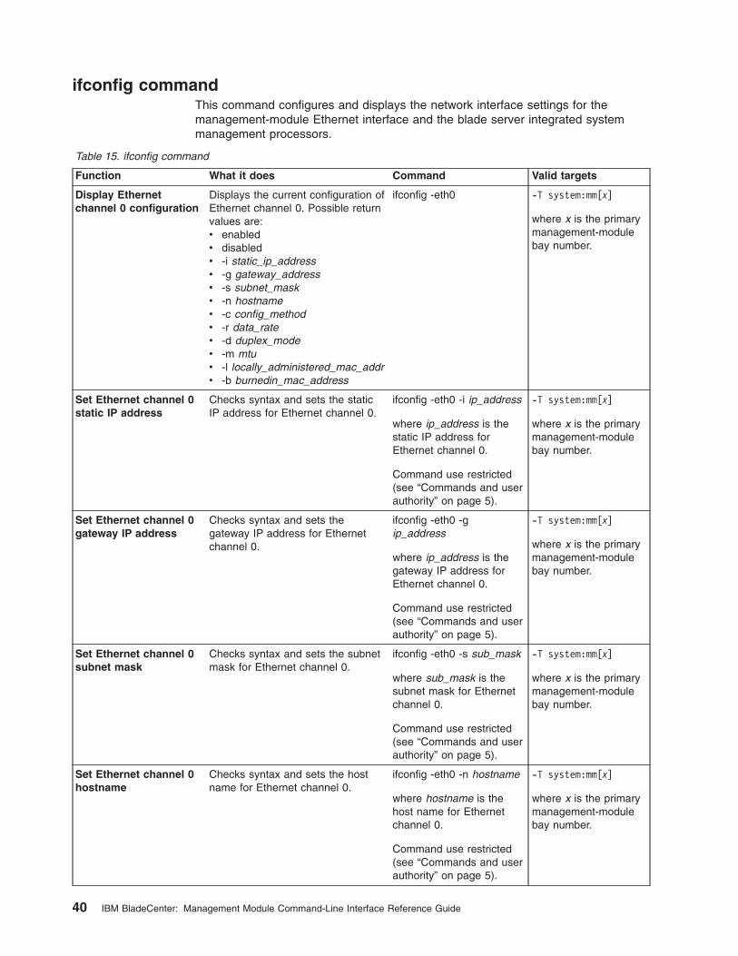
ifconfig command
This command configures and displays the network interface settings for the
management-module Ethernet interface and the blade server integrated system
management processors.
Table 15. ifconfig command
Function What it does Command Valid targets
Display Ethernet
channel 0 configuration
Displays the current configuration of
Ethernet channel 0. Possible return
values are:
v enabled
v disabled
v -i static_ip_address
v -g gateway_address
v -s subnet_mask
v -n hostname
v -c config_method
v -r data_rate
v -d duplex_mode
v -m mtu
v -l locally_administered_mac_addr
v -b burnedin_mac_address
ifconfig -eth0 -T system:mm[x]
where x is the primary
management-module
bay number.
Set Ethernet channel 0
static IP address
Checks syntax and sets the static
IP address for Ethernet channel 0.
ifconfig -eth0 -i ip_address
where ip_address is the
static IP address for
Ethernet channel 0.
Command use restricted
(see “Commands and user
authority” on page 5).
-T system:mm[x]
where x is the primary
management-module
bay number.
Set Ethernet channel 0
gateway IP address
Checks syntax and sets the
gateway IP address for Ethernet
channel 0.
ifconfig -eth0 -g
ip_address
where ip_address is the
gateway IP address for
Ethernet channel 0.
Command use restricted
(see “Commands and user
authority” on page 5).
-T system:mm[x]
where x is the primary
management-module
bay number.
Set Ethernet channel 0
subnet mask
Checks syntax and sets the subnet
mask for Ethernet channel 0.
ifconfig -eth0 -s sub_mask
where sub_mask is the
subnet mask for Ethernet
channel 0.
Command use restricted
(see “Commands and user
authority” on page 5).
-T system:mm[x]
where x is the primary
management-module
bay number.
Set Ethernet channel 0
hostname
Checks syntax and sets the host
name for Ethernet channel 0.
ifconfig -eth0 -n hostname
where hostname is the
host name for Ethernet
channel 0.
Command use restricted
(see “Commands and user
authority” on page 5).
-T system:mm[x]
where x is the primary
management-module
bay number.
40 IBM BladeCenter: Management Module Command-Line Interface Reference Guide
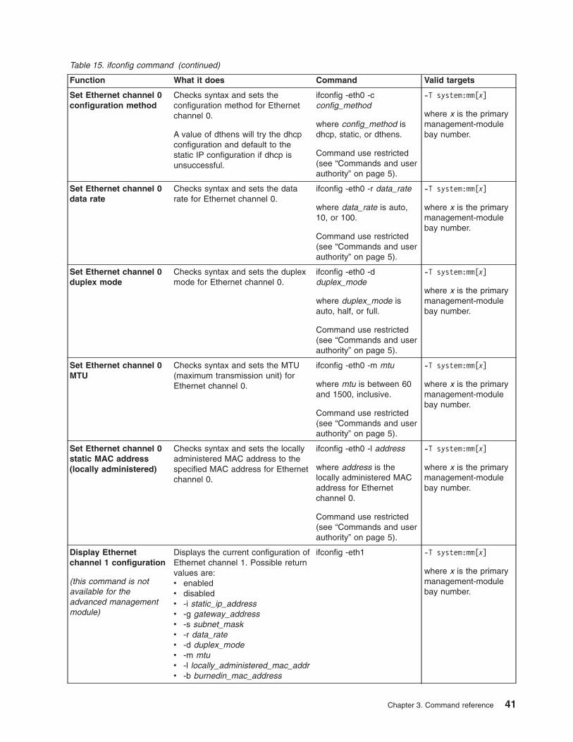
Table 15. ifconfig command (continued)
Function What it does Command Valid targets
Set Ethernet channel 0
configuration method
Checks syntax and sets the
configuration method for Ethernet
channel 0.
A value of dthens will try the dhcp
configuration and default to the
static IP configuration if dhcp is
unsuccessful.
ifconfig -eth0 -c
config_method
where config_method is
dhcp, static, or dthens.
Command use restricted
(see “Commands and user
authority” on page 5).
-T system:mm[x]
where x is the primary
management-module
bay number.
Set Ethernet channel 0
data rate
Checks syntax and sets the data
rate for Ethernet channel 0.
ifconfig -eth0 -r data_rate
where data_rate is auto,
10, or 100.
Command use restricted
(see “Commands and user
authority” on page 5).
-T system:mm[x]
where x is the primary
management-module
bay number.
Set Ethernet channel 0
duplex mode
Checks syntax and sets the duplex
mode for Ethernet channel 0.
ifconfig -eth0 -d
duplex_mode
where duplex_mode is
auto, half, or full.
Command use restricted
(see “Commands and user
authority” on page 5).
-T system:mm[x]
where x is the primary
management-module
bay number.
Set Ethernet channel 0
MTU
Checks syntax and sets the MTU
(maximum transmission unit) for
Ethernet channel 0.
ifconfig -eth0 -m mtu
where mtu is between 60
and 1500, inclusive.
Command use restricted
(see “Commands and user
authority” on page 5).
-T system:mm[x]
where x is the primary
management-module
bay number.
Set Ethernet channel 0
static MAC address
(locally administered)
Checks syntax and sets the locally
administered MAC address to the
specified MAC address for Ethernet
channel 0.
ifconfig -eth0 -l address
where address is the
locally administered MAC
address for Ethernet
channel 0.
Command use restricted
(see “Commands and user
authority” on page 5).
-T system:mm[x]
where x is the primary
management-module
bay number.
Display Ethernet
channel 1 configuration
(this command is not
available for the
advanced management
module)
Displays the current configuration of
Ethernet channel 1. Possible return
values are:
v enabled
v disabled
v -i static_ip_address
v -g gateway_address
v -s subnet_mask
v -r data_rate
v -d duplex_mode
v -m mtu
v -l locally_administered_mac_addr
v -b burnedin_mac_address
ifconfig -eth1 -T system:mm[x]
where x is the primary
management-module
bay number.
Chapter 3. Command reference 41

Table 15. ifconfig command (continued)
Function What it does Command Valid targets
Set Ethernet channel 1
static IP address
(this command is not
available for the
advanced management
module)
Checks syntax and sets the static
IP address for Ethernet channel 1.
ifconfig -eth1 -i ip_address
where ip_address is the
static IP address for
Ethernet channel 1.
Command use restricted
(see “Commands and user
authority” on page 5).
-T system:mm[x]
where x is the primary
management-module
bay number.
Set Ethernet channel 1
gateway IP address
(this command is not
available for the
advanced management
module)
Checks syntax and sets the
gateway IP address for Ethernet
channel 1.
ifconfig -eth1 -g
ip_address
where ip_address is the
gateway IP address for
Ethernet channel 1.
Command use restricted
(see “Commands and user
authority” on page 5).
-T system:mm[x]
where x is the primary
management-module
bay number.
Set Ethernet channel 1
subnet mask
(this command is not
available for the
advanced management
module)
Checks syntax and sets the subnet
mask for Ethernet channel 1.
ifconfig -eth1 -s sub_mask
where sub_mask is the
subnet mask for Ethernet
channel 1.
Command use restricted
(see “Commands and user
authority” on page 5).
-T system:mm[x]
where x is the primary
management-module
bay number.
Set Ethernet channel 1
static MAC address
(locally administered)
(this command is not
available for the
advanced management
module)
Checks syntax and sets the locally
administered MAC address to the
specified MAC address for Ethernet
channel 1.
ifconfig -eth1 -l address
where address is the
locally administered MAC
address for Ethernet
channel 1.
Command use restricted
(see “Commands and user
authority” on page 5).
-T system:mm[x]
where x is the primary
management-module
bay number.
Enable Ethernet
channel 1
(this command is not
available for the
advanced management
module)
Enables Ethernet channel 1. ifconfig -eth1 -up
Command use restricted
(see “Commands and user
authority” on page 5).
-T system:mm[x]
where x is the primary
management-module
bay number.
Disable Ethernet
channel 1
(this command is not
available for the
advanced management
module)
Disables Ethernet channel 1. ifconfig -eth1 -down
Command use restricted
(see “Commands and user
authority” on page 5).
-T system:mm[x]
where x is the primary
management-module
bay number.
42 IBM BladeCenter: Management Module Command-Line Interface Reference Guide

Table 15. ifconfig command (continued)
Function What it does Command Valid targets
Set starting IP address
for blade server
integrated system
management processor
Sets the starting point of the
integrated system management
processor IP addresses for blade
servers that are installed in the
BladeCenter unit.
ifconfig -i ip_address
where ip_address is the
starting IP address for all
blade servers that are
installed in the
BladeCenter unit.
Command use restricted
(see “Commands and user
authority” on page 5).
-T system:blade[1]:sp
Example:
To display the configuration for Ethernet channel 0, while management module 1 is
set as the persistent command environment, at the system:mm[1]> prompt, type
ifconfig -eth0
To set the static IP address for Ethernet channel 0 to 192.168.70.133, while
management module 1 is set as the persistent command environment, at the
system:mm[1]> prompt, type
ifconfig -eth0 -i 192.168.70.133 -c static
The following example shows the information that is returned from these two
commands:
system:mm[1]> ifconfig -eth0
Enabled
-i 10.10.10.10
-g 0.0.0.0
-s 255.255.255.0
-n MM00096BCA0C80
-c Try DHCP server. If it fails, use static IP config.
-r Auto
-d Auto
-m 1500
-l 00:00:00:00:00:00
-b 00:09:6B:CA:0C:80
system:mm[1]> ifconfig -eth0 -i 192.168.70.133 -c static
Changes to the network settings will take effect after the next reset of the MM.
system:mm[1]>
Chapter 3. Command reference 43

portcfg command (advanced management module only)
This command configures and displays the settings for the advanced
management-module serial port.
Table 16. portcfg command
Function What it does Command Valid targets
Display
management-module
serial port configuration
Displays the current configuration of
the management-module serial port.
Possible return values are:
v -b baud_rate
v -p parity
v -s stop_bits
portcfg -com1 -T system:mm[x]
where x is the primary
management-module
bay number.
Set management-module serial port baud
rate
Checks syntax and sets the baud
(communications) rate of the
management-module serial port.
portcfg -com1 -b
baud_rate
where baud_rate is 2400,
4800, 9600, 19200, 38400,
57600, or 115200.
Command use restricted
(see “Commands and user
authority” on page 5).
-T system:mm[x]
where x is the primary
management-module
bay number.
Set management-module serial port
parity
Checks syntax and sets the parity
of the management-module serial
port.
portcfg -com1 -p parity
where parity is none, odd,
even, mark, or space.
Command use restricted
(see “Commands and user
authority” on page 5).
-T system:mm[x]
where x is the primary
management-module
bay number.
Set management-module serial port stop
bits
Checks syntax and sets the number
of stop bits for the
management-module serial port.
portcfg -com1 -s stop_bits
where stop_bits is 1 or 2.
Command use restricted
(see “Commands and user
authority” on page 5).
-T system:mm[x]
where x is the primary
management-module
bay number.
Example:
To display the configuration for the management-module serial port, while
management module 1 is set as the persistent command environment, at the
system:mm[1]> prompt, type
portcfg -com1
To set the baud rate for the management-module serial port to 9600, while
management module 1 is set as the persistent command environment, at the
system:mm[1]> prompt, type
portcfg -com1 -b 9600
The following example shows the information that is returned from these two
commands:
system:mm[1]> portcfg -com1
-b 2400
-p odd
-s 1
44 IBM BladeCenter: Management Module Command-Line Interface Reference Guide
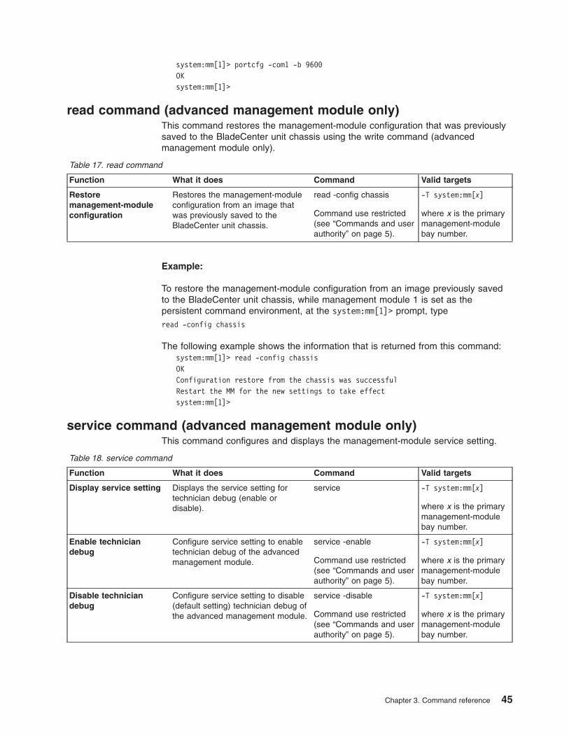
system:mm[1]> portcfg -com1 -b 9600
OK
system:mm[1]>
read command (advanced management module only)
This command restores the management-module configuration that was previously
saved to the BladeCenter unit chassis using the write command (advanced
management module only).
Table 17. read command
Function What it does Command Valid targets
Restore
management-module
configuration
Restores the management-module
configuration from an image that
was previously saved to the
BladeCenter unit chassis.
read -config chassis
Command use restricted
(see “Commands and user
authority” on page 5).
-T system:mm[x]
where x is the primary
management-module
bay number.
Example:
To restore the management-module configuration from an image previously saved
to the BladeCenter unit chassis, while management module 1 is set as the
persistent command environment, at the system:mm[1]> prompt, type
read -config chassis
The following example shows the information that is returned from this command:
system:mm[1]> read -config chassis
OK
Configuration restore from the chassis was successful
Restart the MM for the new settings to take effect
system:mm[1]>
service command (advanced management module only)
This command configures and displays the management-module service setting.
Table 18. service command
Function What it does Command Valid targets
Display service setting Displays the service setting for
technician debug (enable or
disable).
service -T system:mm[x]
where x is the primary
management-module
bay number.
Enable technician
debug
Configure service setting to enable
technician debug of the advanced
management module.
service -enable
Command use restricted
(see “Commands and user
authority” on page 5).
-T system:mm[x]
where x is the primary
management-module
bay number.
Disable technician
debug
Configure service setting to disable
(default setting) technician debug of
the advanced management module.
service -disable
Command use restricted
(see “Commands and user
authority” on page 5).
-T system:mm[x]
where x is the primary
management-module
bay number.
Chapter 3. Command reference 45

Example:
To enable technician debug of the advanced management module, while
management module 1 is set as the persistent command environment, at the
system:mm[1]> prompt, type
service -enable
To display the service setting of the advanced management module, while
management module 1 is set as the persistent command environment, at the
system:mm[1]> prompt, type
service
The following example shows the information that is returned from these two
commands:
system:mm[1]> service -enable
OK
system:mm[1]> service
Service by support personnel: Enabled
system:mm[1]>
smtp command
This command configures and displays the management-module SMTP settings.
Table 19. smtp command
Function What it does Command Valid targets
Display SMTP server
host name or IP
address
Displays the SMTP server host
name or IP address.
smtp -T system:mm[x]
where x is the primary
management-module
bay number.
Server host name or IP
address - set
Checks syntax and sets the server
host name or IP address.
smtp -s
hostname/ip_address
where
hostname/ip_address is
the host name or IP
address of the server.
Command use restricted
(see “Commands and user
authority” on page 5).
-T system:mm[x]
where x is the primary
management-module
bay number.
Example:
To set the SMTP server host name to us.ibm.com, while management module 1 is
set as the persistent command environment, at the system:mm[1]> prompt, type
smtp -s us.ibm.com
To display the SMTP configuration, while management module 1 is set as the
persistent command environment, at the system:mm[1]> prompt, type
smtp
The following example shows the information that is returned from these two
commands:
system:mm[1]> smtp -s us.ibm.com
46 IBM BladeCenter: Management Module Command-Line Interface Reference Guide

OK
system:mm[1]> smtp
-s us.ibm.com
system:mm[1]>
snmp command
This command configures and displays the management-module SNMP settings.
Table 20. snmp command
Function What it does Command Valid targets
Display SNMP
configuration of
management module
Displays the current SNMP
configuration of the management
module. Possible return values are:
v -a enabled/disabled
v -t enabled/disabled
v -c1 community1_name
v -c1i1
community1_ipaddr1_or_hstname
v -c1i2
community1_ipaddr2_or_hstname
v -c1i3
community1_ipaddr3_or_hstname
v -c2 community2_name
v -c2i1
community2_ipaddr1_or_hstname
v -c2i2
community2_ipaddr2_or_hstname
v -c2i3
community2_ipaddr3_or_hstname
v -c3 community3_name
v -c3i1
community3_ipaddr1_or_hstname
v -c3i2
community3_ipaddr2_or_hstname
v -c3i3
community3_ipaddr3_or_hstname
v -cn contact_name
v -l location
snmp -T system:mm[x]
where x is the primary
management-module
bay number.
SNMPv1 agent - enable Enables the management-module
SNMPv1 agent.
Note: SNMPv1 community setup
required (see the snmp -cx
commands, starting on page 48, for
information).
snmp -a -on
Command use restricted
(see “Commands and user
authority” on page 5).
-T system:mm[x]
where x is the primary
management-module
bay number.
SNMPv1 agent - disable Disables the management-module
SNMPv1 agent.
snmp -a -off
Command use restricted
(see “Commands and user
authority” on page 5).
-T system:mm[x]
where x is the primary
management-module
bay number.
SNMPv3 agent - enable Enables the management-module
SNMPv3 agent.
Note: SNMPv3 user setup required
(see the users command, on page
60, for information).
snmp -a3 -on
Command use restricted
(see “Commands and user
authority” on page 5).
-T system:mm[x]
where x is the primary
management-module
bay number.
Chapter 3. Command reference 47

Table 20. snmp command (continued)
Function What it does Command Valid targets
SNMPv3 agent - disable Disables the management-module
SNMPv3 agent.
snmp -a3 -off
Command use restricted
(see “Commands and user
authority” on page 5).
-T system:mm[x]
where x is the primary
management-module
bay number.
SNMP traps - enable Enables the management-module
SNMP traps.
snmp -t -on
Command use restricted
(see “Commands and user
authority” on page 5).
-T system:mm[x]
where x is the primary
management-module
bay number.
SNMP traps - disable Disables the management-module
SNMP traps.
snmp -t -off
Command use restricted
(see “Commands and user
authority” on page 5).
-T system:mm[x]
where x is the primary
management-module
bay number.
SNMP community 1
name - set
Sets the name of community 1. snmp -c1 name
where name is a
descriptive name of
community 1.
Command use restricted
(see “Commands and user
authority” on page 5).
-T system:mm[x]
where x is the primary
management-module
bay number.
SNMP community 1 first
host name or IP
address - set
Checks syntax and sets the first
host name or IP address of
community 1.
snmp -c1i1
hostname/ip_address
where
hostname/ip_address is
the first host name or IP
address of community 1.
Command use restricted
(see “Commands and user
authority” on page 5).
-T system:mm[x]
where x is the primary
management-module
bay number.
SNMP community 1
second host name or IP
address - set
Checks syntax and sets the second
host name or IP address of
community 1.
snmp -c1i2
hostname/ip_address
where
hostname/ip_address is
the second host name or
IP address of community
1.
Command use restricted
(see “Commands and user
authority” on page 5).
-T system:mm[x]
where x is the primary
management-module
bay number.
48 IBM BladeCenter: Management Module Command-Line Interface Reference Guide

Table 20. snmp command (continued)
Function What it does Command Valid targets
SNMP community 1
third host name or IP
address - set
Checks syntax and sets the third
host name or IP address of
community 1.
snmp -c1i3
hostname/ip_address
where
hostname/ip_address is
the third host name or IP
address of community 1.
Command use restricted
(see “Commands and user
authority” on page 5).
-T system:mm[x]
where x is the primary
management-module
bay number.
SNMPv3 community 1
view type - set
Sets the SNMPv3 view type for
community 1.
snmp -ca1 type
where type is get, set, or
trap.
Command use restricted
(see “Commands and user
authority” on page 5).
-T system:mm[x]
where x is the primary
management-module
bay number.
SNMP community 2
name - set
Sets the name of community 2. snmp -c2 name
where name is a
descriptive name of
community 2.
Command use restricted
(see “Commands and user
authority” on page 5).
-T system:mm[x]
where x is the primary
management-module
bay number.
SNMP community 2 first
host name or IP
address - set
Checks syntax and sets the first
host name or IP address of
community 2.
snmp -c2i1
hostname/ip_address
where
hostname/ip_address is
the first host name or IP
address of community 2.
Command use restricted
(see “Commands and user
authority” on page 5).
-T system:mm[x]
where x is the primary
management-module
bay number.
SNMP community 2
second host name or IP
address - set
Checks syntax and sets the second
host name or IP address of
community 2.
snmp -c2i2
hostname/ip_address
where
hostname/ip_address is
the second host name or
IP address of community
2.
Command use restricted
(see “Commands and user
authority” on page 5).
-T system:mm[x]
where x is the primary
management-module
bay number.
Chapter 3. Command reference 49

Table 20. snmp command (continued)
Function What it does Command Valid targets
SNMP community 2
third host name or IP
address - set
Checks syntax and sets the third
host name or IP address of
community 2.
snmp -c2i3
hostname/ip_address
where
hostname/ip_address is
the third host name or IP
address of community 2.
Command use restricted
(see “Commands and user
authority” on page 5).
-T system:mm[x]
where x is the primary
management-module
bay number.
SNMPv3 community 2
view type - set
Sets the SNMPv3 view type for
community 2.
snmp -ca2 type
where type is get, set, or
trap.
Command use restricted
(see “Commands and user
authority” on page 5).
-T system:mm[x]
where x is the primary
management-module
bay number.
SNMP community 3
name - set
Sets the name of community 3. snmp -c3 name
where name is a
descriptive name of
community 3.
Command use restricted
(see “Commands and user
authority” on page 5).
-T system:mm[x]
where x is the primary
management-module
bay number.
SNMP community 3 first
host name or IP
address - set
Checks syntax and sets the first
host name or IP address of
community 3.
snmp -c3i1
hostname/ip_address
where
hostname/ip_address is
the first host name or IP
address of community 3.
Command use restricted
(see “Commands and user
authority” on page 5).
-T system:mm[x]
where x is the primary
management-module
bay number.
SNMP community 3
second host name or IP
address - set
Checks syntax and sets the second
host name or IP address of
community 3.
snmp -c3i2
hostname/ip_address
where
hostname/ip_address is
the second host name or
IP address of community
3.
Command use restricted
(see “Commands and user
authority” on page 5).
-T system:mm[x]
where x is the primary
management-module
bay number.
50 IBM BladeCenter: Management Module Command-Line Interface Reference Guide

Table 20. snmp command (continued)
Function What it does Command Valid targets
SNMP community 3
third host name or IP
address - set
Checks syntax and sets the third
host name or IP address of
community 3.
snmp -c3i3
hostname/ip_address
where
hostname/ip_address is
the third host name or IP
address of community 3.
Command use restricted
(see “Commands and user
authority” on page 5).
-T system:mm[x]
where x is the primary
management-module
bay number.
SNMPv3 community 3
view type - set
Sets the SNMPv3 view type for
community 3.
snmp -ca3 type
where type is get, set, or
trap.
Command use restricted
(see “Commands and user
authority” on page 5).
-T system:mm[x]
where x is the primary
management-module
bay number.
SNMP contact name -
set
Sets the contact name. snmp -cn contact_name
Command use restricted
(see “Commands and user
authority” on page 5).
-T system:mm[x]
where x is the primary
management-module
bay number.
SNMP location - set Sets the location. snmp -l
hostname/ip_address
Command use restricted
(see “Commands and user
authority” on page 5).
-T system:mm[x]
where x is the primary
management-module
bay number.
Example:
To view the SNMP configuration, while management module 1 is set as the
persistent command environment, at the system:mm[1]> prompt, type
snmp
To enable the SNMP agent and SNMP traps, while management module 1 is set as
the persistent command environment, at the system:mm[1]> prompt, type
snmp -a -on -t -on
The following example shows the information that is returned from these two
commands:
system:mm[1]> snmp
-a Disabled
-t Disabled
-l No Location Configured
-cn No Contact Configured
-c1 com1
-c1i1 1.2.3.4
-c1i2
-c1i3
-c2 com2
-c2i1 1.2.3.4
-c2i2
Chapter 3. Command reference 51

-c2i3
-c3
-c3i1
-c3i2
-c3i3
system:mm[1]> snmp -a -on -t -on
Changes to the network settings will take effect after the next reset of the MM.
system:mm[1]>
sol (serial over LAN) command
This command configures SOL functions and indicates SOL status.
Table 21. sol (serial over LAN) command
Function What it does Command Valid targets
Display SOL status Displays the SOL status for the
targeted device:
v When the command target is the
primary management module, it
displays the following values:
– -status on/off
(global SOL status)
– -c retry_count
– -e CLI_key_sequence
– -i retry_interval
– -r reset_blade_key_seq
– -s send_threshold
– -t accumulate_timeout
– -v VLAN_idv When the command target is a
blade server, it displays the
following:
– -status on/off
(SOL status for the blade
server)
– Status of any SOL sessions
for that blade server:
- There is no SOL session
opening for that blade.
- There is an SOL session
opening for that blade.
- There is an SOL session
opening and it is connected
to a telnet session.
sol -T system:mm[x]
-T system:blade[x]
where x is the primary
management-module
or blade server bay
number.
SOL retry interval - set Sets the SOL retry interval to the
input value.
sol -i value
where value is from 10 ms
to 2550 ms, inclusive, in
10 ms increments. If you
enter a value less than 10
ms, the retry interval will
be set to 10 ms. If you
enter a value greater than
2550 ms, the retry interval
will be set to 2550 ms.
Command use restricted
(see “Commands and user
authority” on page 5).
-T system:mm[x]
where x is the primary
management-module
bay number.
52 IBM BladeCenter: Management Module Command-Line Interface Reference Guide

Table 21. sol (serial over LAN) command (continued)
Function What it does Command Valid targets
SOL retry count - set Sets the SOL retry count to the
input value.
sol -c value
where value is from 0 to 7,
inclusive. If you enter a
value of 0, no retries will
be attempted. If you enter
a value greater than 7, an
error will be displayed.
Command use restricted
(see “Commands and user
authority” on page 5).
-T system:mm[x]
where x is the primary
management-module
bay number.
SOL send threshold -
set
Sets the SOL send threshold to the
input value. Setting the threshold
value to 1 causes the blade server
integrated system management
processor to send an SOL packet
as soon as the first character is
received.
sol -s value
where value is from 1 to
251, inclusive. If you enter
a value outside this range,
an error will be displayed.
Command use restricted
(see “Commands and user
authority” on page 5).
-T system:mm[x]
where x is the primary
management-module
bay number.
SOL accumulate
timeout - set
Sets the SOL accumulate timeout to
the input value.
sol -t value
where value is from 5 ms
to 1275 ms, inclusive. If
you enter a value less
than 5 ms, the accumulate
timeout will be set to 5 ms.
If you enter a value
greater than 1275 ms, an
error will be displayed.
Command use restricted
(see “Commands and user
authority” on page 5).
-T system:mm[x]
where x is the primary
management-module
bay number.
SOL enable - global Enables SOL globally for the
BladeCenter unit. The global SOL
enable command does not affect
the SOL session status for each
blade server.
sol -status on
Command use restricted
(see “Commands and user
authority” on page 5).
-T system:mm[x]
where x is the primary
management-module
bay number.
SOL enable - blade
server
Enables SOL for the specified blade
server.
sol -status on
Command use restricted
(see “Commands and user
authority” on page 5).
-T system:blade[x]
where x is the blade
server bay number.
SOL disable - global Disables SOL globally for the
BladeCenter unit. The global SOL
disable command does not affect
the SOL session status for each
blade server.
sol -status off
Command use restricted
(see “Commands and user
authority” on page 5).
-T system:mm[x]
where x is the primary
management-module
bay number.
SOL disable - blade
server
Disables SOL for the specified
blade server.
sol -status off
Command use restricted
(see “Commands and user
authority” on page 5).
-T system:blade[x]
where x is the blade
server bay number.
Chapter 3. Command reference 53

Table 21. sol (serial over LAN) command (continued)
Function What it does Command Valid targets
SOL VLAN ID - set Sets the SOL VLAN ID to the input
value.
sol -v value
where value is from 1 to
4095, inclusive. If you
enter a value outside this
range, an error will be
displayed.
Command use restricted
(see “Commands and user
authority” on page 5).
-T system:mm[x]
where x is the primary
management-module
bay number.
CLI key sequence - set Sets the key sequence that is used
to enter the CLI while a Telnet
session in SOL mode.
sol -e value
where value is the key
sequence. In this
sequence, a ^ (the carat
symbol) indicates a Ctrl
that maps to control-key
sequences; for example:
v ^[ (the carat symbol
followed by a left
bracket) means Esc
v ^M (the carat symbol
followed by a capitol M)
means carriage return.
Refer to an ASCII-to-key
conversion table for a
complete listing of
control-key sequences.
Command use restricted
(see “Commands and user
authority” on page 5).
-T system:mm[x]
where x is the primary
management-module
bay number.
Reset blade server key
sequence - set
Sets the key sequence that will
reset a blade server while a Telnet
session in SOL mode.
sol -r value
where value is the key
sequence. In this
sequence, a ^ (the carat
symbol) indicates a Ctrl
that maps to control-key
sequences; for example:
v ^[ (the carat symbol
followed by a left
bracket) means Esc
v ^M (the carat symbol
followed by a capitol M)
means carriage return.
Refer to an ASCII-to-key
conversion table for a
complete listing of
control-key sequences.
Command use restricted
(see “Commands and user
authority” on page 5).
-T system:mm[x]
where x is the primary
management-module
bay number.
54 IBM BladeCenter: Management Module Command-Line Interface Reference Guide

Example:
To set the SOL accumulate timeout to 25 ms, while management module 1 is set as
the persistent command environment, at the system:mm[1]> prompt, type
sol -t 25
To set the reset blade server key sequence to Esc R Esc r Esc R, while
management module 1 is set as the persistent command environment, at the
system:mm[1]> prompt, type
sol -r ^[R^[r^[R
To display the SOL settings, while management module 1 is set as the persistent
command environment, at the system:mm[1]> prompt, type
sol
The following example shows the information that is returned from these two
commands:
system:mm[1]> sol -t 25
OK
system:mm[1]> sol
-status on
-c 0
-e ^[(
-i 250
-r ^[R^[r^[R
-s 250
-t 25
-v 4095
system:mm[1]>
tcpcmdmode command
This command displays and changes the timeout of the TCP command-mode
sessions that are used by IBM Director software for out-of-band communication with
the management module. This command is also used to enable or disable the TCP
command-mode sessions.
Table 22. tcpcmdmode command
Function What it does Command Valid targets
Display TCP
command-mode
session status and
timeout
Displays the TCP command-mode
session status (on or off) and
timeout.
tcpcmdmode -T system:mm[x]
where x is the primary
management-module
bay number.
Set TCP
command-mode
session timeout
Sets the TCP command-mode
session timeout value.
tcpcmdmode -t timeout
where timeout is from 0
seconds (no timeout) to
4294967295 seconds,
inclusive. If you enter a
value outside this range,
an error will be displayed.
Command use restricted
(see “Commands and user
authority” on page 5).
-T system:mm[x]
where x is the primary
management-module
bay number.
Chapter 3. Command reference 55

Table 22. tcpcmdmode command (continued)
Function What it does Command Valid targets
Enable TCP
command-mode
sessions
Enables TCP command-mode
sessions that are used by IBM
Director software for out-of-band
communication with the
management module.
tcpcmdmode -status on
Command use restricted
(see “Commands and user
authority” on page 5).
-T system:mm[x]
where x is the primary
management-module
bay number.
Disable TCP
command-mode
sessions
Disables TCP command-mode
sessions that are used by IBM
Director software for out-of-band
communication with the
management module.
tcpcmdmode -status off
Command use restricted
(see “Commands and user
authority” on page 5).
-T system:mm[x]
where x is the primary
management-module
bay number.
Example:
To enable a TCP command-mode session for the primary management module,
while management module 1 is set as the persistent command environment, at the
system:mm[1]> prompt, type
tcpcmdmode -status on
To set the TCP command-mode session timeout for the primary management
module to 6 minutes, while management module 1 is set as the persistent
command environment, at the system:mm[1]> prompt, type
tcpcmdmode -t 360
To display the TCP command-mode session status and timeout for the primary
management module, while management module 1 is set as the persistent
command environment, at the system:mm[1]> prompt, type
tcpcmdmode
The following example shows the information that is returned from these two
commands:
system:mm[1]> tcpcmdmode -status on
OK
system:mm[1]> tcpcmdmode -t 360
OK
system:mm[1]> tcpcmdmode
-status on
-t 360
system:mm[1]>
telnetcfg (Telnet configuration) command
This command displays and configures the Telnet parameters of the primary
management module.
Table 23. telnetcfg (Telnet configuration) command
Function What it does Command Valid targets
Display telnet
configuration
Displays the telnet configuration of
the primary management module.
telnetcfg -T system:mm[x]
where x is the primary
management-module
bay number.
56 IBM BladeCenter: Management Module Command-Line Interface Reference Guide

Table 23. telnetcfg (Telnet configuration) command (continued)
Function What it does Command Valid targets
Display telnet timeout Displays the telnet timeout value, in
seconds, of the primary
management module.
telnetcfg -t -T system:mm[x]
where x is the primary
management-module
bay number.
Set telnet timeout for
primary management
module
Sets the telnet timeout value for the
primary management module.
telnetcfg -t timeout
where timeout is from 0
seconds (no timeout) to
4294967295 seconds,
inclusive. If you enter a
value outside this range,
an error will be displayed.
Command use restricted
(see “Commands and user
authority” on page 5).
-T system:mm[x]
where x is the primary
management-module
bay number.
Example:
To set the telnet timeout for the primary management module to 6 minutes, while
management module 1 is set as the persistent command environment, at the
system:mm[1]> prompt, type
telnetcfg -t 360
To display the telnet configuration for the primary management module, while
management module 1 is set as the persistent command environment, at the
system:mm[1]> prompt, type
telnetcfg
The following example shows the information that is returned from these two
commands:
system:mm[1]> telnetcfg -t 360
OK
system:mm[1]> telnetcfg
-t 360
system:mm[1]>
uplink (management module failover) command
This command displays and configures the management-module uplink failover
feature. If the external network interface of the primary management module fails,
this feature forces a failover to the redundant management module, if one is
installed.
Table 24. uplink command
Function What it does Command Valid targets
Display uplink failover
status
Displays the management-module
uplink failover status (enabled or
disabled) and the failover delay.
uplink -T system:mm[x]
where x is the primary
management-module
bay number.
Chapter 3. Command reference 57

Table 24. uplink command (continued)
Function What it does Command Valid targets
Set network uplink
failover delay
Sets the amount of time between
detection of a management-module
uplink failure and failover to the
redundant management module.
uplink -del delay
where delay is from 1 to
255 minutes, inclusive. If
you enter a value outside
this range, an error will be
displayed.
Command use restricted
(see “Commands and user
authority” on page 5).
-T system:mm[x]
where x is the primary
management-module
bay number.
Enable uplink failover Enables failover to the redundant
management module if the external
network interface of the primary
management module fails.
uplink -on
Command use restricted
(see “Commands and user
authority” on page 5).
-T system:mm[x]
where x is the primary
management-module
bay number.
Disable uplink failover Disables failover to the redundant
management module if the external
network interface of the primary
management module fails.
uplink -off
Command use restricted
(see “Commands and user
authority” on page 5).
-T system:mm[x]
where x is the primary
management-module
bay number.
Example:
To enable failover to the redundant management module if the external network
interface of the primary management module fails, while management module 1 is
set as the persistent command environment, at the system:mm[1]> prompt, type
uplink -on
To set the uplink failover delay to 3 minutes, while management module 1 is set as
the persistent command environment, at the system:mm[1]> prompt, type
uplink -del 3
To display the uplink failover configuration, while management module 1 is set as
the persistent command environment, at the system:mm[1]> prompt, type
uplink
The following example shows the information that is returned from these three
commands:
system:mm[1]> uplink -on
OK
system:mm[1]> uplink -del 3
Uplink delay set to 3 minute(s).
OK
system:mm[1]> uplink
Failover on network uplink loss is enabled.
Uplink delay: 3 minute(s)
system:mm[1]>
58 IBM BladeCenter: Management Module Command-Line Interface Reference Guide

users (management-module users) command
This command displays and configures user accounts, also called user profiles, of
the primary management module.
Important: Command authority definitions might change between firmware
versions. Make sure that the command authority level set for each user is correct
after updating management-module firmware.
Table 25. users (management-module users) command
Function What it does Command Valid targets
Display all user profiles Displays all 12
management-module user profiles.
Returned values are:
v User name
v Authority level
users -T system:mm[x]
where x is the primary
management-module
bay number.
Display single user
profile
Displays the specified
management-module user profile.
Returned values are:
v User name
v Authority level
v Context name
v Authentication protocol
v Privacy protocol
v Access type
v Hostname/IP address
users -user_number
where user_number is a
number from 1 to 12 that
corresponds to the user
number assigned in the
“Display all user profiles”
list.
-T system:mm[x]
where x is the primary
management-module
bay number.
Delete user profile Delete the specified
management-module user profile.
users -user_number -clear
where user_number is a
number from 1 to 12 that
corresponds to the user
number assigned in the
“Display all user profiles”
list. It is possible to delete
an empty user profile.
Command use restricted
(see “Commands and user
authority” on page 5).
-T system:mm[x]
where x is the primary
management-module
bay number.
Chapter 3. Command reference 59

Table 25. users (management-module users) command (continued)
Function What it does Command Valid targets
Create user profile Create the specified
management-module user profile.
All fields must be specified when
creating a user profile for the
BladeCenter T management
module.
For management modules other
than those installed in a
BladeCenter T unit, only the
following user-profile fields are
required:
v -user_number
v -n user_name
v -a user_authority
v -p user_password
users -user_number -n
user_name -p
user_password -a
user_authority -cn
context_name -ap
auth_protocol -pp
privacy_protocol -ppw
privacy_pwd -at
access_type -i
ip_addr/hostname
where:
v user_number is a
number from 1 to 12
that corresponds to an
unused user number in
the “Display all user
profiles” list.
v user_name is a
alphanumeric string up
to 15 characters in
length that can include
periods ( . ) and
underscores ( _ ). Each
of the 12 user names
must be unique.
v user_password can be
blank or an
alphanumeric string up
to 15 characters in
length that can include
periods ( . ) and
underscores ( _ ), and
must include at least
one alphabetic and one
non-alphabetic
character.
v user_authority is one of
the following:
– operator (read-only)
– rbs (see “Set user
authority level” on
page 65 for more
information)
for scripting on
management modules
other than the advanced
management module,
user_authority is one of
the following:
– super (Supervisor)
– custom (see “Set
user authority level”
on page 63 for more
information)
– ro (read-only)
(continued on next page)
-T system:mm[x]
where x is the primary
management-module
bay number.
60 IBM BladeCenter: Management Module Command-Line Interface Reference Guide

Table 25. users (management-module users) command (continued)
Function What it does Command Valid targets
Create user profile
(continued)
v context_name is a string
for SNMPv3 context that
is up to 31 characters in
length. Each of the 12
context names must be
unique.
v auth_protocol is an
SNMPv3 authentication
protocol of sha, md5, or
blank (no entry) for
none.
v privacy_protocol is an
SNMPv3 privacy
protocol of des or blank
(no entry) for none. If
the privacy protocol is
set to none, no -ppw
command option
(privacy password) is
required.
v privacy_pwd is an
SNMPv3 privacy
password string of up to
31 characters in length.
If the privacy protocol is
set to none, the -ppw
command option does
not need to be used
unless a privacy
password is required.
v access_type is an
SNMPv3 access type of
read, write, or traps.
v ip_addr/hostname is a
valid SNMPv3 static IP
address or an
alphanumeric hostname
string up to 63
characters in length.
Command use restricted
(see “Commands and user
authority” on page 5).
Chapter 3. Command reference 61
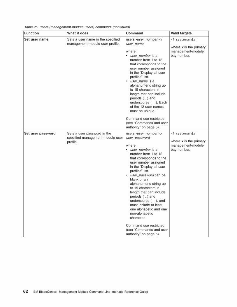
Table 25. users (management-module users) command (continued)
Function What it does Command Valid targets
Set user name Sets a user name in the specified
management-module user profile.
users -user_number -n
user_name
where:
v user_number is a
number from 1 to 12
that corresponds to the
user number assigned
in the “Display all user
profiles” list.
v user_name is a
alphanumeric string up
to 15 characters in
length that can include
periods ( . ) and
underscores ( _ ). Each
of the 12 user names
must be unique.
Command use restricted
(see “Commands and user
authority” on page 5).
-T system:mm[x]
where x is the primary
management-module
bay number.
Set user password Sets a user password in the
specified management-module user
profile.
users -user_number -p
user_password
where:
v user_number is a
number from 1 to 12
that corresponds to the
user number assigned
in the “Display all user
profiles” list.
v user_password can be
blank or an
alphanumeric string up
to 15 characters in
length that can include
periods ( . ) and
underscores ( _ ), and
must include at least
one alphabetic and one
non-alphabetic
character.
Command use restricted
(see “Commands and user
authority” on page 5).
-T system:mm[x]
where x is the primary
management-module
bay number.
62 IBM BladeCenter: Management Module Command-Line Interface Reference Guide

Table 25. users (management-module users) command (continued)
Function What it does Command Valid targets
Set user authority level Sets a user authority level in the
specified management-module user
profile.
users -user_number -a
user_authority
where:
v user_number is a
number from 1 to 12
that corresponds to the
user number assigned
in the “Display all user
profiles” list.
v user_authority is one of
the following:
– operator (read-only)
– rbs (custom)
The custom authority level
parameter is specified
using the following syntax:
rbs:levels:devices
where the levels are one
or more of the following
authority levels, separated
by a vertical bar ( | ):
v super (Supervisor)
v cam (Chassis User
Account Management)
v clm (Chassis Log
Management)
v co (Chassis Operator)
v cc (Chassis
Configuration)
v ca (Chassis
Administration)
v bo (Blade Operator)
v brp (Blade Remote
Present)
v bc (Blade Configuration)
v ba (Blade
Administration)
v so (I/O Module
Operator)
v sc (I/O Module
Configuration)
v sa (I/O Module
Administration)
(continued on next page)
-T system:mm[x]
where x is the primary
management-module
bay number.
Chapter 3. Command reference 63

Table 25. users (management-module users) command (continued)
Function What it does Command Valid targets
Set user authority level
(continued)
where the devices are one
or more of the following
devices, separated by a
vertical bar ( | ). Ranges of
devices are separated by
a dash ( - ).
v cn (Chassis n, where n
is a valid chassis
number. Use c1 for
single-chassis
environments.)
v bn (Blade n, where n is
a valid blade bay
number in the chassis)
v sn (I/O module n, where
n is a valid I/O module
bay number in the
chassis)
Command use restricted
(see “Commands and user
authority” on page 5).
64 IBM BladeCenter: Management Module Command-Line Interface Reference Guide

Table 25. users (management-module users) command (continued)
Function What it does Command Valid targets
Set user authority level
(These are the previous
version of authority levels
that are used only for
backward compatibility
with scripts.)
Sets a user authority level in the
specified management-module user
profile.
users -user_number -a
user_authority
where:
v user_number is a
number from 1 to 12
that corresponds to the
user number assigned
in the “Display all user
profiles” list.
v user_authority is one of
the following:
– ro (read-only)
– super (Supervisor)
– custom
The custom authority level
parameter is specified
using the following syntax:
custom:level1|level2
where the levels are one
or more of the following
authority levels, separated
by a vertical bar ( | ):
v am (User Account
Management Access)
v rca (Blade Server
Remote Console
Access)
v rcvma (Remote Console
and Virtual Media
Access)
v pr (Blade and I/O Power
Restart Access)
v cel (Ability to Clear
Event Logs)
v bc (Basic Configuration
Permission)
v nsc (Network and
Security Configuration
Permission)
v ac (Advanced
Configuration)
Command use restricted
(see “Commands and user
authority” on page 5).
-T system:mm[x]
where x is the primary
management-module
bay number.
Chapter 3. Command reference 65

Table 25. users (management-module users) command (continued)
Function What it does Command Valid targets
Set SNMPv3 user
context name
Sets an SNMPv3 context name in
the specified management-module
user profile.
The context name defines the
context the SNMPv3 user is
working in. A context name can be
shared by multiple users.
users -user_number -cn
context_name
where:
v user_number is a
number from 1 to 12
that corresponds to the
user number assigned
in the “Display all user
profiles” list.
v context_name is a string
up to 31 characters in
length. Each of the 12
context names must be
unique.
Command use restricted
(see “Commands and user
authority” on page 5).
-T system:mm[x]
where x is the primary
management-module
bay number.
Set SNMPv3 user
authentication protocol
Sets the SNMPv3 authentication
protocol to be used for the specified
management-module user profile.
users -user_number -ap
auth_protocol
where:
v user_number is a
number from 1 to 12
that corresponds to the
user number assigned
in the “Display all user
profiles” list.
v auth_protocol is sha,
md5, or blank (no entry)
for none.
Command use restricted
(see “Commands and user
authority” on page 5).
-T system:mm[x]
where x is the primary
management-module
bay number.
Set SNMPv3 user
privacy protocol
Sets the SNMPv3 privacy protocol
to be used for the specified
management-module user profile.
If the privacy protocol is set to
none, no -ppw command option
(privacy password) is required.
users -user_number -pp
privacy_protocol
where:
v user_number is a
number from 1 to 12
that corresponds to the
user number assigned
in the “Display all user
profiles” list.
v privacy_protocol is des
or blank (no entry) for
none.
Command use restricted
(see “Commands and user
authority” on page 5).
-T system:mm[x]
where x is the primary
management-module
bay number.
66 IBM BladeCenter: Management Module Command-Line Interface Reference Guide
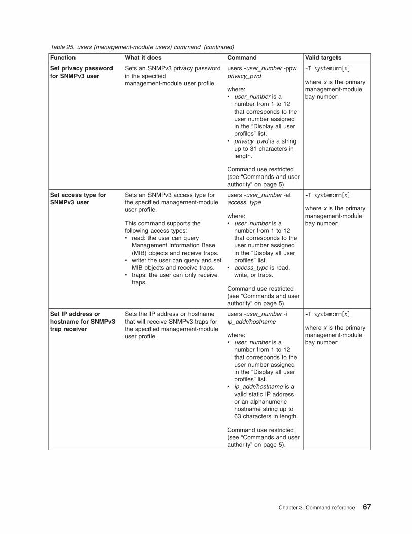
Table 25. users (management-module users) command (continued)
Function What it does Command Valid targets
Set privacy password
for SNMPv3 user
Sets an SNMPv3 privacy password
in the specified
management-module user profile.
users -user_number -ppw
privacy_pwd
where:
v user_number is a
number from 1 to 12
that corresponds to the
user number assigned
in the “Display all user
profiles” list.
v privacy_pwd is a string
up to 31 characters in
length.
Command use restricted
(see “Commands and user
authority” on page 5).
-T system:mm[x]
where x is the primary
management-module
bay number.
Set access type for
SNMPv3 user
Sets an SNMPv3 access type for
the specified management-module
user profile.
This command supports the
following access types:
v read: the user can query
Management Information Base
(MIB) objects and receive traps.
v write: the user can query and set
MIB objects and receive traps.
v traps: the user can only receive
traps.
users -user_number -at
access_type
where:
v user_number is a
number from 1 to 12
that corresponds to the
user number assigned
in the “Display all user
profiles” list.
v access_type is read,
write, or traps.
Command use restricted
(see “Commands and user
authority” on page 5).
-T system:mm[x]
where x is the primary
management-module
bay number.
Set IP address or
hostname for SNMPv3
trap receiver
Sets the IP address or hostname
that will receive SNMPv3 traps for
the specified management-module
user profile.
users -user_number -i
ip_addr/hostname
where:
v user_number is a
number from 1 to 12
that corresponds to the
user number assigned
in the “Display all user
profiles” list.
v ip_addr/hostname is a
valid static IP address
or an alphanumeric
hostname string up to
63 characters in length.
Command use restricted
(see “Commands and user
authority” on page 5).
-T system:mm[x]
where x is the primary
management-module
bay number.
Chapter 3. Command reference 67
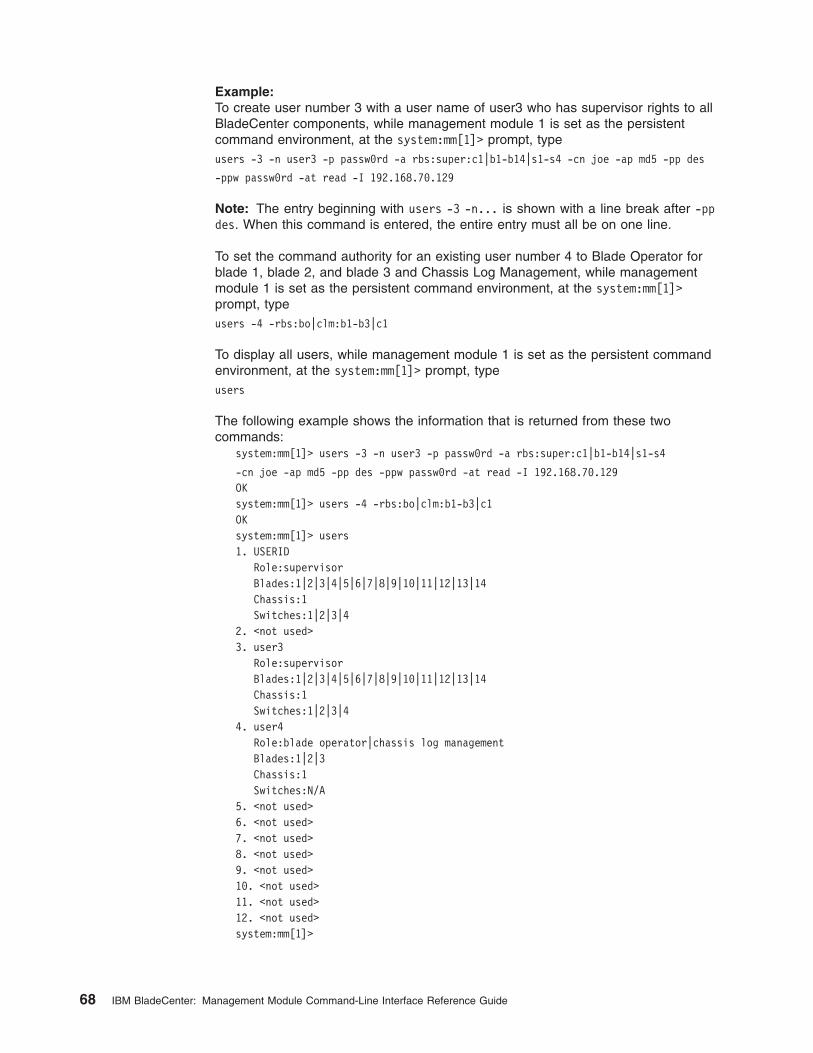
Example:
To create user number 3 with a user name of user3 who has supervisor rights to all
BladeCenter components, while management module 1 is set as the persistent
command environment, at the system:mm[1]> prompt, type
users -3 -n user3 -p passw0rd -a rbs:super:c1|b1-b14|s1-s4 -cn joe -ap md5 -pp des
-ppw passw0rd -at read -I 192.168.70.129
Note: The entry beginning with users -3 -n... is shown with a line break after -pp
des. When this command is entered, the entire entry must all be on one line.
To set the command authority for an existing user number 4 to Blade Operator for
blade 1, blade 2, and blade 3 and Chassis Log Management, while management
module 1 is set as the persistent command environment, at the system:mm[1]>
prompt, type
users -4 -rbs:bo|clm:b1-b3|c1
To display all users, while management module 1 is set as the persistent command
environment, at the system:mm[1]> prompt, type
users
The following example shows the information that is returned from these two
commands:
system:mm[1]> users -3 -n user3 -p passw0rd -a rbs:super:c1|b1-b14|s1-s4
-cn joe -ap md5 -pp des -ppw passw0rd -at read -I 192.168.70.129
OK
system:mm[1]> users -4 -rbs:bo|clm:b1-b3|c1
OK
system:mm[1]> users
1. USERID
Role:supervisor
Blades:1|2|3|4|5|6|7|8|9|10|11|12|13|14
Chassis:1
Switches:1|2|3|4
2. <not used>
3. user3
Role:supervisor
Blades:1|2|3|4|5|6|7|8|9|10|11|12|13|14
Chassis:1
Switches:1|2|3|4
4. user4
Role:blade operator|chassis log management
Blades:1|2|3
Chassis:1
Switches:N/A
5. <not used>
6. <not used>
7. <not used>
8. <not used>
9. <not used>
10. <not used>
11. <not used>
12. <not used>
system:mm[1]>
68 IBM BladeCenter: Management Module Command-Line Interface Reference Guide
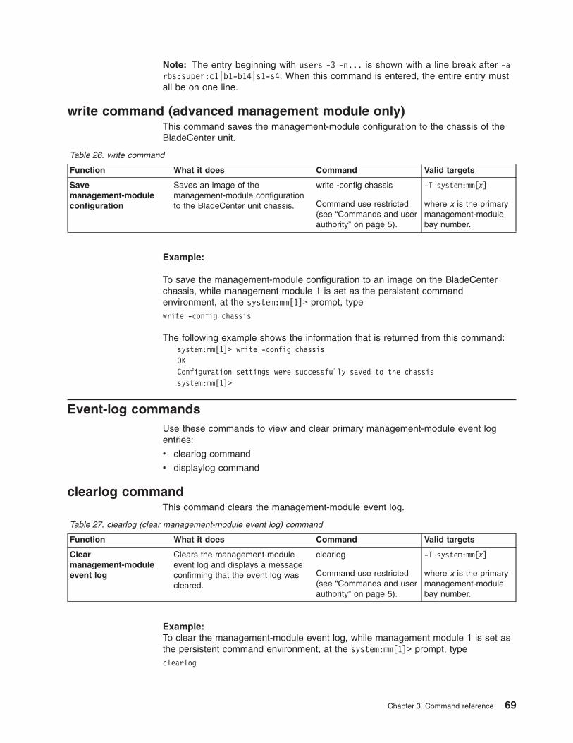
Note: The entry beginning with users -3 -n... is shown with a line break after -a
rbs:super:c1|b1-b14|s1-s4. When this command is entered, the entire entry must
all be on one line.
write command (advanced management module only)
This command saves the management-module configuration to the chassis of the
BladeCenter unit.
Table 26. write command
Function What it does Command Valid targets
Save
management-module
configuration
Saves an image of the
management-module configuration
to the BladeCenter unit chassis.
write -config chassis
Command use restricted
(see “Commands and user
authority” on page 5).
-T system:mm[x]
where x is the primary
management-module
bay number.
Example:
To save the management-module configuration to an image on the BladeCenter
chassis, while management module 1 is set as the persistent command
environment, at the system:mm[1]> prompt, type
write -config chassis
The following example shows the information that is returned from this command:
system:mm[1]> write -config chassis
OK
Configuration settings were successfully saved to the chassis
system:mm[1]>
Event-log commands
Use these commands to view and clear primary management-module event log
entries:
v clearlog command
v displaylog command
clearlog command
This command clears the management-module event log.
Table 27. clearlog (clear management-module event log) command
Function What it does Command Valid targets
Clear
management-module
event log
Clears the management-module
event log and displays a message
confirming that the event log was
cleared.
clearlog
Command use restricted
(see “Commands and user
authority” on page 5).
-T system:mm[x]
where x is the primary
management-module
bay number.
Example:
To clear the management-module event log, while management module 1 is set as
the persistent command environment, at the system:mm[1]> prompt, type
clearlog
Chapter 3. Command reference 69

The following example shows the information that is returned:
system:mm[1]> clearlog
OK
system:mm[1]>
displaylog command
This command displays management-module event log entries.
Table 28. displaylog (display management-module event log) command
Function What it does Command Valid targets
Display
management-module
event log entries
Displays five entries from the
management-module event log. The
first time the command is executed,
the five most recent log entries are
displayed. Each subsequent time
the command is issued, the next
five entries in the log display.
displaylog -T system:mm[x]
where x is the primary
management-module
bay number.
Display
management-module
event log entries (reset
counter)
Resets the counter and displays the
first five entries in the
management-module event log.
displaylog -f -T system:mm[x]
where x is the primary
management-module
bay number.
Example:
To display the first five primary management-module event log entries, while
management module 1 is set as the persistent command environment, at the
system:mm[1]> prompt, type
displaylog -f
To display the next five management-module event log entries, type (a second time)
displaylog
To display the next five management-module event log entries, type
displaylog
The following example shows the information that is returned from these three
commands:
system:mm[1]> displaylog -f
1 I SERVPROC 10/27/03 19:45:57 Remote
Login Successful. Login ID:’’USERID’ CLI authenticated from
192.168.70.231 (Telnet).’
2 E SERVPROC 10/27/03 19:42:58 Failure
reading I2C device. Check devices on bus 4.
3 E SERVPROC 10/27/03 19:42:58 Failure
reading I2C device. Check devices on bus 3.
4 E SERVPROC 10/27/03 19:42:58 Failure
reading I2C device. Check devices on bus 2.
5 I SERVPROC 10/27/03 19:41:54 Remote
Login Successful. Login ID:’’USERID’ from WEB browser at
IP@=192.168.70.231’
system:mm[1]> displaylog
6 E SERVPROC 10/27/03 19:41:53 Blower 2
Fault Multiple blower failures
70 IBM BladeCenter: Management Module Command-Line Interface Reference Guide

7 E SERVPROC 10/27/03 19:41:53 Blower 1
Fault Single blower failure
8 I SERVPROC 10/27/03 19:41:48
Ethernet[1] Link Established at 100Mb, Full Duplex.
9 I SERVPROC 10/27/03 19:41:48
Ethernet[1] configured to do 100Mb/Full Duplex.
10 I SERVPROC 10/27/03 19:41:48
Ethernet[1] MAC Address currently being used: 0x00-09-6B-CA-0C-81
system:mm[1]> displaylog
11 I SERVPROC 10/27/03 19:41:48
Ethernet[0] Link Established at 100Mb, Full Duplex.
12 I SERVPROC 10/27/03 19:41:48
Ethernet[0] configured to do Auto Speed/Auto Duplex.
13 I SERVPROC 10/27/03 19:41:48
Ethernet[0] MAC Address currently being used: 0x00-09-6B-CA-0C-80
14 I SERVPROC 10/27/03 19:41:48
Management Module Network Initialization Complete.
15 I SERVPROC 10/27/03 19:41:46 ENET[1]
IP-Cfg:HstName=MM00096BCA0C81, IP@=192.168.70.126 ,GW@=0.0.0.0,
NetMsk=255.255.255.0
system:mm[1]>
The following example shows the information that is returned if the displaylog
command is run after the event log is cleared:
system:mm[1]> displaylog -f
1 I SERVPROC 10/27/03 19:53:02 System
log cleared.
(There are no more entries in the event log.)
system:mm[1]>
Power-control commands
Use these commands to control operation of the BladeCenter unit, blade servers,
and I/O (switch) modules:
v boot command
v fuelg command
v power command
v reset command
boot command
This command resets blade servers with several different restart options.
Table 29. boot command
Function What it does Command Valid targets
Reset blade server Performs an immediate reset and
restart of the specified blade server.
This command will start a blade
server that is turned off.
boot
Command use restricted
(see “Commands and user
authority” on page 5).
-T system:blade[x]
where x is the blade
server bay number.
Chapter 3. Command reference 71

Table 29. boot command (continued)
Function What it does Command Valid targets
Reset blade server to
command console
Resets the specified blade server,
causing it to open a command
console with an SOL session when
it restarts.
This command will start a blade
server that is turned off.
boot -c
Command use restricted
(see “Commands and user
authority” on page 5).
-T system:blade[x]
where x is the blade
server bay number.
Power cycle Cycles power for the specified
blade server. If the blade server is
off, it will turn on. If the blade server
is on, it will turn off and then turn
on.
boot -p powercycle
Command use restricted
(see “Commands and user
authority” on page 5).
-T system:blade[x]
where x is the blade
server bay number.
Reset blade server Performs an immediate reset and
restart of the specified blade server.
This command will start a blade
server that is turned off.
boot -p reset
Command use restricted
(see “Commands and user
authority” on page 5).
-T system:blade[x]
where x is the blade
server bay number.
Example:
To boot the blade server in blade bay 3, while management module 1 is set as the
persistent command environment, at the system:mm[1]> prompt, type
boot -T system:blade[3]
The following example shows the information that is returned:
system:mm[1]> boot -T system:blade[3]
OK
system:mm[1]>
fuelg command
This command displays power domain information, listing the power modules that
are installed in the BladeCenter unit and information about how the power in each
domain is used. This command also configures the power domain policies for
oversubscription and quiet mode
Table 30. fuelg command
Function What it does Command Valid targets
Display power domain
status overview
Displays health status and total
power usage information for all
power domains
fuelg -T system
Display detailed power
domain status
Displays detailed status and usage
information for the specified power
domains
fuelg domain
where domain is “pd1” for
power domain 1 and “pd2”
for power domain 2. If no
domain is specified, a
status overview for all
power domains displays.
-T system
72 IBM BladeCenter: Management Module Command-Line Interface Reference Guide

Table 30. fuelg command (continued)
Function What it does Command Valid targets
Set power domain
redundancy loss policy
Sets how the BladeCenter unit
responds to a condition that could
cause a loss of redundant power.
fuelg domain -os policy
where:
v domain is “pd1” for
power domain 1 and
“pd2” for power domain
2. If no domain is
specified, the policy is
applied to all power
domains.
v policy of:
– “none” (default)
allows loss of
redundancy.
– “nonrecov” prevents
components from
turning on that will
cause loss of power
redundancy.
– “recov” power
throttles components
to maintain power
redundancy and
prevents components
from turning on that
will cause loss of
power redundancy.
Command use restricted
(see “Commands and user
authority” on page 5).
-T system
Thermal event response
(quiet mode)
Sets how the BladeCenter unit
blowers respond to thermal events.
fuelg -qm setting
where the quiet-mode
setting of:
v “off” (default) allows
blowers to increase
speed to provide
additional cooling.
v “on” keeps blowers at a
fixed speed and power
throttles BladeCenter
components to reduce
power consumption
(only for BladeCenter
components that
support power
throttling).
Command use restricted
(see “Commands and user
authority” on page 5).
-T system
Example:
To view a power domain status overview, while the BladeCenter unit is set as the
persistent command environment, at the system> prompt, type
fuelg
Chapter 3. Command reference 73

To turn on quiet mode for all power domains, while the BladeCenter unit is set as
the persistent command environment, at the system> prompt, type
fuelg -qm on
To view the detailed power domain status for power domain 1, while the
BladeCenter unit is set as the persistent command environment, at the system>
prompt, type
fuelg pd1
The following example shows the information that is returned when the fuelg
command is run on a management module. Results that are returned for other
management modules, such as an advanced management module, might have
different categories and values.
system> fuelg
Note: All power values are displayed in Watts.
Power Domain 1
--------------
Status: Power domain status is good.
Modules:
Bay 1: 2000
Bay 2: 2000
Power Budget: 3200
Reserved Power: 400
Remaining Power: 2800
Power in Use: 400
Power Domain 2
--------------
Status: Power domain status is good.
Modules:
Bay 3: 1800
Bay 4: 1800
Power Budget: 2880
Reserved Power: 0
Remaining Power: 2880
Power in Use: 0
-qm off
system> fuelg -qm on
OK
system> fuelg pd1
Power -- Allocated Power --
Bay(s) Module State Current Max Min
====== =================== ===== ======= ===== =====
Chassis Components
Midplane On 10 10 10
no media tray
Blowers
1 Blower 1 (NP) On 120 120 120
2 Blower 2 (NP) On 120 120 120
Management Modules
1 WMN315619689 On 25 25 25
2 Backup MM (NP) 25 25 25
I/O Modules
1 I/O Module 2 (NP) 45 45 45
74 IBM BladeCenter: Management Module Command-Line Interface Reference Guide

2 I/O Module 2 (NP) 45 45 45
Domain totals:
Allocated Power 390 390 390
Note: (T) means "throttled", (U) means "unable to power up",
* means "the blade may throttle", (NP) means "the module is not
present", (D) means "discovering", (C) means "comm error", SB
means "Standby"
-os none
system>
power command
This command turns on and turns off blade servers and I/O (switch) modules.
Table 31. power command
Function What it does Command Valid targets
Power on Turns on the specified blade server
or I/O (switch) module.
power -on
Command use restricted
(see “Commands and user
authority” on page 5).
-T system:blade[x]
-T system:switch[x]
where x is the blade
server or I/O (switch)
module bay number.
Power on to command
console
Opens a command console with an
SOL session when the specified
blade server is turned on.
power -on -c
Command use restricted
(see “Commands and user
authority” on page 5).
-T system:blade[x]
where x is the blade
server bay number.
Power off Turns off the specified blade server
or I/O (switch) module.
power -off
Command use restricted
(see “Commands and user
authority” on page 5).
-T system:blade[x]
-T system:switch[x]
where x is the blade
server or I/O (switch)
module bay number.
Power cycle Cycles power for the specified
blade server or I/O (switch) module.
If the blade server or I/O (switch)
module is off, it will turn on. If the
blade server or I/O (switch) module
is on, it will turn off and then turn
on.
power -cycle
Command use restricted
(see “Commands and user
authority” on page 5).
-T system:blade[x]
-T system:switch[x]
where x is the blade
server or I/O (switch)
module bay number.
Power cycle to
command console
Cycles power for the specified
blade server. If the blade server is
off, it opens a command console
with an SOL session when it is
turned on. If the blade server is on,
it will turn off and then turn on.
power -cycle -c
Command use restricted
(see “Commands and user
authority” on page 5).
-T system:blade[x]
where x is the blade
server bay number.
Display power state Displays the current power state for
the specified blade server or I/O
(switch) module. Possible return
values are on and off.
power -state -T system:blade[x]
-T system:switch[x]
where x is the blade
server or I/O (switch)
module bay number.
Chapter 3. Command reference 75

Table 31. power command (continued)
Function What it does Command Valid targets
Display POST status for
I/O (switch) module
Displays the POST status for the
specified I/O (switch) module. If the
command is run while POST is in
progress, it returns the level of
POST that is currently in process. If
the command is run after POST is
complete, it displays one of the
following return values:
v The POST results could not be
read. message displays if there
was an internal error during
POST.
v The POST results not complete:
hex_code message displays if
POST results are not available
after POST completes.
v If POST returns valid results, one
of the following messages
displays:
– hex_code: Base internal
function failure detected.
– hex_code: Internal
interface failure detected.
– hex_code: External
interface failure detected.
– hex_code: Module completed
POST successfully.
– hex_code: Cannot decode
POST result code.v The Invalid POST results.
message displays if none of the
above conditions is true.
Where hex_code is a hexadecimal
code. See the documentation that
comes with your I/O module for
information.
Note: This command option is not
supported for serial concentrator I/O
(switch) modules.
power -state -post -T system:switch[x]
where x is the I/O
(switch) module bay
number.
Example:
To display the power state for the blade server in blade bay 5, while this blade
server is set as the persistent command environment, at the system:blade[5]>
prompt, type
power -state
To turn on the blade server in blade bay 5, while this blade server is set as the
persistent command environment, at the system:blade[5]> prompt, type
power -on
76 IBM BladeCenter: Management Module Command-Line Interface Reference Guide

To display the power state for the blade server in blade bay 5 again, while this
blade server is set as the persistent command environment, at the
system:blade[5]> prompt, type
power -state
The following example shows the information that is returned from these three
commands:
system:blade[5]> power -state
Off
system:blade[5]> power -on
OK
system:blade[5]> power -state
On
system:blade[5]>
reset command
This command resets blade servers, blade server integrated system management
processors (service processors), I/O (switch) modules, or the primary management
module.
Table 32. reset command
Function What it does Command Valid targets
Reset Performs an immediate reset and
restart of the specified device.
reset
Command use restricted
(see “Commands and user
authority” on page 5).
-T system:blade[x]
-T system:switch[x]
-T system:blade[x]:sp
-T system:mm[x]
where x is the blade
server, I/O (switch)
module, or primary
management-module
bay number.
Reset blade server to
command console
Opens a command console with an
SOL session when the specified
blade server is reset.
reset -c
Command use restricted
(see “Commands and user
authority” on page 5).
-T system:blade[x]
-T system:blade[x]:sp
where x is the blade
server bay number.
Reset management
module with failover
Resets the primary management
module, enabling failover if a
redundant management module is
present. An error message is
displayed if you try to enable
failover when a redundant
management module is not
installed.
reset -f
Command use restricted
(see “Commands and user
authority” on page 5).
-T system:mm[x]
where x is the primary
management-module
bay number.
Reset I/O (switch)
module with standard
diagnostics
Performs an immediate reset and
restart of the specified device,
running standard diagnostics on the
I/O (switch) module after it restarts.
Running the reset -std command
gives the same result as running
the reset command on a I/O
(switch) module.
reset -std
Command use restricted
(see “Commands and user
authority” on page 5).
-T system:switch[x]
where x is the I/O
(switch) module bay
number.
Chapter 3. Command reference 77
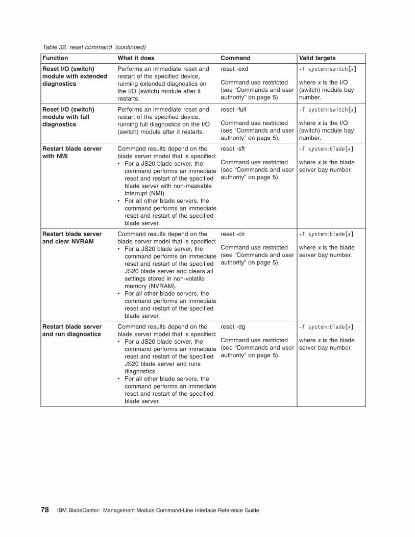
Table 32. reset command (continued)
Function What it does Command Valid targets
Reset I/O (switch)
module with extended
diagnostics
Performs an immediate reset and
restart of the specified device,
running extended diagnostics on
the I/O (switch) module after it
restarts.
reset -exd
Command use restricted
(see “Commands and user
authority” on page 5).
-T system:switch[x]
where x is the I/O
(switch) module bay
number.
Reset I/O (switch)
module with full
diagnostics
Performs an immediate reset and
restart of the specified device,
running full diagnostics on the I/O
(switch) module after it restarts.
reset -full
Command use restricted
(see “Commands and user
authority” on page 5).
-T system:switch[x]
where x is the I/O
(switch) module bay
number.
Restart blade server
with NMI
Command results depend on the
blade server model that is specified:
v For a JS20 blade server, the
command performs an immediate
reset and restart of the specified
blade server with non-maskable
interrupt (NMI).
v For all other blade servers, the
command performs an immediate
reset and restart of the specified
blade server.
reset -sft
Command use restricted
(see “Commands and user
authority” on page 5).
-T system:blade[x]
where x is the blade
server bay number.
Restart blade server
and clear NVRAM
Command results depend on the
blade server model that is specified:
v For a JS20 blade server, the
command performs an immediate
reset and restart of the specified
JS20 blade server and clears all
settings stored in non-volatile
memory (NVRAM).
v For all other blade servers, the
command performs an immediate
reset and restart of the specified
blade server.
reset -clr
Command use restricted
(see “Commands and user
authority” on page 5).
-T system:blade[x]
where x is the blade
server bay number.
Restart blade server
and run diagnostics
Command results depend on the
blade server model that is specified:
v For a JS20 blade server, the
command performs an immediate
reset and restart of the specified
JS20 blade server and runs
diagnostics.
v For all other blade servers, the
command performs an immediate
reset and restart of the specified
blade server.
reset -dg
Command use restricted
(see “Commands and user
authority” on page 5).
-T system:blade[x]
where x is the blade
server bay number.
78 IBM BladeCenter: Management Module Command-Line Interface Reference Guide

Table 32. reset command (continued)
Function What it does Command Valid targets
Restart blade server
and run diagnostics
using default boot
sequence
Command results depend on the
blade server model that is specified:
v For a JS20 blade server, the
command performs an immediate
reset and restart of the specified
JS20 blade server and runs
diagnostics using the default boot
sequence configured for the
blade server.
v For all other blade servers, the
command performs an immediate
reset and restart of the specified
blade server.
reset -ddg
Command use restricted
(see “Commands and user
authority” on page 5).
-T system:blade[x]
where x is the blade
server bay number.
Example:
To reset the service processor on the blade server in blade bay 5, while the
BladeCenter unit is set as the persistent command environment, at the system>
prompt, type
reset
The following example shows the information that is returned:
system> reset -T blade[5]:sp
OK
system>
Session commands
Use these commands to start an SOL connection to the command console of a
specific blade server or to end a command console session:
v console command
v exit command
console command
This command sets up a serial over LAN connection to the command console of a
blade server.
To end an SOL session, press Esc followed by an open parenthesis:
Esc (
Table 33. console command
Function What it does Command Valid targets
Create SOL session
with blade server
Creates an SOL connection to the
specified blade server.
console
Command use restricted
(see “Commands and user
authority” on page 5).
-T system:blade[x]
where x is the blade
server bay number.
Chapter 3. Command reference 79
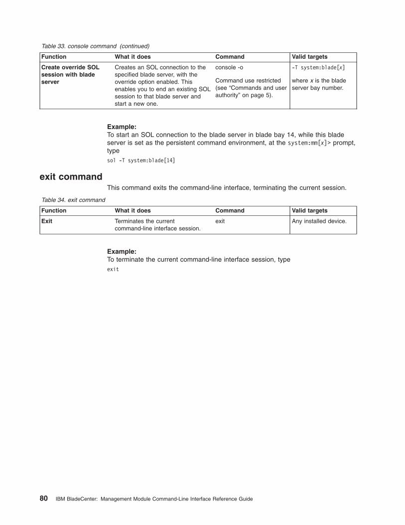
Table 33. console command (continued)
Function What it does Command Valid targets
Create override SOL
session with blade
server
Creates an SOL connection to the
specified blade server, with the
override option enabled. This
enables you to end an existing SOL
session to that blade server and
start a new one.
console -o
Command use restricted
(see “Commands and user
authority” on page 5).
-T system:blade[x]
where x is the blade
server bay number.
Example:
To start an SOL connection to the blade server in blade bay 14, while this blade
server is set as the persistent command environment, at the system:mm[x]> prompt,
type
sol -T system:blade[14]
exit command
This command exits the command-line interface, terminating the current session.
Table 34. exit command
Function What it does Command Valid targets
Exit Terminates the current
command-line interface session.
exit Any installed device.
Example:
To terminate the current command-line interface session, type
exit
80 IBM BladeCenter: Management Module Command-Line Interface Reference Guide

System management commands (for BladeCenter T only)
Use these commands to manage alarms for monitored parameters of the
BladeCenter T unit:
v alarm command
alarm command
This command displays alarm information, acknowledges alarms, and clears alarms
for the specified command target.
Table 35. alarm command
Function What it does Command Valid targets
Display all alarms Display all alerts generated by the
target component. When directed to
the BladeCenter unit, the command
returns a summary of alarms for all
BladeCenter components. When
directed to a component installed in
the BladeCenter unit, the command
returns a detailed alarm listing for
that component.
Detailed alarm listings include an
alarm key that can be used to
acknowledge or clear an alarm.
alarm -T system
-T system:mm[x]
-T system:blade[x]
-T system:switch[x]
-T system:power[x]
-T system:blower[x]
where x is the primary
management-module,
blade server, I/O
(switch) module, power
module, or blower bay
number.
Display power alarms Display all power related alerts
generated by the target component.
When directed to the BladeCenter
unit, the command returns a
summary of alarms for all
BladeCenter components. When
directed to a component installed in
the BladeCenter unit, the command
returns a detailed alarm listing for
that component.
Detailed alarm listings include an
alarm key that can be used to
acknowledge or clear an alarm.
alarm -p -T system
-T system:mm[x]
-T system:blade[x]
-T system:switch[x]
-T system:power[x]
-T system:blower[x]
where x is the primary
management-module,
blade server, I/O
(switch) module, power
module, or blower bay
number.
Display alarm
information (specified
by alarm generator ID)
Display information for alarm
specified by the generator ID.
alarm -q -g value
where value is the
generator ID.
Command use restricted
(see “Commands and user
authority” on page 5).
-T system:mm[x]
-T system:blade[x]
-T system:switch[x]
-T system:power[x]
-T system:blower[x]
where x is the primary
management-module,
blade server, I/O
(switch) module, power
module, or blower bay
number.
Chapter 3. Command reference 81

Table 35. alarm command (continued)
Function What it does Command Valid targets
Display alarm
information (specified
by alarm ID)
Display information for alarm
specified by the alarm ID.
alarm -q -a value
where value is the alarm
ID.
-T system:mm[x]
-T system:blade[x]
-T system:switch[x]
-T system:power[x]
-T system:blower[x]
where x is the primary
management-module,
blade server, I/O
(switch) module, power
module, or blower bay
number.
Display detailed alarm
information (specified
by generator
information)
Display detailed information for
alarm specified by the alarm
generator information. Information
returned includes the alarm
description that is shown by the
management-module Web interface
and other information such as the
alarm severity, power source,
software indicator, and an alarm
key.
alarm -q -o value
where value is the
generator information.
-T system:mm[x]
-T system:blade[x]
-T system:switch[x]
-T system:power[x]
-T system:blower[x]
where x is the primary
management-module,
blade server, I/O
(switch) module, power
module, or blower bay
number.
Display alarm
information (specified
by complete alarm key)
Display information for alarm
specified by the complete alarm
key.
alarm -q -k m:g:o:a
where m:g:o:a is the
complete alarm key:
v m is the module ID
v g is the generator ID
v o is the generator
information
v a is the alarm ID
-T system:mm[x]
-T system:blade[x]
-T system:switch[x]
-T system:power[x]
-T system:blower[x]
where x is the primary
management-module,
blade server, I/O
(switch) module, power
module, or blower bay
number.
Acknowledge alarm
(specified by alarm
generator ID)
Acknowledge the alarm specified by
the generator ID.
alarm -r -g value
where value is the
generator ID.
Command use restricted
(see “Commands and user
authority” on page 5).
-T system:mm[x]
-T system:blade[x]
-T system:switch[x]
-T system:power[x]
-T system:blower[x]
where x is the primary
management-module,
blade server, I/O
(switch) module, power
module, or blower bay
number.
82 IBM BladeCenter: Management Module Command-Line Interface Reference Guide

Table 35. alarm command (continued)
Function What it does Command Valid targets
Acknowledge alarm
(specified by generator
information)
Acknowledge the alarm specified by
the generator information.
alarm -r -o value
where value is the
generator information.
Command use restricted
(see “Commands and user
authority” on page 5).
-T system:mm[x]
-T system:blade[x]
-T system:switch[x]
-T system:power[x]
-T system:blower[x]
where x is the primary
management-module,
blade server, I/O
(switch) module, power
module, or blower bay
number.
Acknowledge alarm
(specified by alarm ID)
Acknowledge the alarm specified by
the alarm ID.
alarm -r -a value
where value is the alarm
ID.
Command use restricted
(see “Commands and user
authority” on page 5).
-T system:mm[x]
-T system:blade[x]
-T system:switch[x]
-T system:power[x]
-T system:blower[x]
where x is the primary
management-module,
blade server, I/O
(switch) module, power
module, or blower bay
number.
Acknowledge alarm
(specified by complete
alarm key)
Acknowledge the alarm specified by
the complete alarm key.
alarm -r -k m:g:o:a
where m:g:o:a is the
complete alarm key:
v m is the module ID
v g is the generator ID
v o is the generator
information
v a is the alarm ID
Command use restricted
(see “Commands and user
authority” on page 5).
-T system:mm[x]
-T system:blade[x]
-T system:switch[x]
-T system:power[x]
-T system:blower[x]
where x is the primary
management-module,
blade server, I/O
(switch) module, power
module, or blower bay
number.
Clear alarm (specified
by alarm generator ID)
Clear the alarm specified by the
generator ID.
alarm -c -g value
where value is the
generator ID.
Command use restricted
(see “Commands and user
authority” on page 5).
-T system:mm[x]
-T system:blade[x]
-T system:switch[x]
-T system:power[x]
-T system:blower[x]
where x is the primary
management-module,
blade server, I/O
(switch) module, power
module, or blower bay
number.
Chapter 3. Command reference 83
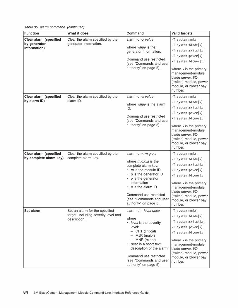
Table 35. alarm command (continued)
Function What it does Command Valid targets
Clear alarm (specified
by generator
information)
Clear the alarm specified by the
generator information.
alarm -c -o value
where value is the
generator information.
Command use restricted
(see “Commands and user
authority” on page 5).
-T system:mm[x]
-T system:blade[x]
-T system:switch[x]
-T system:power[x]
-T system:blower[x]
where x is the primary
management-module,
blade server, I/O
(switch) module, power
module, or blower bay
number.
Clear alarm (specified
by alarm ID)
Clear the alarm specified by the
alarm ID.
alarm -c -a value
where value is the alarm
ID.
Command use restricted
(see “Commands and user
authority” on page 5).
-T system:mm[x]
-T system:blade[x]
-T system:switch[x]
-T system:power[x]
-T system:blower[x]
where x is the primary
management-module,
blade server, I/O
(switch) module, power
module, or blower bay
number.
Clear alarm (specified
by complete alarm key)
Clear the alarm specified by the
complete alarm key.
alarm -c -k m:g:o:a
where m:g:o:a is the
complete alarm key:
v m is the module ID
v g is the generator ID
v o is the generator
information
v a is the alarm ID
Command use restricted
(see “Commands and user
authority” on page 5).
-T system:mm[x]
-T system:blade[x]
-T system:switch[x]
-T system:power[x]
-T system:blower[x]
where x is the primary
management-module,
blade server, I/O
(switch) module, power
module, or blower bay
number.
Set alarm Set an alarm for the specified
target, including severity level and
description.
alarm -s -l level desc
where
v level is the severity
level:
– CRT (critical)
– MJR (major)
– MNR (minor)v desc is a short text
description of the alarm
Command use restricted
(see “Commands and user
authority” on page 5).
-T system:mm[x]
-T system:blade[x]
-T system:switch[x]
-T system:power[x]
-T system:blower[x]
where x is the primary
management-module,
blade server, I/O
(switch) module, power
module, or blower bay
number.
84 IBM BladeCenter: Management Module Command-Line Interface Reference Guide

Example:
To display the alarm status for the BladeCenter T unit, while the BladeCenter T unit
is set as the persistent command environment, at the system> prompt, type
alarm
To display the power alarm status for the BladeCenter T unit, while the BladeCenter
T unit is set as the persistent command environment, at the system> prompt, type
alarm -p
To display detailed power alarm status for the power module in power bay 2, while
the BladeCenter T unit is set as the persistent command environment, at the
system> prompt, type
alarm -T system:power[2]
The following example shows the information that is returned from a series of alarm
commands. This example assumes that the blade server in blade bay 3 has a
major over-temperature fault and that the power module in power bay 2 has a
critical fault.
system> alarm
Alarms Summary List
Module Severity Power S/W
power[2] CRT Yes No
blade[3] MJR No No
system> alarm -p
Alarms Summary List
Module Severity Power S/W
power[2] CRT Yes No
system> alarm -T system:power[2]
Alarms Detailed List
Severity Power S/W Description Key
CRT Yes No Under Voltage 2:1:3:2
system> alarm -c -k 2:1:3:2 -T system:power[2]
Alarm Cleared
system> alarm -T system:power[2]
No Active Alarms
system> alarm
Alarms Summary List
Module Severity Power S/W
blade[3] MJR No No
system> alarm -T system:blade[3]
Alarms Detailed List
Severity Power S/W Description Key
MJR No No Over temperature 3:3:1:3
system> alarm -s -l CRT
OK
system> alarm -s -l MNR -p Investigate Watts -T system:blade[2]
OK
system> alarm -s -l CRT -p Under Voltage -T system:blade[2]
Failed. AlarmID is being used
system>
Chapter 3. Command reference 85

86 IBM BladeCenter: Management Module Command-Line Interface Reference Guide

Chapter 4. Error messages
The command-line interface provides error messages specific to each command.
The following topics list the common error messages that apply to all commands
and command-specific error messages, along with their definitions.
v “Common errors” on page 88
v “alarm command errors” on page 89
v “alertentries command errors” on page 90
v “boot command errors” on page 90
v “clear command errors” on page 90
v “clearlog command errors” on page 91
v “console command errors” on page 91
v “dhcpinfo command errors” on page 91
v “displaylog command errors” on page 91
v “displaysd command errors” on page 92
v “dns command errors” on page 92
v “fuelg command errors” on page 92
v “health command errors” on page 93
v “identify command errors” on page 93
v “ifconfig command errors” on page 93
v “info command errors” on page 95
v “list command errors” on page 96
v “power command errors” on page 96
v “portcfg command errors” on page 96
v “read command errors” on page 96
v “reset command errors” on page 97
v “service command errors” on page 97
v “smtp command errors” on page 97
v “snmp command errors” on page 97
v “sol command errors” on page 98
v “tcpcmdmode command errors” on page 99
v “telnetcfg command errors” on page 100
v “update command errors” on page 100
v “uplink command errors” on page 102
v “users command errors” on page 102
v “write command errors” on page 105
© Copyright IBM Corp. 2006 87

Common errors
The following table lists error messages that apply to all commands. Each
command that has unique errors will also have a list of command-specific error
messages.
Table 36. Common errors
Error message Definition
Command line contains extraneous arguments Displays when extra command arguments are entered.
Duplicate option: option
where option identifies the command option that was
entered more than once.
Displays when a user tries to enter the same command
option in a single command multiple times. For example,
dns -i 192.168.70.29 -i
Each option can only be used once per command. Displays when a user tries to enter the same command
option in a single command multiple times. For example,
env -T system:blade[4] -T system:blade[5].
Error writing data for option option
where option identifies the command option that is
returning an error.
Displays when an internal error occurs while writing a
command option value.
Illegal option: option
where option identifies the illegal short command option
that was entered.
Displays when an illegal short command option is
entered.
Integer argument out of range (range - range) for option:
argument
where:
v range identifies the range limits
v option identifies the command option
v argument identifies the integer that is out of range
Displays when an integer is entered that is out of range.
Invalid integer argument for option: argument
where:
v option identifies the command option
v argument identifies the invalid argument
Displays when an invalid integer is entered.
Invalid option Displays when an invalid command option is entered.
Invalid option argument for option: argument
where:
v option identifies the command option
v argument identifies the invalid argument
Displays when an invalid argument for a command option
is entered.
Invalid target path Displays when a user tries to issue a command to a
target that is not valid.
Long option option requires an argument
where option identifies the long command option that is
missing an argument.
Displays when a long command option is entered without
a required argument.
Missing option name Displays when a dash (-) is entered with out a command
option name.
Read/write command error Displays when an internal error occurs while executing
the command.
88 IBM BladeCenter: Management Module Command-Line Interface Reference Guide

Table 36. Common errors (continued)
Error message Definition
Short option option requires an argument
where option identifies the short command option that is
missing an argument.
Displays when a short command option is entered without
a required argument.
The target bay is empty. Displays when the user tries to issue a command to an
empty blade bay, blower bay, I/O-module bay,
management-module bay, or power bay.
The target bay is out of range. Displays when a user tries to issue a command to a
target that is out of range for that target. For example, the
env -T system:blade[15] command is out of range
because the BladeCenter unit has only 14 blade bays.
Unrecognized long option: option
where option identifies the illegal long command option
that was entered.
Displays when an illegal long command option is entered.
User does not have the authority to issue this command Displays when a user lacks the authority level necessary
to execute a command.
alarm command errors
The following table lists error messages for the alarm command. See “Common
errors” on page 88 for a list of error messages that apply to all commands.
Table 37. alarm command errors
Error message Definition
Alarm Description must be provided for setting an alarm. Displays when the user tries to set an alarm without
providing an alarm description.
Alarm ID must be from 1 to 255. Displays when an invalid alarm ID is entered.
Generator ID must be from 1 to 255. Displays when an invalid generator ID is entered.
Generator ID must be provided. Displays when a generator information ID is provided
without a generator ID.
Module ID must be from 1 to 255. Displays when an invalid module ID is entered.
No active alarm. Displays when no active alarm is found for the command
target.
No matching alarm. Displays when no matching alarm is found for the
command target.
Severity level must be provided for setting an alarm. Displays when the user tries to set an alarm without
specifying the severity level.
Software Generator ID must be from 1 to 255. Displays when an invalid generator information is entered.
The entered Alarm Key is not in proper format. Displays when an invalid alarm key is entered.
Unable to acknowledge the requested alarm. Displays when an internal error occurs while
acknowledging an alarm.
Unable to clear the requested alarm. Displays when an internal error occurs while clearing an
alarm.
Unable to set the requested alarm. Displays when an internal error occurs while setting an
alarm.
Chapter 4. Error messages 89

alertentries command errors
The following table lists error messages for the alertentries command. See
“Common errors” on page 88 for a list of error messages that apply to all
commands.
Table 38. alertentries command errors
Error message Definition
An entry cannot be modified and deleted in the same
command.
Displays when a user tries to modify an entry and delete
it in the same command.
Arguments containing spaces must be enclosed in
quotation marks.
Displays when a user tries to enter a string containing
spaces that has an opening quotation mark without a
closing quotation mark.
Invalid input. Angle brackets are not allowed in the name
field.
Displays when a user tries to enter a string parameter
containing < or > for the -n (name) command option.
Invalid option Displays when an invalid command option is entered.
This includes numeric options for the alert recipient that
are not from 1 through 12.
Invalid parameter. Input must be numeric. Displays when a user tries to enter a parameter value
containing non-numeric characters for a command option
requiring numeric input.
Syntax error. -e can only be used in conjunction with the
email argument.
Displays when a user tries to enter an invalid e-mail
address for the -e command option.
Syntax error. -i can only be used in conjunction with the
director argument.
Displays when a user tries to enter an invalid IP address
for the -i command option.
Syntax error. Type alertentries -h for help. Displays when an alert entry number is entered without
the leading dash ( - ).
The name must be less than 32 characters long. Displays when a user tries to enter too many characters
in an input field.
When creating a new entry, all options are required. Displays when a required command option is missing
when creating a user.
boot command errors
There are no unique errors for the boot command. See “Common errors” on page
88 for a list of error messages that apply to all commands.
clear command errors
The following table lists error messages for the clear command. See “Common
errors” on page 88 for a list of error messages that apply to all commands.
Table 39. clear command errors
Error message Definition
Firmware update is in progress. Try again later. Displays when the user tries to reset the management
module to its default configuration during a firmware
update. The error message displays and the
management-module configuration does not reset.
Internal error resetting to defaults. Displays when an internal error occurs while resetting the
management module to its default configuration. The
error message displays and the management-module
configuration does not reset.
90 IBM BladeCenter: Management Module Command-Line Interface Reference Guide

clearlog command errors
The following table lists error messages for the clearlog command. See “Common
errors” on page 88 for a list of error messages that apply to all commands.
Table 40. clearlog command errors
Error message Definition
Error clearing the event log. Displays when an internal error occurs while clearing the
event log.
console command errors
The following table lists error messages for the console command. See “Common
errors” on page 88 for a list of error messages that apply to all commands.
Table 41. console command errors
Error message Definition
Error entering console mode. Displays when an internal error occurs while trying to
establish an SOL connection.
Global SOL is not enabled Displays when SOL is not enabled globally.
Internal Error Displays when an internal error occurs while processing
the command.
SOL is not ready Displays when the blade server is not available, or when
a socket needed to establish a connection to the blade
server is not available.
SOL on blade is not enabled Displays when SOL is not enabled on the blade server
where the user is trying to start an SOL session.
SOL session is already active Displays when the user cannot start an SOL session with
a blade server because an SOL session with that blade
server is already in progress.
dhcpinfo command errors
There are no unique errors for the dhcpinfo command. See “Common errors” on
page 88 for a list of error messages that apply to all commands.
displaylog command errors
The following table lists error messages for the displaylog command. See “Common
errors” on page 88 for a list of error messages that apply to all commands.
Table 42. displaylog command errors
Error message Definition
(There are no more entries in the event log.) Displays when there are no more event log entries to
display.
Chapter 4. Error messages 91

displaysd command errors
There are no unique errors for the displaysd command. See “Common errors” on
page 88 for a list of error messages that apply to all commands.
dns command errors
The following table lists error messages for the dns command. See “Common
errors” on page 88 for a list of error messages that apply to all commands.
Table 43. dns command errors
Error message Definition
At least one address is required to enable DNS. Displays when a user tries to enable DNS without
configuring at least one address.
Invalid ip address Displays when a user tries to set an invalid IP address.
-on and -off cannot both be used in the same command. Displays when a user tries to enable and disable DNS in
the same command.
fuelg command errors
The following table lists error messages for the fuelg command. See “Common
errors” on page 88 for a list of error messages that apply to all commands.
Table 44. fuelg command errors
Error message Definition
A power module failure in domain domain_number can
result in an immediate shutdown.
where domain_number identifies the power domain.
Displays when a power module fails and the domain in
which it is installed loses redundancy. The BladeCenter
unit might turn itself off, based on the power management
configuration.
Blade blade_number is not allowed to power on because
of insufficient power.
where blade_number identifies the blade server.
Displays when there is insufficient power available in the
power domain to turn on this blade server.
Blade blade_number is throttled.
where blade_number identifies the blade server.
Displays when the specified blade server has reduced
power (power throttling) in response to a thermal event or
oversubscription condition.
Blade blade_number was instructed to power off due to
power budget restrictions.
where blade_number identifies the blade server.
Displays when BladeCenter power management turns off
a blade server that is already on in response to a
oversubscription condition.
Demand exceeds a single power module. Throttling can
occur in power domain domain_number.
where domain_number identifies the power domain.
Displays when the power requirements of components
installed in a power domain exceed the level required for
redundant operation. Power throttling of BladeCenter
components might be able to correct the problem.
There are mismatched power modules in power domain
domain_number.
where domain_number identifies the power domain.
Displays when the power modules installed in a power
domain have different ratings.
92 IBM BladeCenter: Management Module Command-Line Interface Reference Guide

health command errors
There are no unique errors for the health command. See “Common errors” on page
88 for a list of error messages that apply to all commands.
identify command errors
The following table lists error messages for the identify command. See “Common
errors” on page 88 for a list of error messages that apply to all commands.
Table 45. identify command errors
Error message Definition
Delay value must be less than 60 Displays when a user tries to enter a -d value that is
greater than 60 seconds.
Identify: Error accessing remote LED Displays when an internal error occurs while processing
the command.
Identify: error getting LED status Displays when an internal error occurs while processing
the command.
Identify: error setting Management Module LED Displays when an internal error occurs while processing
the command.
Identify: Error unknown command Displays when an internal error occurs while processing
the command.
Identify: LED status not supported Displays when the user tries to get the status of an LED
that is not supported by a blade server.
Identify: unknown LED state state
where state identifies the LED state that was returned.
Displays when an LED state other than on, off, or blinking
is returned.
Identify: Unknown return status status
where the status value varies based on the problem that
was encountered.
Displays when an internal error occurs while processing
the command.
Syntax error. Displays when the user tries to enter an invalid command
option. Type identify -h for command help.
ifconfig command errors
The following table lists error messages for the ifconfig command. See “Common
errors” on page 88 for a list of error messages that apply to all commands.
Table 46. ifconfig command errors
Error message Definition
Error reading gateway address. Displays when an internal error occurs while reading the
gateway address of a network interface (eth0 or eth1).
Error reading IP Address. Displays when an internal error occurred while reading
the IP address of the integrated system management
processor on a blade server, or while reading the IP
address of a network interface (eth0 or eth1).
Error reading the burned-in MAC address. Displays when an internal error occurs while reading the
burned-in MAC address of a network interface (eth0 or
eth1).
Error reading the data rate. Displays when an internal error occurs while reading the
data rate setting of a network interface (eth0 or eth1).
Chapter 4. Error messages 93

Table 46. ifconfig command errors (continued)
Error message Definition
Error reading the DHCP configuration. Displays when an internal error occurs while reading the
DHCP setting of a network interface (eth0).
Error reading the duplex setting. Displays when an internal error occurs while reading the
duplex setting of a network interface (eth0 or eth1).
Error reading the hostname. Displays when an internal error occurs while reading the
host name of a network interface (eth0).
Error reading the locally administered MAC address. Displays when an internal error occurs while reading the
locally administered MAC address of a network interface
(eth0 or eth1).
Error reading the maximum transmission unit. Displays when an internal error occurs while reading the
maximum transmission unit (MTU) setting of a network
interface (eth0 or eth1).
Error reading the subnet mask. Displays when an internal error occurs while reading the
subnet mask of a network interface (eth0 or eth1).
Error writing IP Address. Displays when an internal error occurs while setting the
IP address of the integrated system management
processor on a blade server.
Invalid IP arg for option: ip_address. Each byte has to be
in the range (0-255)
where:
v option identifies the command option
v ip_address identifies the invalid IP address argument
Displays when the user tries to enter an IP address that
is out of range. IP addresses must follow the standard
format: xxx.xxx.xxx.xxx, where each xxx is a number from
0 to 255.
Invalid IP arg for option: ip_address. Enter 4 bytes
separated by 3 dots
where:
v option identifies the command option
v ip_address identifies the invalid IP address argument
Displays when the user tries to enter an IP address that
is too long. IP addresses must follow the standard format:
xxx.xxx.xxx.xxx, where each xxx is a number from 0 to
255.
Invalid IP arg for option: ip_address. Too few bytes
where:
v option identifies the command option
v ip_address identifies the invalid IP address argument
Displays when the user tries to enter an IP address with
too few bytes. IP addresses must follow the standard
format: xxx.xxx.xxx.xxx, where each xxx is a number from
0 to 255.
Invalid IP arg for option: ip_address. Too many bytes
where:
v option identifies the command option
v ip_address identifies the invalid IP address argument
Displays when the user tries to enter an IP address with
too many bytes. IP addresses must follow the standard
format: xxx.xxx.xxx.xxx, where each xxx is a number from
0 to 255.
Invalid hostname arg for option: hostname. Consecutive
dots
where:
v option identifies the command option
v hostname identifies the invalid hostname argument
Displays when the user tries to enter consecutive periods
( . ) as part of a hostname.
Invalid hostname arg for option: hostname. Length has to
be < 64 characters
where:
v option identifies the command option
v hostname identifies the invalid hostname argument
Displays when the user tries to enter a hostname longer
than 63 characters.
94 IBM BladeCenter: Management Module Command-Line Interface Reference Guide

Table 46. ifconfig command errors (continued)
Error message Definition
Invalid hostname arg for option: hostname. Only
alphanumeric chars and ._- allowed
where:
v option identifies the command option
v hostname identifies the invalid hostname argument
Displays when the user tries to enter an hostname that
contains invalid characters. Valid characters that can be
used in a hostname are letters, numbers, periods ( . ),
dashes ( - ), and underscores ( _ ).
Invalid ip address. Displays for one of the following errors:
v A user tries to set the IP address of system:blade[1]:sp
either to an invalid IP address, or an IP address whose
last part is greater than 255 (the max number of blade
servers).
v A user tries to enter an invalid IP address for the -i
(static IP address) command option.
Invalid MAC arg for option: address. Invalid syntax
where:
v option identifies the command option
v address identifies the invalid MAC address argument
Displays when the user tries to enter an invalid MAC
address.
Invalid MAC arg for option: address. Multicast addresses
not allowed
where:
v option identifies the command option
v address identifies the invalid MAC address argument
Displays when the user tries to enter a multicast address.
Invalid MAC arg for option: address. Too few bytes
where:
v option identifies the command option
v address identifies the invalid MAC address argument
Displays when the user tries to enter a MAC address with
too few bytes.
Invalid MAC arg for option: address. Too many bytes
where:
v option identifies the command option
v address identifies the invalid MAC address argument
Displays when the user tries to enter a MAC address with
too many bytes.
Invalid parameter. Valid values for -c are dhcp, static, or
dthens.
Displays when a user tries to enter an invalid parameter
for the -c (Ethernet configuration method) command
option.
The target must be system:blade[1]:sp for this command Displays when a user tries to issue the ifconfig -i <ip
address> -T system:blade[x]:sp to a blade server other
than blade[1].
info command errors
The following table lists error messages for the info command. See “Common
errors” on page 88 for a list of error messages that apply to all commands.
Table 47. info command errors
Error message Definition
Device not found Displays when no VPD is available for the targeted
device.
Unknown device type. Displays when the command is targeted to an unknown
device type.
Chapter 4. Error messages 95

list command errors
The following table lists error messages for the list command. See “Common errors”
on page 88 for a list of error messages that apply to all commands.
Table 48. list command errors
Error message Definition
The level must be non-zero. Displays when the user tries to enter a level of depth for
tree-structure display of 0.
power command errors
The following table lists error messages for the power command. See “Common
errors” on page 88 for a list of error messages that apply to all commands.
Table 49. power command errors
Error message Definition
Invalid POST results. Displays when the POST results are not valid.
POST results could not be read. Displays when an internal error occurs during POST.
POST results not complete: hex_code
where the hex_code value varies based on the problem
that was encountered.
Displays when the POST results are not available. See
the documentation that comes with the device that failed
to respond correctly to the power command for
information about the hex_code value.
portcfg command errors
There are no unique errors for the portcfg command. See “Common errors” on
page 88 for a list of error messages that apply to all commands.
read command errors
The following table lists error messages for the read command. See “Common
errors” on page 88 for a list of error messages that apply to all commands.
Table 50. read command errors
Error message Definition
Firmware update is in progress. Try again later. Displays when a user tries to restore the
management-module configuration from the BladeCenter
unit midplane while the management-module firmware is
updating.
Configuration restore from the chassis failed: operation
not supported.
Displays when an internal error occurs while restoring the
management-module configuration from the BladeCenter
unit midplane due to a failed system check.
Configuration restore from the chassis failed: i2c bus read
error
Displays when an internal error occurs while restoring the
management-module configuration from the BladeCenter
unit midplane due to an i2ct read error.
Configuration restore from the chassis failed: NVRAM
compression error
Displays when an internal error occurs while restoring the
management-module configuration from the BladeCenter
unit midplane due to an EEPROM compression error.
Configuration restore from the chassis failed: unsupported
midplane data format
Displays when an internal error occurs while restoring the
management-module configuration from the BladeCenter
unit midplane due to an unsupported EEPROM format.
96 IBM BladeCenter: Management Module Command-Line Interface Reference Guide

reset command errors
The following table lists error messages for the reset command. See “Common
errors” on page 88 for a list of error messages that apply to all commands.
Table 51. reset command errors
Error message Definition
An error occurred while disabling failover. Displays when an internal error occurs while disabling
failover.
An error occurred while enabling failover. Displays when an internal error occurs while enabling
failover.
Firmware update is in progress. Try again later. Displays when the user tries to reset the management
module during a firmware update. The error message
displays and the management module does not reset.
There is no backup management module installed. Displays when a user tries to enable failover on a
management-module reset and there is no back-up
management module.
service command errors
There are no unique errors for the service command. See “Common errors” on
page 88 for a list of error messages that apply to all commands.
smtp command errors
The following table lists error messages for the smtp command. See “Common
errors” on page 88 for a list of error messages that apply to all commands.
Table 52. smtp command errors
Error message Definition
Input length is greater than the maximum characters
allowed.
Displays when a user tries to enter too many characters
in an input field.
Invalid host name or ip address Displays when a user tries to set the SMTP host name or
IP address to an invalid value.
SMTP server host name or IP address is not set Displays when a user tries to view the SMTP host name
or IP address and the values are not set.
snmp command errors
The following table lists error messages for the snmp command. See “Common
errors” on page 88 for a list of error messages that apply to all commands.
Table 53. snmp command errors
Error message Definition
Arguments containing spaces must be enclosed in
quotation marks
Displays when a user tries to enter a string containing
spaces that has an opening quotation mark without a
closing quotation mark.
At least one configured community is required to enable
SNMP.
Displays when a user tries to enable SNMP without
configuring at least one community name.
Chapter 4. Error messages 97

Table 53. snmp command errors (continued)
Error message Definition
Input length is greater than the maximum characters
allowed.
Displays when a user tries to enter too many characters
in an input field.
Invalid community name Displays when a user tries to set a community name to
an invalid value.
Invalid host name or ip address Displays when a user tries to set the SNMP host name or
IP address to an invalid value.
sol command errors
The following table lists error messages for the sol command. See “Common errors”
on page 88 for a list of error messages that apply to all commands.
Table 54. sol command errors
Error message Definition
An error occurred while disabling SOL globally Displays when an internal error occurs while disabling
SOL globally.
An error occurred while disabling SOL on that blade Displays when an internal error occurs while disabling
SOL on a blade server.
An error occurred while enabling SOL globally Displays when an internal error occurs while enabling
SOL globally
An error occurred while enabling SOL on that blade Displays when an internal error occurs while enabling
SOL on a blade server.
An error occurred while reading the global SOL status Displays when an internal error occurs while reading the
global SOL status.
An error occurred while reading the SOL accumulate
timeout
Displays when an internal error occurs while reading the
SOL accumulate timeout.
An error occurred while reading the SOL retry count Displays when an internal error occurs while reading the
SOL retry count.
An error occurred while reading the SOL retry interval Displays when an internal error occurs while reading the
SOL retry interval.
An error occurred while reading the SOL send threshold Displays when an internal error occurs while reading the
SOL send threshold.
An error occurred while reading the SOL session status
on that blade
Displays when an internal error occurs while reading the
SOL session status on a blade server.
An error occurred while reading the SOL VLAN ID Displays when an internal error occurs while reading the
SOL VLAN ID.
An error occurred while setting the SOL accumulate
timeout
Displays when an internal error occurs while setting the
SOL accumulate timeout.
An error occurred while setting the SOL blade reset
sequence
Displays when an internal error occurs while processing
the command.
An error occurred while setting the SOL escape sequence Displays when an internal error occurs while processing
the command.
An error occurred while setting the SOL retry count Displays when an internal error occurs while setting the
SOL retry count.
An error occurred while setting the SOL retry interval Displays when an internal error occurs while setting the
SOL retry interval.
98 IBM BladeCenter: Management Module Command-Line Interface Reference Guide

Table 54. sol command errors (continued)
Error message Definition
An error occurred while setting the SOL send threshold Displays when an internal error occurs while setting the
SOL send threshold.
An error occurred while setting the SOL vlan id Displays when an internal error occurs while processing
the command.
Invalid arg for -status. Must be on or off. Displays if a user tries to enter an invalid argument for
the -status command option.
Invalid parameter. The accumulate timeout must be
between 1 and 1275 inclusive.
Displays when a user tries to enter a accumulate timeout
that is outside of the valid range.
Invalid parameter. The retry count must be between 0
and 7, inclusive.
Displays when a user tries to enter a retry count that is
outside of the valid range.
Invalid parameter. The send threshold must be between 1
and 251 inclusive.
Displays when a user tries to enter a send threshold that
is outside of the valid range.
Invalid parameter. The vlan id must be between 1 and
4095 inclusive.
Displayed if a user tries to enter a VLAN ID that is out of
range.
Retry interval range is too large. Setting to 250. Displays when a user tries to enter a retry interval that is
greater than 250 ms. If the user tries to enter a retry
interval greater than 250 ms, the retry interval will be set
to 250 ms.
This blade does not support SOL Displays if a user tries to issue the SOL command to a
blade server that does not support SOL.
tcpcmdmode command errors
The following table lists error messages for the tcpcmdmode command. See
“Common errors” on page 88 for a list of error messages that apply to all
commands.
Table 55. tcpcmdmode command errors
Error message Definition
Error disabling tcpcmdmode Displays when an internal error occurs while disabling
TCP command mode.
Error enabling TCP command mode Displays when an internal error occurs while enabling
TCP command mode.
Invalid parameter. Input must be numeric. Displays when a user tries to enter a parameter value for
the -t (timeout) command option containing non-numeric
characters. For example, tcpcmdmode -t 200m.
Invalid parameter. The timeout must be between 0 and
4294967295 seconds.
Displays when a user tries to enter a parameter value for
the -t (timeout) command option that is outside of the
valid range.
Chapter 4. Error messages 99

telnetcfg command errors
The following table lists error messages for the telnetcfg command. See “Common
errors” on page 88 for a list of error messages that apply to all commands.
Table 56. telnetcfg command errors
Error message Definition
Invalid parameter. Input must be numeric. Displays when a user tries to enter a Telnet timeout value
containing non-numeric characters. For example,
telnetcfg -t 200w.
Invalid parameter. The timeout must be between 0 and
4294967295 seconds.
Displays when a user tries to enter a Telnet timeout value
that is out of range.
update command errors
The following table lists error messages for the update command. See “Common
errors” on page 88 for a list of error messages that apply to all commands.
Table 57. update command errors
Error message Definition
Flash operation failed. Displays when an internal error occurs during flash
firmware update.
Flash operation failed status percentage
where the percentage value varies based on when the
problem was encountered.
Displays when an internal error occurs during flash
firmware update.
Flash operation not in process or status unavailable. Displays when an internal error occurs during flash
firmware update.
Flash operation timed out percentage
where the percentage value varies based on when the
problem was encountered.
Displays when an internal error occurs during flash
firmware update.
Flash preparation - error sending packet file filename
where the filename value varies based on the file being
updated.
Displays when an internal error occurs during flash
firmware update.
Flash preparation error.Packet percent complete
percentage. Flash percent complete percentage.
where the percentage value varies based on when the
problem was encountered.
Displays when an internal error occurs during flash
firmware update.
Flash preparation error.Timeout on packet preparation
operation percentage
where the percentage value varies based on when the
problem was encountered.
Displays when an internal error occurs during flash
firmware update.
Flashing not supported on this target Displays when a user targets the command to a I/O
module that does not support flash firmware updates.
100 IBM BladeCenter: Management Module Command-Line Interface Reference Guide

Table 57. update command errors (continued)
Error message Definition
Invalid option Displays when an invalid command option is entered. For
the update command, invalid command option errors
include:
v the -i (IP address) command option does not have an
IP address parameter
v the -i (IP address) command option specifies an invalid
IP address
v attempting to enter the -i (IP address) command option
without the -n (filename) command option
v the -n (filename) command option does not have a file
name parameter
v attempting to enter the -n (filename) command option
without the -i (IP address) command option
v attempting to enter the -v (verbose) command option
without the -i (IP address) command option and -n
(filename) command option
v attempting to enter the -v (verbose) command option
with the -a command option
Management Module bay_number is not installed.
where the bay_number value varies based on the
problem that was encountered.
Displays when the command is targeted to a
management-module bay where no management module
is installed.
TFTP Error error_code
where the error_code value varies based on the problem
that was encountered.
Displays when an internal error occurs for the TFTP
connection.
TFTP Error. Access violation. Displays when an internal error occurs for the TFTP
connection.
TFTP Error. Connection failure. Displays when an internal error occurs for the TFTP
connection.
TFTP Error. Disk full or allocation exceeded. Displays when an internal error occurs for the TFTP
connection.
TFTP Error. File already exists. Displays when an internal error occurs for the TFTP
connection.
TFTP Error. File error. Displays when an internal error occurs for the TFTP
connection.
TFTP Error. File not found. Displays when an internal error occurs for the TFTP
connection.
TFTP Error. Illegal option negotiation. Displays when an internal error occurs for the TFTP
connection.
TFTP Error. Illegal TFTP operation. Displays when an internal error occurs for the TFTP
connection.
TFTP Error. Unable to allocate memory. Displays when an internal error occurs for the TFTP
connection.
TFTP Error. Unknown transfer ID. Displays when an internal error occurs for the TFTP
connection.
TFTP Error. Unknown user. Displays when an internal error occurs for the TFTP
connection.
Unable to read blade server VPD bay bay_number name.
where the bay_number and name values vary based on
the problem that was encountered.
Displays when the command is specifies an empty bay or
if an internal error occurs when reading the VPD.
Chapter 4. Error messages 101

Table 57. update command errors (continued)
Error message Definition
Unable to read MM VPD bay bay_number name.
where the bay_number and name values vary based on
the problem that was encountered.
Displays when the command is specifies an empty bay or
if an internal error occurs when reading the VPD.
Unable to read I/O Module VPD bay bay_number name.
where the bay_number and name values vary based on
the problem that was encountered.
Displays when the command is specifies an empty bay or
if an internal error occurs when reading the VPD.
Unknown device type. Displays when the command is targeted to an unknown
device type.
Update error. Invalid destination. Displays when a user tries to issue a command to a
target that is not valid.
uplink command errors
The following table lists error messages for the uplink command. See “Common
errors” on page 88 for a list of error messages that apply to all commands.
Table 58. uplink command errors
Error message Definition
Invalid uplink delay value Displays when a user tries to enter a delay value that is
less than 1 or greater than 255. For example, uplink
-del 0.
users command errors
The following table lists error messages for the users command. See “Common
errors” on page 88 for a list of error messages that apply to all commands.
Table 59. users command errors
Error message Definition
An entry cannot be modified and deleted in the same
command.
Displays when a user tries to modify and delete a user in
the same command.
Arguments containing spaces must be enclosed in
quotation marks.
Displays when a user tries to enter a context name
containing spaces that does not have opening and
closing quotation marks.
Error: the RBS permissions capability is not enabled. Displays when attempting to run use the -a rbs: command
option on management-module firmware that does not
support this option. (The -a rbs: command option is not
supported for the advanced management module.)
Error converting RBS permissions Displays when an internal error occurs while converting
permissions data to role-based security (RBS) format.
Error creating user Displays when an internal error occurs while creating a
user.
Error setting the access type Displays when an internal error occurs while setting the
access type.
Error setting the authentication protocol Displays when an internal error occurs while setting the
authentication protocol.
102 IBM BladeCenter: Management Module Command-Line Interface Reference Guide

Table 59. users command errors (continued)
Error message Definition
Error setting the authority level Displays when an internal error occurs while setting the
authority level.
Error setting the context name Displays when an internal error occurs while setting the
context name.
Error setting the hostname/IP address Displays when an internal error occurs while setting the
hostname or IP address.
Error setting the password Displays when an internal error occurs while setting the
password.
Error setting the privacy password Displays when an internal error occurs while setting the
privacy password.
Error setting the privacy protocol Displays when an internal error occurs while setting the
privacy protocol.
Error setting the username Displays when an internal error occurs while setting the
username.
Incorrect login permission option: permission
where the permission value varies based on the problem
that was encountered.
Displays when a user tries to specify an invalid login
permission for the -a command option.
Invalid argument. Valid arguments for -at are read, write,
and traps.
Displays when a user tries to set an invalid argument for
the -at command option.
Invalid argument. Valid choices are des or <none>. Displays when a user tries to set an invalid argument for
the -pp command option.
Invalid argument. Valid choices are md5, sha, or <none>. Displays when a user tries to set an invalid argument for
the -ap command option.
Invalid authority level. Displays for one of the following errors:
v A user tries to set an authority level that is invalid.
v A user tries to set a custom authority level without
specifying any customization information.
Invalid device number (first number must be smaller):
device_A-device_B.
where device_A and device_B identify the ends of the
invalid device range being specified.
Displays when a user specifies an invalid device range
while trying to create or modify a user.
Invalid device number: device_number.
where device_number identifies the device number that is
invalid.
Displays when a user provides a device number that is
out of range while trying to create or modify a user.
Invalid hostname or ip address. Displays when a user tries to set an invalid host name or
IP address for the -i command option.
Invalid rbs device: device.
where device identifies the device that is invalid.
Displays when a user specifies an invalid device while
trying to create or modify a user.
Invalid rbs device: Must specify device number Displays when a user specifies an invalid device number
while trying to create or modify a user.
Invalid rbs device list. Displays when a user does not specify a device list while
trying to create or modify a user.
Invalid rbs device (must be same device): device.
where device identifies the device that is invalid.
Displays when a user specifies an invalid device while
trying to create or modify a user.
Chapter 4. Error messages 103

Table 59. users command errors (continued)
Error message Definition
Invalid rbs role: role.
where role identifies the role that is invalid.
Displays when a user specifies an invalid role while trying
to create or modify a user.
Invalid username. The username can only contain
numbers, letters, dots, and underscores.
Displays when the user tries to enter an username that
contains invalid characters. Valid characters that can be
used in a username are letters, numbers, periods ( . ),
and underscores ( _ ).
Syntax error. -a option must have an argument. Displays when a user tries to attempt to enter the
command with a -a command option that has no
argument.
Syntax error. -at option must have an argument. Displays when a user tries to attempt to enter the
command with a -at command option that has no
argument.
Syntax error. -cn option must have an argument. Displays when a user tries to attempt to enter the
command with a -cn command option that has no
argument.
Syntax error. -i option must have an argument. Displays when a user tries to attempt to enter the
command with a -i command option that has no
argument.
Syntax error. -n option must have an argument. Displays when a user tries to attempt to enter the
command with a -n command option that has no
argument.
Syntax error. -ppw option must have an argument. Displays when a user tries to attempt to enter the
command with a -ppw command option that has no
argument.
Syntax error. Multiple -a options found. Displays when a user tries to enter the -a command
option in a single command multiple times.
Syntax error. Multiple -ap options found. Displays when a user tries to enter the -ap option flag in
a single command multiple times.
Syntax error. Multiple -at options found. Displays when a user tries to enter the -at option flag in a
single command multiple times.
Syntax error. Multiple -cn options found. Displays when a user tries to enter the -cn option flag in
a single command multiple times.
Syntax error. Type users -h for help. Displays when a user tries to set an invalid value for a
command option.
Syntax error. Multiple -i options found. Displays when a user tries to enter the -i option flag in a
single command multiple times.
Syntax error. Multiple -n options found. Displays when a user tries to enter the -n option flag in a
single command multiple times.
Syntax error. Multiple -p options found. Displays when a user tries to enter the -p option flag in a
single command multiple times.
Syntax error. Multiple -pp options found. Displays when a user tries to enter the -pp option flag in
a single command multiple times.
Syntax error. Multiple -ppw options found. Displays when a user tries to enter the -ppw option flag in
a single command multiple times.
The context name must be less than 32 characters long. Displays when a user tries to set a context name that is
longer than 31 characters.
The password must be at least 5 characters long, but no
more than 15 characters long.
Displays when the user tries to enter a password that is
too short or too long.
104 IBM BladeCenter: Management Module Command-Line Interface Reference Guide

Table 59. users command errors (continued)
Error message Definition
The password must contain at least one alphabetic and
one non-alphabetic character.
Displays when the user tries to enter a password that
does not have at least one alphabetic and one
non-alphabetic character.
The privacy password must also be set when setting the
privacy protocol.
Displays if the user tries to set the privacy protocol to des
without a specifying a privacy password (-ppw command
option).
The privacy password must be less than 32 characters
long.
Displays when a user tries to set a privacy password that
is longer than 31 characters.
The username cannot be longer than 15 characters. Displays when a user tries to set a user name that is
longer than 15 characters.
When creating a new user, all options are required. Displays when a user tries to create a new user without
defining all command options and arguments.
write command errors
The following table lists error messages for the write command. See “Common
errors” on page 88 for a list of error messages that apply to all commands.
Table 60. write command errors
Error message Definition
Failed to save configuration settings to the chassis. Displays when an internal error occurs while saving the
management-module configuration to the BladeCenter
unit midplane.
Firmware update is in progress. Try again later. Displays when a user tries to save the
management-module configuration to the BladeCenter
unit midplane while the management-module firmware is
updating.
Chapter 4. Error messages 105

106 IBM BladeCenter: Management Module Command-Line Interface Reference Guide

Appendix A. Getting help and technical assistance
If you need help, service, or technical assistance or just want more information
about IBM products, you will find a wide variety of sources available from IBM to
assist you. This appendix contains information about where to go for additional
information about IBM and IBM products, what to do if you experience a problem
with your BladeCenter® product or optional device, and whom to call for service, if it
is necessary.
Before you call
Before you call, make sure that you have taken these steps to try to solve the
problem yourself:
v Check all cables to make sure that they are connected.
v Check the power switches to make sure that the system and any optional
devices are turned on.
v Use the troubleshooting information in your system documentation, and use the
diagnostic tools that come with your system. Information about diagnostic tools is
in the Hardware Maintenance Manual and Troubleshooting Guide or Problem
Determination and Service Guide on the IBM Documentation CD that comes with
your system.
v Go to http://www.ibm.com/bladecenter/ and click Support to check for information
to help you solve the problem.
You can solve many problems without outside assistance by following the
troubleshooting procedures that IBM provides in the online help or in the
documentation that is provided with your IBM product. The documentation that
comes with BladeCenter systems also describes the diagnostic tests that you can
perform. Most BladeCenter systems, operating systems, and programs come with
documentation that contains troubleshooting procedures and explanations of error
messages and error codes. If you suspect a software problem, see the
documentation for the software.
Using the documentation
Information about your IBM BladeCenter system and preinstalled software, if any, or
optional device is available in the documentation that comes with the product. That
documentation can include printed documents, online documents, readme files, and
help files. See the troubleshooting information in your system documentation for
instructions for using the diagnostic programs. The troubleshooting information or
the diagnostic programs might tell you that you need additional or updated device
drivers or other software. IBM maintains pages on the World Wide Web where you
can get the latest technical information and download device drivers and updates.
To access these pages, go to http://www.ibm.com/bladecenter/, click Support, and
follow the instructions. Also, some documents are available through the IBM
Publications Center at http://www.ibm.com/shop/publications/order/.
Getting help and information from the World Wide Web
On the World Wide Web, the IBM Web site has up-to-date information about IBM
BladeCenter systems, optional devices, services, and support at
http://www.ibm.com/bladecenter/. For service information, click Support.
© Copyright IBM Corp. 2006 107

Software service and support
Through IBM Support Line, you can get telephone assistance, for a fee, with usage,
configuration, and software problems with BladeCenter products. For information
about which products are supported by Support Line in your country or region, see
http://www.ibm.com/services/sl/products/.
For more information about Support Line and other IBM services, see
http://www.ibm.com/services/, or see http://www.ibm.com/planetwide/ for support
telephone numbers. In the U.S. and Canada, call 1-800-IBM-SERV
(1-800-426-7378).
Hardware service and support
You can receive hardware service through IBM Services or through your IBM
reseller, if your reseller is authorized by IBM to provide warranty service. See
http://www.ibm.com/planetwide/ for support telephone numbers, or in the U.S. and
Canada, call 1-800-IBM-SERV (1-800-426-7378).
In the U.S. and Canada, hardware service and support is available 24 hours a day,
7 days a week. In the U.K., these services are available Monday through Friday,
from 9 a.m. to 6 p.m.
108 IBM BladeCenter: Management Module Command-Line Interface Reference Guide

Appendix B. Notices
This information was developed for products and services offered in the U.S.A.
IBM may not offer the products, services, or features discussed in this document in
other countries. Consult your local IBM representative for information on the
products and services currently available in your area. Any reference to an IBM
product, program, or service is not intended to state or imply that only that IBM
product, program, or service may be used. Any functionally equivalent product,
program, or service that does not infringe any IBM intellectual property right may be
used instead. However, it is the user’s responsibility to evaluate and verify the
operation of any non-IBM product, program, or service.
IBM may have patents or pending patent applications covering subject matter
described in this document. The furnishing of this document does not give you any
license to these patents. You can send license inquiries, in writing, to:
IBM Director of Licensing
IBM Corporation
North Castle Drive
Armonk, NY 10504-1785
U.S.A.
INTERNATIONAL BUSINESS MACHINES CORPORATION PROVIDES THIS
PUBLICATION “AS IS” WITHOUT WARRANTY OF ANY KIND, EITHER EXPRESS
OR IMPLIED, INCLUDING, BUT NOT LIMITED TO, THE IMPLIED WARRANTIES
OF NON-INFRINGEMENT, MERCHANTABILITY OR FITNESS FOR A
PARTICULAR PURPOSE. Some states do not allow disclaimer of express or
implied warranties in certain transactions, therefore, this statement may not apply to
you.
This information could include technical inaccuracies or typographical errors.
Changes are periodically made to the information herein; these changes will be
incorporated in new editions of the publication. IBM may make improvements and/or
changes in the product(s) and/or the program(s) described in this publication at any
time without notice.
Any references in this information to non-IBM Web sites are provided for
convenience only and do not in any manner serve as an endorsement of those
Web sites. The materials at those Web sites are not part of the materials for this
IBM product, and use of those Web sites is at your own risk.
IBM may use or distribute any of the information you supply in any way it believes
appropriate without incurring any obligation to you.
Edition notice
© Copyright International Business Machines Corporation 2006. All rights
reserved.
U.S. Government Users Restricted Rights — Use, duplication, or disclosure
restricted by GSA ADP Schedule Contract with IBM Corp.
© Copyright IBM Corp. 2006 109

Trademarks
The following terms are trademarks of International Business Machines Corporation
in the United States, other countries, or both:
Active Memory IBM (logo) Tivoli
Active PCI IntelliStation Tivoli Enterprise
Active PCI-X NetBAY Update Connector
Alert on LAN Netfinity Wake on LAN
BladeCenter Predictive Failure Analysis XA-32
Chipkill ServeRAID XA-64
e-business logo ServerGuide X-Architecture
Eserver ServerProven XpandOnDemand
FlashCopy TechConnect xSeries
IBM
Intel, Intel Xeon, Itanium, and Pentium are trademarks or registered trademarks of
Intel Corporation or its subsidiaries in the United States and other countries.
Microsoft, Windows, and Windows NT are trademarks of Microsoft Corporation in
the United States, other countries, or both.
UNIX is a registered trademark of The Open Group in the United States and other
countries.
Java and all Java-based trademarks and logos are trademarks of Sun
Microsystems, Inc. in the United States, other countries, or both.
Adaptec and HostRAID are trademarks of Adaptec, Inc., in the United States, other
countries, or both.
Linux is a trademark of Linus Torvalds in the United States, other countries, or both.
Red Hat, the Red Hat “Shadow Man” logo, and all Red Hat-based trademarks and
logos are trademarks or registered trademarks of Red Hat, Inc., in the United States
and other countries.
Other company, product, or service names may be trademarks or service marks of
others.
Important notes
Processor speeds indicate the internal clock speed of the microprocessor; other
factors also affect application performance.
CD drive speeds list the variable read rate. Actual speeds vary and are often less
than the maximum possible.
When referring to processor storage, real and virtual storage, or channel volume,
KB stands for approximately 1000 bytes, MB stands for approximately 1 000 000
bytes, and GB stands for approximately 1 000 000 000 bytes.
110 IBM BladeCenter: Management Module Command-Line Interface Reference Guide

When referring to hard disk drive capacity or communications volume, MB stands
for 1 000 000 bytes, and GB stands for 1 000 000 000 bytes. Total user-accessible
capacity may vary depending on operating environments.
Maximum internal hard disk drive capacities assume the replacement of any
standard hard disk drives and population of all hard disk drive bays with the largest
currently supported drives available from IBM.
Maximum memory may require replacement of the standard memory with an
optional memory module.
IBM makes no representation or warranties regarding non-IBM products and
services that are ServerProven®, including but not limited to the implied warranties
of merchantability and fitness for a particular purpose. These products are offered
and warranted solely by third parties.
IBM makes no representations or warranties with respect to non-IBM products.
Support (if any) for the non-IBM products is provided by the third party, not IBM.
Some software may differ from its retail version (if available), and may not include
user manuals or all program functionality.
Product recycling and disposal
This unit must be recycled or discarded according to applicable local and national
regulations. IBM encourages owners of information technology (IT) equipment to
responsibly recycle their equipment when it is no longer needed. IBM offers a
variety of product return programs and services in several countries to assist
equipment owners in recycling their IT products. Information on IBM product
recycling offerings can be found on IBM’s Internet site at
http://www.ibm.com/ibm/environment/products/prp.shtml.
Notice: This mark applies only to countries within the European Union (EU) and
Norway.
This appliance is labeled in accordance with European Directive 2002/96/EC
concerning waste electrical and electronic equipment (WEEE). The Directive
determines the framework for the return and recycling of used appliances as
applicable throughout the European Union. This label is applied to various products
to indicate that the product is not to be thrown away, but rather reclaimed upon end
of life per this Directive.
Appendix B. Notices 111

Remarque : Cette marque s’applique uniquement aux pays de l’Union Européenne
et à la Norvège.
L’etiquette du système respecte la Directive européenne 2002/96/EC en matière de
Déchets des Equipements Electriques et Electroniques (DEEE), qui détermine les
dispositions de retour et de recyclage applicables aux systèmes utilisés à travers
l’Union européenne. Conformément à la directive, ladite étiquette précise que le
produit sur lequel elle est apposée ne doit pas être jeté mais être récupéré en fin
de vie.
In accordance with the European WEEE Directive, electrical and electronic
equipment (EEE) is to be collected separately and to be reused, recycled, or
recovered at end of life. Users of EEE with the WEEE marking per Annex IV of the
WEEE Directive, as shown above, must not dispose of end of life EEE as unsorted
municipal waste, but use the collection framework available to customers for the
return, recycling, and recovery of WEEE. Customer participation is important to
minimize any potential effects of EEE on the environment and human health due to
the potential presence of hazardous substances in EEE. For proper collection and
treatment, contact your local IBM representative.
Battery return program
This product may contain a sealed lead acid, nickel cadmium, nickel metal hydride,
lithium, or lithium ion battery. Consult your user manual or service manual for
specific battery information. The battery must be recycled or disposed of properly.
Recycling facilities may not be available in your area. For information on disposal of
batteries outside the United States, go to
http://www.ibm.com/ibm/environment/products/batteryrecycle.shtml or contact your
local waste disposal facility.
In the United States, IBM has established a return process for reuse, recycling, or
proper disposal of used IBM sealed lead acid, nickel cadmium, nickel metal hydride,
and battery packs from IBM equipment. For information on proper disposal of these
batteries, contact IBM at 1-800-426-4333. Have the IBM part number listed on the
battery available prior to your call.
In the Netherlands, the following applies.
For Taiwan: Please recycle batteries.
112 IBM BladeCenter: Management Module Command-Line Interface Reference Guide

Electronic emission notices
Federal Communications Commission (FCC) statement
Note: This equipment has been tested and found to comply with the limits for a
Class A digital device, pursuant to Part 15 of the FCC Rules. These limits are
designed to provide reasonable protection against harmful interference when the
equipment is operated in a commercial environment. This equipment generates,
uses, and can radiate radio frequency energy and, if not installed and used in
accordance with the instruction manual, may cause harmful interference to radio
communications. Operation of this equipment in a residential area is likely to cause
harmful interference, in which case the user will be required to correct the
interference at his own expense.
Properly shielded and grounded cables and connectors must be used in order to
meet FCC emission limits. IBM is not responsible for any radio or television
interference caused by using other than recommended cables and connectors or by
unauthorized changes or modifications to this equipment. Unauthorized changes or
modifications could void the user’s authority to operate the equipment.
This device complies with Part 15 of the FCC Rules. Operation is subject to the
following two conditions: (1) this device may not cause harmful interference, and (2)
this device must accept any interference received, including interference that may
cause undesired operation.
Industry Canada Class A emission compliance statement
This Class A digital apparatus complies with Canadian ICES-003.
Avis de conformité à la réglementation d’Industrie Canada
Cet appareil numérique de la classe A est conforme à la norme NMB-003 du
Canada.
Australia and New Zealand Class A statement
Attention: This is a Class A product. In a domestic environment this product may
cause radio interference in which case the user may be required to take adequate
measures.
United Kingdom telecommunications safety requirement
Notice to Customers
This apparatus is approved under approval number NS/G/1234/J/100003 for indirect
connection to public telecommunication systems in the United Kingdom.
European Union EMC Directive conformance statement
This product is in conformity with the protection requirements of EU Council
Directive 89/336/EEC on the approximation of the laws of the Member States
relating to electromagnetic compatibility. IBM cannot accept responsibility for any
failure to satisfy the protection requirements resulting from a nonrecommended
modification of the product, including the fitting of non-IBM option cards.
This product has been tested and found to comply with the limits for Class A
Information Technology Equipment according to CISPR 22/European Standard EN
Appendix B. Notices 113

55022. The limits for Class A equipment were derived for commercial and industrial
environments to provide reasonable protection against interference with licensed
communication equipment.
Attention: This is a Class A product. In a domestic environment this product may
cause radio interference in which case the user may be required to take adequate
measures.
Taiwanese Class A warning statement
Chinese Class A warning statement
Japanese Voluntary Control Council for Interference (VCCI) statement
114 IBM BladeCenter: Management Module Command-Line Interface Reference Guide

Index
Special characters! 21
? 20
Aaccumulate timeout
set for SOL 53
acknowledge alarmsalarm ID 83
complete alarm key 83
generator ID 82
generator information 83
advanced management module commandsportcfg 44
read 45
write 69
alarm 81
acknowledge (alarm ID) 83
acknowledge (complete alarm key) 83
acknowledge (generator ID) 82
acknowledge (generator information) 83
clear (alarm ID) 84
clear (complete alarm key) 84
clear (generator ID) 83
clear (generator information) 84
display (alarm ID) 82
display (all) 81
display (complete alarm key) 82
display (generator ID) 81
display (generator information) 82
display (power) 81
optionsc, a 84
c, g 83
c, k 84
c, o 84
p 81
q, a 82
q, g 81
q, k 82
q, o 82
r, a 83
r, g 82
r, k 83
r, o 83
s, l 84
set 84
alarm command 81
alarm command errors 89
alarm commandsexample 85
alert notification method, set 34
alert recipient, create 32, 33
alert recipient, delete 31
alert recipient, set email address 34
alert recipient, set hostname for alerts 35
alert recipient, set IP address for alerts 35
alert recipient, set name 33
alert recipient, set status 33
alert recipients, manage 30
alert type, filter 34
alert type, set 34
alertentries 30
options1 through 12 30
create (n, status, f, t, e, i) 32
del 31
e 34
f 34
i 35
n 33
status 33
t 34
alertentries command 30
alertentries command errors 90
alertentries commandsexample 35
alerts, display 24
algorithms, encryption 10
attributes, display for firmware 27
authority, command 5
Bbaud rate
set for serial port of management module 44
blade serverboot 71, 72
boot (to console) 72
command target 18
cycle power 72, 75
display power state 75
power off 75
power on 75
power on (to console) 75
reset 71, 72, 77
reset (clear NVRAM) 78
reset (run diagnostics with boot sequence) 79
reset (run diagnostics) 78
reset (to console) 72, 77
reset (with NMI) 78
turn off 75
turn on 75
turn on (to console) 75
blade serversset starting IP address 43
BladeCenter T specific commands 81, 87
BladeCenter unitcommand target 18
configuring 12
blink location LED 25
boot 71
blade server 71, 72
© Copyright IBM Corp. 2006 115

boot (continued)options
-p powercycle 72
-p reset 72
c 72
boot (to console)blade server 72
boot command errors 90
boot commands 71
example 72
built-in commands 18, 23
Ccapture service information 38
change command environment 18
Class A electronic emission notice 113
clearoptions
config 36
clear alarmsalarm ID 84
complete alarm key 84
generator ID 83
generator information 84
clear command 36
clear command errors 90
clear commandsexample 36
clear event logmanagement module 69
clear management module event log commands 69
example 69
clearlogexample 69
clearlog command errors 91
clearlog commands 69
example 69
CLI key sequenceset for SOL 54
commandhealth 23, 24
system physical configuration 22
command authority 5
command environment selecting 4
command history 21
command redirect 18
command target 18
blade server 18
BladeCenter unit 18
I/O module 19
integrated system management processor 19
management module 18
switch module 19
temporary 4
view 22
command target selection 4
command-line interfaceguidelines 3
case sensitivity 3
command history 4
command-line interface (continued)guidelines (continued)
data types 4
delimiters 4
help 4
options 3
output format 4
strings 4
starting 10
using 3, 17
commandsalarm 81, 85
alertentries 30, 35
boot 71, 72
built-in 18, 23
clear 36
clear management module event log 69
clearlog 69
commandsmanagement module failover 58
common 23, 29
configuration 30, 69
console 79, 80
dhcpinfo 37
display management module event log 70
displaylog 70
displaysd 38
dns 38, 39
environment 18, 19
event log, clear for management module 69
event log, display for management module 70
examplesalarm 85
alertentries 35
boot 72
clear 36
clear management module event log 69
clearlog 69
console 80
DHCP settings for management module 37
dhcpinfo 37
display management module event log 70
displaylog 70
displaysd 38
DNS 39
env 19
environment 19
environment redirect 19
Ethernet network settings for management
module 43
exit 80
fuelg 73
health 24
help 20
history 21
identify 26
ifconfig 43
info 26
list 22
management module DHCP settings 37
management module DNS 39
116 IBM BladeCenter: Management Module Command-Line Interface Reference Guide

commands (continued)examples (continued)
management module Ethernet network
settings 43
management module event log clear 69
management module event log display 70
management module restore configuration 45
management module save configuration 69
management module serial port settings 44
management module service 46
management module SMTP settings 46
management module SNMP settings 51
management module telnet configuration 57
management module uplink failover 58
portcfg 44
power 76
read 45
reset 79
restore configuration for management module 45
save configuration for management module 69
Serial Over LAN 55
serial port settings for management module 44
service 46
smtp 46
SMTP settings for management module 46
snmp 51
SNMP settings for management module 51
sol 55
syntax help 20
tcpcmdmode 56
telnetcfg 57
update 28
uplink 58
users 68
write 69
exit 80
fuelg 72, 73
help 20
history 21
identify 25, 26
ifconfig 40, 43
info 26
list 22
management module event log 69, 71
management module failover 57
portcfg 44
power 75, 76
power control 71, 79
read 45
reset 77, 79
reset command 71, 79
Serial Over LAN 52, 55
service 45, 46
session command 79, 80
smtp 46
snmp 47, 51
SOL 52, 55
system management command 81, 87
tcpcmdmode 55, 56
telnet configuration 56, 57
telnetcfg 56, 57
commands (continued)update 27, 28
uplink 57, 58
users 59, 68
write 69
common commands 23, 29
common errors 88
communicating with IBM Director 55
communicationout-of-band 55
communication rateset for serial port of management module 44
component information 26
component information display 26
configurationrestore for management module 45
save for management module 69
view for management module 22
view tree for system 22
configuration commands 30, 69
configuration methodset for channel 0 of management module 41
console 79
create override SOL session 80
create SOL session 79
optionso 80
console command 79
console command errors 91
console commandsexample 80
create alert recipient 32, 33
create override SOL session 80
create SOL session 79
create user 60, 61
cycle powerblade server 72, 75
I/O module 75
switch module 75
Ddata rate
set for channel 0 of management module 41
default IP address 11
delete alert recipient 31
delete user 59
DHCP settings for management module commandsexample 37
dhcpinfooptions
eth0 37
dhcpinfo command errors 91
dhcpinfo commands 37
example 37
disableTCP command mode 56
disable DNSmanagement module 39
disable power domain quiet mode 73
Index 117

disable SNMP agentmanagement module (SNMPv1) 47
management module (SNMPv3) 48
disable SNMP trapsmanagement module 48
disable SOLglobal 53
disable technician debugmanagement module 45
disable uplink failovermanagement module 58
displayTCP command-mode session status 55
TCP command-mode session timeout 55
display (reset counter) event logmanagement module 70
display alarmsalarm ID 82
all 81
complete alarm key 82
generator ID 81
generator information 82
power 81
display alert properties (all recipients) 30
display alert properties (single recipient) 30
display alerts 24
display all users 59
display component information 26
display DNS configurationmanagement module 38
display Ethernet channel 0 configurationmanagement module 40
display Ethernet channel 0 DHCP configurationmanagement module 37
display Ethernet channel 1 configurationmanagement module 41
display event logmanagement module 70
display failover configurationmanagement module 57
display firmware attributes 27
display health status 23, 24
display health status (tree) 23
display management module event log commands 70
example 70
display POST statusI/O module 76
switch module 76
display power domain information details 72
display power domain information overview 72
display power stateblade server 75
I/O module 75
switch module 75
display serial port configurationmanagement module 44
display service data command 38
display service information 38
display service settingmanagement module 45
display single user 59
display SMTP server host namemanagement module 46
display SMTP server IP addressmanagement module 46
display SNMP configurationmanagement module 47
display statelocation LED 25
display telnet configurationmanagement module 56
display telnet timeoutmanagement module 57
display uplink configurationmanagement module 57
displaylog 70
optionsf 70
displaylog command errors 91
displaylog commands 70
example 70
displaysd 38
optionsc 38
displaysd command errors 92
displaysd commands 38
example 38
dns 38
optionsi1 39
i2 39
i3 39
off 39
on 38
DNSdisable for management module 39
enable for management module 38
dns command errors 92
dns commands 38
example 39
DNS configurationdisplay for management module 38
DNS first IP addressset for management module 39
DNS second IP addressset for management module 39
DNS third IP addressset for management module 39
duplex modeset for channel 0 of management module 41
Eelectronic emission Class A notice 113
enableTCP command mode 56
enable DNSmanagement module 38
enable power domain quiet mode 73
enable SNMP agentmanagement module (SNMPv1) 47
management module (SNMPv3) 47
118 IBM BladeCenter: Management Module Command-Line Interface Reference Guide

enable SNMP trapsmanagement module 48
enable SOLglobal 53
enable technician debugmanagement module 45
enable uplink failovermanagement module 58
encryption algorithms 10
end session 80
ending an SOL session 15, 79
env 18
optionsblade 18, 19
switch 19
system (management module) 18
env command errors 88
env commandsexample 19
environmentblade server 18
BladeCenter unit 18
I/O module 19
integrated system management processor 19
management module 18
switch module 19
environment commands 18
example 19
errorsalarm command 89
alertentries command 90
boot command 90
clear command 90
clearlog command 91
common 88
console command 91
dhcpinfo command 91
displaylog command 91
displaysd command 92
dns command 92
env command 88
exit command 88
fuelg command 92
health command 93
help command 88
history command 88
identify command 93
ifconfig command 93
info command 95
list command 96
portcfg command 96
power command 96
read command 96
reset command 97
service command 97
smtp command 97
snmp command 97
sol command 98
tcpcmdmode command 99
telnetcfg command 100
update command 100
errors (continued)uplink command 102
users command 102
write command 105
Ethernetconfiguring remote connection 13
Ethernet channel 0 configurationdisplay for management module 40
Ethernet channel 0 configuration methodset for management module 41
Ethernet channel 0 data rateset for management module 41
Ethernet channel 0 DHCP configurationdisplay for management module 37
Ethernet channel 0 duplex modeset for management module 41
Ethernet channel 0 gateway IP addressset for management module 40
Ethernet channel 0 hostnameset for management module 40
Ethernet channel 0 MAC addressset for management module 41
Ethernet channel 0 MTUset for management module 41
Ethernet channel 0 static IP addressset for management module 40
Ethernet channel 0 subnet maskset for management module 40
Ethernet channel 1disable for management module 42
enable for management module 42
Ethernet channel 1 configurationdisplay for management module 41
Ethernet channel 1 gateway IP addressset for management module 42
Ethernet channel 1 MAC addressset for management module 42
Ethernet channel 1 static IP addressset for management module 42
Ethernet channel 1 subnet maskset for management module 42
Ethernet network settings for management module
commandsexample 43
event logclear for management module 69
display (reset counter) for management module 70
display for management module 70
event log, clear for management module
commands 69
event log, display for management module
commands 70
exit 80
exit command 80
exit command errors 88
exit commandsexample 80
Index 119

Ffailover configuration
display for management module 57
FCC Class A notice 113
filter alert type 34
firmwaredisplay attributes 27
update 28
update (verbose) 28
firmware requirements 2
firmware update 27
flash location LED 25
fuelg 72
optionsos 73
qm 73
fuelg command errors 92
fuelg commands 72
example 73
Ggateway IP address
set for channel 0 of management module 40
set for channel 1 of management module 42
global disableSOL 53
global enableSOL 53
guidelinescase sensitivity 3
command history 4
data types 4
delimiters 4
help 4
options 3
output format 4
overview of 3
strings 4
Hhardware requirements 2
health 23
display status 23
display status (tree) 23
display status and alerts 24
optionsf 24
l 23
health command 23, 24
example 24
health command errors 93
help 17, 20
help command 20
help command errors 88
help commandsexample 20
help for update command 27
history 21
history command 21
history command errors 88
history commandsexample 21
host nameset for channel 0 of management module 40
II/O module
command target 19
cycle power 75
display POST status 76
display power state 75
power off 75
power on 75
reset 77
reset (extended diagnostics) 78
reset (full diagnostics) 78
reset (standard diagnostics) 77
reset configuration 36
turn off 75
turn on 75
IBM Directorcommunication 55
identify 25
optionss 25
s, d 25
identify command 25
identify command errors 93
identify commandsexample 26
ifconfigoptions
eth0 40
eth0, c 41
eth0, d 41
eth0, g 40
eth0, i 40
eth0, l 41
eth0, m 41
eth0, n 40
eth0, r 41
eth0, s 40
eth1 41
eth1, down 42
eth1, g 42
eth1, i 42
eth1, l 42
eth1, s 42
eth1, up 42
i 43
ifconfig command errors 93
ifconfig commands 40
example 43
info 26
info command 26
info command errors 95
info commandsexample 26
120 IBM BladeCenter: Management Module Command-Line Interface Reference Guide

information about components 26
information display, component 26
information display, power domain (detailed) 72
information display, power domain (overview) 72
integrated system management processorcommand target 19
IP addressset for management module 40
set starting for blade servers 43
IP address, default 11
ISMPreset 77
JJS20 blade server commands
reset (clear NVRAM) 78
reset (run diagnostics with boot sequence) 79
reset (run diagnostics) 78
reset (with NMI) 78
LLED (location), control 25
light location LED 25
light location LED (BladeCenter unit)time period 25
list 22
optionsl 22
list commandexample 22
list command errors 96
location LEDblink 25
display state 25
flash 25
light 25
light (BladeCenter unit)time period 25
turn off 25
location LED control 25
MMAC address
set for channel 0 of management module 41
set for channel 1 of management module 42
manage alert recipients 30
management moduleclear event log 69
clear event log commandsexample 69
command target 18
create alert recipient 32, 33
create user 60, 61
default IP address 11
delete alert recipient 31
delete user 59
DHCP settings commandsexample 37
management module (continued)dhcpinfo commands 37
disable DNS 39
disable Ethernet channel 1 42
disable SNMP agent (SNMPv1) 47
disable SNMP agent (SNMPv3) 48
disable SNMP traps 48
disable technician debug 45
disable uplink failover 58
display (reset counter) event log 70
display alert properties (all recipients) 30
display alert properties (single recipient) 30
display all users 59
display DNS configuration 38
display Ethernet channel 0 configuration 40
display Ethernet channel 0 DHCP configuration 37
display Ethernet channel 1 configuration 41
display event log 70
display event log commandsexample 70
display serial port configuration 44
display service setting 45
display single user 59
display SMTP server host name 46
display SMTP server IP address 46
display SNMP configuration 47
dns commands 38, 39
example 39
enable DNS 38
enable Ethernet channel 1 42
enable SNMP agent (SNMPv1) 47
enable SNMP agent (SNMPv3) 47
enable SNMP traps 48
enable technician debug 45
enable uplink failover 58
Ethernet network settings commandsexample 43
failover configuration 57
filter alert type 34
IBM Director communication 55
ifconfig commands 40, 43
portcfg commands 44
read command 45
example 45
reset 77
reset (failover) 77
reset configuration 36
restore configuration 45
save configuration 69
serial port settings commandsexample 44
service command 46
example 46
service commands 45
set alert notification method 34
set alert recipient email address 34
set alert recipient name 33
set alert recipient status 33
set alert type 34
set DNS first IP address 39
set DNS second IP address 39
Index 121

management module (continued)set DNS third IP address 39
set Ethernet channel 0 configuration method 41
set Ethernet channel 0 data rate 41
set Ethernet channel 0 duplex mode 41
set Ethernet channel 0 gateway IP address 40
set Ethernet channel 0 hostname 40
set Ethernet channel 0 MAC address 41
set Ethernet channel 0 MTU 41
set Ethernet channel 0 static IP address 40
set Ethernet channel 0 subnet mask 40
set Ethernet channel 1 gateway IP address 42
set Ethernet channel 1 MAC address 42
set Ethernet channel 1 static IP address 42
set Ethernet channel 1 subnet mask 42
set hostname for alerts 35
set IP address 40
set IP address for alerts 35
set privacy password (SNMPv3) 67
set serial port baud rate 44
set serial port communication rate 44
set serial port parity 44
set serial port stop bits 44
set server host name 46
set server IP address 46
set SNMP community 1 first host name 48
set SNMP community 1 IP address (first host) 48
set SNMP community 1 IP address (second
host) 48
set SNMP community 1 IP address (third host) 49
set SNMP community 1 name 48
set SNMP community 1 second host name 48
set SNMP community 1 third host name 49
set SNMP community 1 view type (SNMPv3) 49
set SNMP community 2 first host name 49
set SNMP community 2 IP address (first host) 49
set SNMP community 2 IP address (second
host) 49
set SNMP community 2 IP address (third host) 50
set SNMP community 2 name 49
set SNMP community 2 second host name 49
set SNMP community 2 third host name 50
set SNMP community 2 view type (SNMPv3) 50
set SNMP community 3 first host name 50
set SNMP community 3 IP address (first host) 50
set SNMP community 3 IP address (second
host) 50
set SNMP community 3 IP address (third host) 51
set SNMP community 3 name 50
set SNMP community 3 second host name 50
set SNMP community 3 third host name 51
set SNMP community 3 view type (SNMPv3) 51
set SNMP contact name 51
set SNMP location 51
set user access type (SNMPv3) 67
set user authentication protocol (SNMPv3) 66
set user authority level 63, 64, 65
set user context name (SNMPv3) 66
set user hostname (SNMPv3 traps) 67
set user IP address (SNMPv3 traps) 67
set user name 62
management module (continued)set user password 62
set user privacy protocol (SNMPv3) 66
smtp commands 46
SMTP settings commandsexample 46
snmp commands 47, 51
SNMP settings commandsexample 51
telnet configuration 56
telnet timeout 57
uplink configuration 57
uplink failover delay 58
view configuration 22
write command 69
example 69
management module event log commands 69, 71
management module failover commands 57
management module telnet configuration commandsexample 57
management module uplink failover commandsexample 58
management module, user accounts 59
management-module firmware 2
MTUset for channel 0 of management module 41
Nnotes, important 110
noticeselectronic emission 113
FCC, Class A 113
notification method, set for alerts 34
Oonline documentation 1
out-of-band communication, IBM Director 55
override persistent command environment 4
Pparity
set for serial port of management module 44
persistent command environmentoverride 4
persistent command target 4
portcfgoptions
com1 44
com1, b 44
com1, p 44
com1, s 44
portcfg command errors 96
portcfg commands 44
example 44
POST statusdisplay for I/O module 76
display for switch module 76
122 IBM BladeCenter: Management Module Command-Line Interface Reference Guide

poweroptions
cycle 75
cycle, c 75
off 75
on 75
on, c 75
state 75
state, post 76
power command errors 96
power commands 75
example 76
power control commands 71, 79
power domaindisable quiet mode 73
enable quiet mode 73
power domain information display (detailed) 72
power domain information display (overview) 72
power domain redundancy loss policy, set 73
power offblade server 75
I/O module 75
switch module 75
power onblade server 75
I/O module 75
switch module 75
power on (to console)blade server 75
power statedisplay for blade server 75
display for I/O module 75
display for switch module 75
primary management module 5
Qquiet mode, disable 73
quiet mode, enable 73
Rread
optionsconfig 45
read command 45
example 45
read command errors 96
redirect command 18
redundancy loss policy, power domain (set) 73
redundant management modules 5
required, firmware 2
required, hardware 2
reset 77
blade server 71, 72, 77
I/O module 77
ISMP 77
management module 77
optionsc 77
clr 78
reset (continued)options (continued)
ddg 79
dg 78
exd 78
f 77
full 78
sft 78
std 77
service processor 77
switch module 77
reset (clear NVRAM)blade server 78
reset (extended diagnostics)I/O module 78
switch module 78
reset (failover)management module 77
reset (full diagnostics)I/O module 78
switch module 78
reset (run diagnostics with boot sequence)blade server 79
reset (run diagnostics)blade server 78
reset (standard diagnostics)I/O module 77
switch module 77
reset (to console)blade server 72, 77
reset (with NMI)blade server 78
reset blase server key sequenceset for SOL 54
reset command 71, 79
reset command errors 97
reset commands 77
example 79
reset configurationI/O module 36
management module 36
switch module 36
reset default configuration 36
responding to thermal events 73
restore configurationmanagement module 45
restore management module configuration commandexample 45
retry countset for SOL 53
retry intervalset for SOL 52
Ssave configuration
management module 69
save management module configuration commandexample 69
secure command-line interface 10
Secure Shell connection clients 10
Index 123

security 10
selecting command environment 4
selecting command target 4
send thresholdset for SOL 53
Serial Over LAN 14
Serial Over LAN commands 52
example 55
serial port baud rateset for management module 44
serial port communication rateset for management module 44
serial port configurationdisplay for management module 44
serial port parityset for management module 44
serial port settings for management module commandsexample 44
serial port stop bitsset for management module 44
server host nameset for management module 46
server IP addressset for management module 46
service 45
optionsdisable 45
enable 45
service commandexample 46
service command errors 97
service commands 45
service datadisplay command 38
service informationcapture 38
display 38
service processorreset 77
service settingdisplay for management module 45
session command 79, 80
setTCP command-mode session timeout 55
set accumulate timeoutSOL 53
set alarm 84
set alert notification method 34
set alert recipient email address 34
set alert recipient name 33
set alert recipient status 33
set alert type 34
set CLI key sequenceSOL 54
set DNS first IP addressmanagement module 39
set DNS second IP addressmanagement module 39
set DNS third IP addressmanagement module 39
set Ethernet channel 0 configuration methodmanagement module 41
set Ethernet channel 0 data ratemanagement module 41
set Ethernet channel 0 duplex modemanagement module 41
set Ethernet channel 0 gateway IP addressmanagement module 40
set Ethernet channel 0 hostnamemanagement module 40
set Ethernet channel 0 MAC addressmanagement module 41
set Ethernet channel 0 MTUmanagement module 41
set Ethernet channel 0 static IP addressmanagement module 40
set Ethernet channel 0 subnet maskmanagement module 40
set Ethernet channel 1 gateway IP addressmanagement module 42
set Ethernet channel 1 MAC addressmanagement module 42
set Ethernet channel 1 static IP addressmanagement module 42
set Ethernet channel 1 subnet maskmanagement module 42
set hostname for alerts 35
set IP addressmanagement module 40
set IP address for alerts 35
set power domain redundancy loss policy 73
set privacy password (SNMPv3) 67
set reset blase server key sequenceSOL 54
set retry countSOL 53
set retry intervalSOL 52
set send thresholdSOL 53
set serial port baud ratemanagement module 44
set serial port communication ratemanagement module 44
set serial port paritymanagement module 44
set serial port stop bitsmanagement module 44
set server host namemanagement module 46
set server IP addressmanagement module 46
set SNMP community 1 first host namemanagement module 48
set SNMP community 1 IP address (first host)management module 48
set SNMP community 1 IP address (second host)management module 48
set SNMP community 1 IP address (third host)management module 49
124 IBM BladeCenter: Management Module Command-Line Interface Reference Guide

set SNMP community 1 namemanagement module 48
set SNMP community 1 second host namemanagement module 48
set SNMP community 1 third host namemanagement module 49
set SNMP community 1 view type (SNMPv3)management module 49
set SNMP community 2 first host namemanagement module 49
set SNMP community 2 IP address (first host)management module 49
set SNMP community 2 IP address (second host)management module 49
set SNMP community 2 IP address (third host)management module 50
set SNMP community 2 namemanagement module 49
set SNMP community 2 second host namemanagement module 49
set SNMP community 2 third host namemanagement module 50
set SNMP community 2 view type (SNMPv3)management module 50
set SNMP community 3 first host namemanagement module 50
set SNMP community 3 IP address (first host)management module 50
set SNMP community 3 IP address (second host)management module 50
set SNMP community 3 IP address (third host)management module 51
set SNMP community 3 namemanagement module 50
set SNMP community 3 second host namemanagement module 50
set SNMP community 3 third host namemanagement module 51
set SNMP community 3 view type (SNMPv3)management module 51
set SNMP contact namemanagement module 51
set SNMP locationmanagement module 51
set starting IP addressblade servers 43
set telnet timeoutmanagement module 57
set uplink failover delaymanagement module 58
set user access type (SNMPv3) 67
set user authentication protocol (SNMPv3) 66
set user authority level 63, 64, 65
set user context name (SNMPv3) 66
set user hostname (SNMPv3 traps) 67
set user IP address (SNMPv3 traps) 67
set user name 62
set user password 62
set user privacy protocol (SNMPv3) 66
set VLAN IDSOL 54
smtp 46
optionss 46
smtp command errors 97
smtp commands 46
example 46
SMTP server host namedisplay for management module 46
SMTP server IP addressdisplay for management module 46
SMTP settings for management module commandsexample 46
snmp 47
optionsa, off 47
a, on 47
a3, off 48
a3, on 47
c1 48
c1i1 48
c1i2 48
c1i3 49
c2 49
c2i1 49
c2i2 49
c2i3 50
c3 50
c3i1 50
c3i2 50
c3i3 51
ca1 49
ca2 50
ca3 51
cn 51
l 51
t, off 48
t, on 48
SNMP agentdisable for management module (SNMPv1)
SNMPv1 47
disable for management module (SNMPv3)SNMPv3 48
enable for management module (SNMPv1)SNMPv1 47
enable for management module (SNMPv3)SNMPv3 47
snmp command errors 97
snmp commands 47
example 51
SNMP community 1 first host nameset for management module 48
SNMP community 1 IP address (first host)set for management module 48
SNMP community 1 IP address (second host)set for management module 48
SNMP community 1 IP address (third host)set for management module 49
SNMP community 1 nameset for management module 48
SNMP community 1 second host nameset for management module 48
Index 125

SNMP community 1 third host nameset for management module 49
SNMP community 1 view typeset for management module (SNMPv3) 49
SNMP community 2 first host nameset for management module 49
SNMP community 2 IP address (first host)set for management module 49
SNMP community 2 IP address (second host)set for management module 49
SNMP community 2 IP address (third host)set for management module 50
SNMP community 2 nameset for management module 49
SNMP community 2 second host nameset for management module 49
SNMP community 2 third host nameset for management module 50
SNMP community 2 view typeset for management module (SNMPv3) 50
SNMP community 3 first host nameset for management module 50
SNMP community 3 IP address (first host)set for management module 50
SNMP community 3 IP address (second host)set for management module 50
SNMP community 3 IP address (third host)set for management module 51
SNMP community 3 nameset for management module 50
SNMP community 3 second host nameset for management module 50
SNMP community 3 third host nameset for management module 51
SNMP community 3 view typeset for management module (SNMPv3) 51
SNMP configurationdisplay for management module 47
SNMP contact nameset for management module 51
SNMP locationset for management module 51
SNMP settings for management module commandsexample 51
SNMP trapsdisable for management module 48
enable for management module 48
SNMPv3community 1 view type 49
community 2 view type 50
community 3 view type 51
privacy password 67
trap receiver IP address or hostname 67
user access type 67
user authentication protocol 66
user context name 66
user privacy protocol 66
sol 52
optionsc 53
e 54
sol (continued)options (continued)
i 52
r 54
s 53
status 53
t 53
v 54
SOL 14, 15, 79
global disable 53
global enable 53
set accumulate timeout 53
set CLI key sequence 54
set reset blase server key sequence 54
set retry count 53
set retry interval 52
set send threshold 53
set VLAN ID 54
status 52
sol command errors 98
sol commandsexample 55
SOL commands 52
SOL sessionending 15, 79
starting 14
SSH clients 10
SSH connection 12
starting a session using SSH 12
starting a session using Telnet 11
starting an SOL session 14
starting command-line interface 10
static IP addressset for channel 0 of management module 40
set for channel 1 of management module 42
statusSOL 52
stop bitsset for serial port of management module 44
subnet maskset for channel 0 of management module 40
set for channel 1 of management module 42
switch modulecommand target 19
cycle power 75
display POST status 76
display power state 75
power off 75
power on 75
reset 77
reset (extended diagnostics) 78
reset (full diagnostics) 78
reset (standard diagnostics) 77
reset configuration 36
turn off 75
turn on 75
syntax help 20
syntax help commandsexample 20
systemview configuration tree 22
126 IBM BladeCenter: Management Module Command-Line Interface Reference Guide

system management command 81, 87
system physical configuration command 22
Ttarget 18
TCP command modedisable 56
enable 56
TCP command-mode session statusdisplay 55
TCP command-mode session timeoutdisplay 55
set 55
tcpcmdmode 55
optionsoff 56
on 56
t 55
tcpcmdmode command errors 99
tcpcmdmode commands 55
example 56
technician debugdisable for management module 45
enable for management module 45
telnet configurationdisplay for management module 56
telnet configuration commands 56
Telnet connection 10, 11
telnet timeoutdisplay for management module 57
set for management module 57
telnetcfg 56
optionst 57
telnetcfg command errors 100
telnetcfg commands 56
example 57
temporary command target 4
terminate session 80
thermal event response 73
trademarks 110
turn offblade server 75
I/O module 75
switch module 75
turn off location LED 25
turn onblade server 75
I/O module 75
switch module 75
turn on (to console)blade server 75
UUnited States electronic emission Class A notice 113
United States FCC Class A notice 113
update 27
optionsa 27
update (continued)options (continued)
i, n 28
update command 27
update command errors 100
update command help 27
update commandsexample 28
update firmware 27, 28
update firmware (verbose) 28
uplink 57
optionsdel 58
off 58
on 58
uplink command errors 102
uplink commands 57
example 58
uplink configurationdisplay for management module 57
uplink failoverdisable for management module 58
enable for management module 58
uplink failover delayset for management module 58
users 59
options1 through 12 59
a 63, 65
ap 66
at 67
clear 59
cn 66
create (n, p, a, cn, ap, pp, ppw, at, i) 60
i 67
n 62
p 62
pp 66
ppw 67
users command 59
users command errors 102
users commandsexample 68
users, create 60, 61
users, delete 59
users, display (all) 59
users, display (single) 59
users, management module 59
users, set access type (SNMPv3) 67
users, set authentication protocol (SNMPv3) 66
users, set authority level 63, 64, 65
users, set context name (SNMPv3) 66
users, set hostname (SNMPv3 traps) 67
users, set IP address (SNMPv3 traps) 67
users, set name 62
users, set password 62
users, set privacy password (SNMPv3) 67
users, set privacy protocol (SNMPv3) 66
using the command-line interface 3
Index 127

Vview command target 22
VLAN IDset for SOL 54
Wwrite
optionsconfig 69
write command 69
example 69
write command errors 105
128 IBM BladeCenter: Management Module Command-Line Interface Reference Guide


����
Part Number: 24R9707
Printed in USA
(1P) P/N: 24R9707