Embed Size (px)
Citation preview
ComFlor® decking system
Corus International
Composite floor decks
Introduction
Introduction
Corus is one of the world’s leading steel suppliers, formed in 1999 by themerger of British Steel and KoninklijkeHoogovens. Combining internationalexpertise with local customer service,the Corus brand represents quality and strength, providing innovativesolutions to a wide variety of sectorsworldwide. Corus became a subsidiaryof Tata Steel in April 2007, leading to the creation of the world’s fifth largeststeel producer. With a combinedpresence in 50 countries, Tata Steelincluding Corus has 84,000 employeesacross six continents and a pro formacrude steel production of 27 milliontonnes in 2007. The combined turnoverof Corus and Tata Steel stood at US$24.8 billion in 2006.
Corus International is the specialistsupply chain management business unit with annual sales of 8 million tonnesof steel and a worldwide network ofoffices. We are continually expandingour reach and evaluating new marketsfor which a presence would bring localadvantage. Our scope of supply extends across the full range of steelproducts, but our commercial teamsspecialise through retaining sector-specific focus. Within this model, ourteams have also developed relationshipswith third-party sources in order to offera more flexible solution. According toour ISO 9001:2000 quality system, weonly procure from companies withaudited quality systems. In addition, we have stockholding facilities in NorthAmerica, Europe, the Middle East andthe Far East.
Corus has in-house decking productionfacilities in the UK, UAE, India and New Zealand, through which we canoffer either shallow or deep decks. The ComFlor range is arguably the most efficient choice of profile currentlyavailable anywhere in the world. Our shallow decks are suitable forconventional composite constructionwhere the deck is placed onto the topflange of the steel support beam andeach ComFlor profile offers particularapplication benefits.
Our deep decks span between beamswith typical unpropped spans extendingto 6 metres and propped spans to 9 metres. The deck is contained withinthe beam depth, which provides a veryshallow floor zone. The shape of thedeck profiles allow for serviceintegration and the whole systemprovides inherent fire resistance.
The overall service we provide coversdesign and detailing advice and supplyof decking systems coupled withlogistical, technical, finance anddocumentation support. As such, Corus International is in an excellentposition to offer tailored deckingsolutions to projects around the world,as proven by a long and successfultrack record of supplying these productsto customers globally.
It is by combining our expertise andservices innovatively and effectively, that we are able to offer our customersa complete solution, whatever theproject requirements, wherever in theworld. We provide the flexibility anddynamism of Corus International, whilstretaining our position within Corus as arespected partner. This gives a uniquedual strength to our operations,supported by our ability to sourcematerials in established and emergingmarkets across the globe.
02

Corus International network A comprehensive steel supply service deliveredthroughout our worldwide network.
ComFlor production sitesTewkesbury, UK – Produces CF46, CF51, CF60, CF80 and CF210Jebel Ali, UAE – Produces CF46, CF51 and CF80Auckland, New Zealand – Produces CF80 and CF210Mumbai, India – Produces CF60 and CF80
03
Introduction
04
ComFlor 46
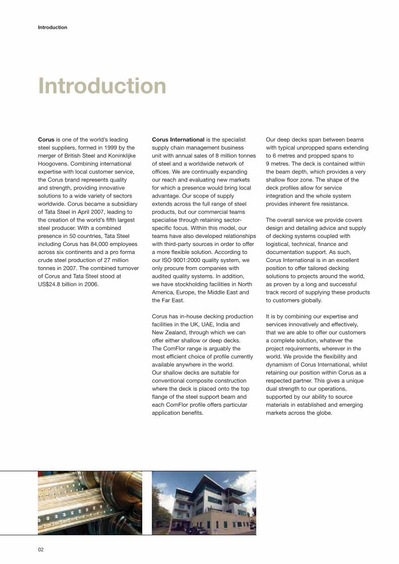
• NestableThe ultra efficient nesting capabilityof ComFlor 46 reduces the transportvolume of the product. This factcombined with the simplicity ofComFlor 46 means it is an ideal solution worldwide.
• Easy service suspensionCeilings and lightweight services caneasily be attached to the punchedhangar tabs, which can be includedwith ComFlor 46. These must bespecified at time of order.
• Low concrete usageThe trapezoidal shape profile ofComFlor 46 reduces the volume ofconcrete used, with resultant savingsin structural and foundation costs.
ComFlor 46, first introduced in 1985, is a simpletrapezoidal composite deck with a strong and reliableshear bond performance. The profile is economic andnestable, reducing transport and handling costs.
ComFlor 46Shallow composite profileTypical unpropped span 2.6m – 3.3m

05
ComFlor 46ComFlor 46 design information
ComFlor 46 composite slab – volume and weight
Weight of concrete (kN/m2)Concrete
Slab depth volume Normal weight concrete Lightweight concrete(mm) (m3/m2) Wet Dry Wet Dry
110 0.091 2.14 2.10 1.69 1.60
115 0.096 2.26 2.21 1.79 1.69
120 0.101 2.38 2.33 1.88 1.78
130 0.111 2.61 2.56 2.07 1.96
140 0.121 2.85 2.79 2.25 2.13
145 0.126 2.96 2.90 2.35 2.22
150 0.131 3.08 3.02 2.44 2.31
180 0.161 3.79 3.71 3.00 2.84
200 0.181 4.26 4.17 3.37 3.19
240 0.221 5.20 5.09 4.12 3.90
Section properties (per metre width)
Nominal Design Height to Moment of Ultimate moment capacitythickness thickness Profile weight Area of steel neutral axis inertia (kNm/m)
(mm) (mm) (kN/m2) (mm2/m) (mm) (cm4/m) Sagging Hogging
0.90 0.86 0.09 1137 20.38 41.50 4.63 4.67
1.20 1.16 0.13 1534 20.44 53.00 5.99 6.23
Volume and weight table notes
1. Deck and beam deflection (i.e. ponding)
is not allowed for in the table.
2. Deck and mesh weight is not included
in the weight of concrete figures.
3. Density of concrete is taken as:
Normal weight (wet) 2400 kg/m3
Normal weight (dry) 2350 kg/m3
Lightweight (wet) 1900 kg/m3
Lightweight (dry) 1800 kg/m3
Design notesDeck materialCorus Galvatite, hot dip zinc coated steel
EN 10326-S280GD+Z275 or equivalent.
Guaranteed minimum yield stress 280N/mm2.
Minimum zinc coating mass 275g/m2 total
both sides.
Anti-crack meshBS 5950: Part 4 currently recommends that
anticrack mesh should comprise 0.1% of slab
area. The Eurocode 4 recommendation is that
anticrack mesh should comprise 0.2% of slab
area for unpropped spans and 0.4% of slab
area for propped spans. Where forklift truck
(or other similar concentrated loading) is
expected 0.5% minimum percentage
reinforcement should be used over the
supports and 2% elsewhere to control
cracking. For further information refer to SCI
AD150. Mesh top cover must be a minimum
of 15mm, and a maximum of 30mm. Mesh
laps are to be 300mm for A142 mesh and
400mm for A193, A252 and A393 mesh.
FireFor details of the performance of composite
slabs comprising ComFlor 46 decking in
simplified design cases or for full fire
engineering, refer to the Comdek software.
Technical servicesCorus International offers a comprehensive
advisory service on design of composite
flooring, which is available to all specifiers
and users. Should queries arise which are
not covered by this literature or by the
Comdek software, please contact us.
Details of full design, load spans andprofile performance can be found by usingthe Comdek software CD. Your free copycan be found on the inside back cover ofthis publication.
Span table – Normal weight concrete
Maximum span (m)Deck thickness (mm)
Props Span Fire Slab Mesh 0.9 1.2rating depth Total applied load (kN/m2)
(mm) 3.5 5.0 10.0 3.5 5.0 10.0
1 hr 120 A193 2.4 2.4 2.4 2.8 2.8 2.6
1.5 hrs 130 A193 2.4 2.4 2.7 2.7 2.7 2.3
145 A252 2.3 2.4 2.2 2.6 2.6 2.2
2 hrs 200 A393 2.0 2.0 2.0 2.3 2.3 2.3
240 A393 1.9 1.9 1.9 2.2 2.2 2.2
1 hr 130 A193 2.7 2.7 2.7 3.2 3.2 3.1
1.5 hrs 130 A193 2.6 2.6 2.6 3.1 3.1 2.7
145 A252 2.5 2.5 2.5 2.9 2.9 2.6
2 hrs 200 A393 2.2 2.2 2.2 2.5 2.5 2.5
240 A393 2.0 2.0 2.0 2.3 2.3 2.3
No
tem
po
rary
pro
ps
Sin
gle
span
sla
b an
d de
ckD
oubl
e sp
an s
lab
and
deck Please refer to
page 20 for span
table parameters.

06
ComFlor 51
• Shear studsThe wide trough of ComFlor 51permits a flexible and efficientplacement of shear studs.
• Fire performance of the composite beamsEven for two hours fire rating, the topflange of the steel beam does notrequire fire protection, when used withComFlor 51 composite deck.
• Under floor servicesServices are easy to attach toComFlor 51, with the ribs presentinga dovetailed recessed groove in theconcrete slab at 152.5mm centres.This provides the perfect connectionfor service hangars via a wedge nutor similar type device.
• Fire performance of the slabThe dovetail presents a very smallopening and contributes little to the
transfer of heat through the slab in theevent of fire. Thus a lesser slab depthis needed for fire design purposes.
• FibreFlorComFlor 51 is fully tested with theFibreFlor system to provide all thebenefits of a mesh-free solution.Please refer to pages 36 and 37 fordetails.
ComFlor 51Shallow composite profileTypical unpropped span 2.5m – 3.6m
ComFlor 51 is a traditional dovetail re-entrant compositefloor deck. This profile provides an excellent mechanicalkey into the concrete slab, offering a strong shear bondperformance, which is augmented by cross stiffenerslocated in the profile trough. ComFlor 51 presents avirtually flat soffit and a relatively thin slab which isrequired to meet fire design requirements.

07
ComFlor 51
Design notesDeck materialCorus Galvatite, hot dip zinc coated steel
EN 10326-S350GD+Z275 or equivalent.
Guaranteed minimum yield stress 350N/mm2.
Minimum zinc coating mass 275g/m2 total
both sides.
Anti-crack meshBS 5950: Part 4 currently recommends that
anticrack mesh should comprise 0.1% of
slab area. The Eurocode 4 recommendation
is that anticrack mesh should comprise 0.2%
of slab area for unpropped spans and 0.4%
of slab area for propped spans. Where forklift
truck (or other similar concentrated loading) is
expected 0.5% minimum percentage
reinforcement should be used over the
supports and 2% elsewhere to control
cracking. For further information refer to SCI
AD150. Mesh top cover must be a minimum
of 15mm, and a maximum of 30mm. Mesh
laps are to be 300mm for A142 mesh and
400mm for A193, A252 and A393 mesh.
FireFor details of the performance of composite
slabs comprising ComFlor 51 decking in
simplified design cases or for full fire
engineering, refer to the Comdek software.
Technical servicesCorus International offers a comprehensive
advisory service on design of composite
flooring, which is available to all specifiers
and users. Should queries arise which are not
covered by this literature or by the Comdek
software, please contact us.
Details of full design, load spans andprofile performance can be found by usingthe Comdek software CD. Your free copycan be found on the inside back cover ofthis publication.
ComFlor 51 design information
ComFlor 51 composite slab – volume and weight
Weight of concrete (kN/m2)Concrete
Slab depth volume Normal weight concrete Lightweight concrete(mm) (m3/m2) Wet Dry Wet Dry
101 0.092 2.16 2.12 1.71 1.62
105 0.096 2.26 2.21 1.79 1.69
110 0.101 2.37 2.32 1.88 1.78
115 0.106 2.49 2.44 1.97 1.87
120 0.111 2.61 2.55 2.07 1.96
125 0.116 2.73 2.67 2.16 2.04
130 0.121 2.84 2.78 2.25 2.13
150 0.141 3.32 3.25 2.62 2.49
200 0.191 4.49 4.40 3.56 3.37
240 0.231 5.43 5.32 4.30 4.08
Section properties (per metre width)
Nominal Design Height to Moment of Ultimate moment capacitythickness thickness Profile weight Area of steel neutral axis inertia (kNm/m)
(mm) (mm) (kN/m2) (mm2/m) (mm) (cm4/m) Sagging Hogging
0.90 0.86 0.13 1579 16.74 55.70 5.69 6.99
1.00 0.96 0.14 1759 16.73 62.10 6.34 7.93
1.10 1.06 0.16 1938 16.73 68.50 7.00 8.88
1.20 1.16 0.17 2118 16.72 74.90 7.65 9.81
Volume and weight table notes
1. Deck and beam deflection (i.e. ponding)
is not allowed for in the table.
2. Deck and mesh weight is not included
in the weight of concrete figures.
3. Density of concrete is taken as:
Normal weight (wet) 2400 kg/m3
Normal weight (dry) 2350 kg/m3
Lightweight (wet) 1900 kg/m3
Lightweight (dry) 1800 kg/m3
Span table – Normal weight concrete
Maximum span (m)Deck thickness (mm)
Props Span Fire Slab Mesh 0.9 1.2rating depth Total applied load (kN/m2)
(mm) 3.5 5.0 10.0 3.5 5.0 10.0
1 hr 101 A142 2.8 2.8 2.5 3.2 3.2 2.8
1.5 hrs 110 A142 2.7 2.7 2.2 3.1 3.0 2.4
125 A193 2.6 2.5 2.0 2.9 2.6 2.1
2 hrs 200 A393 2.2 2.2 2.2 2.6 2.6 2.6
240 A393 2.1 2.1 2.1 2.4 2.4 2.4
1 hr 101 A142 3.2 3.2 2.6 3.7 3.7 3.0
1.5 hrs 110 A142 3.2 3.2 2.4 3.6 3.4 2.7
125 A193 3.1 3.0 2.3 3.4 3.2 2.5
2 hrs 200 A393 2.6 2.6 2.6 3.0 3.0 3.0
240 A393 2.4 2.4 2.4 2.8 2.8 2.8
No
tem
po
rary
pro
ps
Sin
gle
span
sla
b an
d de
ckD
oubl
e sp
an s
lab
and
deck Please refer to
page 20 for span
table parameters.

08
ComFlor 60
Increased span: grade 350 steelcombined with optimised finite elementanalysed profile design, givesexceptional unpropped span capabilityfor a 60 profile.
Optimum stud position: the profiledesign guarantees centrally placedshear studs.
Coated soffit: ComFlor 60 is availablewith an optional 25-micron flexiblepolyester coating to the underside, idealfor use in car parks.
Low concrete usage: the profile allows a reduced concrete volume for any slab depth delivering verycompetitive construction costs.
Lighter sheets: the cover width ofComFlor 60 is 600mm, to reduce sheetweight and improve handling.
Corus International has combined theexperience of twenty years in compositefloor profile design into the engineeringof this state-of-the-art profile. The newroll forming technology pioneered withComFlor 80 allows coated soffitcomposite flooring to be made availablenow on the 60, thus widening the rangeof choice for car parks and other similarapplications.
The profile is specifically designed toenhance shear stud interaction, with the trough stiffeners and side lapmaking it impossible to put the studs inthe wrong place. The cover width hasbeen deliberately limited to 600mm toreduce sheet weight and provide amajor health and safety benefit inmanual handling. Optimised profiledesign combined with 350 grade steelprovides exceptional spans combinedwith reduced concrete usage.
• FibreFlorComFlor 60 is fully tested with theFibreFlor system to provide all thebenefits of a mesh-free solution.Please refer to pages 36 and 37 for details.
ComFlor 60Shallow composite profileTypical unpropped span 3.0m – 4.4m
Taking the 60 profile concept to anew dimension.
‘Closed ends’
ComFlor 60 shown with
FibreFlor reinforced concrete.

09
ComFlor 60ComFlor 60 design information
ComFlor 60 composite slab – volume and weight
Volume and weight table notes
1. Deck and beam deflection (i.e. ponding)
is not allowed for in the table.
2. Deck and mesh weight is not included in
the weight of concrete figures.
3. Density of concrete is taken as:
Normal weight wet 2400 kg/m2
Normal weight dry 2350 kg/m2
Light weight wet 1900 kg/m2
Light weight dry 1800 kg/m2
Weight of concrete (kN/m2)
Concrete
Slab depth volume Normal weight concrete Lightweight concrete
(mm) (m3/m2) Wet Dry Wet Dry
120 0.089 2.09 2.04 1.65 1.57
130 0.099 2.32 2.28 1.84 1.74
140 0.109 2.56 2.51 2.03 1.92
150 0.119 2.79 2.74 2.21 2.10
160 0.129 3.03 2.97 2.40 2.27
170 0.139 3.27 3.20 2.59 2.45
180 0.149 3.50 3.43 2.77 2.63
190 0.157 3.69 3.62 2.92 2.77
200 0.167 3.93 3.85 3.11 2.95
250 0.217 5.11 5.00 4.04 3.83
Design notesDeck materialCorus Galvatite, hot dip zinc coated steel
EN10326-S350GD+Z275 or equivalent.
Guaranteed minimum yield stress 350N/mm2.
Minimum zinc coating mass 275g/m2 total
both sides.
Anti-crack meshBS 5950: Part 4 currently recommends that
anti-crack mesh should comprise 0.1% of
slab area. The Eurocode 4 recommendation
is that anti-crack mesh should comprise
0.2% of slab area for unpropped spans and
0.4% of slab area for propped spans. Where
forklift truck (or other similar concentrated
loading) is expected 0.5% minimum
percentage reinforcement should be used
over the supports and 2% elsewhere to
control cracking. For further information refer
to SCI AD150. Mesh top cover must be a
minimum of 15mm, and a maximum of
30mm. Mesh laps are to be 300mm for
A142 mesh and 400mm for A193, A252
and A393 mesh.
FireFor details of the performance of composite
slabs comprising ComFlor 60 decking in
simplified design cases or for full fire
engineering, refer to the Comdek software.
Technical servicesCorus International offers a comprehensive
advisory service on design of composite
flooring, which is available to all specifiers
and users. Should queries arise which are not
covered by this literature or by the Comdek
software, please contact us.
Details of full design, load spans andprofile performance can be found by usingthe Comdek software CD. Your free copycan be found on the inside back cover ofthis publication.
Section properties (per metre width)
Nominal Design Height to Moment of Ultimate moment capacity
thickness thickness Profile weight Area of steel neutral axis inertia (kNm/m)
(mm) (mm) (kN/m2) (mm2/m) (mm) (cm4/m) Sagging Hogging
0.90 0.86 0.103 1276 29.6 92.77 9.30 7.50
1.00 0.96 0.114 1424 30.5 106.15 11.27 9.36
1.10 1.06 0.125 1572 31.2 119.53 13.24 11.21
1.20 1.16 0.137 1721 31.7 132.91 15.21 13.07
Span table – Normal weight concrete
Maximum span (m)Deck thickness (mm)
Props Span Fire Slab Mesh 0.9 1.2rating depth Total applied load (kN/m2)
(mm) 3.5 5.0 10.0 3.5 5.0 10.0
130 A142 3.5 3.2 2.3 3.9 3.4 2.5
1 hr 130 A252 3.5 3.5 2.6 3.9 3.9 2.8
160 A252 3.2 3.2 2.9 3.6 3.6 3.1
1.5 hrs140 A193 3.4 2.9 2.1 3.7 3.1 2.3
170 A252 3.1 3.1 2.4 3.5 3.5 2.6
2 hrs150 A193 2.9 2.5 1.9 3.0 2.6 1.9
180 A252 3.1 3.0 2.1 3.5 3.0 2.2
130 A142 3.6 3.6 2.7 4.5 3.9 2.9
1 hr 130 A252 3.6 3.6 3.2 4.5 4.5 3.3
160 A252 3.3 3.3 3.3 4.2 4.2 3.8
1.5 hrs140 A193 3.5 3.5 2.6 4.1 3.6 2.7
170 A252 3.2 3.2 3.2 4.1 4.1 3.3
2 hrs150 A193 3.4 3.0 2.3 3.5 3.1 2.4
180 A252 3.1 3.1 2.8 4.1 3.9 2.9
No
tem
po
rary
pro
ps
Sin
gle
span
sla
b an
d de
ckD
oubl
e sp
an s
lab
and
deck
Please refer to
page 20 for span
table parameters.

10
ComFlor 80
ComFlor 80Shallow composite profileTypical unpropped span 3.8m – 5.1m
ComFlor 80 is the next generation of profiled steel composite decks; it is the only 80mmprofile utilising the higher grade 450 steel and available in Colorcoat®.
The large corner curvature detail provides a very efficient profile. In conjunction with thehigher grade of steel, it ensures typical unpropped spans of 4.4m simply supported and in the continuous condition, spans of 5.1m can be achieved.
The large spans achievable mean less structural steel is used and this provides savings in theoverall construction cost, which also offers more scope to architects and engineers in thedesign process.
The innovative profile designprovides real benefits• Central stud placement provides
superb composite action between thebeam and concrete due to the studbeing positioned exactly in the centreof the trough. This ensures the correctconcrete cover to the stud andtherefore, the full design capacity ofthe stud is developed. The centrallocation of the stud also reduces on-site checking by ensuring that thestud has been positioned correctly.
• Ideal for car parksComFlor 80 is available with anoptional 25-micron flexible polyestercoating to the underside, for use incar parks.
• The use of high grade 450 steel, plusthe highly efficient CF80 profiledesign, provides long span capability.
• Excellent concrete usage meansthat ComFlor 80 is very economicalcompared to other similar decks.
• Improved manual handlingThe cover width of ComFlor 80 is600mm, to reduce sheet weight andimprove handling.
• FibreFlorComFlor 80 is fully tested with theFibreFlor system to provide all thebenefits of a mesh-free solution.Please refer to pages 36 and 37 for details.

11
ComFlor 80
Design notesDeck materialCorus Galvatite, hot dip zinc coated steel
EN 10326-S450GD+Z275 or equivalent.
Guaranteed minimum yield stress up to
450N/mm2. Minimum zinc coating mass
275g/m2 total both sides.
Anti-crack meshBS 5950: Part 4 currently recommends that
anticrack mesh should comprise 0.1% of slab
area. The Eurocode 4 recommendation is that
anticrack mesh should comprise 0.2% of
slab area for unpropped spans and 0.4%
of slab area for propped spans. Where forklift
truck (or other similar concentrated loading) is
expected 0.5% minimum percentage
reinforcement should be used over the
supports and 2% elsewhere to control
cracking. For further information refer to SCI
AD150. Mesh top cover must be a minimum
of 15mm and a maximum of 30mm. Mesh
laps are to be 300mm for A142 mesh and
400mm for A193, A252 and A393 mesh.
FireFor details of the performance of composite
slabs comprising ComFlor 80 decking in
simplified design cases or for full fire
engineering, refer to the Comdek software.
Technical servicesCorus International offers a comprehensive
advisory service on design of composite
flooring, which is available to all specifiers
and users. Should queries arise which are not
covered by this literature or by the Comdek
software, please contact us.
Details of full design, load spans andprofile performance can be found by usingthe Comdek software CD. Your free copycan be found on the inside back cover ofthis publication.
ComFlor 80 composite slab – volume and weight
Weight of concrete (kN/m2 )
Concrete
Slab depth volume Normal weight concrete Lightweight concrete
(mm) (m3/m2) Wet Dry Wet Dry
130 0.086 2.03 1.99 1.61 1.53
140 0.096 2.27 2.22 1.80 1.70
150 0.106 2.51 2.45 1.98 1.88
160 0.116 2.74 2.68 2.17 2.06
170 0.126 2.98 2.91 2.36 2.23
180 0.136 3.21 3.14 2.54 2.41
190 0.146 3.45 3.38 2.73 2.59
200 0.156 3.68 3.61 2.92 2.76
250 0.206 4.86 4.76 3.85 3.64
Section properties (per metre width)
Nominal Design Height to Moment of Ultimate moment capacity
thickness thickness Profile weight Area of steel neutral axis inertia (kNm/m)
(mm) (mm) (kN/m2) (mm2/m) (mm) (cm4/m) Sagging Hogging
0.90 0.86 0.12 1387 47.6 185 15.4 12.5
1.20 1.16 0.15 1871 47.6 245 22.2 18.5
ComFlor 80 design information
90 120180
Cover width 600mm
Setting out point (s.o.p.)
95
50 3517.2
35
180 300 120
8015
15.8
Span table – Normal weight concrete
Maximum span (m)with no extra reinforcements
Deck thickness (mm)Props Span Fire Slab Mesh 0.9 1.2
rating depth Total applied load (kN/m2)(mm) 3.5 5.0 10.0 3.5 5.0 10.0
1 hr140 A252 4.2 3.6 2.5 4.5 3.8 2.7
170 A252 4.0 4.0 2.8 4.2 4.2 3.0
1.5 hrs150 A393 4.1 3.6 2.5 4.4 3.7 2.6
180 A393 3.9 3.9 2.7 4.2 4.2 2.9
2 hrs160 A393 4.0 3.1 2.3 3.8 3.1 2.3
190 A393 3.8 3.6 2.4 4.1 3.5 2.5
1 hr140 A252 4.4 4.4 3.2 5.2 4.6 3.4
170 A252 3.9 3.9 3.6 4.8 4.8 3.8
1.5 hrs150 A393 4.2 4.0 3.0 4.8 4.1 3.1
180 A393 3.8 3.8 3.5 4.7 4.7 3.6
2 hrs160 A393 4.1 3.6 2.7 4.2 3.6 2.8
190 A393 3.7 3.7 3.1 4.7 4.2 3.2
No
tem
po
rary
pro
ps
Sin
gle
span
sla
b an
d de
ckD
oubl
e sp
an s
lab
and
deck
Volume and weight table notes
1. Deck and beam deflection (i.e. ponding)
is not allowed for in the table.
2. Deck and mesh weight is not included
in the weight of concrete figures.
3. Density of concrete is taken as:
Normal weight (wet) 2400 kg/m3
Normal weight (dry) 2350 kg/m3
Lightweight (wet) 1900 kg/m3
Lightweight (dry) 1800 kg/m3
Please refer to
page 20 for span
table parameters.
12
Shallow composite floor decks Design information
Design informationComposite floor decking design is generally dictated by the construction stage condition, the load and span required forservice and the fire resistance required for the slab. The deck design is also influenced by the composite beam design.
Design parameters
• Fire rating – dictates minimum slab
depth.
• Concrete type – also dictates minimum
slab depth and influences unpropped
deck span.
• Deck span – (unpropped) usually
dictates general beam spacing.
• Slab span – (propped deck) dictates
maximum beam spacing.
Two stage design
All Composite Floors must be considered
in two stages.
• Wet concrete and construction load –
carried by deck alone.
• Cured concrete – carried by composite
slab.
General design aims
Generally designers prefer to reduce
the requirement to provide temporary
propping and so the span and slab depth
required governs the deck selection. Fire
requirements usually dictate slab depth.
For most applications, the imposed load
on the slab will not limit the design.
Quick reference and full design
The combination of this manual and
Comdek software makes both quick
reference and full design easy. Indicative
design may be carried out from the printed
tables, however the software greatly
increases the scope available to the
Design Engineer and allows the engineer
to print a full set of calculations.
British standards and Eurocodes
The Software user is offered a choice to
design to either BS5950 Parts 4 and 3 or
to Eurocode 4. The quick reference tables
are designed to BS5950 Part 4, with the
important exception of the mesh
recommendations.
Anti-crack mesh
FibreFlor can be used to replace anti
crack mesh. Where mesh is used, BS5950:
Part 4 recommends that it comprises
0.1% of slab area. The Eurocode 4
recommendation is that anti-crack mesh
should comprise 0.2% of slab area for
unpropped spans and 0.4% of slab area
for propped spans.
In slabs subject to line loads, the mesh
should comprise 0.4% of the cross-
sectional area of the concrete topping,
propped and unpropped.
These limits ensure adequate crack control
in visually exposed applications (0.5mm
maximum crack width). The mesh
reinforcement should be positioned at a
maximum of 30mm from the top surface.
Elsewhere, 0.1% reinforcement may be
used to distribute local loads on the slab
(or 0.2% to EC4).
Mesh laps are to be 300mm for A142
mesh and 400mm for A193, A252 and
A393.
Forklift trucks
Where forklift truck (or other similar
concentrated loading) is expected 0.5%
minimum percentage reinforcement should
be used over the supports and 0.2%
elsewhere to control cracking. For further
information refer to SCI AD150.
Exposed floors
Composite floors are usually covered by
finishes, flooring or a computer floor; and
because cracking is not visible, light top
reinforcement is adequate, typically 0.1%
of the gross cross sectional area. However
where the composite slab is to be left
uncovered, e.g. for power trowelled floor
finishes, cracking, particularly over the
beams, may not be adequately controlled
by the light mesh usually provided. The
cracking has no structural significance, but
the appearance of it, and the possibility of
the crack edge breakdown under traffic,
may be perceived as a problem. In this
case, refer to Concrete Society publication.
‘Cracking In Composite Concrete /
Corrugated Metal Decking Floors Slabs’
which provides valid mesh sizing and
detailing for specific crack width control.
Where forklifts are to be used also refer to
Steel Construction Institute advisory note
‘AD 150, Composite Floors – Wheel Loads
from Forklifts’. Both publications are
available from our Technical Department.
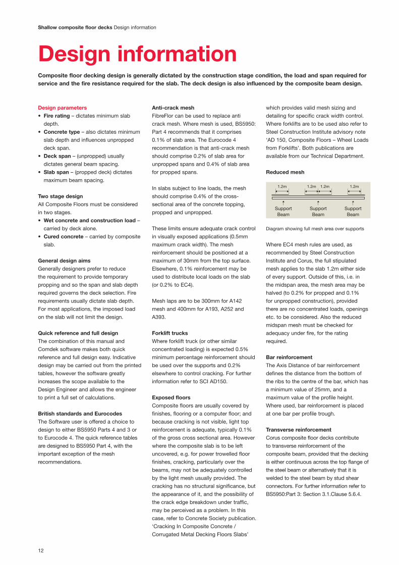
Reduced mesh
Where EC4 mesh rules are used, as
recommended by Steel Construction
Institute and Corus, the full stipulated
mesh applies to the slab 1.2m either side
of every support. Outside of this, i.e. in
the midspan area, the mesh area may be
halved (to 0.2% for propped and 0.1%
for unpropped construction), provided
there are no concentrated loads, openings
etc. to be considered. Also the reduced
midspan mesh must be checked for
adequacy under fire, for the rating
required.
Bar reinforcement
The Axis Distance of bar reinforcement
defines the distance from the bottom of
the ribs to the centre of the bar, which has
a minimum value of 25mm, and a
maximum value of the profile height.
Where used, bar reinforcement is placed
at one bar per profile trough.
Transverse reinforcement
Corus composite floor decks contribute
to transverse reinforcement of the
composite beam, provided that the decking
is either continuous across the top flange of
the steel beam or alternatively that it is
welded to the steel beam by stud shear
connectors. For further information refer to
BS5950:Part 3: Section 3.1.Clause 5.6.4.
Support Support SupportBeam Beam Beam
1.2m 1.2m 1.2m 1.2m
Diagram showing full mesh area over supports

13
Design information Shallow composite floor decks
Concrete choice
Lightweight concrete (LWC) uses
artificially produced aggregate such as
expanded pulverised fuel ash pellets.
LWC leads to considerable advantages in
improved fire performance, reduced slab
depth, longer unpropped spans and
reduced dead load. However, LWC is not
readily available in some parts of the
country. Normal weight concrete uses a
natural aggregate and is widely available.
The strength of the concrete must meet
the requirements for strength for the
composite slab and shall not be less than
25N/mm2 for LWC or 30N/mm2 for NWC.
Similarly, the maximum value of concrete
strength shall not be taken as greater than
40N/mm2 for LWC or 50N/mm2 for NWC.
The modular ratio defines the ratio of the
elastic modulus of steel to concrete, as
modified for creep in the concrete.
In design to BS5950 and BS8110, the
cube strength is used (in N/mm2). In design
to EC3, the cylinder strength is used (in
N/mm2). The concrete grade (C30/37)
defines the (cylinder/cube strength) to EC3.
Concrete density
Density kg/m3
Wet Dry Modular ratio
LWC 1900 1800 15
NWC 2400 2350 10
In the absence of more precise
information, the following assumptions
may be made: The wet density is used in
the design of the profiled steel sheets and
the dry density, in the design of the
composite slab.
Fire design
Fire insulation
The fire insulation requirements of BS
5950: Part 8, must be satisfied and are
taken into account in the tables and design
software.
Span/depth ratio
Slab span to depth ratio is limited to a
maximum of 30 for lightweight concrete
and 35 for normal weight concrete.
Shear connectors in fire situation
If shear connectors are provided, any
catenary forces transferred from the slab
to the support beams can be ignored
within the fire resistance periods quoted.
Fire design methods
There are two requirements for fire design:
• Bending resistance in fire conditions.
• Minimum slab depth for insulation
purposes.
The capacity of the composite slab in fire
may be calculated using either the Simple
Method or the Fire Engineering Method.
The simple method will be the most
economic. The fire engineering method
should be used for design to Eurocodes.
The Simple Method: The Simple Method
may be used for simply supported decks
or for decks continuous over one or more
internal supports. The capacity
assessment in fire is based on a single or
double layer of standard mesh. Any bar
reinforcement is ignored.
The Fire Engineering Method: The Fire
Engineering Method is of general
application. The capacity assessment in
fire is based on a single or double layer of
standard mesh at the top and one bar in
each concrete rib. For the shallow decks,
the program assumes the bar is positioned
just below the top of the steel deck.
Shallow composite floors generally use
the simplified fire design method which
utilises the anti-crack mesh as fire
reinforcement. Increased load span
capability under fire may be realised by
including bar reinforcement and using
the fire engineering method of design.
Deflection limits
Deflection Limits would normally be
agreed with the client. In the absence
of more appropriate information, the
following limits should be adopted:
Construction stage
Le/130 (but not greater than 30mm)
Imposed load deflection
Le/350 (but not greater than 20mm)
Total load deflection
Le/250 (but not greater than 30mm)
According to BS5950 Part 4, ponding,
resulting from the deflection of the decking
is only taken into account if the
construction stage deflection exceeds
Ds/10. Le is the effective span of the deck
and Ds is the slab overall depth (excluding
non-structural screeds).
The deflection under construction load
should not exceed the span/180 or 20mm
overall, whichever is the lesser, when the
ponding of the concrete slab is not taken
into account. Where ponding is taken into
account the deflection should not
exceed the span/130 or 30mm overall.
The quick reference tables do take
ponding into account, if deflection exceeds
Ds/10, or Le/180, and thus use span/130
or 30mm as a deflection limit.
It is recommended that the prop width
should not be less than 100mm otherwise
the deck may mark slightly at prop lines.
Vibration
The dynamic sensitivity of the composite
slab should be checked in accordance
with the Steel Construction Institute
publication P076: Design guide on the
vibration of floors. The natural frequency
is calculated using the selfweight of the
slab, ceiling and services, screed and
10% imposed loads, representing the
permanent loads and the floor. In the
absence of more appropriate information,
the natural frequency of the composite
slab should not exceed 5Hz for normal
office, industrial or domestic usage.
Conversely, for dance floor type
applications or for floors supporting
sensitive machinery, the limit may need
to be set higher.
For design to the Eurocodes, the loads
considered for the vibration check are
increased using the psi-factor for imposed
loads (typically 0.5). The natural frequency
limit may be reduced to 4Hz, because of
this higher load, used in the calculation.
Loads and load arrangement
Loading information would normally
be agreed with the clients. Reference
should also be made to BS 6399 and
to EC1.
Factored loads are considered at the
ultimate limit state and unfactored
loads at the serviceability limit state.
Unfactored loads are also considered
in fire conditions.
Partial factors are taken from BS5950,
EC3 and EC4.
Loads considered at the construction
stage consist of the slab self weight and
the basic construction load. The basic
construction load is taken as 1.5 kN/m2
or 4.5/Lp (whichever is greater), where
Lp is the span of the profiled steel sheets
between effective supports in metres.
For multi span unpropped construction,
the basic construction load of 1.5 kN/m2
is considered over the one span only.

14
Shallow composite floor decks Design information
On other spans, the construction load
considered is half this value (i.e. 0.75
kN/m2). Construction loads are considered
as imposed loads for this check.
Loads considered at the normal service
stage consist of the slab self weight,
superimposed dead loads and imposed
loads.
Openings
Openings can be accommodated readily
in composite slabs, by boxing out prior to
pouring concrete and cutting out the deck
after concrete has cured, see sitework
section on page 22. The design of
openings depends on their size:
Small
Openings up to 300mm square – do not
normally require additional reinforcement.
Medium
Openings between 300mm and 700mm
square – normally require additional
reinforcement to be placed in the slab.
This is also the case if the openings are
placed close together.
Large
Openings greater than 700mm square –
should be trimmed with additional
permanent steelwork back to the support
beams.
Opening rules
Where W = width of opening across the
span of the deck.
1. The distance between the opening and
unsupported edge must be greater than
500mm or W, whichever is the greater.
2. Openings must not be closer together
than 1.5W (of the largest opening) or
300mm, whichever is the greater. If they
are closer they must be considered as
one opening.
3. Not more than 1⁄4 width of any bay
is to be removed by openings.
4. Not more than 1⁄4 width of deck span
is to be removed by openings.
Where these rules are not satisfied, the
openings must be fully trimmed with
support steelwork.
If the opening falls within the usual
effective breadth of concrete flange of any
composite beams (typically span/8 each
side of the beam centre line), the beam
resistance should be checked assuming an
appropriately reduced effective breadth
of slab.
Slab design around openings
It may be assumed that an effective
system of ‘beam strips’ span the perimeter
of the opening. The effective breadth of the
beam strips should be taken as do/2,
where do is the width of the opening in the
direction transverse to the decking ribs.
Only the concrete above the ribs is
effective. The transverse beam strips are
assumed to be simply supported, and
span a distance of 1.5 do. The longitudinal
beam strips are designed to resist the load
from the transverse beam strips, in
addition to their own proportion of the
loading.
Reinforcement
Extra reinforcement is provided within the
‘beam strips’ to suit the applied loading.
This reinforcement often takes the form of
bars placed in the troughs of the decking.
Additional transverse or diagonal bars may
be used to improve load transfer around
the opening.
Centre lineof floor beam
Centre lineof floor beam
Deck span
Transverse reinforced concrete beam strip
Longitudinal reinforcedconcrete beam strips
Effective span of transverse beam strips = 1.5do
do/2
do/2
do
do/2 do/2
Section A-A
Section B-B
Load paths and beam strips around medium
to large openings
Mesh
Extra bars in troughs
Extra bars over deck
Extra bars in troughs
End bars in slab (over the deck)
Opening
15
Design information Shallow composite floor decks
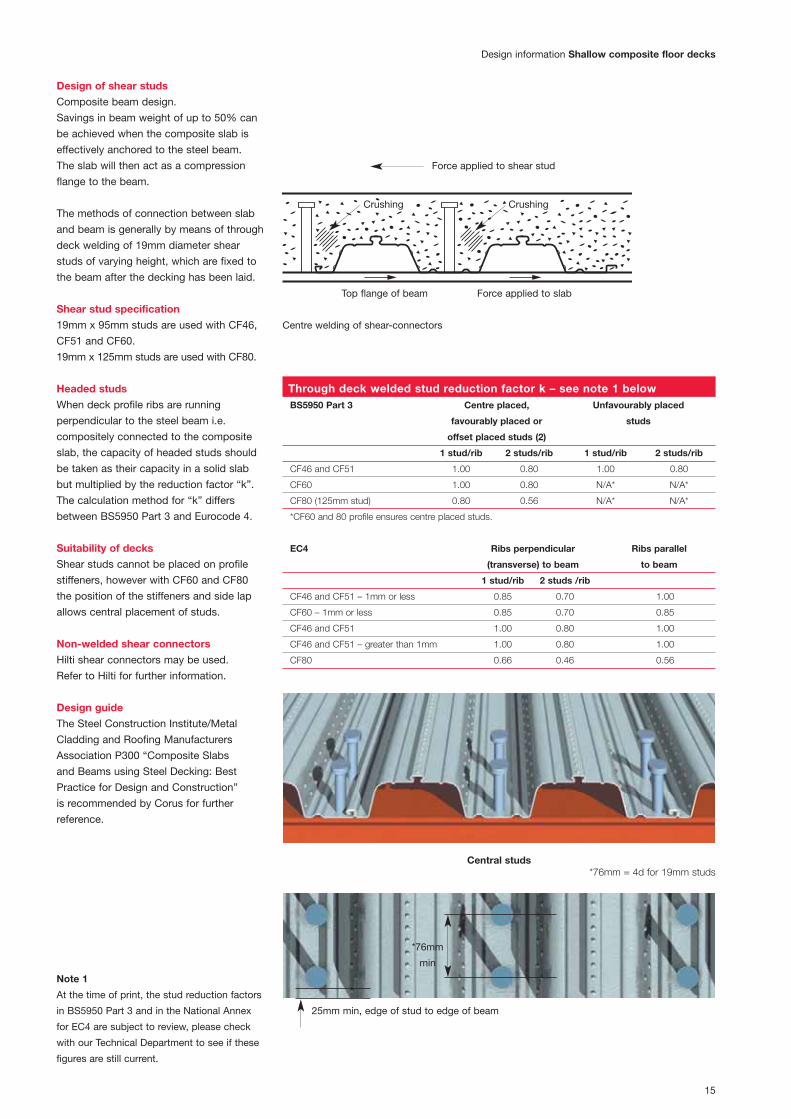
Design of shear studs
Composite beam design.
Savings in beam weight of up to 50% can
be achieved when the composite slab is
effectively anchored to the steel beam.
The slab will then act as a compression
flange to the beam.
The methods of connection between slab
and beam is generally by means of through
deck welding of 19mm diameter shear
studs of varying height, which are fixed to
the beam after the decking has been laid.
Shear stud specification
19mm x 95mm studs are used with CF46,
CF51 and CF60.
19mm x 125mm studs are used with CF80.
Headed studs
When deck profile ribs are running
perpendicular to the steel beam i.e.
compositely connected to the composite
slab, the capacity of headed studs should
be taken as their capacity in a solid slab
but multiplied by the reduction factor “k”.
The calculation method for “k” differs
between BS5950 Part 3 and Eurocode 4.
Suitability of decks
Shear studs cannot be placed on profile
stiffeners, however with CF60 and CF80
the position of the stiffeners and side lap
allows central placement of studs.
Non-welded shear connectors
Hilti shear connectors may be used.
Refer to Hilti for further information.
Design guide
The Steel Construction Institute/Metal
Cladding and Roofing Manufacturers
Association P300 “Composite Slabs
and Beams using Steel Decking: Best
Practice for Design and Construction”
is recommended by Corus for further
reference.
Through deck welded stud reduction factor k – see note 1 belowBS5950 Part 3 Centre placed, Unfavourably placed
favourably placed or studs
offset placed studs (2)
1 stud/rib 2 studs/rib 1 stud/rib 2 studs/rib
CF46 and CF51 1.00 0.80 1.00 0.80
CF60 1.00 0.80 N/A* N/A*
CF80 (125mm stud) 0.80 0.56 N/A* N/A*
*CF60 and 80 profile ensures centre placed studs.
EC4 Ribs perpendicular Ribs parallel
(transverse) to beam to beam
1 stud/rib 2 studs /rib
CF46 and CF51 – 1mm or less 0.85 0.70 1.00
CF60 – 1mm or less 0.85 0.70 0.85
CF46 and CF51 1.00 0.80 1.00
CF46 and CF51 – greater than 1mm 1.00 0.80 1.00
CF80 0.66 0.46 0.56
Central studs*76mm = 4d for 19mm studs
Centre welding of shear-connectors
Note 1
At the time of print, the stud reduction factors
in BS5950 Part 3 and in the National Annex
for EC4 are subject to review, please check
with our Technical Department to see if these
figures are still current.
25mm min, edge of stud to edge of beam
*76mm
min
Force applied to shear stud
Crushing Crushing
Top flange of beam Force applied to slab

16
Shallow composite floor decks Construction details
Construction details
Edge trim reference
Indicates cut plate245 mm wide
Indicates cut deck
Edge trimdimensions
F75
F75
Distance (mm)from centreline of tie member to Setting OutPoint (s.o.p.)of deckingfirst sheet.
X = distance (mm) from centreline ofbeam to edge of slab (parallel to deck span)
Y = distance (mm)from centreline of tiemember to edge of slab (perpendicular to deck span)
Indicates baywhich requirestemporarypropping.
94
245C P
F75
F75
X X
Beammember
centreline
Tiemember
dimensions
Y
Y
C D
6-10002107
Numberof sheets
Bundlenumber
PhaseFloorlevel
Span of decking
6-10002107
Deckinglengths
Plan view of typical floor layout Deck notation
Typical side detail
Typical side detail Unsupported edge detail
Tie member centres
25 min
25 min
Steel stud
Universal beam
Universal beam
See typical plan for
dimension ‘X’, & ‘Y’
Cantilever dimension
Steel stud
Y
Tie member centres X
For cantilevers over 150mm, additional
reinforcement is required.
CF 80
Floor decking
CF 80
Floor decking
Edge trim
Restraint
strap
at 600mm
centres
Edge trim
100mm
minimum
Edge trim
Restraint
strap
Timber
bearerReinforcement
as specified
Temporary
prop

17
Construction details Shallow composite floor decks
Butt joint
End detail Step in floor
Typical end cantilever
Beam centres
Steel stud if
applicable
Edge of flange
to side of stud
25 min
50 min
X
Beam centres
Restraint strap
Steel stud
X
CF 80
Floor decking
to extend to
edge trim
CF 80
Floor decking
Studs in pairs or
staggered where a
butt joint occurs
Deck to be butt
jointed over
centreline of beam
Restraint straps at
600mm centres
Edge trim fixed to
decking sheet
Dimension ‘X’ required
Maximum cantilever
500mm, greater
cantilevers require
temporary props and
additional reinforcement
or steelwork brackets
connected to the
Universal beam
Universal beam Universal beam
CF 80 Floor decking
to centreline of beam
For cantilevers over
150mm additional
reinforcement is
required.
RSA to be wide enough
to provide sufficient
bearing and allow fixing
of deck without fouling
top flange of beam
above
Universal beam Universal beam
Cantilever
dimension
Edge trim
25mm min.
CF 80
Floor decking
with a minimum
50mm bearing
CF 80 Floor decking
to centreline of beam
Edge trim fixed
to align with
edge of beam

18
Shallow composite floor decks Construction details
End detail alternative 2
Side cantilever with stub bracket Typical edge with plate
End detail alternative 1
Dimension required
Beam centresX Beam centresX
Stud on centreline
of beam
CF51 Floor decking
to extend to edge trim
CF51 Floor decking
to centreline of beam
For Cantilevers over
150mm additional
reinforcement is required.
Edge trim
Restraint
strap at
600mm
centres
Universal beam Universal beam
Restraint strap
Steel stud
Edge trim
Cantilever
dimension
20mm min.
Universal beam Universal beam
Edge trim
Steel stud
CF 80
Floor
decking
Steel stub as
designed by
engineer
Beam centresY
CF 80 Floor decking
Closure plate in 2mm
flat steel strip to suit
remainder of floor area
to a maximum of
245mm. Reference
CP245 (plate width)
50mm
min
Restraint
strap
Edge trim

19
Construction details Shallow composite floor decks
Typical wall end detail
Typical wall side detail Deck inside of wall detail
Beam at perimeter wall
Steel or wall to wallWall outer dimensions
CF80 Floor decking with
50mm (minimum) bearing
onto steel angle
CF80 Floor decking with
75mm (minimum) bearing
onto wall
Masonry fixing to wall at
500mm c/c
Edge trim to align with
edge of wall
100mm wall shown here
RSA, RSC or universal beam
Perimeter wall
10mm min
Overall wall dimensionBeam centres
Restraint strap
Stud on centreline of beam
X
CF80 Floor decking with
75mm (minimum) bearing
onto wall
CF51 Floor decking
to extend to edge
trim
Edge trim to align with
edge of wall
100mm wall shown here
Perimeter
wall
CE100 edge
trim leaving
room for
25mm
Korkpak joint
25
Universal beam

SiteworkFixing information for shallow decking
To steel Heavy duty powder actuated fixings – Hilti ENP2 X-ENP-19 L15 nail/Spit
SBR14 or equivalent. For temporary fixing (i.e. where weld through shear
studs are to be used) – Hilti PINDAK16*
Self-drilling screws. To steel up to 11mm thick – SFS SD14 – 5.5 x 32 /
EJOT HS 38 or equivalent. To steel up to 17mm thick SFS TDC-T-6.3
x 38 or equivalent
To masonry Pre drill hole – use self tapping fixing suitable for masonry/concrete –
or concrete SFS TB-T range/EJOT 4H32 or equivalent
To side laps Self drilling stitching screw typically SFS SL range/EJOT SF25 or
or closures etc. equivalent
Fixing spacings
ComFlor 46 ComFlor 51
and ComFlor 60 ComFlor 80
End fixing 3 per sheet
(2 per sheet when 2 per sheet
using shear studs)
Intermediate 2 per sheet
supports (1 per sheet when 1 per sheet
using shear studs)
Side laps 1 fixing at 1000mm c/c (not required for CF 51)
Side fixing onto support 1 fixing at 600mm c/c
Shallow composite floor decks Sitework
Deck fixingImmediately after laying, the deck mustbe fixed through its trough to the top ofthe supporting structure. Powderactuated pins or self-drilling screws areused. Side lap fixings are required at1000mm centres for CF46, CF60 andCF80. Where shear studs are beingused, the deck requires two fixings persheet per support at sheet ends andone fixing per sheet at intermediatesupports.
Where shear studs are not employed,the deck must be fixed as follows:
Wind loading*Where temporary fixings, such asPINDAK, are used, wind loading shouldbe checked, especially on exposedsites.
20
Parameters assumed for shallowdeck quick reference span tablesMeshSee notes on profile pages.
SpansMeasured centre to centre of supports.
DeckStandard deck material specification.
Bearing widthThe width of the support is assumed tobe 200mm.
Prop widthAssumed to be 100mm.
DeflectionConstruction stage L/130 or 30mm(ponding has been taken into account).
DeflectionComposite stage L/350.
Concrete gradeThe concrete is assumed to be grade 35with a maximum aggregate size of20mm. The wet weight of concrete istaken to be normal weight 2400kg/m3.The modular ratio is 10 for normalweight.
Construction loadNo allowance is made for heaping.
FireThe fire engineering method (FE) has been used to calculate thereinforcement needed to achieve the fire rating. The minimum slab thicknessindicated in each table for each firerating satisfies the fire insulationrequirements of BS 5950: Part 8.
Span/depth ratioThis is limited to 30 for lightweightconcrete and 35 for normal weightconcrete.

21
Bearing requirementsEnd bearing and shared bearing (minimum)
Sitework Shallow composite floor decks
Continuous bearing (minimum)
Steel section Steel section
Masonry Masonry
50mm 50mm 75mm
100mm70mm 70mm
Edge trimThis is used to retain the wet concreteto the correct level at the deckingperimeters. It is fixed to the supportsin the same manner as the deck and thetop is restrained by straps at 600mmcentres, which are fixed to the top ofthe deck profile, by steel pop rivets orself-drilling screws.
Edge trim selector
Edge Maximum cantilever (mm)
trim Galv. Steel Edge Trim Thickness (mm)
depth 0.9 1.2 1.6 2.0
130 100 125 160 195
150 0 115 150 185
200 x 100 130 160
250 x 0 100 135
300 x x 0 100
350 x x x 0
x – not recommended

22
Shear connectorsMost commonly used shear connectorsare 19mm diameter headed studs,which are welded to the support beamthrough the deck, a process carried outby specialist stud welding contractors.Site conditions must be suitable forwelding and bend tests carried out asappropriate.The spacing and position of the shearconnectors is important and must bedefined by the design engineer on thedeck set out drawings.Minimum Spacing: The minimum centre-to spacing of stud shear connectorsshould be 5d along the beam and 4dbetween adjacent studs, where d is thenominal shank diameter. Where rows ofstuds are staggered, the minimumtransverse spacing of longitudinal linesof studs should be 3d. The shear studshould not be closer than 20mm to theedge of the beam. Further guidance on shear studs for designers andinstallers may be found in The SteelConstruction Institution publications:P300 Composite Slabs and BeamsUsing Steel Decking: Best Practice forDesign and Construction, P055 Designof Composite Slabs and Beams withSteel Decking.
Mesh placementFibreFlor can be used in place of anticrack mesh, which eliminates all meshposition issues. However if reinforcingmesh is used, it is positioned towardsthe top of the slab. The top cover to thereinforcement mesh should be aminimum of 15mm and a maximum of30mm. Support stools are required tomaintain the correct mesh height. Themesh must be lapped by 300mm forA142 and A193 mesh, and by 400mmfor A252 and A393 mesh.
Casting concreteBefore the concrete is poured, thedecking must be cleared of all dirt andgrease, which could adversely influencethe performance of the hardened slab.The oil left on the decking from the rollforming process does not have to beremoved. Concrete should be pouredevenly, working in the direction of span.Care should be taken to avoid heapingof concrete in any area during thecasting sequence. Construction and dayjoints should occur over a supportbeam, preferably also at a deck joint.
Ceilings and services hanger systemsThe dovetail shaped re-entrant rib onComFlor 51 and the 15mm high raisedminidovetail re-entrant stiffener on the ComFlor 60 and ComFlor 80 profilesallow for the quick and easy suspensionof ceiling and services, using either ofthe two following suspension systems.
(a) Threaded wedge nut fixingsWedges are dovetail shaped steelblocks, which are threaded to takemetric bolts or threaded rods. Thewedge nut hanger system is installedafter the concrete of the composite slabhas been poured and is hardened.
InstallationFor installation of the system, wedgenuts are inserted into the raised re-entrants of the profile before beingrotated 90 degrees, after which thedovetail shaped wedge nuts will lockinto the dovetail re-entrants undervertical loading. Finally, the bolts orthreaded rods are finger tightened up to the roof of the re-entrants andmechanically tightened.
(b) GTD-clip hangar fixings
GTD-clip hangar fixings are cold formedthin steel hangers with circular openingsin the soffit to take metric bolts,threaded rods or further pipe clamphangers. The system is installed afterthe composite slab has been pouredand the concrete is sufficientlyhardened.
InstallationTo install the GTD-clips, the two dovetailshaped ends are compressed by handand inserted into the dovetail re-entrantof the profile, before being rotated 90degrees. One then lets go of the twoends and the clip will snap into positionand is tightly connected. Finally, bolts,threaded rods or pipe clamps areconnected into the soffit opening of theGTD-clip.
Loadbearing capacities
Thread Maximum
System size static working
load (kg)
Wedge Nut 4 100
6 100
8 100
GTD – Clip 6 90 8 90
10 90
GTD – Clip and N/A 45
Pipe Clamp
A minimum safety factor of 4 has been applied
to the safe working load capacities
ComFlor 51
ComFlor 80
Shallow composite floor decks Sitework

23
Sitework construction details
OpeningsOpenings greater than 300mm must be designed by the engineer, with extrareinforcement placed around theopening. Openings up to 700mm canbe accommodated readily in compositeslabs, by boxing out prior to pouringconcrete and cutting out the deck afterconcrete has cured. Larger openingsrequire support trimming steel, whichmust be installed prior to the decking.The decking is cut away immediatelyand the opening edges are then treatedlike any other perimeter with edge trim.
Note: do not cut the opening in thesteel deck prior to concreting, orbefore the concrete has cured.
Temporary supportsThe safe design and installation oftemporary props is the responsibility ofthe main contractor or designated sub-contractor. Where temporary supportsare required by the design, these mustprovide continuous support to theprofiled sheeting. Spreader beams(timbers) are used, supported bytemporary props at one metre centres.[a] The timbers and props must be ofadequate strength and construction[b] The temporary supports are placedat midspan or at other suitable centresif more supports per span are required.Please contact our Technical Department[c] The spreader beams or timbers areto provide a minimum bearing width of100mm. The spreaders must not deflectmore than 10mm and should be placednarrow edge up, see diagram.[d] The propping structure is not to beremoved until the concrete has reachedat least 70% of its characteristicstrength. The horizontal bearer timbersmust be at least 100mm wide andshould be propped at no more than 1mcentres. Sometimes the specificationmay call for 150mm wide bearers, asdetermined by the structural engineeror concreting contractor.
Props should be stable without relyingon friction with the deck for laterialstability. The end props in a row shouldbe self supporting, and braced to theinternal props.
Percussive drillingPercussive drilling into compositeconcrete slabs is not recommended,however small scale rotary hammer drillsare considered to be satisfactory.
Temporary props
Timber bearer guide (shallow decks)
All to be min. 100mm wide
Slab depth (mm) Bearer depth (mm)
up to 120 150
130 – 160 200
170 – 200 250
Timber shutter
Temporary support using an
‘Acrow’ type prop
Dense polystyrene block
Sitework construction details Shallow composite floor decks

ComFlor 210Deep composite profileTypical unpropped span4.5m – 6.0m
24
ComFlor 210
The original SlimFlor long span steel deck, ComFlor 210has the capability to span up to 6 metres in unproppedconstruction. Suitable for use in Corus Slimdek®
construction, which offers minimal structural depth,fast construction and many other benefits.• With cross and longitudinal stiffeners,
CF210 is structurally efficient andoffers excellent composite action withthe concrete.
• Simple single bar reinforcement ineach trough, combined with anti-crack mesh near the top of theconcrete slab gives the compositeslab superb structural strength andfire properties.
• The nestable profile shape reducestransport and handling costs.
• Up to 2 hours fire rating withunprotected soffit.

25
ComFlor 210ComFlor 210 design information
Design notes
Deck material
Corus Galvatite, hot dip zinc coated steel
EN 10326-S350GD+Z275 or equivalent.
Guaranteed minimum yield stress 350N/mm2.
Minimum zinc coating mass 275g/m2 total
both sides.
Anti-crack mesh
BS 5950: Part 4 currently recommends that
anticrack mesh should comprise 0.1% of slab
area. The Eurocode 4 recommendation is that
anticrack mesh should comprise 0.2% of slab
area for unpropped spans and 0.4% of slab
area for propped spans. Where forklift truck
(or other similar concentrated loading) is
expected 0.5% minimum percentage
reinforcement should be used over the
supports and 2% elsewhere to control
cracking.
For further information refer to SCI AD150.
Mesh top cover must be a minimum of
15mm, and a maximum of 30mm. Mesh laps
are to be 300mm for A142 mesh and 400mm
for A193, A252 and A393 mesh.
Technical services
Corus International offers a comprehensive
advisory service on design of composite
flooring, which is available to all specifiers
and users. Should queries arise which are not
covered by this literature or by the Comdek
software, please contact us.
Fire
For details of the performance of composite
slabs comprising ComFlor 210 decking in
simplified design cases or for full fire
engineering, refer to the Comdek software.
Bar reinforcement
End anchorage for bar reinforcement. All
cases require properly anchored L-bars at the
supports, except for those indicated in yellow.
Cases indicated in yellow may have straight
bars, with an anchorage length of 70mm from
the edge of the support. One bar is placed in
each profile trough, the cover to deck soffit is
assumed at 70mm.
Details of full design, load spans and
profile performance can be found by using
the Comdek software CD. Your free copy
can be found on the inside back cover of
this publication.
ComFlor 210 composite slab – volume and weight
Weight of concrete (kN/m2)
Concrete
Slab depth volume Normal weight concrete Lightweight concrete
(mm) (m3/m2) Wet Dry Wet Dry
270 0.100 2.36 2.31 1.87 1.77
280 0.110 2.60 2.54 2.05 1.95
290 0.120 2.83 2.77 2.24 2.12
300 0.130 3.07 3.00 2.43 2.30
305 0.135 3.18 3.12 2.52 2.39
310 0.140 3.30 3.23 2.61 2.48
330 0.160 3.77 3.69 2.99 2.83
350 0.180 4.24 4.16 3.36 3.18
375 0.205 4.83 4.73 3.83 3.62
400 0.230 5.42 5.31 4.29 4.07
Section properties (per metre width)
Nominal Design Height to Moment of Ultimate moment capacity
thickness thickness Profile weight Area of steel neutral axis inertia (kNm/m)
(mm) (mm) (kN/m2) (mm2/m) (mm) (cm4/m) Sagging Hogging
1.25 1.21 0.16 2009 95.00 816.00 23.20 23.20
Volume and weight table notes
1. Deck and beam deflection (i.e. ponding)
is not allowed for in the table.
2. Deck and mesh weight is not included
in the weight of concrete figures.
3. Density of concrete is taken as:
Normal weight (wet) 2400 kg/m3
Normal weight (dry) 2350 kg/m3
Lightweight (wet) 1900 kg/m3
Lightweight (dry) 1800 kg/m3
Span table – Normal weight concrete
Maximum span (m)Total applied load (kN/m2)
Props Span Fire Slab Mesh 3.5kN/m2 5kN/m2 10kN/m2
rating depth Bar size (mm)(mm) 12 16 20 25 12 16 20 25 12 16 20 25
280 A142 4.8 5.4 5.4 5.4 4.3 5.4 5.4 5.4 3.4 4.5 5.4 5.4
1 hr 300 A193 4.8 5.2 5.2 5.2 4.4 5.2 5.2 5.2 3.5 4.6 5.2 5.2
350 A393 4.7 4.7 4.7 4.7 4.5 4.7 4.7 4.7 3.7 4.7 4.7 4.7
290 A193 3.7 4.9 5.3 5.3 3.4 4.4 5.3 5.3 2.7 3.5 4.3 5.3
1.5 hrs 300 A193 3.7 4.9 5.2 5.2 3.4 4.5 5.2 5.2 2.7 3.6 4.4 5.2
350 A393 3.8 4.7 4.7 4.7 3.5 4.6 4.7 4.7 2.8 3.8 4.6 4.7
305 A193 2.0 2.7 3.3 4.1 1.8 2.4 3.0 3.7 1.5 1.9 2.4 3.0
2 hrs 350 A393 2.1 2.7 3.4 4.2 1.9 2.5 3.1 3.8 1.5 2.0 2.5 3.1
400 A393 2.1 2.7 3.4 4.2 1.9 2.6 3.2 3.9 1.6 2.1 2.6 3.3
No
tem
po
rary
pro
ps
Sin
gle
span
sla
b
Please refer to page 29 for span tableparameters.

26
Design informationDeep Composite Floor Decks will be considered where longer span (4m plus) floor slabs are required. When combined with Corus Slimdek® system, deep decks are designed to achieve a very shallow overall structural floor.
Deep composite floor decksOur Deep Composite Floor Decks willbe used in one of these applications:1 Corus Slimdek® system.2 Long span composite concrete/steel
floor deck in composite steelconstruction.
3 Long span composite concrete/steelfloor deck in masonry construction.
The design considerations relatingto the decking are similar for all theseapplications.
Corus Slimdek® systemThis system comprises AsymmetricSlimflor® Beams (ASB) and deep CF210decking.
The principle of Slimdek® is that thesteel deck (and thus the compositeconcrete slab) bears on the lower flangeof the beam, thus containing the beamwithin the floor slab. Three differenttypes of Slimflor® beam are produced:
Deep composite floor decks Design information
Asymmetric Slimflor® Beam (ASB), which is a hot rolled section with a narrower top flange than
bottom flange.
Slimflor® Fabricated Beam (SFB), which is a Universal Column section with a wide flange plate
welded to its underside.
Rectangular Hollow Slimflor® Beam (RHSFB), which is a rectangular hollow section with a flange
plate welded to its lower face (generally used for edge beams).

27
Slimdek® design procedureThere are two distinct stages for whichthe elements of the Slimdek® systemmust be designed. The first is theconstruction stage, during which thebeams and decking support the loadsas non-composite sections. During thesecond stage the decking and concreteact together to form composite slabs, asdo (generally) the ASBs and slab. SFBsand RHSFBs will act compositely ifshear studs have been provided.
The key design points are:• Consideration of the required spans
will allow the depth of the beams tobe determined.
• Consideration of the required fireresistance will allow the depth of slabto be determined, as a function of thecover required for the beams and thedecking.
Having established these schemedesign parameters, detailed design ofthe beams and slab can be undertaken.The following slab depths should beconsidered as typical:280 ASB sections – 290-320mm deep slab300 ASB sections – 315-340mm deep slab.
These depths will provide adequatecover to the ASB for it to actcompositely with the slab. For SFBs agreater range of slab depths may beconsidered for a given depth of beam;the slab depth requirement will dependon whether shear studs must beaccommodated to make the SFB actcompositely.
Slimdek® beam designThe design of the beams in the Slimdek®
system is presented in The CorusSlimdek® Manual and Design Softwarewhich is available from CorusConstruction Centre +44 (0)1724405060. Further detailed designinformation is available in The SteelConstruction Institute publications: P300Composite Slabs and Beams UsingSteel Decking: Best Practice for Designand Construction, P055 Design ofComposite Slabs and Beams with SteelDecking. Please see references sectionon page 38 for further information.
Decking designIn addition to considering the self-weight of the slab, the design of thedeep decking should take into accounttemporary construction loads. Theseconstruction loads differ slightly fromthose that should be considered forshallow decking, because of theconsiderably greater spans that can beachieved with deep decking.
Construction stage loadingThe 1.5 kN/m2 construction loadrequired by BS 5950-4 should only beapplied over the middle 3m of the span,as shown below.
A reduced load of 0.75 kN/m2 (asspecified in EC4) may be appliedoutside this region, as it would be overlyconservative to apply the full load of1.5kN/m2 over the entire span. Theeffect of concrete ponding should betaken into account (by increasing theself weight of the slab) if the deflectionunder self-weight alone exceeds thelesser of span/180 or 20mm.
If temporary props are used to supportthe decking during construction, aconstruction load of 1.5 kN/m2 shouldbe considered as acting over thecomplete span (between permanentsupports). Although a lower value mightbe justifiable over parts of the span, aconstant load should be considered fordesign simplicity.
Temporary propping (when required)The spacing of temporary props isgoverned by the ability of the decking to resist combined bending and shear inthe hogging (negative) moment regionsover the lines of props.
It is recommended that the spacingbetween the props should be relativelyclose, so that local loads do not causedamage to the decking (2.5m to 3.5mspacing depending on the slab weight).
A 100mm wide timber bearer should be used to distribute the load at thesepoints.
End bearingThe end bearing of the sheets should be specified as 50mm. The flangewidths are such that this bearing can beachieved, whilst still allowing the sheetsto be dropped vertically into position(i.e. without having to ‘thread’ thembetween the top and bottom flanges).
Design information Deep composite floor decks
Reduced construction load0.75 kN/m2 x 1.6
Self weight x 1.4
3m
Clear span + 0.075m
Construction load1.5 kN/m2 x 1.6

28
Slab designThe design of composite slabs usingdeep decking differs from that forshallow decking in the following ways:
Placing bar reinforcement in the troughsof the decking increases the ultimateload resistance of the slab. The benefitof these bars is considered in both the‘normal’ and fire conditions.
The slab depth may need to be chosennot only to satisfy the structural,durability and fire resistancerequirements of the slab itself, but alsoto provide appropriate cover over ASBor Slimflor beams.
The reinforcing bars in the troughs of thedecking provide additional tensile areato that provided by the decking, andthus enhance the bending resistance ofthe composite slab.
Bar diameters range from 8mm to 32 mm, depending on the span and fire resistance requirements.
Straight bars may be used to achieve 60 minutes fire resistance (provided that shear stresses are low). In othercases, L bars should be used to provide sufficient end anchorage in fire conditions.
CrackingIt is normal for some cracking to occurin the slab over the beams. Thesecracks run parallel with the beams andare not detrimental to the structuralbehaviour of the slab. They may becontrolled by mesh reinforcementprovided across the tops of the beams.Guidance on the detailing ofreinforcement to control cracking maybe found in the Corus Slimdek® manual.
Additional reinforcement may berequired to fulfil the following roles:• Transverse reinforcement adjacent to
shear connectors.• U-bars at composite edge beams.• Additional crack control
reinforcements• Strengthening around openings.• Strengthening at positions of
concentrated loads.
Fire resistanceOne of the principal considerationsgoverning the choice of slab depth isthe required fire resistance period.Minimum depths are given above as afunction of the concrete type and fireresistance required and are based oninsulation requirements.The Fire Engineering Method: Thecapacity assessment in fire is basedon a single or double layer of standard
mesh at the top and one bar in eachconcrete rib. For CF210 decking, the baris placed at an axis distance, dependenton the fire resistance period. The axisdistance must not be less than 70mm.To maximise fire resistance capacity theaxis distance needs to be 70, 90 and120mm (from the soffit of the deck) for60, 90 and 120 minutes fire resistance,respectively. However where fireresistance is not the limiting factor itmay be more effective for the axisdistance to be at the minimum.
Reduced meshWhere EC4 mesh rules are used, asrecommended by The SteelConstruction Institute and Corus, the full stipulated mesh applies to the slab1.2m either side of every support.Outside of this, i.e. in the midspan area,the mesh area may be halved (to 0.2%for propped and 0.1% for unproppedconstruction), provided there are noconcentrated loads, openings etc. to beconsidered. Also the reduced midspanmesh must be checked for adequacyunder fire, for the rating required.
VibrationThe dynamic sensitivity of thecomposite slab should be checked inaccordance with the SCI publicationP076: Design guide on the vibration offloors. The natural frequency iscalculated using the self-weight of theslab, ceiling and services, screed and10% imposed loads, representing thepermanent loads and the floor selfweight.
In the absence of more appropriateinformation, the natural frequency of thecomposite slab should not exceed 5Hzfor normal office, industrial or domesticusage. For designs using CF210decking, this limit may be reduced to4Hz if the design has been carried out
Deep composite floor decks Design information
Concrete thickness above deck
Fire resistance NWC LWC
60min 70mm 60mm
90min 80mm 70mm
120min 95mm 80mm
Support Support SupportBeam Beam Beam
1.2m 1.2m 1.2m 1.2m
Diagram showing full mesh area over supportsVerticalreaction
Slip betweendeck and concrete
Longitudinalshear bond
Bar reinforcement Stressdistribution
Tensionin deckingand bar reinforcement
Concrete incompression
Mid spanSupport
100mm100mm
50 ø
12 ø25
ø
ø
29
on the assumption of simple supports at the ends. Conversely, for dance floortype applications or for floors supportingsensitive machinery, the limit may needto be set higher.
In the Slimdek system, considerationshould be given to the system frequencyof the floor as a whole if the naturalfrequency of the slab and/or thesupporting beam is less than 5Hz.
For design to the Eurocodes, the loadsconsidered for the vibration check areincreased using the psi-factor forimposed loads (typically 0.5). Thenatural frequency limit may be reducedto 4Hz, because of this higher load used in the calculation.
Partial continuityPartial continuity for deep decking: Tests have shown that the CF210composite slabs supported on a steelbeam and provided with adequatelydetailed continuity mesh reinforcementover the steel beam support exhibits adegree of continuity at the support. The beneficial effect of partial continuityat the supports may be taken intoaccount by specifying CONTINUOUS inthe Span Type field. When this option isspecified, the following assumptions aremade by the design software;• a 20% reduction in the deflections of
the composite slab at the normaldesign stage.
• a 30% reduction in the deflectionswhen assessing the natural frequencyof the slab. This is justified by thelower stress levels during vibration.
• stresses in the composite slab in fireconditions are derived from a modelwhich assumes full continuity at oneend and a simple support at the other(i.e a propped cantilever condition).
In this case, the amount of meshreinforcement is increased to a minimumof 0.4% of the cross-sectional area ofthe concrete topping in order to developsufficient continuity in the slab.
Note that in all cases, partial continuityis ignored in assessing the capacity ofthe composite slab at the normal designstage.
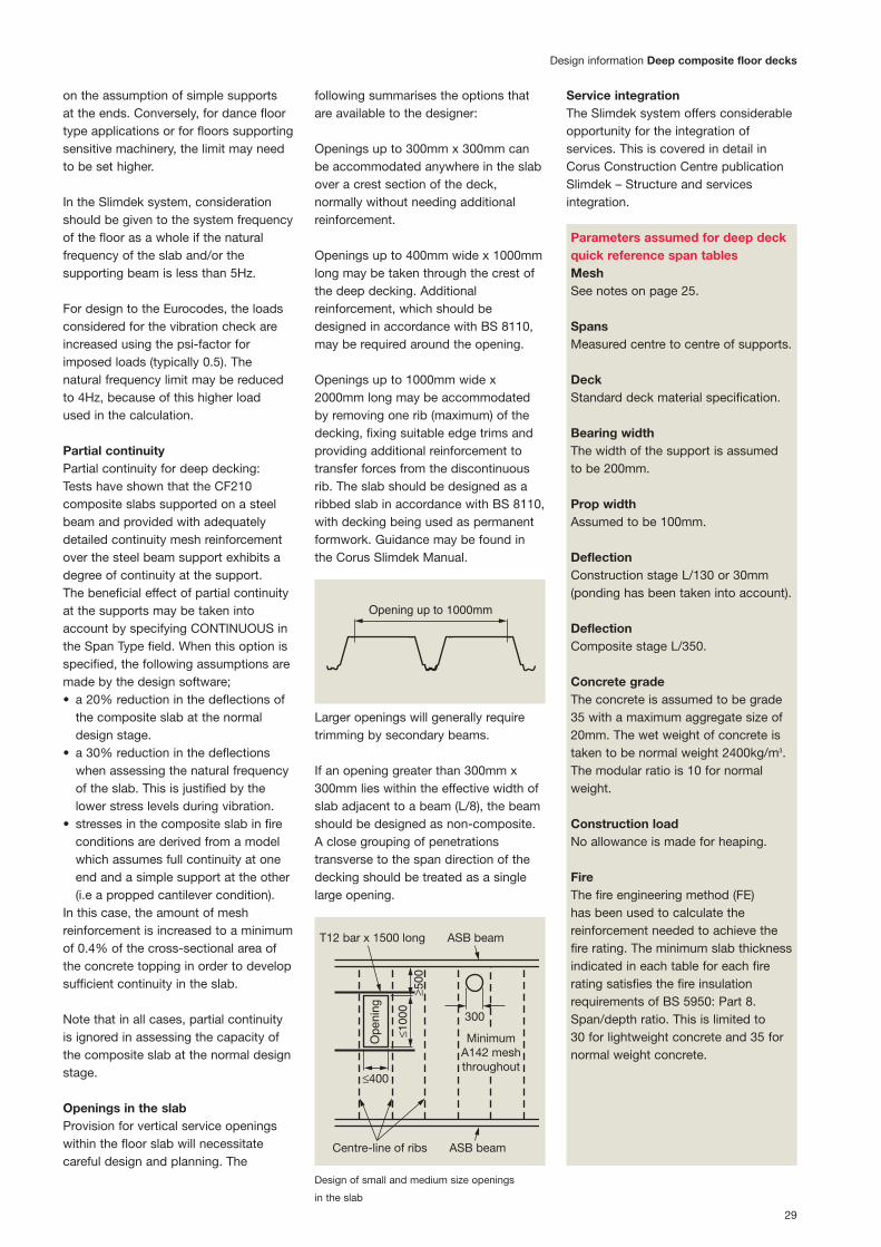
Openings in the slabProvision for vertical service openingswithin the floor slab will necessitatecareful design and planning. The
following summarises the options thatare available to the designer:
Openings up to 300mm x 300mm canbe accommodated anywhere in the slabover a crest section of the deck,normally without needing additionalreinforcement.
Openings up to 400mm wide x 1000mmlong may be taken through the crest ofthe deep decking. Additionalreinforcement, which should bedesigned in accordance with BS 8110,may be required around the opening.
Openings up to 1000mm wide x2000mm long may be accommodatedby removing one rib (maximum) of thedecking, fixing suitable edge trims andproviding additional reinforcement totransfer forces from the discontinuousrib. The slab should be designed as aribbed slab in accordance with BS 8110,with decking being used as permanentformwork. Guidance may be found inthe Corus Slimdek Manual.
Larger openings will generally requiretrimming by secondary beams.
If an opening greater than 300mm x300mm lies within the effective width ofslab adjacent to a beam (L/8), the beamshould be designed as non-composite.A close grouping of penetrationstransverse to the span direction of thedecking should be treated as a singlelarge opening.
Service integrationThe Slimdek system offers considerableopportunity for the integration ofservices. This is covered in detail inCorus Construction Centre publicationSlimdek – Structure and servicesintegration.
Design information Deep composite floor decks
Opening up to 1000mm
≤400
≤100
0≥5
00
Ope
ning
MinimumA142 meshthroughout
T12 bar x 1500 long ASB beam
300
Centre-line of ribs ASB beam
Design of small and medium size openings
in the slab
Parameters assumed for deep deckquick reference span tablesMeshSee notes on page 25.
SpansMeasured centre to centre of supports.
DeckStandard deck material specification.
Bearing widthThe width of the support is assumedto be 200mm.
Prop widthAssumed to be 100mm.
DeflectionConstruction stage L/130 or 30mm(ponding has been taken into account).
DeflectionComposite stage L/350.
Concrete gradeThe concrete is assumed to be grade 35 with a maximum aggregate size of20mm. The wet weight of concrete istaken to be normal weight 2400kg/m3.The modular ratio is 10 for normalweight.
Construction loadNo allowance is made for heaping.
FireThe fire engineering method (FE) has been used to calculate thereinforcement needed to achieve the fire rating. The minimum slab thicknessindicated in each table for each firerating satisfies the fire insulationrequirements of BS 5950: Part 8.Span/depth ratio. This is limited to 30 for lightweight concrete and 35 fornormal weight concrete.

30
Deep composite floor decks Construction details
Cut deck – Option 1
Cut deck – Option 3
Unsupported edge Unsupported edge with closure flashing
Cut deck – Option 2
Edge trimEdge trim
Reinforcement
as specified
Reinforcement
as specified
100mm
Closure
flashing
Restraint strap
Temporary propTemporary props
required for spans
greater than 500mm
Restraint strap at
600mm centres
Beam centres
CF210 Deck
cut along top
section only
Closure flashing
Asymmetric
SlimFlor beam
100 min 370-405
Beam centres
CF210 Deck
cut along top
section only
Closure flashing Closure flashingAsymmetric SlimFlor beam Asymmetric SlimFlor beam
100 min 165-185
Beam centres
CF210 Deck
cut along top
section only
100 min 240-270
Construction details

31
Construction details Deep composite floor decks
Steel trims
Notations used on deck layout drawing
End fixing onto RHS Side fixing onto RHS
Number of sheets
Floor level
Phase
Bundle number
Prop decking in this area
Side of decking run that requiresZ ’ flashing
Distance from centreline of tiemember to sop of first decking sheet
Decking lengths
Span of decking6-55554105
Z2
94
Beam centres
CF210 Floor decking
CF210 Floor decking
with 75mm minimum
bearing onto steelwork
Beam centres
60030
100
RHS with steel plate
(300x200 RHS shown here
Dec
k s.
o.p
.
75
100
CF210 End diaphragm
90
50
190
(150 max)
20
50 min (steel)
75 min(blockwork)
Slabdepth

Health and safetyComFlor 210 should only be installed by contractors experienced in fixing long span steel decking.
It is the responsibility of the contractorto provide safe working procedures forthe installation of deep decking on anyparticular project and to provide a riskassessment to the main contractor.
Reference should be made to the BCSACode of Practice for Metal Decking andStud Welding, with special reference tothe addendum for long span decking.
The following general guidelines shouldalso be followed to maximise health andsafety on site
1. Diaphragms should where reasonablypracticable be fitted from a safeworking platform or from below froma MEWP or a platform accesssystem.
2. Deck cutting should be carried out asthe last operation in each bay. Thus itcan be carried out on a safe workingplatform of previously laid deck.
End diaphragmsSteel end diaphragms, as manufacturedby Corus, are essential for both deepdeck systems to ensure the structuralintegrity of the deck. The enddiaphragms, are fixed first and aresupplied in lengths of 1800mm, to coverthree of our deep deck profiles. They arefixed using at least two shot-fired pinsfor each length; in the Slimdek systemthe end diaphragms align with the edgeof the lower flange of the beam.
Single diaphragms are available withpre-punched service holes in two types.Type 1 has one 160mm diameter hole;Type 2 has one elongated 160mmdiameter hole to make opening 320mmwide x 160mm high.
Unpunched single diaphragms are alsoavailable. Where the deep deck landsonto a support at a rake, the singlediaphragms are used doubled up, andadjusted on site to take up the extralength required due to the fact that theend of the deck is at a raked angle tothe support rather than at right angles.
The concrete that the diaphragmsentrap around the Asymmetric SlimflorBeam, give the beam its fire rating,therefore the diaphragms must beplaced strictly according tospecification.
Deck fixingThe decking sheets are manuallylowered individually onto the beams. In the Slimdek system, the end bearingof the sheets should be 50mm; theflange widths are such that this can beachieved, whilst still being able to dropthe sheets vertically into position (i.e.without having to thread them betweenthe top and bottom flanges).
Once the sheets for the whole bay are in place, they are secured to the beamflanges using heavy duty shot-firedfixings. CF 210 requires one main fixingper trough.
Where CF210 deck is being used withAsymmetric SlimFlor Beams, the topflange of the profile must be notchedback by 50mm, so that the concrete canbe observed passing between the enddiaphragm and the beam to allowconcrete to flow into the beam.
The crown of the deck sheet is fixed tothe top of the diaphragms using one selfdrilling screw for CF210.
When fixing to other types of supportssuch as reinforced concrete, or loadbearing walls, 1 suitable fixing must beused in each CF210 trough as for thesteel supports.
Side lapsCF210 side laps are to be stitched at350mm centres with 5.5mm diameterself drilling screw, the location is markedby an indentation in the overlap tail.Every side lap fastener must fix andlocate a trough shear connector clip intoposition. The clip is partly responsiblefor the composite action of the deckingand must not be omitted unless theCF210 is being used as formwork only.
32
Sitework
Fixing information for deep decking
To steel Heavy duty powder actuated fixings – Hilti ENP2 X-ENP-19 L15 nail/Spit
SBR14 or equivalent. For temporary fixing (i.e. where weld through shear
studs are to be used) – Hilti PINDAK16
Self-drilling screws. To steel up to 11mm thick – SFS SD14 – 5.5 x 32 /
EJOT HS 38 or equivalent. To steel up to 17mm thick SFS TDC-T-6.3
x 38 or equivalent
To masonry Pre drill hole – use self tapping fixing suitable for masonry/concrete –
or concrete SFS TB-T range/EJOT 4H32 or equivalent
To side laps Self drilling stitching screw typically SFS SL range/EJOT SF25 or
or closures etc. equivalent
End diaphragm for ComFlor 210
ComFlor 210 shear clip
Deep composite floor decks Sitework

33
Fixing spacings
ComFlor 210
End fixing 1 per trough
Side laps 1 fixing with shear clip at
350mm c/c
Side fixing 1 fixing at 600mm c/c
onto support
Sitework Deep composite floor decks
View from above
Fixing of ComFlor 210
1 heavy duty shot fired pin per trough for
fixing into steelwork
Side laps stitched at 350mm centres
including trough shear-bond clip
1 heavy duty shot fired pin per trough for
fixing into steelwork
End diaphragm
End diaphragm
Deck top
Beam top

34
Edge detailsThe steelwork must be stable andadequately restrained with support forthe deck around columns and openings.Corus deep decking can be easily cut,and fitted, to accommodate columnsand other awkward shapes. Where thereis no supporting steelwork, bracketsfixed to the column will have to be usedfor local support to the deck.
Light steel edge trim is used to form theedges of the slab and to infill where the600mm profile of the deck does notalign with the parallel supports. Suppliedin 3m lengths as standard, and offeredin thickness of 1.2mm to 2.0mm, theedge trims are fixed to the perimetersteel beams, using the same shot firedfasteners that secure the deck. Theupper leg is strapped to the crown ofthe profile, to prevent buckling duringthe concrete pouring operation.
CantileversOur deep decks can be Cantileveredin its length up to 500mm duringconstruction. When Cantilevers arerequired perpendicular to the span ofthe profile, stub beams or some similartype of support has to be supplied.In both cases, the Cantilever mustbe assessed, for the final stage,in accordance with BS8110 Part 1,to determine whether additionalreinforcement is required.
ReinforcementThe decking forms a part of the slabreinforcement, with the remainder beingsupplied by a bar in each trough of thedecking and a mesh placed near to thetop of the slab. Reinforcement shouldbe fixed in accordance with therequirements of the Structural Designer.Normally, circular plastic spacers areused to position the bars 70mm fromthe base of the trough. This distancecan increase to 90 or 120mm(respectively) when 90 or 120 minutesfire resistance are required. There maybe additional mesh or bar requirementsto fix adjacent to the supports or edgebeams, or above beams for crackcontrol purposes.
Any shear studs that are required (tomake SFBs or RHSFBs composite) maybe welded to these sections duringfabrication, because they do notinterfere with the decking. If they are tobe welded on site, the precautions andprocedures outlined on page 32 shouldbe considered.
Deep composite floor decks Sitework
Edge trims selector
Edge Maximum Cantilever (mm)
trim Galv. Steel Edge Trim Thickness (mm)
depth
(mm) 1.6 2.0
270 100 135
300 0 100
350 x 0
400 x 0
x – not recommended
Fit restraint straps at 600mm c/c to prevent
any bowing of edge trim.
35
Information of particular interest toComposite Flooring Contractors is givenbelow.
Receiving deckingComposite Floor Decking is packed intobundles of up to 24 sheets, and thesheets are secured with metal banding.Each bundle may be up to 950mm wide(the overall width of a single sheet) by750mm deep, and may weigh up to 2.5tonnes, depending on sheet length(average weight is about 1.5 tonnes).Loads are normally delivered byarticulated lorries approximately 16mlong with a maximum gross weight of upto 40 tonnes, and a turning circle ofapproximately 19m. The MainContractor should ensure that there issuitable access and appropriatestanding and off-loading areas.
Each bundle has an identification tag.The information on each tag should bechecked by operatives from the deckingcontractor (or, if they are not on site, theMain Contractor) immediately uponarrival. In particular, the stated sheetthickness should be checked againstthe requirement specified on thecontract drawings, and a visualinspection should be made to ensurethat there is no damage.
Lifting bundlesThe bundles should be lifted from thelorry. Bundles should never be off-loaded by tipping, dragging, dropping orother improvised means.
Care is needed when lifting the deckingbundles; protected chain slings arerecommended. Unprotected chain slingscan damage the bundle during lifting;when synthetic slings are used there is arisk of the severing them on the edgesof the decking sheets.
If timber packers are used, they shouldbe secured to the bundle before liftingso that when the slings are releasedthey do not fall to the ground (withpotentially disastrous results). Bundlesmust never be lifted using the metalbanding.
Positioning the deckingThe support steelwork should beprepared to receive the decking beforelifting the bundles onto it. The topsurface of the underlying beams shouldbe reasonably clean. When thru-deckwelding of shear studs is specified, thetops of the flanges should be free ofpaint or galvanising.
The identification tags should be used toensure that bundles are positioned onthe frame at the correct floor level, andin the nominated bay shown on thedeck layout drawing. The bundlesshould be positioned such that theinterlocking side laps are on the sameside. This will enable the decking to belaid progressively without the need toturn the sheets. The bundles should alsobe positioned in the correct spanorientation, and not at 90° to it. Careshould be taken to ensure that thebundles are not upside down,particularly with trapezoidal profiles. The embossments should be orientedso that they project upwards.
Placement of deckingThe breaking open of bundles andinstallation of decking should only beginif all the sheets can be positioned andsecured. This will require sufficient timeand suitable weather. The deckinglayout drawing should also be checkedto ensure that any temporary supportsthat need to be in position prior to decklaying are in place. Access forinstallation will normally be achievedusing ladders connected to the steelframe. Once they have started laying outthe sheets, the erectors will create theirown working platform by securely fixingthe decking as they progress.
The laying of sheets should begin at thelocations indicated on the deckinglayout drawings. These would normallybe at the corner of the building at eachlevel; to reduce the number of ‘leadingedges’, i.e. unprotected edges, wherethe decking is being laid. When thebundles have been properly positioned,as noted above, there should be noneed to turn the sheets manually, andthere should be no doubt which way upthe sheet should be fixed.
Individual sheets should be slid intoplace and, where possible, fixed to thesteelwork before moving onto the nextsheet. This will minimise the risk of anaccident occurring as a result ofmovement of a sheet when it is beingused as a platform. (However, forsetting-out purposes, it may benecessary to lay out an entire bay usinga minimum number of temporary’ fixingsbefore fully securing the sheets later).
Sheets should be positioned to providea minimum bearing of 50mm on thesteel support beams. The ends ofadjacent sheets should be buttedtogether. A gap of up to 5mm isgenerally considered not to allowexcessive seepage, but, if necessary,the ends of the sheets may be tapedtogether. When end gaps are greaterthan 5mm, it is normally sufficient toseal them with an expanding foam filler.The longitudinal edges should beoverlapped, to minimise concreteseepage.
Cutting sheetsWhere necessary, sheets may be cutusing a grinder or a nibbler. However,field cutting should be kept to aminimum and should only be necessarywhere a column or other obstructioninterrupts the decking. Gaps adjacent tothe webs of columns should be filled inwith off- cuts or thin strips of steel.Decking sheets shown as continuous onthe decking layout drawing should neverbe cut into more than one length. Also,sheets should never be severed at thelocation of a temporary support, and thedecking should never be fastened to atemporary support.
As the work progresses, unwantedscraps and off-cuts should be disposedof in a skip placed alongside theappropriate level of working. The skipshould be positioned carefully over asupport beam to avoid overloading thedecking If a skip is not available, scrapsshould be gathered for collection by theMain Contractor as soon as is possible.Partially used bundles should besecured, to avoid individual sheetsmoving in strong winds.
Transport and handlingTransport and handling
36
FibreFlor
36
FibreFlor mesh free composite floor systemFibreFlor is a partnership betweenCorus and Propex Concrete Systems,the world’s largest supplier of fibrereinforcement for concrete.
Benefits of FibreFlorCost savings• Labour cost savings• Up to 20% programme savings• No mesh to purchase, transport or
store• Reduction in crane hire costs• Potential concrete volume savings.
Easier to install• No hoisting/lifting or manual handling
of mesh• No steel fixing/tying requirements• No spacer requirements• 3-Dimensional reinforcement delivered
ready mixed in concrete• Easier concrete application (No trip
hazards or snagging from mesh)• Fibre reinforcement always in the
correct position.
Technical superiority• Independent testing proves that the
FibreFlor system provides equivalentor superior performance to traditionalwelded wire mesh solutions
• Quality assured concretereinforcement system
• FibreFlor is proven to reduce plasticshrinkage and settlement cracking
• Unlike macro-synthetic fibres, themicro-synthetic fibres in FibreFlorare also proven to mitigate theexplosive spalling tendency ofconcrete during fires
• The inclusion of steel fibres inFibreFlor provides load bearingcapabilities, increased toughnessand long term crack control.
FibreFlor uses a combination of highperformance steel fibres andpolypropylene micro-synthetic fibres toprovide a three dimensional fibrereinforced concrete composite slab.
Traditionally composite metal deckconstruction utilises mesh fabricreinforcement. This involves the delivery,lifting and installation of welded wiremesh on to the floor prior to the pouringof concrete. The time and costs involvedmake mesh relatively unpopular withcontractors and the mesh itself is ahindrance to other site operations.Maintaining the correct mesh height,position, concrete cover and laps canbe difficult during mesh placement andconcrete pouring.
FibreFlor reinforcement is providedwithin the concrete, delivered and readyto pump at site. Significantly this canreduce installation times by up to 20%.
FibreFlor is a certified floor deck systemthat eliminates the need for steel wiremesh and is currently available asFibreFlor CF51, FibreFlor 60 andFibreFlor CF80.

37
FibreFlor
FibreFlorIn recognition of the many practicaldifficulties associated with the use oftraditional welded wire fabric in upperfloor construction and in response to theever increasing demands for improvedspeed of construction, improved qualityand cost effectiveness, Corus andPropex Concrete Systems have joinedforces to develop FibreFlor.
FibreFlor is a combination of Novoconhigh performance steel fibres andFibermesh micro-synthetic fibresproviding a unique three dimensionalconcrete reinforcement solution forcomposite metal decks and designed toreplace traditional welded wire mesh.
By combining the attributes of bothtypes of fibre, FibreFlor providesperformance benefits over the entire lifespan of the concrete – from simplifyingplacement, to minimising cracks in theplastic state, to controlling cracks in thehardened state, to providing years ofexceptional durability.
In the development of FibreFlor, it wasidentified that many properties wererequired to provide both an optimumtechnical solution for the necessary firerating, but also practically in providing aconcrete solution that is easily handled,pumped and finished. The world leadingbrand of Fibermesh micro-syntheticfibres are proven to inhibit both plasticshrinkage and settlement cracking.Additional benefits include increased
impact and abrasion resistance togetherwith reduced permeability of theconcrete. Fibermesh micro-syntheticfibres are also internationally proven toprovide resistance to explosive spalling,in the event of fire.
Novocon high performance steel fibresare proven to provide both a high levelof ductility to the concrete and longterm crack control. This allows the loadcarrying capability to replace traditionalmesh reinforcement. Testing approvedby the Steel Construction Instituteconfirmed that FibreFlor also providedlongitudinal shear resistance in excessof that provided by A393 steel wirefabric.
FibreFlor reinforced composite metaldeck systems have been extensivelytested in accordance with BS EN 1365-2:2000 standards at NAMAS certifiedfire test facilities, under the guidance ofthe Steel Construction Institute (SCI).
Results, analysed and approved bythe SCI, show that FibreFlor reinforcedcomposite metal deck systems provideequivalent or superior performance totraditional wire mesh solutions with fireratings of up to two hours.
Independent testing of ComFlor
composite floor deck at the Namas certified
fire test facility.

38
References Health and Safety
British standardsThe design guidance given in thisbrochure and on the attached softwarecomplies, where relevant, with thefollowing Standards.
Composite floor deck1. BS 5950: Part 4 1994. Structural use
of steelwork in building: Code ofpractice for design of compositeslabs with profiled steel sheeting.
Composite steel beams2. BS 5950: Part 3: 1990. Design in
composite construction: Section 3.1:1990. Code of practice for design ofsimple and continuous compositebeams.
Profiled steel deck3. BS 5950: Part 6 1995. Structural use
of steelwork in building: Code ofpractice for design of light gaugeprofiled steel sheeting.
Fire resistance4. BS 5950: Part 8 1990. Structural use
of steelwork in building: Code ofpractice for fire resistant design.
Concrete5. BS 8110: Part 1: 1997 Structural use
of concrete: Code of practice fordesign and construction.
6. BS 8110: Part 2: 1985 Structural useof concrete: Code of practice forspecial circumstances.
Reinforcement7. BS 4483: 1998 Specification for
steel fabric for the reinforcement ofconcrete.
8. BS4449:1997 Specification forcarbon steel bars for thereinforcement of concrete.
Eurocode 49. ENV 1993 – 1-3: Design of steel
structures. Supplementary rules forcold formed thin gauge membersans sheeting.
10. ENV 1994 – 1-1: Design ofComposite steel and concretestructures. General rules for building.
11. ENV 1994 – 1-2: Design ofcomposite steel and concretestructures. Structural fire design.
12. SCI – P – 076 : Design guide on thevibration of floors. SCI in associationwith CIRIA (1989).
Health and SafetyHandling hazardsZinc coated steel decking should behandled with care; it may be deliveredwith soluble protective layer of oil, whichcan cause contamination to laceratedskin. Decking will have sharp edges andcorners. Adequate gloves and protectiveclothing should be worn when handlingdecking.
Eye hazardsEye protectors conforming to thespecification in BS 2092:1987 shouldalways be worn, when breaking thestrapping around bundles because thesudden release of tension creates a riskto eyes. Particles of metal also createeye hazards when cutting steel, and eyeprotection should be worn, during thisactivity.
Noise hazardsNoise may be hazardous whilst handlingor cutting decking, shot firing, etc,adequate ear defenders should be worn.
Respiratory hazardsFumes containing oxides of iron andzinc are produced during welding orflame cutting and if inhaled these maycause metal fume fever; this is a short-lasting condition with symptoms similarto those of influenza. In conditions ofexposure to such hazards, the use ofrespiratory equipment is recommended.
Explosives and fumesWhen using shot fired fixings explosivesand fumes may create a hazard.
Occupational exposure limitsLimits for iron and zinc oxides are5g/m≥ (8 hours TWA) and 10mg/m≤ (10minutes TWA). (OE recommendation).
Summary of protective measuresWear adequate gloves and protectiveclothing and safety goggles.Ensure adequate ventilation and usepersonal protective equipment.Follow instructions for safe handling,use, disposal and control of cartridgesissued by equipment supplier.Ensure adequate ventilation and/or usepersonal respiratory protectiveequipment. Use appropriate eardefenders or earplugs.
Installation of deep decksSee advice on page 32 for special health and safety considerationsregarding installation of deep decks.
General safety pointsFollow the good practice outlined hereand in SCI publications.• Always fix deck securely before using
as a working platform.• Steel end diaphragms, as
manufactured by Corus Panels andProfiles, are essential for both deepdeck systems to ensure the structuralintegrity of the deck.
• Rigorously employ all personal safetymeasures such as hard hats,protective clothing.
• Rigorously employ all site safetymeasures such as safety lines, edgeprotection, properly tied ladders.
• Don’t leave any unfixed deckingsheets.
• Don’t heap concrete or drop from anyheight.
• Don’t put heavy loads on unprotecteddeck.
• Don’t place props on uncuredconcrete.
• Don’t cut holes/voids in the deck priorto concreting.
ReferencesHealth and Safety

39
Comdek software References
Download instructionsThe comprehensive Comdek softwarefor the design of composite floor slabs,is freely available, to all professionalswho register, athttp://www.comflor.com
Another link to Comdek is also availablefromhttp://www.corusinternational.com
Use of the design programAll the variables start with a defaultvalue, however check or input newvariables on both Datasheet 1 andDatasheet 2. When satisfied click‘Analyse’ to run the calculations.
Job details may be entered for a formalprintout.
It is not necessary to put in shearconnectors (shear studs) for thecomposite slab design (shearconnectors are used primarily for thebenefit of the beam not the slab).However if shear connectors are to beused, then the design software allowsend anchorage to be accounted forwhich in some cases will improve theload capacity of the composite slab.
Before accepting a particular design assatisfactory, it is highly advisable to printout the calculations and check that allthe input parameters are correct.
Design criteria and methodsThe design program has been producedby the Steel Construction Institute onbehalf of Corus International.
Help function on discThe Help function on the designprogram contains all the detailedinformation that is used to produce the calculations.
ComdekSoftware

www.comflor.com
Care has been taken to ensure that this
information is accurate, but Corus Group plc,
and its subsidiaries, does not accept
responsibility or liability for errors or
information which is found to be misleading.
Copyright 2007
Corus
Corus International Projects897 Silbury BoulevardCentral Milton KeynesMK9 3XJUnited KingdomT: +44 (0)1908 508 250F: +44 (0)1908 508 258www.corusinternational.com
Corus International Australasia7 Bruce Roderick DriveEast TamakiPO Box 58880, GreenmountAuckland, New ZealandT: +64 (0)9 271 1780F: +64 (0)9 271 1970www.corusinternational.com
Corus Middle East FZEPO Box 18294Jebel AliDubaiUnited Arab EmiratesT: +971 (0)4 887 3232F: +971 (0)4 887 3966www.corusinternational.com
Corus International Asia24 Raffles Place#29-05 Clifford CentreSingapore 048621SingaporeT: +65 6 297 6678F: +65 6 297 6682www.corusinternational.com
Corus International India (Pvt) Ltd503/504 Raheja Chambers213 Backbay ReclamationMumbai 400-021IndiaT: +91 22 2282 3126F: +91 22 2287 5148www.corusinternational.com
Corus International Americas475 North Martingale RoadSuite 400 SchaumburgIllinois 60173USAT: +1 847 619 0400F: +1 847 619 1952 www.corusinternational.com