Embed Size (px)
Citation preview
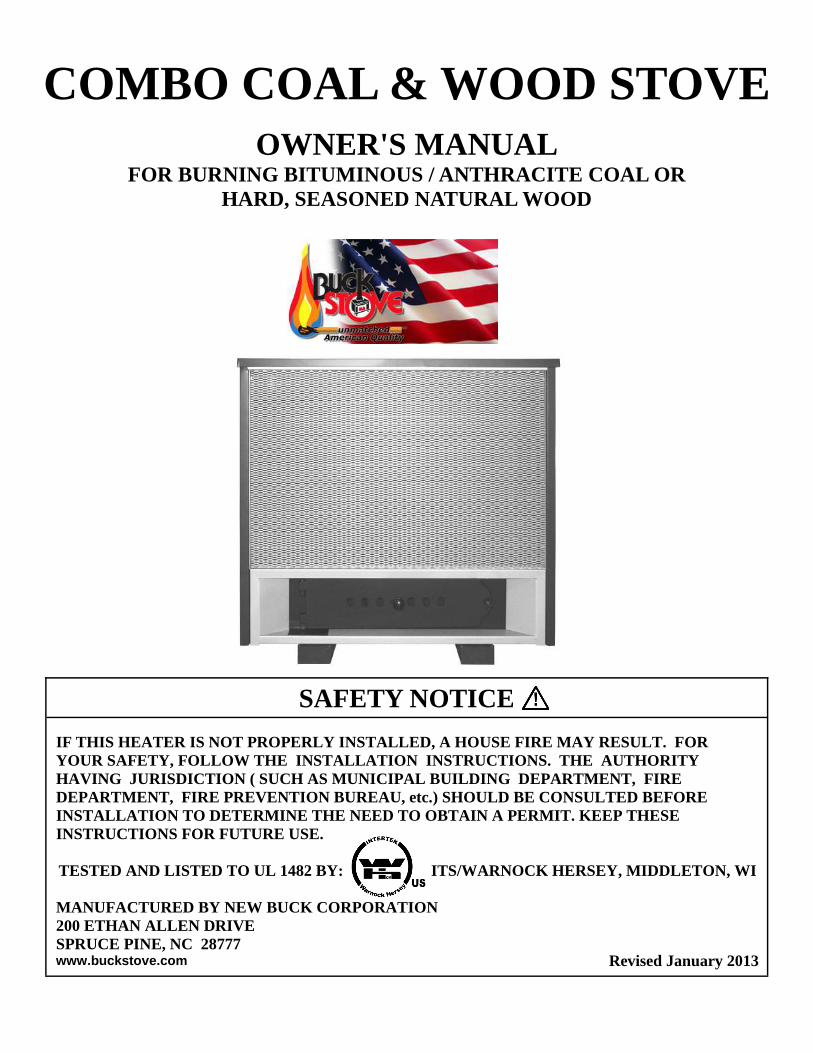
COMBO COAL & WOOD STOVE
OWNER'S MANUAL FOR BURNING BITUMINOUS / ANTHRACITE COAL OR
HARD, SEASONED NATURAL WOOD
Revised January 2013
SAFETY NOTICE
IF THIS HEATER IS NOT PROPERLY INSTALLED, A HOUSE FIRE MAY RESULT. FOR YOUR SAFETY, FOLLOW THE INSTALLATION INSTRUCTIONS. THE AUTHORITY HAVING JURISDICTION ( SUCH AS MUNICIPAL BUILDING DEPARTMENT, FIRE DEPARTMENT, FIRE PREVENTION BUREAU, etc.) SHOULD BE CONSULTED BEFORE INSTALLATION TO DETERMINE THE NEED TO OBTAIN A PERMIT. KEEP THESE INSTRUCTIONS FOR FUTURE USE. TESTED AND LISTED TO UL 1482 BY: ITS/WARNOCK HERSEY, MIDDLETON, WI MANUFACTURED BY NEW BUCK CORPORATION 200 ETHAN ALLEN DRIVE SPRUCE PINE, NC 28777 www.buckstove.com


TABLE OF CONTENTS
Important Installation Instructions ...................................................................................................... 2
Introduction.......................................................................................................................................... 3
Installation ........................................................................................................................................... 4
Chimney Connection - Chimney ........................................................................................................ 5
Thimble - Connection to a Metal Prefabricated Chimney ................................................................. 7
Methods of Installations ...................................................................................................................... 8
Preparing Room Heater Location ........................................................................................................ 9
A) Rear Exit Into Flue using (6" Single Wall Pipe minimum 24 ga. blued or black pipe) or (6" DVL Close Clearance Pipe) .................................................................... 10
B) Rear Exit to Vertical then to Horizontal into Flue using (6" Single Wall Pipe minimum 24 ga. blued or black pipe with Elbows) or (6" DVL Close Clearance Pipe with Elbows) ...................................................................................................... 13
C) Rear exit into Masonry Fireplace using (6" Single Wall pipe, minimum 24 ga. blued or black pipe) .................................................................................................................... 16
D) Rear Exit to Vertical Ceiling Exit using (6" Single Wall minimum 24 ga. blued or black pipe with Elbow) or (6" DVL Close Clearance Pipe with Elbow) and any (Listed 2100° UL 103 HT Chimney) .................................................................................. 18
E) Rear Exit Through Wall, Exterior Chimney Outside Residence using (6" Single Wall pipe minimum 24 ga. blued or Black pipe) or (6" DVL Close Clearance Pipe) and any (Listed 2100° UL. HT chimney and Listed 2100° UL HT T-Box assembly) ............................................................................................................ 20
Reduced Wall Clearances .................................................................................................................. 22
Cautions ............................................................................................................................................. 23
Operation for Burning Wood Fuel ..................................................................................................... 24
Operation for Burning Coal Fuel ....................................................................................................... 26
Shaker, Feed Door, and Ash Dump Door Handle ............................................................................. 28
Maintaining a Fire ............................................................................................................................. 29
Ash Removal and Disposal ............................................................................................................... 29
Blower and Installation ( Optional ) .................................................................................................. 30 .
Warranty ............................................................................................................................................. 31

Page 2
INSTALLATION, OPERATION, AND MAINTENANCE INSTRUCTIONS COMBO COAL & WOOD STOVE
READ THIS FIRST
IMPORTANT INSTRUCTIONS
The Combo Coal & Wood Stove has been tested by ITS, Warnock Hersey to ANSI/UL Standards 1482.
Install and operate your units according to instructions provided in this manual. Local building codes may apply; therefore, contact your local building inspector or fire marshal for necessary installation requirements and permits which may go beyond these instructions.
THIS UNIT IS NOT APPROVED FOR MOBILE HOME USE.
DO NOT INSTALL IN SLEEPING ROOMS.
NOTE: When burning any unit or appliance that combust fuel for heat, such as coal, oil, wood or natural and (L.P.) liquid petroleum gas, we highly recommend use of smoke and carbon monoxide detectors in your home.
Examine the masonry fireplace and chimney prior to installation of fireplace accessory to determine that construction meets minimum fireplace construction requirements illustrated in the instructions. Ensure that the chimney is free from cracks, loose mortar, creosote deposits and other blockage, or other signs of deterioration.
FUELING AND ASH REMOVAL DOORS MUST REMAIN CLOSED WHEN IN
OPERATION.
WARNING
THESE UNITS GENERATE A LOT OF HEAT, SO TREAT THEM WITH CARE. HOT WHILE IN OPERATION! KEEP CHILDREN, CLOTHING AND FURNITURE AWAY. CONTACT MAY CAUSE SKIN BURNS. READ ALL INSTRUCTIONS BEFORE INSTALLING AND USING THE APPLIANCE. FAILURE TO FOLLOW INSTRUCTIONS MAY RESULT IN PROPERTY DAMAGE, BODILY INJURY, OR EVEN DEATH. SAVE THESE INSTRUCTIONS FOR FUTURE REFERENCES.
CAUTION
Do not connect this unit to a chimney flue serving another appliance. Do not use a flue in-tended for a gas appliance. Do not connect to any distribution duct or system.
Page 3
You should not burn trash or garbage, artificial or paper logs, gift wrapping, treated or painted wood.
INTRODUCTION The Combo Coal & Wood Stove is a highly efficient heating unit. Proper installation will ensure years of heating satisfaction. Read the manual carefully. For more information, contact a local dealer. Safety is a vital factor in installing your stove. Without correct installation and operation, a house fire may result. Check local codes. DO NOT USE CHEMICALS OR FLUIDS TO START THE FIRE. DO NOT BURN GARBAGE OR FLAMMABLE FLUIDS.
Under specific test conditions this heater has been shown to deliver heat at rates ranging from approximately 45,000 to 50,000 BTU/HR. This unit may also be used with optional room air blower. To order optional motor assembly you must specify stove model name and give the following part number: *Model Combo Coal & Wood Stove Motor Assembly — MA CCOAL714
For operation and use of this electrical assembly, see instructions provided with motor assembly kit.
CAUTION
Your chimney or flue must be correctly sized. A chimney or flue that is too small or large in diameter, or too short, can cause your stove to spill smoke when door is opened.
Read the complete manual before installing and operating. Failure to follow instructions may result in property damage, bodily injury or death.
NOTE: When burning any unit or appliance that combust fuel for heat, such as coal, oil, wood or natural and (L.P.) liquid petroleum gas. We highly recommend use of smoke and carbon monoxide detectors in your home.

Page 4
INSTALLATION MINIMUM CLEARANCES TO FLOOR AND COMBUSTIBLES See minimum floor protector measurements. For minimum clearances to combustibles, see pages listed below.
A-1. Rear Exit into Flue 6” Single Wall Pipe( Page 11)
A-2. Rear Exit into Flue 6” DVL ( Page 12)
B-1. Rear Exit to Vertical to Horizontal into Flue 6” Single Wall Pipe( Page 14)
B-2. Rear Exit to Vertical to Horizontal into Flue 6” DVL Pipe( Page 15)
C. Rear Exit to Fire Place 6” Single Wall Pipe( Page 17)
D. Rear Exit to Vertical Ceiling 6” Single Wall Pipe or 6” DVL Pipe ( Page 19)
E. Rear Exit Thru Wall, Exterior Chimney outside Residence (6” Single Wall Pipe or 6” DVL Pipe to (Listed 2100ºUL 103 HT TYPE Chimney T-Box Asembly and Listed 2100ºUL 103 HT TYPE Chimney) ( Page 21)
Floor Protection: When installing freestanding heater, a floor protector must be used. Must have minimum R-value of 1.8.
How to use alternate materials and how to calculate equivalent thickness An easy means of determining if a proposed alternate floor protector meets requirements listed in the appliance manual is to follow this procedure: 1. Convert specification to R-value:
R-value is given—no conversion is needed. K-factor is given with a required thickness (T) in inches: C-factor is given: R=1/C
2. Determine R-value of the proposed alternate floor protector. Use formula in step (1) to convert values not expressed as “R” For multiple layers, add R-values of each layer to determine overall R-value.
3. If overall R-value of the system is greater than R-value of the specified floor protector, the alternate is acceptable.
Example: The specified floor protector should be 3/4” thick material with a K-factor of 0.84. The proposed alternate is 4” brick with a C-factor of 1.25 over 1/8” mineral board with a K-factor of 0.29.
Step (a): Use formula above to convert specification to R-value. R= 1/K x T = 1/0.84 x .75 = 0.893
Step (b): Calculate R of proposed system. 4” brick of C=1.25, therefore Rbrick = 1/C = 1/1.25 =0.80 1/8”
mineral board of K = 0.29, therefore Rmin.bd. =1/029 x0.125 = 0.431
Step (c): Compare proposed system R of 1.231 to specified R of 0.893. Since proposed system R is greater than required , the system is acceptable.
Definitions:
Thermal conductance = C = Btu
= W
(hr)(ft²)(°F) (m²)(°K)
Thermal conductance = K = (Btu)(inch)
= W
= (Btu)
(hr)(ft²)(°F) (m)(°K) (hr)(ft)(°F)
Thermal conductance = R = (ft²)(hr)(°F)
= (m²)(°K)
Btu W

Page 5
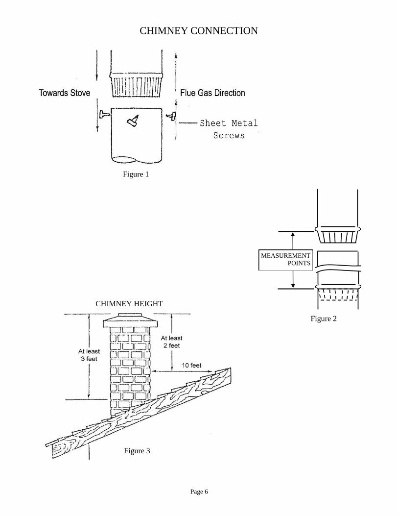
CHIMNEY CONNECTOR The chimney size should not be less than or more than three times greater than the cross-sectional area of the flue collar.
1. Chimney connector must be 6” diameter, 24 gauge minimum steel. 2. Do not use aluminum or galvanized steel. 3. Do not use chimney connecter pipe as a chimney. 4. Connect stove to either a Factory-Build or Masonry Factory-Build chimney that complies with
UL 103 HT Standard. 5. Chimney connector sections must be attached to stove and to each other with crimped end
towards stove. (See Page 9 Figure 40. This allows creosote to run into the stove and not onto the outside of the pipe.
6. Secure all joints with three sheet metal screws and use furnace cement on all joints. Without proper security, in the event of a creosote fire, connector may vibrate apart.
7. For maximum operation, chimney connector should be as short as possible. 8. Horizontal lengths of chimney connector should have an upward slope of 1/4” per foot. 9. Maintain an 18” clearance between chimney connector and ceiling.
CHIMNEY This room heater must be connected to:
(1) A chimney complying with the requirements for Type HT Chimneys, Factory– Built Residential Type and Building Heating Appliance; UL 103.
(2) A code-approved masonry chimney with a flue liner.
Your stove will operate satisfactorily with any listed factory-built chimney or any masonry flue or chimney meeting NFPA-211 Codes. A round chimney is preferable to a square or rectangular chimney. The ideal chimney will have a cross-sectional area of the stove flue collar opening. Maximum flue collar draft = .025 w.c. MASONRY CHIMNEY If stove is connected to a masonry chimney, it should be examined for cracks, loose mortar, blockage or other signs of deterioration. Do not install stove until chimney is determined safe for use. An oversized flue contributes to accumulation of creosote. Check flue size to determine it is not too large for stove. Flue should be no larger than 8” square or 9” in diameter. Chimney must be the required height above roof for proper draft operation. Chimney height requirement: At least 3’ above the roof At least 2’ above highest point on roof At least 10’ away from the highest point (See Page 6 Figure 3)
Page 6
Figure 1
Figure 3
CHIMNEY HEIGHT
CHIMNEY CONNECTION
Figure 2
MEASUREMENT POINTS
Page 7
THIMBLE Prefabricated “Listed 2100° UL 103 HT Type Chimney” metal thimbles can be purchased for use (See Page 19 and 21). Installation instructions from manufacturer must be strictly followed to ensure safety of the system. Clearances to combustible materials must be maintained. Confirm local building codes for restrictions when connecting stove to masonry thimble through a combustible wall.
CONNECTION TO A METAL PREFABRICATED CHIMNEY When a metal prefabricated chimney is used, follow pipe manufacturer's installation instructions exactly. Do not mix different pipe. All parts must be from the same pipe manufacturer.
1. Ceiling support package 2. Wall pass through 3. "T" section package 4. Firestops (when needed) 5. Insulation shield 6. Roof flashing 7. Chimney cap
Two methods of chimney installation: 1. Back exit through wall, exterior chimney outside residence. Use listed 2100° UL 103
HT Type Chimney and T-Box assembly system. (See figure 4, Page 8). 2. Back exit to vertical ceiling exit. Use listed 2100° UL 103 HT Type Chimney.
(See figure 5, Page 8). Components illustrated may not look like the system you chose, but this demonstrates basic components needed for a proper and safe installation. See figure 3 (Page 6) for chimney height. Refer to page 5, "Masonry Chimney" for dimensions. NOTE: Follow manufacturer's installation instructions and maintain specified
clearance requirements.
These parts must be listed to 2100 degree UL 103 HT.
DO NOT CONNECT THIS UNIT TO A CHIMNEY FLUE SERVING ANOTHER APPLIANCE.
Page 8
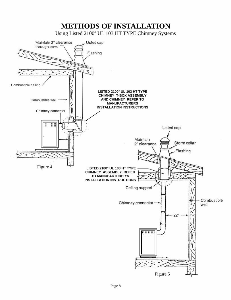
METHODS OF INSTALLATION Using Listed 2100º UL 103 HT TYPE Chimney Systems
Combustible ceiling
Combustible wall
Chimney connector
Figure 4
22”
Figure 5
LISTED 2100° UL 103 HT TYPE CHIMNEY ASSEMBLY. REFER
TO MANUFACTURER’S INSTALLATION INSTRUCTIONS
LISTED 2100° UL 103 HT TYPE CHIMNEY T-BOX ASSEMBLY
AND CHIMNEY REFER TO MANUFACTURERS
INSTALLATION INSTRUCTIONS

Page 9
PREPARING ROOM HEATER LOCATION 1. Select an installation location that will give best airflow from front of heater to the remainder of the
home. 2. Place protective floor pad in position. 3. Place unit on pad making sure minimum clearance specifications are met. 4. If connecting to an existing masonry flue, first ensure that the flue conforms to NFPA-211 Code and/or consult your local code for proper procedures.
This model is designed for connection to any Listed 2100° UL 103 HT. TYPE chimney, also any Listed UL DVL Close Clearance Pipe. Follow pipe manufacturer’s instructions carefully.
CHIMNEY
This room heater must be converted to (1) a chimney complying with the requirements for Type HT chimneys in the Standard for Chimneys, Factory-Built, Residential, Type and Building Heating Appliance, UL 103, or (2) a code approved masonry chimney with a flue liner.
CAUTION: Certain installation types require use of certain chimney types. Please fol-low these instructions exactly.

Page 10
A. Rear Exit Into Flue using (6" Single Wall Pipe minimum 24 ga. blued or black pipe) or (6" DVL Close Clearance Pipe)
HOW TO LOCATE CHIMNEY EXIT, AND INSTALL
NOTE: For minimum clearances:
A-1. 6" Single Wall pipe (See Page 11, Figure 6, and Figure 7 ) A-2. 6" DVL Close Clearance pipe (See Page 12, Figure 8, and Figure 9 )
1. Before connecting these units to a masonry chimney, determine that the masonry flue pass-through connector thimble meets NFPA-211 Code and local building codes.If connector thimble does not meet these codes, the pass-through connector must be modified.
Connectors may pass through walls or partitions constructed of combustible material if the connector is:
(a) Either listed for wall pass-through or is routed through a device listed for wall pass- through and is installed in accordance with the conditions of the listing.
(b) Selected or fabricated in accordance with conditions and clearances as stated in the NFPA-211 Code. Any unexposed metal that is used as part of a wall pass-through system and is exposed to flue gases shall be constructed of stainless steel or other equivalent material that will resist corrosion, softening, or cracking from flue gases at temperatures up to 1800o F.
In addition, a connector to a masonry chimney shall extend through wall to inner face or liner but not beyond, and shall be firmly cemented to masonry. EXCEPTION: A thimble may be used to facilitate removal of chimney connector for cleaning, in which case the thimble shall be permanently cemented in place with high-temperature cement.
2. Once through-the-wall thimble codes are met, simply connect (Single Wall Pipe minimum 24 ga. blue or black pipe or DVL Close Clearance pipe) to thewall pass-through connector per chimney manufacturer’s instructions. (See Page 11) A -1. 6" Single Wall pipe. (See Page 12) A -2. 6" DVL Close Clearance pipe.
(a) Maintain 1/4" rise per foot (horizontal length) from the appliance to the chimney.
(b) Connect each section so crimped end faces towards stove.
(c) Secure each section to each other using at least three (3) sheet metal screws or rivets, using furnace cement to seal joints.
(d) Use three (3) sheet metal screws to fasten pipe to collar on rear of heater.

Page 11
A-1. REAR EXIT INTO FLUE USING (6” Single Wall pipe minimum 24 ga. blued or black pipe)
Minimum Clearance to Combustibles and Non-Combustibles.
NOTE: All clearances are to combustibles with minimum floor protector. NOTE: Floor protector must extend length of horizontal flue pipe to wall.
CEILING
CLEAN OUT DOOR
MASONRY FLUE LINERS
( NOTE: ) MINIMUM CLEARANCES FROM
TOP OF UNIT TO MANTEL OR MANTEL SUPPORTS 21” MINIMUM
MASONRY CHIMNEY
BACK WALL
SID
E W
AL
L
A
E
BF
C C
D
G
FRONT OF STOVE
G
H
F
I
A
B
Clearances to Combustibles and also Masonry Materials. (6” Single Wall pipe minimum 24 ga. blued or black pipe)
A B C D E F G H I J 19" 30" NA 21" NA 16" 8" 8" 10" 16”
Figure 6
Figure 7
D
FLOOR PROTECTOR: MINIMUM R-VALUE OF 1.8.
J

Page 12
A-2. REAR EXIT INTO FLUE USING (6" DVL Close Clearance pipe)
Minimum Clearance to Combustibles and Non-Combustibles.
NOTE: All clearances are to combustibles with minimum floor protector. NOTE: Floor protector must extend length of horizontal flue pipe to wall.
CEILING
CLEAN OUT DOOR
MASONRY FLUE LINERS
( NOTE: ) MINIMUM CLEARANCES FROM
TOP OF UNIT TO MANTEL OR MANTEL SUPPORTS 21” MINIMUM
MASONRY CHIMNEY
BACK WALL
SID
E W
AL
L
A
E
BF
C C
D
G
FRONT OF STOVE
G
H
F
I
A
B
Clearances to Combustibles and also Masonry Materials. (6" DVL Close Clearance pipe)
A B C D E F G H I J 15" 22" NA 21" NA 16" 8" 8" 10" 16”
Figure 8
Figure 9
D
J
FLOOR PROTECTOR: MINIMUM R-VALUE OF 1.8.
Page 13
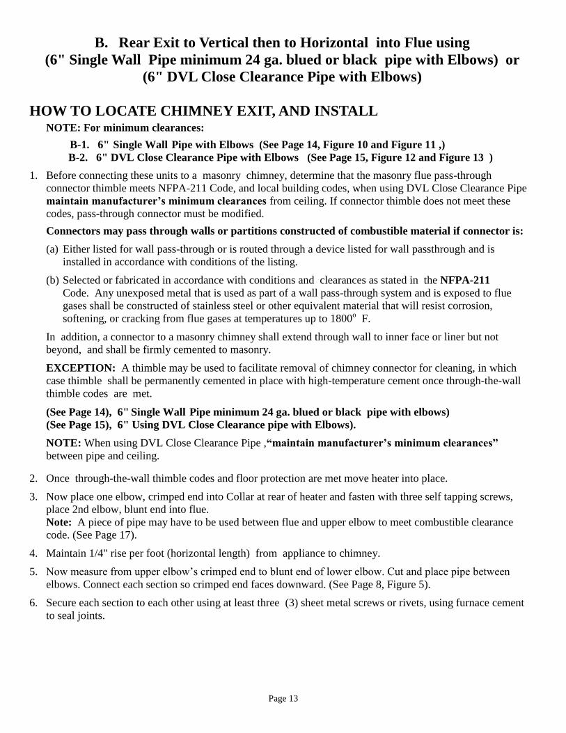
B. Rear Exit to Vertical then to Horizontal into Flue using (6" Single Wall Pipe minimum 24 ga. blued or black pipe with Elbows) or
(6" DVL Close Clearance Pipe with Elbows) HOW TO LOCATE CHIMNEY EXIT, AND INSTALL
NOTE: For minimum clearances:
B- 1. 6" Single Wall Pipe with Elbows (See Page 14, Figure 10 and Figure 11 ,) B-2. 6" DVL Close Clearance Pipe with Elbows (See Page 15, Figure 12 and Figure 13 )
1. Before connecting these units to a masonry chimney, determine that the masonry flue pass-through connector thimble meets NFPA-211 Code, and local building codes, when using DVL Close Clearance Pipe maintain manufacturer’s minimum clearances from ceiling. If connector thimble does not meet these codes, pass-through connector must be modified.
Connectors may pass through walls or partitions constructed of combustible material if connector is:
(a) Either listed for wall pass-through or is routed through a device listed for wall passthrough and is installed in accordance with conditions of the listing.
(b) Selected or fabricated in accordance with conditions and clearances as stated in the NFPA-211 Code. Any unexposed metal that is used as part of a wall pass-through system and is exposed to flue gases shall be constructed of stainless steel or other equivalent material that will resist corrosion, softening, or cracking from flue gases at temperatures up to 1800o F.
In addition, a connector to a masonry chimney shall extend through wall to inner face or liner but not beyond, and shall be firmly cemented to masonry.
EXCEPTION: A thimble may be used to facilitate removal of chimney connector for cleaning, in which case thimble shall be permanently cemented in place with high-temperature cement once through-the-wall thimble codes are met.
(See Page 14), 6" Single Wall Pipe minimum 24 ga. blued or black pipe with elbows) (See Page 15), 6" Using DVL Close Clearance pipe with Elbows).
NOTE: When using DVL Close Clearance Pipe ,“maintain manufacturer’s minimum clearances”
between pipe and ceiling.
2. Once through-the-wall thimble codes and floor protection are met move heater into place.
3. Now place one elbow, crimped end into Collar at rear of heater and fasten with three self tapping screws, place 2nd elbow, blunt end into flue. Note: A piece of pipe may have to be used between flue and upper elbow to meet combustible clearance code. (See Page 17).
4. Maintain 1/4" rise per foot (horizontal length) from appliance to chimney.
5. Now measure from upper elbow’s crimped end to blunt end of lower elbow. Cut and place pipe between
elbows. Connect each section so crimped end faces downward. (See Page 8, Figure 5).
6. Secure each section to each other using at least three (3) sheet metal screws or rivets, using furnace cement to seal joints.
Page 14
CEILING
CLEAN OUT DOOR
MASONRY FLUE LINERS
MASONRY CHIMNEY
(6” Single Wall pipe minimum
24 ga blued or black pipe)
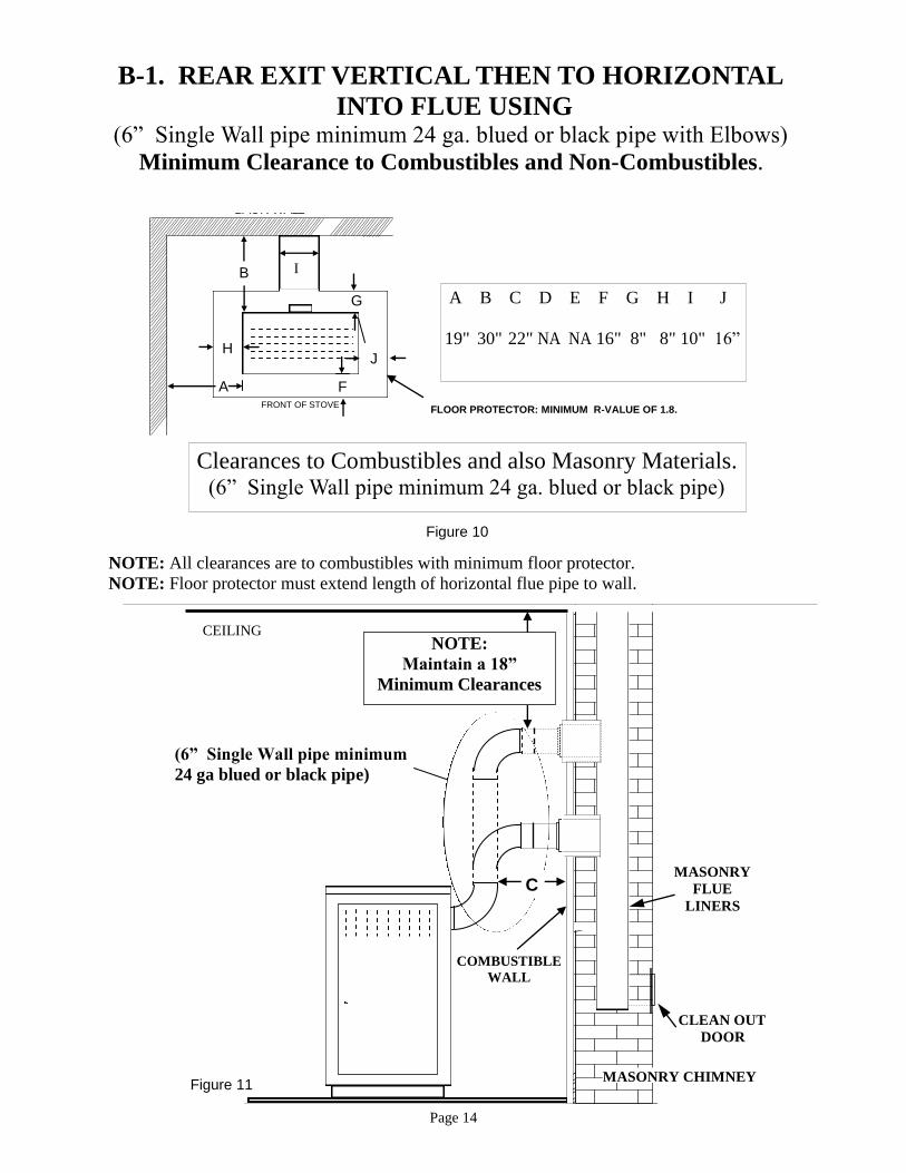
NOTE: Maintain a 18”
Minimum Clearances
COMBUSTIBLE WALL
Figure 11
C
B-1. REAR EXIT VERTICAL THEN TO HORIZONTAL INTO FLUE USING
(6” Single Wall pipe minimum 24 ga. blued or black pipe with Elbows) Minimum Clearance to Combustibles and Non-Combustibles.
NOTE: All clearances are to combustibles with minimum floor protector. NOTE: Floor protector must extend length of horizontal flue pipe to wall.
BACK WALL
SID
E W
AL
L
A
E
BF
C C
D
G
FRONT OF STOVE
G
H
F
I
A
B
Clearances to Combustibles and also Masonry Materials. (6” Single Wall pipe minimum 24 ga. blued or black pipe)
A B C D E F G H I J 19" 30" 22" NA NA 16" 8" 8" 10" 16”
Figure 10
J
FLOOR PROTECTOR: MINIMUM R-VALUE OF 1.8.

Page 15
DVL CLOSE CLEARANCE PIPE
CEILING
CLEAN OUT DOOR
MASONRY FLUE LINERS
MASONRY CHIMNEY
NOTE: Maintain Manufacturer’s
Minimum Clearances
COMBUSTIBLE WALL
Figure 13
C
B-2. REAR EXIT VERTICAL THEN TO HORIZONTAL INTO MASONRY FLUE USING
(6" DVL Close Clearance pipe with Elbows) Minimum Clearance to Combustibles and Non-Combustibles.
NOTE: All clearances are to combustibles with minimum floor protector. NOTE: Floor protector must extend length of horizontal flue pipe to wall.
BACK WALL
SID
E W
AL
L
A
E
BF
C C
D
G
FRONT OF STOVE
G
H
F
I
A
B
Clearances to Combustibles and also Masonry Materials. (6" DVL Close Clearance pipe)
A B C D E F G H I J 16" 22" 14" NA NA 16" 8" 8" 10" 16”
Figure 12
J
FLOOR PROTECTOR: MINIMUM R-VALUE OF 1.8.

Page 16
C. Rear exit into Masonry Fireplace using (6" Single Wall pipe, minimum 24 ga. blued or black pipe)
HOW TO LOCATE CHIMNEY EXIT, AND INSTALL
NOTE: For minimum clearances (See Page 17, Figure 14 and Figure 15 ) .
INSTALLATION PREPARATION
1. Relocate furniture and other materials away from front of fireplace to allow free access to fireplace.
2. Thoroughly clean fireplace or flue of ashes and soot.
3. Check chimney and smoke chamber for excessive buildup of creosote or soot. Also, check for obstructions, such as birds nests. If chimney is excessively dirty, clean it, or have someone clean it professionally BEFORE installing or using room heater.
4. If fireplace has an ash dump or outside air provision, these must be sealed off with metal or tightly packed non-combustible insulation to prevent cold air from entering fireplace chamber.
5. Remove or wire open fire place damper. (See Page 17)
6. A noncombustible sealing plate must be installed to close and seal opening of fireplace. A hole, diameter of pipe used, must be cut into the sealing plate to faciltate a place for stove pipe to go through into fireplace flue. Note: Pipe must go above the damper 2” to have proper flow. (See Page 17, Figure 15)
7. Once all codes are met and stove is in proper location, measure from back of stove to center of flue and cut pipe accordingly. Simply connect Single Wall Pipe (minimum 24 ga. blued or black pipe) per chimney manufacturer’s instructions.
(a) Maintain 1/4" rise per foot (horizontal length) from the appliance to the chimney.
(b) Connect each section so crimped end faces towards stove.
(c) Secure each section to each other using at least three (3) sheet metal screws or rivets, using furnace cement to seal joints.
(d) Use three (3) sheet metal screws to fasten pipe to collar on rear of heater.

Page 17
Remo
C. REAR EXIT INTO MASONRY FIREPLACE USING (6” Single Wall pipe minimum 24 ga. blued or black pipe)
Minimum Clearance to Combustibles.
NOTE: All clearances are to combustibles with minimum floor protector. NOTE: Floor protector must extend length of horizontal flue pipe to wall.
( NOTE: ) MINIMUM CLEARANCES FROM
TOP OF UNIT TO MANTEL OR MANTEL SUPPORTS 21" MINIMUM
SEALING PLATE
SINGLE WALL PIPE
8"
29"
HEARTH
Figure 15
min. 2” D
BACK WALL
SID
E W
AL
L
A
E
BF
C C
D
G
FRONT OF STOVE
G
H
F
I
A
B
Figure 14
MANTLE
SIDE TRIM
E
J
FLOOR PROTECTOR: MINIMUM R-VALUE OF 1.8.

Page 18
D. Rear Exit to Vertical Ceiling Exit using (6" Single Wall minimum 24 ga. blued or black pipe with Elbow) or
(6" DVL Close Clearance Pipe with Elbow) and any (Listed 2100° UL 103 HT Chimney)
PREPARING ROOM HEATER LOCATION
1. Select an installation location that will give best airflow from front of heater to remainder of the home.
2. Place protective floor pad in position.
3. Place unit on pad making sure minimum clearance specifications are met. NOTE: This model is designed for connection to any Listed 2100° UL 103 HT. TYPE chimney, also any Listed UL DVL Close Clearance Pipe or Shielded Single wall Pipe. Follow pipe manufacturer’s
instructions carefully.
CHIMNEY This room heater must be converted to (1) a chimney complying with requirements for Type HT chimneys in the Standard for Chimneys, Factory-Built, Residential, Type and Building Heating Appliance, UL 103, or (2) a code approved masonry chimney with flue liner.
HOW TO LOCATE CHIMNEY EXIT, AND INSTALL
NOTE: For minimum clearances (See Page 19, Figure 16 and Figure 17 ) .
1. Suspend a plumb bob from ceiling above unit so that the weight is hanging in center of the flue exit. (A small weight on a string will serve as a plumb bob.) Mark ceiling where string is suspended to locate center of chimney hole.
2. After locating center of hole, install ceiling support box, chimney or chimney connector, flashing, and rain cap per chimney manufacturer’s instructions, and local building codes for installation
through combustible walls or ceilings.
3. Now connect stove and ceiling support box using minimum #24 ga. blued or black steel connector pipe (DO NOT USE GALVANIZED PIPE) or DVL Close Clearance pipe. Connect each section so crimped end faces downward, and secure each section to each other using at least three (3) sheet metal screws or rivets, using furnace cement to seal joints. Single wall pipe is to be connected with (3) sheet metal screws or rivets to collar on rear of heater. ( See Page 19)
CAUTION: Certain installation types require the use of certain chimney types. Please follow these instructions exactly.

Page 19
BACK WALL
SID
E W
AL
L
A
E
BF
C C
D
G
FRONT OF STOVE
G
H
F
I
A
B
D. REAR EXIT TO VERTICAL CEILING EXIT USING (6” Single Wall pipe minimum 24 ga. blued or black pipe with Elbow) or
(6" DVL Close Clearance pipe with Elbow) Minimum Clearance to Combustibles.
Clearances to Combustibles and also Masonry Materials. (6” Single Wall pipe minimum 24 ga. blued or black pipe)
A B C D E F G H I J
19" 30" 22" NA NA 16" 8" 8" 10" 16”
Clearances to Combustibles and also Masonry Materials.
(6" DVL Close Clearance pipe)
A B C D E F G H I J
16" 22" 14" NA NA 16" 8" 8" 10" 16”
NOTE: All clearances are to combustibles with minimum floor protector. NOTE: Floor protector must extend length of horizontal flue pipe to wall.
Figure 16
J
FLOOR PROTECTOR: MINIMUM R-VALUE OF 1.8.
C
Figure 17
6” Single Wall Pipe
LISTED 2100° UL 103 HT TYPE CHIMNEY ASSEMBLY REFER
TO MANUFACTURER’S INSTALLATION INSTRUCTIONS

Page 20
E. Rear Exit Through Wall, Exterior Chimney Outside Residence using (6" Single Wall pipe minimum 24 ga. blued or Black pipe) or
(6" DVL Close Clearance Pipe) and any (Listed 2100° UL. HT chimney and Listed 2100° UL HT T-Box assembly)
PREPARING ROOM HEATER LOCATION
1. Select an installation location that will give best airflow from front of heater to remainder of the home.
2. Place protective floor pad in position.
3. Place unit on pad making sure minimum clearance specifications are met. NOTE: This model is designed for connection to any Listed 2100° UL 103 HT. TYPE chimney, also any Listed UL DVL Close Clearance Pipe or Shielded Single wall Pipe. Follow pipe manufacturer’s instructions
carefully.
CHIMNEY This room heater must be converted to (1) a chimney complying with requirements for Type HT chimneys in the Standard for Chimneys, Factory-Built, Residential, Type and Building Heating Appliance, UL 103, or (2) a code approved masonry chimney with flue liner.
HOW TO LOCATE CHIMNEY EXIT, AND INSTALL
NOTE: For minimum clearances (See Page 21, Figure 18 and Figure 19 ).
1. Mark plumb line on wall directly behind center of heater. (See Page 21)
2. Place horizontal portion of heater pipe in position and project a point onto plumb line level with center of plumb line.
3. Measure up so there will be at least 1/4" rise per foot of horizontal connector pipe. This will give you the center of the hole for chimney penetration.
4. After locating center of penetration, install tee-box and chimney as per chimney manufacturer's specifications.
5. Connect chimney collar to tee-box using #24 ga. minimum blued or black steel connector pipe or DVL Close Clearance pipe. DO NOT use galvanized pipe. Connect each section so crimped end faces downward, and secure each section to each other using three (3) sheet metal screws or rivets, using furnace cement to seal joints. Single wall pipe is to be connected with (3) sheet metal screws or rivets to collar on rear of heater. ( See Page 21)
CAUTION: Certain installation types require the use of certain chimney types. Please follow these instructions exactly.

Page 21
NOTE: All clearances are to combustibles with minimum floor protector. NOTE: Floor protector must extend length of horizontal flue pipe to wall.
BACK WALL
SID
E W
AL
L
A
E
BF
C C
D
G
FRONT OF STOVE
G
H
F
I
A
B
E. REAR EXIT THROUGH WALL, EXTERIOR CHIMNEY OUTSIDE RESIDENCE USING
(6” Single Wall pipe minimum 24 ga. blued or black pipe) or (6" DVL Close Clearance pipe) and any
(Listed 2100 UL HT Chimney and. Listed 2100 UL HT T-Box assembly) Minimum Clearance to Combustibles.
Clearances to Combustibles and also Masonry Materials. (6” Single Wall pipe minimum 24 ga. blued or black pipe)
A B C D E F G H I J
19" 30" NA NA NA 16" 8" 8" 10" 16”
Clearances to Combustibles and also Masonry Materials. (6" DVL Close Clearance pipe)
A B C D E F G H I J
16" 22" NA NA NA 16" 8" 8" 10" 16”
Figure 18
J
FLOOR PROTECTOR: MINIMUM R-VALUE OF 1.8.
Combustible ceiling
Combustible wall
Chimney connector
Figure 19
LISTED 2100° UL 103 HT TYPE CHIMNEY T-BOX ASSEMBLY
AND CHIMNEY REFER TO MANUFACTURER’S
INSTALLATION INSTRUCTIONS

Page 22
* Note: The above diagram illustrates dimensions for clearances. The stove you are installing may or may not match the stove shown in the illustration.
ALTERNATIVES FOR WALL PROTECTION
NOTE: THIS UNIT IS NOT APPROVED FOR MOBILE HOME USE.
REDUCED WALL CLEARANCES
The National Fire Protection Association (NFPA) Standard 211 recognizes eight (8) Wall Protection Systems. The following are two samples we suggest:
A. Galvanized steel sheet metal with minimum thickness of 24 gauge. B. 4" nominal thickness brick. Either of these materials must be spaced 1" from the wall surface. With sheet metal, non-combustibles are used to maintain the 1" air space. With a brick wall, metal ties are used to anchor the brick to the wall and maintain the 1" air space. To avoid excessive heat transmission, the spacers or wall ties should not be placed directly behind the heater or chimney connector. The 1" space provides free air circulation. For best insulating results, it is essential that there are openings completely around the system, including the bottom, so that cool air can circulate the 1" air space. The clearance reduction system should extend 13" beyond the heater in height and width. If must extend as high as the thimble penetration of the wall to the chimney to protect the wall behind the vertical run of the chimney connector (See Figure 17 on Page 19).
WARNING: Never install the stove in locations where gasoline, kerosene, charcoal lighter or any other flammable liquids are used or stored.
Figure 20

Page 23
The connector and/or chimney should be inspected at least once a month during the heating season to determine if a creosote buildup has occurred.
CAUTION THE UNIT IS PAINTED WITH A SPECIALLY FORMULATED HIGH TEMPERATURE PAINT THAT CURES DURING THE FIRST TWO OR THREE FIRINGS. YOU MAY NOTICE A SLIGHT SMOKING EFFECT AND AN ODOR OF BURNING PAINT WHEN YOU BUILD THE FIRST FIRES. THIS IS NORMAL AND IS NOT A CAUSE FOR ALARM. IN SOME CASES, THESE FUMES WILL ACTIVATE A SMOKE ALARM. OPENING A WINDOW NEAR THE UNIT WILL ALLOW THESE FUMES TO ESCAPE. DO NOT BUILD A LARGE, ROARING FIRE UNTIL THIS CURING IS COMPLETE OR THE HEATER FINISH MAY BE DAMAGED.
CAUTION
NEVER USE GASOLINE, GASOLINE-TYPE LANTERN FUEL, KEROSENE, CHARCOAL LIGHTER FLUID OR SIMILAR LIQUIDS TO START OR "FRESHEN UP" A FIRE IN THE HEATER. KEEP ALL SUCH LIQUIDS WELL AWAY FROM THE STOVE WHEN IT IS IN USE. ALL FLUIDS OF THIS TYPE GIVE OFF VOLATILE FUMES AND CAN AND WILL EXPLODE! DON'T TAKE A CHANCE WITH THE SAFETY OF YOUR HOME AND FAMILY.
CAUTION
CREOSOTE AND SOOT
The Combo Coal & Wood Stove has been designed to burn coal. This conforms to United States Government Protection Agency regulations for coal stoves. NOTE: A draft reading of ..025 W.C. is suggested for proper burning of this unit when
using bituminous coal as fuel. When using anthracite coal, this draft reading is a minimum reading.
As a wood burning unit, the Combo Coal & Wood Stove is EPA Exempt. per Method 28.
When the unit is burned, the products of combustion combined with moisture to form soot residue. This residue accumulates on the flue lining. When ignited, this soot creates an extremely hot fire. Your chimney and chimney connector should be inspected once every two months. Any build up of soot should be removed to prevent the risk of a chimney fire.

Page 24
CAUTION: For safe and proper operation according to the United States Environmental Protection Agency regulations for wood stoves, you must use the proper air slide adjuster plate with the proper fuel you intend to burn.
WOOD AIR SLIDE ADJUSTER PLATE NOTCH TO BOTTOM AIR SLIDE ADJUSTER PLATE KNOB
WOOD AIR SLIDE ADJUSTER PLATE
CLOSED
OPERATION FOR BURNING WOOD FUEL
WOOD AIR SLIDE ADJUSTER PLATE NOTCH TO BOTTOM AIR SLIDE ADJUSTER PLATE KNOB
WOOD AIR SLIDE ADJUSTER PLATE WITH NOTCH
OPEN
SIDE VIEW OF CAST ASH DOOR AND INSTALLED
WOOD AIR SLIDE ADJUSTER PLATE

Page 25
TO START A FIRE USING WOOD FUEL.
NOTE: The manufacturer recommends that for maximum performance, burn natural seasoned hard wood.
1. Open air draft by loosening the AIR SLIDE ADJUSTER PLATE KNOB on ash door to the “Open” position. (SEE PAGE 24)
2. Open feed door and place up to six (6) sheets of crumbled newspaper on top of shaker grates.
3. Place a layer of kindling wood or charcoal on top of newspaper. Allow air space between the pieces of wood or charcoal.
4. Light paper and close fuel door.
5. Wood: After lighting kindling and embers and a coal bed have been established, load the heater with wood.
6. Repeat this process until the firebox is filled. NEVER fill box over top of fire brick.
7. Reduce the air control on ash door to your desired comfort zone. Never leave the feed door of the stove open longer than necessary when refueling. This will prevent noxious gases escaping from the stove. AIR INTAKE SETTING
Draft controls on ash door should be open less than halfway for most efficient operation of the stove. The fully “OPEN” position should only be used when starting a fire or short periods of time after adding more
fuel. Never leave the ash door open for longer than necessary to remove the ash pan or to replace it.
NOTE: Never use gasoline, gasoline type lantern fuel, kerosene, charcoal lighter fluid, or any similar flammable liquid in your stove to start or “freshen up the fire.” Keep all
such materials away from the stove during use.
NOTE: THE FUELING AND ASH REMOVAL DOORS MUST REMAIN CLOSED WHEN IN OPERATION.

Page 26
OPERATION FOR BURNING COAL FUEL
The Combo Coal & Wood Stove Comes with Wood Air Slide Adjuster Plate installed. You must change the Wood Air Slide Adjuster Plate inside of the front cast ash door to use the Combo Coal & Wood Stove unit for burning coal.
CHANGING WOOD AIR SLIDE ADJUSTER PLATE TO COAL AIR SLIDE ADJUSTER PLATE
1. Find the coal air slide adjuster plate package inside the fire box and remove. Open contents (SEE BELOW)
2. Open the front cast ash door and remove the wood air slider adjuster plate from inside of door, by unscrewing the air slide adjuster knob. (SEE BELOW). Note there is NO NOTCH in the coal air slide adjuster plate. Place the coal air slide adjuster plate in place of the wood slide adjuster plate and replace air slide adjuster knob. You are now ready to safely use the Combo Coal & Wood Stove to burn coal.
AIR SLIDE ADJUSTER PLATE KNOB
COAL AIR SLIDE ADJUSTER PLATE
CLOSED
AIR SLIDE ADJUSTER PLATE KNOB
COAL AIR SLIDE ADJUSTER PLATE
OPEN
SIDE VIEW OF CAST ASH DOOR AND
INSTALLED COAL AIR SLIDE
ADJUSTER PLATE
CAUTION: For safe and proper operation according to the United States Government Protection Agency regulations for coal stoves, you must use the proper air slide adjuster plate with the proper fuel you intend to burn.

Page 27
TO START A FIRE USING COAL FUEL The Combo Coal & Wood Stove is designed to burn a variety of coals. Because of it’s high carbon content and
smokeless combustion, Bituminous or Anthracite (hard) coal is the preferred fuel. The best size coal for this unit is chestnut size. We recommend storage of coal in a dry cool place away from flames.
1. Open air draft by loosening the AIR SLIDE ADJUSTER PLATE KNOB on ash door to the “Open” position. (SEE PAGE 26)
2. Open feed door and place up to six (6) sheets of crumbled newspaper on top of shaker grates.
3. Place a layer of kindling wood or charcoal on top of newspaper. Allow air space between the pieces of wood or charcoal.
4. Light paper and close fuel door.
5. Coal: After Lighting kindling and embers and a coal bed have been established, load the heater with coal.
6. Repeat this process until the firebox is filled. NEVER fill box over top of fire brick.
7. Reduce the air control on ash door to your desired comfort zone. Never leave the feed door of the stove open longer than necessary when refueling. This will prevent nox-ious gases escaping from the stove. AIR INTAKE SETTING
Draft controls on ash door should be open less than halfway for most efficient operation of the stove. The fully “OPEN” position should only be used when starting a fire or short periods of time after adding more
fuel. Never leave the ash door open for longer than necessary to remove the ash pan or to replace it.
NOTE: Never use gasoline, gasoline type lantern fuel, kerosene, charcoal lighter fluid, or any similar flammable liquid in your stove to start or “freshen up the fire.” Keep all
such materials away from the stove during use.
NOTE: THE FUELING AND ASH REMOVAL DOORS MUST REMAIN CLOSED WHEN IN OPERATION.
Page 28
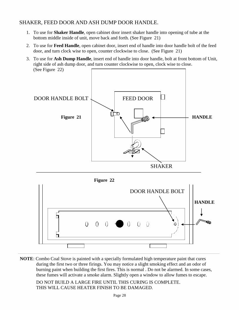
SHAKER, FEED DOOR AND ASH DUMP DOOR HANDLE.
1. To use for Shaker Handle, open cabinet door insert shaker handle into opening of tube at the bottom middle inside of unit, move back and forth. (See Figure 21)
2. To use for Feed Handle, open cabinet door, insert end of handle into door handle bolt of the feed door, and turn clock wise to open, counter clockwise to close. (See Figure 21)
3. To use for Ash Dump Handle, insert end of handle into door handle, bolt at front bottom of Unit, right side of ash dump door, and turn counter clockwise to open, clock wise to close. (See Figure 22)
NOTE: Combo Coal Stove is painted with a specially formulated high temperature paint that cures
during the first two or three firings. You may notice a slight smoking effect and an odor of burning paint when building the first fires. This is normal . Do not be alarmed. In some cases, these fumes will activate a smoke alarm. Slightly open a window to allow fumes to escape.
DO NOT BUILD A LARGE FIRE UNTIL THIS CURING IS COMPLETE. THIS WILL CAUSE HEATER FINISH TO BE DAMAGED.
Figure 21
SHAKER
DOOR HANDLE BOLT FEED DOOR
HANDLE
DOOR HANDLE BOLT
HANDLE
Figure 22

Page 29
MAINTAINING A FIRE After a fire has been started in your Combo Coal & Wood Stove, it is possible to keep it burning for long periods of time. Simply use a minimum draft setting. Normally, you should remove the ashes and refuel twice a day. As the ash builds up, it is necessary to periodically remove it to make room for more fuel and to allow an unrestricted flow of air through the fuel bed. After removing the ashes, replenish the coal.
ASH REMOVAL (SHAKING)
Insert shaker handle rod through the tube which protrudes from the side of the stove through the restraint channel. Move handle up and down, keeping the end in the restraint channel to prevent moving the grate system too far and accidentally dumping the fire. Ash will fall into the ash pan underneath the grates. Keep a 1-1/2” layer of ash on top to the grates. It is best to remove and empty the ash pan each time you "shake". Through extensive ash removal, a piece of unburned coal may lodge between two grates and prevent movement. If this occurs, do not try to force the handle. Damage to the grates may result. Lift the handle clear of the restraint channel and gently jiggle it loose. If this does not work, allow the stove to burn normally for an hour or two and the unburned coal will burn itself out. If you still have no success, lift the handle clear of the restraint channel and move the handle up and down, dumping a portion of the ash and fire into the ash pan. Use this procedure if you want to empty all of the ash and coal from the unit. ASH DISPOSAL 1. Place ashes in a metal container with a tight fitting lid. 2. Place the closed container in a non-combustible area. 3. Retain ashes in closed container until all cinders have thoroughly cooled before final disposal. OVERFIRING Do not overfire. Flammable liquids, wood or trash in the stove may cause overfiring. If the chimney connector or stove glows red, the stove is overfired. If this occurs, close stove damper and door. This will reduce air supply to the fire. A chimney fire may cause structural damage to the chimney. Do not use the stove until the chimney and chimney connector have been thoroughly inspected and damaged parts have been replaced. A chimney sweep can perform the inspection.

Page 30
ASSEMBLY BLOWER MOTOR (OPTIONAL)
Blower assembly must be disconnected from the source of electrical supply before attempting the installation. Blower assembly is attended for use only with Combo Coal & Wood Stove.
A. To attach optional blower motor to the rear of the unit ,place motor in blower opening at bottom rear shield, us-ing the two self tapping screw’s provided, screw, and secure to rear shield. (See Figure 23)
B. Remove thermostat cover. Take thermostat with wires and slide wires down between Cabinet Back and Rear Shield out through blower opening. Screw thermostat to rear shield with provided screws, and replace thermostat cover. (See Figure 23)
C. Take the wires coming out of the blower opening and put them through the upper hole in the motor cage. Attach the two ground wires underneath right motor screw. Connect the white wire from power cord to the white wire on the motor. Connect black wire from the power cord to a thermostat wire. Connect black motor wire to the other thermostat wire. Do not route power cord over or under the unit. (See Figure 23)
D. Center Motor Cage over motor and use the supplied self tapping screws to screw and secure motor to rear shield (See Figure 23). Do not route power cord over or under the unit.
POWER CORD WITH ROUND.
TWO THERMOSTAT WIRES GO THRU HERE
TWO THERMOSTAT WIRES
NOTE: AFTER MOUNTING MOTOR AND CONNECTING WIRING, CENTER MOTOR CAGE OVER MOTOR AND USE THE TWO SUPPLIED SELF TAPPING SCREWS TO SCREW AND SECURE MOTOR CAGE TO REAR FIRE BOX.
MOTOR
THERMOSTAT WITH WIRES
THERMOSTAT COVER CABINET BACK
REAR SHIELD
GROUND WIRE’S,
WHITE WIRE’S GO
TOGETHER
PUT MOTOR IN BEHIND REAR SHIELD AND CENTER, USE THE TWO PROVIDED SELF TAPPING SKEW'S TO SCREW AND SECURE MOTOR TO REAR SHIELD
TWO GROUND WIRE’S, SECURE BEHIND THIS SCREW.
MOTOR CAGE
SELF TAPPING SCREWS
DO NOT ROUTE POWER CORD OVER OR UNDER THE UNIT.
Figure 23
REAR FIRE BOX
SELF TAPPING SCREWS
SELF TAPPING SCREWS
THERMOSTAT
BLOWER ASSEMBLY # MA CCOAL714

Page 31
NEW BUCK CORPORATION (NBC) LIMITED WARRANTY
COMBO COAL & WOOD STOVE
PLEASE READ THIS WARRANTY CAREFULLY PRODUCTS COVERED This warranty covers the New Buck Stove heating unit, so long as it is owned by the original purchaser, including optional and standard accessories purchased at the same time, subject to terms, limitations, and conditions herein set out. PRODUCTS NOT COVERED Glass, Refractory Material, Firebrick or Gaskets. This warranty will also not cover any damage and/or failure caused by abuse or improper installation of the products covered. WARRANTY TIME PERIODS (A) Period 1
For one year from the date of purchase, NBC will replace or repair, at its option, any part defective in materials or workmanship. The cost of parts only are included. The customer pays any labor or transportation charges required. THEREAFTER;
(B) Period 2 For the period after the first year from the date of purchase and extending for 5 years as long as the Combo Coal & Wood Stove is owned by the original purchaser, NBC will repair or replace, at it’s option, any part defective in materials or workmanship, with the exception of :
electrical motors, wiring, switches, components, optional and standard accessories; and all parts not permanently attached to the heating units. Parts not permanently attached to the heating unit are defined as those items designed to be removed from the stove, including those removable with common hand tools. The costs of parts only are included. This customer pays any labor or transportation charges required.
Page 32
PROCEDURE Should you feel that your Combo Coal & Wood Stove is defective, you should contact any Combo Coal & Wood Stove dealer for the name of your nearest authorized Combo Coal & Wood Stove service representative, who will instruct you on the proper procedure, depending on which Warranty Time Period (Period 1 or Period 2) applies. If for any reason you are dissatisfied with the suggested procedures, you may contact us in writing at:
New Buck Corporation P. O. Box 69
200 Ethan Allen Drive Spruce Pine, NC 28777
Email: [email protected] CONDITIONS AND EXCLUSIONS (A) Replacement of parts may be in the form of new or fully reconditioned parts, at NBC's option.
(B) There is no other express warranty. All implied warranties or merchantability and fitness for
use are limited to the duration of the Express Warranty.
(C) New Buck Corporation is not liable for indirect, incidental, or consequential damages in connection with the use of the product including any cost or expense of providing substitute equipment or service during periods of malfunction or non-use. Some states do not allow the exclusion of incidental or consequential damages, so the above exclusion may not apply to you.
(D) All warranty repairs under this warranty must be performed by an authorized Combo Coal & Wood Stove service representative. Repairs or attempted repairs by anyone other than an authorized Combo Coal & Wood Stove service representative are not covered under this warranty. In addition, these unauthorized repairs may result in additional malfunctions, which is not covered by the warranty.
OTHER RIGHTS This warranty gives you specific legal rights and you may also have other rights which vary from state to state.
OWNER REGISTRATION CARD
The attached owner registration card must be completed in its entirety and mailed within 30 days from the date of installation in order for warranty coverage to begin to:
New Buck Corporation P. O. Box 69 200 Ethan Allen Drive Spruce Pine, NC 28777
Email: [email protected] PLEASE NOTE: The Owner Registration Card must contain the Authorized Combo Coal & Wood Stove Dealer Number and the Certified Installer's number (if applicable) for warranty coverage to begin. NAME ____________________________________________________________ ADDRESS _________________________________________________________ CITY ______________________ S TAT E ______________ ZIP _____________ CUSTOMER EMAIL: ________________________________________________ MODEL # __________________ SERIAL # _________________ DATE OF INSTALLATION ______________ INSTALLER'S NAME _______________________________________________