Embed Size (px)
Citation preview

COMBIVERT
Original manualMat.No. Rev.00F50EB-KG00 1C
GB Instruction Manual Housing G7.5...11 kW 230 V
7.5...22 kW 400 V


GB - 3
Table of Contents
1. Preface ..............................................................................................................51.1 General ................................................................................................................................. 51.2 Safety instructions .............................................................................................................. 51.3 Validity and liability ............................................................................................................. 51.4 Copyright .............................................................................................................................. 61.5 Specifiedapplication ........................................................................................................... 61.6 Product description ............................................................................................................. 71.7 Unitidentification ................................................................................................................ 81.8 Installation instructions ...................................................................................................... 91.8.1 Cooling systems .................................................................................................................... 91.8.2 Control cabinet installation ................................................................................................... 101.9 Safety and operating instructions .....................................................................................11
2. Technical Data ...............................................................................................122.1 Operating conditions ......................................................................................................... 122.2 Technical data of the 230V class ...................................................................................... 132.3 Technical data of the 400 V class ..................................................................................... 142.4 DC supply ........................................................................................................................... 152.4.1 Calculation of the DC input current ...................................................................................... 152.4.2 Internal input circuit .............................................................................................................. 152.5 Dimensions and weights ................................................................................................... 162.6 Terminal strips of the power circuit ................................................................................. 222.6.1 Permissible cable cross-sections and tightening torques of the terminals .......................... 222.7 Accessories ........................................................................................................................ 232.7.1 Filter and chokes ................................................................................................................. 232.8 Connection Power Unit ..................................................................................................... 242.8.1 Mains and motor connection ................................................................................................ 242.8.2 Selection of the motor cable ................................................................................................ 252.8.3 Connection of the motor ...................................................................................................... 252.8.3.1 Motor cable length for parallel operation of motors ............................................................. 252.8.4 Temperature detection T1, T2 .............................................................................................. 262.8.4.1 Use of the temperature input in KTY mode ......................................................................... 272.8.4.2 Use of the temperature input in PTC mode ......................................................................... 272.8.5 Connection of a braking resistor .......................................................................................... 282.8.5.1 Braking resistor without temperature monitoring ................................................................. 282.8.5.2 Braking resistor with over-heat protection and GTR7 monitoring ........................................ 292.8.5.3 Braking resistor with over-heat protection without GTR7 monitoring ................................... 30
Annex A .....................................................................................................................31A.1 Overload characteristic ..................................................................................................... 31A.2 Overload protection in the lower speed range ............................................................... 31A.3 Calculation of the motor voltage ...................................................................................... 32A.4 Shut down .......................................................................................................................... 32A.4.1 Maintenance ........................................................................................................................ 32A.4.2 Storage ................................................................................................................................ 33A.4.3 Cooling circuit ...................................................................................................................... 33

GB - 4
Table of Contents
A.4.4 Fault correction .................................................................................................................... 33A.4.5 Disposal ............................................................................................................................... 33
Annex B .....................................................................................................................34B.1 Certification ........................................................................................................................ 34B.1.1 CE Marking .......................................................................................................................... 34B.1.2 UL Marking........................................................................................................................... 34Maximum Surrounding Air Temperature 45 °C (113 °F) .............................................................. 34
Annex C .....................................................................................................................37C.1 Installation of water-cooled units ..................................................................................... 37C.1.1 Heat sink and operating pressure ........................................................................................ 37C.1.2 Materials in the cooling cicuit ............................................................................................... 37C.1.3 Requirements on the coolant ............................................................................................... 38C.1.4 Connection to the cooling system ........................................................................................ 39C.1.5 Coolant temperature and moisture condensation ................................................................ 39C.1.6 Coolantheatingdependingonpowerlossandflowratewithwater .................................... 41C.1.7 Typicallyfallofpressuredependingontherateofflow ....................................................... 41
Annex D .....................................................................................................................42D.1 Changing the response threshold of the braking transistor ......................................... 42

GB - 5
Preface
1. Preface1.1 General
First we would like to welcome you as a customer of the company Karl E. Brinkmann GmbH and congratulation to the purchase of this product. You have decided for a product on highest technical level.
The described hard- and software are developments of the Karl E. Brinkmann GmbH. The enclosed documents correspond to conditions valid at printing. Misprint, mistakes and tech-nical changes reserved.
The instruction manual must be made available to the user. Before working with the unit the user must become familiar with it. This especially applies to the knowledge and observance of the following safety and warning indications. The pictographs used in this instruction man-ual have following meaning:
Danger Is used, if life or health of the user is in danger or if substantial damage to property can occur.Warning
Caution
Attention Is used, if a measure is necessary for safe and trouble-free operation.observe at
all costs
Information Isused,ifameasuresimplifiesthehandlingoroperationofthe unit.Aid
Tip
1.2 Safety instructions
Observe safety and operating instruc-tions
Precondition for all further steps is the knowledge and obser-vance of the safety -, EMC- and operating instructions (Part 1 „Before Starting“ 0000NEB-0000“). This instruction is provid-ed with the unit or by download of www.keb.de.
Non-observance of the safety instructions leads to the loss of any liability claims. The safety andwarninginstructionsspecifiedinthismanualdonotlayclaimoncompleteness.Thislistis not exhaustive.
1.3 Validity and liabilityThe use of our units in the target products is outside of our control and therefore lies exclusively in the area of responsibility of the machine manufacturer.Theinformationcontainedinthetechnicaldocumentation,aswellasanyuser-specificadvicein spoken and written and through tests, are made to best of our knowledge and information about the application. However, they are considered for information only without responsibil-ity. This also applies to any violation of industrial property rights of a third-party.
Selection of our units in view of their suitability for the intended use must be done generally by the user.

GB - 6
Preface
Tests can only be done within the application by the machine manufacturer. They must be repeated,evenifonlypartsofhardware,softwareortheunitadjustmentaremodified.
Unauthorised opening and tampering may lead to bodily injury and property damage and may entail the loss of warranty rights. Original spare parts and authorized accessories by the manufacturer serve as security. The use of other parts excludes liability for the consequences arising out of.
Thesuspensionofliabilityisespeciallyvalidalsoforoperationinterruptionloss,lossofprofit,datalossorotherdamages.Thisisalsovalid, ifwereferredfirsttothepossibilityofsuchdamages.
If single regulations should be or become void, invalid or impracticable, the effectivity of all other regulations or agreements is not affected.
1.4 CopyrightThe customer may use the instruction manual as well as further documents or parts from it for internal purposes. Copyrights are with KEB and remain valid in its entirety. All rights reserved.
KEB®, COMBIVERT®, KEB COMBICONTROL® and COMBIVIS® are registered trade-marks of Karl E. Brinkmann GmbH.
Other wordmarks or/and logos are trademarks (TM) or registered trademarks (®) of their respectiveownersandarelistedinthefootnoteonthefirstoccurrence.Whencreatingourdocuments we pay attention with the utmost care to the rights of third parties. Should we have not marked a trademark or breach a copyright, please inform us in order to have the possibility of remedy.
1.5 SpecifiedapplicationThe KEB COMBIVERT serves exclusively for stepless open loop / closed-loop speed control of three-phase a.c. motors.
The operation of other electric consumers is prohibited and can lead to the de-struction of the unit.
The used semiconductors and components of KEB are developed and dimensioned for the use in industrial products. If the KEB COMBIVERT is used in machines, which work under exceptional conditions or if essential functions, life-supporting measures or an extraordinary safetystepmustbefulfilled,thenecessaryreliabilityandsecuritymustbeensuredbythemachine builder. The operation of the KEB COMBIVERT outside the indicated limit values of the technical data leads to the loss of any liability claims.
Units with safety function are limited to a service life of 20 years. The units must be changed after this time.

GB - 7
Preface
1.6 Product descriptionThis instruction manual describes the power circuits of the following units:
Unit type: Frequency inverterSeries: COMBIVERT F5/F6Power range: 13...19 kVA / 230 V class
11... 35 kVA / 400 V classHousing size: GVersion: air and water-cooled
Features of the power circuits:
• only slight switching losses due to IGBT• low noise development due to high switching frequency• extensive safety device for current, voltage and temperature• voltage and current monitoring in static and dynamic operation• conditionally short circuit proof and earth-fault proof• hardware current limit• integrated cooling fan

GB - 8
Preface
1.7 Unitidentification18 F5 K 1 G-3 4 0 F
Cooling0, 5, A, F Heat sink (standard)1, B, G Flat rear2, C, H Water cooling3, D, I Convection
Encoder interface0:none
Switching frequency; short time current limit; overcurrent limit0 2 kHz; 125 %; 150 % 5 4 kHz; 150 %; 180 % A 8 kHz; 180 %; 216 % F 16 kHz; 200 %; 240 %1 4 kHz; 125 %; 150 % 6 8 kHz; 150 %; 180 % B 16 kHz; 180 %; 216 % G 2 kHz; 400 %; 480 %2 8 kHz; 125 %; 150 % 7 16 kHz; 150 %; 180 % C 2 kHz; 200 %; 240 % H 4 kHz; 400 %; 480 %3 16 kHz; 125 %; 150 % 8 2 kHz; 180 %; 216 % D 4 kHz; 200 %; 240 % I 8 kHz; 400 %; 480 %4 2 kHz; 150 %; 180 % 9 4 kHz; 180 %; 216 % E 8 kHz; 200 %; 240 % K 16 kHz; 400 %; 480 %
Inputidentification0 1ph 230 V AC/DC 5 400 V class DC A 6ph 400 V AC1 3ph 230 V AC/DC 6 1ph 230 V AC B 3ph 600 V AC2 1/3ph 230 V AC/DC 7 3ph 230 V AC C 6ph 600 V AC3 3ph 400 V AC/DC 8 1/3ph 230 V AC D 600 V DC4 230 V class DC 9 3ph 400 V AC
Housing type A, B, D, E, G, H, R, U, W, P
Internal options (A...D with STO relay according to EN954-1/1997)0, A none1, B Braking transistor2, C integratedfilter3, D Brakingtransistorandintegratedfilter5, - only with braking transistor (with resistor monitoring)7, - withbrakingtransistor(withresistormonitoring)andintegratedEMCfilter
Control typeA APPLICATION K like A with safety technologyB BASIC (controlled frequency inverter)C COMPACT (controlled frequency inverter)E SCL P like E with safety technologyG GENERAL (controlled frequency inverter)H ASCL L like H with safety technology
MMULTI(regulated,field-orientedfrequencyinverterforthree-phaseasynchronousmo-tors)
S SERVO (regulated frequency inverter for synchronous motors)
Series F5/F6
Inverter size

GB - 9
General
1.8 Installation instructions
1.8.1 Cooling systemsThe KEB COMBIVERT F5/F6 is available for different cooling systems:
Heat sink with cooling fan (mounted version)The standard version is delivered with heat sink and cooling fan.
Special versionsThe dissipation of power loss must be guaranteed by the machine builder.
Flat rearThere is no heat sink at this version. The unit must be mounted on an appropriate ground for heat dissipation.
Water cooling
This version is dimensioned for the connection to an available cooling system. The dissipa-tion of the power loss must be ensured by the machine builder. In order to avoid moisture condensation, the minimum inlet temperature may not decrease the ambient temperature. The max. inlet temperature may not exceed 40°C. No aggressive coolant shall be used. Measures against contamination and calcination must be done externally. We recommend a pressure of 4 bar on the cooling system.
Convection (through-mount version)In this version the heat sink is placed externally with a cutout in the control cabinet.
CAUTION!
DO NOT TOUCH!Hot Surfaces
© 2005 KEB
In case of burn, cool inflicted area immediately and seek medical attention.
Heat sinks can reach temperatures, which can cause burns when touching. If in case of structural measures a direct contact cannot be avoided, a warning notice "hot surface" must be mounted at the machine.

GB - 10
General
1.8.2 Control cabinet installation
Mounting distances Dimen-sion
Distance in mm Distance in inch
C
A
B
DD
A 150 6B 100 4C 30 1.2D 0 0
X 1) 50 21) Distance to preceding elements in the cabinet door.
Direction of the cooling fins
Front and side view of the coolant inlet
Coolant outlet
Coolant inlet
See annex C for instructions of water-cooled units.

GB - 11
Safety instructions
1. GeneralIn operation, drive converter depending on their degree of protection, may have live, uninsulated and possibly also moving or rotating parts, as well as hot surfaces.In case of inadmissible removal of the required covers, of improper use, wrong installation or maloperation, there is the danger of serious personal injury and damage to property.For further information, see documentation.All operations serving transport, installation and commis-sioning as well as maintenance are to be carried out by skilled technical personnel (Observe IEC 364 or CENE-LEC HD 384 or DIN VDE 0100 and IEC 664 or DIN/VDE 0110 and national accident prevention rules!).For the purposes of these basic safety instructions, „skilled technical personnel“ means persons who are familiar with the installation, mounting, commissioning and operation oftheproductandhavethequalificationsneededfortheperformance of their functions.2.SpecifiedapplicationDrive converter are components which are intended for the installation in electric systems or machines.In case of installation in machinery, commissioning of the drive converter (i.e. the starting of normal operation) is prohibited until the machinery has been proved to conform to the provisions of the directive 2006/42/EC (Machinery Safety Directive - MSD). Account is to be taken of EN 60204.The drive converter meet the requirements of the Low-Volt-age directive 2006/95/EC. They are subject to the harmo-nized standards of the series EN 61800-5-1.The technical data as well as information concerning the supply conditions shall be taken from the rating plate and from the documentation and shall be strictly observed.3. Transport, storageThe instructions for transport, storage and proper use shall be complied with.The climatic conditions shall be in conformity with EN 61800-5-1.4. InstallationThe installation and cooling of the devices shall be in ac-cordancewiththespecificationsinthepertinentdocumen-tation.The drive converter shall be protected against excessive strains. In particular, no components must be bent or iso-lating distances altered in the course of transportation or handling. No contact shall be made with electronic compo-nents and contacts.
1.9 Safety and operating instructions
Safety and operating instructions for drive converter(in accordance with: Low-Voltage Directive 2006/95/EC)
Drive converter contain electrostatic sensitive components which are liable to damage through improper use. Electric components must not be mechanically damaged or de-stroyed (potential health risks).5. Electrical connectionWhen working on live drive converter, the applicable na-tional accident prevention rules (e.g. VBG 4) must be com-plied with.The electrical installation shall be carried out in accord-ance with the relevant requirements (e.g. cross-sectional areas of conductors, fusing, PE connection). For further information, see documentation. Instructions for the installation in accordance with EMC requirements, like screening, earthing, location of filtersand wiring, are contained in the drive converter documen-tation. They must always be complied with, also for drive converter bearing a CE marking. Observance of the lim-it values required by EMC law is the responsibility of the manufacturer of the installation or machine.6. OperationInstallations which include drive converter shall be equipped with additional control and protective devices in accordance with the relevant applicable safety require-ments, e.g. act respecting technical equipment, accident prevention rules etc. Changes to the drive converter by means of the operating software are admissible.After disconnection of the drive converter from the voltage supply, live appliance parts and power terminals must not be touched immediately because of possibly energized capacitors. In this respect, the corresponding signs and markings on the drive converter must be observed. During operation, all covers and doors shall be kept closed.7. MaintenanceThe manufacturer’s documentation shall be followed.KEEP SAFETY INSTRUCTIONS IN A SAFE PLACE!

GB - 12
Technical Data
2. Technical Data2.1 Operating conditions
Standard Standard/class
Instructions
Definitionacc. EN 61800-2 Inverter product standard: ratedspecificationsEN 61800-5-1 Inverter product standard: general safety
Site altitudemax. 2000 m above sea level4)
(over 1000 m a derating of 1 % per 100 m must be taken into consideration).
Ambient conditions during operation
Climate Temperature
EN 60721-3-3
3K3 extended to -10…45 °C (use frost protection for water cooling systems and temperatures below zero) 3)
Humidity 3K3 5…85 % (without condensation)Mechanical Vibration 3M1
Contamination Gas 3C2Solids 3S2
Ambient conditions during transportClimate Temperature
EN 60721-3-2
2K3 Drain heat sink completelyHumidity 2K3 (without condensation)
Mechanical Vibration 2M1Surge 2M1 max. 100 m/s²; 11 ms
Contamination Gas 2C2Solids 2S2
Ambient conditions for the storageClimate Temperature
EN 60721-3-1
1K4 Drain heat sink completelyHumidity 1K3 (without condensation)
Mechanical Vibration 1M1Surge 1M1 max. 100 m/s²; 11 ms
Contamination Gas 1C2Solids 1S2
Type of protection EN 60529 IP20Environment IEC 664-1 Pollution degree 2Definitionacc. EN 61800-3 Inverter product standard: EMCEMC emitted interference
Cable-based interferences – C2 1) 2) Earlier limit value A (B optional) according to EN55011Radiated interferences – C2 2) Earlier limit value A according to EN55011
Interference immunityStatic discharges EN 61000-4-2 8 kV AD (air discharge) and CD (contact discharge)
Burst - Ports for process meas-urement control lines and signal
interfaces
EN 61000-4-4 2 kV
Burst - power interfaces EN 61000-4-4 4 kVSurge - power interfaces EN 61000-4-5 1 / 2 kV Phase-phase / phase-groundElectromagneticfields EN 61000-4-3 10 V/m
Cable-fed disturbances, induced byhighfrequencyfields EN 61000-4-6 10 V 0.15-80 MHzMM
Voltage variation /voltage drop EN 61000-2-1 3 +10 % -15 %
90 %Voltage unsymmetries /
Frequency changes EN 61000-2-4 3 3 %2 %
1)This product can cause high frequency disturbances in residential areas (category C1) which require noise suppression measures.
2) Thespecifiedvalueisonlymeetinconnectionwithacorrespondingfilter.
3) Depending on the operating conditions and corresponding power reduction, higher temperatures are permissible after consulting KEB.
4) Above 2000 m there is no "safe isolation" of the control.

GB - 13
Technical Data of the 230 V Class
2.2 Technical data of the 230V classInverter size 14 15Housing size G GInput phases 3 3Output rated power [kVA] 13 19Max. rated motor power [kW] 7.5 11Output rated current [A] 33 48Max. short time current 1) [A] 49.5 86OC-tripping current [A] 59 103Input rated current [A] 43 63Max. permissible main fuse gG 5) [A] 50 80Rated switching frequency [kHz] 16 4Max. switching frequency 10) [kHz] 16 16Power dissipation at nominal operating [W] 410 460Power dissipation at DC operating [W] 355 375Standstill current at 4 kHz 2) [A] 36 53Standstill current at 8 kHz 2) [A] 36 53Standstill current at 16 kHz 2) [A] 33 43Min. frequency at continuous full load [Hz] 3 3Max. heat sink temperature 90 °C (194 °F)Motor cable cross-section 3) [mm²] 10 25Min. braking resistor 4) [Ω] 8 8Max. braking current 4) [A] 50 50Overload characteristic (see annex A)Input rated voltage [V] 230 (UL: 240)Input voltage range Uin [V] 180…260 ±0Input voltage at DC operation [Vdc] 250…370 ±0Mains frequency [Hz] 50 / 60 ±2permitted mains forms TN, TT, IT6),∆-mains7)
Output voltage 8) [V] 3 x 0…UinOutput frequency 9) [Hz] 0 - max. 599Max. motor line length shielded [m] 100Cooling mode (L=air; W=water) L L1) With regulated systems 5% are to be subtracted as overmodulation capacity2) Max. current before the OL2 function triggers (not at F5 in operating mode v/f)3) Recommended minimum cross section of the motor line for rated power and a cable length of upto 100 m (Cu)4) Thisdataisonlyvalidforunitswithinternalbrakingtransistor(see"unitidentification")5) Protection in accordance with UL see annex B6) IT system optional7) PhaseconductorgroundedmainsareonlypermissiblewithoutHFfilters8) The voltage at the motor is dependent on the series-connected units and on the control method (see A.3)9) The output frequency is to be limited in such way that 1/10 of the switching frequency is not exceeded. Units
with higher max. output frequency are subject to export restrictions and are only available on request.10) Max. switching frequency for F6 devices 8 kHz
The technical data are for 2/4-pole standard motors. With other pole numbers the inverter must be dimensioned onto the motor rated current. Contact KEB for special or medium fre-quency motors.

GB - 14
Technical Data of the 400 V Class
2.3 Technical data of the 400 V classInverter size 14 15 16 17 18Housing size G G G G GInput phases 3 3 3 3 3Output rated power [kVA] 11 17 23 29 35Max. rated motor power [kW] 7.5 11 15 18.5 22Output rated current [A] 16.5 24 33 42 50Max. short time current 1) [A] 25 36 49.5 63 75OC-tripping current [A] 30 43 59 75 90Input rated current [A] 23 31 43 55 65Max. permissible main fuse gG 7) [A] 25 35 50 63 80Rated switching frequency [kHz] 16 8 8 4 2Max. switching frequency 12) [kHz] 16 16 16 16 8Power dissipation at nominal operating [W] 380 380 500 500 430Power dissipation at DC operating [W] 350 340 445 430 345Standstill current at 4 kHz 2) [A] 16.5 24 33 42 45Standstill current at 8 kHz 2) [A] 16.5 21 23 29 30Standstill current at 16 kHz 2) [A] 14.5 13 15 21 –Min. frequency at continuous full load [Hz] 3 3 3 3 3Max. heat sink temperature 90 °C (194 °F)Motor cable cross-section 3) [mm²] 4 6 10 16 25Min. braking resistor 4) [Ω] 39 39 25 25 13Max. braking current 4) [A] 21 21 30 30 63Overload characteristic (see annex A)Input rated voltage 5) [V] 400 (UL: 480)Input voltage range [V] 305…528 ±0Input voltage at DC operation [Vdc] 420…720 ±0Mains frequency [Hz] 50 / 60 ±2permitted mains forms TN,TT,IT8),∆-mains9)Output voltage 10) [V] 3 x 0…UinOutput frequency 11) [Hz] 0 - max. 599Max. motor line length shielded [m] 100Cooling mode (L=air; W=water) L W L W L W L W L WCooling water content – 0.3 – 0.3 – 0.3 – 0.3 – 0.31) With regulated systems 5% are to be subtracted as overmodulation capacity2) Max. current before the OL2 function triggers (not at F5 in operating mode v/f)3) Recommended minimum cross section of the motor line for rated power and a cable length of upto 100 m (Cu)4) ThisdataisonlyvalidforunitswithinternalbraketransistorGTR7(see"unitidentification")5) At rated voltages > 460 V multiply the rated current with factor 0.866) With BASIC control board only 2 kHz, with COMPACT 8 kHz7) Protection in accordance with UL see annex B8) RestrictionswhenusingHFfilters9) PhaseconductorgroundedmainsareonlypermissiblewithoutHFfilters10) The voltage at the motor is dependent on the series-connected units and on the control method (see A.3)11) The output frequency is to be limited in such way that 1/10 of the switching frequency is not exceeded. Units
with higher max. output frequency are subject to export restrictions and are only available on request.12) Max. switching frequency for F6 devices 8 kHz

GB - 15
Technical Data of the 400 V Class
The technical data are for 2/4-pole standard motors. With other pole numbers the inverter must be dimensioned onto the motor rated current. Contact KEB for special or medium fre-quency motors.
No braking resistor may be connected for control type "Basic" at an input rated volt-age of 480 Vac. The response threshold of the braking transistsor (Pn.69) for all other controls without safety technology (A, E, G, H, M) must be adjusted at least to 770 Vdc (see annex D).
2.4 DC supply
2.4.1 Calculation of the DC input currentThe DC input current of the inverter is basically determined by the used motor. The data can be taken from the motor name plate.
230V class :
IDC=√3•ratedmotorvoltage•ratedmotorcurrent•Motorcosφ
––––––––––––––––––––––––––––––––––––––––––––––––––––––––––––––––––DC voltage (310 V)
400V class :
IDC=√3•ratedmotorvoltage•ratedmotorcurrent•Motorcosφ
––––––––––––––––––––––––––––––––––––––––––––––––––––––––––––––––––DC voltage (540 V)
The DC input peak current is determined by the operating range.
• If you accelerate on the hardware current limit, the short-time current limit of the invert-er must be used in the formula above (instead of the rated motor current).
• If the motor in normal operation is never stressed with rated torque, it can be calculated with the real motor current.
2.4.2 Internal input circuitThe COMBIVERT F5/F6 in G housing corresponds to the inverter type A1. Pay attention to the inverter type in DC interconnection and in operation at regenerative units.
Inverter type for COMBIVERT F5 in G housing:A1
+
++
--
L1L2L3

GB - 16
Technical Data - Dimensions and Weights
2.5 Dimensions and weightsDimensions mounted version air-cooled (representation with mounting kit)
255
170
200125
2446
- optional G0F5T32-0009
150
533
0
7
340
Weight 9.8 kg

GB - 17
Technical Data - Dimensions and Weights
Dimensions through-mount version air-cooled
Weight 12.8 kg

GB - 18
Technical Data - Dimensions and Weights
Dimensions through-mount version air-cooled (with fan)
Weight 13.4 kg

GB - 19
Technical Data - Dimensions and Weights
Dimensions Flat Rear
180
170
10
1534
0
Bu
chse
nle
iste
US
-Sta
nd
ard
STOPSPEEDFUNC.
F/R
STARTENTER
355
185
196
100
7011
5
230
370
für M
6
Weight 9.1 kg

GB - 20
Technical Data - Dimensions and Weights
Dimensions water cooling mounted version
Weight 10.6 kg

GB - 21
Technical Data - Dimensions and Weights
Dimensions water cooling through-mount version
Weight 10.8 kg

GB - 22
Terminals
2.6 Terminal strips of the power circuit
Observe input voltage, since 230 V and 400 V class possible
All terminal strips following the requirements of the EN 60947-7-1 (IEC 60947-7-1)
Housing size G Size 14 200V and size 14...17 400V
Name Function Cable cross-sections Terminals No.
L1 L2 L3 --++ PB
T1 T2
U V W
K1 K2
L1, L2, L3 3-phase mains connection
1
U, V, W Motor connection++, PB Connection for braking resistor++, – – Connection for braking module,
regenerative and supply unit or as DC voltage input250…370 VDC (230 V class)420…720 VDC (400 V class)
T1, T2 Connection for temperature sensor 2K1, K2 Connection for GTR7 monitoring 2PE, Connection for shielding /earthing 3
Housing size G Size 15 200V and size 18 400V
Name Function Cable cross-sections Terminals No.
K1 K2
L1, L2, L3 3-phase mains connection
4
U, V, W Motor connection++, PB Connection for braking resistor++, – – Connection for braking module,
regenerative and supply unit or as DC voltage input250…370 VDC (230 V class)420…720 VDC (400 V class)
T1, T2 Connection for temperature sensor 5K1, K2 Connection for GTR7 monitoring 2PE, Connection for shielding /earthing 3
2.6.1 Permissible cable cross-sections and tightening torques of the terminals
No.
permissiblecross-sectionflexiblewithwire-endferrule
Tightening torque
mm² AWGNm lb inch
min max min max1 2.5 10 22 6 1.2…1.5 122 0.25 1.0 28 14 0.6 53 Screw M4 for ring thimble 1.3 11.54 2 4 16 4 2-4 255 0.25 1 24 16 – –

GB - 23
Accessories
2.7 Accessories
2.7.1 Filter and chokesVoltage class Inverter
sizeFilter Mains choke 50 Hz
(4 % Uk)Motor choke 100 Hz
(4 % Uk)
230 V14 16E5T60-1001 14Z1B03-1000 16Z1F04-101016E6T60-3000
15 18E5T60-1001 15Z1B03-1000 18Z1F04-101018E6T60-3000Voltage class Inverter
sizeFilter Mains choke 50 Hz
(4 % Uk)Motor choke 100 Hz
(4 % Uk)
400 V
14 14E5T60-1001 14Z1B04-1000 14Z1F04-101014E6T60-3000
15 15E5T60-1001 15Z1B04-1000 15Z1F04-101016E6T60-3000
16 16E5T60-1001 16Z1B04-1000 16Z1F04-101016E6T60-3000
17 18E4T60-1001 17Z1B04-1000 17Z1F04-101018E6T60-3000
18 18E5T60-1001 18Z1B04-1000 18Z1F04-101018E6T60-3000

GB - 24
Connection Power Unit
2.8 Connection Power Unit
2.8.1 Mains and motor connectionAbsolutely pay attention to the supply voltage of the KEB COMBIVERT. A 230 V unit at 400 V mains is destroyed immediately.
Exchanging mains and motor connection leads to immediate destruction of the unit.
Pay attention to the supply voltage and the correct polarity of the motor !
L1 L2 L3
PE
L1
7 8
L2 L3
U V W
PE U V W
PE
PE
T1 T2
Legend 1 Mains supply2 Mains fuse3 Mains contactor4 Mains choke5 HF filter6 KEB COMBIVERT F57 Motor (see also 2.8.3)8 Motor protection temperature sensor (also see 2.8.4)
--
U V W
PE U V W
PE
PE
T1 T2 ++ +U
-U
Legend 1 DC supply2 DC fuses3 Mains contactor4 KEB COMBIVERT F5 with DC input5 Motor (see also 2.8.3)6 Motor protection temperature sensor (also see 2.8.4)

GB - 25
Connection Power Unit
2.8.2 Selection of the motor cableThe correct selection and wiring of the motor cable is very important:• lower abrasion of the motor bearings by leakage currents• improved EMC characteristics• lower symmetrical operating capacities• less losses by transient currents
2.8.3 Connection of the motorAs standard the connection of the motor must be carried out in accordance with the following table:Connection of the motor
230/400 V motor 400/690 V motor230 V 400 V 400 V 690 VDelta Star Delta Star
Motor connection in star connection Motor connection in delta connection
U1 V1 W1
W2 U2 V2
PE
U1 V1 W1
W2 U2 V2
PE
The connecting-up instructions of the motor manufacturer are generally valid !
Protect motor against voltage
peaks !
Inverter switch with dv/dt of approx. 5kV/µs at the output. Volt-age peaks at the motor which endanger the insulation system can occur especially in case of long motor lines (> 15 m).Amotorchoke,adv/dt-filterorsine-wavefiltercanbeusedfor protection of the motor.
2.8.3.1 Motor cable length for parallel operation of motorsThe resulting motor cable length for parallel operation of motors, or parallel installation with multiple cables arises from the following formula:
resultingmotorcablelength=∑singlelinelengthx√number of motor lines

GB - 26
Connection Power Unit
2.8.4 Temperature detection T1, T2Parameter In.17 displays in high byte the installed temperature input of the inverter.If the KEB COMBIVERT F5/F6 is delivered as standard with switchable PTC/KTY evaluation, the required function Pn.72 (dr33 at F6) can be set and operatesin accordance with the following table:In.17 Function of T1,
T2Pn.72(dr33)
Resistance Display ru.46 (F6 => ru28)
Error/Warn-ing 1)
5xh
KTY84 0
<215Ω Detection error 253 x498Ω 1°C – 2)
1kΩ 100°C X 2)
1.722kΩ 200°C X 2)
>1811Ω Detection error 254 x
PTC(in accord-ance with DIN EN 60947-8)
1
<750Ω T1-T2 closed –0.75…1.65kΩ(reset resistance) undefined –
1.65…4kΩ(tripping resistance) undefined x
>4kΩ T1-T2 open x6xh PT100 – upon request
1) The column is valid at factory setting. The function must be programmed accordingly with parameters Pn.12, Pn.13, Pn.62 and Pn.72 for F5 in operating mode GENERAL.
2) Disconnection is depending on the adjusted temperature in Pn.62 (F6 => pn11/14).
Thebehaviourof the inverter in caseof error/warning is definedwithparametersPn.12 (CP.28), Pn.13 (F6 =>pn12/13).
Dependent on the application the temperature input can be used for the following functions:Function Mode (F5 => Pn.72; F6 => dr33)Motor temperature display and monitoring KTY84Motor temperature monitoring PTCTemperature control for water-cooled motors 1) KTY84General fault sensing PTC1) If the temperature input is used for other functions, the motor temperature control at
water-cooled inverters can be done indirectly via the water cooling circuit of the inverter.
• Do not lay KTY or PTC cable of the motor (also shielded) together with control cable !
• KTY or PTC cable only permissible with double shielding within the motor cable !

GB - 27
Connection Power Unit
2.8.4.1 Use of the temperature input in KTY mode
Connection of a KTY sensor
T1
T2
+
KTY84
KTY sensors are poled semiconductors and must be operated in forward direction! Connect anode to T1 ! Non-observance leads incorrect measurement in the upper temperature range. Protection of the motor wind-ing is no longer guaranteed.
• KTY sensors may not be combined with other devices. Otherwise wrong measurements would be the consequence.
• The control type COMPACT does not support KTY sensors.
Examples for the construction and programming of a temperature control with KTY84 evaluation can be taken from the application manual.
2.8.4.2 Use of the temperature input in PTC modeIf the temperature input is operated in PTC mode, all possibilities are available for the user withinthespecifiedresistancerange.Thiscanbe:Wiring example in PTC mode
Thermal contact (NC contact)
T1
T2
Temperature sensor (PTC)
T1
T2
Mixed sensor chain
T1
T2
The function can be switched off with Pn.12 = “7“ (CP.28) if no evaluation of the input is desired (standard in operating mode GENERAL). Alternatively a bridge can be installed be-tween T1 and T2.

GB - 28
Connection Power Unit
2.8.5 Connection of a braking resistor
Braking resistors dissipate the produced energy of the motor into heat during generatoric operation. Thus braking resistors can cause very high surface tem-peratures. During assembly pay attention to appropriate protection against con-tactandfire.
The use of a regenerative unit is reasonable for applications which produce a lot of regenerative energy. Regeneration of excess energy into the mains.
Themainsvoltagemustalwaysbeswitchedoffinordertoguaranteefireprotec-tion in case of a defective braking transistor.
The frequency inverter remains in operation in spite of switched off power sup-ply in generatoric operation. An error must be released by external wiring which switches the modulation off in the inverter. This can occur e.g. at terminals T1/T2 or via digital input. The frequency inverter must be programmed accordingly in each case.
No braking resistor may be connected for control type "Basic" at an input rated voltage of 480 Vac. The response threshold of the braking transistsor (Pn.69) for all other controls without safety technology (A, E, G, H, M) must be adjusted at least to 770 Vdc (see annex D).
2.8.5.1 Braking resistor without temperature monitoring
Intrinsically safe braking resistor without temperature monitoring
+PA
PB
RB G1
Only "intrinsically safe" braking resistors are permissible for operation without temperature monitoring.

GB - 29
Connection Power Unit
2.8.5.2 Braking resistor with over-heat protection and GTR7 monitoringThis circuit offers a direct protection with defective GTR7 (braking transistor). At defective braking transistor an integrated relay opens the terminals K1/K2 and error „E.Pu“ is released. Terminals K1/K2 are integrated into the holding circuit of the input contactor, so the input volt-age is switched off in error case. Regenerative operation is also secured by the internal fault disconnection. All other errors of the braking resistor and the input choke are intercepted via a digital input. The input must be programmed to "external error".
If the PTC/KTY evaluation of the motor at terminals T1/T2 is not used, these terminals can be used instead of the programmable input. The temperature input must be operated in PTC mode.
Braking resistor with over-heat protection and GTR7 monitoring
T1 T2
L1 L2 L3
K3 2
U V W
L1 L2 K1 K2 L3
1
4
3
6
5
12
11
G1
R1
+PA PB
OH1
OH2
I1
OH
OH
PE
DR1
HF1
F
R2
K3 Line contactor with auxiliary contacts R1 Braking resistor with temperature switchS1 Key for switch on R2 PTC or KTY84 sensor e.g. of the motorS2 Emergency stop circuit braker for switch off DR1 Mains choke with temperature switch (optional)H1 Tripping control HF1 HF filterG1 Inverter with GTR7 evaluation (relay 30 V DC/ 1 A) and programmable input I1
+24V
S2
K1 I1
K2 GTR7-Error
G1
K3GND
S1 K311
12
H1
0V
R1
OH2 OH1
DR1
OHOH

GB - 30
Connection Power Unit
2.8.5.3 Braking resistor with over-heat protection without GTR7 monitoringThis circuit offers a direct protection with defective GTR7 (braking transistor). The braking resistor overheats and opens the OH terminals with defective GTR7. The OH terminals open the holding circuit of the input contactor, so that the input voltage is switched off in error case. An error in inverter is released by opening the auxiliary contacts of K3. Regenerative operation is also secured by the internal fault disconnection. The input must be programmed and inverted to "external error". Automatic restarting after cooling of the braking resistor is prevented by the self-holding circuit of K3.
If the PTC/KTY evaluation of the motor at terminals T1/T2 is not used, these terminals can be used instead of the programmable input. The temperature input must be operated in PTC mode.
Braking resistor with over-heat protection without GTR7 monitoring
T1 T2
L1 L2 L3
K3 2
U V W
L1 L2 L3
1
4
3
6
5
12
11
14
13
G1
R1
+PA PB
OH1
OH2
I1 0V
OH1
OH2
PE
DR1
HF1
F
R2
+24V
S2
I1G1
K3 GND
S1 K3 11
12
H1
0V
R1
DR1
OH2
OH1
OH2
OH1
K313
14
K3 Line contactor with auxiliary contacts R1 Braking resistor with temperature switchS1 Key for switch on R2 PTC/KTY84 sensor e.g. of the motorS2 Emergency stop circuit braker for switch off DR1 Mains choke with temperature switch (optional)H1 Tripping control HF1 HF filterG1 Inverter with programmable input I1

GB - 31
Annex
Annex AA.1 Overload characteristic
Time [s]
30
60
90
120
150
180
210
240
270
300
0 105 110 115 120 125 130 135 140 145 150 160 170 180 190 200 210 220 Load [%]The characteristic decreases depending on the overcurrent limit in this range(see unit identification).
On exceeding a load of 105% the overload integrator starts. When falling below the integrator counts backwards. If the integrator achieves the overload characteristic that corresponds to the inverter, the error E.OL is triggered.
A.2 Overload protection in the lower speed range(not in v/f operation)
Load [%]
E.OL2 E.OL
OC-tripping current
Short time current limit
Start of overload inte-grator at 105%
Stand still current(see technical data)
f [Hz]Min. frequency at continuous full load
(see technical data)
APT1element(τ=280ms)startsifthepermissiblecurrentisexceeded.Afteritssequenceofoperation the error E.OL2 is triggered.

GB - 32
Annex
A.3 Calculation of the motor voltageThe motor voltage for dimensioning of the drive is depending on the used components. The mains voltage reduces according to the following table: Mains choke Uk 4 % Example:Inverter open-loop 4 % Closed-loop inverter with mains- and motor choke at
non-rigid supply system:400 V mains voltage - 15 % = 340 V motor voltage
Inverter closed-loop 8 %Motor choke Uk 1 %Non-rigid supply sys-tem
2 %
A.4 Shut downAllworkmayonlybedonebyqualifiedpersonnel.Thesecuritymustbeensuredasfollows:• Disconnect power supply at MCCB• Secure against restarting• Await discharge time of capacitors (if necessary controlling by measurement at „+PA“ and
„-“, respectively “++“ and „--“)• Ensure loss of voltage by measurement
A.4.1 MaintenanceIn order to avoid premature ageing and avoidable malfunctions, the measures mentioned below must be carried out in the appropriate cycle.
Cycle Function
Constant
Pay attention to unusual noises of the motor (e.g. vibrations) as well as of the frequency inverter (e.g. fan).Pay attention to unusual smells of the motor or frequency inverter (e.g. evap-oration of capacitor electrolyte, braise of the motor winding).
Monthly
Check unit for loose screws and plugs and if necessary tighten up.Clean frequency inverter from dirt and dust deposits. Pay attention especially tocoolingfinsandprotectivegridofthefans.Examineandcleanextractedairfilterandcoolingairfilterofthecontrolcabi-net.Examine function of the fans of the KEB COMBIVERT. The fans must be re-placed in case of audible vibrations or squeak.
Annual Check the connecting ducts for corrosion and change it if necessary for units with water cooling.
GB - 33
Annex
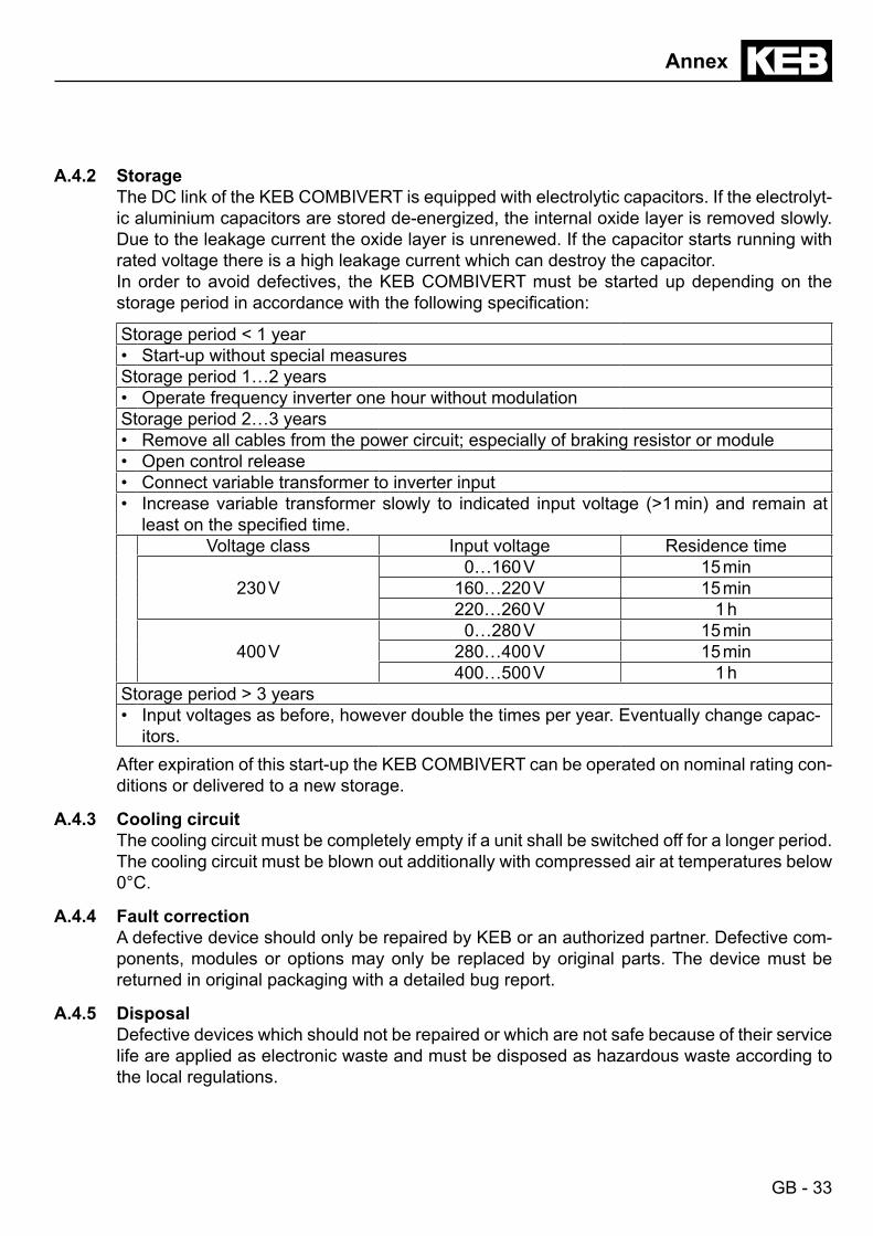
A.4.2 StorageThe DC link of the KEB COMBIVERT is equipped with electrolytic capacitors. If the electrolyt-ic aluminium capacitors are stored de-energized, the internal oxide layer is removed slowly. Due to the leakage current the oxide layer is unrenewed. If the capacitor starts running with rated voltage there is a high leakage current which can destroy the capacitor.In order to avoid defectives, the KEB COMBIVERT must be started up depending on the storageperiodinaccordancewiththefollowingspecification:
Storage period < 1 year• Start-up without special measuresStorage period 1…2 years• Operate frequency inverter one hour without modulationStorage period 2…3 years• Remove all cables from the power circuit; especially of braking resistor or module• Open control release• Connect variable transformer to inverter input• Increase variable transformer slowly to indicated input voltage (>1 min) and remain at
leastonthespecifiedtime.Voltage class Input voltage Residence time
230 V0…160 V 15 min
160…220 V 15 min220…260 V 1 h
400 V0…280 V 15 min
280…400 V 15 min400…500 V 1 h
Storage period > 3 years• Input voltages as before, however double the times per year. Eventually change capac-
itors.After expiration of this start-up the KEB COMBIVERT can be operated on nominal rating con-ditions or delivered to a new storage.
A.4.3 Cooling circuitThe cooling circuit must be completely empty if a unit shall be switched off for a longer period. The cooling circuit must be blown out additionally with compressed air at temperatures below 0°C.
A.4.4 Fault correctionA defective device should only be repaired by KEB or an authorized partner. Defective com-ponents, modules or options may only be replaced by original parts. The device must be returned in original packaging with a detailed bug report.
A.4.5 DisposalDefective devices which should not be repaired or which are not safe because of their service life are applied as electronic waste and must be disposed as hazardous waste according to the local regulations.

GB - 34
Annex
Annex BB.1 Certification
B.1.1 CE MarkingCE marked frequency inverter and servo drives were developed and manufactured to comply with the regulations of the Low-Voltage Directive 2006/95/EC.The inverter or servo drive must not be started until it is determined that the installation com-plies with the Machine directive (2006/42/EC) as well as the EMC-directive (2004/108/EC)(note EN 60204).The frequency inverters and servo drives meet the requirements of the Low-Voltage Directive 2006/95/EC. They are subject to the harmonized standards of the series EN 61800-5-1.This is a product of limited availability in accordance with IEC 61800-3. This product may cause radio interference in residential areas. In this case the operator may need to take cor-responding measures.
B.1.2 UL Marking
Acceptance according to UL is marked at KEB inverters with the adjacent logo on the type plate.
To be conform according to UL for use on the North American and Canadian Market the fol-lowing additionally instructions must be observed (original text of the UL-File):• For control cabinet mounting as „Open Type“• „Only for use in WYE 480V/277V supply sources“• F5: Encoder and Control Board Rating (max. 30 Vdc.: 1 A)• Maximum Surrounding Air Temperature 45 °C (113 °F)• Overload protection at 130 % of inverter output rated current (see type plate)• Motor Overtemperature Protection for Cat. Nos. xxF5CxG-xxxx
Above drive models are not provided with load and speed sensitive overload protection and thermal memory retention up on shutdown or loss of power (for details see NEC, ar-ticle 430.126(A)(2)”.
• „Use 60/75°C Copper Conductors Only“• Terminals - Torque Value for Field Wiring Terminals, the value to be according to the R/C
or Unlisted Terminal Block used.• Use in a Pollution Degree 2 environment• ”Integral solid state short circuit protection does not provide branch circuit protection.
Branch circuit protection must be provided in accordance with the Manufacturer Instruc-tions, National Electrical Code and any additional local codes”, or the equivalent”.
Short Circuit rating and Branch Circuit Protection F5 and F6 G - housing:
Following markings shall be provided:
GB - 35
Annex
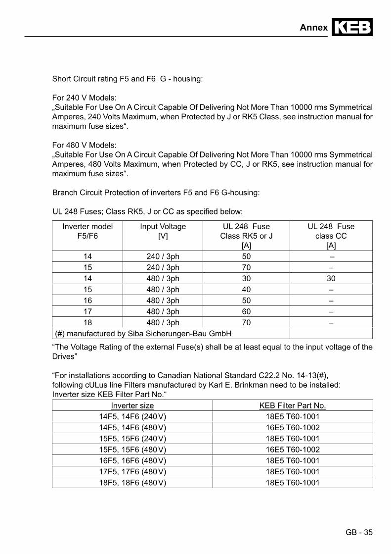
Short Circuit rating F5 and F6 G - housing:
For 240 V Models:„Suitable For Use On A Circuit Capable Of Delivering Not More Than 10000 rms Symmetrical Amperes, 240 Volts Maximum, when Protected by J or RK5 Class, see instruction manual for maximum fuse sizes“.
For 480 V Models:„Suitable For Use On A Circuit Capable Of Delivering Not More Than 10000 rms Symmetrical Amperes, 480 Volts Maximum, when Protected by CC, J or RK5, see instruction manual for maximum fuse sizes“.
Branch Circuit Protection of inverters F5 and F6 G-housing:
UL248Fuses;ClassRK5,JorCCasspecifiedbelow:
Inverter modelF5/F6
Input Voltage[V]
UL 248 Fuse Class RK5 or J
[A]
UL 248 Fuse class CC
[A]14 240 / 3ph 50 –15 240 / 3ph 70 –14 480 / 3ph 30 3015 480 / 3ph 40 –16 480 / 3ph 50 –17 480 / 3ph 60 –18 480 / 3ph 70 –
(#) manufactured by Siba Sicherungen-Bau GmbH
“The Voltage Rating of the external Fuse(s) shall be at least equal to the input voltage of the Drives”
“For installations according to Canadian National Standard C22.2 No. 14-13(#), following cULus line Filters manufactured by Karl E. Brinkman need to be installed:Inverter size KEB Filter Part No.“
Inverter size KEB Filter Part No.14F5, 14F6 (240 V) 18E5 T60-100114F5, 14F6 (480 V) 16E5 T60-100215F5, 15F6 (240 V) 18E5 T60-100115F5, 15F6 (480 V) 16E5 T60-100216F5, 16F6 (480 V) 18E5 T60-100117F5, 17F6 (480 V) 18E5 T60-100118F5, 18F6 (480 V) 18E5 T60-1001
GB - 36
Annex
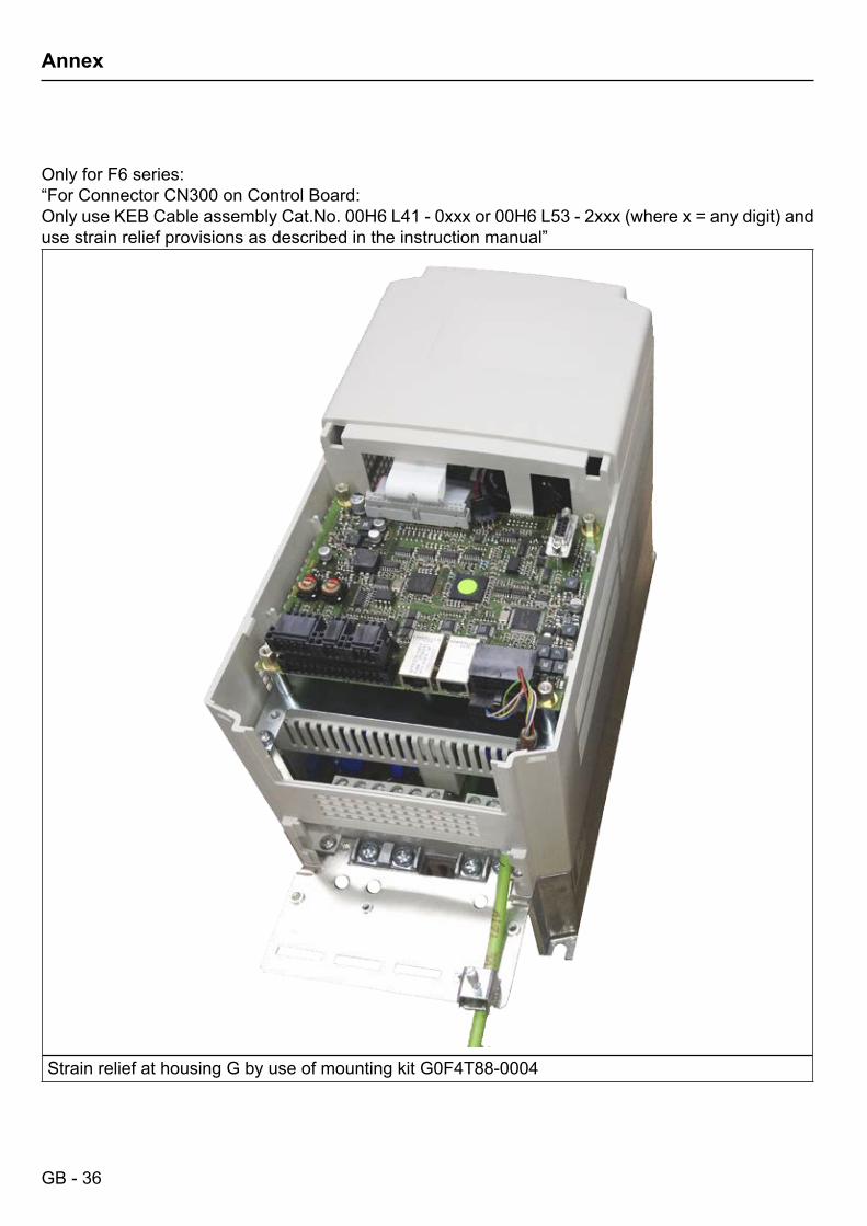
Only for F6 series:“For Connector CN300 on Control Board:Only use KEB Cable assembly Cat.No. 00H6 L41 - 0xxx or 00H6 L53 - 2xxx (where x = any digit) and use strain relief provisions as described in the instruction manual”
Strain relief at housing G by use of mounting kit G0F4T88-0004

GB - 37
Annex
Annex CC.1 Installation of water-cooled units
In continuous operation water-cooled inverters are operated with lower temperature than air-cooled inverters. This has positive effects on lifetime-relevant components such as fan and DC link circuit capacitors and power modules (IGBT). Also the temperature dependent switching losses are positively effected. The use of water-cooled KEB COMBIVERT frequen-cy inverters is offered in the drive technology, because there are process-caused coolants available with some applications. The following instructions must be observed absolutely when this units are used.
C.1.1 Heat sink and operating pressureDesign system Material (voltage) Max. operating pres-
sureConnecting duct
2-plate heat sink Aluminium (-1.67 V) 6 bar 0000650-G140
The heat sinks are sealed with sealing rings and posses a surface protection (anodized) even in the ducts.
In order to avoid a deformation of the heat sink and the damages involved, the indicated max. operating pressure may not be exceeded briefly also by pressure peaks.Pay attention to the guidelines 97/23/EG of pressure units.
C.1.2 Materials in the cooling cicuitFor the screw connections and also for the metallic articles in the cooling circuit which are in contact with the coolant (electrolyte) a material is to be selected, which forms a small voltage difference to the heat sink in order to avoid contact corrosion and/or pitting corrosion (elec-tro-chemical voltage series, see table 1.5.2). An aluminum screw connection or ZnNi coated steel screw connection is recommended. Other materials must be examined in each case beforeemployment.Thespecificcaseofapplicationmustbecheckedby thecustomer intuningofthecompletecoolingcircuitandmustbeclassifiedaccordingtotheusedmaterials.With hoses and seals take care that halogen-free materials are used.A liability for occuring damages by wrongly used materials and from this resulting corrosion cannot be taken over!Table 1.5.2 Electro-chemical voltage series / standard potentials against hydrogenMaterial generated Ion Standard po-
tentialMaterial generated Ion Standard po-
tentialLithium Li+ -3.04 V Cobald Co2+ -0.28 VPotassium K+ -2.93 V Nickel Ni2+ -0.25 VCalcium Ca2+ -2.87 V Tin Sn2+ -0.14 VSodium Na+ -2.71 V Lead Pb3+ -0.13 VMagnesium Mg2+ -2.38 V Iron Fe3+ -0.037 VTitan Ti2+ -1.75 V Hydrogen 2H+ 0.00 VAluminium Al3+ -1.67 V Copper Cu2+ 0.34 V

GB - 38
Annex
Table 1.5.2 Electro-chemical voltage series / standard potentials against hydrogenMaterial generated Ion Standard po-
tentialMaterial generated Ion Standard po-
tentialManganese Mn2+ -1.05 V Carbon C2+ 0.74 VZinc Zn2+ -0.76 V Silver Ag+ 0.80 VChrome Cr3+ -0.71 V Platinum Pt2+ 1.20 VIron Fe2+ -0.44 V Gold Au3+ 1.42 VCadmium Cd2+ -0.40 V Gold Au+ 1.69 V
C.1.3 Requirements on the coolantThe requirements on the coolant are depending on the ambient conditions, as well as from the used cooling system. General requirements on the coolant:Standards TrinkwV 2001, DIN EN 12502 part 1-5, DIN 50930 part 6, DVGW work
sheet W216VGBCooling water direc-tive
The VGB cooling water directive (VGB-R 455 P) contains instructions about common process technology of the cooling. Particulary the in-teractions between cooling water and components of the cooling sys-tem are described.
pH-value Aluminum is particularly corroded by lixiviums and salts. The optimal pH value for aluminum should be in the range of 7.5… 8.0.
Abrasive substanc-es
Abrasive substances as used in abrasive (quartz sand), clogging the cooling circuit.
Copper cuttings Copper cuttings can attach the aluminum and this leads to a galvanic corrosion. Copper should not be used together with aluminum due to electro-chemical voltage difference.
Hard water Cooling water may not cause scale deposits or loose excretions. It shall have a low total hardness (<20°d) especially carbon hardness.
Soft water Soft water (<7°dH) corrodes the material. Frost protection An appropriate antifreeze must be used for applications when the
heat sink or the coolant is exposed temperatures below zero. Use only products of one manufacturer for a better compatibility with other additives.
Corrosion protec-tion
Additives can be used as corrosion protection. In connection with frost protection the antifreeze must have a concentration of 20…25 Vol %, in order to avoid a change of the additives.
Special requirements for open and half-open cooling systems:

GB - 39
Annex
Impurities Mechanical impurities in half-open cooling systems can be counter-acted when appropriate water filters are used.
Salt concentration The salt content can increase through evaporation at half-open sys-tems. Thus the water is more corrosive. Adding of fresh water and removing of process water works against.
Algae and myxo-bacteria
Algae and myxobacteria can arise caused by increased water tem-perature and contact with atmospheric oxygen. The algae and myxo-bacteria clog the filters and obstruct the water-flow. Biocide containing additives can avoid this. Especially at longer OFF periods of the cool-ing circuit preventive maintenance is necessary.
Organic materials The contamination with organic materials must be kept as small as possible, because separate slime can be caused by this
Damages at the unit which are caused by clogged, corroded heat sinks or other ob-vious operating errors, leads to the loss of the warranty claims.
C.1.4 Connection to the cooling system• Screw in connecting duct in accordance with the manual.• The connection to the coolant must be carried out with flexible, pressure-resistant hoses
and secured with clamps.• Pay attention to flux direction and check tightness !• The cooling flow must always be started before starting the KEB COMBIVERT.
The connection to the cooling system can occur as closed or open cooling circuit. The con-nection to a closed cycle cooling circuit is recommended, because the danger of contamina-tion of coolant is very small. Preferably also a monitoring of the pH value of the coolant should be installed.Pay attention to a corresponding cable cross section at required equipotential bonding in order to avoid electro-chemical procedures.
C.1.5 Coolant temperature and moisture condensationThe inlet temperature may not exceed 40 °C. The maximum heat sink temperature is 90 °C depending on the power unit and overload capacity (see „Technical data“). To ensure a safe operation the coolant output temperature must be 10 K below this temperature. Due to high air humidity and high temperatures it can lead to moisture condensation. Moisture condensation is dangerous for the inverter, because the inverter can be destroyed through eventual occuring short-circuits.
The user must guarantee that any moisture condensation is avoided!
In order to avoid a moisture condensation the following possibilities can be done. The appli-cation of both methods is recommended.

GB - 40
Annex
Supply of temper coolantThis is possible by using heatings in the cooling circuit for the control of the coolant temper-ature. The following dew point table is available for this:Coolant inlet temperature [°C] is depending on ambient temperature and air humidity
Air humidity [%]
Surroundingtemperature [°C]
10 20 30 40 50 60 70 80 90 100
-25 -45 -40 -36 -34 -32 -30 -29 -27 -26 -25-20 -42 -36 -32 -29 -27 -25 -24 -22 -21 -20-15 -37 -31 -27 -24 -22 -20 -18 -16 -15 -15-10 -34 -26 -22 -19 -17 -15 -13 -11 -11 -10-5 -29 -22 -18 -15 -13 -11 -8 -7 -6 -50 -26 -19 -14 -11 -8 -6 -4 -3 -2 05 -23 -15 -11 -7 -5 -2 0 2 3 510 -19 -11 -7 -3 0 1 4 6 8 915 -18 -7 -3 1 4 7 9 11 13 1520 -12 -4 1 5 9 12 14 16 18 2025 -8 0 5 10 13 16 19 21 23 2530 -6 3 10 14 18 21 24 26 28 3035 -2 8 14 18 22 25 28 31 33 3540 1 11 18 22 27 31 33 36 38 4045 4 15 22 27 32 36 38 41 43 4550 8 19 28 32 36 40 43 45 48 50
Temperature ControlThe cooling system can be connected by means of pneumatic or magnetic valves. A relay is frontend. In order to avoid pressure surges, the valves for the temperature control must be inserted before the cooling circuit. All usual valves can be used. Pay attention that the valves are faultless and do not clamp.

GB - 41
Annex
C.1.6 Coolantheatingdependingonpowerlossandflowratewithwater
0
1
2
3
4
5
0 1 2 3 4 5 6 7 8 9 10 11 12 13 14 15Pv [kW]
ΔT [K]
100 l/min
50 l/min
40 l/min30 l/min20 l/min10 l/min5 l/min
C.1.7 Typicallyfallofpressuredependingontherateofflow
bar
0.00.10.20.30.40.50.60.70.80.91.01.11.21.31.41.51.61.7
0 5 10 15 20 25 30 35 40 45 50l/min

GB - 42
Annex
Annex DD.1 Changing the response threshold of the braking transistor
(not valid for control type „BASIC“)
To avoid a premature switching of the brake transistor at an input rated voltage of 480 Vac, the response threshold must be controlled or adjusted according to the following graphic.
STOP
ENTERF/R
ENTERF/R
FUNC.SPEED
FUNC.SPEED
START
START
FUNC.SPEED
FUNC.SPEED
FUNC.SPEED
FUNC.SPEED
ENTERF/R
START
START
START
ENTERF/R
ENTERF/R

GB - 43
Notes

KEB Antriebstechnik Austria GmbHRitzstraße8•A-4614Marchtrenk
fon:+43724353586-0•fax:+43724353586-21net: www.keb.at•mail:[email protected]
KEB AntriebstechnikHerenveld2•B-9500Geraadsbergen
fon:+3254437860•fax:+3254437898mail: [email protected]
KEB Power Transmission Technology (Shanghai) Co.,Ltd.No. 435 Qianpu Road, Chedun Town, Songjiang District,
CHN-Shanghai 201611, P.R. Chinafon:+862137746688•fax:+862137746600
net: www.keb.de•mail:[email protected]
KEB Antriebstechnik Austria GmbHOrganizačnísložka
Suchovrbenskenam.2724/4•CZ-37006ČeskéBudějovicefon:+420387699111•fax:+420387699119
mail: [email protected]
KEB Antriebstechnik GmbHWildbacherStr.5•D–08289Schneebergfon:+49377267-0•fax:+49377267-281
mail: [email protected]
KEB EspañaC/ Mitjer, Nave 8 - Pol. Ind. LA MASIA
E-08798 Sant Cugat Sesgarrigues (Barcelona)fon:+34938970268•fax:+34938992035
mail: [email protected]
Société Française KEBZ.I.delaCroixSt.Nicolas•14,rueGustaveEiffel
F-94510 LA QUEUE EN BRIEfon:+33149620101•fax:+33145767495
net: www.keb.fr•mail:[email protected]
KEB (UK) Ltd.Morris Close, Park Farm Industrial Estate
GB-Wellingborough, NN8 6 XFfon:+441933402220•fax:+441933400724
net: www.keb.co.uk•mail:[email protected]
KEB Italia S.r.l.ViaNewton,2•I-20019SettimoMilanese(Milano)
fon:+39023353531•fax:+390233500790net: www.keb.de•mail:[email protected]
KEB Japan Ltd.15–16, 2–Chome, Takanawa Minato-ku
J-Tokyo 108-0074fon:+8133445-8515•fax:+8133445-8215
mail: [email protected]
KEB Korea SeoulRoom 1709, 415 Missy 2000
725 Su Seo Dong, Gang Nam GuROK-135-757 Seoul/South Korea
fon:+82262536771•fax:+82262536770mail: [email protected]
KEB RUS Ltd.Lesnaya Str. House 30, Dzerzhinsky (MO)
RUS-140091 Moscow regionfon:+74956320217•fax:+74956320217
net: www.keb.ru•mail:[email protected]
KEB America, Inc.5100 Valley Industrial Blvd. South
USA-Shakopee, MN 55379fon:+1952224-1400•fax:+1952224-1499
net: www.kebamerica.com•mail:[email protected]
© KEBMat.No. 00F50EB-KG00
Rev. 1CDate 10/2016
More and latest addresses at http://www.keb.de
KEB Automation KGSüdstraße 38•D-32683Barntrup
fon:+495263401-0•fax:+495263401-116net: www.keb.de•mail:[email protected]
KEB worldwide…