Embed Size (px)
Citation preview
i
COMBINING SEISMIC AND GEOTECHNICAL METHODS TO IMPROVE THE
PREDICTION OF PHYSICAL SOIL PROPERTIES
BADEE ALSHAMERI
A thesis submitted in
fulfilment of the requirement for the award of the
Doctor of Philosophy
Faculty of Civil and Environmental Engineering
Universiti Tun Hussein Onn Malaysia
JUNE 2017

iii
For my beloved wife Nawal, my sons Elyas and Muhammad, my mother and father,
my sisters and brother, and my sister in law

iv
ACKNOWLEDGEMENT
I would like to express my sincere appreciation to my supervisor, Professor Emeritus
Dato’ Dr. Ismail Bakar, co-supervisor Associate Professor Dr. Aziman Madun,
Ministry of High Education Yemen, and Ministry of Higher Education of Malaysia for
the support that given throughout the duration of my Ph.D. study

v
ABSTRACT
Seismic investigation offers subsurface information in a cost and time effective way
compared with the geotechnical methods. The seismic data (i.e. bender element data)
needs to be correlated with geotechnical data allowing it to be adopted in engineering
designs. However, the procedures and analysis of bender element (BE) data can be
subjected to crucial errors due to several limitations in the BE tools such as the
magnitude of seismic source and frequency range. In addition, little attention had been
paid to adopt field BE despite the other field seismic methods having low resolution
when assessing the properties of the thin targeting layers of soil as pavement layers.
Therefore, this research aim was to evaluate the limitations and reliability of BE
procedure in the laboratory and the field. The research had two main stages; laboratory
and model stages. In the laboratory stage, the BE limitations were assessed using
homogeneous and unchanged properties of polystyrene sample instead of soil. In
addition, various mixtures of sand-kaolin were investigated using the shear box,
compaction and BE to obtain its empirical correlation as well as the obtained result
was used to construct the soil model. In the model stage, the multi-thin layers model
consisting of sand-kaolin mixtures was constructed for the purpose of suggesting the
field BE procedure. The laboratory BE results recommended that the two sensors
relative rotation shall be less than 50o, the position of two sensors alignment ratio
between the horizontal and vertical distance shall be less than 0.5, and the effect of
sample boundary occured when the ratio between the distance to sample boundary and
the sample thickness less than 0.38. In model stage; the recommended procedure to be
adopted in the field was via placing the BE sensors spacing less than 1 m and the BE
crosshole method via placing the sensors at both side of the targeted layer was the best
option. However, this method required some of the testing preparation. In conclusion,
the BE limitations and procedures in the laboratory and field had been evaluated and
investigated then recommended the procedures to improve the reliability of the BE
results.

vi
ABSTRAK
Penyiasatan seismik dapat memberikan maklumat subpermukaan dengan kos dan
masa yang efektif berbanding menggunakan kaedah geoteknikal yang konvensional.
Data seismik diperolehi dengan kaedah unsur bender perlu dikaitkan dengan data
geoteknik bagi membolehkan data ini diguna pakai dalam reka bentuk kejuruteraan.
Walaubagaimanapun, prosedur dan analisa data unsur bender (BE) terdedah kepada
kesalahan disebabkan oleh beberapa limitasi peralatan BE seperti magnitud sumber
seismik dan julat frequensi. Tambahan pula hanya sedikit sahaja perhatian yang
diberikan berkaitan denganpenggunaan BE di lapangan walaupun telah diketahui
bahawa kaedah seismik konvensional menghadapi masalah resolusi yang rendah bagi
menilai lapisan tanah yang nipis seperti lapisan turapan. Oleh yang demikian,
matlamat kajian ini adalah untuk menilai limitasi dan kebolehpercayaan kaedah BE di
makmal dan di lapangan. Kajian dibahagi kepada dua peringkat utama iaitu di makmal
dan model. Di peringkat makmal, limitasi BE dinilai dengan menggunakan
polystyrene yang homogen dan tidak berubah sifat berbanding dengan menggunakan
tanah. Di samping itu, pelbagai campuran antara pasir dan kaolin dikaji menggunakan
ujian ricih, pemadatan dan BE bagi mendapatkan korelasi empirikal dan menggunakan
keputusan tersebut bagi membina model untuk kajian seterusnya. Di peingkat model,
pelbagai lapisan tanah nipis yang terdiri dari campuran pasir dan kaolin dibina bagi
tujuan mendapatkan prosedur BE di lapangan. Di makmal, keputusan BE
mencadangkan kedudukan putaran relatif dua sensor mestilah kurang 50°, dan
kedudukan nisbah jajaran dua sensor antara jarak mendatar dan menegak mestilah
kurang 0.5, dan kesan sempadan sampel terjadi apabila nisbah jarak antara sempadan
sampel dan ketebalan sampel kurang dari 0.38. Pada peringkat model,
mencadangankan prosedur di lapangan adalah dengan meletakkan jarak sensor BE
kurang dari 1 m dan menggunakan kaedah lubang silang BE dengan meletakkan sensor
di kedua hujung lapisan yang dikaji. Walaubagaimanapun kaedah ini memerlukan
persiapan lapangan yang lebih. Kesimpulannya, limitasi dan kaedah BE di makmal
dan lapangan telah berjaya dinilai, dikaji dan prosedur untuk membaiki
kebolehpercayaan keputusan BE telah dicadangkan.
vii
CONTENTS
ACKNOWLEDGEMENT iv
ABSTRACT v
ABSTRAK vi
CONTENTS vii
LIST OF TABLES ix
LIST OF FIGURES xi
LIST OF SYMBOLS AND ABBREVIATIONS xviii
CHAPTER 1 INTRODUCTION 1
1.1 Background of the Study 1
1.2 Problem Statement 3
1.3 Aim and Objectives 4
1.4 Originality of the Outcomes 4
1.5 Research Scope and Limitations 5
1.6 Outline of Thesis 6
CHAPTER 2 SEISMIC AND GEOTECHNICAL INVESTIGATION 7
2.1 Seismic Exploration 7
2.2 Seismic Methods 20
2.3 Bender Element 27
2.4 Importance of the Correlation between the Seismic and
Geotechnical Data
48
2.5 Brief Comparison between Bender Element and Other
Methods
50
2.6 Bender Element Applications 51
2.7 Field Bender Element 57
2.8 Geotechnical Methods 57

viii
2.9 Seismic and Geotechnical Tests Correlations 64
2.10 Summary 74
CHAPTER 3 EQUIPMENT SETUP AND PROCEDURES 77
3.1 Introduction 77
3.2 Laboratory Stages 79
3.3 Physical Model (Simulated Field) Stages 104
CHAPTER 4 BENDER ELEMENT ASSESSMENTS 119
4.1 Effect of Sensor Rotation 120
4.2 Effect of Sensor Alignment 126
4.3 Effect of Boundary Condition and Near-Field Effect 132
CHAPTER 5 GEOTECHNICAL LABORATORY RESULTS 149
5.1 Effect of Fine Content and Density towards the Shear
Strength Parameters
150
5.2 Effect of Fine Content and Moisture Content towards the
Shear Strength Parameters
160
CHAPTER 6 BENDER ELEMENT APPLICATIONS 174
6.1 Correlations of the Seismic and Geotechnical Data in the
Laboratory
174
6.2 Simulated Field Testing of the Bender Element 196
CHAPTER 7 CONCLUSION AND RECOMMENDATIONS 207
7.1 Introduction 207
7.2 Outcomes of Objectives 208
7.3 Recommendations for Improving the Bender Element
Efficiency
212
7.4 Future Work 213
REFERENCES 214
APPENDICES 242

ix
LIST OF TABLES
2.1 Typical shear wave velocity for some common materials 16
2.2 Brief comparison between analysis methods for seismic signals 34
2.3 The recommended Ltt/λ from previous researchers 37
2.4 Seismic wave velocity and maximum modulus versus some
geotechnical properties
49
2.5 Comparative analyses of shear wave methods 66
2.6 Empirical correlation between seismic data from different
methods and geotechnical parameters from previous researchers
74
3.1 Dimension, densities, and unit weight of polystyrene samples 81
3.2 Correlative points and their corresponding frequency range 84
3.3 Number of samples used for each test 94
3.4 Sand-kaolin mixtures 94
3.5 Thickness of the soil mixtures samples 103
3.6 Acquisition setup 116
4.1 Results of wave velocities range of the five methods 128
5.1 Results of soil mixtures compaction 151
5.2 Results of direct shear test for different soil mixtures at MDD 152
5.3 Comparison of the location of highest and lowest values of shear
strength parameters
158
5.4 Specific gravity for sand-kaolin mixtures 161
5.5 Results of direct shear test for different soil mixtures 162
6.1 Properties of the soil mixtures 176
6.2 Soil strength parameters for the four mixtures 176
6.3 Empirical correlation equations between FC and SC toward the
seismic data
178

x
6.4 Empirical correlation equations between void ratio and the
seismic data
180
6.5 Empirical correlation equations between intergranular void ratio
and the seismic data
181
6.6 Empirical correlation equations between optimum moisture
content and the seismic data
184
6.7 Empirical correlation equations between densities and the
seismic data
187
6.8 Empirical correlation equations between Gs and the seismic data 189
6.9 Empirical correlation equations between friction angle and
cohesion toward the seismic data
191
6.10 Empirical correlation equations between shear strength and the
seismic data
194
6.11 The specification of layers inside the tank 197

xi
LIST OF FIGURES
2.1 Seismic exploration sequence 8
2.2 Strain (∆h/h) is proportional to stress (F/A) (Lowrie, 2007) 8
2.3 Shear modulus (Lillie, 1999) 9
2.4 Young’s modulus (Lillie, 1999) 10
2.5 Propagation of seismic wave (Lowrie, 2007) 11
2.6 P-wave propagation method (Lillie, 1999) 12
2.7 Elastic deformations and ground particle motions associated
with the passage of primary wave P-wave (Kearey et al., 2002)
12
2.8 S-wave propagation method (Lillie, 1999) 13
2.9 Elastic deformations and ground particle motions associated
with the passage of shear wave S-wave (Kearey et al., 2002)
13
2.10 Particle motions due to different types of seismic waves (Lillie,
1999)
14
2.11 Body and surface seismic waves movement and velocities
(Milsom & Eriksen, 2011)
15
2.12 Primary wave velocity versus ripabilities in common rocks
(Milsom & Eriksen, 2011)
16
2.13 Wavefront and ray path (Reynolds, 2011; Kearey et al., 2002) 19
2.14 Seismic methods 21
2.15 Reflected and refracted wave in Snell’s law 22
2.16 Spectral analysis of surface waves method (SASW) 24
2.17 Continuous surface waves seismic method (CSW) 24
2.18 Refraction Microtremor Method (ReMi) 24
2.19 Multi-channel analysis of surface waves (MASW) 25
2.20 Seismic borehole methods 25

xii
2.21 Flowchart of bender element issues 27
2.22 Bender element polarisation and configurations types 29
2.23 Flagging movement in the y-poled polarisation bender element 30
2.24 The punching movement in x-poled polarisation at bender
element
30
2.25 Different positions to calculate the arrival time 33
2.26 Precautions during implementation of bender element test 35
2.27 Illustration of SH and SV propagation 36
2.28 Boundary conditions issue in the bender element 39
2.29 Overshooting obscured the correct arrival time at line A-A
(Jovicic et al., 1996)
41
2.30 Crosstalk effect (Lee & Santamarina, 2005) 43
2.31 Effect of moisture content on VS (Indraratna et al., 2012) 46
2.32 Effect of FC on arrival time of VS (Yang & Liu, 2016) 46
2.33 Modulus from seismic and geotechnical tests 51
2.34 Integrate BE with Oedometer (Zeng & Ni, 1999) 52
2.35 Integrate BE with triaxial (Pennington et al., 1997) 52
2.36 Bender bimorph install at triaxial chamber (De Alba et al., 1984) 53
2.37 Comparison of VS with void ratio (De Alba et al., 1984) 53
2.38 Tomographic hardware–transducer installation within readily
replaceable anchors, and supporting frame (Lee et al., 2005)
54
2.39 The bender element attached to unconfined axial compression
test device (Lee et al., 2014)
55
2.40 E and fc versus VP (Lee et al., 2014) 56
2.41 Understanding the components of the empirical correlation
equations
58
2.42 VS profiles from MASW and CHS (Lopes et al., 2014) 66
2.43 N value versus VS from SPT and MASW (Lopes et al., 2014) 70
2.44 Variation of VS and SPT-N with depth (Maheswari et al., 2010) 71
2.45 Void ratio from VP and VS versus laboratory e (Jamiolkowski,
2012)
72
2.46 Void ratio from VP and VS versus laboratory e (Jamiolkowski,
2012)
73

xiii
3.1 Research experiments layout 78
3.2 Laboratory stages 79
3.3 Bender element limitations and procedures assessments 79
3.4 Example for polystyrene sample 81
3.5 The soil sample was damaged during the reshaping process 81
3.6 Picking arrival time from GDS software 82
3.7 Comparison between the pick methods and data type 83
3.8 Screen captured for CCexcel method’s configurations 85
3.9 Bender element analysis tools (BEAT) 87
3.10 Position sketch of transmitter and receiver in polystyrene
sample
89
3.11 The position of BE sensors (not true scale) 90
3.12 Sketch for the sample dimension using fixed wave path and
different Dr/Ltt
91
3.13 Implementation of the laboratory geotechnical tests 93
3.14 Preparing the soil mixtures 94
3.15 Conducting the standard compaction test 99
3.16 Determination of MDD and OMC (using FC = 70%) 99
3.17 Shearing the sand-kaolin sample inside the direct shear box 101
3.18 Flow chart of laboratory bender element test 102
3.19 Soil sample mixture which was subjected to laboratory bender
element test
103
3.20 Flow chart showing the field stage 104
3.21 Hidden and blind layers (Kearey et al., 2002) 105
3.22 Flow chart of designing the physical model 105
3.23 Triangle sketch as a function of wave path 106
3.24 Simulation of the seismic wave path 107
3.25 Simulation results 108
3.26 Preparing the physical model 109
3.27 Model Layout 109
3.28 Outside model trail test 110
3.29 Parallel arrangement for bender element sensors at the top of the
layer
110

xiv
3.30 Support the tank 111
3.31 Setup the framework with side support inside the tank 111
3.32 Setup the jumper rammer inside the framework and performed
the compaction
112
3.33 SUBARU compactor rammer model 4.0 Robin EH12 112
3.34 Field seismic test 113
3.35 Layout and seismic wave path in for the SR and MASW survey 114
3.36 Offset arrangements 115
3.37 Bender element test in different sensors arrangements 116
3.38 Bender element tests; (a) fixed side spacing for all layers, (b)
increment spacing of the top layer, (c) individual spacing of the
top layer, and (d) CH and CHm
117
3.39 Bender element test; (a) SS, (b) DH, and (c) CH at different
spacing
117
4.1 Graphical concept of bender element limitations investigation 119
4.2 Wave velocity versus sensor rotation 121
4.3 ACR versus sensor rotation 122
4.4 Graphical summary of the sensor rotation results 123
4.5 ACR of P-wave at different sample thicknesses 124
4.6 ACR of S-wave at different sample thicknesses 125
4.7 VP versus Dh 127
4.8 VS versus Dh 127
4.9 VP versus Dh/D 127
4.10 VS versus Dh/D 128
4.11 ACR versus Dh 129
4.12 ACR versus Dh/D 129
4.13 Graphical summary of sensor alignment results 130
4.14 ACR trend-line versus Dh/D 131
4.15 Wave velocity versus Dr/Ltt 133
4.16 Wave velocity at free and rigid boundary 134
4.17 Comparison of the shear wave signal records at different Dr/Ltt 136
4.18 Comparison of the compression wave signal records at different
Dr/Ltt
137
xv
4.19 VS at free and rigid boundary 137
4.20 Wave velocities at different frequencies for sample 8.71 mm 140
4.21 Wave velocities at different Ltt/λ for sample 8.71 mm 140
4.22 Wave velocities at different frequencies for sample 14.51 mm 140
4.23 Wave velocities at different Ltt/λ for sample 14.51 mm 141
4.24 Wave velocities at different frequencies for sample 29.75 mm 141
4.25 Wave velocities at different Ltt/λ for sample 29.75 mm 141
4.26 Wave velocities at different frequencies for sample 62.9 mm 142
4.27 Wave velocities at different Ltt/λ for sample 62.9 mm 142
4.28 Wave velocities at different frequencies for sample 87.71 mm 142
4.29 Wave velocities at different Ltt/λ for sample 87.71 mm 143
4.30 Wave velocities at different frequencies for sample 200.48 mm 143
4.31 Wave velocities at different Ltt/λ for sample 200.48 mm 143
4.32 Wave velocities at different samples thicknesses and methods 144
4.33 Graphical conclusion of boundary and near-field effect results 147
5.1 Graphical conclusion of geotechnical tests results 149
5.2 The particle size distribution of sand at the different FC 150
5.3 Compaction curves 151
5.4 Cohesion versus density 153
5.5 Friction angle versus density 153
5.6 Shear strength versus wet density 154
5.7 Shear strength versus maximum dry density 154
5.8 Shear modulus versus wet density 154
5.9 Shear modulus versus maximum dry density 155
5.10 Cohesion versus fine content 156
5.11 Friction angle versus fine content 156
5.12 Shear strength versus fine content 156
5.13 Shear modulus versus fine content 157
5.14 Cohesion versus moisture content at different fine content (FC) 163
5.15 Friction angle versus moisture content at different fine content
(FC)
164
5.16 Shear modulus versus moisture content at different fine content
(FC)
166

xvi
5.17 Shear strength versus moisture content at different fine content
(FC)
167
5.18 Cohesion versus fine content at different moisture content (w) 169
5.19 Friction angle versus fine content at different moisture content
(w)
170
5.20 Shear strength versus fine content at different moisture content
(w)
172
6.1 Graphical illustration of correlating the seismic and
geotechnical data
175
6.2 Wave velocity versus fine and sand content 177
6.3 Gmax and Emax versus fine and sand content 177
6.4 Comparison of the effect of FC on wave velocity with previous
works
178
6.5 Comparison of the effect of FC on Gmax with previous works 178
6.6 Seismic data versus void ratio 179
6.7 Comparison of the effect of e on VS with previous works 180
6.8 Comparison of the effect of e on Gmax and Emax with previous
works
181
6.9 Seismic data versus intergranular void ratio 182
6.10 Comparison of the effect of es on VS with previous works 183
6.11 Seismic data versus OMC % 184
6.12 Comparison of the effect of w% on wave velocities with
previous works
185
6.13 Comparison of the effect of w% on Gmax with previous works 185
6.14 Seismic data versus ρwet and MDD 186
6.15 Comparison of the effect of density on wave velocity with
previous works
188
6.16 Seismic data versus specific gravity 189
6.17 Comparison of the effect of Gs on VS with previous works 189
6.18 Wave velocity versus cohesion and friction angle 191
6.19 Maximum modulus versus cohesion and friction angle 191
6.20 Comparison of the effect of friction angle on the wave velocity
with previous works
193

xvii
6.21 Comparison of the effect of cohesion on the wave velocity and
Emax with previous works
193
6.22 Wave velocity and maximum modulus versus shear strength τ 194
6.23 Comparison of the effect of soil strength on VS with previous
works
195
6.24 Verification and assessment of the bender element in the field 196
6.25 Seismic wave velocities from different methods 199
6.26 Seismic wave velocities after delay the test’s procedure 199
6.27 Seismic wave velocities at different sensors arrangements 201
6.28 Effect of the sensors arrangement on outputs seismic wave types 201
6.29 Seismic wave velocity at different Ltt 202
6.30 Crosshole (CH), and multi-layer crosshole measurement (CHm) 204
6.31 Crosshole (CH), suspension (SS), and downhole measurement
(DH)
204
6.32 Direct and refracted seismic wave velocity at middle and base
layers
205

xviii
LIST OF SYMBOLS AND ABBREVIATIONS
∆F - Applying shear force (i.e. tangential force)
∆h - Changing in rod high (i.e. length)
∆l - Displacement
∆Lr - Changing in the rod length
∆W - Amount of decrease the width
A - Cross sectional area
a - Soil constant
ACR - Amplitude comparison ratio
Ar - Amplitude of receiver in millivolt
As - Amplitude of transmitter in volte
BE - Bender element
BEAT - Bender element analysis tools
BHS - Seismic borehole
c - Cohesion
CCexcel - Cross-correlation using excel
CCGDS - Cross-correlation methods using beat
CC-normexcel - Normalized correlation coefficient
CCxy (ts) - Time for maximum value of cross-correlation
CH - Crosshole method
CHm - Multi-layer crosshole
CHS - Seismic crosshole method
CL - Clay content
CPT - Cone penetration test
CPTu - Piezocone penetration tests
CSW - Continuous surface wave

xix
D - Sample thickness
d1 - Distance between R1 and R2
d2 - Distance between S and R
d50 - Mean particle size at 50% of percent finer
DC - Dynamic compaction
Dh - Horizontal distance to centre axis of the sample
DH - Downhole method
DHS - Seismic downhole method
di - Shear box diameter
dmax - Maximum particle size
Dr - Distance to the boundary
E - Young’s modulus
e - Void ratio
e0 - In-situ void ratio
E0 - Initial Young’s modulus
egk - Gravel skeleton void ratio
Emax - Maximum Young’s modulus
es - Intergranular void ratio
esk - Sand skeleton void ratio
f - Frequency f
F - Applied force F
fc - Compressive strength
FC - Fine content FC
G - Shear modulus (i.e. modulus of the shear rigidity)
G0 - Initial shear modulus
GC - Gravel content
GDS - Global digital systems
Gmax - Maximum shear modulus
Gs - Specific gravity
Gsf - Specific gravity for fine material
h - Height (i.e. Length) of the rod
Hs - Sample high in direct shear test
l - Length of cube of material

xx
L - Wave path length
lb - Intruded length of the sensor
Lr - Original length of rod
Ltt - Wave path length from tip of transmitter to tip of receiver
M1 - Mass of moist container
M2 - Mass of dry container and soil
MASW - Multi-channel analyses of surface waves
MDD - Maximum dry density
Mequal - Mass of equal water
Mmd - Mass of dry compaction mould
Mp1 - Mass of dry pycnometer
Mp2 - Mass of dry pycnometer and mixture
Mp3 - Mass of saturated pycnometer and mixture
Mp4 - Mass of pycnometer and water
Ms - Mass of the solid
MSW - Municipal solid waste
Mt - Mass of moist soil in mould
Mt - Mass of compacted sample and mould
Mw - Mass of water
Mw - Mass of solid material
N - Uncorrected blow account for SPT
n - Elastic constant
OMC - Optimum moisture content
P - Original confining pressure
Pa - Atmospheric pressure
P-wave - Primary (compression) wave
qa - Allowable bearing capacity
qc - Cone tip resistance
qf - Ultimate bearing capacity
qt - Corrected cone tip resistance
R1, R2 - Sensor number 1 and sensor number 2
RC - Resonant column
ReMi - Refraction microtremor

xxi
RS - Receiver signal
SASW - Spectral analysis of surface waves
SC - Sand content
SCPT - Seismic cone penetrometer test
SPT - Standard penetration test
SR - Seismic refraction
SS - Seismic suspension
S-wave - Secondary (shear) wave
t - Travel time
T - Corresponding to the signal time record
t100 - Time at the peak shear stress
t50 - Time at 50 % of the peak shear stress
ts - Time shift for transmitter signal
V1 - Velocity at first layer
V2 - Velocity at second layer
Vc - Volume of coarse content
VE - Extensional wave velocity in narrow bar (equal to Vp)
Vf - Volume of fine content
Vm - Volume of the mould
VP - Compression wave velocity
VP, C-C - Compression wave from first-deflection methods (C-C)
VP, D-D - Compression wave from first-peak methods (D-D)
VP, F-F - Compression wave from first-trough methods (F-F)
VP2 - Compression wave velocity from the second wave cycle
VP2, C-C* - Compression wave from second deflection methods (C-C*)
VP2, D-D* - Compression wave from second pick methods (D-D*)
VP2, F-F* - Compression wave from second trough methods (F-F*)
VPR - Reflected P-wave
VR - Rayleigh wave velocity
VS - Shear wave velocity
VS, C-A, near-field - Shear wave from first-deflection methods inside the near-field
zone (C-C)
VS, C-C - Shear wave from first-deflection methods (C-C)

xxii
VS, D-D - Shear wave from first-peak methods (D-D)
VS, F-F - Shear wave from first-trough methods (F-F)
VS2 - Shear wave velocity from the second wave cycle
VS2, C-C* - Shear wave from second deflection methods (C-C*)
VS2, D-D* - Shear wave from second pick methods (D-D*)
VS2, F-F* - Shear wave from second trough methods (F-F*)
Vv - Volume of voids
W - Original width of rod
w - Moisture content
wsat - Saturation point
X(T) - Corresponds to receiver signal
Xc - Critical distance
Xcr - Crossover distance
Y(T) - Corresponding to transmitter signal
z - Depth
γ - Unit weight
γd - Dry unit weight
γMDD - Unit weight of maximum dry density
γt - Total unit weight
γw - Unit weight of water
ε - Strain
ε100 - Shear strain at the peak shear stress
ε50 - Shear strain at 50 % of the peak shear stress
θc - Critical angle
θi - Incidence angle
θr - Refracted angle
λ - Wavelength
μ - Shear modulus (same as G)
ν - Poisson’s ratio
ρ - Bulk density
ρd - Dry density
ρm - Moist density
ρwet - Wet density

xxiii
σ - Applied normal stress (i.e. confining stress)
σv - Overburden pressure
σ'v - Effective vertical stress
τ - Shear strength
ϕ - Friction angle
ϕ’ - Effective friction angle

1
CHAPTER 1
INTRODUCTION
1.1 Background of the Study
Both geotechnics and seismic methods have numerous approaches to measure soil
properties. These methods are classified as field or laboratory tests (Das & Sobhan,
2014; Reynolds, 2011). Geotechnical testing (e.g. shear box, triaxial test, and
unconfined compression test) provides strength parameters which is used directly in
the engineering design. While seismic methods assess geomaterial characterisations
(e.g. seismic wave velocity) which is used to predict the design’s parameters (e.g.
strength parameters) using empirical correlation equations (Milsom & Eriksen, 2011;
Mayne et al., 2002).
The seismic methods need to be improved to overcome difficulties related to
the data quality. The seismic data is less effective in engineering design compared with
geotechnical data (i.e. direct data) where the design parameters are predicted rather
than measured directly (Martínez et al., 2015; Foti et al., 2014). Seismic data can be
improved by combining the different seismic methods to avoid the weakness of
predicted data and correlating the seismic data to the geotechnical data. The
advantages of seismic investigation compared with the geotechnical methods include;
(a) cost and time efficiency, (b) being a non-destructive test and non-invasive method,
and (c) suitable for investigating areas where it is difficult to use the direct methods

2
due to high cost or contamination, etc. (Shokri et al., 2016; Martinho & Dionísio,
2014).
Seismic methods had seen rapid development in recent decades, and the range
of their usage has broadened. For example, seismic reflection and refraction methods
are being used in deep exploration while the surface wave methods are used in the
shallow investigation. Both seismic reflection and refraction depend on analysing the
body waves while the surface wave methods depend on analysis the surface waves.
The seismic refraction, reflection and surface wave analysis methods are classified as
field methods. While the bender element (BE) and the ultrasonic methods are used in
the laboratory to measure the body seismic wave velocities VP and VS (i.e. primary
and shear seismic wave velocities respectively).
The bender element BE has been commonly used in the laboratory due to its
simplicity, versatility, relative small sensors, the flexibility of using sensors in a
different direction, fast, inexpensive, and non-destructive method (Valle-Molina &
Stokoe, 2012). Despite its many advantages, several factors can nevertheless affect the
BE data leading to pseudo results. These factors include; (a) length of sensors, (b)
sensor alignment, (c) sensor rotation, (d) boundary condition, (e) near-field effect, (f)
signal noise, and (g) signal damping (Moldovan et al., 2016; Karray et al., 2015).
Although some of these parameters had been studied by previous researchers, their
direct application had not been examined. For example, Zeng et al. (2007), Lee &
Santamarina (2005), and Clayton et al. (2004) mentioned the effect of the sensor
alignments and sensor rotation, but they did not provide a clear definition of the
effective zones of these parameters. The near-field effect had been studied, but the
results had recommended different ratios of wave path length to the wavelength (Ltt/λ)
which questions the efficiency of the recommended ratios (Leong et al., 2009; Jovicic
et al., 1996; Viggiani & Atkinson 1995a; Sa´nchez-Salinero et al., 1986).
Although the bender element is used commonly in the laboratory, little
attention had been paid to developing the usage of the bender element in the field. The
field BE method can be useful for examining thin soil layers (e.g. compaction layers
and pavement) where the resolution of other seismic methods was low and subjected
to several limitations rendering its results uncertain (Castellaro et al., 2015; Everett,
2013). Most BE field trials were applied in a single layer while field conditions are
often multi-layer. Moreover, there is no specific definition for the boundary condition

3
effect, nor are there recommended procedures and sensor arrangements (Lee et al.,
2012; Jang et al., 2010; Kim et al., 2009; Zhou et al., 2008).
1.2 Problem Statement
The bender element is a non-destructive test and appears deceptively simple, but
questions were raised about the quality of BE data which is affected by the procedure
of positioning the transmitter and receiver sensors such as the BE sensors rotation and
the BE sensors alignment. The sample dimension was also influenced the wave
propagation via the boundary condition, the near and far field effect, and the seismic
source frequency. To date, the recommended zone of positioning the transmitter and
receiver sensors yet to define in the BE standard procedure and causes inconsistency
in measuring the seismic wave velocity. This research assessed these factors and thus
to improve the efficiency of laboratory bender element tests. In addition, to improve
the quality of predicting the physical soil properties (e.g. soil strength parameters) from
the bender element data (i.e. seismic data), both seismic and geotechnical data must be
correlated. In this research, most of the geotechnical data such as index soil properties
(e.g. fine content, moisture content, void ratio, and specific gravity), compaction
parameters (e.g. maximum dry density and optimum moisture content), and soil
strength parameters (e.g. shear strength, cohesion, friction angle, and elastic modulus)
were correlated to the seismic data (i.e. seismic wave velocities and maximum
modulus).
These laboratory experiments and correlations (i.e. geotechnical and seismic
experiments and correlations) were assisted to build simulated field condition in order
to investigate the reliability and suggested the procedure of the bender element on the
field. Little attention had been given to developing the application of BE in the field
particularly at thin soil layers (e.g. thin compacted layers and pavement). The results
of other seismic methods (e.g. seismic refraction and analysis of surface waves) can
be uncertain due to the low resolution of the seismic data, and thus the thin investigated
layers were hidden. The previous studies on the field BE were implemented on a single
layer soil system while the actual field conditions are usually a multi-layer soil system.

4
Therefore, further investigation on the field BE limitations and procedures to improve
the reliability of the field BE results on the multi-layered soil system is crucial.
1.3 Aim and Objectives
The aim of this research was to assess the limitations and the efficiency of the bender
element method in both laboratory and simulated field thus improving the prediction
of the physical soil properties. To achieve the aim of the study, four objectives guided
the research as follows:
• To evaluate the limitations of bender element (i.e. sensor alignment and rotation,
boundary condition, and near-field effect).
• To investigate the effect of index geotechnical parameters (i.e. coarse content, fine
content, density, and moisture content) on the soil strength parameters (i.e. shear
strength, cohesion, friction angle, and elastic modulus) and assess the interface
between the index, compaction, and strength parameters.
• To determine the correlations between seismic and geotechnical data.
• To assess the reliability and procedure of the bender element method when applied
in the field.
1.4 Originality of the Outcomes
The originality of this research was revealed through three significant outcomes:
• Provided the recommended zones in the sensor rotation, sensor alignment and
boundary effect.
• Developed 44 empirical correlation equations between the geotechnical and
seismic data.
• Recommended the suitable procedure to implement the bender element in the
field.

5
1.5 Research Scope and Limitations
This research sought to achieve the following goals:
• Assessing the limitation of the bender element procedures (i.e. sensors alignment,
sensor rotation, boundary condition, and near-field effect) using polystyrene
rather than soil samples.
• Determining the sand-kaolin mixtures proportions that used in the laboratory
experiments.
• Studying the effect of coarse and fine content, density and moisture content on the
soil strength parameters of each mixture (i.e. shear strength, cohesion, friction
angle, and elastic modulus) and assessment of the interface between the index soil
properties, compaction parameters (i.e. optimum moisture content and maximum
dry density) and soil strength parameters.
• Estimating empirical correlation equations between the seismic data (i.e. bender
element data such as seismic wave velocities and maximum modulus) and the
geotechnical data (i.e. fine content, shear strength, cohesion, friction angle, elastic
modulus, optimum moisture content, and maximum dry density).
• Determining the suitable sequence for the multi-layer system that used in the
model by compacting and shearing soil mixtures (i.e. sand-kaolin mixtures) and
determine the physical soil properties (e.g. shear strength, cohesion, friction angle,
elastic modulus, optimum moisture content, and maximum dry density) then
measuring their seismic wave velocities using bender element.
• Simulating the multi-layer soil system according to the laboratory data then
building the physical model with suitable sequences where the blind and hidden
layers should be avoided.
• Implementing the field seismic tests (i.e. seismic refraction, multi-channel
analysis of surface waves, and bender element) to measure the seismic wave
velocities.
• Analysing the seismic primary wave velocity (VP) and the seismic shear wave
velocity (VS) from seismic field methods.
• Assessing the reliability and the procedures of bender element test in the field.
This research was subjected to several limitations as follows:

6
• The polystyrene samples were used instead of the soil samples to assess the
laboratory bender element procedure (refer to section 3.2.1.1).
• The medium tank (2 m × 1 m × 0.7 m) were selected among of the small tank (1
m × 0.5 m × 0.6 m) and large tank (2.4 m × 1.14 m × 1.2 m) due to the simulation
results in section 3.3.
• Both laboratory and field bender element were subjected to modify due to; (1)
time limitation because the BE master box was damaged and consumed around 9
months to be repaired (refer to section 3.2.3), and (2) the seismic field procedures
were interrupted and delayed for one month (refer to section 3.3.2).
1.6 Outline of Thesis
Chapter 1 explained the background, problem statement, aim, objectives, scope,
limitation of the research, and included the thesis outline. Chapter 2 reviewed the
previous related works in the seismic and geotechnical methods and its correlations.
Chapter 3 explained the equipment setup, procedures, and description of methods e.g.
kaolin-sand mixtures proportions, direct shear box, standard compaction, bender
element, seismic refraction, and multi-channel analysis of surface waves. Chapter 4
presented the results and outcomes of the bender element procedure i.e. sensors
alignment, sensors rotation, boundary conditions, and near-field effect. Chapter 5
presented the investigation results of the fine content, moisture content, and density
effects on the shear strength parameters and compaction i.e. shear strength, friction
angle, cohesion and shear modulus, maximum dry density, and optimum moisture
content. Chapter 6 presented the applications of the bender element on the laboratory
and field. Chapter 7 concluded, highlighted, and briefed the research results and
contents followed by recommendations for future works.
7
CHAPTER 2
SEISMIC AND GEOTECHNICAL INVESTIGATION
2.1 Seismic Exploration
“Seismic wave are messengers that convey information about the earth interior”
(Robinson & Coruh, 1988, p.15). When waves propagate through the geomaterials (i.e.
rocks and soils) its causes several actions e.g. compression, extension, and shear.
Those activities are exhibited during medium vibration due to the propagation of
seismic waves through geomaterials. These actions can cause either temporary or
permanent deformation. However, to understand these deformations, basic concepts
of these actions should be reviewed through the elasticity theory and other relative
issues as shown in Figure 2.1.
2.1.1 Elasticity Theory
When the soil particles are displaced from their original positions by applying force,
this action is called deformation. However, the reaction of material to the applied force
depends on several parameters including nature of material, magnitude of force, and
force direction (Das & Sobhan, 2014). According to elasticity theory, the material’s

8
response to the forces was divided into three main responses; elastic, plastic, and
inelastic i.e. viscoelastic (Everett, 2013; Reynolds, 2011). The law of elastic
deformation was explained in Hooke’s law “the strain in a body is proportional to the
stress applied to it in linear relation”. The strain was defined as the partial change in
dimension (∆h/h), and the stress σ is the applying force over unit of area F/A (see
equation 2.1 and Figure 2.2).
F
A∝
∆h
h ( 2.1 )
Where F is the applying force acting on the rod in Newton, A is a cross-section
of the rod in mm2, h is length of the rod in mm, and ∆h is the changing in length in
mm.
Figure 2.1: Seismic exploration sequence
Figure 2.2: Strain (∆h/h) is proportional to stress (F/A) (Lowrie, 2007)
Seismic exploration
Concept Elasticity theory Seismic waves types
Seismic data vs. dynamic strength
Seismic methods
What is seismic exploration? Wave propagation vs. elastic properties Body wave & surface wave
Basic equations
Field & laboratory
Seismic basics
Seismic mathematical basics
Precautions & limitations
Restrictions & disadvantages
Seismic applications
9
2.1.2 Strain and Elasticity Constants
The behaviour of strain under certain types of stress is described using elastic
constants. There are several types of constants such as Young’s modulus, shear
modulus, and Poisson’s ratio (Lillie, 1999).
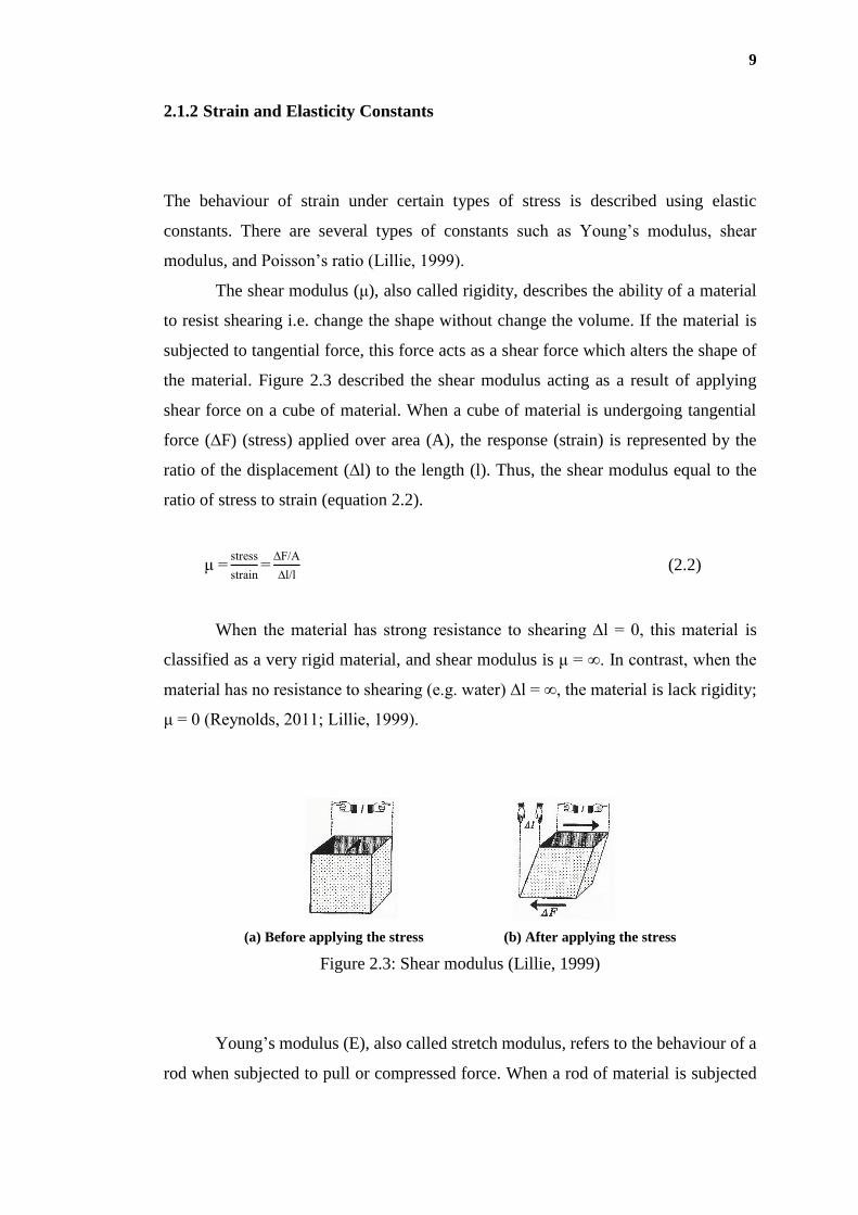
The shear modulus (μ), also called rigidity, describes the ability of a material
to resist shearing i.e. change the shape without change the volume. If the material is
subjected to tangential force, this force acts as a shear force which alters the shape of
the material. Figure 2.3 described the shear modulus acting as a result of applying
shear force on a cube of material. When a cube of material is undergoing tangential
force (∆F) (stress) applied over area (A), the response (strain) is represented by the
ratio of the displacement (∆l) to the length (l). Thus, the shear modulus equal to the
ratio of stress to strain (equation 2.2).
μ =stress
strain=
∆F/A
∆l/l ( 2.2 )
When the material has strong resistance to shearing ∆l = 0, this material is
classified as a very rigid material, and shear modulus is μ = ∞. In contrast, when the
material has no resistance to shearing (e.g. water) ∆l = ∞, the material is lack rigidity;
μ = 0 (Reynolds, 2011; Lillie, 1999).
(a) Before applying the stress (b) After applying the stress
Figure 2.3: Shear modulus (Lillie, 1999)
Young’s modulus (E), also called stretch modulus, refers to the behaviour of a
rod when subjected to pull or compressed force. When a rod of material is subjected

10
to force (F) acting over the cross-sectional area (i.e. longitudinal stress), the strain is
the ratio of changing on length (∆Lr) to the original length (Lr) as shown in Figure 2.4.
Young’s modulus E is estimated in equation 2.3:
E =stress
strain=
F/A
∆Lr/Lr ( 2.3 )
(a) Before stress is applied (b) After stress is applied
Figure 2.4: Young’s modulus (Lillie, 1999)
Poisson’s ratio (ν) is the ratio between the amount of shortening experienced
by a cube of material in the direction of an applied compression and the expansion that
takes place at right angles to it. Poisson’s ratio has a range for most material from 0 to
0.5 where the value 0.5 is for a completely incompressible material and at undrained
condition (Megson, 2014; Knappett & Craig, 2012; Lillie, 1999). Poisson’s ratio for a
stretched rod is the ratio of transverse strain (∆W/W) to longitudinal strain (∆Lr/Lr) as
shown in equation 2.4. Young’s modulus (E), shear modulus (G), and Poisson’s ratio
(v) are linked through equation 2.5.
ν = - ∆W/W
∆Lr/Lr ( 2.4 )
G =E
2(1 + ν) ( 2.5 )
Where ∆W is the amount of the decrease in width, W the original width of the
rod.
11
2.1.3 Seismic Waves
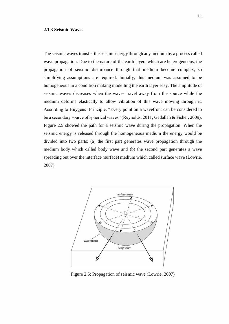
The seismic waves transfer the seismic energy through any medium by a process called
wave propagation. Due to the nature of the earth layers which are heterogeneous, the
propagation of seismic disturbance through that medium become complex, so
simplifying assumptions are required. Initially, this medium was assumed to be
homogeneous in a condition making modelling the earth layer easy. The amplitude of
seismic waves decreases when the waves travel away from the source while the
medium deforms elastically to allow vibration of this wave moving through it.
According to Huygens’ Principle, “Every point on a wavefront can be considered to
be a secondary source of spherical waves” (Reynolds, 2011; Gadallah & Fisher, 2009).
Figure 2.5 showed the path for a seismic wave during the propagation. When the
seismic energy is released through the homogeneous medium the energy would be
divided into two parts; (a) the first part generates wave propagation through the
medium body which called body wave and (b) the second part generates a wave
spreading out over the interface (surface) medium which called surface wave (Lowrie,
2007).
Figure 2.5: Propagation of seismic wave (Lowrie, 2007)

12
2.1.4 Body Wave
Body wave propagates through the internal mass of the elastic medium. The two kinds
of seismic body wave are primary waves (P-wave) and secondary waves (S-wave). P-
wave is called primary wave because P-wave is the first arrival from earthquakes while
S-wave arrive in the second place. In addition, P-wave is called compression wave
because the particles vibrate in series of compressions and rarefactions, however, this
wave is applicable in the air, water, and solid. P-wave is also called push-pull and
longitudinal waves because particles of the material move back and forth, parallel to
the direction of the wave is moving (Figure 2.6 and Figure 2.7). In the primary wave,
the particle motion associated with the passage of a compression wave involves
oscillation and is subjected to two types of force; compression and dilatation
successively (Figure 2.7) (Lutgens & Tarbuck, 2012; Kearey et al., 2002).
Figure 2.6: P-wave propagation method (Lillie, 1999)
Figure 2.7: Elastic deformations and ground particle motions associated with the
passage of primary wave P-wave (Kearey et al., 2002)
On the other side, the secondary waves (S-wave) (i.e. shear, transverse, or
shake waves) are generated when the particles are vibrating at right angles to the

13
direction of energy flow. Many literatures reported that the S-wave travels slower than
P-wave (Lowrie, 2007; Gadallah & Fisher, 2005; Lillie, 1999). Moreover, the
propagation of S-wave depends on a pure shear strain in a direction perpendicular to
the direction of wave travel. Thus, the S-wave has no ability to vibrate in liquid or air
because of this medium has no shear strength (Figure 2.8 and Figure 2.9).
Figure 2.8: S-wave propagation method (Lillie, 1999)
Figure 2.9: Elastic deformations and ground particle motions associated with the
passage of shear wave S-wave (Kearey et al., 2002)
2.1.5 Surface Wave
Surface waves propagate when there is a free boundary at the medium such as surface
earth. The disturbance caused by the seismic wave is larger at the surface and decreases
exponentially with the depth (Everett, 2013; Reynolds, 2011). The two main types of
surface wave are Rayleigh and Love waves. Figure 2.10 illustrated the movement
nature of the main waves; P-wave, S-wave, Rayleigh, and Love waves. Even though
the primary wave and secondary wave travel faster than Rayleigh and Love waves, in
normal circumstances Rayleigh and Love waves carry more than two-thirds of the total
seismic energy generated by a compression source and hence is converted to Rayleigh
waves, which are the main component of the ground roll (Milsom & Eriksen, 2011).

14
Figure 2.10: Particle motions due to different types of seismic waves (Lillie, 1999)
Rayleigh waves have a retrograde elliptical motion. At the top of the ellipse,
particles move opposite to the direction or wave propagation. While Love waves are
surface waves that behave like shear waves in the horizontal plane where the wave
reflected between surface layer has higher velocities underlying layers with lower
velocity. The Rayleigh wave produces more information than the Love wave, which
gives the advantage to using Rayleigh waves more frequently compare with Love
waves. In addition, Rayleigh waves are more important in engineering concept where
the shear wave can be predicted through Rayleigh wave value (Milsom & Eriksen,
2011; Wightman et al., 2003).
2.1.6 Seismic Velocities
The seismic velocities on rocks and soils are measured through the capability of the
seismic wave to propagate through this medium at specific travel time. The particles
of the medium (e.g. soils and rocks) are forced into oscillation by the transmitted
energy of seismic waves. Figure 2.11 illustrated the different ways of body and surface
waves (P-wave, S-wave, Rayleigh, and Love waves) travelling through geological
structural and their relative velocity. For most geological materials, the Rayleigh wave
velocity (VR) is between 0.91 to 0.955 of shear wave velocity (VS) which is about half

15
of primary wave velocity (VP). While Love wave velocity is the slowest wave among
all four. Meanwhile, and under any condition, VS do not exceed more than 70% of VP
(Everett, 2013; Milsom & Eriksen, 2011; Reynolds, 2011).
It is observed that Rayleigh waves disperse with respect to the depth. The
Rayleigh wave is subjected to cumulative change during the propagation because of
the different frequency components travelling at different velocities. Meanwhile,
decreasing the applied frequency leads to increase in the wavelength thus increasing
the penetrated depth for the Rayleigh wave (Milsom & Eriksen, 2011). This dispersion
is directly attributable to velocity variation with depth in the earth’s interior (which
were produced by earthquake waves). The same methodology is used by applying
active source (e.g. sledgehammer) to study near surface materials for civil engineering
investigations.
Figure 2.11: Body and surface seismic waves movement and velocities (Milsom &
Eriksen, 2011)
The wave velocity has many applications which express many properties of the
soils and rocks. Figure 2.12 showed using wave velocities by correlating P-wave to
the ripabilities in the construction of different engineering projects upon the common
rocks. While Table 2.1 showed values of VS for common geological materials rock
(Milsom & Eriksen, 2011).

16
Figure 2.12: Primary wave velocity versus ripabilities in common rocks (Milsom &
Eriksen, 2011)
Table 2.1: Typical shear wave velocity for some common materials
Material VS (m/s)
Soft mud <200
Dry sand 300–600
Wet sand 700–900
Clays 500–800
Tills 1000–1200
Sandstone 1600–2600
Shale 2200–2400
Limestone 2500–3100
Granite 3200–3800
Basalt 3400–4000
Source: Milsom & Eriksen (2011)

17
Many basic relationships between the different types of elastic velocities and
elasticity parameters were solved mathematically and provided a desirable
accessibility to estimate more engineering properties for soils and rocks. For example,
for any elastic wave velocity (V), the square root of an elastic modulus divided by the
square root of density (ρ) is expressing the seismic wave velocity. The P-wave was
connected to the maximum Young’s modulus (Emax) while S-wave was connected to
the maximum shear modulus (Gmax) (see equations 2.6 to 2.8) (Mavko et al., 2009;
Robinson & Coruh, 1988).
VE =√Emax
ρ ( 2.6 )
VS =√Gmax
ρ =√
E
2 ρ(1+ ν) ( 2.7 )
VP =√K + 4 3⁄ Gmax
ρ =√
E
ρ [
1- ν
(1 - 2ν) (1 + ν)] ( 2.8 )
Where VE is the extensional wave velocity in the narrow bar, Vs is the shear
wave velocity, Vp is the compression wave velocity, and ν is the Poisson’s ratio.
According to equations 2.6, 2.7, and 2.8, the velocity decreased with the
increase of the density ρ and the velocity decreased with depth (due to increasing the
density with the depth). However, despite increasing the density with the depth, the
velocity usually increases with the depth. That was due to the rapid increase in the
elastic constant compared with the increase in the density. It has one exception, salt is
the only common rock with a high velocity but a low density (Milsom & Eriksen,
2011).
For an elastic, isotropic, and unbounded material, seismic velocities depend on
the elastic constants (Gmax, Emax and ν) and the density (ρ) of the material. Otherwise,
if ρ, VP, VE, and VS of a rock or soil are known, most of the elastic constants are
calculated using equations 2.9 to 2.14 (Murillo et al., 2011; Mavko, 2009; Robinson
& Coruh, 1988).
Gmax = ρ Vs
2 ( 2.9 )
18
Emax = ρ VE
2 ( 2.10 )
Emax = ρ VS
2(3 Vp
2- 4Vs
2)
Vp2- Vs
2 ( 2.11 )
ν = Vp
2- 2Vs
2
2(Vp2- Vs
2) ( 2.12 )
VP
VS
= Emax
Gmax
= 2 (1 – ν)
(1 - 2ν)=√
K
Gmax
+ 4
3 ( 2.13 )
ν = [2 - (Vp/VS)2]
2 [1- ( Vp/VS)2] ( 2.14 )
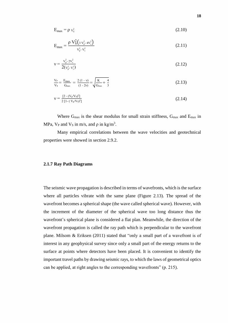
Where Gmax is the shear modulus for small strain stiffness, Gmax and Emax in
MPa, VP and VS in m/s, and ρ in kg/m3.
Many empirical correlations between the wave velocities and geotechnical
properties were showed in section 2.9.2.
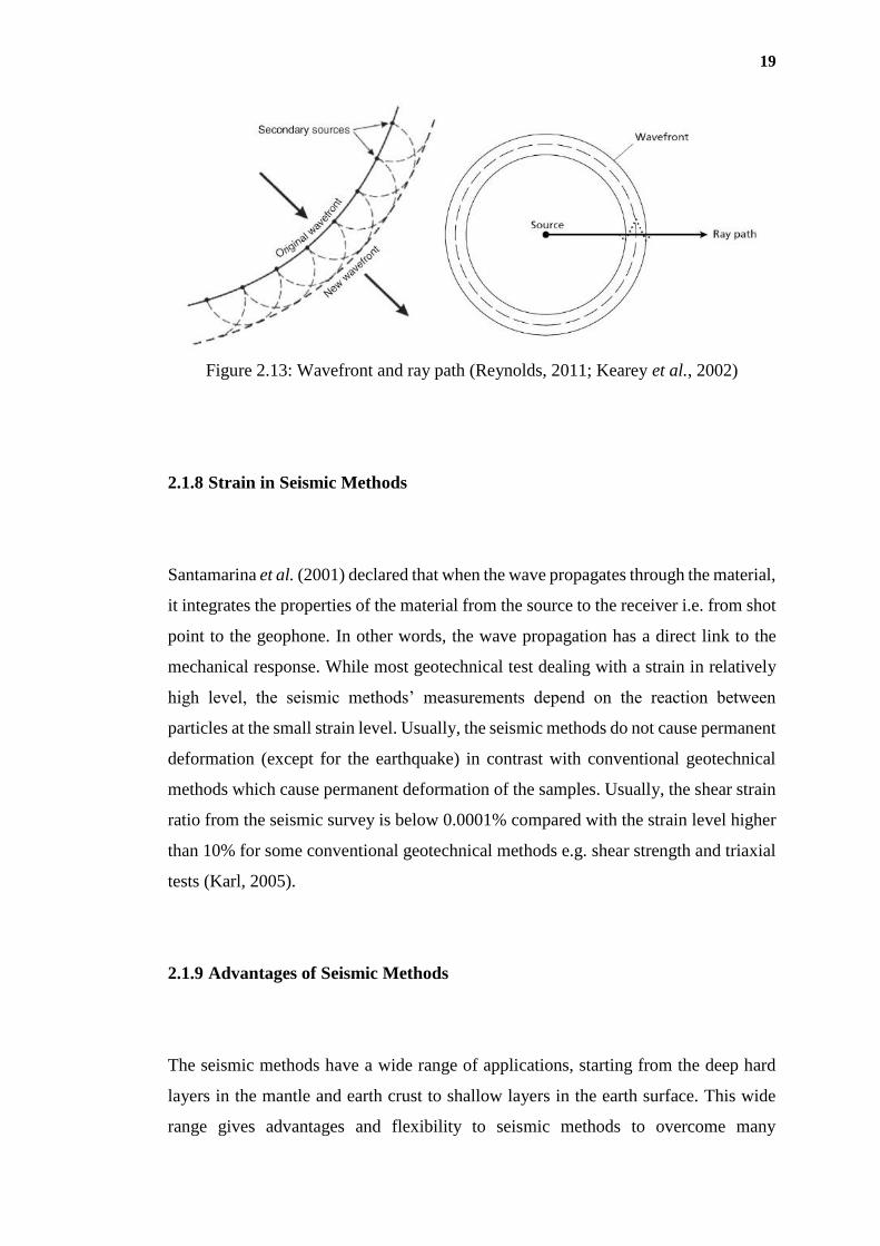
2.1.7 Ray Path Diagrams
The seismic wave propagation is described in terms of wavefronts, which is the surface
where all particles vibrate with the same plane (Figure 2.13). The spread of the
wavefront becomes a spherical shape (the wave called spherical wave). However, with
the increment of the diameter of the spherical wave too long distance thus the
wavefront’s spherical plane is considered a flat plan. Meanwhile, the direction of the
wavefront propagation is called the ray path which is perpendicular to the wavefront
plane. Milsom & Eriksen (2011) stated that “only a small part of a wavefront is of
interest in any geophysical survey since only a small part of the energy returns to the
surface at points where detectors have been placed. It is convenient to identify the
important travel paths by drawing seismic rays, to which the laws of geometrical optics
can be applied, at right angles to the corresponding wavefronts” (p. 215).
19
Figure 2.13: Wavefront and ray path (Reynolds, 2011; Kearey et al., 2002)
2.1.8 Strain in Seismic Methods
Santamarina et al. (2001) declared that when the wave propagates through the material,
it integrates the properties of the material from the source to the receiver i.e. from shot
point to the geophone. In other words, the wave propagation has a direct link to the
mechanical response. While most geotechnical test dealing with a strain in relatively
high level, the seismic methods’ measurements depend on the reaction between
particles at the small strain level. Usually, the seismic methods do not cause permanent
deformation (except for the earthquake) in contrast with conventional geotechnical
methods which cause permanent deformation of the samples. Usually, the shear strain
ratio from the seismic survey is below 0.0001% compared with the strain level higher
than 10% for some conventional geotechnical methods e.g. shear strength and triaxial
tests (Karl, 2005).
2.1.9 Advantages of Seismic Methods
The seismic methods have a wide range of applications, starting from the deep hard
layers in the mantle and earth crust to shallow layers in the earth surface. This wide
range gives advantages and flexibility to seismic methods to overcome many

20
restrictions (e.g. land contamination, the high cost of sampling, time limitation, and
difficulties during the sampling) when the geotechnical methods become inapplicable
(Foti, 2013; Matasovica et al., 2006).
Wightman et al. (2003) briefly summarised advantages of the seismic methods
as follows: (1) decreasing the cost by avoiding sampling; (2) investigating large area
in relatively short time; and (3) with proper method and suitable analysis, it can gain
useful data to be used in design particularly for highway projects.
2.2 Seismic Methods
The seismic methods are classified as field or laboratory methods (see Figure 2.14).
The seismic refraction, reflection, surface wave analysis, and borehole are considered
seismic field methods, and the main function is to measure the seismic wave velocity.
The seismic field methods are classified further to surface methods (e.g. seismic
refraction, seismic reflection, and surface wave analysis) and borehole methods (e.g.
seismic crosshole, downhole, and suspension). In surface methods, seismic refraction
(SR) and seismic reflection (SRl) methods depend on the measurement of the refracted
and reflected body waves respectively while surface wave analysis depends on the
measurements of the surface wave from the ground surface. The seismic borehole
methods (BHS) measure the wave velocity at the medium between the several holes
or a single hole e.g. seismic crosshole method and seismic downhole method
respectively (Mok et al., 2016; Benson & Yuhr, 2015).
The laboratory seismic methods usually involve several methods including the
ultrasonic and bender element. The ultrasonic method is usually applied on the
consolidated material while the bender element (BE) is applied on unconsolidated
materials (Mavko et al., 2009).

21
Figure 2.14: Seismic methods
2.2.1 Field Seismic Methods
The field seismic methods are categorised in many ways, for example; (a) according
to the target depth; it is classified as shallow or deep investigation seismic survey, and
(b) according to the used technique, it is classified as refraction, reflection, seismic
borehole, and analysis surface wave methods (Foti et al., 2014; Reynolds, 2011). Some
of the field seismic methods, the interpretations, and the cautions when using these
methods were described in brief at the following sections.
2.2.1.1 Seismic Surface Methods
Any acquisition of seismic data from the surface are considered as seismic surface
methods e.g. seismic refraction, reflection, and surface wave analysis. The seismic
reflection and refraction methods are the most used seismic methods due to their
relationship with oil exploration. Thus, advancing these methods such as the
development of powerful tools for acquisitions and analysis of reflection and refraction
data. The main function for both methods is to measure the velocities of P-wave and
Seismic methods
Laboratory Field
Surface Borehole Ultrasonic Bender element
Body wave Surface wave
Crosshole Downhole Suspension
Refraction Reflection SASW CSW ReMi MASW

22
S-wave (Simm et al., 2014). The measurement of the VP and VS is usually used to
predict several engineering properties (refer to section 2.1.6).
Figure 2.15 showed a simple illustration of reflection and refraction of the
seismic waves. According to Snell’s law (equation 2.15), both reflecting or refracting
seismic wave’s behaviour depend on the angle of incidence wave (θi) and the
differential in the dynamic properties of the layers e.g. elasticity modulus and density
(Everett, 2013; Milsom & Eriksen, 2011; Lillie, 1999).
sin θi
sin θ2=
V1
V2
= sin θc ( 2.15 )
Where θ2 is the incidence angle for the second layer, θc is the critical angle, V1
is the velocity at first layer, and V2 is the velocity at the second layer.
Figure 2.15: Reflected and refracted wave in Snell’s law
In the last decade, the near surface exploration (i.e. surface wave analysis) had
been used frequently. Many methods were developed to satisfy the needs of near
surface range. The main advantage of these methods is the ability to explore the
shallow depth (less than 100 m) with low cost compared with conventional reflection
and refraction methods which are lower than the relative expensive borehole log
methods. The effective depth of most surface wave methods as reported by Foti et al.
(2014), Fabien-Ouellet & Fortier (2014), and Ayolabi & Adegbola (2014) was less
than 30 m, while Ni et al. (2014) reported less than 27 m, Reynolds (2011) reported
less than 20 m, and Park et al. (2002) reported less than 50 m.
Layer 1, V1
Layer 2, V2 V2 > V1
Geophone Geophone
θi θi θc θc
θ2 θ2
Second layer surface
Earth surface

23
In surface wave analysis methods, passive and active sources of wave
generators (i.e. producers) are used. If the waves come from urban activity (e.g.
vehicles movement and drilling activities) or naturally (e.g. the wind and small
earthquake vibrations), it accounts as a passive source. On the other hand, if the source
under controlling (e.g. hammer, vibrator, airgun), it accounts as an active source
(Everett, 2013; Milsom & Eriksen, 2011).
Although the damping influences the recording data at seismic surface wave
methods, this attenuation is considered as a guide to explain the nature of the earth
layers (Everett, 2013; Santamarina et al., 2005). This is one of the advantages of using
the seismic surface wave methods.
Milsom & Eriksen (2011) declared that “Of the two, (Rayleigh and Love
waves) the Rayleigh waves are the most important in engineering geophysics, as their
velocities are related to those of the shear waves in the same elastic media. The exact
relationship depends on the Poisson ratio, approximating shear wave velocities by
Rayleigh wave velocities, even without applying a correction factor, thus introduces
an error of less than 10% across a range of materials”. The main function of measuring
surface waves is to determine the Rayleigh waves which are commonly named ground
roll. The Rayleigh wave is controlled by the function of the frequency where the low
frequency means long wavelength and deeper penetration. Thus, controlling the
frequency and increasing the amplitude (to improve the required energy to penetrate
and avoid attenuation) improved the quality of acquisition data (Foti et al., 2014;
Everett, 2013).
Previous researchers declared that for any surface method, low frequency (i.e.
long wavelength) of surface waves penetrated deeper into the earth and showed greater
phase velocities, and was more sensitive to the elastic properties of the deeper layer.
Otherwise, high frequency (i.e. short wavelength) surface waves were more sensitive
to the physical properties of the more upper layers. For each frequency in surface wave
methods, there was unique phase velocity for each unique wavelength. For this reason,
each surface wave mode (e.g. fundamental and high mode) possessed a unique phase
velocity for each unique wavelength (Foti et al., 2014; Reynolds, 2011).
The development of analysis surface wave velocity led to the development of
several surface wave analysis methods. These methods were described and illustrated
as follows:

24
(1) Spectral analysis of surface waves (SASW), has one source (hammer produce
board of frequency), a pair geophone (Figure 2.16).
(2) Continuous surface wave (CSW), has one source (mono-frequency), a pair
geophone (Figure 2.17).
(3) Refraction microtremor (ReMi), has passive source, multi-geophone (Figure
2.18).
(4) Multi-channel analysis of surface waves (MASW), has active sources, multi-
geophone. (Figure 2.19).
Figure 2.16: Spectral analysis of surface waves method (SASW)
Figure 2.17: Continuous surface waves seismic method (CSW)
Figure 2.18: Refraction Microtremor Method (ReMi)
Active source (hammer)
Geophone
Active source (vibrator)
Geophone
Passive source
Geophone

214
REFERENCES
Agan, C. & Algin, H. M. (2014). Determination of Relationships Between Menard
Pressuremeter Test and Standard Penetration Test Data using ANN model: a
Case Study on the Clayey Soil in Sivas, Turkey. Geotechnical Testing Journal,
37(3): 1-12. DOI:10.1520/GTJ20130123
Alramahi, B. (2007). Characterization of Unsaturated Soils Using Elastic and
Electromagnetic Waves. Louisiana State University. Ph.D. thesis.
Alshameri, B. (2011). Engineering Properties of Older Alluvial. Universiti Teknologi
Malaysia. Malaysia. Master Thesis.
Alvarado, G. & Coop, M. R. (2012). On the performance of bender elements in triaxial
tests. Géotechnique, 62(1): 1-17. DOI 10.1680/geot.7.00086.
Amat, A. S. (2007). Elastic Stiffness Moduli of Hostun Sand. Project Report.
Department of Civil Engineering, University of Bristol, UK.
American Society for Testing and Materials (2005). Standard Test Methods for
Laboratory Determination of Water (Moisture) Content of Soil and Rock by
Mass. ASTM International, West Conshohocken, PA, USA. D2216.
American Society for Testing and Materials (2006). Standard Guide for Using the
Seismic Refraction Method for Subsurface Investigation. United States. D5777.
American Society for Testing and Materials (2007). Standard Test Method for Particle
Size Analysis of Soils. ASTM International, West Conshohocken, PA, USA.
D422.
American Society for Testing and Materials (2007). Standard Test Method for
Consolidated Undrained Direct Simple Shear Testing of Cohesive Soils. ASTM
International, West Conshohocken, PA, USA. D6528.

215
American Society for Testing and Materials (2008). Standard Test Method for
Laboratory Determination of Pulse Velocities and Ultrasonic Elastic Constants
of Rock. ASTM International, West Conshohocken, Pennsylvania. D2845.
American Society for Testing and Materials (2010). Standard Test Methods for
Specific Gravity of Soil Solids by Water Pycnometer. ASTM International, West
Conshohocken, PA, USA. D854.
American Society for Testing and Materials (2011). Standard Test Methods for Direct
Shear Test of Soils Under Consolidated Drained Conditions. ASTM
International, West Conshohocken, PA, USA. D3080.
American Society for Testing and Materials (2012). Standard Test Methods for
Laboratory Compaction Characteristics of Soil Using Standard Effort (12400
ft-lbf/ft3 (600 kN-m/m3)). ASTM International, West Conshohocken, PA, USA.
D698.
American Society for Testing and Materials (2012). Standard Test Methods for
Laboratory Compaction Characteristics of Soil Using Modified Effort (56,000
ft-lbf/ft3 (2,700 kN-m/m3)). ASTM International, West Conshohocken, PA, USA.
D1557.
Amšiejus, J., Dirgėlienė, N., Norkus, A. & Skuodis, Š. (2014). Comparison of sandy
soil shear strength parameters obtained by various construction direct shear
apparatuses. Archives of civil and mechanical engineering, 14(2): 327-334. DOI:
10.1016/j.acme.2013.11.004.
Anderson, N. Ismail, A. & Davisc, C. (2006a). Selection of Appropriate Geophysical
Techniques: A Generalized Protocol Based on Engineering Objectives and Site
Characteristics. Proc., 2006 Highway Geophysics- NDE Conference, 2006, pp.
29–47.
Anderson, N. Thitimakorn, T. Hoffman, D. Stephenson, R. & Luna, R. (2006b).
Comparison of Four Geophysical Methods for Determining the Shear Wave
Velocity of Soils. 6th International Conference and Exposition on Petroleum
Geophysics. Kolkata. India. 2006. pp. 1002-1007.
Aris, M., Benahmed, N. & Bonelli, S. (2012). Experimental Geomechanics: A
Laboratory Study on the Behaviour of Granular Material Using Bender
Elements. European Journal of Environmental and Civil Engineering, 16(1): 97-
110.

216
Arosio, D., Longoni, L., Papini, M. & Zanzi, L. (2013). Seismic characterization of an
abandoned mine site. Acta Geophysica, 61(3): 611-623.
Arroyo, M. (2007). Wavelet Analysis of Pulse Tests in Soil Samples. Ital. Geotech. J,
30, 26-38.
Arroyo, M., Greening, P. D. & Muir-Wood, D. (2003b). An estimate of uncertainty in
current laboratory pulse test practice. Rivista Italiana di Geotecnica, 37(1): 17-
35.
Arroyo, M., Medina, L. & Muir Wood, D. (2002). Numerical Modelling of Scale
Effects in Bender-Based Pulse Tests. NUMOG VIII, Pande, GN and
Pietruszczak, S. (eds): 589-594.
Arroyo, M., Muir Wood, D. & Greening, P. D. (2003a). Source near-field effects and
pulse tests in soil samples. Géotechnique, 53(3): 337-345.
Arroyo, M., Wood, D.M., Greening, P.D., Medina, L. & Rio, J. (2006). Effects of
sample size on bender-based axial G0 measurements. Géotechnique, 56(1),
pp.39-52. DOI: 10.1680/geot.2006.56.1.39.
Arulnathan, R., Boulanger, R. W. & Riemer, M. F. (1998). Analysis of Bender
Element Tests. Geotechnical Testing Journal, GTJODJ, 21(2): 120-131.
Arulnathan, R., Boulanger, R. W., Kutter, B. L. & Sluis, W. K. (2000). New Tool for
Shear Wave Velocity Measurements in Model Tests. Geotechnical testing
journal, 23(4): 444-453.
Atkinson, J. (1993). An Introduction to the Mechanics of Soils and Foundations:
Through Critical State Soil Mechanics. London. McGraw-Hill International
Series in Civil Engineering.
Atkinson, J. (2007). The mechanics of soils and foundations. 2nd ed. London and New
York. CRC Press.
Ayolabi, E. A. & Adegbola, R. B. (2014). Application of MASW in road failure
investigation. Arabian Journal of Geosciences, 7(10): 4335-4341.
Bai, F. Q. & Liu, S. H. (2012). Measurement of the shear strength of an expansive soil
by combining a filter paper method and direct shear tests. Geotechnical Testing
Journal, 35(3): 451-459. DOI: 10.1520/GTJ103342.
Bartake, P., Patel, A. & Singh, D. (2008). Instrumentation for Bender Element Testing
of Soils. International Journal of Geotechnical Engineering, 2(4): 395-405. DOI
10.3328/IJGE.2008.02.04.393-404.

217
Bartake, P.P. & Singh, D.N. (2007). Studies on Determination of Shear Wave Velocity
in Sands. Geomechanics and Geoengineering: An International Journal, 2(1):
41-49.
Bate, B., Choo, H. & Burns, S. E. (2013). Dynamic properties of fine-grained soils
engineered with a controlled organic phase. Soil Dynamics and Earthquake
Engineering, 53, 176-186. doi: 10.1016/j.soildyn.2013.07.005.
Baziw, E. & Verbeek, G. (2014). Methodology for Processing Seismograms
Containing Total Internal Reflections. Geoscience and Remote Sensing, IEEE
Transactions on, 52(11): 7073-7085.
Baziw, E. J. (1993). Digital filtering techniques for interpreting seismic cone data.
Journal of geotechnical engineering, 119(6): 998-1018.
Belkhatir, M., Arab, A., Della, N., Missoum, H. & Schanz, T. (2010). Influence of
inter-granular void ratio on monotonic and cyclic undrained shear response of
sandy soils. Comptes Rendus Mecanique, 338(5): 290-303.
DOI:10.1016/j.crme.2010.04.002.
Belkhatir, M., Schanz, T., Arab, A. & Della, N. (2014). Experimental Study on the
Pore Water Pressure Generation Characteristics of Saturated Silty Sands.
Arabian Journal for Science and Engineering, 39(8): 6055-6067. DOI
10.1007/s13369-014-1238-9.
Bellotti, R., Jamiolkowski, M., Presti, D. L. & O'neill, D. A. (1996). Anisotropy of
Small Strain Stiffness in Ticino Sand. Geotechnique, 46(1): 115-131.
Benson, R. C. & Yuhr, L. B. (2015). Site Characterization in Karst and Pseudokarst
Terraines: Practical Strategies and Technology for Practicing Engineers,
Hydrologists and Geologists. New York London Springer.
Bensoula, M., Missoum, H. & Bendani, K. (2015). Critical undrained shear strength
of loose-medium sand-silt mixtures under monotonic loadings. Journal of
Theoretical and Applied Mechanics, 53(2): 331-344. DOI: 10.15632/jtam-
pl.53.2.331.
Blewett, J., Blewett, I. J. & Woodward, P. K. (1999). Measurement of Shear-Wave
Velocity Using Phase-Sensitive Detection Techniques. Canadian geotechnical
journal. 36(5): 934–939.
Blewett, J., Blewett, I. J. & Woodward, P. K. (2000). Phase and Amplitude Responses
Associated with the Measurement of Shear-Wave Velocity in Sand by Bender

218
Elements. Canadian Geotechnical Journal. 37(6): 1348-1357. DOI 10.1139/t00-
047.
Boulanger, R. W., Arulnathan, R., Jr, L. F. H., Torres, R. A. & Driller, M. W. (1998).
Dynamic properties of Sherman Island peat. Journal of Geotechnical and
Geoenvironmental Engineering, 124(1): 12-20.
Brandenberg, S. J., Choi, S., Kutter, B. L., Wilson, D. W. & Santamarina, J. C. (2006).
A Bender Element System for Measuring Shear Wave Velocities in Centrifuge
Models. In Zhang and Wang (Eds) Physical Modleing in Geotechnics–6th
ICPMG–Ng. pp. 165-170.
Brignoli, E. G. M., Gotti, M. & Stokoe, K. H. (1996). Measurement of Shear Waves
in Laboratory Specimens by Means of Piezoelectric Transducers. Geotechnical
testing journal, 19(4): 384-397.
Burns, S. E. & Mayne, P. W. (1996). Small-And High-Strain Measurements of In-Situ
Soil Properties Using the Seismic Cone Penetrometer. Transportation Research
Record: Journal of the Transportation Research Board, 1548(1): 81-88.
Camacho-Tauta, J. F. (2011). Evaluation of the small-strain stiffness of soil by non-
conventional dynamic testing methods. Instituto Superior Técnico, PhD thesis.
Camacho-Tauta, J. F., Álvarez, J. D. J. & Reyes-Ortiz, O. J. (2012). A Procedure to
Calibrate and Perform the Bender Element Test. Dyna, 79(176): 10-18.
Capizzi, P. & Martorana, R. (2014). Integration of constrained electrical and seismic
tomographies to study the landslide affecting the cathedral of Agrigento. Journal
of Geophysics and Engineering, 11(4): 045009.
Carpenter, P. J., Reddy, K. R. & Thompson, M. D. (2012). Seismic Imaging of a
Leachate-Recirculation Landfill: Spatial Changes in Dynamic Properties of
Municipal Solid Waste. Journal of Hazardous, Toxic, and Radioactive Waste,
17(4): 331-341.
.
Castellaro, S., Panzeri, R., Mesiti, F. & Bertello, L. (2015). A surface seismic approach
to liquefaction. Soil Dynamics and Earthquake Engineering, 77, 35-46.
Cerato, A. B. & Lutenegger, A. J. (2006). Specimen size and scale effects of direct
shear box tests of sands. Geotechnical Testing Journal, 29(6): 507.
Cha, M. & Cho, G. (2007). Shear Strength Estimation of Sandy Soils Using Shear
Wave Velocity. Geotechnical Testing Journal, 30(6). GTJ100011 1-12.
doi:10.1520/GTJ100011.

219
Chanda, M. & Roy, S. K. (2007). Plastics technology handbook. 4th ed. London &
New York. CRC press.
Chang, I. H., Cho, G. C., Lee, J. G. & Kim, L. H. (2006). Characterization of clay
sedimentation using piezoelectric bender elements. In Key Engineering
Materials, 321, 1415-1420.
Chang, K. T., Kang, Y. M., Ge, L. & Cheng, M. C. (2015). Mechanical Properties of
Gravel Deposits Evaluated by Nonconventional Methods. Journal of Materials
in Civil Engineering, 27(11): 04015032. doi:10.1061/(ASCE)MT.1943-
5533.0001287.
Chang, W. J., Chang, C. W. & Zeng, J. K. (2014). Liquefaction characteristics of gap-
graded gravelly soils in K 0 condition. Soil Dynamics and Earthquake
Engineering, 56, 74-85. doi:10.1016/j.soildyn.2013.10.005.
Chapman, C. (2004). Fundamentals of Seismic Wave Propagation. London & New
York. Cambridge University Press.
Chen, X., Zhang, J., Xiao, Y. & Li, J. (2015). Effect of roughness on shear behavior
of red clay–concrete interface in large-scale direct shear tests. Canadian
Geotechnical Journal, 52(8): 1122-1135. DOI: 10.1139/cgj-2014-0399.
Chenari, R. J., Tizpa, P., Rad, M. R. G., Machado, S. L. & Fard, M. K. (2015). The
use of index parameters to predict soil geotechnical properties. Arabian Journal
of Geosciences, 8(7): 4907-4919. DOI 10.1007/s12517-014-1538-0.
Chinkulkijniwat, A., Man-Koksung, E., Uchaipichat, A. & Horpibulsuk, S. (2010).
Compaction characteristics of non-gravel and gravelly soils using a small
compaction apparatus. Journal of ASTM International, 7(7).
Choo, H. & Burns, S. E. (2015). Shear wave velocity of granular mixtures of silica
particles as a function of finer fraction, size ratios and void ratios. Granular
Matter, 17(5): 567-578. DOI: 10.1007/s10035-015-0580-2.
Choo, H., Yeboah, N. N. & Burns, S. E. (2016). Small to intermediate strain properties
of fly ashes with various carbon and biomass contents. Canadian Geotechnical
Journal, 53(1): 35-48. doi:10.1139/cgj-2014-0069.
Choudhury, D. & Savoikar, P. (2009). Simplified method to characterize municipal
solid waste properties under seismic conditions. Waste management, 29(2): 924-
933.
Clariá, J. J. & Rinaldi, V. A. (2007). Shear wave velocity of a compacted clayey silt.
Geotechnical Testing Journal, 30(5): 1-10. doi:10.1520/GTJ100655.

220
Clayton, C. R. I., Theron, M. & Best, A. I. (2004). The measurement of vertical shear-
wave velocity using side-mounted bender elements in the triaxial apparatus.
Géotechnique, 54(7): 495-498. DOI 10.1680/geot.2004.54.7.495.
Connolly, T. M. & Kuwano, R. (1999). The measurement of G^ in a resonant column,
bender element, torsional shear apparatus, In Jamiolkowski, M. B., Lancellotta,
R. & Presti, D. L. (Eds.). (1999). Pre-Failure Deformation of Geomaterials:
Proceedings International Symposium, Torino, Italy (Vol. 1, p. 73). CRC Press.
Cubrinovski, M. & Rees, S. (2008). Effects of fines on undrained behaviour of sands.
Geotechnical Earthquake Engineering and Soil Dynamics IV: pp. 1-11. doi:
10.1061/40975(318)91.
Dadkhah, R., Ghafoori, M., Ajalloeian, R. & Lashkaripour, G. R. (2010). The Effect
of scale direct shear test on the strength parameters of clayey sand in Isfahan
City, Iran. Journal of Applied Sciences(Faisalabad), 10(18): 2027-2033.
Das, B. & Sobhan, K. (2014). Principles of Geotechnical Engineering. 8th ed. USA.
Cengage Learning.
Day, R. W. (2010). Foundation Engineering Handbook: Design and Construction with
the 2009 International Building Code. 2nd ed. New York. McGraw-Hill.
De Alba, P., Baldwin, K., Janoo, V., Roe, G. U. & Celikkol, B. (1984). Elastic-Wave
Velocities and Liquefaction Potential. Geotechnical Testing Journal, 7 (2): 77-
87.
Duffy, B., Campbell, J., Finnemore, M. & Gomez, C. (2014). Defining fault avoidance
zones and associated geotechnical properties using MASW: a case study on the
Springfield Fault, New Zealand. Engineering Geology, 183, 216-229.
Ekwue, E. I. & Seepersad, D. (2015). Effect of soil type, peat, and compaction effort
on soil strength and splash detachment rates. Biosystems Engineering, 136, 140-
148. DOI: 10.1016/j.biosystemseng.2015.06.004.
El-Hussain, I., Mohamed, A. M. E., Deif, A., Al-Rawas, G., Al-Jabri, K. & Pekman,
G. (2014). Delineation of a paleo-channel utilizing integrated geophysical
techniques at the port of duqm area, sultanate of oman. Journal of Geophysics
and Engineering, 11(5): 055005.
El-Sekelly, W., Abdoun, T. & Dobry, R. (2012). Soil characterization in centrifuge
models through measurement of shear wave velocities using bender elements. In
GeoCongress 2012@ sState of the Art and Practice in Geotechnical Engineering
(pp. 2037-2047). ASCE.
221
El-Sekelly, W., Mercado, V., Abdoun, T., Zeghal, M. & El-Ganainy, H. (2013).
Bender elements and system identification for estimation of Vs. International
Journal of Physical Modelling in Geotechnics, 13(4): 111-121. DOI
10.1680/ijpmg.13.00004.
El-Sekelly, W., Tessari, A. & Abdoun, T. (2014). Shear wave velocity measurement
in the centrifuge using bender elements. Geotechnical Testing Journal, 37(4):
689-704.
Eseller-Bayat, E., Gokyer, S., Yegian, M. K., Deniz, R. O. & Alshawabkeh, A. (2013).
Bender Elements and Bending Disks for Measurement of Shear and
Compression Wave Velocities in Large Fully and Partially Saturated Sand
Specimens. Geotechnical testing journal, 36(2): 275-282.
Everett, M. E. (2013). Near-surface applied geophysics. UK. Cambridge University
Press.
Fabien-Ouellet, G. & Fortier, R. (2014). Using all seismic arrivals in shallow seismic
investigations. Journal of Applied Geophysics, 103, 31-42.
Farooq, K., Rogers, J. D. & Ahmed, M. F. (2015). Effect of Densification on the Shear
Strength of Landslide Material: A Case Study from Salt Range, Pakistan. Earth
Science Research, 4(1): 113. DOI: 10.5539/esr.v4n1p113.
Ferreira, C. (2008). The use of seismic wave velocities in the measurement of stiffness
of a residual soil. University of Porto. Ph.D. Thesis.
Ferreira, C., Martins, J. P. & Correia, A. G. (2014). Determination of the small-strain
stiffness of hard soils by means of bender elements and accelerometers.
Geotechnical and Geological Engineering, 32(6): 1369-1375. DOI
10.1007/s10706-013-9678-7.
Ferreira, C., Viana da Fonseca, A. & Santos, J. A. (2007). Comparison of Simultaneous
Bender Elements and Resonant-Column Tests on Porto Residual Soil and
Toyoura Sand. In Geomechanics: Laboratory Testing, Modeling and
Applications–A Collection of Papers of the Geotechnical Symposium in Rome
(pp. 16-17).
Fonseca, A. V., Ferreira, C. & Fahey, M. (2009). A Framework Interpreting Bender
Element Tests, Combining Time-Domain and Frequency-Domain Methods.
Geotechnical Testing Journal, 32(2): 91-107.

222
Foti, S. (2013). Combined Use of Geophysical Methods in Site Characterization. In
Coutinho, R. Q. & Mayne, P. W. (Eds.). Geotechnical and Geophysical Site
Characterization 4. London & New York. CRC Press. pp: 43-61.
Foti, S., Lai, C. G., Rix, G. J. & Strobbia, C. (2014). Surface wave methods for near-
surface site characterization. London & New York. CRC Press.
Francisca, F., Yun, T. S., Ruppel, C. & Santamarina, J. C. (2005). Geophysical and
geotechnical properties of near-seafloor sediments in the northern Gulf of
Mexico gas hydrate province. Earth and Planetary Science Letters, 237(3): 924-
939.doi:10.1016/j.epsl.2005.06.050.
Fu, L., Zeng, X. & Figueroa, J. L. (2004). Shear Wave Velocity Measurement in
Centrifuge Using Bender Elements. International Journal of Physical Modelling
in Geotechnics, 4(2): 1-11.
Gadallah, M. R. & Fisher, R. (2009). Exploration geophysics. Berlin Heidelberg.
Springer Science & Business Media.
Gadallah, M. R. & Fisher, R. L. (2005). Applied seismology: A comprehensive guide
to seismic theory and application. USA. PennWell Books.
Gajo, A., Fedel, A. & Mongiovi, L. (1997). Experimental Analysis of the Effects of
Fluid-Solid Coupling on the Velocity of Elastic Waves in Saturated Porous
Media. Géotechnique, 47(5): 993-1008.
Garg, A. & Ng, C. W. W. (2015). Investigation of soil density effect on suction induced
due to root water uptake by Schefflera heptaphylla. Journal of Plant Nutrition
and Soil Science, 178(4): 586-591. DOI: 10.1002/jpln.201400265.
Garga, V. K. & Madureira, C. J. (1985). Compaction Characteristics of River Terrace
Gravel. Journal of Geotechnical Engineering, 111(8): 987-1007.
Germaine, J. T. & Germaine, A. V. (2009). Geotechnical Laboratory Measurements
for Engineers. New Jersey, USA. John Wiley and Sons.
Germano, C. (2003). Flexure Mode Piezoelectric Transducers. Audio and
Electroacoustics, IEEE Transactions on. 19(1): 6.
Geotechnical Digital Systems [GDS] Ltd. (2014). Hampshire, RG27 9GR, UK. GDS
Bender Element System (GDSBES) Specification Trade Brochure.
Gratchev, I. B. & Sassa, K. (2015). Shear Strength of Clay at Different Shear Rates.
Journal of Geotechnical and Geoenvironmental Engineering, 141(5): 06015002.
DOI: 10.1061/(ASCE)GT.1943-5606.0001297.
223
Grit, M. & Kanli, A. I. (2016). Integrated Seismic Survey for Detecting Landslide
Effects on High Speed Rail Line at Istanbul–Turkey. Open Geosciences, 8(1):
161-173.
Gu, X., Yang, J., Huang, M. & Gao, G. (2015). Bender element tests in dry and
saturated sand: Signal interpretation and result comparison. Soils and
Foundations, 55(5): 951-962. DOI: 10.1016/j.sandf.2015.09.002.
Guérif, J. (1990). Factors Influencing Compaction-Induced Increases in Soil Strength.
Soil and Tillage Research, 16(1): 167-178.
Güllü, H. (2015). Unconfined compressive strength and freeze–thaw resistance of fine-
grained soil stabilised with bottom ash, lime and superplasticiser. Road
Materials and Pavement Design, 16(3): 608-634. DOI:
10.1080/14680629.2015.1021369.
Hamidi, A., Alizadeh, M. & Soleimani, S. M. (2009). Effect of particle crushing on
shear strength and dilation characteristics of sand-gravel mixtures. International
Journal of Civil Engineering, 7(1): 61-71.
Hamilton, E. L. (1976). Shear-Wave Velocity versus Depth in Marine Sediments: A
Review. Geophysics, 41(5): 985-996.
Hanzawa, H., Nutt, N., Lunne, T., Tang, Y. X., & Long, M. (2007). A comparative
study between the NGI direct simple shear apparatus and the Mikasa direct shear
apparatus. Soils and foundations, 47(1), 47-58.
Hardy, S., Zdravkovic, L. & Potts, D. M. (2002). Numerical Interpretation of
Continuously Cycled Bender Element Tests. NUMOG. Sweets and Zeitlinger,
595-600.
Hausmann, J., Steinel, H., Kreck, M., Werban, U., Vienken, T. & Dietrich, P. (2013).
Two-dimensional geomorphological characterization of a filled abandoned
meander using geophysical methods and soil sampling. Geomorphology, 201,
335-343.
Heitor, A., Indraratna, B. & Rujikiatkamjorn, C. (2013). Laboratory study of small-
strain behavior of a compacted silty sand. Canadian Geotechnical Journal,
50(2): 179-188. doi:10.1139/cgj-2012-0037.
Hlasko, H. A. & Zeng, X. (2010). Piezoelectric probe for measurement of soil stiffness.
International Journal of Pavement Engineering, 11(1): 25-35. DOI:
10.1080/10298430802465624.

224
Hoar, R. J. & Stokoe, K. H. (1978). Generation and Measurement of Shear Waves In-
Situ. Dynamic Geotechnical Testing, 654, 3.
Horn, R., Taubner, H., Wuttke, M. & Baumgartl, T. (1994). Soil physical properties
related to soil structure. Soil and Tillage Research, 30(2): 187-216.
Huang, Y. T., Huang, A. B., Kuo, Y. C. & Tsai, M. D. (2004). A Laboratory Study on
the Undrained Strength of a Silty Sand from Central Western Taiwan. Soil
Dynamics and Earthquake Engineering, 24(9): 733-743.
doi:10.1016/j.soildyn.2004.06.013.
Hunt, R. E. (2005). Geotechnical engineering investigation handbook. 2nd ed. London
& New York. CRC Press.
Hunt, R. E. (2007). Geologic hazards: a field guide for geotechnical engineers.
London & New York. CRC Press.
Indian Roads Congress (IRC) (2014). Guidelines on compaction equipment for road
works Indian. New Delhi, India.
Indraratna, B., Heitor, A. & Rujikiatkamjorn, C. (2012). Effect of compaction energy
on shear wave velocity of dynamically compacted silty sand soil. In A.
Jotisankasa, A. Sawangsuriya, S. Soralump & W. Mairaing (Eds.), 5th Asia-
Pacific Conference on Unsaturated Soils. Thailand. Kasetsart University. pp.
635-640.
Ismail, M. A., Sharma, S. S. & Fahey, M. (2005). A Small True Triaxial Apparatus
with Wave Velocity Measurement. Geotechnical Testing Journal, 28(2): 1-10.
Jaime, A. & Romo, M. P. (1988). The Mexico Earthquake of September 19, 1985-
Correlations Between Dynamic and Static Properties of Mexico City Clay.
Earthquake spectra, 4(4): 787-804.
Jamiolkowski, M. (2012). Role of geophysical testing in geotechnical site
characterization. Soils and Rocks International Journal of Geotechnical and
Geoenvironmental Engineering, 2(2).
Jang, I. S., Kwon, O. S. & Chung, C. K. (2010). A pilot study of in-hole type CPTu
using piezoelectric bender elements. In 2nd International Symposium on Cone
Penetration Testing. Huntington Beach, California.
Jewell, R. A., & Wroth, C. P. (1987). Direct shear tests on reinforced sand.
Geotechnique, 37(1), 53-68.
Jovicic, V., Coop. M. R. & Simic, M. (1996). Objective Criteria for Determining Gmax
from Bender Element Tests, Technical Note. Geotechnique, 46(2): 357-362.

225
Jung, J.W., Park, C.S. & Mok, Y.J., 2008. Development of Buried Sensors for Stiffness
Measurements of Soft Clays Using Bender Elements. In Geotechnical
Earthquake Engineering and Soil Dynamics IV (pp. 1-10). ASCE. DOI:
10.1061/40975(318)42.
Jung, Y. H., Finno, R. J. & Cho, W. (2012). Stress–strain responses of reconstituted
and natural compressible Chicago glacial clay. Engineering Geology, 129, 9-19.
doi:10.1016/j.enggeo.2012.01.003.
Jung, Y. H., Kim, T. & Cho, W. (2014). Gmax of Reclaimed Ground on the Western
Coast of Korea Using Various Field and Laboratory Measurements. Marine
Georesources & Geotechnology, 32(4): 351-367.
Kang, M. & Lee, J. S. (2015). Evaluation of the freezing–thawing effect in sand–silt
mixtures using elastic waves and electrical resistivity. Cold Regions Science and
Technology, 113, 1-11. doi:10.1016/j.coldregions.2015.02.004.
Kang, X. (2015). Mechanical characteristics of organically modified fly ash-kaolinite
mixtures. Missouri University of Science and Technology. Ph.D. thesis.
Kang, X., Kang, G. & Bate, B. (2014). Measurement of Stiffness Anisotropy in
Kaolinite Using Bender Element Tests in A Floating Wall Consolidometer.
Geotechnical Testing Journal, 37(5): 1-15. doi:10.1520/GTJ20120205.
Karl, L. (2005). Dynamic Soil Properties out of SCPT and Bender Element Tests with
Emphasis on Material Damping. Ghent University. Ph.D. thesis.
Karl, L. Haegemana, W. & Degrande, G. (2006). Determination Of The Material
Damping Ratio And The Shear Wave Velocity With The Seismic Cone
Penetration Test. Soil Dynamics and Earthquake Engineering 26 (2006) 1111–
1126.
Karray, M., Ben Romdhan, M., Hussien, M. N. & Éthier, Y. (2015). Measuring shear
wave velocity of granular material using the piezoelectric ring-actuator
technique (P-RAT). Canadian Geotechnical Journal, 52(9): 1302-1317. doi:
10.1139/cgj-2014-0306.
Kearey, P. Brooksm M. Hill, I. (2002). An Introduction to Geophysical Exploration.
3rd ed. USA. Blackwell Science Ltd Editorial Offices.
Khandelwal, M. (2013). Correlating P-wave velocity with the physico-mechanical
properties of different rocks. Pure and Applied Geophysics, 170(4): 507-514.
doi:10.1007/s00024-012-0556-7.
226
Kim, D. S. & Park, H. C. (1999). Evaluation of ground densification using spectral
analysis of surface waves (SASW) and resonant column (RC) tests. Canadian
Geotechnical Journal, 36(2): 291-299.
Kim, D. S., Shin, M. K. & Park, H. C. (2001). Evaluation of density in layer
compaction using SASW method. Soil Dynamics and Earthquake Engineering,
21(1): 39-46.
Kim, H. S., Jung, J. W., Lee, T. H. & Mok, Y. J. (2009). Estimating Field Properties
of Soft Soil Using Penetration-Type S-Wave Probe. In Recent Advancement in
Soil Behavior, in Situ Test Methods, Pile Foundations, and Tunneling@
sSelected Papers from the 2009 GeoHunan International Conference (pp. 83-
88). ASCE.
Kirsch, R. (2009). Groundwater Geophysics a Tool for Hydrogeology. 2nd ed. Berlin
Heidelberg. Springer.
Knappett, J. & Craig, R. F. (2012). Craig's Soil Mechanics. 8th ed. London & New
York. Spon Press.
Knox, D.P.; Stokoe, K.H. & Kopperman, S.E. (1982). Effect of State of Stress on
Velocity of Low Amplitude Shear Wave Propagating Along Principal Stress
Directions in Dry Sand. Geotechnical Engineering Research Report GR 82-23.
University of Texas at Austin.
Kokusho, T. & Yoshida, Y. (1997). SPT N-value and S-wave velocity for gravelly soil
with different grain size distribution. Soils and Foundations, 37(4): 105-113
Kulkarni, M. P., Patel, A. & Singh, D. N. (2010). Application of shear wave velocity
for characterizing clays from coastal regions. KSCE Journal of Civil
Engineering, 14(3): 307-321. doi:10.1007/s12205-010-0307-1.
Lawrence, Jr. F.V. (1965). Ultrasonic shear wave velocities in sand and clay.
Massachusetts Institute of Technology, Cambridge, Mass. Research Report
R65–05.
Lee, C. J., Wang, C. R., Wei, Y. C. & Hung, W. Y. (2012). Evolution of the shear
wave velocity during shaking modeled in centrifuge shaking table tests. Bulletin
of Earthquake Engineering, 10(2): 401-420. DOI 10.1007/s10518-011-9314-y.
Lee, I. M., Kim, J. S., Yoon, H. K. & Lee, J. S. (2014). Evaluation of Compressive
Strength and Stiffness of Grouted Soils using Elastic Waves. Hindawi
Publishing Corporation Scientific World Journal, 2014, 215804.
227
Lee, J. & Santamarina, J. C. (2005). Bender Elements: Performance and Signal
Interpretation. Journal of Geotechnical and Geoenvironmental Engineering,
131(9): 1063-1070. ©ASCE, ISSN 1090 0241/2005/9-1063–1070.
Lee, J. S. (2003). High-resolution geophysical techniques for small-scale soil model
testing. Georgia Institute of Technology. PhD thesis.
Lee, J. S., Fernandez, A. L. & Santamarina, J. C. (2005). S-Wave Velocity
Tomography: Small-Scale Laboratory Application. Geotechnical Testing
Journal, 2 (4): 1-9.
Lee, J. S., Lee, J. Y., Kim, Y. M. & Lee, C. (2013). Stress-dependent and strength
properties of gas hydrate-bearing marine sediments from the Ulleung Basin, East
Sea, Korea. Marine and Petroleum Geology, 47, 66-76.
doi:10.1016/j.marpetgeo.2013.04.006
Leong, E. C. & Cheng, Z. Y. (2016). Effects of Confining Pressure and Degree of
Saturation on Wave Velocities of Soils. International Journal of Geomechanics,
D4016013.DOI: 10.1061/(ASCE)GM.1943-5622.0000727.
Leong, E. C., Yeo, S. H. & Rahardjo, H. (2004). Measurement of Wave Velocities and
Attenuation Using an Ultrasonic Test System. Canadian geotechnical journal,
41(5): 844-860.
Leong, E.C., Cahyadi, J. & Rahardjo, H. (2009). Measuring Shear and Compression
Wave Velocities of Soil Using Bender-Extender Elements. Canadian
geotechnical journal, 46: 792-812.
Leong, E.C., Yeo, S.H. & Rahardjo, H. (2005). Measuring Shear Wave Velocity Using
Bender Elements. Geotechnical Testing Journal, 28(5): 488-498.
Li, Q., Ng, C. W. W. & Liu, G. B. (2012). Determination of small-strain stiffness of
Shanghai clay on prismatic soil specimen. Canadian geotechnical journal,
49(8): 986-993. doi:10.1139/T2012-050.
Li, Y. (2013). Effects of particle shape and size distribution on the shear strength
behavior of composite soils. Bulletin of Engineering Geology and the
Environment, 72(3-4): 371-381. DOI: 10.1007/s10064-013-0482-7.
Li, Y., Chan, L. S., Yeung, A. T. & Xiang, X. (2013a). Effects of test conditions on
shear behaviour of composite soil. Proceedings of the ICE-Geotechnical
Engineering, 166(3): 310-320. DOI: 10.1680/geng.11.00013.
228
Li, Y., Huang, R., Chan, L. S. & Chen, J. (2013b). Effects of particle shape on shear
strength of clay-gravel mixture. KSCE Journal of Civil Engineering, 17(4): 712-
717.
Lillie, R. J. (1999). Whole Earth Geophysics an Introductory Textbook for Geologists
and Geophysicists. USA. Prentice Hall Upper Saddle River.
Lings, M. L. & Greening, P. D. (2001). A Novel Bender/Extender Element for Soil
Testing, Technical Note. Geotechnique, 51, No. 8, 713-717.
Liu, H. L., Deng, A. & Chu, J. (2006b). Effect of different mixing ratios of polystyrene
pre-puff beads and cement on the mechanical behaviour of lightweight fill.
Geotextiles and Geomembranes, 24(6): 331-338.
doi:10.1016/j.geotexmem.2006.05.002.
Liu, X. L., Loo, H., Min, H., Deng, J. H., Tham, L. G. & Lee, C. F. (2006a). Shear
strength of slip soils containing coarse particles of Xietan landslide.
Geotechnical Special Publication, (151): 142-149. DOI: 10.1061/40863(195)13.
Long, M. & Donohue, S. (2010). Characterization of Norwegian Marine Clays with
Combined Shear Wave Velocity and Piezocone Cone Penetration Test (CPTU)
Data. Canadian geotechnical journal, 47: 709–718.
Lopes, I., Santos, J. A. & Gomes, R. C. (2014). V S profile: measured versus empirical
correlations—a Lower Tagus river valley example. Bulletin of Engineering
Geology and the Environment, 73(4): 1127-1139.
Lowrie, W. (2007). Fundamentals of geophysics. 2nd ed. UK. Cambridge university
press.
Lutgens, F. K. & Tarbuck, E. J. (2012). Essentials of geology. 11th ed. USA. Pearson
Education, Inc.
Madun, A (2012). Seismic Evaluation of Vibrostone Column. The University of
Birmingham. Ph.D. thesis.
Maheswari, R. U., Boominathan, A. & Dodagoudar, G. R. (2010). Use of surface
waves in statistical correlations of shear wave velocity and penetration resistance
of Chennai soils. Geotechnical and Geological Engineering, 28(2): 119-137.
Mandal, T., Tinjum, J. M. & Edil, T. B. (2016). Non-destructive testing of
cementitiously stabilized materials using ultrasonic pulse velocity test.
Transportation Geotechnics, 6, 97–107. doi:10.1016/j.trgeo.2015.09.003.
Martínez, J., Rey, J., Gutiérrez, L. M., Novo, A., Ortiz, A. J., Alejo, M. & Galdón, J.
M. (2015). Electrical resistivity imaging (ERI) and ground-penetrating radar
229
(GPR) survey at the Giribaile site (upper Guadalquivir valley; southern Spain).
Journal of Applied Geophysics, 123, 218-226.
Martínez-Moreno, F. J., Galindo-Zaldívar, J., Pedrera, A., Teixido, T., Ruano, P.,
Peña, J. A., Ruiz-Constán, A., González-Castillo, L., López-Chicano, L. &
Martín-Rosales, W. (2014). Integrated geophysical methods for studying the
karst system of Gruta de las Maravillas (Aracena, Southwest Spain). Journal of
Applied Geophysics, 107, 149-162.
Martinho, E. & Dionísio, A. (2014). Main geophysical techniques used for non-
destructive evaluation in cultural built heritage: a review. Journal of Geophysics
and Engineering, 11(5): 053001.
Matasovica, N. Kavazanjian Jr, E. Anirban De. Dunnd, J. (2006). CPT-Based Seismic
Stability Assessment of a Hazardous Waste Site. Soil Dynamics and Earthquake
Engineering, 26:201–208.
Matsushi, Y. & Matsukura, Y. (2006). Cohesion of unsaturated residual soils as a
function of volumetric water content. Bulletin of Engineering Geology and the
Environment, 65(4): 449-455. DOI: 10.1007/s10064-005-0035-9.
Mavko, G. Mukerj, T. Dvorkin, J. (2009). The Rock Physics Handbook, Tools for
Seismic Analysis of Porous Media. 2nd ed. UK. Cambridge University Press.
Mayne, P. W., Christopher, B. R. & DeJong, J. (2002). Manual on Subsurface
Investigations. Nat. Highway Inst. Sp. Pub. FHWA NHI-01–031. Fed. Highway
Administ, Washington, DC.
McDowell, P. W., Barker, R. D., Butcher, A. P., Culshaw, M., Jackosn, P. D., McCann,
D. M., Skipp, B. O., Matthews, S. L. & Arthur, J. C. R. (2002). Geophysics in
engineering investigations. Construction Industry Research and Information
Association © ClRlA.
Megson, T. H. G. (2014). Structural and stress analysis. 3rd ed. USA. Butterworth-
Heinemann.
Mendoza, C. & Colmenares, J. (2006) Influence of the Suction on the Stiffness at Very
Small Strains. Unsaturated Soils, 2006: 529-540. doi: 10.1061/40802(189)40.
Miao, H., Wang, G., Yin, K., Kamai, T. & Li, Y. (2014). Mechanism of the slow-
moving landslides in Jurassic red-strata in the Three Gorges Reservoir, China.
Engineering Geology, 171, 59-69. DOI: 10.1016/j.enggeo.2013.12.017.

230
Miao, L. Chen, G. & Hong, Z. (2006). Application of Dynamic Compaction in
Highway: A Case Study. Geotechnical and Geological Engineering, (2006) 24:
91–99.
Miller, S. & Stewart, R. (1991). The Relationship between Elastic-Wave Velocities
and Density in Sedimentary Rocks: A proposal. CREWES Research report, 206-
273
Milsom, J. & Eriksen, A. (2011). Field geophysics. 4th ed. UK. John Wiley & Sons.
Mitchell, J. K. & Soga, K. (2005). Fundamentals of Soil Behavior. 3rd ed. Canada.
Wiley.
Mohamad, E. T., Alshameri, B. A., Kassim, K. A. & Gofar, N. (2011). Shear strength
behaviour for older alluvium under different moisture content. Electronic
Journal of Geotechnical Engineering, 16(F). 605-617.
Mohamed, A. M., El Ata, A. A., Azim, F. A. & Taha, M. A. (2013). Site-specific shear
wave velocity investigation for geotechnical engineering applications using
seismic refraction and 2D multi-channel analysis of surface waves. NRIAG
Journal of Astronomy and Geophysics, 2(1): 88-101.
Mohsin, A. K. M. & Airey, D. W. (2005). Influence of Cementation and Density on
Gmax for Sand. In 16th International Conference on Soil Mechanics and
Geotechnical Engineering. Osaka, Japan. pp. 413-416.
Mok, Y. J., Park, C. S. & Nam, B. H. (2016). A borehole seismic source and its
application to measure in-situ seismic wave velocities of geo-materials. Soil
Dynamics and Earthquake Engineering, 80, 127-137.
Moldovan, I. D., Correia, A. G. & Pereira, C. (2016). Bender-based G0 measurements:
A coupled numerical–experimental approach. Computers and Geotechnics, 73,
24-36. DOI 10.1016/j.compgeo.2015.11.011.
Mouazen, A. M., Ramon, H. & De Baerdemaeker, J. (2002). SW—Soil and Water:
Effects of Bulk Density and Moisture Content on Selected Mechanical
Properties of Sandy Loam Soil. Biosystems Engineering, 83(2): 217-224. DOI:
10.1016/S1537-5110(02)00149-6.
Murillo, C. A., Thorel, L. & Caicedo, B. (2009). Spectral analysis of surface waves
method to assess shear wave velocity within centrifuge models. Journal of
Applied Geophysics, 68(2): 135-145. doi:10.1016/j.jappgeo.2008.10.007.

231
Murillo, C., Sharifipour, M., Caicedo, B., Thorel, L. & Dano, C., 2011. Elastic
parameters of intermediate soils based on bender-extender elements pulse tests.
Soils and foundations, 51(4): pp.637-649. DOI: 10.3208/sandf.51.637.
Mutman, U. & Kavak, A. (2013). An in situ low-pressure grouting application.
Proceedings of the Institution of Civil Engineers-Geotechnical Engineering,
166(4): 375-388.
Naeini, S. A. & Baziar, M. H. (2004). Effect of fines content on steady-state strength
of mixed and layered samples of a sand. Soil Dynamics and Earthquake
Engineering, 24(3): 181-187. DOI: 10.1016/j.soildyn.2003.11.003.
Naeini, S. A. (2006). The ultimate shear behavior of loose gravelly sandy soils. The
Geological Society of London. IAEG2006: 526.
Ni, S. H., Yang, Y. Z. & Huang, Y. H. (2014). An EMD-based procedure to evaluate
the experimental dispersion curve of the SASW method. Journal of the Chinese
Institute of Engineers, 37(7): 883-891.
Nicholson, P. G. (2015). Soil improvement and ground modification methods.
Amsterdam. Butterworth-Heinemann.
Ning, Z. & Evans, T. M. (2013). Discrete Element Method Study of Shear Wave
Propagation in Granular Soil. In Proceeding of the 18th ICSMGE. Paris. pp.
1031-1034.
Ning, Z., Khoubani, A. & Evans, T. M. (2015). Shear wave propagation in granular
assemblies. Computers and Geotechnics, 69, 615-626.
Nunziata, C., De Nisco, G. & & Panza, G. F. (2009). S-waves profiles from noise cross
correlation at small scale. Engineering Geology, 105(3): 161-170.
Ogino, T., Kawaguchi, T., Yamashita, S. & Kawajiri, S. (2015). Measurement
deviations for shear wave velocity of bender element test using time domain,
cross-correlation, and frequency domain approaches. Soils and Foundations,
55(2): 329-342. DOI: 10.1016/j.sandf.2015.02.009.
Okada, Y., Sassa, K. & Fukuoka, H. (2004). Excess pore pressure and grain crushing
of sands by means of undrained and naturally drained ring-shear tests.
Engineering geology, 75(3): 325-343. DOI:10.1016/j.enggeo.2004.07.001.
Okonta, F. (2015). Preliminary laboratory assessments of a lightweight geocomposite
material for embankment fill application. South African Journal of Science,
111(3-4): 1-9. DOI: 10.17159/sajs.2015/20130262.

232
Omar, T. & Sadrekarimi, A. (2014). Specimen size effects on behavior of loose sand
in triaxial compression tests. Canadian Geotechnical Journal, 52(6): pp732-746.
DOI: 10.1139/cgj-2014-0234.
Omidvar, M., Iskander, M. & Bless, S. (2012). Stress-strain behavior of sand at high
strain rates. International journal of impact engineering, 49, 192-213. DOI:
10.1016/j.ijimpeng.2012.03.004.
Ortiz, O. F. P. (2004). Small and Large Strain Monitoring of Unsaturated Soil
Behavior by Means of Multiaxial Testing And Shear Wave Propagation.
Louisiana State University. Ph.D. thesis.
Park, C. B., Miller, R. D. & Miura, H. (2002). Optimum field parameters of an MASW
survey. Ext. Abstract, Society of Exploration Geophysicists of Japan, Tokyo, 22-
23.
Parolai, S., Bindi, D., Ansal, A., Kurtulus, A., Strollo, A. & Zschau, J. (2010).
Determination of Shallow S-Wave Attenuation by Down-Hole Waveform
Deconvolution: A Case Study in Istanbul (Turkey). Geophysical Journal
International, 181(2): 1147-1158.
Patel, A., Singh, D. N. & Singh, K. K. (2010). Performance Analysis of Piezo-Ceramic
Elements in Soils. Geotechnical and Geological Engineering, 28(5): 681-694.
Pennington, D. S., Nash, D. F. & Lings, M. L. (2001). Horizontally Mounted Bender
Elements for Measuring Anisotropic Shear Moduli in Triaxial Clay Specimens.
Geotechnical Testing Journal, 24(2): 133-144.
Pennington, D. S., Nash, D. F. T. & Lings, M. L. (1997). Anisotropy of G0 shear
stiffness in Gault Clay. Géotechnique, 47(3): 391-398.
Perret, D., Locat, J. & Martignoni, P. (1996). Thixotropic behavior during shear of a
fine-grained mud from Eastern Canada. Engineering Geology, 43(1): 31-44.
DOI:10.1016/0013-7952(96)00031-2.
Piriyakul, K. (2013). Application of the Non-Destructive Testing Method to Determine
the Gmax of Bangkok Clay. Applied Mechanics and Materials,418: 157-160.
doi:10.4028/www.scientific.net/AMM.418.157.
Pitman, T. D., Robertson, P.K. & Sego, D.C. (1994). Influence of fines on the collapse
of loose sands. Canadian Geotechnical Journal, 31(5): 728-739. DOI:
10.1139/t94-084.
Prakasha, K. S. & Chandrasekaran, V. S. (2005). Behavior of marine sand-clay
mixtures under static and cyclic triaxial shear. Journal of geotechnical and

233
geoenvironmental engineering, 131(2): 213-222. DOI: 10.1061/(ASCE)1090-
0241(2005)131:2(213).
Prasad, M., Zimmer, M. A., Berge, P. A. & Bonner, B. P. (2005). Laboratory
Measurements of Velocity and Attenuation in Sediments. In: Butler, D. K. (Ed.).
Near-Surface Geophysics. USA. Society of Exploration Geophysicists. pp. 491-
502.
Rahman, M. M., Lo, S. R. & Cubrinovski, M. (2010). Equivalent granular void ratio
and behaviour of loose sand with fines. International Conferences on Recent
Advances in Geotechnical Earthquake Engineering and Soil Dynamics. San
Diego, Clifornia, USA. (Paper 16): 1-9.
Rees, S., Le Compte, A. & Snelling, K. (2013). A New Tool for the Automated Travel
Time Analyses of Bender Element Tests. Proceedings of the 18th International
Conference on Soil Mechanics and Geotechnical Engineering. Paris 2013. pp.
2843-2846.
Reynolds, J. M. (2011). An introduction to applied and environmental geophysics. 2nd
ed. UK. John Wiley & Sons.
Rio, J.; Greening, P. & Medina, L. (2003). Influence of Sample Geometry on Shear
Wave Propagation Using Bender Elements. Proceedings of Deformation
Characteristics of Geomaterials, Lyon, France, 22-24 September, Lyon,
France:Balkema, pp. 963-967.
Rio, M. E. (2006). Advances in Laboratory Geophysics Using Bender Elements.
University of London. Ph.D. thesis.
Robertson, P. K., Sasitharan, S., Cunning, J. C. & Sego, D. C. (1995). Shear-wave
velocity to evaluate in-situ state of Ottawa sand. Journal of Geotechnical
Engineering, 121(3): 262-273. doi: 10.1061/(ASCE)0733-
9410(1995)121:3(262).
Robinson, E. S. Coruh, C. (1988). Basic Exploration Geophysics. New York. John
Wiley and Sons, Inc.
Roje-Bonacci, T., Miščević, P. & Salvezani, D. (2014). Non-destructive monitoring
methods as indicators of damage cause on Cathedral of St. Lawrence in Trogir,
Croatia. Journal of Cultural Heritage, 15(4): 424-431.
Russell, E. R. & Renk, M. (1999). Soils Sampling and Testing Training Guide for Field
and Laboratory Technicians on Roadway Construction (No. K-TRAN: KSU-
96-10).

234
Sa´nchez-Salinero, I., Roesset, J. M. & Stokoe, K. H. (1986). Analytical Studies of
Body Wave Propagation and Attenuation. Geotechnical Engineering Report No
GR86-15. Civil Engineering Department, University of Texas at Austin. 272
pages.
Sadek, M.A., Chen, Y. & Liu, J. (2011). Simulating shear behavior of a sandy soil
under different soil conditions. Journal of Terramechanics, 48(6): 451-458.
DOI: 10.1016/j.jterra.2011.09.006.
Santagata, M. & Kang, Y. I. (2007). Effects of geologic time on the initial stiffness of
clays. Engineering geology, 89(1): 98-111. doi:10.1016/j.enggeo.2006.09.018.
Santamarina, J. C. Klein, K. A & Fam, M. A. (2001). Soils and Waves, Particulate
Material Behaviour Characterization and Process Monitoring. John Wiley and
Sons Ltd.
Santamarina, J. C., Rinaldi, V. A., Fratta, D., Klein, K. A., Wang, Y. H., Cho, G. C. &
Cascante, G. (2005). A Survey of Elastic and Electromagnetic Properties of
Near-Surface Soils. In: Butler, D. K. (Ed.). Near-Surface Geophysics. Society of
Exploration Geophysicists. pp. 71-87.
Sas, W., Gabryś, K., Soból, E. & Szymański, A. (2016). Dynamic Characterization of
Cohesive Material Based on Wave Velocity Measurements. Applied Sciences,
6(2), 49. Doi:10.3390/app6020049.
Sawangsuriya, A., Fall, M. & Fratta, D. (2008). Wave-based techniques for evaluating
elastic modulus and Poisson’s ratio of laboratory compacted lateritic soils.
Geotechnical and Geological Engineering, 26(5): 567-578. DOI
10.1007/s10706-008-9190-7.
Schnaid, F. (2009). In situ testing in geomechanics: the main tests. New York. Taylor
& Francis.
Schneider, J. A., Mayne, P. W. & Rix, G. J. (2001). Geotechnical Site Characterization
in the Greater Memphis Area Using Cone Penetration Tests. Engineering
Geology, 62(1): 169-184.
Shahnazari, H., Heshmati, A.A. & Sarbaz, H. (2015). Effect of cyclic pre-straining on
the dynamic behavior of very dense sand. KSCE Journal of Civil Engineering,
19(1): 63-73. DOI: 10.1007/s12205-014-0471-9.
Shearer, P. M. (2009). Introduction to Seismology. 2nd ed. UK. Cambridge University
Press.

235
Shi-ming, W. & Long-zhu, C. (1989). Propagation Velocities of Elastic Waves In
Saturated Soils. Applied Mathematics and Mechanics, 10(7): 631-638.
Shin, H. & Santamarina, J. C. (2012). Role of particle angularity on the mechanical
behavior of granular mixtures. Journal of Geotechnical and Geoenvironmental
Engineering, 139(2): 353-355. DOI: 10.1061/(ASCE)GT.1943-5606.0000768.
Shokri, B. J., Ardejani, F. D. & Moradzadeh, A. (2016). Mapping the flow pathways
and contaminants transportation around a coal washing plant using the VLF-EM,
Geo-electrical and IP techniques—A case study, NE Iran. Environmental Earth
Sciences, 75(1): 1-13.
Sil, A. & Sitharam, T. G. (2014). Dynamic site characterization and correlation of
shear wave velocity with standard penetration test ‘N’values for the city of
Agartala, Tripura state, India. Pure and Applied Geophysics, 171(8): 1859-1876.
Simm, R., Bacon, M. & Bacon, M. (2014). Seismic Amplitude: An interpreter's
handbook. UK. Cambridge University Press.
Simoni, A. & Houlsby, G. T. 2006. The direct shear strength and dilatancy of sand–
gravel mixtures. Geotechnical and Geological Engineering, 24(3): 523-549.
DOI: 10.1007/s10706-004-5832-6.
Simpson, D. C. & Evans, T. M. (2015). Behavioral Thresholds in Mixtures of Sand
and Kaolinite Clay. Journal of Geotechnical and Geoenvironmental
Engineering, 04015073. DOI: 10.1061/(ASCE)GT.1943-5606.0001391.
Sirles, P. C. (2006). Use of geophysics for transportation projects, A Synthesis of
Highway Practice. Transportation Research Board, Washington, D.C.
Stark, T. D. & Eid, H. T. (1994). Drained residual strength of cohesive soils. Journal
of Geotechnical Engineering, 120(5): 856-871. DOI: 10.1061/(ASCE)0733-
9410(1994)120:5(856).
Stokoe, K.H. & Santamarina, J.C. (2000). Seismic-Wave based Testing in
Geotechnical Engineering. GeoEng 2000, Melbourne, CD-Rom.
Stone, K. J., & Wood, D. M. (1992). Effects of dilatancy and particle size observed in
model tests on sand. Soils and Foundations, 32(4): 43-57.
Suzuki, M., Kobayashi, K., Yamamoto, T., Matsubara, T. & Hukuda, J. (2004).
Influence of shear rate on residual strength of clay in ring shear test. Research
Report, 55, 49-62.
Tabibnejad, A., Heshmati, A., Salehzadeh, H. & Tabatabaei, S.H. (2015). Effect of
gradation curve and dry density on collapse deformation behavior of a rockfill

236
material. KSCE Journal of Civil Engineering, 19(3): 631-640.
doi:10.1007/s12205-013-0682-5.
Tang, C., Pei, X., Wang, D., Shi, B. & Li, J. (2014). Tensile Strength of Compacted
Clayey Soil. Journal of Geotechnical and Geoenvironmental Engineering,
141(4): 04014122. DOI: 10.1061/(ASCE)GT.1943-5606.0001267.
Tang, X. W., Ma, L. & Shao, Q. (2013). Experimental Investigation on Effect of
Bentonite Content to the Liquefaction Potential in Saturated Sand. Electronic
Journal of Geotechnical Engineering, 18(G):1409-1417.
Telford, W. M., Geldart, L. P. & Sheriff, R. E. (1990). Applied geophysics. 2nd ed. UK.
Cambridge university press.
Tezcan, S. S., Ozdemir, Z. & Keceli, A. (2009). Seismic technique to determine the
allowable bearing pressure for shallow foundations in soils and rocks. Acta
Geophysica, 57(2): 400-412.
Thakur, N. K. & Rajput, S. (2010). Exploration of gas hydrates: Geophysical
techniques. London New York. Springer Science & Business Media.
Thevanayagam, S. (1998). Effect of fines and confining stress on undrained shear
strength of silty sands. Journal of Geotechnical and Geoenvironmental
Engineering, 124(6): 479-491. DOI: 10.1061/(ASCE)1090-
0241(1998)124:6(479).
Thevanayagam, S., Fiorillo, M. & Liang, J. (2000). Effect of non-plastic fines on
undrained cyclic strength of silty sands. Geotechnical Special Publication, 77-
91. DOI: 10.1061/40520(295)6.
Thevanayagam, S., Ravishankar, K. & Mohan, S. (1997). Effects of fines on
monotonic undrained shear strength of sandy soils. Geotechnical testing journal,
20(4): 394-406. DOI: 10.1520/GTJ10406J.
Tokeshi, K., Harutoonian, P., Leo, C. J. & Liyanapathirana, S. (2013). Use of surface
waves for geotechnical engineering applications in Western Sydney. Advances
in Geosciences, 35(35): 37-44.
Toufigh, V., Ouria, A., Desai, C. S., Javid, N., Toufigh, V. & Saadatmanesh, H. (2015).
Interface Behavior Between Carbon-Fiber Polymer and Sand. Journal of Testing
and Evaluation, 44(1): 385-390. DOI:10.1520/JTE20140153.
Ueda, T., Matsushima, T. & Yamada, Y. (2011). Effect of particle size ratio and
volume fraction on shear strength of binary granular mixture. Granular Matter,
13(6): 731-742. DOI: 10.1007/s10035-011-0292-1.

237
Ulucan, Z. Ç., Türk, K. & Karataş, M. (2008). Effect of mineral admixtures on the
correlation between ultrasonic velocity and compressive strength for self-
compacting concrete. Russian Journal of Nondestructive Testing, 44(5): 367-
374.
Valle-Molina, C. & Stokoe, K. H. (2012). Seismic measurements in sand specimens
with varying degrees of saturation using piezoelectric transducers. Canadian
Geotechnical Journal, 49(6): 671-685. doi:10.1139/T2012-033.
Verwaal, W. & Mulder, A. (2004). Soil Mechanics Laboratory Manual. Compiled for
the DGM Geotechncial Laboratory. DGM-SDS project on slope stability and
ITC, The Netherlands.
Viggiani, G. & Atkinson, J. H. (1995a). Interpretation of Bender Element Tests,
Technical Note. Geotechnique, 45(1): 149-154.
Viggiani, G. & Atkinson, J. H. (1995b). Stiffness of Fine-Grained Soil at Very Small
Strains. Geotechnique, 45(2): 249-265.
Viggiani, G. (1992). Small strain stiffness of fine grained soils. City University
London, UK. PhD thesis.
Vithana, S. B., Nakamura, S., Gibo, S., Yoshinaga, A. & Kimura, S. (2012).
Correlation of large displacement drained shear strength of landslide soils
measured by direct shear and ring shear devices. Landslides, 9(3): 305-314. DOI:
10.1007/s10346-011-0301-9.
Wadhwa, S. Ghosh, N. & Subba Rao, C. (2010). Empirical Relation for Estimating
Shear Wave Velocity from Compressional Wave Velocity of Rocks. J. Ind.
Geophys, 14(1): 21-30.
Wang, G., Suemine, A. & Schulz, W. H. (2010). Shear‐rate‐dependent strength control
on the dynamics of rainfall‐triggered landslides, Tokushima Prefecture, Japan.
Earth Surface Processes and Landforms, 35(4): 407-416. DOI:
10.1002/esp.1937.
Wang, J. J., Zhang, H. P., Tang, S. C. & Liang, Y. (2013b). Effects of particle size
distribution on shear strength of accumulation soil. Journal of Geotechnical and
Geoenvironmental Engineering, 139(11): 1994-1997. DOI:
10.1061/(ASCE)GT.1943-5606.0000931.
Wang, J.J., Zhang, H.P., Wen, H.B. & Liang, Y. (2015). Shear strength of an
accumulation soil from direct shear test. Marine Georesources &
Geotechnology, 33(2): 183-190. DOI: 10.1080/1064119X.2013.828821.

238
Wang, S.Y., Chan, D.H., Lam, K.C. & Au, S.K.A. (2013a). A new laboratory
apparatus for studying dynamic compaction grouting into granular soils. Soils
and Foundations, 53(3): 462-468. DOI:10.1016/j.sandf.2013.04.007.
Wang, Y. H., Lo, K. F., Yan, W. M. & Dong, X. B. (2007). Measurement Biases in
The Bender Element Test. Journal of Geotechnical and Geoenvironmental
Engineering, 133(5): 564-574.
Whalley, W. R., Jenkins, M. & Attenborough, K. (2012). The Velocity of Shear Waves
in Unsaturated Soil. Soil and Tillage Research, 125, 30-37.
Whitlow, R. (2001). Basic Soil Mechanics. 4th ed. UK. Pearson Education Ltd.
Wichtmann, T., Hernández, M. N. & Triantafyllidis, T. (2015). On the influence of a
non-cohesive fines content on small strain stiffness, modulus degradation and
damping of quartz sand. Soil Dynamics and Earthquake Engineering, 69, 103-
114. doi:10.1016/j.soildyn.2014.10.017.
Wightman, W. E., F. Jalinoos, P. Sirles & K. Hanna. (2003). Application of
Geophysical Methods to Highway Related Problems. Publication No. FHWA-
IF-04-021. Central Federal Lands Highway Division, FHWA, U.S. Department
of Transportation.
Woods, R. D. (1994). Laboratory Measurement of Dynamic Soil Properties. ASTM
Special Technical Publication, 1213, 165-165.
Wu, P. K., Matsushima, K. & Tatsuoka, F. (2008). Effects of specimen size and some
other factors on the strength and deformation of granular soil in direct shear tests.
Geotechnical Testing Journal, 31(1): 473.
Yagiz, S. (2001). Brief note on the influence of shape and percentage of gravel on the
shear strength of sand and gravel mixtures. Bulletin of Engineering Geology and
the Environment, 60(4): 321-323. DOI: 10.1007/s100640100122.
Yamashita, S., Kawaguchi, T., Nakata, Y., Mikami, T., Fujiwara, T. & Shibuya, S.
(2009). Interpretation of international parallel test on the measurement of Gmax
using bender elements. Soils and foundations, 49(4): 631-650.
Yang, J. & Gu, X. Q. (2013). Shear Stiffness of Granular Material at Small Strains:
Does It Depend on Grain Size?. Géotechnique, 63(2): 165-179.
doi:10.1680/geot.11.P.083.
Yang, J. & Liu, X. (2016). Shear wave velocity and stiffness of sand: the role of non-
plastic fines. Géotechnique, 66(6): 500-514. doi:10.1680/jgeot.15.P.205.

239
Yang, S. R. & Lin, H. D. (2009). Influence of soil suction on small-strain stiffness of
compacted residual subgrade soil. Transportation Research Record: Journal of
the Transportation Research Board (2101): 63-71. doi: 10.3141/2101-08.
Yasar, E. & Erdogan, Y. (2004). Correlating sound velocity with the density,
compressive strength and Young's modulus of carbonate rocks. International
Journal of Rock Mechanics and Mining Sciences, 41(5): 871-875.
doi:10.1016/j.ijrmms.2004.01.012.
Yazdanjou, V., Salimi, N. & Hamidi, A. 2008. Effect of gravel content on the shear
behavior of sandy soils. In proceeding of 4th National Congress on Civil
Engineering. Tehran University, Iran. pp. 1-5.
Yesiller, N., Inci, G. & Miller, C. J. 2000. Ultrasonic testing for compacted clayey
soils. Geotechnical Special Publication, 54-68. DOI: 10.1061/40510(287)5.
Yong-hong, Y., Jian-guo, Z., Jian-hui, Z., Shu-zhen, L., Cheng-hua, W. & Qing-hua,
X. (2005). Impacts of soil moisture content and vegetation on shear strength of
unsaturated soil. Wuhan University Journal of Natural Sciences, 10(4): 682-688.
DOI: 10.1007/BF02830380.
Yoon, H. K. & Lee, J. S. (2010). Field velocity resistivity probe for estimating stiffness
and void ratio. Soil Dynamics and Earthquake Engineering, 30(12): 1540-1549.
doi:10.1016/j.soildyn.2010.07.008.
Yordkayhun, S., Sujitapan, C. & Chalermyanont, T. (2014). Joint analysis of shear
wave velocity from SH-wave refraction and MASW techniques for SPT-N
estimation. Songklanakarin J. Sci. Technol., 36.
Youn, J. U., Choo, Y. W. & Kim, D. S. (2008). Measurement of small-strain shear
modulus G max of dry and saturated sands by bender element, resonant column,
and torsional shear tests. Canadian Geotechnical Journal, 45(10): 1426-1438.
doi:10.1139/T08-069.
Yun, T. S., Narsilio, G. A. & Santamarina, J. C. (2006). Physical characterization of
core samples recovered from Gulf of Mexico. Marine and Petroleum Geology,
23(9): 893-900. doi:10.1016/j.marpetgeo.2006.08.002.
Zekkos, D., Sahadewa, A., Woods, R. D. & Stokoe, K. H. (2013). Development of
Model for Shear-Wave Velocity of Municipal Solid Waste. Journal of
Geotechnical and Geoenvironmental Engineering, 140(3): 04013030.

240
Zeng, C. & Feng, W. (2014). Influence of Clay Content on Liquefaction and Post-
Liquefaction of Silt. Electronic Journal of Geotechnical Engineering, 19(C):
721-731.
Zeng, X. & Ludwig, F. J. (2006). Measurement of base and subgrade layer stiffness
using bender element technique. U.S. Patent No. 7,082,831.
Zeng, X. & Ni, B. (1999). Stress-Induced Anisotropic Gmax of Sands and Its
Measurement. Journal of Geotechnical and Geoenvironmental Engineering,
125(9): 741-749.
Zeng, X., Agui, J. H. & Nakagawa, M. (2007). Wave Velocities in Granular Materials
under Microgravity. Journal of Aerospace Engineering, 20(2): 116-123.
doi:10.1061/(ASCE)0893-1321(2007)20:2(116).
Zeng, X., Figueroa, J. L. & Fu, L. (2003). Measurement of base and subgrade layer
stiffness using bender element technique. In Recent Advances in Materials
Characterization and Modeling of Pavement Systems. ASCE. pp. 35-45.
Zhao, S., Zhou, X. & Liu, W. (2015). Discrete element simulations of direct shear tests
with particle angularity effect. Granular Matter, 17(6): 793-806. DOI:
10.1007/s10035-015-0593-x.
Zhou, Y. G., Chen, Y. M., Asaka, Y. & Abe, T. (2008). Surface-mounted bender
elements for measuring horizontal shear wave velocity of soils. Journal of
Zhejiang University SCIENCE A, 9(11): 1490-1496.
Zhou, Y. G., Sun, Z. B. & Chen, Y. M. (2016). Curved Raypaths of Shear Waves and
Measurement Accuracy of Bender Elements in Centrifuge Model Tests. Journal
of Geotechnical and Geoenvironmental Engineering, 04016008.
Zlatović, S. (1995). On the influence of nonplastic fines on residual strength. In First
International Conference on Earthquake Geotechnical Engineering. Hrvatska
znanstvena bibliografija i MZOS-Svibor. pp239-244.


![Politeknik Sultan Salahuddin Abdul Aziz Shahrepository.psa.edu.my/bitstream/123456789/1290/1/JKA... · 2019. 2. 13. · Terangkan tegasan ricih dan terikan ricih. [5 marks] [5 markah]](https://img.dokumen.tips/doc/110x75/60e54fe8c740e64ad156be34/politeknik-sultan-salahuddin-abdul-aziz-2019-2-13-terangkan-tegasan-ricih-dan.jpg)