Embed Size (px)
Citation preview

One Water Conference: August 26-29, 2014Presented by: Dale Kocarek and Jeff HallAugust 28, 2014
Columbus Southerly WWTP Anaerobic Digestion Optimization and Foam Abatement Investigation

Presentation Objectives• Gain an appreciation for the complexity of the
anaerobic digestion process at a basic level
• Gain an appreciation for how digester foaming occurs and how it may be controlled
• Understand importance of optimizing the process to produce more gas to generate energy
• Where is the City going from here?
Slide 2

Background• This presentation is intended for a wide audience
• As an industry and culture, we are growing more concerned about environmental sustainability, which includes energy conservation and recovery.
• Many larger wastewater treatment plants (WWTPs) in the United States and Canada employ anaerobic digestion.
• Interest in the process will continue to grow.
Slide 3

Background• A key benefit of anaerobic digestion is methane.
• Methane gas typically has a heating value of approximately 650 BTU/CF, compared to 1,000 BTU/CF for natural gas.
• Digester gas is a potential fuel source that can be used for heating boilers in lieu of natural gas. It may be also cleaned and converted into electricity.
• This trend is expected to continue as utilities seek to develop energy efficient solutions to offset operational costs.
Slide 4

What is Anaerobic Digestion?
• The term is based on Latin for “life without air” Ana: NoAero: AirBic: Life
• Since the process involves sludge and volume reduction/stabilization, the term that we use is Anaerobic Digestion.
Slide 5

The Digestion ProcessThree classes of reactions occur:
• Hydrolysis: breaking apart complex organics and solids into simple, liquid-phase organics. Kinetically, this reaction occurs in hours.
• Acid Forming: Conversion of simple organics and acetate. Some gas is formed. Kinetically, this reaction is also fast, and occurs in about 1-2 days.
• Methane Forming: Conversion of acetate, carbon dioxide, and hydrogen into methane gas. Kinetically, this reaction is slow and occurs over >10 days. Process Schematic of Key Reactions
Slide 6

Process Design Considerations
Design and operational requirements include:
• System loaded within design limits• Adequate residence time (SRT) for methanogens to
develop• Even temporal loading• Steady temperature ~ 98°F• Good mixing• No toxicants• Sufficient alkalinity
Slide 7

Columbus Southerly WWTP Dual Phase Digestion Overview
Columbus Southerly WWTP Dual Phase Anaerobic Digestion System Looking North. The 3 Acid Phase Digesters and 6
Methane Phase Digesters are visible. Slide 8

Project History• Project initiated in 1998 to rehabilitate 6 existing tanks
constructed in the 1960s.
• Value engineering was performed on the preliminary design in 2001and then shelved.
• Project re-activated in late 2004 with design revisions including “dual phase”.
• Construction began in March 2006 and was substantially complete in May 2009.
• Digester optimization study was initiated in 2010. The final summary report was issued in March 2013
Slide 9

Columbus Southerly WWTP
• The Southerly WWTP is the larger of two WWTPs operated by the City of Columbus.
• Rated capacity is 114 MGD.
• Sewer system is mostly separate but with some combined areas.
Columbus Southerly WWTP
Slide 10

Columbus Southerly WWTP Dual Phase Digestion Objectives
• Provide energy from methane gas for building and process boilers.
• Reduce mass of solids for dewatering and disposal.
• Reuse existing tanks and buildings.
Columbus Southerly WWTP
Slide 11

Project Features• Two digester feedwells mix
Thickened Waste Activated Sludge (TWAS) with Thickened Primary Sludge (TPS).
• New 31 ft. diameter concrete tanks with fixed insulated steel covers.
• Gas piped to waste gas burners.
• This is the “front” of the digestion process.
Columbus Southerly WWTP Digester Feed Wells
Slide 12

Project Features• Three Acid Phase Digesters
(APDs), first phase of dual phase digestion provides detention time of approximately 2 days.
• New 33 foot diameter concrete tanks with fixed insulated covers and insulated side walls.
• (Acid) Gas piped to waste gas burners. Columbus Southerly WWTP
Acid Phase Digesters
Slide 13
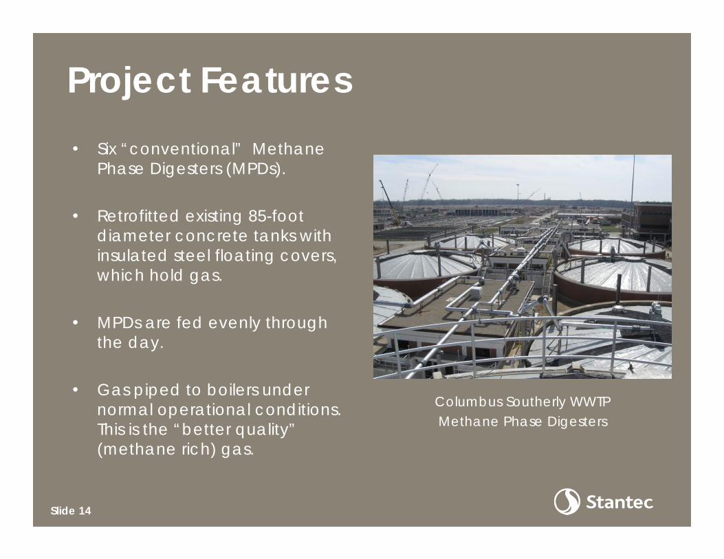
Project Features• Six “conventional” Methane
Phase Digesters (MPDs).
• Retrofitted existing 85-foot diameter concrete tanks with insulated steel floating covers, which hold gas.
• MPDs are fed evenly through the day.
• Gas piped to boilers under normal operational conditions. This is the “better quality” (methane rich) gas.
Columbus Southerly WWTP Methane Phase Digesters
Slide 14

Project Features
• Vaughn Rotamix pumped mixing system for Feedwells, APDs, and MPDs.
• A Computational Fluid Dynamics (CFD) study was conducted by vendor during design to determine mixing nozzle placement.
• Mixing pumps are located next to the tanks in the tunnel area. No moving parts are within the tanks themselves.
Columbus Southerly WWTP Mixing System Piping
Slide 15

Project Features• Sludge heated by
hydrothermal using direct steam injectors.
• Steam supplied from boilers, which are fueled by digester gas.
• Main (“raw”) steam injectors located upstream of APDs.
• Additional steam injectors are located on the MPD mixing system to maintain constant temperature in MPDs.
Columbus Southerly WWTP Steam Injector
Slide 16
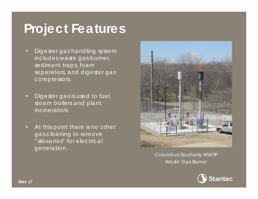
Project Features• Digester gas handling system
includes waste gas burner, sediment traps, foam separators, and digester gas compressors.
• Digester gas is used to fuel steam boilers and plant incinerators.
• At this point there is no other gas cleaning to remove “siloxanes” for electrical generation.
Columbus Southerly WWTP Waste Gas Burner
Slide 17

Distribution of Primary Solids Delivered into Columbus Southerly WWTP. Values are in GPD at 5% Total Solids.
Slide 18
Process Schematic Diagram

Digester Foaming Begins• The Methane
Phase Digesters have foamed periodically since the system was started in 2009.
• Foam builds up in the annular space between the digester covers and the tank wall.
• During severe foaming episodes, foam spills over the tank walls.
Columbus Southerly WWTP Residue from Foaming Episode
Slide 19

Importance of Foam Control
• Foam is a byproduct of the surface chemistry of how gas, liquid, and solids interact in solution.
• There have been many explanations given as to the cause of foam and is not well understood.
• All agree that the potential for foaming robs a system of capacity, which in turn hinders the production of methane gas.
Slide 20

Importance of Foam Control
• Can all foaming be eliminated from a system? The answer: probably not.
• But, performance can be improved to optimize the system.
• Foaming incidences can be better predicted, mitigated and reduced.
Slide 21
Digester Optimization Study
• Commissioned by the City of Columbus in 2010.
• Purpose was to determine the likely cause or causes of foaming and to make recommendations.
• Initial focus was on improving the function of the Acid Phase Digesters.
Slide 22

• Sludge samples were taken periodically from October 2010 through October 2011.
• Initial testing parameters on the system included percent total solids, percent volatile solids, pH, volatile fatty acids, alkalinity, oxygen reduction potential, and temperature.
• These tests were performed to help eliminate some possible foaming causes.
• The results did not pinpoint the exact cause (or causes).
Slide 23
Digester Optimization Study

Possible Causes of Foaming The following possible causes for foaming were considered for initial evaluation:
• Excessive mixing• pH• Toxicants• Sludge temperature• Latent toxicity from boiler chemicals• Gas pressure• Volatile Fatty Acids concentration• Intermittent feeding• Filaments (Nocardia and Microthirx Parvacella)• Short circuiting• Inadequate pre-mixing of sludges• Volatile loading variation
Slide 24

Possible Causes of Foaming
Slide 25
POSSIBLE ISSUE COMMENTS DETERMINATIONExcessive Mixing Could contribute to frothing. One mixing pump impeller was changed out to reduce
the applied mixing energy with no difference noted.
Sludge Temperature Variations >1º C per day can upset the process.
While problems were noted during start up, temperature fluctuations did not appear.
Intermittent or Slug Feeding Interruptions to the feed can lead to foaming.
The “most open valve” fed system feeds all tanks evenly.
Filaments: Nocardia and Microthirx Pavacella
Hydrophobic composition of filaments may alter surface chemistry at foam interface.
Possible minor or contributing factor.
Volatile Solids Loading Variation
Recommended daily variation in volatile solids load (organic load) stay within ± 5-10 percent of the previous day’s loadings.
Daily Variations in volatile solids loading are noted to exceed 30% on a daily basis. This is far outside of the desired range of 5-10%. A strong correlation was discovered between high volatile solids variation and foaming events.
Short-Circuiting Short-circuiting of sludge within the digester by inadequate mixing or poor pipe placement.
There are no obvious flaws in the piping arrangement to support this as a likely cause.

• Previous papers at WEFTEC including WERF included much focus on filamentous bacteria in the activated sludge process.
• The emphasis of our study ultimately settled on a different possible cause: variability of volatile solids loading.
• Most of this loading variation can be attributed to wet weather activity in the sewer system.
Simple Foam
Anaerobic Digester Foaming
Slide 26

Wet Weather Generates Different Solids Loadings for Treatment
This USEPA illustration shows a combined sewer system in dry and wet weather. Many WWTPs in the United States and Canada experience wet weather challenges.
Slide 27

Primary Sludge Daily Flows

Primary Solids Loading
• Data from previous figure is from 2006 – 2012.
• Solids fed to digestion are pre-thickened to 5% TS.
• The 50% percentile pumping rate was 186,784 GPD.
• The 90th percentile flow rate was 365,621 GPD.
• Elevated values may occur over several weeks.
Slide 29

• High values occur through scour of interceptor sewers during wet weather conditions.
• The City has had two OEPA Consent Orders and has spent significant resources on wet weather compliance.
• Wet weather compliance has impacted solids generation.
• During peak wet weather periods, TPS is sent directly to dewatering.
Slide 30
Primary Solids Loading
• While TPS is variable, biological sludge wasted from the activated sludge system varies little.
• Previous studies on the subject of foaming have indicated that the percentage of TWAS should be maintained at < 40% of the total amount.
• We recommend maintaining Volatile Solids (VS) loading within 5-10% per day.
Slide 31
Primary Solids Loading

Daily Variability of TPS Flow during January 2011. This is based on 5% TS.
Slide 32
Primary Solids Loading

Loading Summary Points
• As was mentioned, the end point objective would be to maintain a relatively even feed based on the previously daily loading
• At the present time, this is difficult to accomplish.
• Other than feed wells, there is little solids storage ahead of digestion.
• Operationally, the plant attempts to hold back solids in the primary clarifiers and gravity thickener.
Slide 33

Solution Considerations
The solution must recognize the following:
• Ohio’s changing wet weather patterns and climate change may be a factor.
• It is unlikely that the City will reduce or eliminate all wet weather flows in its collection system.
• Unlike many other WWTPs, Columbus Southerly WWTP does not experience significant amounts of filamentous bacteria.
Slide 34

Major Elements:
• Implement a load leveling system to handle TPS.
• Implement a process control strategy to maintain a feed rate of TPS within the desired range.
• Use a de-foaming agent to help combat potential foaming outbreaks.
Slide 35
Solution Considerations
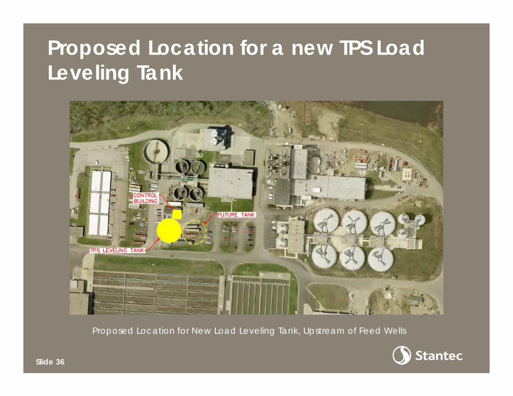
Proposed Location for a new TPS Load Leveling Tank
Proposed Location for New Load Leveling Tank, Upstream of Feed Wells
Slide 36

Schematic Diagram of Load Leveling System
Concept Diagram of Potential Load Leveling System
Slide 37

Questions?
Presented by:
Dale Kocarek, Stantec (614) 486-4383
Jeff Hall, City of Columbus (614) 645-3248