Embed Size (px)
Citation preview
Order code: EQLED038
Colour Raider Uplighter Pack
User Manual
www.prolight.co.uk Colour Raider Uplighter Pack User Manual 2
Safety advice
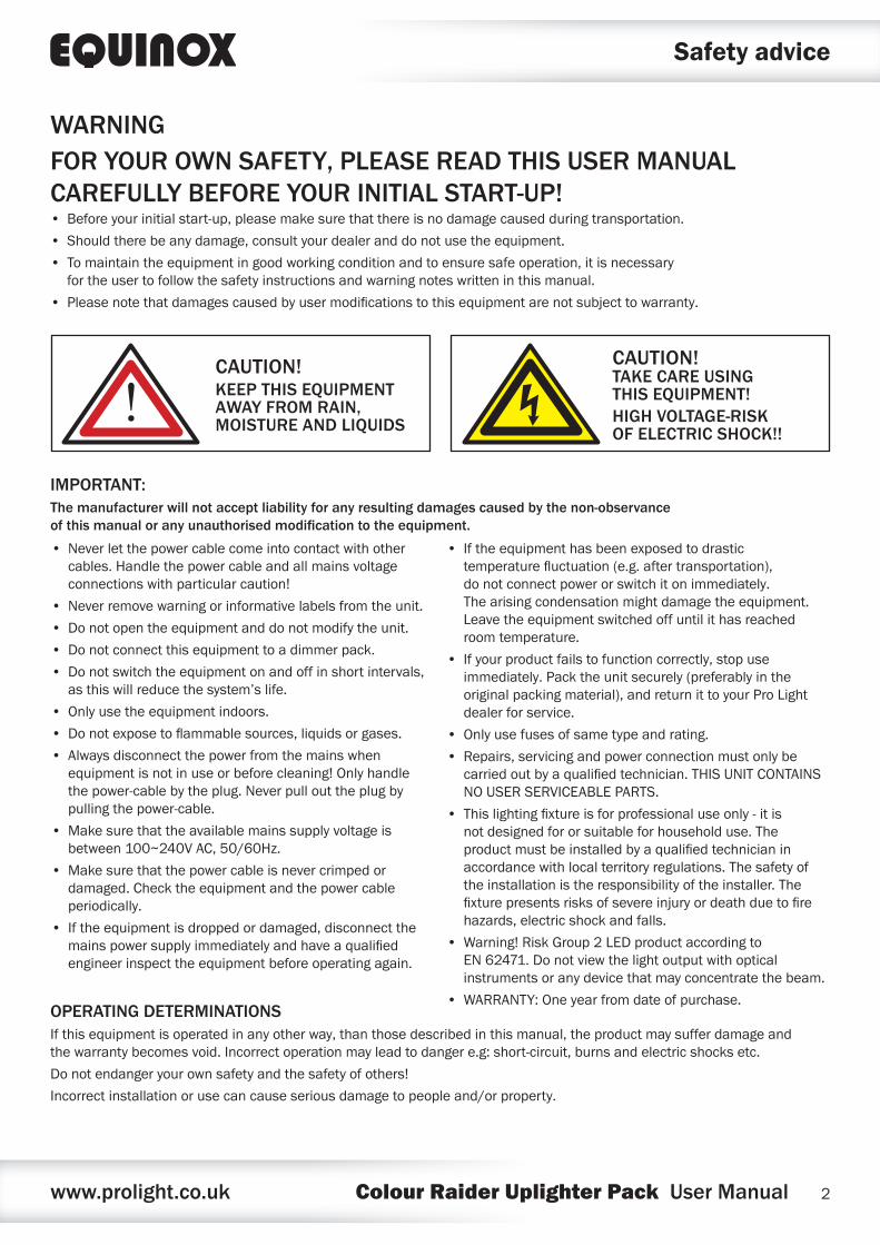
WARNINGFOR YOUR OWN SAFETY, PLEASE READ THIS USER MANUAL CAREFULLY BEFORE YOUR INITIAL START-UP!• Before your initial start-up, please make sure that there is no damage caused during transportation.
• Should there be any damage, consult your dealer and do not use the equipment.
• To maintain the equipment in good working condition and to ensure safe operation, it is necessary for the user to follow the safety instructions and warning notes written in this manual.
• Please note that damages caused by user modifications to this equipment are not subject to warranty.
IMPORTANT:The manufacturer will not accept liability for any resulting damages caused by the non-observance of this manual or any unauthorised modification to the equipment.
OPERATING DETERMINATIONSIf this equipment is operated in any other way, than those described in this manual, the product may suffer damage and the warranty becomes void. Incorrect operation may lead to danger e.g: short-circuit, burns and electric shocks etc.
Do not endanger your own safety and the safety of others!
Incorrect installation or use can cause serious damage to people and/or property.
CAUTION!KEEP THIS EQUIPMENT AWAY FROM RAIN, MOISTURE AND LIQUIDS
CAUTION! TAKE CARE USING THIS EQUIPMENT!HIGH VOLTAGE-RISK OF ELECTRIC SHOCK!!
• Never let the power cable come into contact with other cables. Handle the power cable and all mains voltage connections with particular caution!
• Never remove warning or informative labels from the unit.
• Do not open the equipment and do not modify the unit.
• Do not connect this equipment to a dimmer pack.
• Do not switch the equipment on and off in short intervals, as this will reduce the system’s life.
• Only use the equipment indoors.
• Do not expose to flammable sources, liquids or gases.
• Always disconnect the power from the mains when equipment is not in use or before cleaning! Only handle the power-cable by the plug. Never pull out the plug by pulling the power-cable.
• Make sure that the available mains supply voltage is between 100~240V AC, 50/60Hz.
• Make sure that the power cable is never crimped or damaged. Check the equipment and the power cable periodically.
• If the equipment is dropped or damaged, disconnect the mains power supply immediately and have a qualified engineer inspect the equipment before operating again.
• If the equipment has been exposed to drastic temperature fluctuation (e.g. after transportation), do not connect power or switch it on immediately. The arising condensation might damage the equipment. Leave the equipment switched off until it has reached room temperature.
• If your product fails to function correctly, stop use immediately. Pack the unit securely (preferably in the original packing material), and return it to your Pro Light dealer for service.
• Only use fuses of same type and rating.
• Repairs, servicing and power connection must only be carried out by a qualified technician. THIS UNIT CONTAINS NO USER SERVICEABLE PARTS.
• This lighting fixture is for professional use only - it is not designed for or suitable for household use. The product must be installed by a qualified technician in accordance with local territory regulations. The safety of the installation is the responsibility of the installer. The fixture presents risks of severe injury or death due to fire hazards, electric shock and falls.
• Warning! Risk Group 2 LED product according to EN 62471. Do not view the light output with optical instruments or any device that may concentrate the beam.
• WARRANTY: One year from date of purchase.
www.prolight.co.uk Colour Raider Uplighter Pack User Manual 3
Product overview & technical specifications
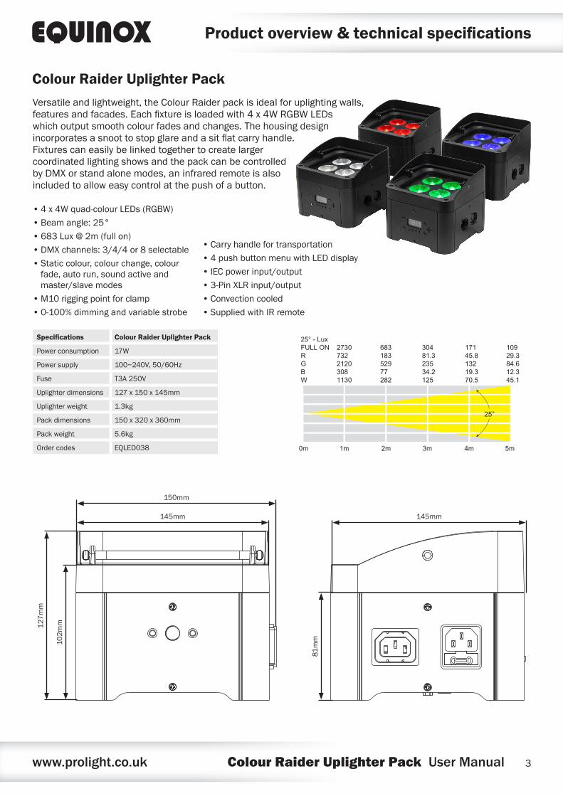
Versatile and lightweight, the Colour Raider pack is ideal for uplighting walls, features and facades. Each fixture is loaded with 4 x 4W RGBW LEDs which output smooth colour fades and changes. The housing design incorporates a snoot to stop glare and a sit flat carry handle. Fixtures can easily be linked together to create larger coordinated lighting shows and the pack can be controlled by DMX or stand alone modes, an infrared remote is also included to allow easy control at the push of a button.
• 4 x 4W quad-colour LEDs (RGBW)
• Beam angle: 25°
• 683 Lux @ 2m (full on)
• DMX channels: 3/4/4 or 8 selectable
• Static colour, colour change, colour fade, auto run, sound active and master/slave modes
• M10 rigging point for clamp
• 0-100% dimming and variable strobe
• Carry handle for transportation
• 4 push button menu with LED display
• IEC power input/output
• 3-Pin XLR input/output
• Convection cooled
• Supplied with IR remote
Colour Raider Uplighter Pack
Specifications Colour Raider Uplighter Pack
Power consumption 17W
Power supply 100~240V, 50/60Hz
Fuse T3A 250V
Uplighter dimensions 127 x 150 x 145mm
Uplighter weight 1.3kg
Pack dimensions 150 x 320 x 360mm
Pack weight 5.6kg
Order codes EQLED038 0m 1m 2m 3m 4m 5m
25° - LuxFULL ONRGBW
273073221203081130
68318352977282
30481.323534.2125
25°
17145.813219.370.5
10929.384.612.345.1
145mm
150mm
145mm
102
mm
81m
m
127
mm
www.prolight.co.uk Colour Raider Uplighter Pack User Manual 4
Product overview & technical specifications
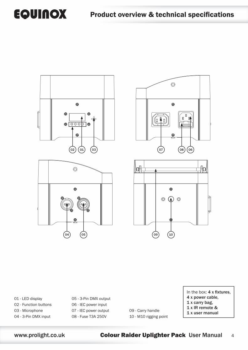
01 - LED display
02 - Function buttons
03 - Microphone
04 - 3-Pin DMX input
05 - 3-Pin DMX output
06 - IEC power input
07 - IEC power output
08 - Fuse T3A 250V
09 - Carry handle
10 - M10 rigging point
07
10090504
02 01 03 08 06
In the box: 4 x fixtures, 4 x power cable, 1 x carry bag, 1 x IR remote & 1 x user manual
www.prolight.co.uk Colour Raider Uplighter Pack User Manual 5
Operating instructions
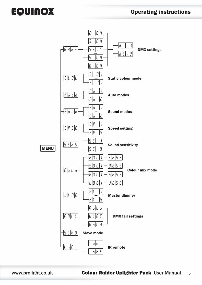
MENU
d 1
d 5 1 2DMX settingsA d d r
8 C H
4 C H
4 - 1 C
3 C H
2 C H
DMX fail settingsF A I L
H o L d
b L A C
A u t o
S 0 1
S 1 7S t @ t Static colour mode
A u 1
A u 2A u t o Auto modes
S o 1
S o 2S o u n Sound modes
S P 1
S P 9S P E E Speed setting
d I 1
d I 9d I N N Master dimmer
S E 1
S E 9S E n S Sound sensitivity
C o L o
r 0 0 1
g 0 0 1
r 2 5 5
g 2 5 5
b 0 0 1
U 0 0 1
b 2 5 5
U 2 5 5
Colour mix mode
o n
o F FI n F r IR remote
S L A V Slave mode
www.prolight.co.uk Colour Raider Uplighter Pack User Manual 6
Operating instructions
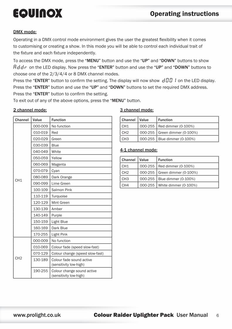
DMX mode:
Operating in a DMX control mode environment gives the user the greatest flexibility when it comes to customising or creating a show. In this mode you will be able to control each individual trait of the fixture and each fixture independently.
To access the DMX mode, press the “MENU” button and use the “UP” and “DOWN” buttons to show Addr on the LED display. Now press the “ENTER” button and use the “UP” and “DOWN” buttons to choose one of the 2/3/4/4 or 8 DMX channel modes. Press the “ENTER” button to confirm the setting. The display will now show d001 on the LED display. Press the “ENTER” button and use the “UP” and “DOWN” buttons to set the required DMX address. Press the “ENTER” button to confirm the setting. To exit out of any of the above options, press the “MENU” button.
2 channel mode:
Channel Value Function
CH1
000-009 No function
010-019 Red
020-029 Green
030-039 Blue
040-049 White
050-059 Yellow
060-069 Magenta
070-079 Cyan
080-089 Dark Orange
090-099 Lime Green
100-109 Salmon Pink
110-119 Turquoise
120-129 Mint Green
130-139 Amber
140-149 Purple
150-159 Light Blue
160-169 Dark Blue
170-255 Light Pink
CH2
000-009 No function
010-069 Colour fade (speed slow-fast)
070-129 Colour change (speed slow-fast)
130-189 Colour fade sound active (sensitivity low-high)
190-255 Colour change sound active (sensitivity low-high)
3 channel mode:
Channel Value Function
CH1 000-255 Red dimmer (0-100%)
CH2 000-255 Green dimmer (0-100%)
CH3 000-255 Blue dimmer (0-100%)
4-1 channel mode:
Channel Value Function
CH1 000-255 Red dimmer (0-100%)
CH2 000-255 Green dimmer (0-100%)
CH3 000-255 Blue dimmer (0-100%)
CH4 000-255 White dimmer (0-100%)
www.prolight.co.uk Colour Raider Uplighter Pack User Manual 7
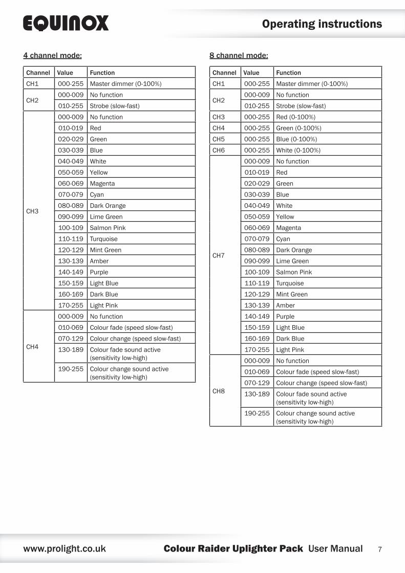
8 channel mode:
Channel Value Function
CH1 000-255 Master dimmer (0-100%)
CH2000-009 No function
010-255 Strobe (slow-fast)
CH3 000-255 Red (0-100%)
CH4 000-255 Green (0-100%)
CH5 000-255 Blue (0-100%)
CH6 000-255 White (0-100%)
CH7
000-009 No function
010-019 Red
020-029 Green
030-039 Blue
040-049 White
050-059 Yellow
060-069 Magenta
070-079 Cyan
080-089 Dark Orange
090-099 Lime Green
100-109 Salmon Pink
110-119 Turquoise
120-129 Mint Green
130-139 Amber
140-149 Purple
150-159 Light Blue
160-169 Dark Blue
170-255 Light Pink
CH8
000-009 No function
010-069 Colour fade (speed slow-fast)
070-129 Colour change (speed slow-fast)
130-189 Colour fade sound active (sensitivity low-high)
190-255 Colour change sound active (sensitivity low-high)
4 channel mode:
Channel Value Function
CH1 000-255 Master dimmer (0-100%)
CH2000-009 No function
010-255 Strobe (slow-fast)
CH3
000-009 No function
010-019 Red
020-029 Green
030-039 Blue
040-049 White
050-059 Yellow
060-069 Magenta
070-079 Cyan
080-089 Dark Orange
090-099 Lime Green
100-109 Salmon Pink
110-119 Turquoise
120-129 Mint Green
130-139 Amber
140-149 Purple
150-159 Light Blue
160-169 Dark Blue
170-255 Light Pink
CH4
000-009 No function
010-069 Colour fade (speed slow-fast)
070-129 Colour change (speed slow-fast)
130-189 Colour fade sound active (sensitivity low-high)
190-255 Colour change sound active (sensitivity low-high)
Operating instructions
www.prolight.co.uk Colour Raider Uplighter Pack User Manual 8
Operating instructions
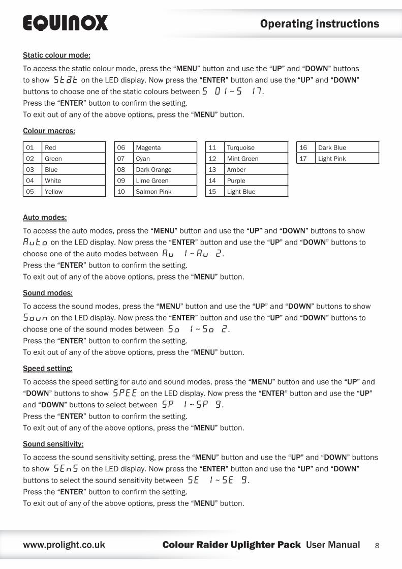
Static colour mode:
To access the static colour mode, press the “MENU” button and use the “UP” and “DOWN” buttons to show St@t on the LED display. Now press the “ENTER” button and use the “UP” and “DOWN” buttons to choose one of the static colours between S 01 ~ S 17. Press the “ENTER” button to confirm the setting. To exit out of any of the above options, press the “MENU” button.
Auto modes:
To access the auto modes, press the “MENU” button and use the “UP” and “DOWN” buttons to show Auto on the LED display. Now press the “ENTER” button and use the “UP” and “DOWN” buttons to choose one of the auto modes between Au 1 ~ Au 2. Press the “ENTER” button to confirm the setting. To exit out of any of the above options, press the “MENU” button.
Sound modes:
To access the sound modes, press the “MENU” button and use the “UP” and “DOWN” buttons to show Soun on the LED display. Now press the “ENTER” button and use the “UP” and “DOWN” buttons to choose one of the sound modes between So 1 ~ So 2. Press the “ENTER” button to confirm the setting. To exit out of any of the above options, press the “MENU” button.
Speed setting:
To access the speed setting for auto and sound modes, press the “MENU” button and use the “UP” and “DOWN” buttons to show SPEE on the LED display. Now press the “ENTER” button and use the “UP” and “DOWN” buttons to select between SP 1 ~ SP 9. Press the “ENTER” button to confirm the setting. To exit out of any of the above options, press the “MENU” button.
Sound sensitivity:
To access the sound sensitivity setting, press the “MENU” button and use the “UP” and “DOWN” buttons to show SEns on the LED display. Now press the “ENTER” button and use the “UP” and “DOWN” buttons to select the sound sensitivity between SE 1 ~ SE 9. Press the “ENTER” button to confirm the setting. To exit out of any of the above options, press the “MENU” button.
Colour macros:
01 Red
02 Green
03 Blue
04 White
05 Yellow
06 Magenta
07 Cyan
08 Dark Orange
09 Lime Green
10 Salmon Pink
11 Turquoise
12 Mint Green
13 Amber
14 Purple
15 Light Blue
16 Dark Blue
17 Light Pink
www.prolight.co.uk Colour Raider Uplighter Pack User Manual 9
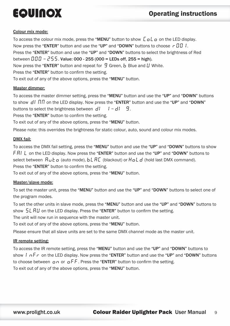
Colour mix mode:
To access the colour mix mode, press the “MENU” button to show CoLo on the LED display. Now press the “ENTER” button and use the “UP” and “DOWN” buttons to choose r001. Press the “ENTER” button and use the “UP” and “DOWN” buttons to select the brightness of Red between 000 ~ 255. Value: 000 - 255 (000 = LEDs off, 255 = high). Now press the “ENTER” button and repeat for g Green, b Blue and U White. Press the “ENTER” button to confirm the setting. To exit out of any of the above options, press the “MENU” button.
Master dimmer:
To access the master dimmer setting, press the “MENU” button and use the “UP” and “DOWN” buttons to show dINN on the LED display. Now press the “ENTER” button and use the “UP” and “DOWN” buttons to select the brightness between dI 1 ~ dI 9. Press the “ENTER” button to confirm the setting. To exit out of any of the above options, press the “MENU” button.
Please note: this overrides the brightness for static colour, auto, sound and colour mix modes.
DMX fail:
To access the DMX fail setting, press the “MENU” button and use the “UP” and “DOWN” buttons to show FAIL on the LED display. Now press the “ENTER” button and use the “UP” and “DOWN” buttons to select between Auto (auto mode), bLAC (blackout) or HoLd (hold last DMX command). Press the “ENTER” button to confirm the setting. To exit out of any of the above options, press the “MENU” button.
Master/slave mode:
To set the master unit, press the “MENU” button and use the “UP” and “DOWN” buttons to select one of the program modes.
To set the other units in slave mode, press the “MENU” button and use the “UP” and “DOWN” buttons to show SLAV on the LED display. Press the “ENTER” button to confirm the setting. The unit will now run in sequence with the master unit. To exit out of any of the above options, press the “MENU” button.
Please ensure that all slave units are set to the same DMX channel mode as the master unit.
IR remote setting:
To access the IR remote setting, press the “MENU” button and use the “UP” and “DOWN” buttons to show InFr on the LED display. Now press the “ENTER” button and use the “UP” and “DOWN” buttons to choose between on or ofF. Press the “ENTER” button to confirm the setting. To exit out of any of the above options, press the “MENU” button.
Operating instructions
www.prolight.co.uk Colour Raider Uplighter Pack User Manual 10
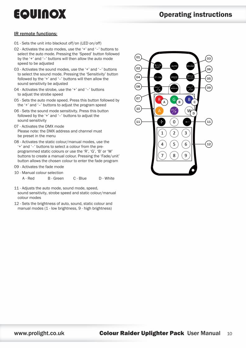
01 - Sets the unit into blackout off/on (LED on/off)
02 - Activates the auto modes, use the ‘+’ and ‘–’ buttons to select the auto mode. Pressing the ‘Speed’ button followed by the ‘+’ and ‘–’ buttons will then allow the auto mode speed to be adjusted
03 - Activates the sound modes, use the ‘+’ and ‘–’ buttons to select the sound mode. Pressing the ‘Sensitivity’ button followed by the ‘+’ and ‘–’ buttons will then allow the sound sensitivity be adjusted
04 - Activates the strobe, use the ‘+’ and ‘–’ buttons to adjust the strobe speed
05 - Sets the auto mode speed. Press this button followed by the ‘+’ and ‘–’ buttons to adjust the program speed
06 - Sets the sound mode sensitivity. Press this button followed by the ‘+’ and ‘–’ buttons to adjust the sound sensitivity
07 - Activates the DMX mode Please note: the DMX address and channel must be preset in the menu
08 - Activates the static colour/manual modes, use the ‘+’ and ‘–’ buttons to select a colour from the pre-programmed static colours or use the ‘R’, ‘G’, ‘B’ or ‘W’ buttons to create a manual colour. Pressing the ‘Fade/unit’ button allows the chosen colour to enter the fade program
09 - Activates the fade mode
10 - Manual colour selection
11 - Adjusts the auto mode, sound mode, speed, sound sensitivity, strobe speed and static colour/manual colour modes
12 - Sets the brightness of auto, sound, static colour and manual modes (1 - low brightness, 9 - high brightness)
Operating instructions
BLACKOUT AUTO SOUND
STROBE SPEED SENSI-TIVITY
%DMX
MANUALFADE
UNIT
R BG
A WPUV
0
31 2
4 5 6
8 9
+
7
07
01
02
04
08
10
11
05
09
03
06
12
11
A B C
D
IR remote functions:
A - Red B - Green C - Blue D - White
www.prolight.co.uk Colour Raider Uplighter Pack User Manual 11
Setting the DMX address:
The DMX mode enables the use of a universal DMX controller. Each fixture requires a “start address” from 1- 512. A fixture requiring one or more channels for control begins to read the data on the channel indicated by the start address. For example, a fixture that occupies or uses 7 channels of DMX and was addressed to start on DMX channel 100, would read data from channels: 100, 101, 102, 103, 104, 105 and 106. Choose a start address so that the channels used do not overlap. E.g. the next unit in the chain starts at 107.
DMX 512:
DMX (Digital Multiplex) is a universal protocol used as a form of communication between intelligent fixtures and controllers. A DMX controller sends DMX data instructions form the controller to the fixture. DMX data is sent as serial data that travels from fixture to fixture via the DATA “IN” and DATA “OUT” XLR terminals located on all DMX fixtures (most controllers only have a data “out” terminal).
DMX linking:
DMX is a language allowing all makes and models of different manufactures to be linked together and operate from a single controller, as long as all fixtures and the controller are DMX compliant. To ensure proper DMX data transmission, when using several DMX fixtures try to use the shortest cable path possible. The order in which fixtures are connected in a DMX line does not influence the DMX addressing. For example; a fixture assigned to a DMX address of 1 may be placed anywhere in a DMX line, at the beginning, at the end, or anywhere in the middle. When a fixture is assigned a DMX address of 1, the DMX controller knows to send DATA assigned to address 1 to that unit, no matter where it is located in the DMX chain.
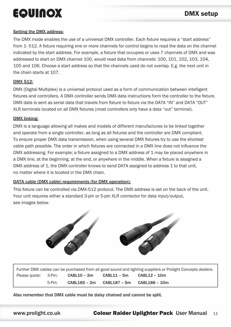
DATA cable (DMX cable) requirements (for DMX operation):
This fixture can be controlled via DMX-512 protocol. The DMX address is set on the back of the unit. Your unit requires either a standard 3-pin or 5-pin XLR connector for data input/output, see images below.
Also remember that DMX cable must be daisy chained and cannot be split.
DMX setup
Further DMX cables can be purchased from all good sound and lighting suppliers or Prolight Concepts dealers.Please quote: CABL10 – 2m CABL11 – 5m CABL12 – 10m3-Pin:
CABL185 – 2m CABL187 – 5m CABL188 – 10m5-Pin:
www.prolight.co.uk Colour Raider Uplighter Pack User Manual 12
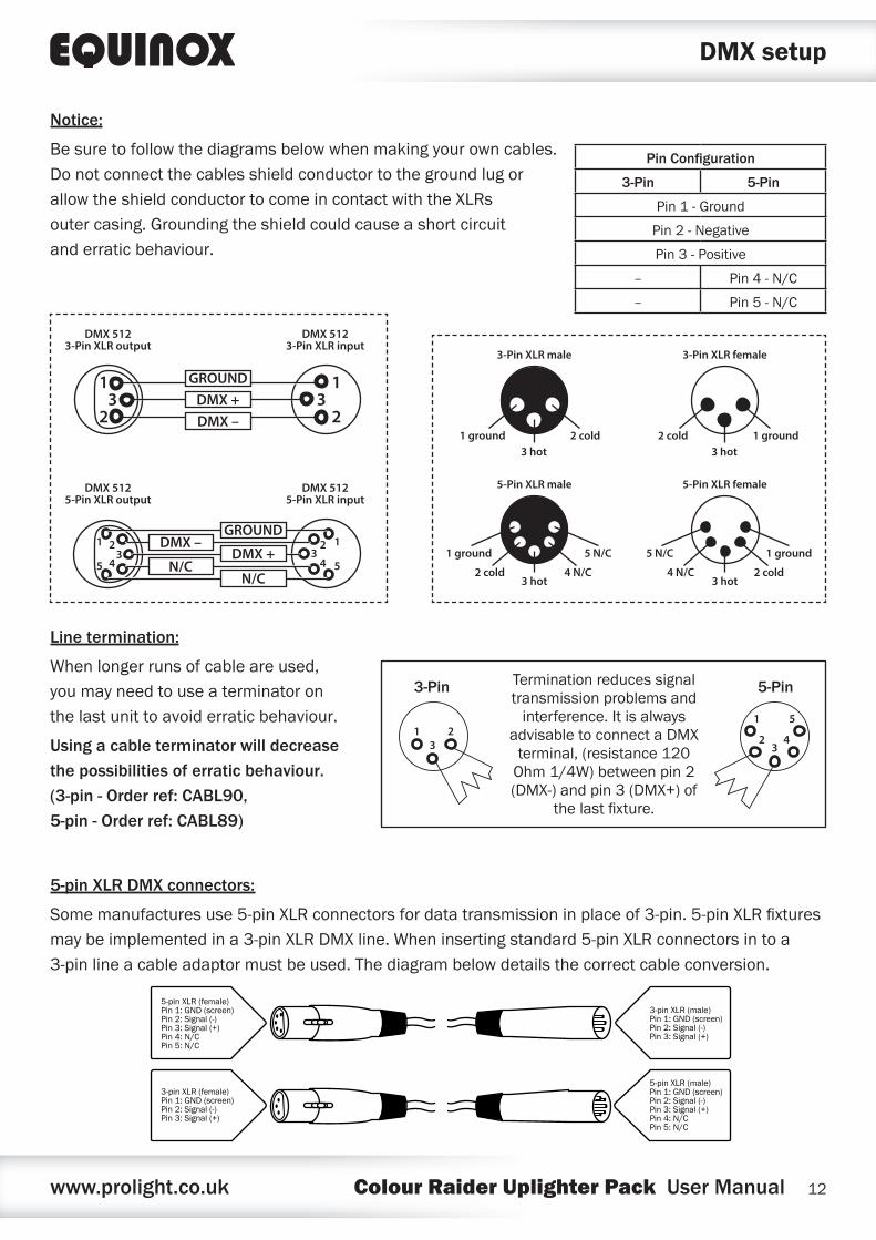
Notice:
Be sure to follow the diagrams below when making your own cables. Do not connect the cables shield conductor to the ground lug or allow the shield conductor to come in contact with the XLRs outer casing. Grounding the shield could cause a short circuit and erratic behaviour.
Line termination:
When longer runs of cable are used, you may need to use a terminator on the last unit to avoid erratic behaviour.
Using a cable terminator will decrease the possibilities of erratic behaviour. (3-pin - Order ref: CABL90, 5-pin - Order ref: CABL89)
5-pin XLR DMX connectors:
Some manufactures use 5-pin XLR connectors for data transmission in place of 3-pin. 5-pin XLR fixtures may be implemented in a 3-pin XLR DMX line. When inserting standard 5-pin XLR connectors in to a 3-pin line a cable adaptor must be used. The diagram below details the correct cable conversion.
5-pin XLR (female)Pin 1: GND (screen)Pin 2: Signal (-)Pin 3: Signal (+)Pin 4: N/CPin 5: N/C
3-pin XLR (female)Pin 1: GND (screen)Pin 2: Signal (-)Pin 3: Signal (+)
3-pin XLR (male)Pin 1: GND (screen)Pin 2: Signal (-)Pin 3: Signal (+)
5-pin XLR (male)Pin 1: GND (screen)Pin 2: Signal (-)Pin 3: Signal (+)Pin 4: N/CPin 5: N/C
DMX setup
Termination reduces signal transmission problems and
interference. It is always advisable to connect a DMX
terminal, (resistance 120 Ohm 1/4W) between pin 2 (DMX-) and pin 3 (DMX+) of
the last fixture.
5-Pin
1
2 4
5
3
3-Pin
1 23
Pin Configuration
3-Pin 5-Pin
Pin 1 - Ground
Pin 2 - Negative
Pin 3 - Positive
– Pin 4 - N/C
– Pin 5 - N/C
1
23
1
23
DMX 5123-Pin XLR output
DMX 5123-Pin XLR input
GROUNDDMX +DMX –
DMX 5125-Pin XLR output
DMX 5125-Pin XLR input
12
4 53
1 2
453
GROUND
N/C
DMX –
N/CDMX +
1 ground3 hot
2 cold
3-Pin XLR male 3-Pin XLR female
2 cold3 hot
1 ground
2 cold
1 ground 5 N/C
3 hot4 N/C
5-Pin XLR male 5-Pin XLR female
4 N/C
5 N/C 1 ground
3 hot2 cold
www.prolight.co.uk Colour Raider Uplighter Pack User Manual 13
Multiple fixture power linking
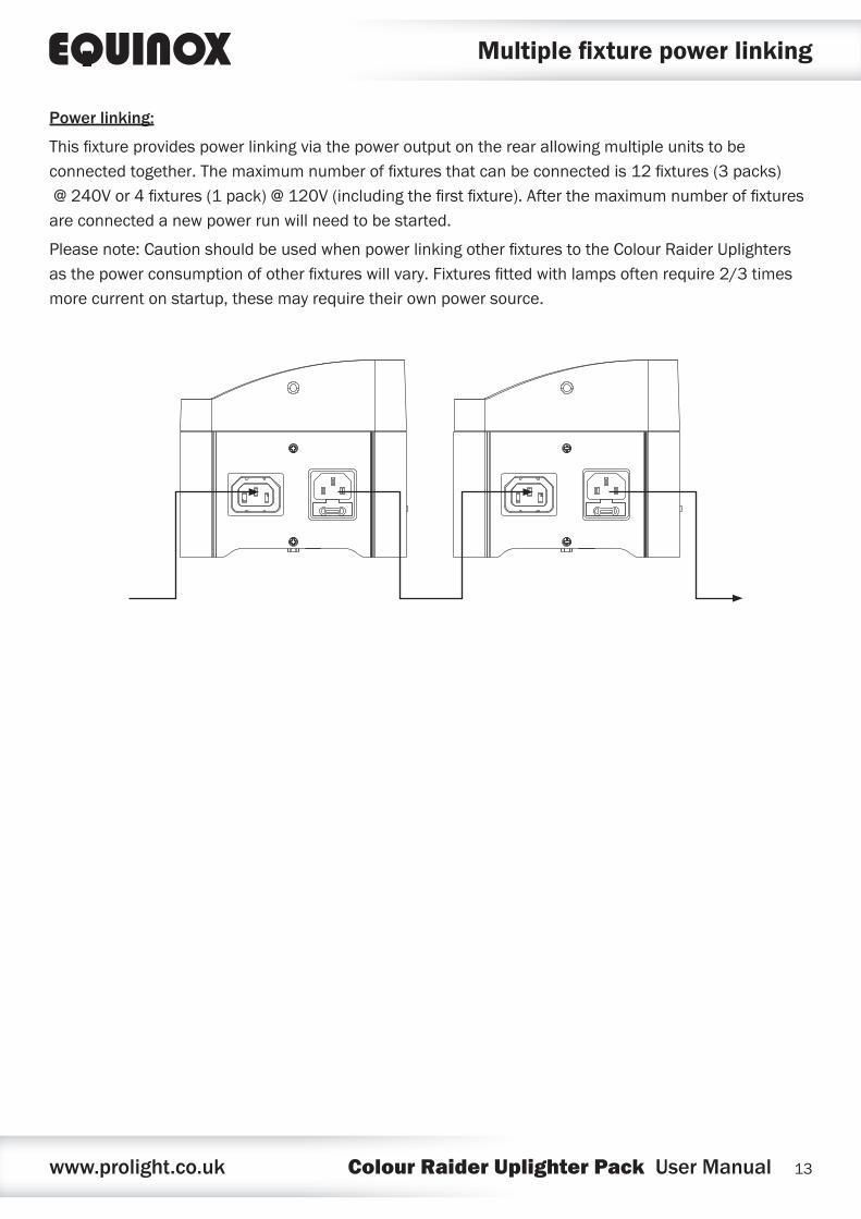
Power linking:
This fixture provides power linking via the power output on the rear allowing multiple units to be connected together. The maximum number of fixtures that can be connected is 12 fixtures (3 packs) @ 240V or 4 fixtures (1 pack) @ 120V (including the first fixture). After the maximum number of fixtures are connected a new power run will need to be started.
Please note: Caution should be used when power linking other fixtures to the Colour Raider Uplighters as the power consumption of other fixtures will vary. Fixtures fitted with lamps often require 2/3 times more current on startup, these may require their own power source.

www.prolight.co.uk Colour Raider Uplighter Pack User Manual 14
WEEE notice
Correct Disposal of this Product (Waste Electrical & Electronic Equipment)
(Applicable in the European Union and other European countries with separate collection systems)
This marking shown on the product or its literature, indicates that it should not be disposed of with other household wastes at the end of its working life. To prevent possible harm to the environment or human health from uncontrolled waste disposal, please separate this from other types of wastes and recycle it responsibly to promote the sustainable reuse of material resources.
Household users should contact either the retailer where they purchased this product, or their local government office, for details of where and how they can take this item for environmentally safe recycling.
Business users should contact their supplier and check the terms and conditions of the purchase contract. This product should not be mixed with other commercial wastes for disposal.
www.prolight.co.uk Colour Raider Uplighter Pack User Manual 15

www.prolight.co.uk Colour Raider Uplighter Pack User Manual 16