Embed Size (px)
Citation preview

1
Collision in Star Topology: Case 3
A B C D
E
Collision presence signal
A and D transmitting
1
Presentation E 2
IEEE 802.3 MAC Frame Format
≥ ≥
Ethernet frame format differs that “Length” field is used for other purposes, i.e. protocol.
Figure 16.3
g. babic

2
Presentation E 3
• 10Base5: 10Mbps, coaxial (thick) cable, bus topology, — maximum segment length 500m, segments may be
connected with repeaters, up to 4 repeaters between any two stations, up to 2500m network span, and Manchester encoding
• 10Base2: 10Mbps, coaxial (thin) cable, bus, 200m segments• 10Base-T: 10Mps, UTP, star, Manchester, 100m links• 10Base-F: 10Mbps, 850 nm fiber, star, On/Off, 2000m links• 100-Mbps Ethernet (Fast Ethernet), star topology, 100m links,
200m or 400m network spans, uses full-duplex mode with twophysical links between nodes—100BASE-TX uses two STPs or Cat. 5 UTPs—100BASE-FX uses two optical fibers
• 1Gbit or 10Gbit Ethernet—10GBASE-L (long) : 1310 nm on single-mode fiber, 10 km
IEEE 802.3 Specifications
g. babic
d. xuan DataLink Layer 4
“Taking Turns” MAC protocols
channel partitioning MAC protocols:—share channel efficiently at high load—inefficient at low load: delay in channel access, 1/N
bandwidth allocated even if only 1 active node! Random access MAC protocols
—efficient at low load: single node can fully utilize channel
—high load: collision overhead“taking turns” protocols
look for best of both worlds!

3
d. xuan DataLink Layer 5
“Taking Turns” MAC protocols
Polling:• master node “invites”
slave nodes to transmit in turn
• Request to Send, Clear to Send msgs
• concerns:— polling overhead — latency— single point of failure
(master)
Token passing: control token passed from
one node to next sequentially.
token message concerns:
token overhead latency single point of failure (token)
Presentation E 6
• Small frame (token) circulates when idle
• Station waits for token
• Changes one bit in token to make it SOF for data frame
• Append rest of data frame
• Frame makes round trip and is absorbed by transmitting station
• Station then inserts new token when transmission has finished.
IEEE 802.5 Token Ring
g. babic

4
Presenation F 7
Token Ring Operation
g. babic
Presentation E 8
• Ability to expand beyond single LAN• Bridge connects two identical (or similar) LANs
— Identical protocols for physical and link layers— Minimal processing
• Router more general purpose— Interconnect various LANs and WANs
• Functioning of bridge— Read all frames transmitted on one LAN and accept those
address to any station on the other LAN— Using MAC protocol for second LAN, retransmit each
frame— Do the same the other way round
Bridges
g. babic

5
Presentation E 9
Bridge Operation
Figure 15.8
g. babic
Presentation E 10
• No modification to content or format of frame (for identical LANs)
• No encapsulation• Exact bitwise copy of frame• Minimal buffering to meet peak demand• Bridging is transparent to stations
— Appears to all stations on multiple LANs as if they are on one single LAN
• Collision does not propagate through bridge• Contains routing and address intelligence
— Must be able to tell which frames to pass— May be more than one bridge to cross
• May connect more than two LANs
Bridge Design Aspects
g. babic

6
Presentation E 11
Bridge Protocol Architecture
• IEEE 802.1D• MAC level: station address is at this level• Bridge does not need LLC layer: it is relaying MAC frames
Figure 15.9
g. babic
Presentation E 12
LANs Connected by Bridges
Alternative routes maybe possible
Figure 15.10
g. babic
7
13
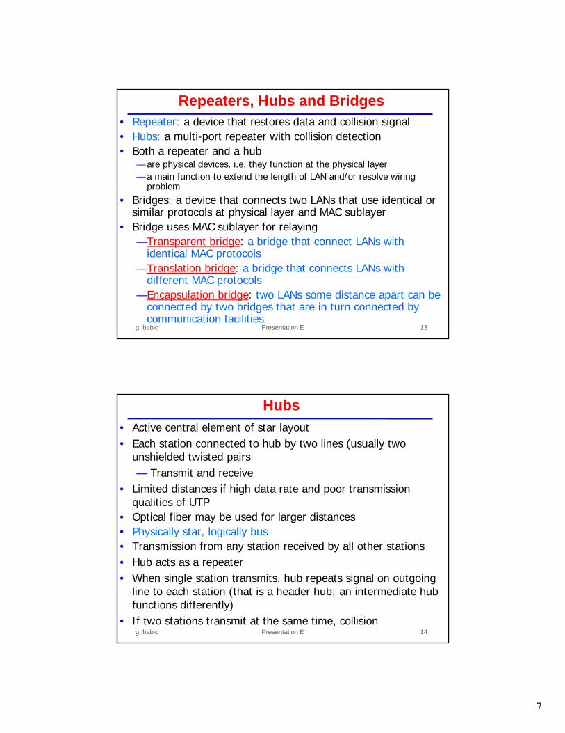
• Repeater: a device that restores data and collision signal• Hubs: a multi-port repeater with collision detection• Both a repeater and a hub
— are physical devices, i.e. they function at the physical layer — a main function to extend the length of LAN and/or resolve wiring
problem• Bridges: a device that connects two LANs that use identical or
similar protocols at physical layer and MAC sublayer• Bridge uses MAC sublayer for relaying
—Transparent bridge: a bridge that connect LANs with identical MAC protocols
—Translation bridge: a bridge that connects LANs with different MAC protocols
—Encapsulation bridge: two LANs some distance apart can be connected by two bridges that are in turn connected by communication facilities
Repeaters, Hubs and Bridges
g. babic Presentation E
Presentation E 14
• Active central element of star layout• Each station connected to hub by two lines (usually two
unshielded twisted pairs— Transmit and receive
• Limited distances if high data rate and poor transmission qualities of UTP
• Optical fiber may be used for larger distances• Physically star, logically bus• Transmission from any station received by all other stations• Hub acts as a repeater• When single station transmits, hub repeats signal on outgoing
line to each station (that is a header hub; an intermediate hub functions differently)
• If two stations transmit at the same time, collision
Hubs
g. babic

8
Presentation E 15
Shared Medium Bus and Hub
Figure 15.13
g. babic
Presentation E 16
Shared Medium Hub and Layer 2 Switch
Figure 15.13
g. babic

9
Presentation E 17
• Incoming frame from particular station switched to appropriate output line
• Relaying at MAC layer• Unused lines can switch other traffic• More than one station transmitting at a time• Multiplying capacity of LAN• No change to attached devices to convert bus LAN or hub LAN
to switched LAN, e.g. for Ethernet LAN, each device still usesEthernet MAC protocol
• Each device has dedicated capacity equal to original LAN, assuming switch has sufficient capacity to keep up with all devices
• A layer 2 switch can be thought as a multi-port bridge with each LAN having only one device; a layer 2 switch selectively forwards frames from one LAN port to another.
Layer 2 Switches
g. babic
Presentation E 18
• Store-and-forward switch— Accepts frame on input line— Buffers it briefly, — Then routes it to appropriate output line— Delay between sender and receiver— Boosts integrity of network
• Cut-through switch— Takes advantage of destination address appearing at
beginning of frame— Switch begins repeating frame onto output line as soon as
it recognizes destination address— Highest possible throughput — Risk of propagating bad frames, since switch unable to
check CRC prior to retransmission
Types of Layer 2 Switches
g. babic

10
d. xuan DataLink Layer 19
Ethernet Switches
Dedicated
Shared
Presentation E 20
• Ring topology
— Very high speed links over long distances
— Used in MANs
— Single link or repeater failure disables network
• Star topology
— Uses natural layout of wiring in building
— Best for short distances
— High data rates for small number of devices
Ring and Star Topologies Usage
g. babic

11
Presentation E 21
• Choice of topology influenced by:— Reliability— Expandability— Performance— Needs considering in context of:
• Medium• Wiring layout• Medium access control
• Choice of medium constrained by:— LAN topology— Capacity— Reliability— Types of data supported— Environmental scope
Choice of Topology and Medium
g. babic
Presentation E 22
• Used in packet radio network• When station has frame, it sends• Station listens (for maximum round trip time) plus small
increment• If frame OK and address matches receiver, send ACK• Frame may be damaged by noise or by another station
transmitting at the same time (collision) • Frame check sequence (as in HDLC) detects error• If ACK received, fine. If no ACK received, retransmit.• If no ACK after repeated transmissions, give up
• Each station has to have different retransmission time out. Why? How?
• Any overlap of frames causes collision• Max utilization 18% of channel capacity
Aloha
g. babic

12
Presentation E 23
• Time in uniform slots equal to frame transmission time
• Need central clock (or other sync mechanism)
• Transmission begins at slot boundary
• Everything else as in Aloha
• Frames either miss or overlap totally
• Max utilization 37% of channel capacity
Slotted Aloha
g. babic
Presentation E 24
• If n stations waiting to send, at the end of transmission, expected number of stations attempting to transmit is— n×P
• If n×P > 1 then on average there will be a collision• Repeated attempts to transmit almost guaranteeing more
collisions, since retries compete with new transmissions • Eventually, all stations trying to send
— Continuous collisions; zero throughput• So to void instability n×P < 1 for expected peaks of n• If heavy load expected, P small• However, as P made smaller, stations wait longer• At low loads, this gives very long delays
Values of P?
g. babic

13
Presentation E 25
• In first 10 retransmission attempts, mean value of random delay doubled
• Value then remains same for 6 further attempts• After 16 unsuccessful attempts, station gives up and
reports error• As congestion increases, stations back off by larger
amounts to reduce the probability of collision.• 1-persistent algorithm with binary exponential backoff
efficient over wide range of loads— Low loads, 1-persistence guarantees station can
seize channel once idle— High loads, at least as stable as other techniques
• Backoff algorithm gives last-in, first-out effect• Stations with few collisions transmit first
Binary Exponential Backoff
g. babic
Presentation E 26
• Traditional Ethernet half duplex• With full-duplex, station can transmit & receive simultaneously
— Two physical links between nodes: transmission and reception
• 100-Mbps Ethernet (Fast Ethernet) uses full-duplex mode, theoretical transfer rate 200 Mbps, star topology, 100m links, 200m or 400m network spans
• 100BASE-TX uses two STPs or Cat. 5 UTPs• 100BASE-FX uses two optical fibers
• 100BASE-T4 uses 4 Cat. 3 (low quality voice-grade) UTP;— Taking advantage of large installed base— Data stream split into three separate streams; Each with an
effective data rate of 33.33 Mbps
100Mbps Ethernet Specifications
g. babic
14
Presentation E 27
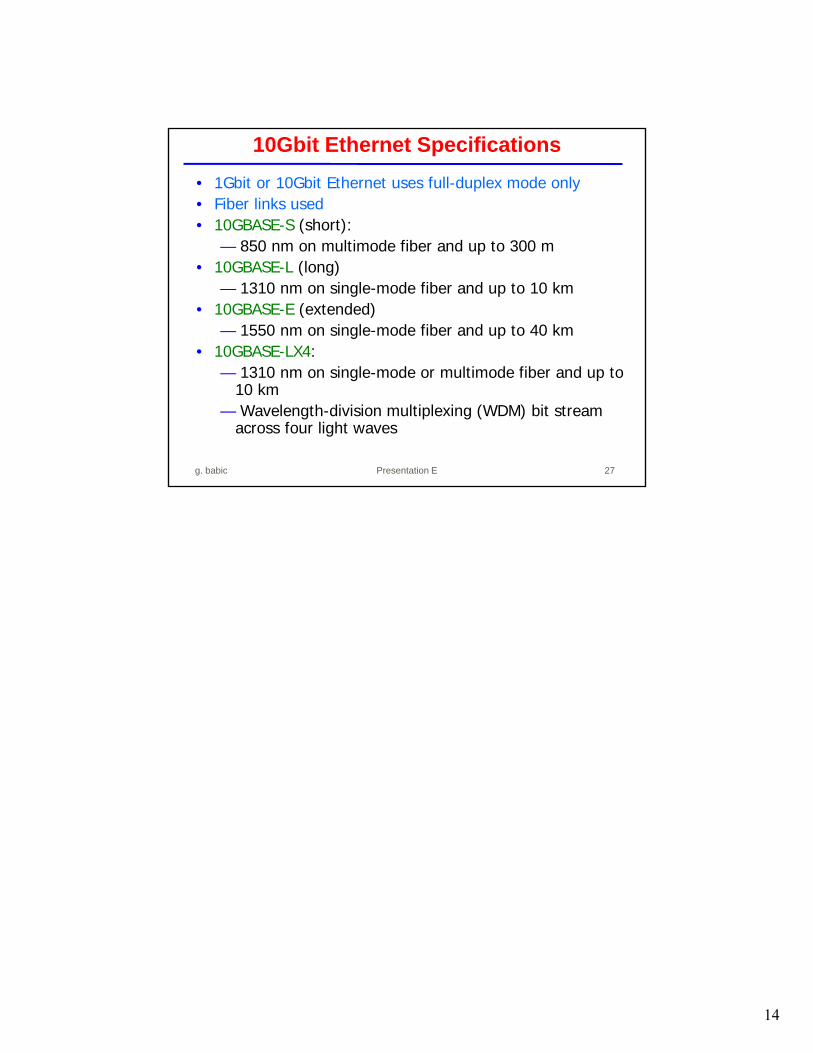
• 1Gbit or 10Gbit Ethernet uses full-duplex mode only• Fiber links used• 10GBASE-S (short):
— 850 nm on multimode fiber and up to 300 m• 10GBASE-L (long)
— 1310 nm on single-mode fiber and up to 10 km• 10GBASE-E (extended)
— 1550 nm on single-mode fiber and up to 40 km• 10GBASE-LX4:
— 1310 nm on single-mode or multimode fiber and up to 10 km
— Wavelength-division multiplexing (WDM) bit stream across four light waves
10Gbit Ethernet Specifications
g. babic