Embed Size (px)
Citation preview

College of Engineering
Department of Mechanical Engineering
Fall 2015-16
Senior Design Project Report
Pipe Inspection and Cleaning Robot
In partial fulfillment of the requirements for the Degree of Bachelor of Science in Mechanical Engineering
Team Members
Student Name Student ID 1 Abdullah Al Deghreer 201002190
2 Mohammed Alyami 201002191
3 Naif Al Mahasheer 200800447
4 Ahmed Al Shalawi 200700542
Project Advisors:
Advisor Name: Faramars Djavanroodi Co-Advisor Name: Dr. Nader Sawalhi

2
Abstract The name of our project is pipe the pipe inspecting and cleaning robot (PIAC); in a nutshell it
is a robot that will be used to clean the interior of the pipes using a brushing mechanism. One
of the critical areas of the oil and gas industry is the transport of oil and other fluids through a
network of pipes. Over time these pipes have accumulated amount of slug and other deposits;
this leads to decrease in pipeline carrying capacity, reduced reliability, loss of power due to
higher pumping pressure required and irregular flow.
In the light of the problems mentioned above we have decided to attempt to solve this
problem using our PIAC project. This will not only clean the interior of the pipe but also be
able to send live video feedback to the personnel on the ground depicting the kind of residues
found in the pipes. The robot can also be added with additional sensors to relay any other
critical information. During the course of the project we have faced multiple challenges,
which were mitigated by the team accordingly using alternatives and prior knowledge
through literature review.
There are many outcomes of this project. The first being that the set objectives of the project
are achieved which in a nutshell was to build a prototype PIAC with the mobility, cleaning
and video feedback functionality. The second outcome is that the project has worked
effectively to clean the rust that was in a sample pipe. The amount of rust removed for the
pipe was about 4 grams cleaning a surface area of 0.398 square meters the fourth outcome of
the project is that the team was able to lean many new things about the pipe cleaning industry
through the literature review and during building the prototype. The fourth and final outcome
of the project is that there is scope of improvement for the project and new engineering
standards such as ASME , NEC and IEEE can be incorporated in later builds

3
Acknowledgements
The final year project is a testament to the engineering mindset of the student and his capacity
of problem solving and applying engineering principals. However the completion of the
project can never be possible without the help of individual’s whether be it at home or in
university. We owe a lot to our advisors `Mr Nader Sawalhi and Dr Farmars Djavanroodi. It
is they who have supported our project and believed in us. With their valuable advice and
guidance we were able to make critical adjustments at specific junctures of the project.
We would also like to thank Dr Jamal Nayfeh for his excellent leadership in guiding all the
students to the path of academic excellence. Our parents our are hidden strength and have
supported us in very way. Not a leaf falls before his permission we express our gratitude to
Allah the almighty

4
1 Table of Contents
Abstract ........................................................................................................................... 2
Acknowledgements .......................................................................................................... 3
1. Introduction .............................................................................................................. 5
1.1 Project Definition ............................................................................................................ 5
1.2 Project Objectives ........................................................................................................... 5
1.3 Project Specifications ...................................................................................................... 6
1.4 Product Architecture and Components ............................................................................ 7
1.5 Applications .................................................................................................................. 10
2. Literature Review .................................................................................................... 11
2.1 Project background ....................................................................................................... 11
2.2 Previous Work ............................................................................................................... 12
2.3 Comparative Study ........................................................................................................ 18
3. System Design ......................................................................................................... 19
3.1 Design Constraints ......................................................................................................... 19
3.2 Design Methodology ................................................................................................... 21
Figures 3.4 shows the initial rejected design; Figures 3.5 and 3.6 show the final project design . 25
3.3 Product Subsystems and Components ............................................................................ 25
3.4 Implementation ............................................................................................................ 30
4. System Testing and Analysis ..................................................................................... 42
4.1 Motor RPM and torque ................................................................................................. 42
4.2 Camera video feedback test ........................................................................................... 45
4.3 Movement and cleaning ................................................................................................ 46
4.4 Overall Results, Analysis and Discussion ......................................................................... 49
5. Project Management ............................................................................................... 52
5.1 Project Plan ................................................................................................................... 52
1.2 Contribution of Team Members ..................................................................................... 54
5.3 Project Execution Monitoring ........................................................................................ 54
5.4 Challenges and Decision Making .................................................................................... 55
5.5 Project Bill of Materials and Budget ............................................................................... 56
6. Project Analysis ....................................................................................................... 57
6.1 Life-long Learning .......................................................................................................... 57
6.2 Impact of Engineering Solutions .................................................................................... 58
6.3 Contemporary Issues Addressed .................................................................................... 60
7. Conclusions and Future Recommendations .............................................................. 61
7.1 Conclusions ................................................................................................................... 61
7.2 Future Recommendations .............................................................................................. 61
8. References............................................................................................................... 63
AヮヮWミSキ┝ Aぎ PヴラェヴWゲゲ RWヮラヴデゲぐぐぐぐぐぐぐぐぐぐぐぐぐぐぐぐぐぐぐぐぐぐぐぐぐぐぐぐぐぐぐぐぐぐ64
Appendix B: Bill of Materials ........................................................................................... 70
Appendix C: Datasheets .................................................................................................. 71
Appendix D: Program Codes ........................................................................................... 76
Appendix E: Operation Manual ....................................................................................... 78

5
1. Introduction
1.1 Project Definition
The name of our project is the pipe inspecting and cleaning robot (PIAC). As the name
suggests the robot will be built to clean the residues that are built up inside the pipe. This is
done through a brushing mechanism. Not only this robot will also be able to relay live video
feedback from the ground to the controller that the user has. By this the users can verify the
cleaning that is done by the robot
1.2 Project Objectives
During the execution of the projects we have had specific and transparent objectives. These
include the following:
a. Increased pipeline carrying capacity: As the deposits are removed the volume
inside the pipe increases
b. Improved product quality: Corrosion can cause catastrophic failure with a
check in corrosion such a risk is avoided
c. Power savings by reducing pump pressure: As carrying capacity increases the
pump requires less pressure to pump the fluid into the pipe
d. Confirmation of pipe and flow integrity
e. Live video streaming: To monitor the condition of the pipe and to make sure
that the cleaning is done
f. Remote robot control
Product objectives:
a. Compact design
b. Light weight
c. Plastic structure

6
d. 3 motors (1 cleaning 2 mobility/crawling)
1.3 Project Specifications
The PIAC consists of several sub systems that have been integrated into one sophisticated
robot. The specifications are stated below
I. Metrics
a. Power of the cleaning motor: 10 Watts (Depends on load)
b. Power of front mobility motor: 3 Watts (Depends on load)
c. Power of rear mobility motor (wider wheelbase); 6 Watts (Depends on load)
d. Voltage input for camera: 12 V
e. Voltage input for controller: 12V
f. Kind of battery: Lead acid 1.2 AH
g. Platform: Open source
h. Weight: 1250 g
II. Marketing
a. Easy to use
b. Easy to recharge
c. Long lasting battery
d. ROHS compliant
e. Compact and portable
f. Energy efficient

7
1.4 Product Architecture and Components
Figure 1.1: Functional diagram
This figure represents the functional system and sub-cross functional system. In the
functional diagram it shows the system which we used to make our project and as shown
there are five functions of our project ( PIAC ), and every function has functions to make the
system integrated and complete.

8
Figure 1.2: Sub system connection
The main sub systems of our project PIAC are as follows:
a. Mobility system: The mobility system consists of the motors that control the motion of
the robot with the pipe. There are 2 motors that are connected to 4 wheels 2 in the front
and 2 at the back.
b. Cleaning system: the cleaning system consist of the powerful cleaning motor that is
connected to the from of the PIAC
c. Wireless control: Wireless control system is responsible for the wireless communication
between the robot and the
d. Physical design: This sub sections studies the feasibility of the physical design of the
project and if the project design is viable
e. Video feedback: This sub system connects the camera to the rest of the PIAC

9
Figure 1.3: Final physical design
As can be seen in the figure the PIAC has 4 wheels and 1 cleaning brush. The cleaning
brush is significantly large because it snugly fits into the pipe diameter and also can
comprehensively clean the top and the bottom. This system has been finalized after 2
have the other design and implementation were canceled due to the improper designs.
After we finish the final physical design we have covered the wires and we improve the
look of the project. The design of the wheels helps to avoid flipping or rotating inside the
pipe which could cause damage to the robot.

10
1.5 Applications
The application of our system is very specific. It can be used in the following industries:
a. Oil and gas (To clean slug and other deposits formed in the pipes)
b. Water pipes (To detect leakage and save the water)
c. Survey (To relay video information)
d. Allow inspection of inaccessible and / or hazardous equipment or work areas.
e. Provide on-line inspection / maintenance without loss of equipment / plant
availability & remove
f. humans from potentially hazardous work situations.
g. Provide information about the health and condition of critical plant components to
Facilitate decision-
h. making regarding plant life management
i. Reduce equipment / plant downtime and improve maintenance and inspection
procedure thorough better
j. coverage and documentation.
k. The robot has great application in accessing the regions of pipe in which human
doesn’t have reach. It could be mounted with a camera which would send us
pictures of inside and would help in our inspection.
l. It could be fitted with ultrasonic sensors and can pin point us the location of a
hole.
m. It even has an application in painting up the old installed pipe from the inside
very easily.
n. It could be even used for the dosing purpose through a pipe as its pitch is fixed we
could attach some material to be dosed and control the feeding of the material
inside where we want.

11
2. Literature Review
2.1 Project background
A pipeline inspection gadget (PIG) is a device used to run through pipelines for cleaning,
measurement and inspection operations. By-pass is the name for one or a set of orifices
allowing flow from back to front of a PIG. It is used for speed control or to improve cleaning
operations results. By-pass prevents speed excursions in gas pipelines thereby avoiding
damage to the PIG or the pipe.
Studies and algorithms have been developed to simulate the dynamics of PIGs running inside
pipes. Most studies have been for gas pipelines; these have helped to design some PIG
models.
By optimizing the cylindrical shape of the pipes high efficiency is achieved. This reduces
interaction force between the body and the fluid hence reduces internal loss.
Addressing the topic of corrosion it can be brought to account that it is very for failures to
occur because of the pipe corrosion. The only way to avoid this is by preventive maintenance
and cleaning. Below table 2.1 summarizes the failure modes of the pipes
Table 2.1: Failure modes of pipes
To avoid such kind of failures inspection of the pipes is very critical. In the industry the only
proven device to carry out these inspection activities are the PIAC they are detailed below

12
The pipe inspecting and cleaning robot (PIAC) that we are making will have completely
different dynamics to be taken into consideration for efficiency as it is not a PIG. However
the robot will be more advanced as sensors and cameras can be fit in it.
Our project will be used to clean gas pipelines in the major industries. Moreover Saudi
Arabia is an ideal market for an introduction of such a product because of the numerous
refineries and the need for continuous cleaning.
The size of the pipe that is applicable for our robot is fixed at 12 inches diameter. In future
modifications we shall make the robot more versatile
2.2 Previous Work
It is very critical for us to review the previous work before we deliver deeper into the
development of the project. Below is a summary of the projects that have been done.
2.2.1: In-pipe Cleaning Mechanical System for DeWaLoP Robot - Developing Water
Loss Prevention [1]
The work presented in [1] describes the design and development of a mechanism used for
pipe-joint redevelopment from the Developing Water Loss Prevention (DeWaLoP) project.
The project objective is to redevelop the cast-iron pipes of the over 100 years old fresh water
supply systems of Vienna and Bratislava, by building a robot that crawls into water canals of
about one meter in diameter and that is able to clean and apply a restoration material to repair
the pipe-joint gaps.
This proposed redevelopment pipe-joint method is more complex than conventional ones,
which superficially clean the in-pipe surface with a rotating tool located at the front of the
robot without cleaning in detail the area of application.

13
The DeWaLoP redevelopment method removes the corrosion with a power tool, such as
grinding tools, suck the debris with a wet and dry vacuum cleaner and then apply a
restoration material to seal the pipe-joint, preventing it from water loss as well as from
external contamination.
To do so, the proposed mechanism must be precise, due to the required pipe-joint gap
dimension, in the range of 2 to 30mm and due that cast-iron is a fragile material and can be
broken easily. Therefore, the mechanism developed is similar to a double ”flexible”
cylindrical robot, able to cover the inner pipe surface for different pipe diameters, ranging
from 800mm to 1000mm.
Figure 2.1 depicts a) Human operator partial cleaning. b) Cleaning result from human
operator c) DeWaLoP robot with milling head. d) Drive wheel with suspension system. e)
DeWaLoP robot with straight grinder - grinding head installed. f) DeWaLoP robot with angle
grinder - brushes disk installed.
Figure 2.1: Human operator partial cleaning
2.2.2: Oil Pipelines/Water Pipeline Crawling Robot for Leakage [2]
Drive control system plays important roles in pipeline robot. In order to inspect the flaw and
corrosion of seabed crude oil pipeline, an original mobile pipeline robot with crawler drive
unit, power and monitor unit, central control unit, and ultrasonic wave inspection device is
developed.

14
Considering the limited space, a compact hardware system is designed based on an ARM
processor with controllers. With made-to-order protocol for the crawl robot, an intelligent
drive control system is developed.
The implementation of the crawl robot demonstrates that the presented drive control scheme
can meet the motion control requirements of the underwater pipeline crawl robot.
As shown in Figure 2.2, the in-pipe robot inspection system contains ten units, including
crawler unit, drive unit, central controller unit, battery unit and ultrasonic inspect unit, etc.
Figure 2.2: Overall structure
2.2.3: Fully Autonomous Pipeline Cleaning Robot [3]
Fully Autonomous Pipeline Cleaning Robot is used to clean the mud or dirt inside the pipe.
The autonomous pipe cleaning robot has four tracks to make a smooth mobility inside the
pipe. The track was attached with foldable linkage. The foldable linkages give the ability to
the robot to move horizontally or vertically inside the pipe.
The compress and track design was combined together to maximize the efficiency of the
robot. Furthermore, the track wheel will give more friction between robot and the pipe. Thus
it can prevent the robot from slipping or spinning inside the pipe. The wire brushes are an
effective way to remove the mud inside the pipe. This gives the idea of combining the robot

15
technology with the wire brushes cleaning technology.
The brushes are attached behind the robot. The brushes will rotate to clean the mud .The
cleaning process will start if the sensors detect the mud. If the sensors do not detect the mud,
the cleaning process will not happen. By using this method the life span of battery can last
longer due to power saving. The dsPIC30F4011 is used as the microcontroller for the robot to
control the movement of the robot. The sensor used in this project is infra red sensor.
Infra-red sensor is used to detect the obstacle in front of the robot. If there are any obstacles
the robot will reverse automatically until the robot come up from the pipe. [3]
2.2.4: Design of a Fully Autonomous Mobile Pipeline Exploration Robot (Famper) [4]
This thesis presents the design and implementation of a robot based on novel idea we call
“caterpillar navigational mechanism”. A Fully Autonomous Mobile Pipeline Exploration
Robot (FAMPER), for exploring pipeline structures autonomously has been built and its
performance has been evaluated.
We present the design of a robot based on wall-pressed caterpillar type for not only
horizontal, but also vertical mobility in pipeline elements such as straight pipelines, elbows
and branches, and its autonomous navigational system providing useful information for
pipeline maintenance.
FAMPER has been designed for 6 inch sewer pipes, which are predominantly used in urban
constructions. The proposed design enables FAMPER to display formidable mobility and
controllability in most of the existing structure of pipeline, and provides a spacious body for
housing various electronic devices. Specifically, FAMPER is equipped with several sensors,
and a high performance processor for autonomous navigation.
We have performed experiments to evaluate the effectiveness of our architecture and we
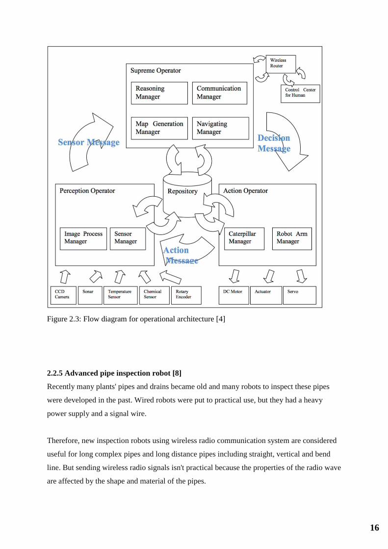
present here a discussion of the performed results. As we can see Figure 2.3 shows the robots
operational architecture [4]
16
Figure 2.3: Flow diagram for operational architecture [4]
2.2.5 Advanced pipe inspection robot [8]
Recently many plants' pipes and drains became old and many robots to inspect these pipes
were developed in the past. Wired robots were put to practical use, but they had a heavy
power supply and a signal wire.
Therefore, new inspection robots using wireless radio communication system are considered
useful for long complex pipes and long distance pipes including straight, vertical and bend
line. But sending wireless radio signals isn't practical because the properties of the radio wave
are affected by the shape and material of the pipes.

17
For these reasons, it measured the properties of wireless radio signal with steel pipes and
ceramic pipes and it developed a practical wireless radio communication system. On the other
hand, the Indian Institute of Technology Kanpur has researched a rotating probe using piezo
element for inspecting the inside of pipes with a touch sensor system. This time, we
developed and tested a new inspection robot that had integrated both the inspection system
using wireless radio communication and image transmission developed by Waseca University
and the inspection system using the rotating probe developed by the Indian Institute of
Technology.
In this experiment, it was confirmed that it could drive the robot by wireless radio
communication system in the inside test pipe and collect the image and some signals from the
rotating probe.
Figure 2.4: Final prototype [8]

18
2.3 Comparative Study
There has been significant amount of research that has been done in the field of gas
pipe cleaning. After going through the literature review we have decided to divide the
project deliverability and features into categories. Reading the literature review has
enabled us to understand better how the project can be implemented
Table 2.2: literature review of the project
Autonomo
us
Cleaning
Video
Feedback
PIG
(Pipeline
inspection
gadget)
Jet Cleaning
(Other than
mechanical
brushing)
Cleaning
(with metal
brush)
Remote
control
Inspection
Literature
review 1[1]
NO NO NO NO NO YES NO
Literature
review 2 [2]
SEMI NO NO NO YES YES YES
Literature
review 3 [3]
YES NO NO NO YES YES Sensors
Literature
review 4 [4]
YES NO NO YES YES YES YES
Our project:
The pipe
inspecting
and cleaning
robot
NO YES NO NO YES YES Manual
As can be seen in table 2 the literature review findings show that robots that have been made
by the institutions concerned have not included all the features that are ideal such as video
feedback. Only our PIAC will have such a feature however the other robots have some other
features such as sensory feedback which will be absent from the PIAC

19
3. System Design
3.1 Design Constraints
3.1.1 Specifications
To complete the project it is very critical to have the project specifications before the
commencement of development. This will ensure the conformity with the standards set.
Below are the specifications of the PIAC:
Video streaming 480p
Vertical movement within the pipe (Max crawl 2km/h)
Wireless control (up to 200 m)
Cleaning metal bristles
Plastic body
7 Megapixels Camera
Integrated joystick for comprehensive control of the robot
Rechargeable Lead acid battery to power the cleaning motor
Rechargeable NiCad battery to run the movement
3.1.2 Design Requirements
The application of this project is industrial. With use of the PIAC in the industrial oil pipes
cleaning and monitoring can easily be performed with utmost ease and professionalism. To
be able to achieve this following critical design requirements must be achieved:
1. In pipe crawling: To navigate within the pipe
2. Cleaning motor with bristles: To clean any built up or slug inside the pipe
3. Long battery life: To ensure practicality of use; for this to be achieved the power
management of the system has to be efficient
4. Wireless control: long range wireless control is critical for the success of the project
as pipelines are made of steel and obstruct the transmission of electro magnetic waves
5. Video streaming: video streaming is critical to check the condition of the pipe before
and after the completion of cleaning

20
3.1.3 Constraints
Several designs constrains have been implicated in the project they are as follows:
Time: there is a severe time constraint for this project, as it has to be completed within the
duration of the course and be submitted for grading. Due to this many processes need to be
cut short and extensive testing also must be avoided.
Pipe size: Initially the main challenge that was faced by the group was to determine the size
of the pipe. This is because one device cannot be developed to fit all sizes. Hence this robot
can only be used to clean pipes of a fixed size.
Range of operation & battery: This robot will have limited distance at which it can operate
and the battery life. These are 2 critical factors that determine the duration and distance it can
be used for
3.1.4 Standards
Since this is a first prototype we will not be implementing any engineering standards.
However in the subsequent implementations we have suggested to have the following
standards:
1. ROHS: (Restriction Of Hazardous Substances) it is environmental certification.
2. CE: (Certified Electronics) with this certification we can be sure it is safe to use.
3. IP 67: water and dust protection.

21
3.2 Design Methodology
Figure 3.1 System architecture
Figure 3.1 shows the system architecture and the relation of the various sub-systems in the project. Due to the complexity of the project it has been divided into multiple sub section the figure
3.2 Below summaries it
Figure 3.2: Project Sub Sections
Broadly the project has been divided into the flowing sub sections:
1. Video monitoring
2. Mobility system
3. Cleaning system
4. Structural design
5. Wireless commination control
6. Wireless video streaming control

22
The methodology we used for the project development was to first brainstorm the way of
implementation. Later several literatures were reviewed to put the objectives of the project
into perspective. We have then simulated and tested the proposed design to study the
feasibility of the project. Below is the first prototype design; this was rejected due to being
ineffective inside the pipe. Figure 3.3 shows the first design simulation made by AutoCAD.
Figure 3.3: First design simulation

23
On subsequent it was decided that 8 wheels would be used to provide better stability within
the pipe (figure 3.3). However even this design was revised to a better version as seen in
figure 3.4
Design parameters
The following design parameters are taken into consideration during the design and
implementation phase of this project
Rotational Speed
The rotational speed of the cleaning motor has to be at least as much as that of the
mobility motor. The expected RPM of the mobility motor should be around 4000
RPM and that of the cleaning motor to be around 7000 RPM
Delivery date
The project is to be completed before 1 Jan 2017
Battery life
The product should be able to clean a I km long pipe on a single charge
Weight
The product shall not be more than 5 Kg
Product cost
The product should not cost more that 10,000 Sr fro development as a prototype
Operating costs
There should be zero operating costs associated with the product except for regular
maintenance

24
Figure 3.4 wheel design proved to be more effective
Figure 3.5 Final physical design

25
Figure 3.6: Breakdown of components
Figures 3.4 shows the initial rejected design; Figures 3.5 and 3.6 show the
final project design
3.3 Product Subsystems and Components
1. Video monitoring
Components used:
Raspberry pi
The Raspberry Pi 3 is the third generation Raspberry Pi. It replaced the
Raspberry Pi 2 Model B in February 2016. Compared to the Raspberry Pi 2 it
has:
1. A 1.2GHz 64-bit quad-core ARMv8 CPU
2. 802.11n Wireless LAN
3. Bluetooth 4.1
4. Bluetooth Low Energy (BLE)
5. Like the Pi 2, it also has:

26
6. 1GB RAM
7. 4 USB ports
8. 40 GPIO pins
9. Full HDMI port
10. Ethernet port
11. Combined 3.5mm audio jack and composite video
12. Camera interface (CSI)
13. Display interface (DSI)
14. Micro SD card slot (now push-pull rather than push-push)
15. VideoCore IV 3D graphics core
16. The Raspberry Pi 3 has an identical form factor to the previous Pi 2 (and
Pi 1 Model B+) and has complete compatibility with Raspberry Pi 1 and 2.
Camera
12V Wireless Camera System. Water-resistant Wide, 110-degree viewing
angle; Wireless transmitter; LCD screen has Standby and Auto-On; Adjustable
arm with suction cup.
LED illumination
Radio TX RX
This module is used for the wireless transmission and reception of signals
mainly used for controlling the PIAC
Wi-Fi streaming (Optional)
Wifi stream has the application of streaming the video
2. Mobility system
Components used:
Atmel 328
Arduino/Genuino Uno is a microcontroller board based on the ATmega328P
(datasheet). It has 14 digital input/output pins (of which 6 can be used as
PWM outputs), 6 analog inputs, a 16 MHz quartz crystal, a USB connection, a
power jack, an ICSP header and a reset button. It contains everything needed
to support the microcontroller;

27
Motor controller
The Arduino Motor Shield is based on the L298. Which is a dual full-bridge
driver designed to drive inductive loads such as relays, solenoids, DC and
stepping motors. It lets you drive two DC motors with your Arduino board,
controlling the speed and direction of each one independently. You can also
measure the motor current absorption of each motor, among other features.
The shield is TinkerKit compatible, which means you can quickly create
projects by plugging TinkerKit modules to the board.
DC motor
1. RF-1220 electrical dc motor
2. Round shape and plastic end cap
3. Lower noise and high speed
4. Dia12*L20mm
5. Long lifetime
Switching protection (TIP 120)
The switching protection system is used to save the controller from being burnt.
Using the system high power is isolated from the controller.
3. Cleaning system
Components used:
Atmel 328
Arduino/Genuino Uno is a microcontroller board based on the ATmega328P
(datasheet). It has 14 digital input/output pins (of which 6 can be used as
PWM outputs), 6 analog inputs, a 16 MHz quartz crystal, a USB connection, a
power jack, an ICSP header and a reset button. It contains everything needed
to support the microcontroller;

28
Motor controller
The Arduino Motor Shield is based on the L298. Which is a dual full-bridge
driver designed to drive inductive loads such as relays, solenoids, DC and
stepping motors. It lets you drive two DC motors with your Arduino board,
controlling the speed and direction of each one independently. You can also
measure the motor current absorption of each motor, among other features.
The shield is TinkerKit compatible, which means you can quickly create
projects by plugging TinkerKit modules to the board.
DC motor
1. RS-360/365H motor:
2. Dia27.7*L32.6mm
3. High quality and the best service
4. 3/5 slots armature
5. Metal end cap
6. Switching protection (TIP 120) (Optional)
4. Structural design
Components used:
Solid works :
Solid works was used for the simulation of the structure before actual building
of the prototype.
Laser printing
For making the cleaning brush as seen in image 3.6 precise lasers cutting was
used. Plastic was laser cut taking into consideration the diameter of the pipe

29
5. Wireless commination control
Components used:
Wifi protocol
IEEE 802.11 is a set of media access control (MAC) and physical layer (PHY)
specifications for implementing wireless local area network (WLAN)
computer communication in the 900 MHz and 2.4, 3.6, 5, and 60 GHz
frequency bands. They are created and maintained by the Institute of Electrical
and Electronics Engineers (IEEE) LAN/MAN Standards Committee (IEEE
802). The base version of the standard was released in 1997, and has had
subsequent amendments. The standard and amendments provide the basis for
wireless network products using the Wi-Fi brand. While each amendment is
officially revoked when it is incorporated in the latest version of the standard,
the corporate world tends to market to the revisions because they concisely
denote capabilities of their products. As a result, in the marketplace, each
revision tends to become its own standard.
Bluetooth HC 06 (Optional)
Bluetooth is a wireless technology standard for exchanging data over short
distances (using short-wavelength UHF radio waves in the ISM band from 2.4
to 2.485 GHz) from fixed and mobile devices, and building personal area
networks (PANs). Invented by telecom vendor Ericsson in 1994,it was
originally conceived as a wireless alternative to RS-232 data cables.
Zigbee RX TX
ZigBee is an IEEE 802.15.4-based specification for a suite of high-level
communication protocols used to create personal area networks with small,
low-power digital radios, such as for home automation, medical device data
collection, and other low-power low-bandwidth needs, designed for small
scale projects which need wireless connection.
The technology defined by the ZigBee specification is intended to be simpler
and less expensive than other wireless personal area networks (WPANs), such
as Bluetooth or Wi-Fi. Applications include wireless light switches, electrical

30
meters with in-home-displays, traffic management systems, and other
consumer and industrial equipment that requires short-range low-rate wireless
data transfer.
Zigbee explorer dongle
3.4 Implementation
This project is divided into the following sub-systems
1. Video monitoring
2. Mobility system
3. Cleaning system
4. Structural design
5. Wireless commination control
6. Wireless video streaming control
7. Mechanical design
Figure 3.7 Sub systems of PIAC

31
3.4.1 System integration
During system integration we had the challenge of integrating the different sub systems into
one final product. Overcoming several challenges did this. We will look onto each sub system
in detail:
1. Mobility system
Figure 3.8 Mobility system Figure 3.8 represents the parent system of the motors sub- system
The motor connections on the Ardiuno board can be seen below. As can be seen the
motors are connected to the TIP 120 Darlington pain transistors to protect the Arduino
controller. The Arduino uses a PWM pulse to operate the motors. This is represented
in figure 3.9
Figure 3.9 Motor connections to controller

32
2. Cleaning system
Figure 3.10 Cleaning system Figure 3.10 represents the parent system of the cleaning motors sub- system. In this system the brush was custom designed to fit the mouth of the pipe. The motor is controlled in a very similar way like the mobility motors
Laser cutting:
Laser cutting was employed to cut the frame for the cleaning brush
Figure 3.11 Laser cutting of plastic sheet
A large plastic sheet is cut as seen in figure 3.8 and this is used to make the cleaning
brush. At the end of the cleaning brush structure the bristles are attached to create
friction

33
3. Mechanical design
Figure 3.12 3D design and implementation Figure 3.12 represents the parent system of the 3D design and implementation sub-system
Central Frame
Figure 3.13 As seen in figure 3.13 the three transitional elements in the PIAC and their placement is depicted.
Translational Elements
The translational parts of the project are the ones that move. in the PIAC the
following parts move.
i. Mobility motor front
The mobility front motor has a smaller wheelbase (12cm) this makes
the robot more structurally stable and reduces the friction.
ii. Mobility motor rear
The mobility rear motor is more powerful and has a wider wheelbase
(22 cm). The wider wheelbase prevents tilting of the PIAC.
iii. Cleaning motor
The cleaning motor is centrally located and as the PIAC enters the pipe
makes an even contact at the top and bottom of the pipe.

34
Calculations and formulas
i. Static analysis
Figure 3.14 Static analysis Figure 3.14 explains the statics of the wheels. The translational elements are 3 in the PIAC as explained above. As the wheels are incident on the pipe forces act in 2 directions perpendicular to each other Fcx and Fcz (as seen in the figure)
ii. Calculation on torque required to turn the cleaning brush
The applied torque is normal moment multiplied with the friction
factor, seen in Eq 3.1 and is valid for both the 2D and the 3D model.
Eq 3.1
From Eq., a vertical bend (equal to zero) would give no torque, while a
horizontal section (equal to 90 degree) applies the maximum torque.
For the case with only rotation, axial friction has no effect, and the
direction of the motion plays no role on the torque.
Please note we only consider torque in straight sections. In curved

35
sections it is not calculated as the robot will only operate in straight
pipes. The PIAC can later be modified to operate in curved sections
iii. Friction factor
Eq. 3.2
Figure 3.15 Friction vs applied force Figure 3.15 shows that as in the beginning the brush requires a lot more torque as opposed to when the movement has already started. The frictional losses reduce as the motion begins As a force is applied to an object, the region for static friction last until the force is great
enough to overcome the initial resistance to move the object. Kinetic friction is on the other
hand valid for objects in movement, and is the one used in torque & drag models. Static
friction on the other hand can be associated with differential sticking environment

36
Table 3.1 Experienced friction factors from over 100 wells drilled by conventional down hole assemblies

37
Figure 3.16 Figure 3.16 represents the project complete with components
4. Wireless commination control
Figure 3.17 Wireless communication control The wireless communication of the PIAC has been divided into 3 sub-divisions namely the camera wireless cleaning, the cleaning wireless sub system and the mobility wireless sub-system this is represented in figure 3.17

38
Figure 3.18 Figure 3.18 shows the connection of the Bluetooth and the raspberry pi. From this it is clear that the Bluetooth module is connected with the GPIO pins of the raspberry pi
5. Wireless video streaming control
Figure 3.19 Figure 3.19 shows the parent sub-system of the camera

39
Figure 3.20 Raspberry pi camera connection The raspberry pi is connected to the camera using a ribbon cable. The connection can be seen in figure 3.20 Design revisions
There were 3 revisions before the final product was finalized these are detailed below
Design 1
The first design was an initial 3D simulation that was proposed for implementation. This
design has many weaknesses such as:
1. Unstable design
2. Very large rear wheels
3. Redundant front wheels
This design can be seen in figure 3.16

40
Figure 3.21 AutoCAD design
Design 2
The second design was also finalized till the implementation stage however because it was
unstable the team had to scrap the design and make a better design. This design can be seen
blow in figure 3.22
Figure 3.22 Previous design rejected due to instability

41
Final Design
Figure 3.23 Final design After much reconsideration and revisions a stable design was achieved as seen in figure 3.23

42
4. System Testing and Analysis
4.1 Motor RPM and torque
4.1.1 Objectives
1. Find the max motor torque & RPM of the front mobility motor 2. Find the max motor torque & RPM of the back mobility motor 3. Find the max motor torque & RPM of the cleaning motor
4.1.2 Setup
1. To test the motor in the pipe using a multi meter 2. To find the torque the current and voltage is needed. For this actual voltage and
current during test are used
HP = V x I x Eff
746 Eq. 4.1
We assume constant torque inside the pipe for simpler calculations and the average efficiency of DC motors is about 65%
3. To find the torque we fist find the max RPM
T = 5252 x HP
Rpm Eq. 4.2
4. Use Matlab to simulate and find out results

43
4.1.3 Results Table 4.1: Horsepower and torque for front mobility motor
At Max RPM 4127 For front mobility motor
T = 5252 x HP/rpm
(lb-ft)
HP = V x I x Eff /
746 V I
4.43532E-05 3.48525E-05 4 0.01
8.87064E-05 6.97051E-05 4 0.02
0.00013306 0.000104558 4 0.03
0.000177413 0.00013941 4 0.04
0.000221766 0.000174263 4 0.05
0.000266119 0.000209115 4 0.06
0.000310472 0.000243968 4 0.07
0.000354825 0.00027882 4 0.08
0.000399179 0.000313673 4 0.09
0.000443532 0.000348525 4 0.1
0.000487885 0.000383378 4 0.11
0.000532238 0.000418231 4 0.12
0.000576591 0.000453083 4 0.13
0.000620945 0.000487936 4 0.14
0.000665298 0.000522788 4 0.15
0.000709651 0.000557641 4 0.16
0.000754004 0.000592493 4 0.17
Table 4.2: Horsepower and torque for back mobility motor
At Max RPM 4400 For back mobility motor
T = 5252 x HP/rpm
(lb-ft)
HP = V x I x Eff /
746 V I
4.43532E-05 3.48525E-05 4 0.01
0.00013306 0.000104558 4 0.03
0.000266119 0.000209115 4 0.06
0.00036961 0.000290438 4 0.083333333
0.000480493 0.000377569 4 0.108333333
0.000591376 0.000464701 4 0.133333333
0.000702259 0.000551832 4 0.158333333
0.000813142 0.000638963 4 0.183333333
0.000924025 0.000726095 4 0.208333333
0.001034908 0.000813226 4 0.233333333
0.00114579 0.000900357 4 0.258333333
0.001256673 0.000987489 4 0.283333333
0.001367556 0.00107462 4 0.308333333

44
0.001478439 0.001161752 4 0.333333333
0.001589322 0.001248883 4 0.358333333
0.001700205 0.001336014 4 0.383333333
0.001811088 0.001423146 4 0.408333333
Table 4.3: Horsepower and torque for cleaning motor
At Max RPM 6600 For cleaning motor
T = 5252 x HP/rpm HP = V x I x Eff /
746 V I
5.15856E-05 6.48257E-05 6 0.0124
0.00026292 0.000330402 6 0.0632
0.000425581 0.000534812 6 0.1023
0.000845754 0.001062828 6 0.2033
0.001032751 0.001297822 6 0.24825
0.001287268 0.001617664 6 0.30943
0.001541785 0.001937505 6 0.37061
0.001796301 0.002257347 6 0.43179
0.002050818 0.002577189 6 0.49297
0.002305334 0.002897031 6 0.55415
0.002559851 0.003216873 6 0.61533
0.002814367 0.003536714 6 0.67651
0.003068884 0.003856556 6 0.73769
0.0033234 0.004176398 6 0.79887
0.003577917 0.00449624 6 0.86005
0.003832434 0.004816082 6 0.92123
0.00408695 0.005135924 6 0.98241
Note: the maximum RPM for the front mobility motor is 4127, back mobility motor is 4400 and the cleaning motor is 6600.

45
4.2 Camera video feedback test
4.2.1 Objectives
1. Test communication range
2. Test battery
3. Test clarity
4. Test angle of view
5. Test lighting
4.2.2 Setup
The camera was tested outside the pipe for varying conditions to be created
4.2.3 Results
After the testing the following results were achieved:
1. Battery life (Only of camera without motors running ): 1h
2. 110 degrees viewing angle
3. Good clarity
4. Range: 50 m
Figure 4.1 Camera image retrieved during testing

46
4.3 Movement and cleaning
For each subsystem mention the test:
4.3.1 Objectives
1. To check if cleaning is affective
2. To find if the torque is sufficient
3. If the robot is stable
4. Test angle of view
5. Test lighting
4.3.2 Setup
The robot is placed inside the pipe and a cleaning is simulated
Pipe calculations and specifications:
Radius of the pipe opening (Inside): 5 Inches
Diameter = 2* Radius = 10 inches
Kind of corrosion inside the pipe: General attack corrosion
Level of corrosion inside the pipe: Mild to moderate
47
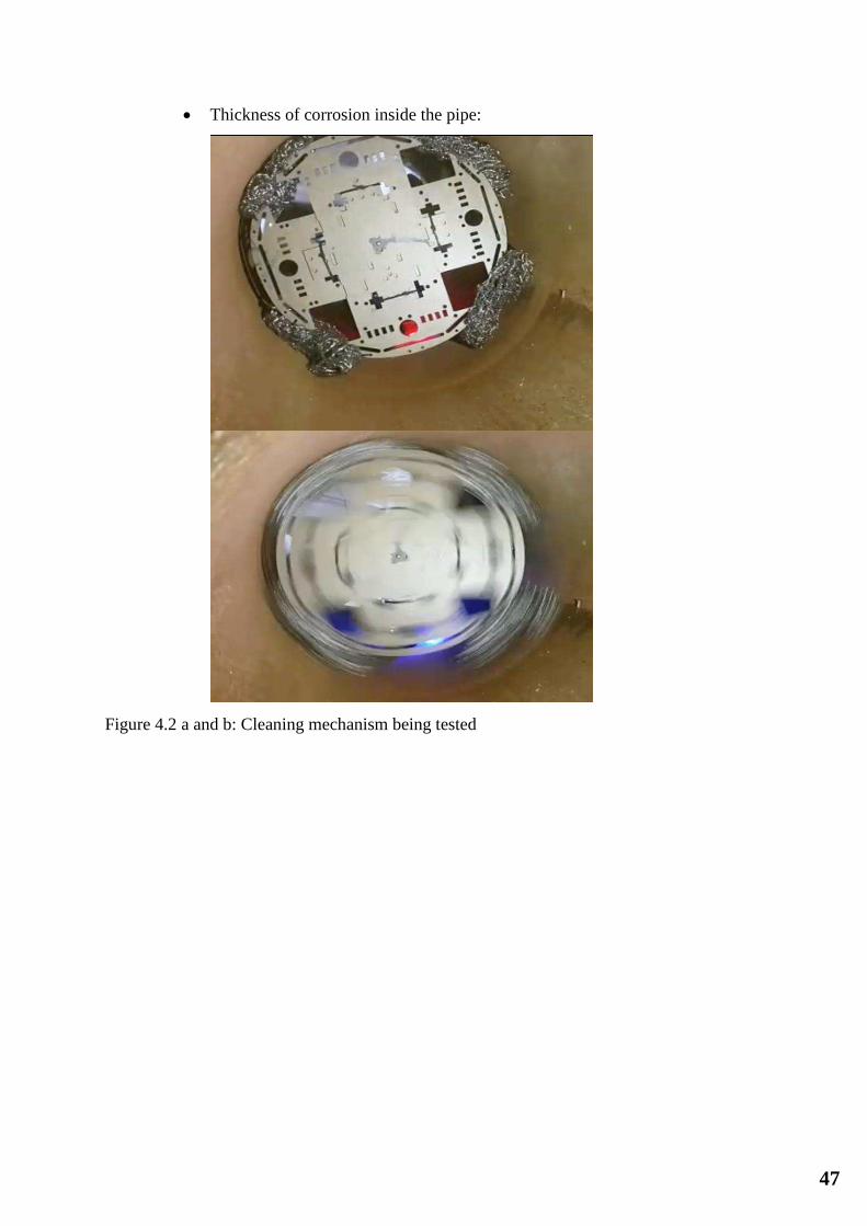
Thickness of corrosion inside the pipe:
Figure 4.2 a and b: Cleaning mechanism being tested

48
4.3.3 Results
After the testing the following results were achieved:
1. The robot did not move with the lower power motors (Higher torque motors were
added)
2. The robot did not clean the bottom of the pipe (The cleaning brush pipe was
readjusted)
3. There was significant difference in color and appearance on the interior of the pipe
after cleaning.
4. Due to cleaning the rust was dropped and dissipated in the form of a dusty cloud
5. The amount of rust removed in the pipe was approximately 4 grams this could be
calculated by weighing the dust after the process of cleaning

49
4.4 Overall Results, Analysis and Discussion
The over all results of the testing are detailed in the following steps:
4.4.1 Setup:
The setup for the test was as follows:
1. Video transmission ON
2. All motors turned ON (Mobility and cleaning)
3. Battery initially fully charged
4.4.2 Analysis:
For the analysis the following parameters were observed:
1. Battery life
below is the battery consumption figure of the lead acid battery
Figure 4.3-battery consumption diagram of the 12V battery
The figure 4.3 above shows the battery consumption curve versus time
2. Cleaning area of 0.398 m2 was used for testing (Half meter pipe with 10 inch
diameter)
For this test the PIAC was put inside the pipe and made to clean the interior.
Adjustments had to be made to clean the bottom and the top evenly

50
Figure 4.4 Cleaning brush test
3. Motor current consumption
The DC motor current consumption diagram can also be seen below as seen as the
load increases the current consumed also increases
Figure 4.5 DC motor characteristics under various conditions
The figure 4.5 shows the motor characteristics of the DC motor
Results changes and observations:
1. At excessive required torque there is exponential consumption of power

51
2. Motors consumes a peak in power during startup
3. The brush angle was not correct and the cleaning was not even
4. The maximum RPM of the mobility motors was 4400 and 4130 RPM whereas the
max torque of the cleaning motor was 6600 RPM
5. The values of torque at different values of current is represented in section 4.1

52
5. Project Management
5.1 Project Plan
Our project has been divided into the following tasks and in the figure 5.1 we have slit it
into the execution timeline:
1. Finalize team: this step involves the selection of the team members and forming a
team officially. This has to be made official with the course instructor
2. Brainstorm ideas: The selection of ideas is the most interesting as our team decides
the ideas that will most appropriately display our understanding of our degree, fit in
our budget and interests all the group members. After the project is finalized an
approval must be sough from the instructor to confirm commencing work on the
project
3. Literature review of ideas
After the finalizing of the project ideas it was very important to acquaint ourselves
with similar projects that were done with a similar title and functionality. This is a
continuous process and will require reading and summarizing academic journals
4. Finalize ideas
Ideas need to be finalized and the product features and objectives may need to be
determined these decisions can be based on the knowledge gained from the literature
review
5. Prepare first report and presentation
After finalizing the project and its features an official presentation needs o be done in
front of the department. This involves some progress in terms of the prototype,
calculations and simulations. Critical feedback will be give during this session that
can be used to mold the project in the right direction
6. Work on the structure of the robot
Before finalizing or starting work on the electronics of the project it was very
important to work on the structure of the project. We need to make sure that the
structure is stable and can easily house the static and translational components of the
project
7. Final design of structure

53
After several trials we are expected to finalize the design of the project. After this step
the actual building of the prototype structure is required
8. Build structure
The structure is actually built with the confirmed design and using the decided
materials of use
9. Design cleaning blade
In this project the cleaning blade will depend on the design of the prototype structure.
This step requires laser cutting of plastic sheets of exact size to create the mold of the
cleaning brush. Cleaning bristles are attached to the blade accordingly
10. Video streaming
As mechanical engineers this is the most difficult step for the group we need to make
a wireless camera that sends video to the controller
11. Test sub-systems separately
Each sub system needs to be tested separately before we combine them all
12. Movement addition
The 3 translational components of the system need to be made separately (3 motors)
13. System integration
All systems need to be combined
14. System testing
The complete project is tested for effectiveness
15. Final Report
1 2 3 4 5 6 7 8 9 10 11 12 13 14 15

54
1.2 Contribution of Team Members
As can be seen above our tasks are well divided. Each team member is responsible fro a part of the
project
Abdullah Al Deghreer 25% Mohammed Alyami 25% Naif Al Mahasheer 25%
Programming System integration Structural building
Team management Finance handling
Materials procurement
Ahmed AlShalawi 25%
Electrical work & testin
5.3 Project Execution Monitoring
Week 1
Week 2
Week 3
Week 4
Week 5
Week 6
Week 7
Week 8
Week 9
Week 10
Week 11
Week 12
Week 13
Week 14
Week 15
Figure 5.1 Tasks chronological breakdown

55
For the successful execution of the project it was critical to organize and have regular
meetings with the advisors. Here were the following steps taken to monitor project execution
Meeting advisors every 2 weeks to discuss project details
3 team meetings every week in the initial part of the project
Team meetings increase as work load increases
Testing was done using an actual sized pipe
Synergy is something we believe in hence all of the team members had involvement
in the others work
5.4 Challenges and Decision Making
There were several challenges that we faced during the project. This project had to be made
from scratch and there was no platform or readymade solution for it hence each system is
separate and it had to be integrated into the final product. The following were the main
challenges and also how we have overcome them

56
Structure of the PIAC: The structure of the PIAC was changed 3 times because the first 2
designs were not stable. Hence finally we choose a design that has different wheelbase for the
rear wheel giving better stability
Camera streaming: the camera system used to stream the live video from the PIAC is banned
in Saudi Arabia (Wireless camera systems banned in KSA). This led us to search for the
camera in Bahrain and also Dubai but it was not available anywhere. To come around this
problem we decided to make a custom wireless camera
Familiarity with electrical systems: As mechanical engineering students it is important to
understand basic electronics however our project demanded much more and we had to learn
tremendously to overcome this challenge
5.5 Project Bill of Materials and Budget
The project budget was limited to ten thousand riyals. However as engineers we are
always looking to cut on the costs of the product design without undermining the
objectives. Overall we have remained in budget and are proud of the team for this
achievement.

57
The main expense of this project was expected to be the electronic components but
however with careful planning this was kept under check
Sno Description Qty Total
1 Arduino 1 160
2 Radio transmitter 1 220
3 Camera 1 250
4 Camera Transmitter 1 210
5 Camera receiver 1 210
6 Circuit components Na 60
7 Structure Na 400
8 Batteries 2 60
9 Ferro connectors NA 10
10 Wires (single core) 1 bundle 25
11 Connecting wires 1 roll 60
12 Relay 1 20
13 Relay holder 1 15
14 Radio receiving board 24 MHz 1 45
15 Radio transmitting board 24 MHz 1 45
16 Motors 4 400
17 Raspberry Pi 1 250
18 Packaging NA 1000
19 Lazer cutting 1 200
20 Bristle for cleaning 1 pack 20
21 Wire roll 1 60
22 Box for transmitter 1 50
Total 4360
2. Project Analysis
6.1 Life-long Learning
There is a plethora of knowledge, skills, and experiences that we have acquired by our own
(by way of self-learning, independent learning) while working on this project. These are the
following technologies used:
New hardware devices (Arduino, temperature & humidity sensor , Wi-Fi, humidity
sensors, actuators)

58
3D modeling tools
New software tools (Arduino IDE)
Project management skills,
Time management skills,
Team management
Deadline management
System integration
System testing
Debugging skills
Overcoming technical challenges
Working under pressure
Laser cutting
Corrosion types
Pigging technology and its applications
Team work
Task delegation
Report writing
Presentation skills
Product engineering
Making literature review
Working with Lead acid batteries
DC motors
LED arrays
Wireless technologies
6.2 Impact of Engineering Solutions
The costs of removal or treatment of waste from plants has become a major expense to many
liquid processing companies. Additionally, changes in legislation and restrictions from
environmental policies can require extra resources and incur further costs.
An effective way of reducing these costs while promoting carbon footprint reduction is to pig
the product transfer pipelines. This significantly reduces waste and associated costs, and the
environmental benefits of pigging are significant.

59
In today's environment, raw material, manufacturing, and waste disposal costs are rising. At
the same time, customers are placing smaller more frequent orders and demanding higher
product quality. Pigging systems provide significant cost savings by recovering previously
lost product that was trapped in pipelines and eliminating flush waste and disposal expense.
Pigging systems help manufacturing plants become more competitive, attain continuous
improvement goals, and become better stewards of the environment.
Often products that remain trapped in process piping are flushed after transfer with a cleaning
media or the next product in the campaign. Disposal methods for the resulting flushed
product can range from dumping down the sewer drain to collection for burning as hazardous
waste disposal. Pigging systems help by preventing this unnecessary waste stream from
directly entering the environment or pollution from waste processing facilities.
Every pound or gallon of waste product represents a consumption increase in a natural
resource. Pigging systems conserve natural resources by preventing the generation of
product waste.
Liquid manufacturing companies across the world now see Carbon Footprint Reduction as a
marketing tool as well as an ethical approach to business. Pigging can significantly reduce
your organizations direct and indirect Carbon Footprint, which is a key benefit to many
organizations.
For example, the power resources saved by reducing cleaning times and associated waste are
often considerable. Indirectly, the reduction in numbers of tankers or trucks required for
removal of waste or delivery of waste treatment chemicals also reduces things like road
degradation, exhaust emissions and traffic congestion. [9]
6.3 Contemporary Issues Addressed
Put simply the PIAC systems help you recover more useable product from your
processes, you have more product to sell. But that’s not the only way they help you
increase your profits, productivity and efficiency. Product recovery and pigging
systems streamline processes, reducing effort required and making various operations
a lot quicker. They can even eliminate some process stages altogether.

60
Because they massively reduce waste and increase yields along with productivity and
efficiency, PIAC systems deliver a high return on investment. The payback time is
also low. Typically, if you choose a PIAC solution, your savings will pay back the
initial cost of the system in less than one year. So after the first year, it’s nearly all
profit. That makes a great business case for including pigging as part of your liquid
processing operation.
By increasing product yields through pigging, there’s less product to send to waste.
What’s more, the cleaning and changeover processes also use less cleaning fluids and
water. In this way hygienic product recovery and pigging systems directly reduce
waste processing costs. [9]
Evermore stringent environmental restrictions continue to drive up flush waste
disposal costs. As plant production expands increasing demands are placed on both
on-site and public waste treatment facilities.
Pigging systems reduce the generation of flush product waste thereby increasing the
service life of treatment facilities and lowering the cost of municipal waste disposal.
PIAC systems may qualify for credits other incentives based on their environmental
impact. Pigging Solutions continuously monitors current legislation and trends for
potential tax credits and incentives eligible to clients.
7. Conclusions and Future Recommendations
7.1 Conclusions
The PIAC project has achieved its initially set objectives and we have
finally been able to make a robot that cleans the inferiors of the pipes
wirelessly and also monitor it. During our testing we were able to see that
there could be many improvements made in the system such as the pipe was
cleaned a little better on the top side than the bottom side. This problem is
resolved repositioning the rotor of the cleaning brush in the middle
From our literature review we are able to see several implementations of the
idea. Some of them were highly sophisticated well-funded research projects.

61
However we got great insight through them and were able to take cues from
their design
The PIAC robot was built with a plastic structure and the cleaning brushes
were made up of laser cut glass and metal bushes. With this project were
able to clean the interior of metal pipes and simultaneously stream live
video from the interior to monitor the process of cleaning. The robot has a
total of 3 motors as seen in the report. 2 of the motors are used for mobility
and the other single motor is used for cleaning the interior of the pipe. We
have also tested the cleaning capability of the motor as explained in
previous parts of the report and found out that the robot is effectively able to
clean the interior of the pipe. This was verified by the visual difference seen
after the completion of the cleaning process
Our project only works on a pipe of fixed diameter 10 inches in this case.
We would definitely like to overcome this challenge in the future. There are
many things that we learnt during the course of this project, which includes
problem solving, undertaking pressure, electrical systems, 3D modeling and
system integration. The project is especially challenging to the mechanical
engineering students because of the electronics that are involved in it.
7.2 Future Recommendations
This is the first implementation of the project and hence there is huge scope of
improvement in the future. Some of the areas where improvement should be sought
include the following:
1. Versatility: currently the PIAC only works with pipes of fixed diameter. This has to
be corrected in the future enabling the robot to work with different sizes of pipes and
even at horizontal and vertical angles.
2. Battery life: currently a 1.2 AH 12V lead acid battery is used to power the system.
Due to the low capacity of the battery the system runs out of charge relatively quickly.
This should be corrected in the future with the use of larger size batteries and also by
improving the over efficiency

62
3. Engineering standards: since this build is the first prototype just to prove the concept
no engineering standards are approved. In the later build basic electrical NEC, IEEE
and mechanical ASME standards should be included certifications

63
8. References
[1] Jong-Hoon Kim (2008 ) Design Of A Fully Autonomous Mobile Pipeline Exploration Robot
(Famper), B.E., Seoul National University Of Technology In Seoul, South Korea
[2] Safuan Naim Bin Mohamad (July, 2012) Fully Autonomous Pipeline Cleaning Robot Universiti
Teknologi Malaysia
[3]Shyam Lal Sharma, Abdul Qavi & Kamlesh Kumari (2014) Oil Pipelines/Water Pipeline Crawling
Robot For Leakage Detection/Cleaning Of Pipes Al Falah School Of Engineering And
Technology, India
[4]Luis A. MateosӒ, Markus Vincze (2013) In-Pipe Cleaning Mechanical System For Dewalop
Robot - Developing Water Loss Prevention Automation And Control Institute (ACIN) Vienna
University Of Technology (TU WIEN), Gusshausstrasse 27 - 29 / E376, A - 1040, Austria
[5] H. Choi And S. Roh, “In-Pipe Robot With Active Steering Capability For Moving Inside Of
Pipelines,” In Bioin-
Spiration And Robotics: Walking And Climbing Robots, 2007, Pp. 375–402.
[6] V. G. H. Schempf, E. Mutschler And W. Crowley, “Grislee: Gasmain Repair And Inspection
System For Live Entry Environments,” The International Journal Of Robotics Research, Vol.
22, No. 7-8, Pp. 603–616, 2003.
[7] J. Z. Z. X. Li, “Development Of The Self-Adaptive Pipeline Cleaning Robot,” In Advanced
Materials Research,
2010, Pp. 97–101.
[8] Kentarou.Nishijima, Yixiang.Sun, Rupesh Kumar.Srivastava,Harutoshi.Ogai1and
Bishakh.Bhattacharya (2010) Advanced Pipe Inspection Robot Using Rotating Probe Department Of
Automation, Shanghai Jiao Tong University, China 3Department Of Mechanical Engineering, Indian
Institute Of Technology Kanpur, India
[9] Hygenic Pigging Systems (U.D.) Retrieved From Http://Www.Hps-Pigging.Com/About-
Hps/Benefits-Of-Pigging/ England Wales. Company No. 2974969 VAT No. GB 653 6975 93

64
Appendix A: Progress Reports
SDP – WEEKLY MEETING REPORT
Department of Mechanical Engineering
Prince Mohammad bin Fahd University
SEMESTER: ACADEMIC
YEAR: FALL 2016-2017 Date:
PROJECT TITLE pipe inspecting and cleaning robot
SUPERVISORS
Member Name Present/Absent Arriving on time
1. Abdullah Al Deghreer
201002190
2. Mohammed Alyami
201002191
3. Naif Al Mahasheer
200800447
4. Ahmed AlShalawi
200700542
Task progress report for the last week effort:
# Task description Team member
assigned
Progress
0%-100% Delivery proof
1 Finalize project idea
100 Report
2 Review literature 100 Report
3 Compose Literature review 100 Report
4 Compare proposed project 100 Report
Task allocation for the next week:
# Task description Team member
65
assigned
1 Study materials required
1,2,3,4
2 Order materials 1,2,3,4
3 Finalize physical structure 1,2,3,4
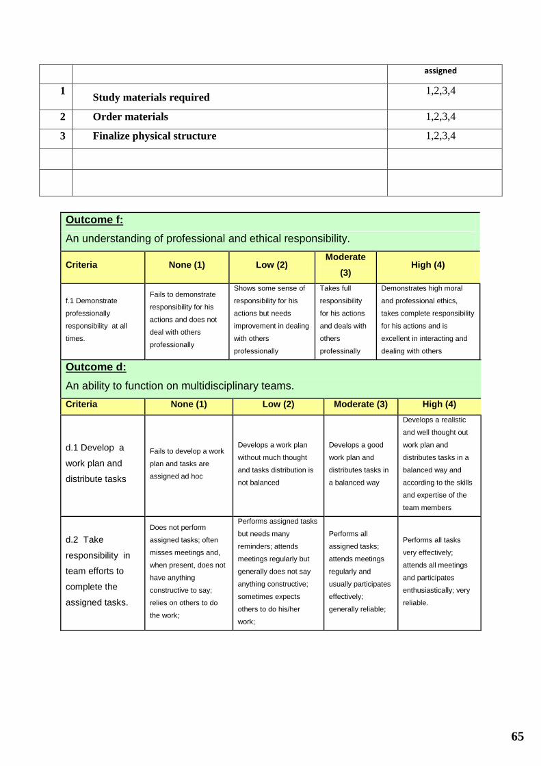
Outcome f:
An understanding of professional and ethical responsibility.
Criteria None (1) Low (2) Moderate
(3) High (4)
f.1 Demonstrate
professionally
responsibility at all
times.
Fails to demonstrate
responsibility for his
actions and does not
deal with others
professionally
Shows some sense of
responsibility for his
actions but needs
improvement in dealing
with others
professionally
Takes full
responsibility
for his actions
and deals with
others
professinally
Demonstrates high moral
and professional ethics,
takes complete responsibility
for his actions and is
excellent in interacting and
dealing with others
Outcome d:
An ability to function on multidisciplinary teams.
Criteria None (1) Low (2) Moderate (3) High (4)
d.1 Develop a
work plan and
distribute tasks
Fails to develop a work
plan and tasks are
assigned ad hoc
Develops a work plan
without much thought
and tasks distribution is
not balanced
Develops a good
work plan and
distributes tasks in
a balanced way
Develops a realistic
and well thought out
work plan and
distributes tasks in a
balanced way and
according to the skills
and expertise of the
team members
d.2 Take
responsibility in
team efforts to
complete the
assigned tasks.
Does not perform
assigned tasks; often
misses meetings and,
when present, does not
have anything
constructive to say;
relies on others to do
the work;
Performs assigned tasks
but needs many
reminders; attends
meetings regularly but
generally does not say
anything constructive;
sometimes expects
others to do his/her
work;
Performs all
assigned tasks;
attends meetings
regularly and
usually participates
effectively;
generally reliable;
Performs all tasks
very effectively;
attends all meetings
and participates
enthusiastically; very
reliable.

66
d.3 Show respect
to other team
members.
Often argues with team
mates; doesn't let
anyone else talk;
occasional personal
attacks and "put-
downs"; wants to have
things done his way and
does not listen to
alternate approaches;
Usually does much of
the talking; does not pay
much attention when
others talk, and often
assumes their ideas will
not work; no personal
attacks and put-downs
but sometimes
patronizing; when others
get through to him,
works reasonably well
with them;
Generally listens to
others' points of
view; always uses
appropriate and
respectful
language; tries to
make a definite
effort to understand
others' ideas;
Always listens to
others and their ideas;
helps them develop
their ideas while
giving them full credit;
always helps the team
reach a fair decision.
Indicate the extent to which you agree with the above statement, using a scale of 1-4 (1=None;
2=Low; 3=Moderate; 4=High)
# Name Criteria (d1) Criteria (d2) Criteria (d3) Criteria (f1)
1 Abdullah Ali Al Deghreer 3 3 4 4
2 Mohammed Alyami
3 3
4 3
3 Naif Al Mahasheer
3 3
4 3
4 Ahmed AlShalawi
3 3
4 3
Comments on individual members
Name Comments
Abdullah Ali Al
Deghreer
All members worked equally
Mohammed Alyami
All members worked equally
Naif Al Mahasheer
All members worked equally
Ahmed AlShalawi
All members worked equally
SDP – WEEKLY MEETING REPORT
Department of Mechanical Engineering
Prince Mohammad bin Fahd University
SEMESTER: ACADEMIC
YEAR: FALL 2016-2017 Date:

67
PROJECT TITLE pipe inspecting and cleaning robot
SUPERVISORS
Member Name Present/Absent Arriving on time
1. Abdullah Al Deghreer
201002190
2. Mohammed Alyami
201002191
3. Naif Al Mahasheer
200800447
4. Ahmed AlShalawi
200700542
Task progress report for the last week effort:
# Task description Team member
assigned
Progress
0%-100% Delivery proof
1 Report corrections (From last week)
All 95 Report
2 Review literature (Continued from last
week)
All 50 Report
3 Literature review (Add more references) All 95 Report
5 Market survey for sample pipe All 0
6 Solid works design All 20 Drawing
Task allocation for the next week:
# Task description
Team member
assigned
1 Basic remote movement
1,2,3,4
2 Scavenge off shelf components (delayed), solid works design (in
progress)
1,2,3,4
3 Appearance and choice of material 1,2,3,4

68
Outcome f:
An understanding of professional and ethical responsibility.
Criteria None (1) Low (2) Moderate
(3) High (4)
f.1 Demonstrate
professionally
responsibility at all
times.
Fails to demonstrate
responsibility for his
actions and does not
deal with others
professionally
Shows some sense of
responsibility for his
actions but needs
improvement in dealing
with others
professionally
Takes full
responsibility
for his actions
and deals with
others
professinally
Demonstrates high moral
and professional ethics,
takes complete responsibility
for his actions and is
excellent in interacting and
dealing with others
Outcome d:
An ability to function on multidisciplinary teams.
Criteria None (1) Low (2) Moderate (3) High (4)
d.1 Develop a
work plan and
distribute tasks
Fails to develop a work
plan and tasks are
assigned ad hoc
Develops a work plan
without much thought
and tasks distribution is
not balanced
Develops a good
work plan and
distributes tasks in
a balanced way
Develops a realistic
and well thought out
work plan and
distributes tasks in a
balanced way and
according to the skills
and expertise of the
team members
d.2 Take
responsibility in
team efforts to
complete the
assigned tasks.
Does not perform
assigned tasks; often
misses meetings and,
when present, does not
have anything
constructive to say;
relies on others to do
the work;
Performs assigned tasks
but needs many
reminders; attends
meetings regularly but
generally does not say
anything constructive;
sometimes expects
others to do his/her
work;
Performs all
assigned tasks;
attends meetings
regularly and
usually participates
effectively;
generally reliable;
Performs all tasks
very effectively;
attends all meetings
and participates
enthusiastically; very
reliable.
d.3 Show respect
to other team
members.
Often argues with team
mates; doesn't let
anyone else talk;
occasional personal
attacks and "put-
downs"; wants to have
things done his way and
does not listen to
alternate approaches;
Usually does much of
the talking; does not pay
much attention when
others talk, and often
assumes their ideas will
not work; no personal
attacks and put-downs
but sometimes
patronizing; when others
get through to him,
works reasonably well
with them;
Generally listens to
others' points of
view; always uses
appropriate and
respectful
language; tries to
make a definite
effort to understand
others' ideas;
Always listens to
others and their ideas;
helps them develop
their ideas while
giving them full credit;
always helps the team
reach a fair decision.
Indicate the extent to which you agree with the above statement, using a scale of 1-4 (1=None;
2=Low; 3=Moderate; 4=High)
# Name Criteria (d1) Criteria (d2) Criteria (d3) Criteria (f1)

69
1 Abdullah Ali Al Deghreer 3 3 4 4
2 Mohammed Alyami
3 3
4 3
3 Naif Al Mahasheer
3 3
4 3
4 Ahmed AlShalawi
3 3
4 3
Comments on individual members
Name Comments
Abdullah Ali Al
Deghreer
We are satisfied by group member performance
Mohammed Alyami
We are satisfied by group member performance
Naif Al Mahasheer
We are satisfied by group member performance
Ahmed AlShalawi
We are satisfied by group member performance

70
Appendix B: Bill of Materials
Sno Description Qty Total
1 Arduino 1 160
2 Radio transmitter 1 220
3 Camera 1 250
4 Camera Transmitter 1 210
5 Camera receiver 1 210
6 Circuit components Na 60
7 Structure Na 400
8 Batteries 2 60
9 Ferro connectors NA 10
10 Wires (single core) 1 bundle 25
11 Connecting wires 1 roll 60
12 Relay 1 20
13 Relay holder 1 15
14 Radio receiving board 24 MHz 1 45
15 Radio transmitting board 24 MHz 1 45
16 Motors 4 400
17 Raspberry Pi 1 250
18 Packaging NA 1000
19 Lazer cutting 1 200
20 Bristle for cleaning 1 pack 20
21 Wire roll 1 60
22 Box for transmitter 1 50
Total 4360 Sr

71
Appendix C: Datasheets

72

73

74

75

76
Appendix D: Program Codes
Arduino codes:
#include <IRremote.h>
#include <Servo.h>
Servo gripper; // create servo object to control a servo
// a maximum of eight servo objects can be created
Servo middle; // create servo object to control a servo
Servo bottom; // create servo object to control a servo
int RECV_PIN = 5;
IRrecv irrecv(RECV_PIN);
decode_results results;
void setup()
{
gripper.attach(9); // attaches the servo on pin 9 to the servo object
middle.attach(10); // attaches the servo on pin 9 to the servo object
bottom.attach(11); // attaches the servo on pin 9 to the servo object
Serial.begin(9600);
irrecv.enableIRIn(); // Start the receiver
}
void loop() {
if (irrecv.decode(&results)) {

77
int a =results.value;
Serial.println(a);
if(a == 2704)
{}
if(a == 2705)
{}
if(a == 2706)
{}
if(a == 2707)
{}
if(a == 2708)
{}
if(a == 2709)
{}
irrecv.resume(); // Receive the next value
}
delay(100);

78
Appendix E: Operation Manual
Below is a general guideline on using the PIAC
1. Running the project prototype
To run the project the following steps need to be taken
a. There are 3 switches that need to be turned on
b. Switch one is to turn on the cleaner blade
c. Switch two is to turn on the mobility motors
d. Switch three is to turn on the camera transmitter
e. After all the 3 switches are turned on the remote needs to be turned on
f. After turning on all the systems test the mobility motor, the camera and the
cleaning motor and make sure the battery is charged full
g. Attach the cleaning brush to the project. Many different types of cleaning
brushes can be used and developed at later stages
h. After attaching the brush insert the PIAC into the pipe; move it using the
controls and clean accordingly
i.
2. Troubleshooting
a. Camera not working:
i. Check if the camera switch is turned on
ii. Check if the receiver is powered on
iii. Check if the batteries are charged
b. Motors not working
i. Check if motor switches are off
ii. Check if the connection with battery is secure
iii. Check the battery charge
c. PIAC stuck in pipe
i. Check if transmitter is powered on
ii. Direct the antenna directly at the opening of the pipe

79

The pipe inspecting and
cleaning robot (PIAC)
Abdullah Al Deghreer
201002190
Mohammed Alyami
201002191
Assessment- Final Year Project
Naif Al Mahasheer
200800447
Ahmed AlShalawi
200700542

Outline
• Recap (Main points of last presentation)
• Objectives
• Grant Chart
• Project Description and functions
• Project Sub systems
• Tasks Accomplished -
• Main Challenges faced
• Demo
• Conclusion

Recap: Main points of last presentation
Project Idea: a robot that will be used to clean the interior of the pipes and also monitoring the interiors
First 3D Model was prepared
Preliminary structure built
Electronics were not installed

Recap: Important Points

Objectives
Build prototype robot with the following features:
Cleaning for 10 inch metal pipe
Wireless video feedback
Sturdy (Strong) design
Battery operated wireless robot

Benefits
Increased pipeline carrying capacity
Improved product quality
Power savings by reducing pump pressure
Confirmation of pipe and flow integrity
Live video streaming
Remote robot control

Grant Chart
1. Finalize team
2. Brainstorm ideas
3. Literature review of ideas
4. Finalize ideas
5. Prepare first report and presentation
6. Work on the structure of the robot
7. Final design of structure
8. Build structure
9. Design cleaning blade
10. Video streaming
11. Test sub-systems separately
12. Movement addition
13. System integration
14. System testing
15. Final report

PIAC: Functional Diagram

PIAC: Description
• 5 Sub Systems:
– Mobility
– Wireless
– Cleaning
– Physical Design
– Video feedback

Ab
du
llah
Mo
ha
mm
ed
Ah
me
dN
aif
System integration:
Checking that the system is working after we have
the system for three days to make sure that it is
working without mistakes.
Finance handling:
The finance handling, purchase and collect.
Programming:
Make the schedule for the meetings and made the
plan to finish the project and divide the work between
the members of our team.
Team management:The leader of the group and was following
with the other members.
Materials selection: Made the decision and select the plastic and discuss that
with the other members and we agree, after that look for the materials and select the best for our project.
Structural building:Contribute in the structural
building of the project.
Pipe providing:Provide the pipe after we
choose the size of it.
Materials purchasing:Purchase the materials after
we select them.
Electrical work:looked for specialist in
electrical and programing and electronics.
Testing:Made the test for the project
to make sure it is working.

3D modeling

PIAC Physical Breakdown

PIAC in action

PIAC controller

Challenges faced
• Camera Banned in Saudi Arabia
• Electrical systems
• Finalizing physical design (3 Times we had to redo physical
design)

Conclusions
• Project Objective achieved
• PIAC is able to clean 10 inch pipes
• Wireless video
• All systems tested and integrated
• More improvements can be done in:
– Adding engineering standards
– Improving battery life

Video Demo
• Please Enjoy our video demo