Embed Size (px)
Citation preview
1
CoLinkEx_LPC11C14 EVB Kit
User Guide
Rev. 1.0 Release: 2012-05-07
Website: http://www.coocox.org
Forum: http://www.coocox.org/Forum/forum.php?id=1
Techinal: [email protected]
Market: [email protected]

2
Revision history
Rev Date Description
1.0 2012-05-07 Initial version

3
1. Catalog
1. Catalog ......................................................................................................................... 3
1. CoLinkEx_LPC11C14 EVB Kit Overview .................................................................... 6
1.1 The Microcontroller Introduction ........................................................................... 6
1.2 Evaluation Boards Introduction ............................................................................. 6
1.3 Hardware resources list ........................................................................................ 7
1.4 Software resources list .......................................................................................... 7
2. CoLinkEx_LPC11C14 EVB Kit Introduction ................................................................. 9
2.1 Board Interface Overview ...................................................................................... 9
2.2 Jumpers settings ................................................................................................... 9
2.3 SW/JTAG Debug Interface.................................................................................. 10
2.4 UART ................................................................................................................... 10
2.5 CAN ..................................................................................................................... 10
2.6 Mini USB Port ...................................................................................................... 10
2.7 LM75 Temperature Sensor ................................................................................. 11
2.8 LED ...................................................................................................................... 11
3. Getting Started ........................................................................................................... 12
3.1 Version Information ............................................................................................. 12
3.2 Hardware Source Requirement .......................................................................... 12
3.3 Preparation .......................................................................................................... 12
3.4 Use the default factory program .......................................................................... 13
4. CoLinkEx Installation and Use ................................................................................... 14

4
4.1 Installation ........................................................................................................... 14
4.1.1 Update the firmware ..................................................................................... 14
4.1.2 Install the Driver of CoLinkEx ...................................................................... 15
4.1.3 Connect CoLinkEx to PC ............................................................................. 18
4.2 Use CoLinkEx ...................................................................................................... 19
4.2.1 How to use CoLinkEx in CoIDE ................................................................... 20
4.2.1 How to use CoLinkEx in CoFlash ................................................................ 23
4.2.2 How to use CoLinkEx in MDK ...................................................................... 26
5. How to use CoLinkEx to debug other devices ........................................................... 29
5.1 CoLinkEx Debug Pin Description: ....................................................................... 29
5.2 Standard 20-PIN SW/JTAG Interface: ................................................................ 29
5.3 Connection method used in SW Debug: ............................................................. 29
5.4 Connection method used in JTAG Debug: ......................................................... 30
6. Examples .................................................................................................................... 31
6.1 Use CoIDE to develop a project .......................................................................... 31
6.2 CoIDE Example Description................................................................................ 34
6.2.1 Blinky ............................................................................................................ 34
6.2.2 UART_Print .................................................................................................. 34
6.2.3 Master_Transfer ........................................................................................... 34
6.2.4 WDT_Reset.................................................................................................. 35
6.2.5 Simple_ADC................................................................................................. 35
6.2.6 Capture ........................................................................................................ 35
6.2.7 Printchar for NXP ......................................................................................... 35

5
6.2.8 Semihosting ................................................................................................. 35
6.2.9 CoOS_App_Framework ............................................................................... 37

6
1. CoLinkEx_LPC11C14 EVB Kit Overview
1.1 The Microcontroller Introduction
CoLinkEx_LPC11C14 EVB Kit uses the LPC11C14x301FBD48 for NXP. The LPC11Cxx
are ARM Cortex-M0 based microcontrollers for embedded applications featuring a high
level of integration and low power consumption.
The LPC11xx operate at CPU frequencies of up to 50 MHz, the peripheral complement of
the LPC11xx series includes up to 32KB of flash memory, up to 8 KB of data memory, one
Fast-mode Plus I2C-bus interface, one RS-485/EIA-485 UART, up to two SPI interfaces
with SSP features, four general purpose timers, a 10-bit ADC, and up to 42 general
purpose I/O pins. It integrated ARM Cortex-M0 built-in Nested Vectored Interrupt
Controller (NVIC), integrated PMU (Power Management Unit) to minimize power
consumption during Sleep, Deep-sleep, and Deep power-down modes.
The LPC11Cxx operates in the -40 to +85 °C temperature range, from a 1.8 to 3.6 V
power supply. A comprehensive set of power-saving mode allows the design of low-power
applications. It includes:
Emetering
Lighting
Industrial networking
Alarm systems
White goods
1.2 Evaluation Boards Introduction
CooCox’s CoLinkEx_LPC11C14 EVB Kit is a brand new, cost-effective but
high-performance evaluation tool of the ARM Cortex-M0 based LPC11xx controller family
from NXP, allowing you to create and test working programs for this advanced
architecture. The board has UART Interface which support RS-485 and EIA-485 modes, 8
channel 10 bit ADC Converter, 2 16bit timer and 2 32bit timer, includes a wide range of
interfaces such as SPI, I2C, integrates PMU(Power Manage Unit). It supports IO
extensions, which is compatible with LPCXpresso Base Board, making it a great starting
point for your next Cortex-M0 project. The onboard adapter: CoLinkEx support MDK and
IAR, help you execute download and debug the project.
You can use the CoLinkEx_LPC11C14 EVB Kit to generate and test application programs
for the NXP LPC11xx microcontroller family. The example and source in the CD will help
you quickly start project development and personal learning.

7
1.3 Hardware resources list
CoLinkEx_LPC11C14 EVB Kit contains CoLinkEx and LPC11C14 board:
On board CoLinkEx LPC11C14_Dev_Board
A mini-type USB socket, power supply
and communicate with PC
CAN Interface
2mm*10pin Debug Interface, can debug
other devices An Serial connection socket ( support RS-485
/ EIA-485)
a power supply LED 1 LED(P2.9)
3 CoLinkEx Status LED: D1~D3 Full function IO extension, support I2C, SPI,
ADC
The suite contains the CoLinkEx_LPC11C14 EVB Kit and the following issues:
MiniUSB Line
2mm*10pin to DB9 serial line
Two 2.54mm Jumper cap
A CD and Publicity Color Pages
1.4 Software resources list
Example Name Function Description
Default factory program LED4 Blink, UART Send data, I2C Read Temperature
sensor
Blinky LED4 Blink
UART_Print UART Send data
Master_Transfer Read data though I2C (Need to connect EEPROM)
WDT_Reset Watchdog application example.

8
Simple_ADC ADC Convert application example.
Capture 32-bits timer capture example
Printchar for NXP Retarget printf to Serial output in CoIDE
Semihosting Retarget printf to Semi hosting in CoIDE(Debug only)
CoOS_App_Framework CoOS simple example for how to create task
9
2. CoLinkEx_LPC11C14 EVB Kit Introduction
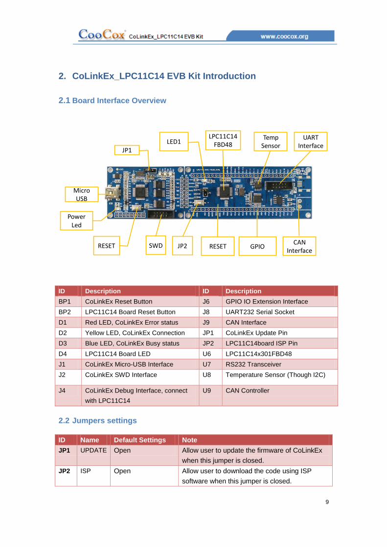
2.1 Board Interface Overview
Micro USB
LPC11C14FBD48
RESETSWD
Power Led
Temp Sensor
GPIOCAN
Interface
LED1
RESET
UART Interface
JP1
JP2
ID Description ID Description
BP1 CoLinkEx Reset Button J6 GPIO IO Extension Interface
BP2 LPC11C14 Board Reset Button J8 UART232 Serial Socket
D1 Red LED, CoLinkEx Error status J9 CAN Interface
D2 Yellow LED, CoLinkEx Connection JP1 CoLinkEx Update Pin
D3 Blue LED, CoLinkEx Busy status JP2 LPC11C14board ISP Pin
D4 LPC11C14 Board LED U6 LPC11C14x301FBD48
J1 CoLinkEx Micro-USB Interface U7 RS232 Transceiver
J2 CoLinkEx SWD Interface U8 Temperature Sensor (Though I2C)
J4 CoLinkEx Debug Interface, connect
with LPC11C14
U9 CAN Controller
2.2 Jumpers settings
ID Name Default Settings Note
JP1 UPDATE Open Allow user to update the firmware of CoLinkEx
when this jumper is closed.
JP2 ISP Open Allow user to download the code using ISP
software when this jumper is closed.

10
2.3 SW/JTAG Debug Interface
CoLinkEx_LPC11C14 EVB Kit use ARM standard 2mm*10 pin SW/JTAG Interface.
You can use this interface to debug other devices. See: How to use CoLinkEx to debug
other devices. You can also use other adapter to debug the LPC11C14board, such as
ULink2, J-Link.
2.4 UART
The Universal Asynchronous Receiver Transmitter features a 9-pin UART that can be
used for communication and trace purposes. It offers an ideal channel for ISP
downloading. Use the following line to connect the board and PC.
2.5 CAN
CAN Interface, use TJA1040 Controller, can connect through J9. It offers an ideal
channel for ISP downloading, too.
2.6 Mini USB Port
A Mini USB AB interface supplies 5V voltage to the Board. CoLinkEx communicate
with the PC through this port.

11
2.7 LM75 Temperature Sensor
A LM75 Temperature Sensor is connected to the I2C bus in CoLinkEx_LPC11C14 EVB
Kit.
2.8 LED
CoLinkEx+LPC11C14_Dev Board provide LEDs D4, it respectively connect with
PIO2.9 IO pins, and can be used for user output.

12
3. Getting Started
3.1 Version Information
Firmware: 0.4
Driver: 1.2.0(or 1.2.1)
Software:
CoIDE 1.4.0 or higher
CoFlash 1.4.0 or higher
MDK 4.03(or higher) plus CoMDKPlugin1.4.0 or higher
3.2 Hardware Source Requirement
When you use CoLinkEx_LPC11C14 EVB Kit, The PC is required to use the following
sources:
CPU: 2.0GHz (at least)
Memory: 512M (at least)
USB Interface: 1 (at least)
Serial Line interface use COM1
Operation System: Windows XP/Windows Vista/Win 7
Software need: CoIDE, MDK, IAR(with CoMDKPlugin, CoIARPlugin)
3.3 Preparation
Install CoIDE or the corresponding Plugin
Update the firmware and install the driver, Refer to: CoLinkEx Installation and
Use
Jumpers’ setting: JP1, JP2 both OFF.
USB Connection: Using USB cable, one end plugged into the Mini USB port on
the board CoLinkEx (J1), the other end connected to PC.
If serial communication is needed:
Serial Connection: Connect com of board and the COM of PC through serial port
cable.
Serial Port Receive Settings: In the PC, run HyperTerminal serial communication
program, select the serial port used and set the following parameters (to set
status: Baud rate (115200), data bits (8 bits), stop bits (1 bit), parity bit (no ), data
flow control (no)).
If CAN Communication is needed:

13
Connect J9 (CAN Interface) with PC or other devices.
3.4 Use the default factory program
The board has load the following program by default. You can use it to test the hardware.
You can also get the code through CooCox CoFlash.
1. Test Objective: The onboard hardware: Adapter, LPC11C14 chip, LED, UART and
Temperature sensor can work normally.
2. Test Hardware Resources: MiniUSB Line, 2mm*10 pin to COM serial line,
CoLinkEx_LPC11C14 EVB (all included in the CoLinkEx_LPC11C14 EVB Kit )
3. Test Prepareation: Connect the lines and set the HyperTerminal, you can refer to 3.3
4. procedure:
1) Power on the board and press the Reset button.
2) HyperTerminal will display “Welcome to use CooCox!” the tests begin.
3) LED Blink Test: The board execute blinky test, D4 will light 5 times, means test
OK. When the execute end, HyperTerminal will display “LED Blink Test OK!”
4) UART Test: HyperTerminal will display “UART Print Test OK!”
5) Temperature sensor and I2C Test: HyperTerminal will display the temperature
value, and “I2C Temperature Sensor Test OK!” when the test ends.
6) When the entire test ends, you will see “All test ended!” on the screen. If your
board works normally, you will see the following lines on the HyperTerminal.
5. If you need to reload the default factory program to the board, you can use CoFlash.
Refer to: How to use CoLinkEx in CoFlash. Just load the “LPC11CxxTest.bin” to your
board.

14
4. CoLinkEx Installation and Use
4.1 Installation
To install CoLinkEx, you need to do the following:
Update the firmware
Install the Driver of CoLinkEx
Connect CoLinkEx to PC
4.1.1 Update the firmware
If you are using CoMDKPlugin V1.4.0, CoIDE V1.4.0, or CoFlash V1.4.0, you need to update CoLinkEx driver and firmware before using CooCox CoLinkEx.
The firmware can be found in the disk: Tools\ColinkEx_Driver\ColinkEx_firmware_v0.4.bin
How to update the firmware:
1)Short-circuit JP1.
2)Connect CoLinkEx to the PC.
Wait for the PC enumerates the removable disk whose label is "CRP2 ENABLD" or "CRP DISABLD". If it does not, you could press the reset button (BP1) for several times or power on again.
Delete the firmware.bin file in removable disk.
3)Copy the downloaded firmware: ColinkEx_firmware_v0.4.bin into the removable disk.
4)Disconnect JP1, power on again, then CoLinkEx will work normally.

15
4.1.2 Install the Driver of CoLinkEx
You need to select the version of CoLinkExUSBDriver according to your Windows OS first.
1) If you're using the 32 bit windows system, for example:
Windows XP/Windows Vista 32bit/Windows 7 32bit.
Installation file: Tools\ColinkEx_Driver\CoLinkExUsbDriver-1.1.0.exe
Do the operations shown in the following picture.

16
17
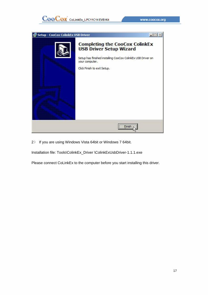
2) If you are using Windows Vista 64bit or Windows 7 64bit.
Installation file: Tools\ColinkEx_Driver \ColinkExUsbDriver-1.1.1.exe
Please connect CoLinkEx to the computer before you start installing this driver.
18
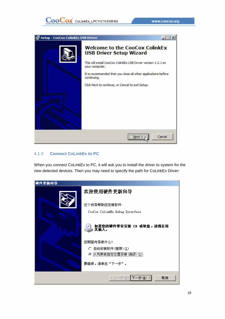
4.1.3 Connect CoLinkEx to PC
When you connect CoLinkEx to PC, it will ask you to install the driver to system for the
new detected devices. Then you may need to specify the path for CoLinkEx Driver:

19
When you install the driver, in device manager, you will found CooCox(COM x)under Port
and CooCox CoLinkEx Debug Interface under USB Controller.
If there “?” in front of the two devices, it means that the driver have not been installed to
the system or install failed; if there isn’t CooCox Port, it means that your CoLinkEx
firmware and driver is old version.
4.2 Use CoLinkEx
Now CoLinkEx support CoIDE, CoFlash 和 CoMDKPlugin. The following is the
configuration to use CoLinkEx in this software.

20
4.2.1 How to use CoLinkEx in CoIDE
1) After create CoIDE Project, click Debug Configuration button:
2) In “debug configuration” page, select CoLinkEx, and set other parameters.
21
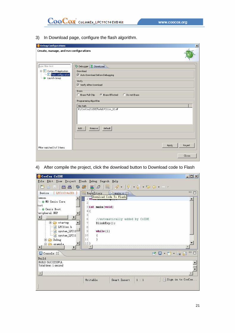
3) In Download page, configure the flash algorithm.
4) After compile the project, click the download button to Download code to Flash

22
5) Click Debug button to debug the program.

23
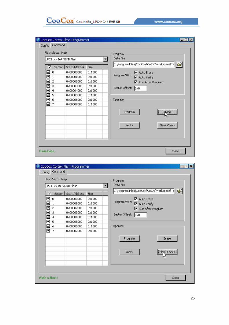
4.2.1 How to use CoLinkEx in CoFlash
1) Open CoFlash, select LPC11C14x301 from NXP, CoLinkEx, and modify the related
parameter if you need. You can refer to the following picture.

24
2) Switch to Download page to execute Download, Erase, Verify, Blank Check, etc.
25

26
4.2.2 How to use CoLinkEx in MDK
1) Open MDK Project, Click Target options to configure the project:
2) “Debug -> Use”, open the configuration dialog and selects "CooCox Debugger".

27
3) Click "Settings", and then select the “CoLinkEx” as the adapter. You can also modify
the Port, Max Clock for the adapter, Reset, Cache, Trace or Semihosting Options, etc.
4) Switch to Flash Download to set the flash options and the flash algorithm.
28
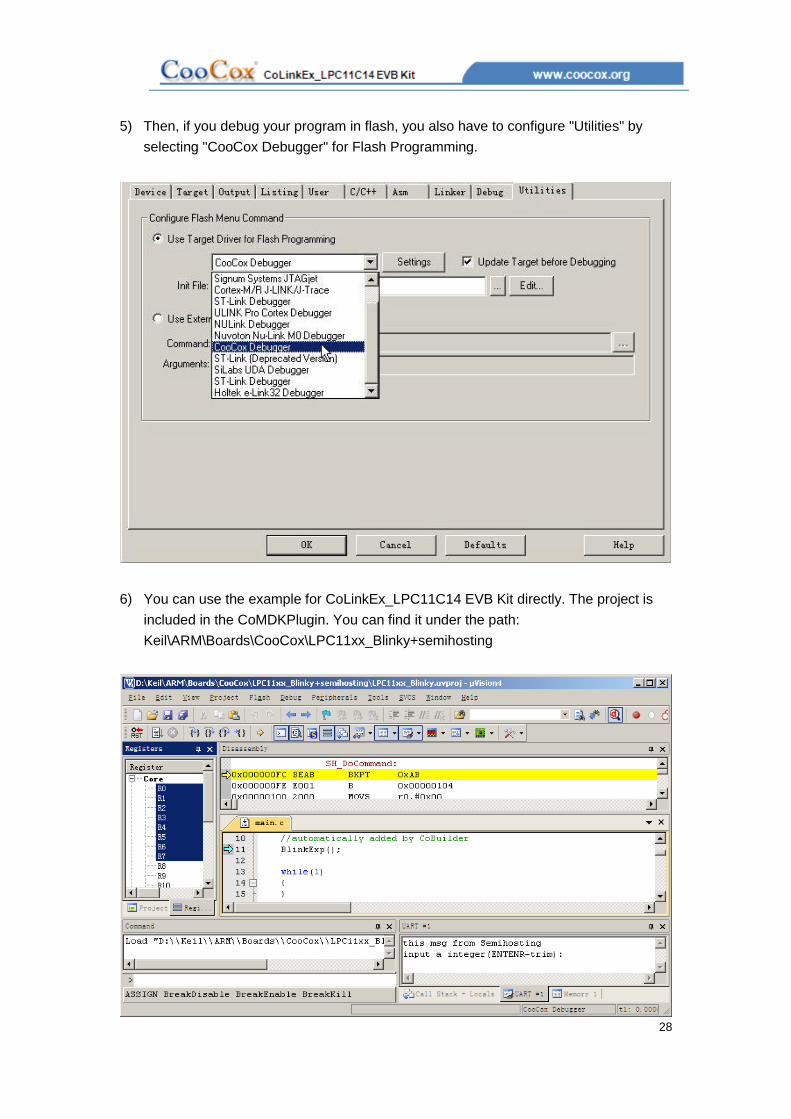
5) Then, if you debug your program in flash, you also have to configure "Utilities" by
selecting "CooCox Debugger" for Flash Programming.
6) You can use the example for CoLinkEx_LPC11C14 EVB Kit directly. The project is
included in the CoMDKPlugin. You can find it under the path:
Keil\ARM\Boards\CooCox\LPC11xx_Blinky+semihosting
29
5. How to use CoLinkEx to debug other devices
If you want to use CoLinkEx to program/debug other devices, you can break off the kit and
use CoLinkEx alone. It is recommended to do that to avoid the disturbance come from the
LPC1114 part. Then you can use the J2 or J4 to connect other devices.
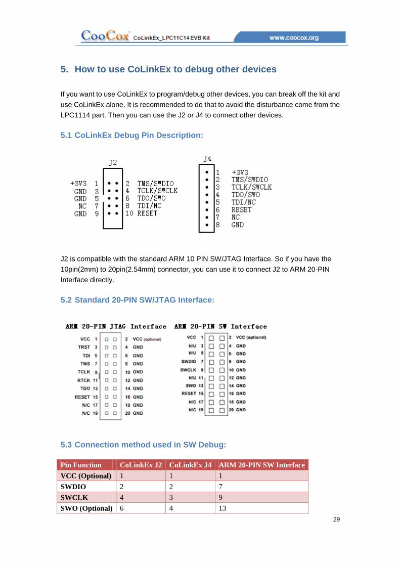
5.1 CoLinkEx Debug Pin Description:
J2 is compatible with the standard ARM 10 PIN SW/JTAG Interface. So if you have the
10pin(2mm) to 20pin(2.54mm) connector, you can use it to connect J2 to ARM 20-PIN
Interface directly.
5.2 Standard 20-PIN SW/JTAG Interface:
5.3 Connection method used in SW Debug:
Pin Function CoLinkEx J2 CoLinkEx J4 ARM 20-PIN SW Interface
VCC (Optional) 1 1 1
SWDIO 2 2 7
SWCLK 4 3 9
SWO (Optional) 6 4 13
30
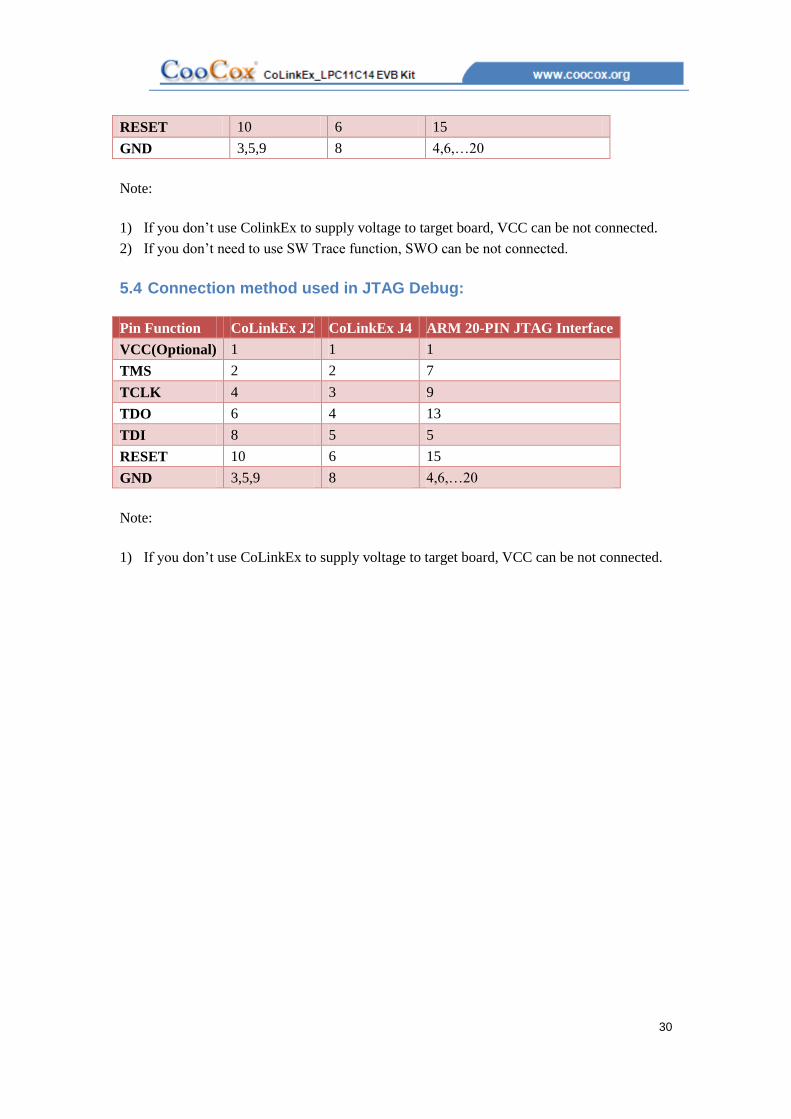
RESET 10 6 15
GND 3,5,9 8 4,6,…20
Note:
1) If you don’t use ColinkEx to supply voltage to target board, VCC can be not connected.
2) If you don’t need to use SW Trace function, SWO can be not connected.
5.4 Connection method used in JTAG Debug:
Pin Function CoLinkEx J2 CoLinkEx J4 ARM 20-PIN JTAG Interface
VCC(Optional) 1 1 1
TMS 2 2 7
TCLK 4 3 9
TDO 6 4 13
TDI 8 5 5
RESET 10 6 15
GND 3,5,9 8 4,6,…20
Note:
1) If you don’t use CoLinkEx to supply voltage to target board, VCC can be not connected.

31
6. Examples
6.1 Use CoIDE to develop a project

32

33
34
You can also go to our website for more information:
CoIDE Quick Start Guide: http://www.coocox.org/CoIDE/CoIDE_QuickStart.htm
CoIDE Guide: http://www.coocox.org/CooCox_CoIDE.htm
6.2 CoIDE Example Description
6.2.1 Blinky
The example shows how to use the LPC111x PIO API to drive a LED.
This example mainly uses the SYSCON and GPIO components. It enable GPIO block
clock and set PIO2_9 to be output and blinking. You can see the D4 Blinking when you
load the project to board.
6.2.2 UART_Print
A simple example shows how to use the UART to print a string.
It sends a “Hello, World!” to UART Interface. After using the Serial line to connect J8 to the
DB9 COM on the computer, you can see the result in HyperTerminal.
The HyperTerminal’s configuration must be:
Baud rate: 115200
Parity: NONE
Data bits: 8 bits
Stop bits: 1 bit
You can see “Hello, World!” in the HyperTerminal screen after you press the reset button
BP2.
6.2.3 Master_Transfer
This example describes how to configure I2C working in master mode, and Read/Write
EEPROM using I2C bus. The example sends some data to EEPROM and then read back.
To use this example, you need to connect LPC11C14 board with an EEPROM: M24C64.
Here is the recommended connection:

35
6.2.4 WDT_Reset
A simple WDT reset example, if TIM_MatchConfigStruct. MatchValue is greater than 8,
Watchdog reset will occur. (Component TMR should be checked). It has no phenomenon
on board.
6.2.5 Simple_ADC
A simple ADC example.
It use ADC Channel 5 to get data, users can select to printf the data through UART printf.
(Need to set UART and retarget printf.)
6.2.6 Capture
A simple example to use TIMER capture function
Use PIO1_5 as the TMR32B0 Capture pin, capture on CAPn.0 rising edge and falling
edge, Generate capture interrupt. You can use printf to get the capture value in the
interrupt function. (Need to set UART and retarget printf.)
6.2.7 Printchar for NXP
Retarget printf to UART of the LPC1100 and LPC11C00 series. If you want to use printf
function in your code, you need to select the “Retarget Printf” component. And use the
Printchar function to replace the one in Printf.c.
6.2.8 Semihosting
This example is a little different from others. If you want to use Semihosting function, you
need to use the example. Then in your application, you can use printf function to print the
code to Semihosting IP. You should enable the Semihosting function in debug
configuration. Then in debug mode, Semihosting will work. It works only in Debug mode.

36
This example shows how to retarget printf to Semihosting output. It cannot be add directly.
You need to copy the content of PrintChar to the PrintChar function in printf.c
It means that you need to use the following code in the example:
#include "semihosting.h"
void PrintChar(char c)
{
/* Send a char like:
While (Transfer not completed);
Transmit a char;
*/
SH_SendChar(c);
}
To replace the following in printf.c:
void PrintChar(char c)
{
/* Send a char like:
While (Transfer not completed);
Transmit a char;
*/
}

37
6.2.9 CoOS_App_Framework
A simple example shows how to create task, init and start CoOS. This example cannot be
automatically added to the application code.
To use this example, you must note the following issues:
CoOS is just an OS, to make it work on LPC11C14, you need to add CMSIS Boot code at
least.
The example contains a main function, so you may need to delete the main.c or move the
main function to that file.
The example is a simple example tells you how to create task, init and start CoOS. It
shows no phenomenon on board. To get more CoOS Applications for that board, you can
go to: http://www.coocox.org/CoOS.htm