Embed Size (px)
Citation preview

67
COLD-GAS PROPULSION FOR SMALL SATELLITE ATTITUDE CONTROL, STATION KEEPING, AND DEORBIT
John G. Furumo
Department of Mechanical Engineering University of Hawai‘i at Mānoa
Honolulu, HI 96822
ABSTRACT
The advent of small satellite technology has opened the final frontier to a whole new class of student explorers. Despite the new space exploration opportunities afforded student engineers and scientists by small satellites, there remain technological limitations on the capabilities of small satellites. Due to their limited size and complexity, mission scope is inherently limited. In order to reconcile the need for a mission-specific orbit with the realities of restrictive launch opportunities as a secondary payload, a cold-gas propulsion system capable of attitude control, orbit maintenance, and deorbit is proposed. Using mostly off-the-shelf parts, a prototype system has been assembled to demonstrate 1-axis control at the Hawai‘i Space Flight Laboratory (HSFL). The system can store compressed air, carbon dioxide, or gaseous nitrogen at up to 31 MPa, providing propulsive capability for a mission lifetime in excess of one year. Solenoid-actuated thrusters capable of providing 0.1-10 N of thrust and 75 seconds of specific impulse have been designed and tested to provide maneuvering power in Low Earth Orbit (LEO). Total system delta-V in the range of 55-75 m/s has been calculated, providing the ability for a small satellite to thrive in a LEO environment ranging in altitude from 350-900 km. After further system characterization and space qualification testing is completed successfully, this system design will be ready to fly in space on the next generation of HSFL small satellites, paving the way for the University of Hawai‘i to become a leader among universities engaged in space exploration.
INTRODUCTION
Most small satellites flown in space up to this point, especially the nanosat and femtosat classes, including cubesats, have not possessed propulsion systems. The conventional wisdom has been to limit development cost and complexity by designing for missions with no orbital maneuverability and passive or low-power means of attitude control. Propulsion provides the ability for a satellite to adjust its orbit and thereby expand altitude-dependent mission options as well as attitude control capability. The overarching goal of this design project was to scale down existing propulsion technology for use in small satellites at a fraction of the cost of existing systems.
Mission Statement: ‘To design a propulsion subsystem for a nanosat-class small satellite and to build and test a prototype unit to validate that design.’

68
In order to have a successful design project, it is necessary to establish functional requirements that the design must meet in order to be deemed satisfactory. For this project these have been established as follows: A. The propulsion system must provide maneuverability to the satellite that it would not
otherwise possess: a. Attitude control – the ability of a satellite to control its orientation in space, necessary
for pointing and detumbling mission phases, a purely rotational maneuver. b. Orbit Maintenance – period orbit boosting to counteract atmospheric drag and extend
mission lifetime at lower altitudes, a purely translational maneuver. c. Deorbit – transfer to a parking orbit or destructive reentry after operational lifetime in
order to mitigate space debris, a purely translational maneuver. B. The proposed system must be able to survive and operate in low earth orbit (LEO) for a 1
year mission lifetime. C. The proposed system may comprise no more than 25% of the total payload mass, volume,
and power budgets, in order to be an effective solution for a small satellite.
Figure 1: Cold-Gas Propulsion System Schematic
Cold-Gas Propulsion
A cold-gas propulsion system was identifies as the most logical and feasible choice for small satellite application. This system type uses high pressure inert gas as a propellant, releasing it through a nozzle to produce propulsive thrust force, much like what happens when a balloon is blown up and then released to fly around the room. The term ‘cold-gas’ simply means that there is no combustion involved. The actual temperature of the gas can vary. Figure 1 shows the basic layout of a cold-gas system; at its simplest, it consists only of a propellant storage vessel, and control valve, and a thruster nozzle.
Pros Cons Simplest propulsion system type Components and propellant gases are
readily available from commercial sources
UH facilities are sufficient for fabrication and testing
Propellants are safe to handle and test with
Relatively low power (low thrust) Limited propellant capacity Least efficient propulsion type (lowest
specific impulse)
69
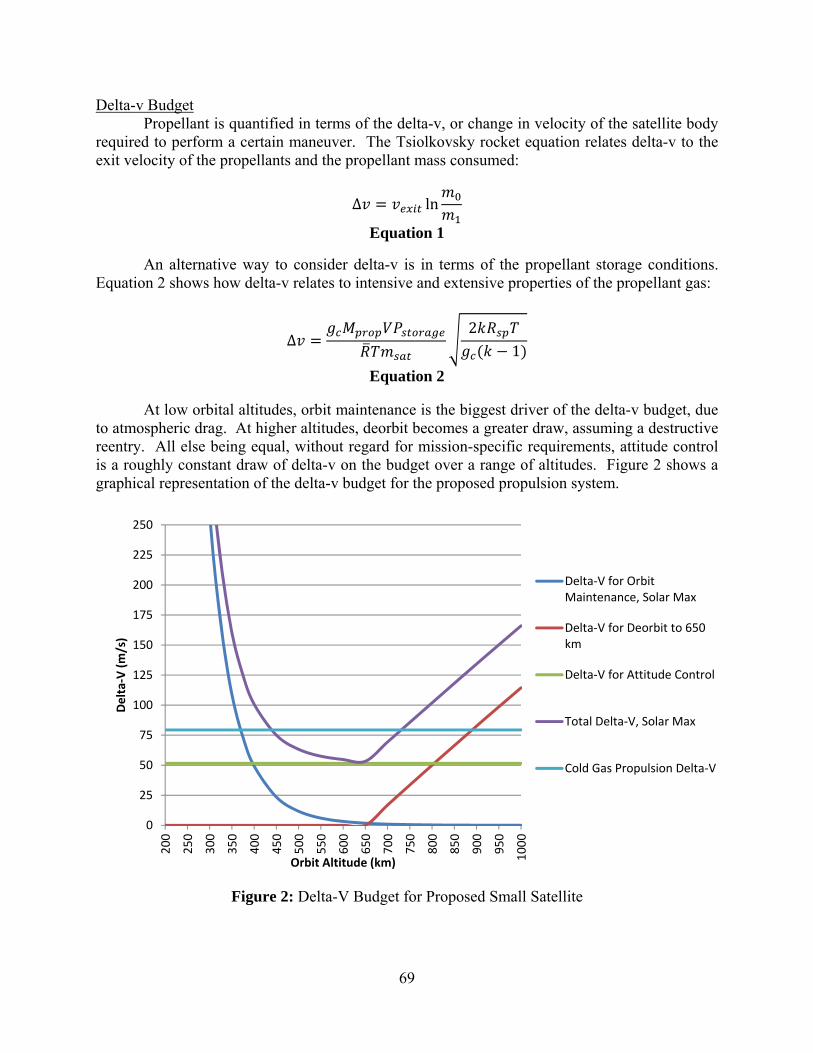
Delta-v Budget Propellant is quantified in terms of the delta-v, or change in velocity of the satellite body
required to perform a certain maneuver. The Tsiolkovsky rocket equation relates delta-v to the exit velocity of the propellants and the propellant mass consumed:
∆ ln
Equation 1
An alternative way to consider delta-v is in terms of the propellant storage conditions. Equation 2 shows how delta-v relates to intensive and extensive properties of the propellant gas:
∆2
1
Equation 2
At low orbital altitudes, orbit maintenance is the biggest driver of the delta-v budget, due to atmospheric drag. At higher altitudes, deorbit becomes a greater draw, assuming a destructive reentry. All else being equal, without regard for mission-specific requirements, attitude control is a roughly constant draw of delta-v on the budget over a range of altitudes. Figure 2 shows a graphical representation of the delta-v budget for the proposed propulsion system.
Figure 2: Delta-V Budget for Proposed Small Satellite
0
25
50
75
100
125
150
175
200
225
250
200
250
300
350
400
450
500
550
600
650
700
750
800
850
900
950
1000
Delta‐V (m/s)
Orbit Altitude (km)
Delta‐V for OrbitMaintenance, Solar Max
Delta‐V for Deorbit to 650km
Delta‐V for Attitude Control
Total Delta‐V, Solar Max
Cold Gas Propulsion Delta‐V
70
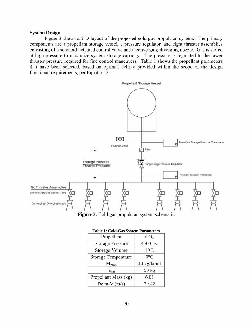
System Design Figure 3 shows a 2-D layout of the proposed cold-gas propulsion system. The primary
components are a propellant storage vessel, a pressure regulator, and eight thruster assemblies consisting of a solenoid-actuated control valve and a converging-diverging nozzle. Gas is stored at high pressure to maximize system storage capacity. The pressure is regulated to the lower thruster pressure required for fine control maneuvers. Table 1 shows the propellant parameters that have been selected, based on optimal delta-v provided within the scope of the design functional requirements, per Equation 2.
Figure 3: Cold-gas propulsion system schematic
Table 1: Cold-Gas System Parameters
Propellant CO2 Storage Pressure 4500 psi Storage Volume 10 L
Storage Temperature 0°C Mprop 44 kg/kmol msat 50 kg
Propellant Mass (kg) 6.01 Delta-V (m/s) 79.42
71
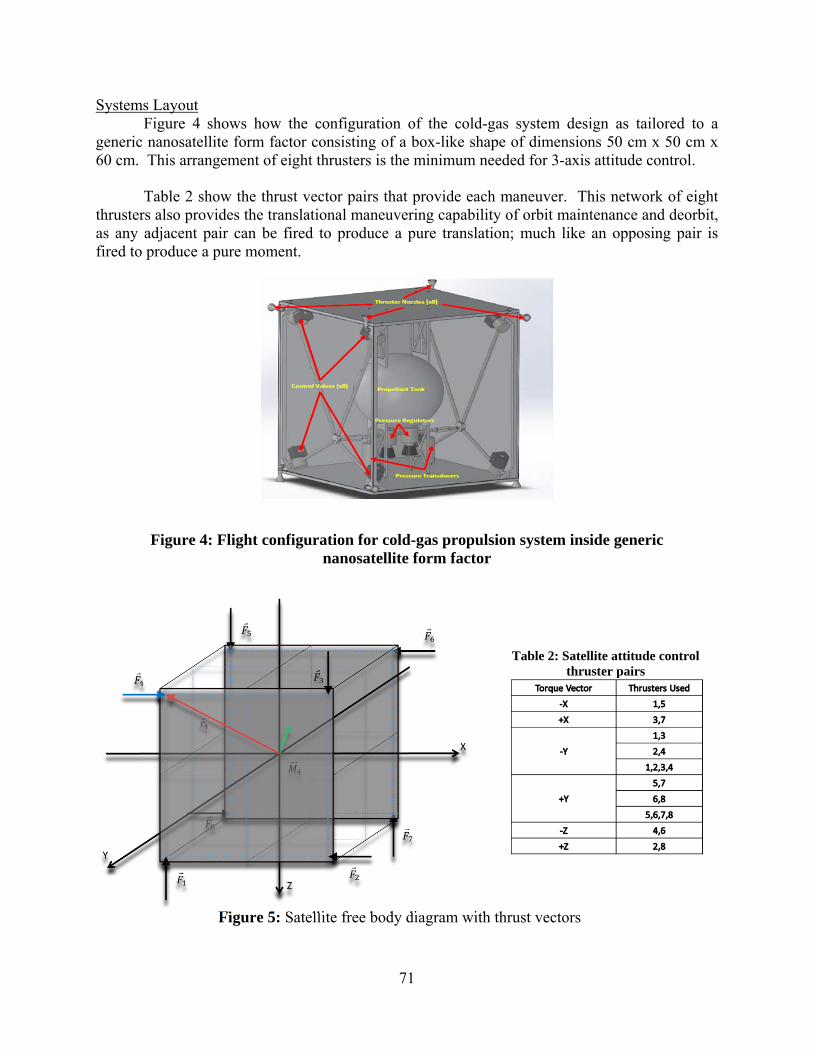
Systems Layout Figure 4 shows how the configuration of the cold-gas system design as tailored to a
generic nanosatellite form factor consisting of a box-like shape of dimensions 50 cm x 50 cm x 60 cm. This arrangement of eight thrusters is the minimum needed for 3-axis attitude control.
Table 2 show the thrust vector pairs that provide each maneuver. This network of eight thrusters also provides the translational maneuvering capability of orbit maintenance and deorbit, as any adjacent pair can be fired to produce a pure translation; much like an opposing pair is fired to produce a pure moment.
Figure 4: Flight configuration for cold-gas propulsion system inside generic nanosatellite form factor
Table 2: Satellite attitude control thruster pairs
Figure 5: Satellite free body diagram with thrust vectors

72
Thruster Nozzle Design Perhaps the most critical design component of the propulsion system is the thruster
nozzle. Using compressible flow fluid dynamics, it can be shown that the most efficient design utilizes a converging-diverging geometry, as this will maximally accelerate the propellant flow through the thruster and optimize the efficiency of the propellant. The design considerations for both the flight and prototype nozzle designs are mentioned below, with the key parameters summarized in Table 3 and Table 4. Flight Nozzle
A flight model nozzle intended to operate in space should theoretically expand the propellant gases until they reach near-vacuum conditions. The area ratio of such a nozzle would be infinity and so is not practical. In reality, it is not desirable to expand the gas until it reaches zero pressure either, due to liquification of the gas at extremely low pressures and temperatures. If the propellant is expanded in the nozzle to this point, the propulsive efficiency will decrease rapidly because the liquid will not flow like a gas or obey accordingly and so all the assumptions we’ve made about the flow up until this point will be invalid. As a result, the nozzle exit pressure and temperature together are now the driving variables in determining the optimal nozzle geometry.
Table 3: Flight nozzle design parameters
Propellant CO2
Inlet pressure 100 psia
Throat diameter 0.125”
Mach number @ exit 4.13
Exit diameter 0.522”
Nozzle area ratio 17.45
Exit velocity 562 m/s
Propellant mass flow rate 0.016 kg/s
Thrust 9.04 N
Table 4: Prototype nozzle design parameters
Propellant Dry Air
Inlet pressure 100 psia
Throat diameter 0.125”
Mach number @ exit 1.80
Exit Diameter 0.150”
Nozzle area ratio 1.44
Exit velocity 485 m/s
Propellant mass flow rate 0.013 kg/s
Thrust 6.20 N
Prototype Nozzle
For prototyping, system parameters that would permit testing in an enclosed area were chosen. This meant using compressed air as a propellant, as it is readily available and cheap, and would not pose an asphyxiation hazard if we vented it in tight quarters. It was assumed the gas would be held at room temperature, as no means of thermal control would be implemented. The outlet pressure of 100 psia was somewhat an arbitrary choice. It was a ballpark estimate that would afford some flexibility in choice of nozzle throat size and thrust, improving manufacturability. Ultimately, other system components were selected based on this pressure choice. Computational Fluid Dynamics
Numeric computer simulations were employed to validate the analytical model used to design the thruster nozzles. ANSYS software was used for this compressible flow simulation. A

73
test geometry identical to the prototype nozzle geometry was modeled, having an inlet and exit diameter of 0.150”, a throat diameter of 0.125”, and a length of 1.432”. The boundary conditions were established to be a no-slip condition along the walls of the nozzle, with an input condition of 100 psia gas pressure, and an exit condition of 14.7 psia. The results of this simulation can be view below. Figure 6 shows the flow velocity profile through the nozzle, and Figure 7 shows the velocity along the centerline of the nozzle.
Figure 6: Velocity profile through
prototype nozzle
Figure 7: Velocity along nozzle centerline
The results from the computational simulations were encouraging in that they matched the analytical predictions both qualitatively and quantitatively. Figure 7 shows that the propellant flow velocity increases along the entire length of the nozzle, hitting sonic velocity at the throat plane and then accelerating to supersonic velocity downstream from there until it reaches the nozzle exit plane. Figure 6 shows the nozzle exit velocity to be 18,351 in/s, about 466.1 m/s, which matches the analytical value shown in Table 4 with 3.9% error, an impressively consistent result. Prototype
Not having the time or resources to fabricate a flight unit propulsion system, the prototyping goal of this design project was a system capable of single-axis control. Successful demonstration of 1-axis control can be extrapolated to 3-axis control, as a 3-axis maneuver can be decomposed into a combination of single-axis maneuvers. Translational orbital maneuvers would not require control validation, and so a system with validated thrust and one-axis control capability would satisfy all design objectives. Manufacturing Approach
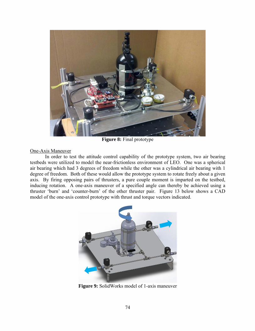
The system-level design approach taken for this project focused on integrating commercial off-the-shelf (COTS) components as much as possible. COTS components procured include a paintball gun tank, a welding tank regulator, instrument-grade stainless steel tubing and fittings, and industrial solenoid valves. Aside from skeletal and mounting hardware, the only custom-designed components were the thruster nozzles. Figure 8 shows the final prototype as assembled and mounted to HSFL’s 3-axis spherical air bearing testbed.
74
Figure 8: Final prototype
One-Axis Maneuver
In order to test the attitude control capability of the prototype system, two air bearing testbeds were utilized to model the near-frictionless environment of LEO. One was a spherical air bearing which had 3 degrees of freedom while the other was a cylindrical air bearing with 1 degree of freedom. Both of these would allow the prototype system to rotate freely about a given axis. By firing opposing pairs of thrusters, a pure couple moment is imparted on the testbed, inducing rotation. A one-axis maneuver of a specified angle can thereby be achieved using a thruster ‘burn’ and ‘counter-burn’ of the other thruster pair. Figure 13 below shows a CAD model of the one-axis control prototype with thrust and torque vectors indicated.
Figure 9: SolidWorks model of 1-axis maneuver

75
A simple method to produce single-axis control for such a rotational maneuver is to employ Equation 3, Newton’s 2nd Law of Motion for rotating bodies, with Equation 4, the kinematic equation for a rotating body.
Equation 3
12
Equation 4
Equation 5
Knowing the mass moment of inertia of the prototype body about the axis of rotation, as
well as the torque supplied by the thrusters, the position of the body as a function of time can be controlled with an open-loop control scheme using prescribed constant values for angular velocity and acceleration. Similarly, knowing the moment of inertia and having an empirical value of angular acceleration, the thrust of each thruster can be measured using Equation 5. Global Test Results
After a solid couple months of performing exhaustive tests of every system parameter I could think of, I was able to characterize the performance of the prototype propulsion system that was fabricated. Using a final test setup on the single-axis air bearing with no added ballast and the closest configuration to the original design intent as possible, with the exception of the inertia, I performed acceleration, inertia, and mass flow rate tests. These allowed me to calculate the individual thruster output, as well as the overall system performance in terms of delta-v. Table 5 summarizes the final prototype as it performed on the last day of testing.
Table 5: Cold-gas prototype characterization
Angular Acceleration 1.329 rad/s2
Inertia 0.68 kg*m2 Torque 0.903 N*m Moment Arm 0.203 m Number of thrusters 2 Thrust 2.224 N Mass flow rate 0.0063 kg/s Nozzle exit velocity 353 m/s Specific impulse 36 s Delta-v 59 m/s
Overall, the maximum thrust generated during testing, 2.2 N, was about one-third of the
6.2 N that I desired and expected from my nozzle design. Additionally, the mass flow rate was about half of what I wanted. Combining these, I calculated a nozzle exit velocity of 353 m/s, which is sonic, but only about 73% of the desired output. The overall system delta-V is similarly 73% of the quantity I designed the system to produce. Additionally, the open-loop control maneuvers performed yielded inconsistent results. Those tests performed on the spherical air bearing testbed were refined to yield about +/- 5° accuracy, while those performed on the cylindrical air bearing generally yielded results no better than +/- 20° accuracy.

76
CONCLUSION
The cold-gas propulsion system design has a solid foundation in place but there is still further analysis and testing required to validate the design. If this is achieved, the design can potentially be submitted for flight qualification. Now that the nozzle design has been prototyped, there is further testing required to close the loop on the design. The first phase of the design, the analytical models of compressible flow, was used to craft the nozzle geometry. The second phase, the computational simulations done using ANSYS CFD software, was used to confirm the first phase to high degree of accuracy. The third and final phase, validation by physical testing, has not yet been achieved.
Extensive testing performed to date has failed to fully achieve the flow parameters desired. After performing many mass flow rate test trials with different setups, it became clear that the solenoid valves being used were restricting the flow substantially, creating a significant pressure drop over the valve. Digging a bit deeper, it was discovered that the original valves were sourced based on pressure rating alone, and had an effective orifice size of 3/64”, which is far smaller than even the thruster nozzle throat which has a diameter of 1/8”. This meant that the valve orifice was acting as the choke point in the flow, not the nozzle throat, and so the system was not behaving appropriately. A new set of larger solenoid valves was sourced and purchased using Hawai‘i Space Grant Fellowship supply funding. These had a larger effective orifice size of 5/32” and a lower pressure rating of 130 psig. This was the best-suited model of solenoid valve that the manufacturer, Parker Fluid Control, produced for this purpose, and so a new set of four of these solenoid valves was procured to replace the originals. Unfortunately, these still restricted the flow more than desired, and even when maxing out the pressure regulator, the pressure drop across the valve was big enough that the output pressure was not high enough to produce choked flow through the prototype nozzle. One way to mitigate this would be to increase the input pressure. However, the pressure regulator purchased could only output 0-150 psig which was not sufficient for the flow rate desired. In retrospect, it would have been simpler and easier to replace the pressure regulator instead of the solenoid valves, but this would still have been a piecemeal solution. Overall, these shortcomings do not appear to be a limitation of the specific system design or cold-gas technology itself, but rather a reality of the prototyping process, showing the inherent difficulty in manifesting something from the drawing board to a real working prototype.
In addition to the limitations of the prototype system, there were several difficulties with creating an ideal test setup. The spherical air bearing testbed worked well for the intended purposes, but the extra degrees of freedom meant present meant that the applied thrust torque vector could move off the axis of rotation, thereby wasting torque and preventing an accurate thrust measurement. In order to remove this variable from the equation, the single-axis cylindrical air bearing was substituted, but this was not without its own issues. The friction in the bearing was much higher, and most troubling, appeared to be very inconsistent. Different maneuvering test results were obtained for different starting positions. A one axis bearing introduces the need to balance the mass of the system much more exactly, in order to ensure the axial load on the bearing is evenly distributed. This is not a concern with the spherical bearing as the testbed can dip and roll in response to an uneven load. In both cases, the air movement in the room played a significant role in the establishment of a “frictionless” test. The friction
77
measured was likely different each time due, in part, to the atmospheric conditions in the room. Additionally, the non-linear friction test results yielded could be consistent with air drag, which is proportional to the square of velocity. Overall, too much time was spent trying to create a frictionless testbed, but in the end, it proved to be impossible. Future testing could be done in a vacuum chamber to attempt to improve the results and isolate the variables sought to measure. Additionally, a linear thrust transducer should be created and used to measure the thrust produced, as this would take the uncertainty of the ‘frictionless’ rotation maneuvers out of the equation, and measure the thrust more directly.
Beyond the shortcomings of the prototype system that have been observed to date, there is additional analytical work needed to finalize the design of the flight unit propulsion system and verify if the design meets all of the specified functional requirements. One thing that would be valuable to evaluate is the thrust/time trade-off for the other orbital maneuvers that are being designed for, namely orbit maintenance and deorbit. This will determine if another thrust magnitude is desirable. A different thrust magnitude would require a different working thruster pressure or nozzle throat area. This would complicate the system further, introducing the need for a regulator that could be adjusted on orbit, or perhaps even an entirely separate set of thrusters. The added plumbing and components for this would likely add substantial mass and complexity to the system, potentially violating the functional requirement relating to system mass, and thereby invalidating the design, and so this course of action will be avoided if possible.
Next, a more accurate way to characterize the delta-v required for attitude control is needed. The method shown above in Figure 2 considers the delta-v needed to turn the spacecraft 180° about any body axis, but this is not a common attitude control maneuver. For many satellite missions, pointing requirements will dictate that the satellite must hold a given attitude over a long period of time, and so the challenge is not to turn or maneuver the craft, but rather to hold it steady. This is more complicated to model.
Another very important improvement needed is closed-loop control. The current open-loop control scheme used has shown its limitations as our single-axis maneuvers were capable of 5° accuracy at best. Better test results than this were attained, but there was certainly a measure of good fortune involved in those. Sensor feedback from an inertial measurement unit would greatly improve the fidelity of the control system and enable the system to provide much more accurate maneuvers. Satellite pointing requirements are generally less than 1° due to the large distance between the satellite and Earth-based target of pointing. At these distances, which even at LEO altitudes are at least 350 km, even pointing errors of less than 1° can create targeting errors of several kilometers.
Finally, estimation of end-of-life performance needs to be carried out. As the propellant is used up, the storage pressure will decrease until it hits a low point at which the pressure regulator will no longer be able to supply the specified output pressure. This means there will invariably be some wasted gas that stays in the system at the end of the operational lifetime. It will be important to accurately estimate this or measure it during testing, so that it can be taken account of in the propellant and delta-v budget used for mission planning.

78
In conclusion, this design project has succeeded in laying the groundwork for a future nanosat mission augmented by propulsive capability. The vision of this technology development project is to implement the principles and models demonstrated on a future iteration of HSFL’s current nanosatellite mission, HiakaSat. My conservative estimation is that another semester or two of undergraduate student work on this project could be sufficient to yield a baseline design framework that could be handed off to HSFL design engineers to implement in a future small satellite project.
ACKNOWLEDGEMENTS
Thanks to my project teammates from ME 481/482 – Evan Greer, Nathan Walsh, and Daniel Wukelic for all of their assistance with the design, fabrication, and testing of this prototype system
Thanks to my mentor and faculty advisor for ME 481/482 – Dr. A. Zachary Trimble, for all of his guidance and support throughout the design process.
Thanks to Dr. Beei-huan Chao for his invaluable expertise and assistance in completing the compressible flow analysis.
Thanks to Dr. Dilmurat Asimov for his assistance with crafting the open-loop control scheme demonstrated through prototype testing.
Thanks to Dr. Weilin Qu for his assistance with pressure-drop measurement test setup for our components, as well as for lending us his tube bending and cutting tools.
Thanks to Windell Jones for lending us his cylindrical air bearing test setup and for helping us figure out the discrepancies we encountered with 1-axis maneuver testing.
Thanks to Aaron Toyama of the COE machine shop for machining our thruster nozzles for us free of charge.
And my warmest mahalo to Mars, Dr. Ed Scott, and everyone else at the HSGC for continuing to support me throughout my undergraduate career here at UH. Your support has been invaluable in helping me achieve my career goals. Mahalo nui loa!
REFERENCES
J. Akagi, "Small Satellites 101: University of Hawaii Small-Satellite Program," in Emergence of Pico- and Nanosatellites for Atmospheric Research and Technology Testing, AIAA Press, 2010.
J. R. Wertz and W. J. Larson, Space Mission Analysis and Design, El Segundo, CA, Microcosm Press, 1999.
U. N. Program, "Other Mission Requirements," in Nanosat-7 User's Guide, Air Force Research Laboratory, 2011.
J. L. Sellers, Understanding Space: An Introduction to Astronautics, New York: McGraw-Hill, 2005.
D. D. Brown, Spacecraft Propulsion, American Institute of Aeronautics and Astronautics, 1996.
L. K. Yoneshige, "Microthruster Propulsion," in The Emergence of Pico- and Nanosatellites for Atmospheric Research and Technology Testing, AIAA Press, 2010.