Embed Size (px)
Citation preview
COKE OVEN AREA SPECIAL STUDY AREA INTERIM MEASURES WORK PLAN PHASE 1
SEVERSTAL SPARROWS POINT, LLC
SPARROWS POINT, MARYLAND
Prepared for:
Severstal Sparrows Point, LLC Sparrows Point, Maryland In accordance with:
United States of America and State of Maryland Department of the Environment v. Bethlehem Steel Corporation; Docket No. JFM-97-558 & JFM-97-559
April 2009
URS Corporation 200 Orchard Ridge Drive Gaithersburg, MD 20878
Page 1 of 8
1.0 INTRODUCTION
This document is the work plan to implement Phase 1 (P1) of interim measures (IM)
intended to address contamination in groundwater and the vadose zone at the Coke Oven
Area (COA) of the Severstal Sparrows Point Facility (Severstal). This P1 IM WP
describes the planned procedures to implement a pilot scale Soil Vapor Extraction/Air
Sparging (SVE/AS) system at the COA, intended to recover COA groundwater and
vadose zone contamination and provide design information for a potential larger scale
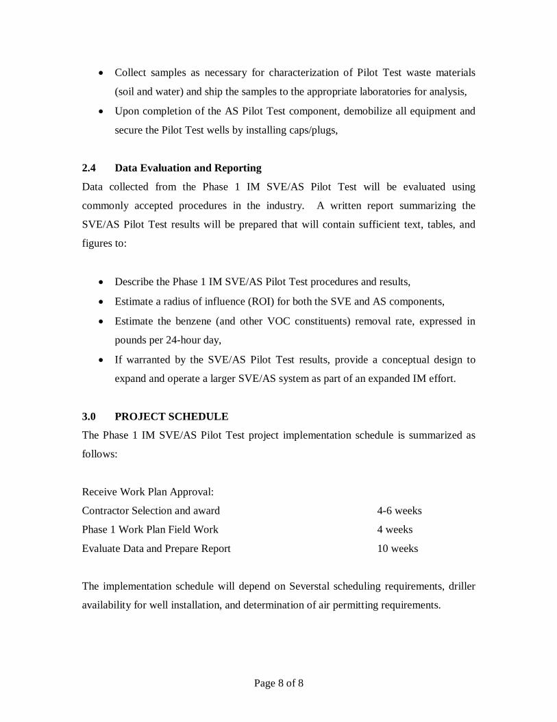
SVE/AS system. Figure 1 illustrates the location of the COA.
This P1 IM WP is intended to comply with the requirement specified in the United States
Environmental Protection Agency (USEPA) letter (dated February 19, 2009) requesting
Severstal to submit to USEPA a work plan to implement interim measures to recover
hydrocarbon product in the COA, under the authorization of United States of America
and State of Maryland Department of the Environment v. Bethlehem Steel Corporation;
Docket No. JFM-97-558 & JFM-97-559. The USEPA letter cites elevated levels of
benzene and naphthalene, both which are addressed in this P1 IM WP.
1.1 OBJECTIVES
The overall objective of this P1 IM WP is to collect further site-specific information
pertaining to technologies that have the potential to protect human health and the
environment and, to the extent practicable, do so in a manner consistent with any
additional Interim Measures or potential long-term corrective action. Specifically, this
P1 IM WP describes a Pilot Test that is intended to:
1. Evaluate the potential effectiveness of SVE/AS technologies for removing and
destroying benzene and naphthalene mass from the unsaturated zone and shallow
groundwater, and
2. Develop criteria for possible expanded-scale IM application if the P1 IM SVE/AS
Pilot Test demonstrates potential effectiveness.
Page 2 of 8
1.2 DESCRIPTION OF SITE AND P1 IM SVE/AS PILOT TEST AREA
The COA is located at the southwestern portion of the Sparrows Point peninsula. The site
is made land comprised of slag placed over the natural materials comprised of: 1) recent
fluvial sediments deposited by Bear Creek/Patapsco River, and 2) underlying clay, silt
and sand layers of moderate density associated with the Talbot Formation.
The Slag-Fill unit is the uppermost hydrostratigraphic unit at the COA. The shallow
water table occurs within the Slag-Fill Unit at a depth on the order of 10 feet below
ground surface. Slag-Fill Unit groundwater is unconfined. In some COA areas, the Slag-
Fill Unit is directly underlain by and connected to the coarser grained beds or lenses
within the Talbot Formation. In these areas, the Slag-Fill and natural permeable materials
form a single groundwater flow system. Throughout much of the COA, the Slag-Fill unit
is underlain by finer-grained silts and clays of the Talbot Formation. In these areas,
groundwater flow in the Slag-Fill Unit is separated from groundwater flow in any
underlying coarse-grained beds or lenses. Shallow groundwater movement at the COA
generally is radial toward surrounding surface water bodies.
COA groundwater analytical results indicate that VOCs and SVOCs (predominately
benzene and naphthalene) have impacted groundwater. The areal extent of the VOCs and
SVOC is confined to the southwestern fill portion of the Sparrows Point peninsula and
has not migrated to the area north of the COA. The maximum VOC concentrations
(predominately benzene) are located at the northwest portion of the COA. Groundwater
with elevated VOCs has migrated toward the southwest and northwest of the Coke Oven
SSA and is present at the shoreline. The SVOC concentrations (predominately
naphthalene) are more evenly distributed, and the maximum concentrations are located
on the eastern half of the Coke Oven SSA. VOC and SVOC concentrations decrease to
below their respective reporting limits or exhibit a significant decreasing trend toward the
laboratory reporting limits in all samples collected from the lower groundwater zone
piezometers.
Page 3 of 8
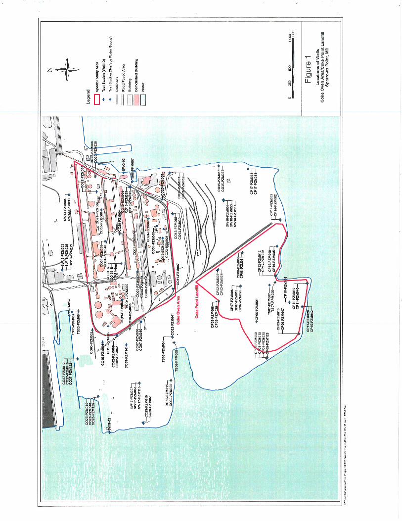
Figure 2 shows the general planned location of the P1 SVE/AS Pilot System test area
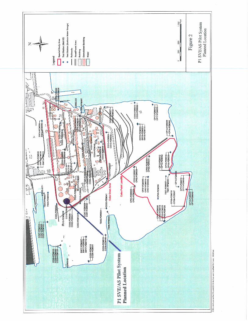
within the COA. This location was selected because, as shown on Figure 3, shallow
groundwater benzene and naphthalene concentrations are elevated here (i.e., 1,300 mg/L
benzene and 0.19 mg/l naphthalene in well CO18). These data suggest that the P1
SVE/AS pilot system could recover benzene and naphthalene vapor mass from the
unsaturated zone and provide design information for a future larger scale system.
2.0 P1 IM SVE/AS PILOT TEST INVESTIGATION PROGRAM
This section describes activities to collect and evaluate further site-specific information
pertaining to the P1 IM SVE/AS Pilot Test technologies.
2.1 Preliminary Considerations
Preliminary considerations for development of the P1 IM SVE/AS Pilot Test focus on
benzene because the benzene concentrations greatly exceed the naphthalene
concentrations. However, the technology and associated considerations also apply to
naphthalene.
Based on the 1,300 mg/L groundwater benzene concentration at well CO18 (Figure 3), an
equilibrium soil gas benzene vapor concentration of 8.9% (89,000 ppmv) is estimated.
Percentage concentrations of benzene in soil gas are unsafe to treat with granular
activated carbon (GAC) prior to discharge to atmosphere because of excessive heat
generated during the exothermic GAC adsorption reactions. Several methods for
extracting and treating the benzene-laden soil gas were considered:
1. Thermal oxidizer (propane-fired) with integral regenerative blower for soil gas
extraction,
2. Catalytic oxidizer (either electrically heated or propane-fired) with integral
regenerative blower for soil gas extraction, or
3. Specially equipped, propane-fueled internal combustion engine (ICE) equipped
with catalytic converter.
Page 4 of 8
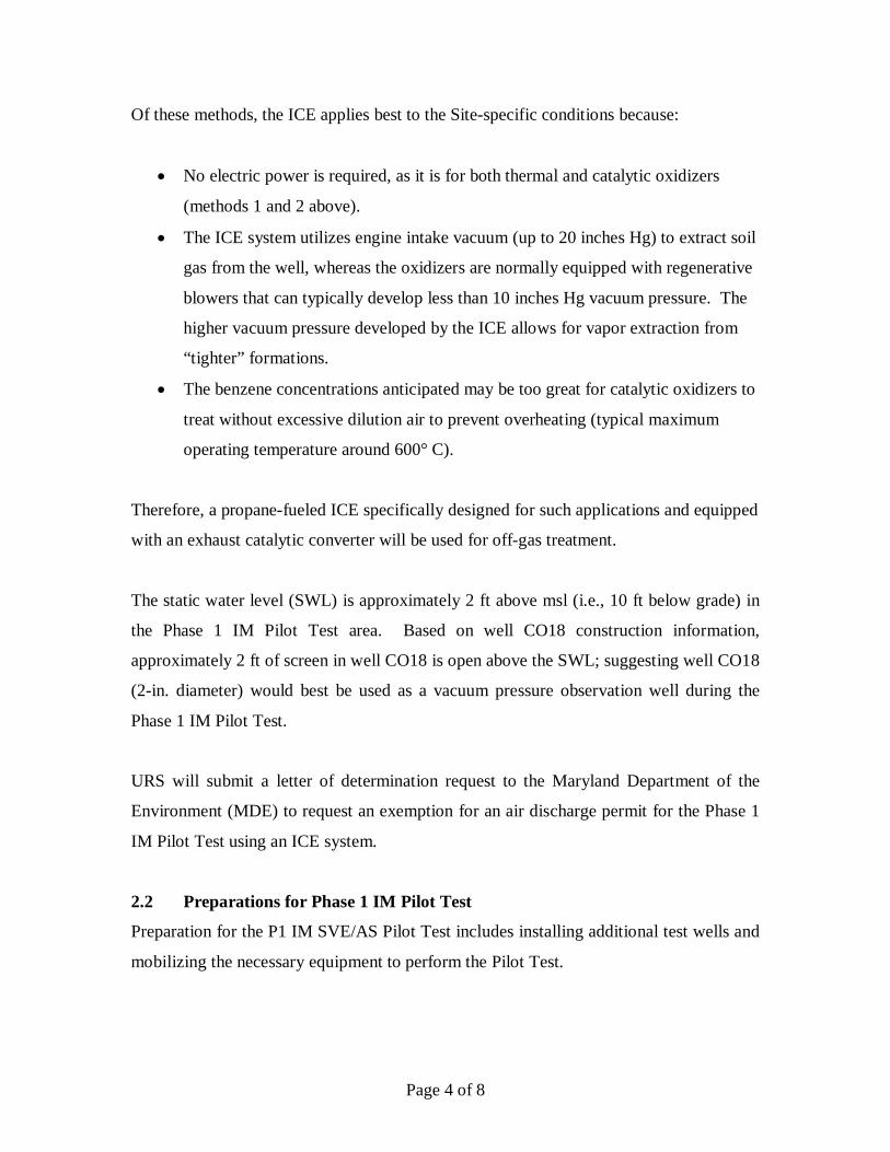
Of these methods, the ICE applies best to the Site-specific conditions because:
• No electric power is required, as it is for both thermal and catalytic oxidizers
(methods 1 and 2 above).
• The ICE system utilizes engine intake vacuum (up to 20 inches Hg) to extract soil
gas from the well, whereas the oxidizers are normally equipped with regenerative
blowers that can typically develop less than 10 inches Hg vacuum pressure. The
higher vacuum pressure developed by the ICE allows for vapor extraction from
“tighter” formations.
• The benzene concentrations anticipated may be too great for catalytic oxidizers to
treat without excessive dilution air to prevent overheating (typical maximum
operating temperature around 600° C).
Therefore, a propane-fueled ICE specifically designed for such applications and equipped
with an exhaust catalytic converter will be used for off-gas treatment.
The static water level (SWL) is approximately 2 ft above msl (i.e., 10 ft below grade) in
the Phase 1 IM Pilot Test area. Based on well CO18 construction information,
approximately 2 ft of screen in well CO18 is open above the SWL; suggesting well CO18
(2-in. diameter) would best be used as a vacuum pressure observation well during the
Phase 1 IM Pilot Test.
URS will submit a letter of determination request to the Maryland Department of the
Environment (MDE) to request an exemption for an air discharge permit for the Phase 1
IM Pilot Test using an ICE system.
2.2 Preparations for Phase 1 IM Pilot Test
Preparation for the P1 IM SVE/AS Pilot Test includes installing additional test wells and
mobilizing the necessary equipment to perform the Pilot Test.
Page 5 of 8
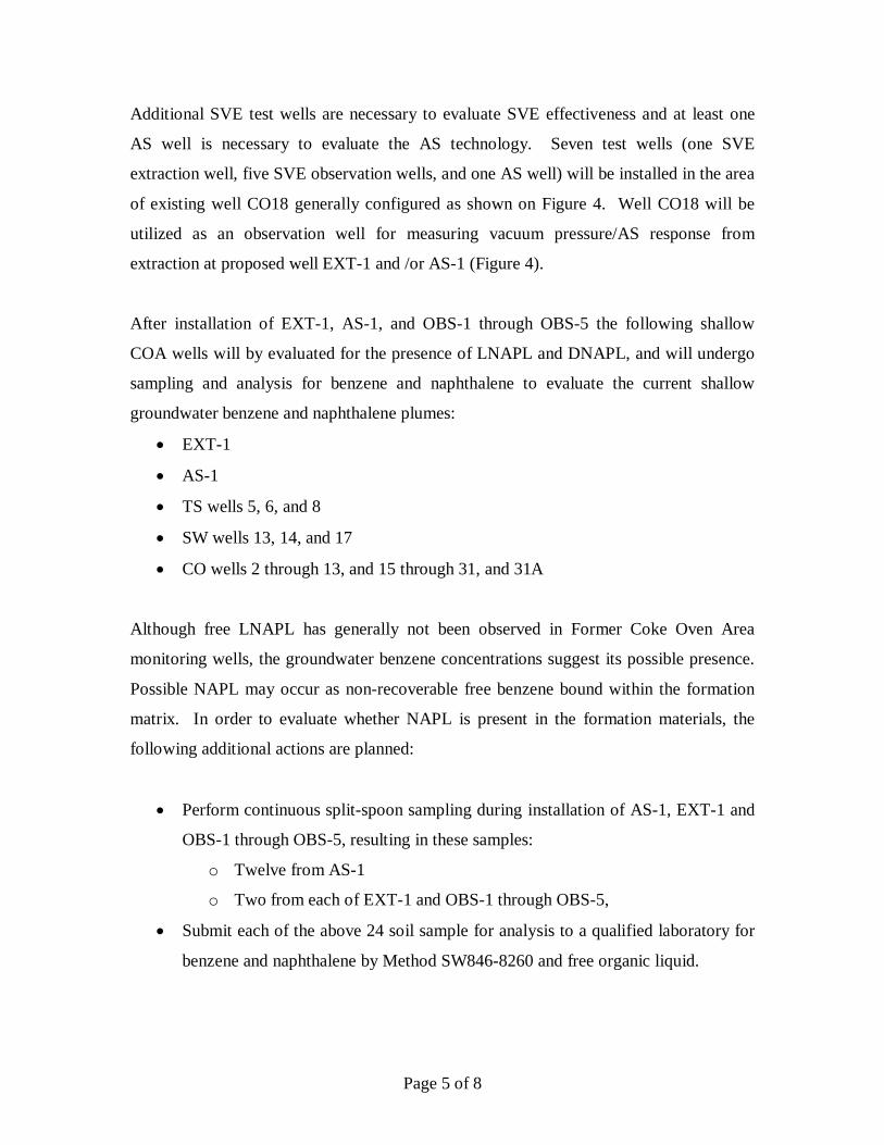
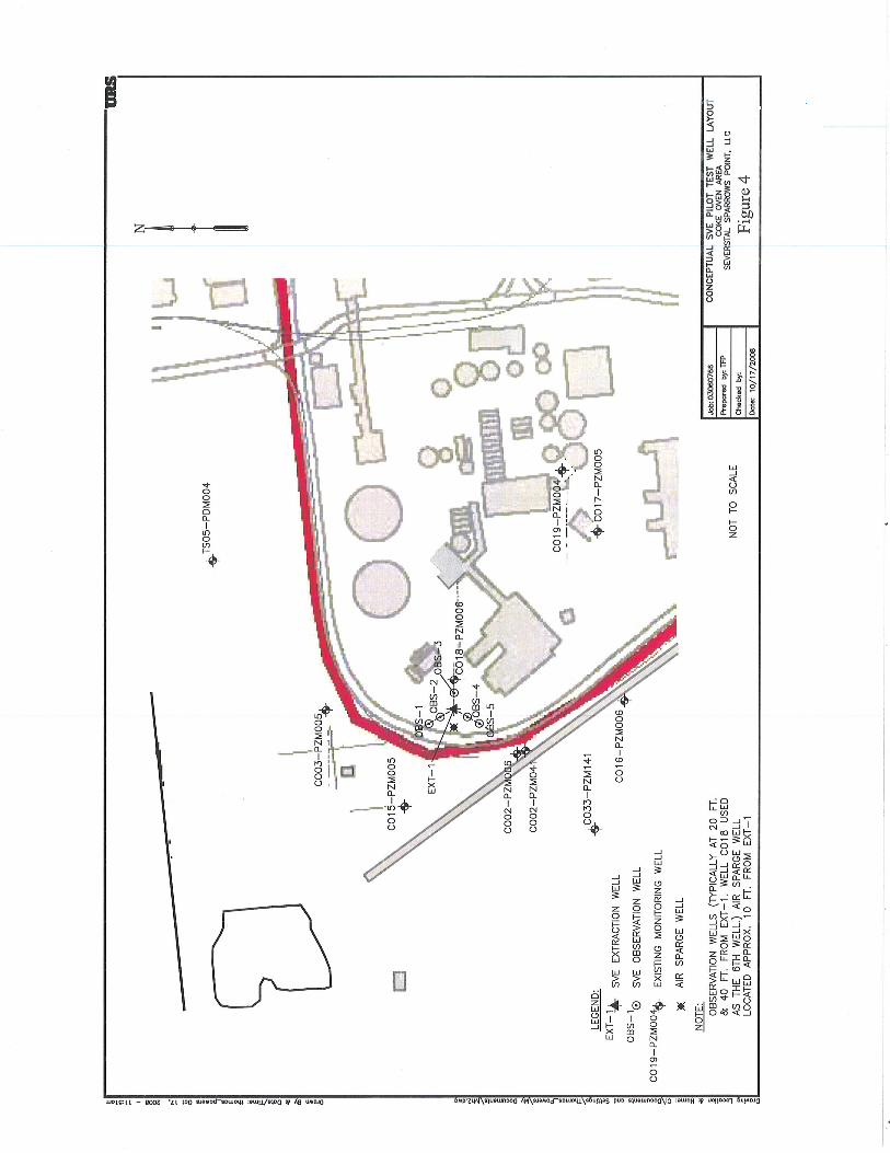
Additional SVE test wells are necessary to evaluate SVE effectiveness and at least one
AS well is necessary to evaluate the AS technology. Seven test wells (one SVE
extraction well, five SVE observation wells, and one AS well) will be installed in the area
of existing well CO18 generally configured as shown on Figure 4. Well CO18 will be
utilized as an observation well for measuring vacuum pressure/AS response from
extraction at proposed well EXT-1 and /or AS-1 (Figure 4).
After installation of EXT-1, AS-1, and OBS-1 through OBS-5 the following shallow
COA wells will by evaluated for the presence of LNAPL and DNAPL, and will undergo
sampling and analysis for benzene and naphthalene to evaluate the current shallow
groundwater benzene and naphthalene plumes:
• EXT-1
• AS-1
• TS wells 5, 6, and 8
• SW wells 13, 14, and 17
• CO wells 2 through 13, and 15 through 31, and 31A
Although free LNAPL has generally not been observed in Former Coke Oven Area
monitoring wells, the groundwater benzene concentrations suggest its possible presence.
Possible NAPL may occur as non-recoverable free benzene bound within the formation
matrix. In order to evaluate whether NAPL is present in the formation materials, the
following additional actions are planned:
• Perform continuous split-spoon sampling during installation of AS-1, EXT-1 and
OBS-1 through OBS-5, resulting in these samples:
o Twelve from AS-1
o Two from each of EXT-1 and OBS-1 through OBS-5,
• Submit each of the above 24 soil sample for analysis to a qualified laboratory for
benzene and naphthalene by Method SW846-8260 and free organic liquid.
Page 6 of 8
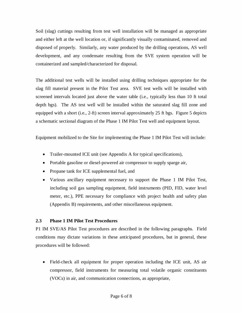
Soil (slag) cuttings resulting from test well installation will be managed as appropriate
and either left at the well location or, if significantly visually contaminated, removed and
disposed of properly. Similarly, any water produced by the drilling operations, AS well
development, and any condensate resulting from the SVE system operation will be
containerized and sampled/characterized for disposal.
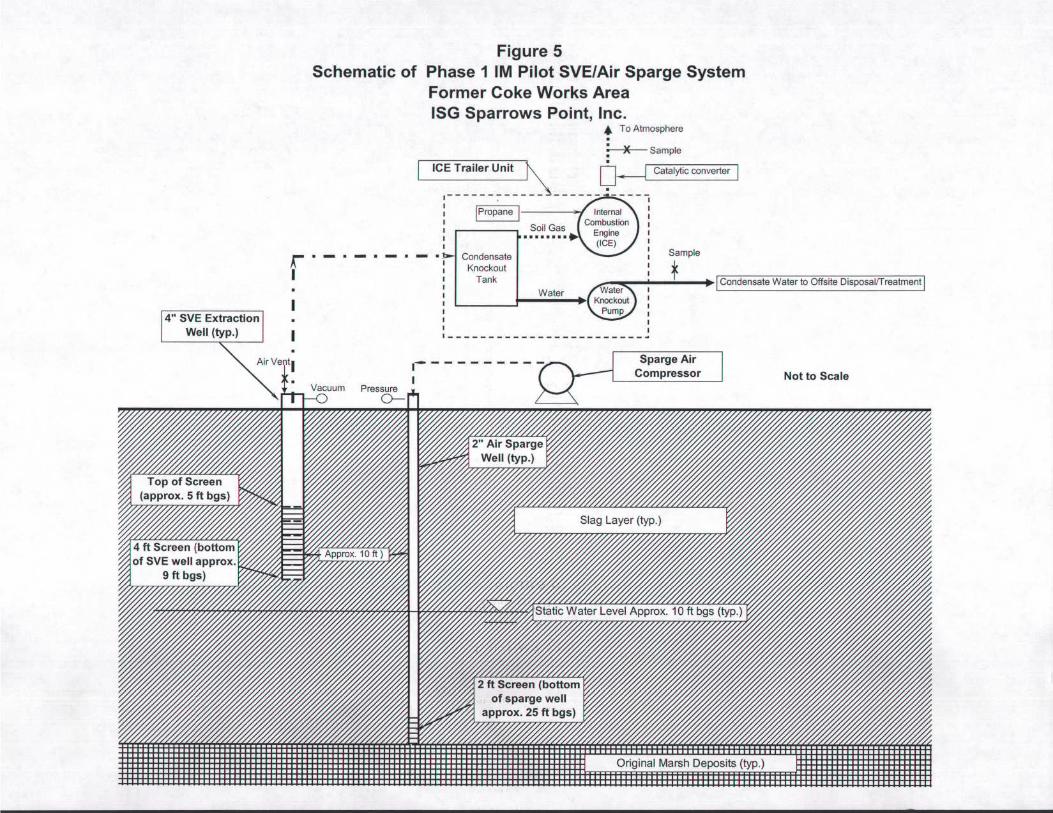
The additional test wells will be installed using drilling techniques appropriate for the
slag fill material present in the Pilot Test area. SVE test wells will be installed with
screened intervals located just above the water table (i.e., typically less than 10 ft total
depth bgs). The AS test well will be installed within the saturated slag fill zone and
equipped with a short (i.e., 2-ft) screen interval approximately 25 ft bgs. Figure 5 depicts
a schematic sectional diagram of the Phase 1 IM Pilot Test well and equipment layout.
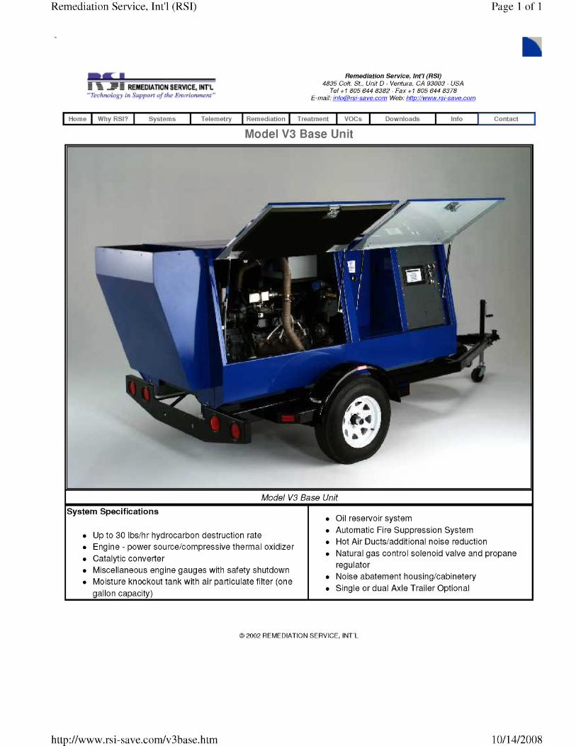
Equipment mobilized to the Site for implementing the Phase 1 IM Pilot Test will include:
• Trailer-mounted ICE unit (see Appendix A for typical specifications),
• Portable gasoline or diesel-powered air compressor to supply sparge air,
• Propane tank for ICE supplemental fuel, and
• Various ancillary equipment necessary to support the Phase 1 IM Pilot Test,
including soil gas sampling equipment, field instruments (PID, FID, water level
meter, etc.), PPE necessary for compliance with project health and safety plan
(Appendix B) requirements, and other miscellaneous equipment.
2.3 Phase 1 IM Pilot Test Procedures
P1 IM SVE/AS Pilot Test procedures are described in the following paragraphs. Field
conditions may dictate variations in these anticipated procedures, but in general, these
procedures will be followed:
• Field-check all equipment for proper operation including the ICE unit, AS air
compressor, field instruments for measuring total volatile organic constituents
(VOCs) in air, and communication connections, as appropriate,
Page 7 of 8
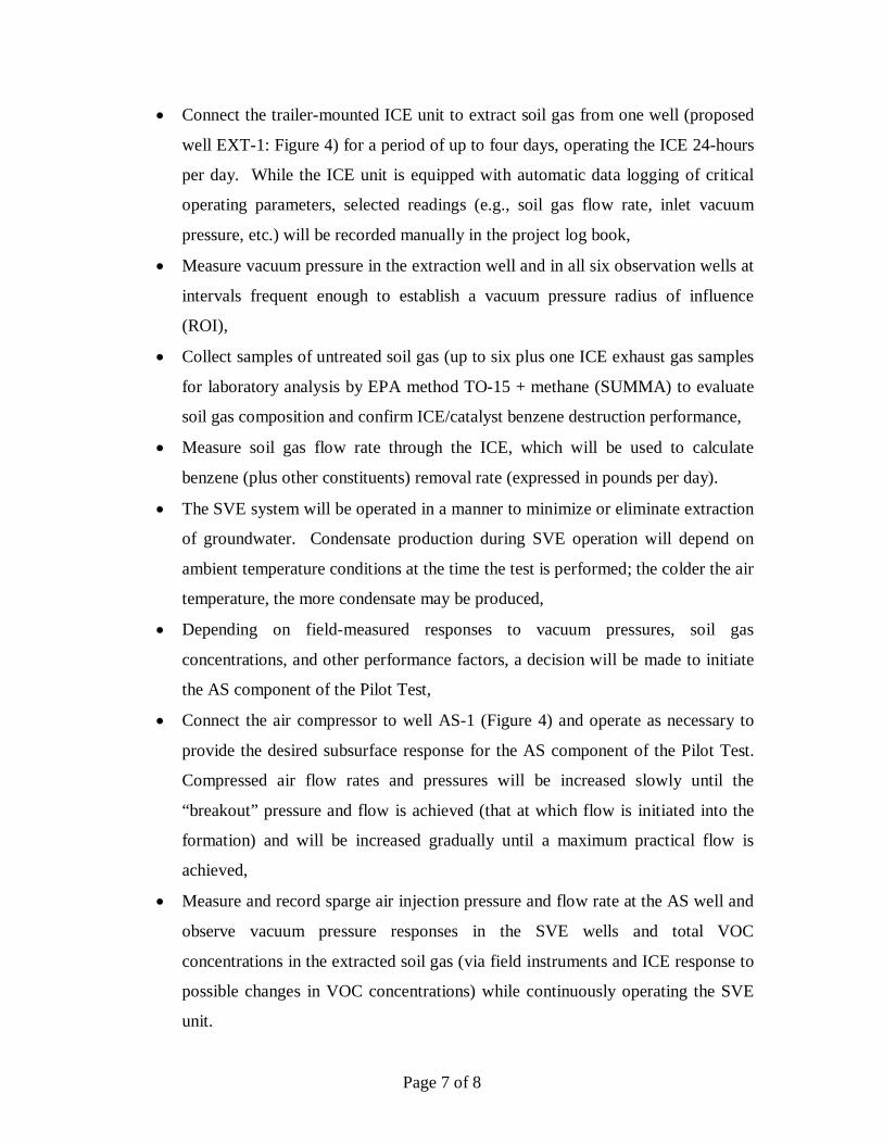
• Connect the trailer-mounted ICE unit to extract soil gas from one well (proposed
well EXT-1: Figure 4) for a period of up to four days, operating the ICE 24-hours
per day. While the ICE unit is equipped with automatic data logging of critical
operating parameters, selected readings (e.g., soil gas flow rate, inlet vacuum
pressure, etc.) will be recorded manually in the project log book,
• Measure vacuum pressure in the extraction well and in all six observation wells at
intervals frequent enough to establish a vacuum pressure radius of influence
(ROI),
• Collect samples of untreated soil gas (up to six plus one ICE exhaust gas samples
for laboratory analysis by EPA method TO-15 + methane (SUMMA) to evaluate
soil gas composition and confirm ICE/catalyst benzene destruction performance,
• Measure soil gas flow rate through the ICE, which will be used to calculate
benzene (plus other constituents) removal rate (expressed in pounds per day).
• The SVE system will be operated in a manner to minimize or eliminate extraction
of groundwater. Condensate production during SVE operation will depend on
ambient temperature conditions at the time the test is performed; the colder the air
temperature, the more condensate may be produced,
• Depending on field-measured responses to vacuum pressures, soil gas
concentrations, and other performance factors, a decision will be made to initiate
the AS component of the Pilot Test,
• Connect the air compressor to well AS-1 (Figure 4) and operate as necessary to
provide the desired subsurface response for the AS component of the Pilot Test.
Compressed air flow rates and pressures will be increased slowly until the
“breakout” pressure and flow is achieved (that at which flow is initiated into the
formation) and will be increased gradually until a maximum practical flow is
achieved,
• Measure and record sparge air injection pressure and flow rate at the AS well and
observe vacuum pressure responses in the SVE wells and total VOC
concentrations in the extracted soil gas (via field instruments and ICE response to
possible changes in VOC concentrations) while continuously operating the SVE
unit.
Page 8 of 8
• Collect samples as necessary for characterization of Pilot Test waste materials
(soil and water) and ship the samples to the appropriate laboratories for analysis,
• Upon completion of the AS Pilot Test component, demobilize all equipment and
secure the Pilot Test wells by installing caps/plugs,
2.4 Data Evaluation and Reporting
Data collected from the Phase 1 IM SVE/AS Pilot Test will be evaluated using
commonly accepted procedures in the industry. A written report summarizing the
SVE/AS Pilot Test results will be prepared that will contain sufficient text, tables, and
figures to:
• Describe the Phase 1 IM SVE/AS Pilot Test procedures and results,
• Estimate a radius of influence (ROI) for both the SVE and AS components,
• Estimate the benzene (and other VOC constituents) removal rate, expressed in
pounds per 24-hour day,
• If warranted by the SVE/AS Pilot Test results, provide a conceptual design to
expand and operate a larger SVE/AS system as part of an expanded IM effort.
3.0 PROJECT SCHEDULE
The Phase 1 IM SVE/AS Pilot Test project implementation schedule is summarized as
follows:
Receive Work Plan Approval:
Contractor Selection and award 4-6 weeks
Phase 1 Work Plan Field Work 4 weeks
Evaluate Data and Prepare Report 10 weeks
The implementation schedule will depend on Severstal scheduling requirements, driller
availability for well installation, and determination of air permitting requirements.

APPENDIX A
RSI Model V3 Base Unit
APPENDIX B
Health & Safety Plan (presented as a separate document)
COKE OVEN AREA SPECIAL STUDY AREA INTERIM MEASURES WORK PLAN HEALTH AND SAFETY PLAN
SEVERSTAL SPARROWS POINT, LLC
SPARROWS POINT, MARYLAND
Prepared for:
Severstal Sparrows Point, LLC Sparrows Point, Maryland In accordance with:
United States of America and State of Maryland Department of the Environment v. Bethlehem Steel Corporation; Docket No. JFM-97-558 & JFM-97-559
April 2009
URS Corporation 200 Orchard Ridge Drive Gaithersburg, MD 20878