Embed Size (px)
Citation preview

MIL
LEN
NIU
M S
TEEL
201
0
144
Coil-to-coil joining with laser welding
The combination of steel strip edge preparation via laser cutting, accurate strip positioning systems, and laser welding in a single unit provides the optimum coil-to-coil joining technology for continuous production plants. With cutting speeds of 20m/min and welding speeds of up to 10m/min, total joining time is typically only 90s for 2mm thick, 1,600mm wide strip.
T he end-to-end joining of coils of strip has grown in popularity over the years as a method of increasing
productivity through continuous operation in many steel processing operations, such as pickling, rolling or galvanising. Initially this was done with welding machines which are integrated into the production lines, using flash-butt welding for thick sheet areas and overlapped welding of thinner sheets. These coil joining methods are, however, considered problematic for processing high-strength Dual phase and Trip steels with tensile strengths of approximately 800N/mm2 and higher.
Laser welding has established itself as a safe and reliable joining process in many applications, including the steels mentioned above, as the steel itself has almost no influence on the process due to the highly concentrated laser beam. Furthermore, with the ever-increasing demands in the market for better coil quality, the demands on the geometry of the welded seam in terms of bumps and depressions in the weld area are also increasing and laser welding has led to an improvement in product quality in this area too.
LASER PROCESSINGA laser (Light Amplification by Stimulated Emission of Radiation) is used as a beam generator to create the energy density required for the welding or cutting process. The laser (usually CO2 or diode for industrial applications) creates a raw energy beam in which the energy is distributed very uniformly across its diameter. This energy density is considerably less than the density required for welding or cutting so the required parameters are obtained by focusing the beam. The required size of the focal point depends on the joint gap between the sheet ends to be welded or the fineness of the cut.
Welding The very high power density of the laser beam – 4MW/cm2 – vapourises the steel and creates a keyhole. This cavity is a high-pressure region surrounded by walls of
Authors: Manfred Neumann and Ralf WallmeyerIDEAL-Werk
r Fig 1 Schematic of the welding process
r Fig 2 Laser cutting/welding head and plasma control
MIL
LEN
NIU
M S
TEEL
201
0
145
a
finishing processes
molten metal. As the beam moves relative to the work piece the molten metal flows backwards around the cavity edges at the trailing edge, forming a narrow fusion zone or weld (see Figure 1). The vapour or plasma formed absorbs laser energy so must be minimised. This is usually done using helium to blow it out of the way, and which also helps prevent oxidation of the liquid steel. The laser beam exit nozzle and gas nozzle are seen in Figure 2. Welding is shown in Figure 3.
Coil joining with a laser beam offers several advantages when compared to the resistance welding process: ` Targeted heat concentration in a small area
(narrow heat affected zone; see Figure 4)` Narrow seam geometries and smooth surfaces` High-strength weld at low seam volume` High process speeds ensure short processing times` The laser beam does not exercise any force on the work
piece and minimises residual stresses and distortion` No consumable electrode needed` No wear of mechanical knives, thus less maintenance
and downtime
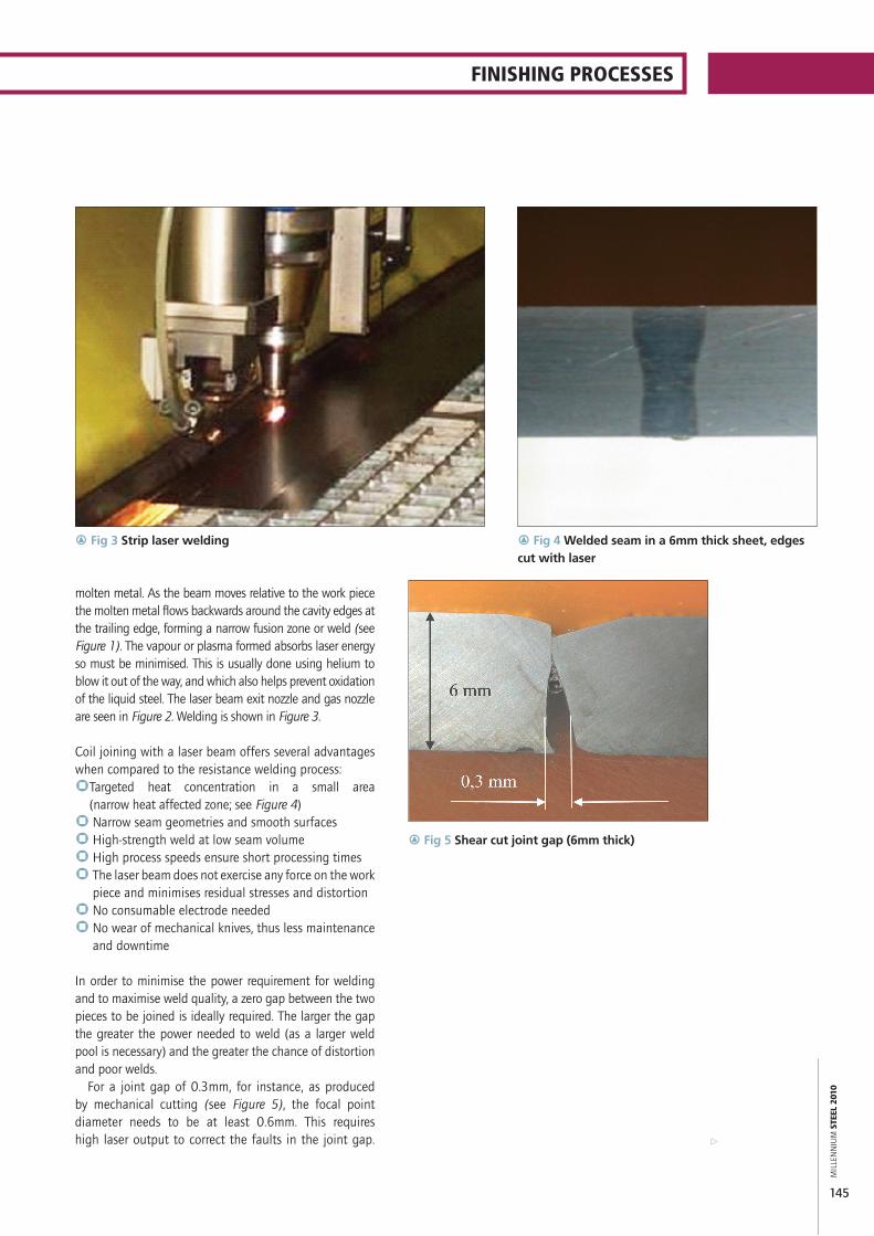
In order to minimise the power requirement for welding and to maximise weld quality, a zero gap between the two pieces to be joined is ideally required. The larger the gap the greater the power needed to weld (as a larger weld pool is necessary) and the greater the chance of distortion and poor welds.
For a joint gap of 0.3mm, for instance, as produced by mechanical cutting (see Figure 5), the focal point diameter needs to be at least 0.6mm. This requires high laser output to correct the faults in the joint gap.
r Fig 3 Strip laser welding r Fig 4 Welded seam in a 6mm thick sheet, edges cut with laser
r Fig 5 Shear cut joint gap (6mm thick)

MIL
LEN
NIU
M S
TEEL
201
0
146
r Fig 6 Laser output as a function of focus diameter
r Fig 7 6mm thick sheet edges cut with laser – zero gap
r Fig 8 Laser cutting
According to Figure 6 this leads to installation of a laser output of approximately 12kW.
A large focal point with the required energy density of approximately 4MW/cm2 is required to join the sheet ends displayed in Figure 4. For a zero gap (Figure 7) the focal point diameter can be 0.2mm diameter and power of only 3.0kW. The optimum preparation for the welding process is a zero gap in which the strip ends lie parallel to each other in the direction of the strip thickness and strip width. Such joints are best produced by a laser cutting system.
Laser cutting Laser cutting is a form of sublimation cutting in which cutting gas is fed coaxially with the laser beam onto the steel surface which blows the vapourised steel out of the keyhole (see Figure 8). Nitrogen is usually used, but in some cases oxygen is preferred.
The transition of the material from solid to gaseous state – sublimation – takes place almost directly, ie, without going through the liquid phase. This gives rise to a vapour capillary which enables deep penetration of the laser beam into the material. The process gas does not only blow out the vapour from the cut joint, it also prevents the condensation of the vapour in the cut joint.
Cutting with laser beam offers several advantages compared to mechanical cutting of strip:` Rectangular cutting edge over the full sheet thickness
and sheet width` Oxidation- and hardness-free cutting edge over the
full width and thickness` Uniform cutting quality and cutting force for all

MIL
LEN
NIU
M S
TEEL
201
0
147
finishing processes
a
material strengths (up to 1,500N/mm2)` No wear and tear because there is no mechanical
contact and only minimal gas on the work piece
COIL TO COIL JOININGThe field of application for a laser coil joining machine requires the processing of: ` Wide range of steel grades` Sheet thickness from 0.3mm to 6.5mm` Sheet widths up to 2,200mm` Sheet tensile strengths up to 1,500N/mm2
` Coated sheets` Sheets with excellent surface quality` Sheets of differing thicknesses
In addition the welded product must exhibit:` No damage on the steel surfaces` The welded seam should not cause any depressions in
neighbouring positions` Several welded seam detection holes can be created
so that the joints can be detected easily and subsequently removed
` Different steel strip widths need to be accommodated. This can be achieved by laser cutting of the wider coil at an angle so there is a smooth transition between coils
The system works as follows. An accumulator provides sufficient storage for the strips to be stopped, positioned, laser cut, repositioned so the two cut faces butt together and then laser welded. The machine does not cut or weld while the coils are moving.
r Fig 10 LAS 300 cutting/welding machine
q Fig 9 LAS 200 cutting/welding machine

finishing processes
A typical cycle time for a 2mm thick and 1,600mm wide strip in an inspection line comes to less than 90s, however this is very much dependant on the installed laser power and processing line requirements. To perform these tasks, IDEAL has developed a range of laser cutting and welding machines which are used in several inspection lines.
IDEAL TYPE LAS 200, FOR USE UP TO 3mm THICKThis type of machine, with a maximum power of approximately 3.5kW, works with an optical lens focusing system and laser beam switching unit – a mirror – between the cutting and welding head (see Figure 9). Thanks to the selected laser cutting machine and the associated good joint gap preparation, these machines can be operated with a focus diameter of approximately 0.2mm, which is adequate to cut and weld 2mm thick strips at speeds of 10 and 20m/min, respectively.
Additional facilities include the production of welding seam recognition holes so that the weld can be readily detected in downstream processing and removed as required, and conventional notching operation using the laser cutting head. This machine type is especially designed to suit the requirements of inspection and slitting lines.
IDEAL TYPE LAS 300, FOR USE UP TO 6.5mm THICK To cut and weld thicker material more power is required. The reinforced model LAS 300 can be operated with a laser power source currently of up to 8kW (see Figure 10). Above ~3.5kW an optical lens cannot be used so this laser has an innovative mirror focusing system. The process tests have yielded excellent welded seam results (see Figure 4). Because of the higher power this model achieves higher cutting and welding speeds. Cycle time has also been reduced by the overlapping of various line and laser welding machine movements.
SUmmARYLaser technology supports the aspirations of strip processors for ever higher productivity and quality by end-to-end joining of coils to provide endless production. The combination of steel strip edge preparation via laser cutting, accurate strip positioning systems, and laser welding in a single unit, provides the optimum coil-to-coil joining technology for continuous production plants. MS
Manfred Neumann and Ralf Wallmeyer are with IDEAL-Werk, Lippstadt, Germany.
CONTACT: [email protected]