Embed Size (px)
Citation preview

Cognitive Interference Management in 4G
Autonomous Femtocells
By
Yangyang Li
A Thesis Submitted in conformity with the requirements for the degree of
Doctor of Philosophy
Department of Electrical and Computer Engineering
University of Toronto
c© Copyright by Yangyang Li 2010

Abstract
Cognitive Interference Management in 4G Autonomous Femtocells
Yangyang Li
Doctor of Philosophy
Department of Electrical and Computer Engineering
University of Toronto
2010
We present a vision for 4G cellular networks based on the concept of autonomous
infrastructure deployment. Cellular base stations, or femtocell access points, are de-
ployed by network users without being constrained by the conventional cell planning
process from the network operator. Autonomous deployment allows the network to
grow in an organic manner which requires new methods for spectrum management.
We study a framework for autonomous network optimization based on the method
of cognitive interference management. In our model, a number of femtocells are
co-channel deployed in an underlay macrocellular network. Instead of fully reusing
ii

Yangyang Li University of Toronto - Electrical and Computer Engineering
100% of the macrocellular resource, partial reuse is cognitively determined in fem-
tocells based on their individual network environment. According to an interference
signature perceived from the environment, a femtocell autonomously determines the
appropriate channel allocation and minimizes the network interference. Upon the
cognitive acquisition of the random infrastructure topology, base station pilot power
is autonomously configured in order to maximize the cellular coverage. A series of
network self-configuration procedures are discussed for automatic cell size adapta-
tion and resource management. Our results show that the new approaches based
on cognitive radio configuration facilitate the network optimization in terms of in-
terference management, mobile handoff, pilot power control and network resource
allocation. The proposed framework offers a 4G vision for spectrum management
in an autonomous self-managed cellular architecture.
iii

Yangyang Li University of Toronto - Electrical and Computer Engineering
To My Fiancee: Yiming Wang
iv

Acknowledgement
I would like to express my sincere gratitude to my advisor professor Elvino S. Sousa
for his offering me the opportunity to study at the University of Toronto. I have
spent four incredible years on my interested research topic under his supervision,
and learned a lot from his unique professional vision and technical insights. I still
remember when we first met in his office, he welcomed me to his ”CDMA Machine
Model” that trains new students to be competent wireless engineers. In the follow-
ing years working with him, I tremendously benefited from his teaching style which
enlightened my mind and shaped my professional character. He introduced me the
right methodology to look at new problems and led me the way of doing independent
research. I feel very fortunate to have worked with professor Sousa in my lifetime
and deeply indebted to his selfless offering through the years.
I would like to thank professor Takuro Sato at Waseda University who offered me
the opportunity to work in Japan and later supported my research publication in
v

Yangyang Li University of Toronto - Electrical and Computer Engineering
Tokyo. I would like to thank my colleagues Paul Soong, Yongjin Wang, Amin Far-
bod, Bruno Korst, Yunfeng Lin and Martin Macuha for their kind assistance and
great friendship. I also would like to thank many of my Chinese immigrant fellows,
who landed in Canada at their middle age yet have been struggling very hard to
rebuild their career. I have been encouraged by their great enthusiasm for life and
strong determination for success.
Finally, I would like to express my gratitude to my parents and fiancee for their
consistent care and support. I dedicate all my work and honors to them.
vi

Contents
Abstract ii
List of Figures xi
List of Tables xii
List of Abbreviations xiii
1 Introduction 1
1.1 Overview . . . . . . . . . . . . . . . . . . . . . . . . . . . . . . . . . . 1
1.2 Autonomous Cellular Architecture . . . . . . . . . . . . . . . . . . . . 7
1.3 Comparison of Two Cellular Concepts . . . . . . . . . . . . . . . . . 9
1.4 Literature Review . . . . . . . . . . . . . . . . . . . . . . . . . . . . . 13
1.5 Thesis Contribution and Organization . . . . . . . . . . . . . . . . . 17
2 Cognitive Interference Management in Autonomous Femtocell Net-
works 21
vii

Yangyang Li University of Toronto - Electrical and Computer Engineering
2.1 Femtocell-to-Macrocell Interference Scenario . . . . . . . . . . . . . . 23
2.1.1 Cognitive Channel Reuse with Orthogonal Channelization . . 23
2.1.2 Analysis of Cognitive Channel Reuse Efficiency . . . . . . . . 31
2.1.3 Cognitive Channel Reuse with Non-orthogonal Channelization 32
2.1.4 Performance Results . . . . . . . . . . . . . . . . . . . . . . . 38
2.1.5 Summary . . . . . . . . . . . . . . . . . . . . . . . . . . . . . 45
2.2 Femtocell-to-Femtocell and Macrocell-to-Femtocell Interference Sce-
narios . . . . . . . . . . . . . . . . . . . . . . . . . . . . . . . . . . . 46
2.2.1 Cognitive Channel Categorization . . . . . . . . . . . . . . . . 47
2.2.2 An Opportunistic Channel Reuse Scheduler . . . . . . . . . . 51
2.2.3 Performance Results . . . . . . . . . . . . . . . . . . . . . . . 56
2.2.4 Summary . . . . . . . . . . . . . . . . . . . . . . . . . . . . . 58
2.3 A Unified View on Cellular Network Optimization . . . . . . . . . . . 59
3 Pilot Power Management in Autonomous Femtocells 63
3.1 Optimization Model for Femtocell Pilot Management . . . . . . . . . 64
3.2 An Autonomous Pilot Management Procedure . . . . . . . . . . . . . 71
3.3 Performance Results . . . . . . . . . . . . . . . . . . . . . . . . . . . 73
3.4 Summary . . . . . . . . . . . . . . . . . . . . . . . . . . . . . . . . . 77
4 A MAC Protocol Design for Autonomous Cellular Resource Allo-
viii

Yangyang Li University of Toronto - Electrical and Computer Engineering
cation 78
4.1 Generic Model for Downlink Power Management . . . . . . . . . . . . 79
4.2 A MAC Protocol Design for Cellular Power Allocation . . . . . . . . 82
4.3 Scheduler Design for Base Stations . . . . . . . . . . . . . . . . . . . 86
4.4 Performance Results . . . . . . . . . . . . . . . . . . . . . . . . . . . 91
4.5 Summary . . . . . . . . . . . . . . . . . . . . . . . . . . . . . . . . . 96
5 Conclusion 97
Bibliography 99
ix

List of Figures
1.1 A Cellular Network . . . . . . . . . . . . . . . . . . . . . . . . . . . . 2
1.2 Two Evolutional Paths to 4G . . . . . . . . . . . . . . . . . . . . . . 6
1.3 Autonomous Cellular Network Topology . . . . . . . . . . . . . . . . 7
1.4 A Generalized Cellular Concept in 4G . . . . . . . . . . . . . . . . . 11
1.5 A Software Dependent Cellular Architecture in 4G . . . . . . . . . . . 12
1.6 A Triple-Play Cellular Industry in 4G . . . . . . . . . . . . . . . . . . 14
1.7 Research Objectives for Autonomous Spectrum Management . . . . . 18
2.1 Autonomous Femtocell Deployment in A Macrocell . . . . . . . . . . 22
2.2 OFDMA Example with Cognitive Channel Reuse . . . . . . . . . . . 26
2.3 Procedure for Cognitive Spectrum Management . . . . . . . . . . . . 28
2.4 Cellular Topology Used in Simulation . . . . . . . . . . . . . . . . . 40
2.5 Public User Channel Outage of {SINR ≤ 5dB} . . . . . . . . . . . . 41
2.6 Public User Channel Outage of {SINR ≤ 8dB} . . . . . . . . . . . . 42
x

Yangyang Li University of Toronto - Electrical and Computer Engineering
2.7 Percentage of Femtocells with Orthogonal Channel Reuse . . . . . . . 44
2.8 Femtocell Downlink Interference in A 3G Macrocell . . . . . . . . . . 47
2.9 Interference Recognition in A 3G Femtocell . . . . . . . . . . . . . . . 49
2.10 Channel Categorization and Reuse Priority . . . . . . . . . . . . . . . 50
2.11 Cognitive Channel Allocation Procedure . . . . . . . . . . . . . . . . 54
2.12 Femtocell Channel SINR Performance . . . . . . . . . . . . . . . . . . 57
3.1 Femtocell Downlink Interference Scenario . . . . . . . . . . . . . . . . 65
3.2 Autonomous BS Pilot Power Update Procedure . . . . . . . . . . . . 71
3.3 Optimized Cell Sizes for Five-Femtocell Deployment . . . . . . . . . . 74
3.4 Optimized Cell Sizes for Ten-Femtocell Deployment . . . . . . . . . . 75
3.5 Variance of Femtocell Coverage in Diameter . . . . . . . . . . . . . . 77
4.1 Three Basic Time Notions . . . . . . . . . . . . . . . . . . . . . . . . 82
4.2 Power Vector Allocation . . . . . . . . . . . . . . . . . . . . . . . . . 83
4.3 Synchronized Power Allocation Vector . . . . . . . . . . . . . . . . . 84
4.4 Autonomous Cellular Resource Allocation Procedure . . . . . . . . . 92
4.5 Average Downlink Frame Error Rate . . . . . . . . . . . . . . . . . . 94
4.6 Average Downlink Transmission Delay . . . . . . . . . . . . . . . . . 95
xi

List of Tables
1.1 Comparison of Two Cellular Concepts . . . . . . . . . . . . . . . . . 10
4.1 Simulation Parameters . . . . . . . . . . . . . . . . . . . . . . . . . . 91
xii

List of Abbreviations
4G the fourth generation of wireless cellular networks
EV-DO Evolution-Data Optimized
HSPA High Speed Packet Access
CDMA Code Division Multiple Access
Wi-Fi Wireless Fidelity
ACM Autonomous Control Module
LTE Long Term Evolution
WiMAX Worldwide Interoperability for Microwave Access
OFDM Orthogonal Frequency-Division Multiplexing
MIMO Multiple-Input and Multiple-Output
IP Internet Protocol
RNC Radio Network Controller
WCDMA Wideband Code Division Multiple Access
UMTS Universal Mobile Telecommunications System
xiii

Yangyang Li University of Toronto - Electrical and Computer Engineering
IKEv2 Internet Key Exchange v2
IPsec IP Security
AMPS Advanced Mobile Phone System
GSM Global System for Mobile communications
CSMA/CA Carrier Sense Multiple Access with Collision Avoidance
OFDMA Orthogonal Frequency-Division Multiple Access
BSC Base Station Controller
TDD Time Division Duplex
FDD Frequency Division Duplex
QoS Quality of Service
SINR Signal to Interference plus Noise Ratio
LP Linear Programming
TD-SCDMA Time Division Synchronous Code Division Multiple Access
MAC Media Access Control
SP Service Period
PB Power Bin
SS Service Slot
BER Bit Error Rate
FER Frame Error Rate
xiv

Chapter 1
Introduction
1.1 Overview
The concept of cellular communication emerged in 1960’s as an extension of the
fixed telecommunication network to the wireless environment. A cellular network
consists of a number of infrastructure base stations deployed throughout a service
area. Each base station serves the mobile users around it as a shared access point
to the backbone network. The service area of a base station is called a cell which
is normally represented by a hexagonal grid. As shown in Figure 1.1, the cells are
generally laid out in a non-overlapping pattern in order to cover a large service area
such as a city or a country.
The cellular concept exploits the fact that the signal power decreases as it prop-
1

Yangyang Li University of Toronto - Electrical and Computer Engineering
Figure 1.1: A Cellular Network
agates in space so that the same frequency carrier can be used in different cells.
This solves the problem of accommodating a large number of users utilizing a lim-
ited block of spectrum. However, frequency reuse in different cells causes mutual
interference in them. To manage this interference, a frequency reuse distance has
to be configured based on the tolerable interference of mobile terminals. A cellular
network has to be deployed according to a rigorous cell planning process performed
by the network operator. Cellular parameters such as frequency reuse distance,
cluster size and channel allocation in a cell need to be jointly configured in order to
produce an optimized network planning strategy [1].
The evolution of the cellular systems has come through three generations over
2

Yangyang Li University of Toronto - Electrical and Computer Engineering
the past 40 years [2]. We have seen the transition from the first generation (1G)
to the second generation (2G) in 1980’s marked by analog communication being
replaced by digital processing technology. Spread-spectrum based communication
emerged in 1990’s and quickly became the dominant standard for the third genera-
tion (3G) technology which significantly improved the voice capacity over 2G. The
recent 3.5G variations such as the Evolution-Data Optimized (EV-DO) and High
Speed Packet Access (HSPA) standards renovated the 3G air interfaces in order to
enhance their data carrying capability. Despite all these fast evolutions of the cellu-
lar technology, the method to deploy and manage a cellular network has remained
somehow constant [2]. Base stations are regularly deployed by a network operator
who uses its professional engineers to manually configure the network operation pa-
rameters. In a 3G Code Division Multiple Access (CDMA) based network, these
parameters invariably include base station pilot power, base station antenna tilting
angle, orientation of the antenna sectors in a cell, pilot neighbour list, pilot sequence
offset in different cells and other operation parameters transmitted in the synchro-
nization channel. The configuration process of these cellular parameters is critical
in optimizing the performance of a cellular network.
We now have an extensive research effort throughout the world targeting the
next generation (the 4th generation or 4G) cellular systems. Except for the obvious
goals for higher bit rate and greater cell capacity improvement, a 4G network is ex-
3

Yangyang Li University of Toronto - Electrical and Computer Engineering
pected to have some different characteristics from the legacy cellular standards [2].
One 4G progression has come up with the idea of having a brand new cellular archi-
tecture that facilitates easier deployment of small base stations for organic cellular
capacity improvement [3]. At the root of this approach is the idea of using small
cells to increase the spectrum reuse density. The concept can be traced back to
the cell splitting strategy proposed in [1] where a macrocell can be equally divided
into multiple N subcells and each of them has the same spectrum as that of the
macrocell. Thus a factor of N times capacity can be achieved in the network. The
concept of microcell or picocell follows the similar idea of utilizing smaller cells for
capacity improvement in high-demand traffic locations such as homes and offices.
Nevertheless, a denser deployment of small cells will complicate the procedure for
network configuration. More cost-effective approaches are required in order to facil-
itate easy deployment of a large number of low-power base stations in future cellular
networks.
A good example of small cell deployment can be seen from the Wi-Fi technology.
Low power access points can be autonomously deployed by network users and each
access point defines a hotspot area with small coverage and high capacity. Mainly
targeting ad hoc interconnection of a group of wireless users, the Wi-Fi standard
was defined in the unlicensed spectrum band without rigorous network optimiza-
tion like the cellular standards. However, some of Wi-Fi’s characteristics including
4

Yangyang Li University of Toronto - Electrical and Computer Engineering
autonomous network deployment has made it quite successful in the marketplace.
A future cellular network demands a new architecture that can facilitate the au-
tonomous deployment of the infrastructure similar to Wi-Fi. Accordingly, novel
methods will be required to enhance the robustness of the cellular air interface in
terms of interference management and network optimization.
A novel method of deploying a cellular network has been introduced in [2], [3]
and [4]. Small cellular base stations, or femtocells, are autonomously deployed by
users in an underlay macrocellular network. An autonomous cellular concept al-
lows the network to grow in an organic manner, which reduces the traditional work
on infrastructure installation, network configuration and maintenance. However,
not following a cell planing procedure, the deployment of the femtocells will cause
non-regularized interference to the macrocell network. Therefore, the work for net-
work optimization and interference management will have to be executed by an
Autonomous Control Module (ACM) which adaptively allows network radio recon-
figuration, power control and resource allocation.
To this end, we propose a dual-path progression of the future wireless technolo-
gies as shown in Figure 1.2. The upper path going through Long Term Evolution
(LTE) and Worldwide Interoperability for Microwave Access (WiMAX) technolo-
gies represents a more or less straightforward evolution based on the current 3G
standards. LTE and WiMAX can raise the cell capacity through a series of efforts
5

Yangyang Li University of Toronto - Electrical and Computer Engineering
1G ~ 3GWireless Standards LTE , WiMax, … 4G
Autonomous CellularArchitecture,Femtocell, …
1980 Now2000 2015 Time
convergenceCellular NetworkIntelligence
Higher CellCapacity
Figure 1.2: Two Evolutional Paths to 4G
such as air interface enhancement (e.g., Orthogonal Frequency-Division Multiplexing
(OFDM) + Multiple-Input and Multiple-Output (MIMO) implementation), wider
bandwidth allocation (e.g., up to 100MHz in LTE-advanced system), and IP-based
architectural modification [5], [6], [7]. The traditional view for cellular spectrum
management remains somehow unchanged and the objective is still to improve the
cell capacity in terms of bits/s/Hz/cell.
The lower path shows a different progression by introducing an autonomous
cellular architecture. The conventional cellular approaches have to be renovated in
order to realize the objective for autonomous spectrum management. For example,
when a large number of femtocells are randomly deployed by users, interference
control has to be performed in an automatic manner based on the recognition of
interference environment in the network. Smart power control and adaptive resource
6

Yangyang Li University of Toronto - Electrical and Computer Engineering
allocation methods are required in order to optimize the network configuration.
Therefore, the improvement of network intelligence becomes the new objective in
an autonomously managed cellular network. We claim that the two evolutionary
paths will converge and define a unified 4G air interface that achieves both high
macrocell capacity in large service areas and smart hotspot management in small
cellular scales.
1.2 Autonomous Cellular Architecture
PSTN
traditionalbackhaul RNC
Internet
DSL, TV Cable, Ethernet, …
Autonomous Control
Module (ACM)
Figure 1.3: Autonomous Cellular Network Topology
An autonomous cellular network is shown in Figure 1.3 which comprises the
7

Yangyang Li University of Toronto - Electrical and Computer Engineering
following network infrastructure elements.
• Large base station: the regular base station deployed by a network operator
with its full engineering capability. Cellular parameters such as frequency reuse
distance, antenna tilting angle and base station pilot power have to be manually
configured to optimize the spectrum management. A group of base stations are
connected to a Radio Network Controller (RNC) which manages network resource
allocation, pilot transmit power and mobile handoff between adjacent cells.
• Small base station/femtocell access point: the small cellular access point au-
tonomously deployed by network users. They can operate either on the same spec-
trum band as the large base stations or on a separate frequency carrier. A femtocell
access point can be easily attached to the Internet backbone through multiple in-
terfaces such as DSL, TV cable, power line and Ethernet [4]. The service area of a
femtocell is illustrated by small ellipse circles in Figure 1.3. The size of the coverage
area depends on the maximum transmit power of a femtocell access point which
normally ranges from 5mW to 100mW according to [8].
• Autonomous control module (ACM): the intelligent control module for au-
tonomous spectrum management and dynamic resource allocation. As shown in
Figure 1.3, an ACM server has control interfaces to both macrocell base stations
and femtocell access points. Through an embedded software algorithm designed by
either manufacturers or third-party network optimizer, ACM automatically config-
8

Yangyang Li University of Toronto - Electrical and Computer Engineering
ures the cellular parameters as if the network can self-manage itself in an autonomous
fashion. The control process may require ACM to recognize the change of the net-
work topology and variation of the traffic distribution in the service area. Current
wireless standards may require certain modification in order to meet a specific net-
work optimization requirement.
In future cellular networks, a user-deployed femtocell access point can be very
simple hardware equipment. The computational complexity resides in ACM which
performs like the brain of the whole network. ACM first collects the network infor-
mation such as the interference power from the individual infrastructure equipment,
and then globally optimizes the configuration of channel assignment, pilot trans-
mit power and antenna pattern for all base stations and access points. Under the
central management of ACM, the entire infrastructure body organically configures
itself and intelligently makes resource allocation to mobile users.
1.3 Comparison of Two Cellular Concepts
The autonomous cellular network differs from the traditional cellular concept in
various aspects such as the way to deploy a network, the method to manage the
interference and the criteria to measure the network performance. The traditional
cellular concept was originally proposed by Bell Labs and designed to serve the
voice users with certain mobility requirement. Therefore, the cellular spectrum was
9

Yangyang Li University of Toronto - Electrical and Computer Engineering
regularly reused in space for continuous service provisioning over a large geographical
area. The conventional objective of cellular coverage extension has led to some
common characteristics over the 1 ∼ 3G cellular standards such as circuit-switched
channelization in a cell, regular cell planning and rigorous network configuration for
interference management.
Traditional Cellular Network
(1-3G)
Autonomous Cellular Network
(4G)
Purpose of Spectrum Reuse cellular coverage extension cellular coverage enhancement
Infrastructure Deployment uniform (by operators) random (by users)
Cell Planning regular adaptive
Power Management constant autonomous
Resource Allocation fixed cognitive
Table 1.1: Comparison of Two Cellular Concepts
In an autonomous cellular network, cellular spectrum is spatially reused in an
organic manner driven by network users. Cellular coverage enhancement becomes
the new objective through autonomous femtocell deployment in the underlay macro-
cell network. In comparison to the traditional cellular concept, more autonomous
and self-management elements are introduced for spectrum management which led
to different network characteristics as shown in Table 1.1. We view an autonomous
cellular network a more general concept compared to the traditional cellular model
10

Yangyang Li University of Toronto - Electrical and Computer Engineering
proposed by Bell Labs. As shown in Figure 1.4, characterized by organic network
growth, ad hoc cellular topology, cognitive resource reuse and autonomous interfer-
ence management, an autonomous cellular concept defines the most modern view
on cellular spectrum reuse and interference management. The Bell Labs’ model
fits in the picture as a subset notion when fixed network parameters are manually
configured by the network operator. In other words, an autonomous cellular net-
work automatically reduces to the traditional cellular concept if the requirement
for random base station deployment becomes less considered in the network. More
autonomous elements will be introduced in future cellular networks with new re-
quirement on network self-management and auto-configuration.
Autonomous Cellular Concept
Bell Lab’s Model
Network Growth - OrganicCellular Topology - Ad HocResource Reuse - CognitiveInterference Control - Autonomous
Fixed & regular cellular parameters
Figure 1.4: A Generalized Cellular Concept in 4G
To this end, the future cellular industry will hopefully take the similar trend as
what we have seen from the computer industry, i.e. the software development gets
11

Yangyang Li University of Toronto - Electrical and Computer Engineering
more separated from the hardware and plays more important roles in determining
the system performance. In Figure 1.5, a software control layer is shown on top
of the hardware infrastructure in a 4G cellular network. Through an open con-
trol interface between the two layers, computer software intelligently optimizes the
network resource allocation and interference management. 4G cellular standards
such as LTE and WiMAX will have an IP-based architecture with less hierarchy
in the backbone network. This facilitates the implementation of cost-effective ap-
proaches for interference management based on software design and modification.
Cellular hardware and software will jointly define an intelligent radio interface for
autonomous mobile access in 4G.
Software
Cellular Hardware Infrastructure
Mobile Users
Open Control Interface
Intelligent Access
4G Cellular Backbone
Figure 1.5: A Software Dependent Cellular Architecture in 4G
Similar to the concept of modern computer technology, the efficiency and ro-
12

Yangyang Li University of Toronto - Electrical and Computer Engineering
bustness of the software will eventually determine the performance of the cellular
hardware infrastructure. In the future, the control software can be written and up-
dated by professional companies according to some specific requirement from the
network operator. As shown in Figure 1.6, a network optimizer will possibly spin
off from the traditional cellular manufacturers and operators as a new business type
in 4G. Rather than the manufacturers vending hardware equipments, a network
optimizer provides advanced software solutions to the network operator. This will
accordingly change the traditional role of a network operator in deploying, manag-
ing and maintaining a cellular network. Network optimization will be treated as an
independent mission in 4G based on an open cellular architecture. The implementa-
tion of the new approaches such as software defined radio, cognitive radio and open
source infrastructure [9] will facilitate the emergence of this new business in 4G era.
1.4 Literature Review
A user-deployed cellular network demands novel methods for spectrum management
and network optimization. Existing research has focused on various issues such as
base station pilot power control, network resource allocation and mobile user hand-
off. All these approaches invariably require some autonomous radio configurability
for network self-management. We take a complete summary of the existing results
categorized by four areas in the following discussion.
13

Yangyang Li University of Toronto - Electrical and Computer Engineering
Equipment Manufacturer
Network Operator
NetworkOptimizer
SpinoffBusiness
HardwareProvider
Software Provider
Feedback for Hardware Updates
Figure 1.6: A Triple-Play Cellular Industry in 4G
• Autonomous Pilot Channel Management - Random deployment of a cellular
network raised the issue of base station pilot power management. In traditional
cellular networks the pilot channel is manually configured by the network operator.
Constant pilot power configuration leads to a uniform mobile association pattern
in each cell. In an autonomous cellular network, the cellular base stations are ran-
domly deployed by customers which requires automatic pilot power management
and adaptive cell size configuration. The work in [3], [10] and [11] discussed a
sleep-pilot scheme to manage the pilot pollution level in an autonomous femtocell
network. Base stations are in sleep mode until there is a wake-up signal received
from a terminal. The base station who received the maximum power will respond to
14

Yangyang Li University of Toronto - Electrical and Computer Engineering
that terminal. Similar work can be found in [12] and [13] where the objective has fo-
cused on maximizing the network coverage in a user-deployed cellular infrastructure
topology.
• Adaptive Spectrum Allocation - The work in [14], [15], [16], [17], [18] and [19]
studied adaptive frequency carrier allocation in order to manage the network in-
terference between the macrocell and femtocells. The common idea is to view the
femtocell network as a secondary tier from the macrocell and orthogonal frequency
channels can be dynamically allocated to the two networks [20] and [21]. The short-
coming of these kind of approaches is the requirement for extra spectrum in handling
the femtocell traffic [22]. So far, co-channel deployment of femtocells in an underlay
cellular network is of the major interest to network operators [8], which makes the
problem of interference management more complicated between the two networks.
• Autonomous Power Management - Co-channel deployment of femtocells in an
underlay cellular network has been studied in [10], [23], [24], [25], [26] and [27]. The
model in [10] considered a maximum number of 300 femtocells randomly deployed
inside a 1000×1000m2 macrocell area. By keeping the femtocell coverage below
20 meters in diameter, the results showed dramatic network capacity improvement
based on the Wideband Code Division Multiple Access (WCDMA) standard. The
work in [28], [29], [30], [31], [32] and [33] continued the study on different power
control strategies. Among them, the work in [28] undertook the most comprehensive
15

Yangyang Li University of Toronto - Electrical and Computer Engineering
study on various types of interference scenarios in a WCDMA network. The results
showed that the downlink interference from the femtocells to macrocellular users is
the most critical problem in comparison to other interference scenarios.
• Mobile Handoff and Access - The work in [11], [34], [35] and [36] evaluated
the mobile handoff performance based on 3G Universal Mobile Telecommunications
System (UMTS) standard. Modified handoff procedures were studied with low sig-
naling overheads in the IP backbone network. Both open access and closed access
solutions were proposed with pros and cons to the network operators. By open ac-
cess, a mobile terminal can access any of the femtocell access points in the network.
In closed access, a femtocell is only used by a certain group of users as private access
equipment. Apparently, the open access better helps absorb the macrocell traffic
while introducing the new problem of billing the visiting users to a femtocell [8],
[37], [38] and [39]. So far, the closed access approach has been widely accepted by
the operators due to the ease of implementation. Meanwhile, a hybrid access mode
allowing both open and closed access is under study in order to balance the benefits
from the two approaches [40].
• Femtocell Security - As femtocells are supposed to be small access points
directly attached to the IP backbone network, security issues arose as a concern in
a user deployed network [41]. Various solutions have been discussed to address this
issue including the implementation of IKEv2 (Internet Key Exchange v2) and the
16

Yangyang Li University of Toronto - Electrical and Computer Engineering
IPsec (IP Security) protocols [42].
In addition to these works mostly accomplished based on the 3G UMTS cellular
standard, research in particular focusing on WiMAX femtocell solutions can be
found in [43], [44], [45] and [46]. A good summary [8] developed a study about the
femtocell’s impact to the future cellular industry from both technical and business
perspectives. The autonomous femtocell deployment has been formally launched as
a beyond 3G solution based on the current UMTS and future LTE-based cellular
standards.
1.5 Thesis Contribution and Organization
In this thesis, we propose a novel framework for femtocell interference management.
Note that femtocell deployment by users is essentially a spectrum reuse procedure
in an underlay macrocellular network. Therefore, how to reuse the spectrum in
order to maximize the spectral efficiency is the fundamental problem to solve. In
the 1∼3G cellular systems, the degrees of spectrum reuse is generally measured by
a single parameter called frequency reuse factor. The value of this factor determines
the spatial separation of the co-channel cells based on the tolerable interference
power on a mobile terminal. The typical values of this factor can be 1, 3, or 7
according to specific cellular standard under consideration (e.g., 1 for CDMA-based
systems). Once the factor is determined it normally remains as a fixed value meeting
17

Yangyang Li University of Toronto - Electrical and Computer Engineering
a particular cell planning requirement.
We study a flexible spectrum reuse scheme for femtocell deployment. The idea
is to have an adaptive channel reuse factor based on the location of the femtocells
within a macrocell. We name the scheme cognitive femtocell in the sense that the
channel reuse pattern is cognitively determined according to each femtocell’s channel
environment. A femtocell recognizes an interference signature from the network
and intelligently reuses the proper channel modes to minimize the interference to
the network. Environment perception and interference recognition are necessary
procedures to facilitate cognitive interference management and resource allocation.
Autonomous Interference Management
Autonomous Environment Perception & Radio
Reconfiguration
Autonomous Resource BalancingAutonomous Pilot Power Control
Autonomous Hand-off Decision
Interference Signature Acquisition
UE Mobility Recognition & Prediction
Infrastructure Topology Acquisition
Global Traffic Distribution
Figure 1.7: Research Objectives for Autonomous Spectrum Management
To this end, we show four objectives of our research in Figure 1.7 based on
18
Yangyang Li University of Toronto - Electrical and Computer Engineering
autonomous environment perception and radio reconfiguration.
1. Based on the acquisition of an interference signature from the network en-
vironment, cognitive interference management is achieved through adaptive
channel assignment and power allocation. (Chapter 2)
2. Based on the recognition of the mobile mobility pattern, autonomous mobile
handoff is carried out between the macrocell and femtocells. (Chapter 2)
3. Based on the infrastructure topology recognition, pilot power of a femtocell
access point is automatically updated by maximizing the femtocell coverage.
(Chapter 3)
4. Based on the acquisition of global traffic distribution in the network, the trans-
mit power of each femtocell is adaptively configured to balance the intercell
resource allocation. A time-domain scheduler is studied achieving resource
balance function in an autonomous cellular network. (Chapter 4)
Chapters 2-4 will layout a framework for cognitive spectrum management in a 4G
autonomous cellular architecture. We will see that the ability of the environment
perception and interference recognition are important cellular characteristics for
future autonomous network deployment and optimization. Network performance in
4G will be not only depending on the capability of hardware equipment but also the
19

Yangyang Li University of Toronto - Electrical and Computer Engineering
robustness of software. This will open a new area for cellular network optimization
based on software development and autonomous radio configuration.
20

Chapter 2
Cognitive Interference
Management in Autonomous
Femtocell Networks
We consider a macrocell with a number of femtocells randomly deployed in it as
shown in Figure 2.1. Each femtocell has a small signal coverage (e.g., 30 ∼ 40 meters
in diameter) determined by the maximum transmit power of the access point. We
assume an open access network where mobile users can get associated with either the
macrocell base station or any femtocell access point depending on their position in
the area. Based on the pilot capturing effect, mobiles that are geographically close
to a femtocell have greater chance to be served as femtocell users. Mobiles that are
21
Yangyang Li University of Toronto - Electrical and Computer Engineering
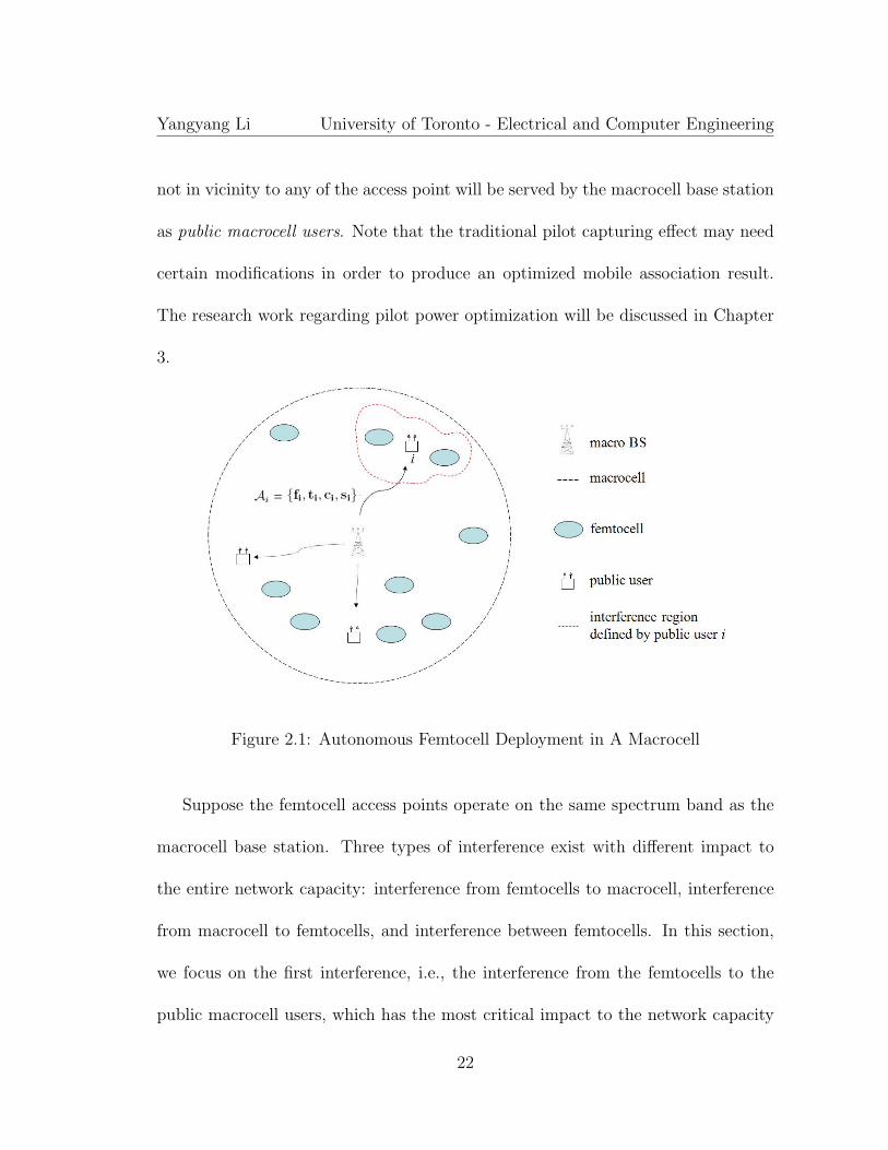
not in vicinity to any of the access point will be served by the macrocell base station
as public macrocell users. Note that the traditional pilot capturing effect may need
certain modifications in order to produce an optimized mobile association result.
The research work regarding pilot power optimization will be discussed in Chapter
3.
Figure 2.1: Autonomous Femtocell Deployment in A Macrocell
Suppose the femtocell access points operate on the same spectrum band as the
macrocell base station. Three types of interference exist with different impact to
the entire network capacity: interference from femtocells to macrocell, interference
from macrocell to femtocells, and interference between femtocells. In this section,
we focus on the first interference, i.e., the interference from the femtocells to the
public macrocell users, which has the most critical impact to the network capacity
22

Yangyang Li University of Toronto - Electrical and Computer Engineering
as analyzed in work [28]. The reason is because the public users are normally far
away from the macrocell base station and thus vulnerable to the local interference
from the close-by femtocells.
2.1 Femtocell-to-Macrocell Interference Scenario
In this section, we study a novel framework of cognitive channel reuse which effec-
tively minimizes femtocells’ interference to public macrocell users. The idea is to
view user-deployed femtocells as a secondary-tier system which autonomously reuses
the orthogonal channels to the primary users in macrocell. Section 2.2 will continue
to extend the framework in dealing with the other two interference scenarios. All
discussion will be focused on downlink communication in the network.
2.1.1 Cognitive Channel Reuse with Orthogonal Channel-
ization
We propose an interference management framework based on a cognitive channel
reuse strategy. The target is to minimize the femtocells’ interference to the public
users. In Figure 2.1, a number of public users are represented as the interference ob-
jects to the user-deployed femtocells. When a public user i is served by the macrocell
base station, the femtocells in its vicinity are viewed as potential interferers.
23

Yangyang Li University of Toronto - Electrical and Computer Engineering
We first review the legacy method to manage the interference between users
within a traditional macrocell. In systems such as Advanced Mobile Phone System
(AMPS), Global System for Mobile communications (GSM) or CDMA, the cellular
resource is channelized in a certain manner and assigned to different users within a
common cell. We denote the downlink channel allocation to a particular user i as
Ai = {fi, ti, ci, si} as shown in Figure 2.1, where Ai represents a particular channel
allocation pattern for user i over four possible channel dimensions - frequency, time,
code and space. Here each element in {fi, ti, ci, si} can be viewed as a vector that
represents the channel allocation metric on the corresponding channel space. The
joint use of these vectors will define a channel pattern for users based on specific
cellular standard. In a GSM system for example, the resource pattern AGSM = {f,
t} produces a two-dimensional frequency × time allocation matrix for voice users.
In a UMTS High-Speed Downlink Packet Access (HSDPA) system, resources are
allocated in three channel dimensions over AHSDPA = {t, c, s} provided that the
antenna sectorization is also applied to the system. Along with the modern advance
of the cellular technologies, cellular channel allocation is getting more flexible over
multiple resource dimensions. In general, a particular channelization pattern Ai has
to be unique for user i, and for a different user j 6= i, we have the classic orthogonal
channelization process from the base station to multiple users in the same cell:
24

Yangyang Li University of Toronto - Electrical and Computer Engineering
Ai ⊥ Aj (2.1)
Now when a femtocell m is deployed in the same macrocell, it is supposed to reuse
some of the macrocellular channels and treat them with proper power allocation.
Now that a femtocell is of very low power, its downlink power only interferes to the
close-by public users (red dashed line area in Figure 2.1). Our solution is to enable
a femtocell to recognize those public users within a certain interference range and
autonomously create an orthogonal channel pattern Rm such that:
Rm ⊥ Ai (2.2)
The above procedure is similar to (2.1) except that it must be executed on
each femtocell in an autonomous manner. The reusable channel pattern Rm on a
femtocell m represents those resource modes that are orthogonal to channel Ai of
the public user i. Unless for some random channel access technology like the Carrier
Sense Multiple Access with Collision Avoidance (CSMA/CA), a channel pattern Ai
can be found as a dedicated channel metric assigned to user i by the macrocell base
station. Therefore, by performing the channelization in (2.2) a femtocell can totally
avoid its interference to the close-by public users.
Here, the key point is the method to get the channel pattern Ai on which the
public user i will be interfered by femtocells. Normally this information is managed
25
Yangyang Li University of Toronto - Electrical and Computer Engineering
by RNC in a 3G network who takes charge of channel allocation in macrocells. A
femtocell can query RNC through ACM for the knowledge of Ai and then treat it
as an interference signature which indicates the channel modes being used by the
macrocell user i. Note that a particular femtocell m does not necessarily need to
query for all public users’ channel information. Instead, a femtocell access point
m should first perceive its environment and recognize the public users within a
certain interference range (Figure 2.1). Then the channelization process of (2.2) can
be implemented based on the acquired interference signature of the close-by public
users. A detailed procedure for interference recognition will be discussed in later
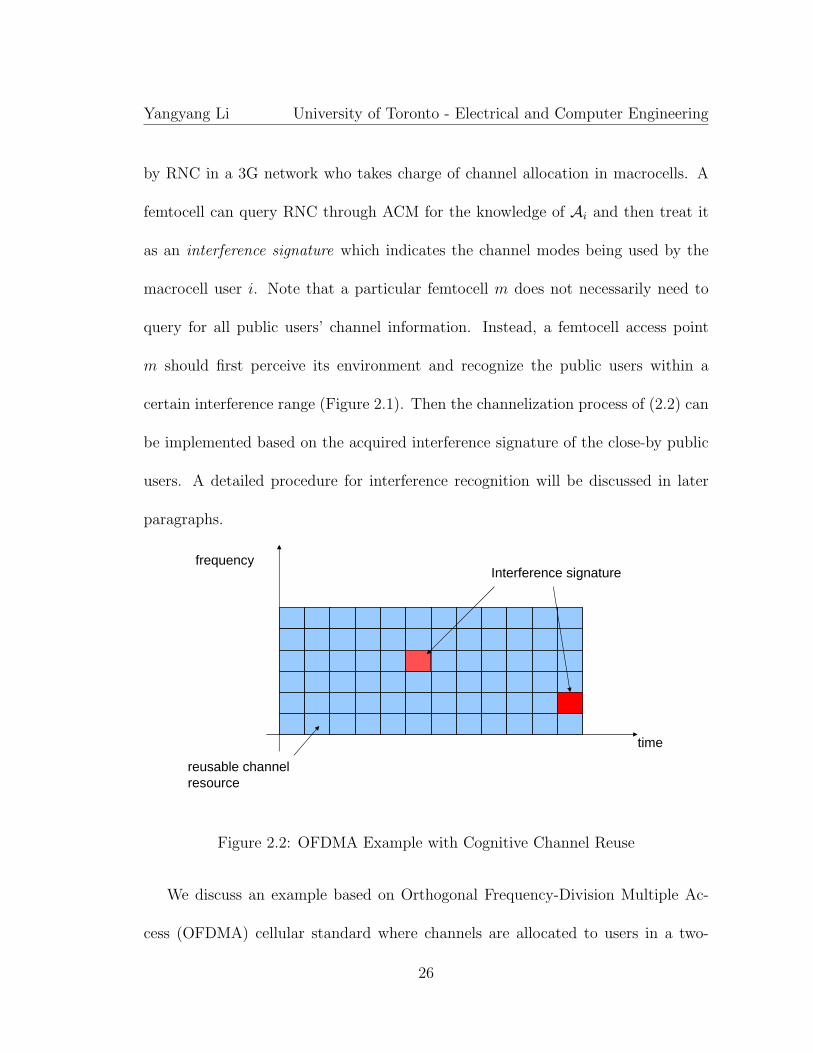
paragraphs.
frequency
time
Interference signature
reusable channelresource
Figure 2.2: OFDMA Example with Cognitive Channel Reuse
We discuss an example based on Orthogonal Frequency-Division Multiple Ac-
cess (OFDMA) cellular standard where channels are allocated to users in a two-
26

Yangyang Li University of Toronto - Electrical and Computer Engineering
dimensional time × frequency matrix. We show such a channel matrix managed by
a femtocell in Figure 2.2 in which the interference signature is illustrated by two
red grids. Based on this recognition of the environment, all the orthogonal channels
(the dark blue grids) can be safely reused in the femtocell without causing interfer-
ence to the public users. One can view this scenario in a way that two public users
i and j are both in vicinity to the femtocell of interest. Due to different distance
to the femtocell, their interference signatures are marked with different strength on
the corresponding channel mode (dark red v.s. light red grids). Ai and Aj are both
unique channel patterns for the corresponding public user, which can be respectively
identified by the femtocell access point. Note that because the public users are gen-
erally distributed in a macrocellular area, the chance for all of them getting close to
a particular femtocell is a very low probability event. In other words, the scheme
will not have to sacrifice a lot channels in a femtocell while effectively avoiding the
interference to the public network. Therefore, the interference management from
femtocell to macrocell is achieved in a geographically distributed manner based on
each femtocell’s individual radio environment.
The procedure for interference signature acquisition plays a critical role for the
above cognitive radio configuration. The way to determine a correct interference
signature varies depending on the specific cellular standards under consideration.
Figure 2.3 shows an example procedure based on OFDMA by having femtocells pe-
27

Yangyang Li University of Toronto - Electrical and Computer Engineering
1. Uplink Radio Environment Listening
2. Uplink Interference Signature Recognition
5a. Cognitive Resource Reuse
3. Query for Interferer’s ID through Control Server
4. Downlink Resource Signature Acquisition
5b. Autonomous Handoff Decision
Figure 2.3: Procedure for Cognitive Spectrum Management
riodically listen to their uplink radios (step 1). Since public users normally have
strong transmission power in uplink in order to communicate with the base station,
a close-by femtocell access point can easily overhear this signal and mark the cor-
responding channel as an uplink interference signature (step 2). According to this
uplink signature information, the femtocell can query ACM for the user IDs of these
public users (step 3). Knowing the ID information, the next step is to acquire the
downlink channel allocation patterns Ai’s that have been allocated to these public
users by the macrocell base station (step 4). Every once in a while, a femtocell should
re-sense the environment and update the downlink signature record due to mobility
28

Yangyang Li University of Toronto - Electrical and Computer Engineering
of the public users. By constantly maintaining a complete environment characteri-
zation, a femtocell cognitively reuses the orthogonal channel modes and adaptively
avoids the interference to the macrocell network (step 5a). The maintenance of the
interference signature matrix also helps recognize the mobility characteristics of the
close-by public users, which assists the mobile handoffs between the macrocell and
femtocell (step 5b).
The above procedure requires a query process from femtocells to ACM in the
infrastructure backbone network. This may cause a time delay up to hundreds
of milliseconds till the signature information is returned to the femtocell. When
the backbone network is based on the Internet Protocol (IP), a round-trip query
process may cause even longer delay due to the process of network queueing, IP
packet encapsulation and decapsulation. Therefore, the scheme is supposed to be
considered for slow/shadow fading level of channelization. This is the similar case in
the traditional 2G/3G cellular networks where slow channelization in each macro-
cell is managed by the Base Station Controller (BSC)/(RNC) in the infrastructure
network.
Here we have introduced a novel cellular feature for autonomous interference
management: radio cognitivity. This concept is related to the cognitive radio concept
that a terminal is able to cognitively sense the available frequency channels and
opportunistically access the spectrum band [47], [48], [49]. The difference is that
29

Yangyang Li University of Toronto - Electrical and Computer Engineering
we have proposed a more comprehensive radio configuring capability over frequency,
time, code and space. When a strong interference signature is perceived from the
environment, a femtocell should perform an orthogonal channelization process to
protect it. A factor, gs, is introduced as the threshold to facilitate this procedure.
Femtocells who perceive a channel gain bigger than gs from a public user should
automatically perform orthogonal channelization on the corresponding signature
mode. Otherwise, the femtocell can safely reuse the signature channel. The value
of gs actually determines the radio sensitivity of a femtocell. The lower the value is,
the more sensitive a femtocell behaves to its network environment and thus lower
interference is generated to the public macrocell users. The network performance
determined by various configurations of gs will be studied in Section 2.1.4.
In a Time Division Duplex (TDD) system, the perceived uplink channel gain
gs from a public user contains the identical information for downlink, which can be
directly used to characterize the interference signature. In a Frequency Division Du-
plex (FDD) system, the uplink gain from a public user can be only used as a rough
channel characterization for downlink. However, the proposed scheme is supposed
to be functioning in a slow/shadow fading channel environment and the key point is
to recognize the physical existence of the close-by public users as described in Fig-
ure 2.3. In this sense, a channel recognition procedure based on uplink environment
listening is enough for cognitive channel configuration (Section 2.1.4). The precise
30

Yangyang Li University of Toronto - Electrical and Computer Engineering
downlink channel gain to public users will be required when we develop the network
capacity analysis in Section 2.1.3.
2.1.2 Analysis of Cognitive Channel Reuse Efficiency
The idea of cognitive channel reuse based on orthogonal channelization is to have
each femtocell recognize the macrocellular interferers and cognitively avoid to reuse
the same channels marked as an interference signature. In other words, a partial
number of channels have to be sacrificed in a femtocell as long as some public users
happen to be close by. It is necessary to study the average percentage of reusable
channels in a femtocell - channel reuse efficiency. A femtocell is not supposed to
lose too many channels due to the orthogonal channelization to public users in the
macrocell.
We suppose that Np and Nf are the number of public users and femtocells within
a macrocellular area. For each public user i, a number of hi channels are allocated
by the macrocell base station. According to a specific sensitivity threshold gs, a
certain interference range will be determined with Ni femtocells being involved for
orthogonal channelization (e.g., Ni = 2 in Figure 2.1). Because each of the Ni
femtocells will have to lose a number of hi channels in order to protect the public
user i, the aggregate loss of the femtocell channels in a macrocell can be written as:
31

Yangyang Li University of Toronto - Electrical and Computer Engineering
hloss =
Np∑i=1
hi ·Ni (2.3)
Now suppose that the same number of total channels H are reused in both
macrocell and femtocells, then a channel reuse efficiency parameter ε can be found
as:
ε = 1− hloss
H ·Nf
= 1−∑Np
i=1 hi ·Ni
H ·Nf
(2.4)
ε represents the average percentage of reusable channels in a femtocell. Because
the aggregate loss of femtocell channels hloss is bounded by the total number of
femtocell channels H · Nf in a macrocell, we have: ε ≤ 1. Note that a lower
value of gs, i.e. better femtocell sensitivity and thus bigger Ni, can lead to a lower
efficiency of ε. In Section 2.1.4 we will study different configuration settings of the
femtocell sensitivity threshold gs and their impact to the channel reuse efficiency ε
of femtocells.
2.1.3 Cognitive Channel Reuse with Non-orthogonal Chan-
nelization
In this section, we take a deeper study for non-orthogonal channel reuse in femtocells.
The objective is to take extra capacity gain on the perceived interference signature
as long as the power allocation can be appropriately optimized on those signature
32

Yangyang Li University of Toronto - Electrical and Computer Engineering
channels. In other words, we study a framework that achieves a two-fold target. One
is the primary objective to manage the interference from the femtocells to the public
network, the other is to maximize the femtocell capacity under the achievement of
the first objective.
Again, we use Figure 2.1 as the cellular layout where femtocells generate interfer-
ence to the public network. Suppose that a public user i defines a public interference
signature Ai and a total number of M femtocells are within the interference region
determined by gs. Instead of having orthogonal channelization in each of these
M femtocells as discussed before, we want to find an optimized power allocation
p∗ = (p1, p2, ..., pM) on Ai for each femtocell m = 1, 2, ...,M , such that:
maxM∑
m=1
Cm (2.5)
s.t.M∑
m=1
hm · pm ≤ P, m = 1, 2, ...,M
The objective is to maximize the sum capacity Cm of the M femtocells on the
common interference signature Ai. P works as an interference threshold that strictly
limits the aggregate interference from the femtocells to the public user i. Here, P
can be viewed as a Quality of Service (QoS) parameter that defines the maximum
tolerable interference for sustaining a specific service for the public user i. The
coefficient of hm is the channel gain from the mth femtocell to the target public user
i. According to the previous discussion, hm can be easily obtained in a TDD system
33

Yangyang Li University of Toronto - Electrical and Computer Engineering
by uplink radio listening on a femtocell access point. In an FDD system, public
users are required to listen the downlink channel and feedback hm to the backbone
network.
The cell capacity of a femtocell m is defined in the following according to Shan-
non’s channel capacity equation [50]:
Cm = rAi· log2(1 +
gm · pm
NAi,m + σAi,m
), (2.6)
where gm denotes the channel gain from the access point m to a single user in the
femtocell. rAidenotes the total resource degrees of freedom on channel mode Ai.
As discussed before, the resource degrees of freedom can be measured based on a
joint allocation of multiple channel modes over frequency, time, code and space. As
for a particular cellular technology, the degrees of freedom allocated to a user is a
fixed pattern over a certain period of time (e.g., a few milliseconds for data and
several minutes for voice services). NAi,m and σAi,m denote the received noise and
the aggregate interference power on the mobile receiver in femtocell m. The vector
p = (p1, p2, ..., pM) is the variable for optimization.
The interference factor σAi,m is treated as noise in the capacity equation because
of a unique channel characteristic in femtocells. Femtocells are normally deployed in
closed indoor areas with good signal protection by walls and floors. Femtocell users
are physically well covered by their own cell appeared as a hotspot area. Therefore,
34

Yangyang Li University of Toronto - Electrical and Computer Engineering
users being served by a femtocell are generally guaranteed with very high Signal
to Interference plus Noise Ratio (SINR) channels, and thus we can assume that
the interference between two femtocells is treated as noise [10]. The summation of
the noise-like interference power from a large number of femtocells is assumed to
be a Gaussian variable with the variance of σAi,m. A more theoretical proof about
treating interference as noise in low interference regime can be found in the recent
work [51].
Note that the above capacity equation (2.6) can be written in a more general
form when time-varying function of each coefficient is considered, i.e.:
Cm(t) = rAi(t) · log2(1 +
gm(t) · pm(t)
NAi,m(t) + σAi,m(t)) (2.7)
Each coefficient can be replaced by a function of time t and the characteristic of
each may vary over different time scales. In our discussion, we focus on the capacity
optimization problem over a certain period of time (e.g., a couple of ms) during
which none of those parameters get significant change in time. The optimization
algorithm can be performed from one time block to next when the parameters are
changing to a different state. Therefore we can safely remove the time index t and
use equation (2.6) for calculating a femtocell capacity over a particular signature
Ai.
In addition, by considering the variable vector p ≥ 0 and safely dropping rAi,
35

Yangyang Li University of Toronto - Electrical and Computer Engineering
we finally have the following optimization problem to solve:
maxM∑
m=1
log2(1 +gm · pm
NAi,m + σAi,m
) (2.8)
s.t.
M∑m=1
hm · pm ≤ P, m = 1, 2, ...,M
pm ≥ 0, m = 1, 2, ...,M
The above formulation strictly constrains the maximum interference from the
femtocells to a public user i who has been allocated with channel Ai by the macrocell
base station. All the M femtocells inside the interference range should rigorously
optimize their transmit power by (2.8) when they reuse the channel modeAi. All the
others channels that are orthogonal to Ai can be freely reused without interference
to the public users as studied in Section 2.1.1.
We write the Lagrangian of the above problem in the following:
L(p, λ, µ) = −M∑
m=1
log2(1 +gm · pm
NAi,m + σAi,m
)
+λ(M∑
m=1
hm · pm − P ) +M∑
m=1
µm(−pm), (2.9)
where λ and µm are Lagrangian multipliers and λ ≥ 0, µm ≥ 0, m = 1, 2, ...,M . The
optimal power allocation satisfies the Kuhn-Tucker condition:
∂L(p, λ, µ)
∂p=
−1
1 + gmpm
NAi,m+σAi,m
· gm
NAi,m + σAi,m
+ λ · hm − µm = 0 (2.10)
36

Yangyang Li University of Toronto - Electrical and Computer Engineering
Solving the above equation yields:
pm +NAi,m + σAi,m
gm
=1
λ · hm − µm
(2.11)
By defining x+ := max(x, 0), the optimal power allocation:
pm∗ = [
1
λ · hm
− NAi,m + σAi,m
gm
]+ (2.12)
The above solution produces very important results for channel reuse in a fem-
tocell. First, not all of the femtocells can reuse the interference signature per-
ceived from their local environment. Those who have the reusing privilege must
satisfy the condition of hm · NAi,m+σAi,m
gm≤ 1/λ. As to the femtocells appearing as
hm ·NAi,m+σAi,m
gm≥ 1/λ, no positive power should be applied from the capacity op-
timization point of view. Here, the product of the interference factor hm and the
weighted noise factorNAi,m+σAi,m
gmjointly characterizes a specific network environ-
ment for a particular femtocell m. One femtocell should cognitively behave itself
based on this environment characterization and accordingly allocate the transmit
power determined by (2.12).
The procedure of an optimal power allocation follows a modified water-filling al-
gorithm. Here the traditional common water level 1/λ for all water-filling channels
is weighted by an extra interference metric hm. The difference between (1/hm) · 1/λ
and the weighted noise termNAi,m+σAi,m
gmin each femtocell defines the optimized
37

Yangyang Li University of Toronto - Electrical and Computer Engineering
power for allocation. Note that hm, m = 1, 2, ...,M represents the interference gain
from a femtocell m to the public user i, which characterizes a femtocell’s interfer-
ence environment. A bigger value of hm means more significant interference to a
public user, which leads to a less power allocation according to (2.12). This perspec-
tive is similar to the traditional water-filling algorithm where a fixed power volume
is poured on multiple channels based on the individual’s SNR condition. In our
solution, the two parameters of noise and interference matric characterize the full
channel information for capacity optimization. One thing to note is that the noise
factor normally behaves as a statistical network parameter without changing too
much from one femtocell to another. Therefore the interference metric hm plays
a much more important role in determining the optimal power allocation in fem-
tocells. This well fits our intuition because the physical location of the femtocells
which gives the interference gain hm acts as a critical factor in determining the
interference power to public users.
2.1.4 Performance Results
We simulate the interference control performance with the following system param-
eters. A two-level piecewise path loss model (in dB) is used in the simulation to
capture the femtocell-to-macrocell signal propagation effect [52]:
38

Yangyang Li University of Toronto - Electrical and Computer Engineering
L(d) =
L1 + γ1log10(d) d ≤ d1
L1 + γ1log10(d1) + L2 + γ2log10(d− d1) d > d1,
and the outdoor macrocell path loss model is characterized by the following:
L(d) = L3 + γ2log10(d),
where d1 = 15m is the average indoor signal propagation distance. The correspond-
ing path loss exponent γ1 = 25 and L1 = 40dB. For the distance bigger than 15m,
we use L2 = 20dB to capture the signal loss by wall attenuation and γ2 = 40 as
the outdoor path loss exponent. L3 = 30dB. In our simulation, an extra Lognormal
variable is added to the path loss model which captures the shadowing fading effect
in the network. The deviations of this variable are respectively set to 4dB within
the macrocell and 10dB from femtocells to macrocell.
Based on the above model, we layout a cellular network with a macrocell radius
of 500m in the center and six surrounding ones as neighbouring cells with regular
cell planning as shown in Figure 2.4. We suppose a frequency reuse factor of 1,
which is the general case for 3G CDMA and WiMAX systems. We now randomly
deploy a number of femtocells in each macrocell and want to study the channel SINR
variation of the public users. In our simulation, we suppose that each femtocell has
a maximum transmit power of 100mW and the macro base station implements a
39

Yangyang Li University of Toronto - Electrical and Computer Engineering
500
250
0
- 250
- 500
- 750
750
1000
- 1000
- 750 7500
Figure 2.4: Cellular Topology Used in Simulation
maximum power of 200mW to serve each public user.
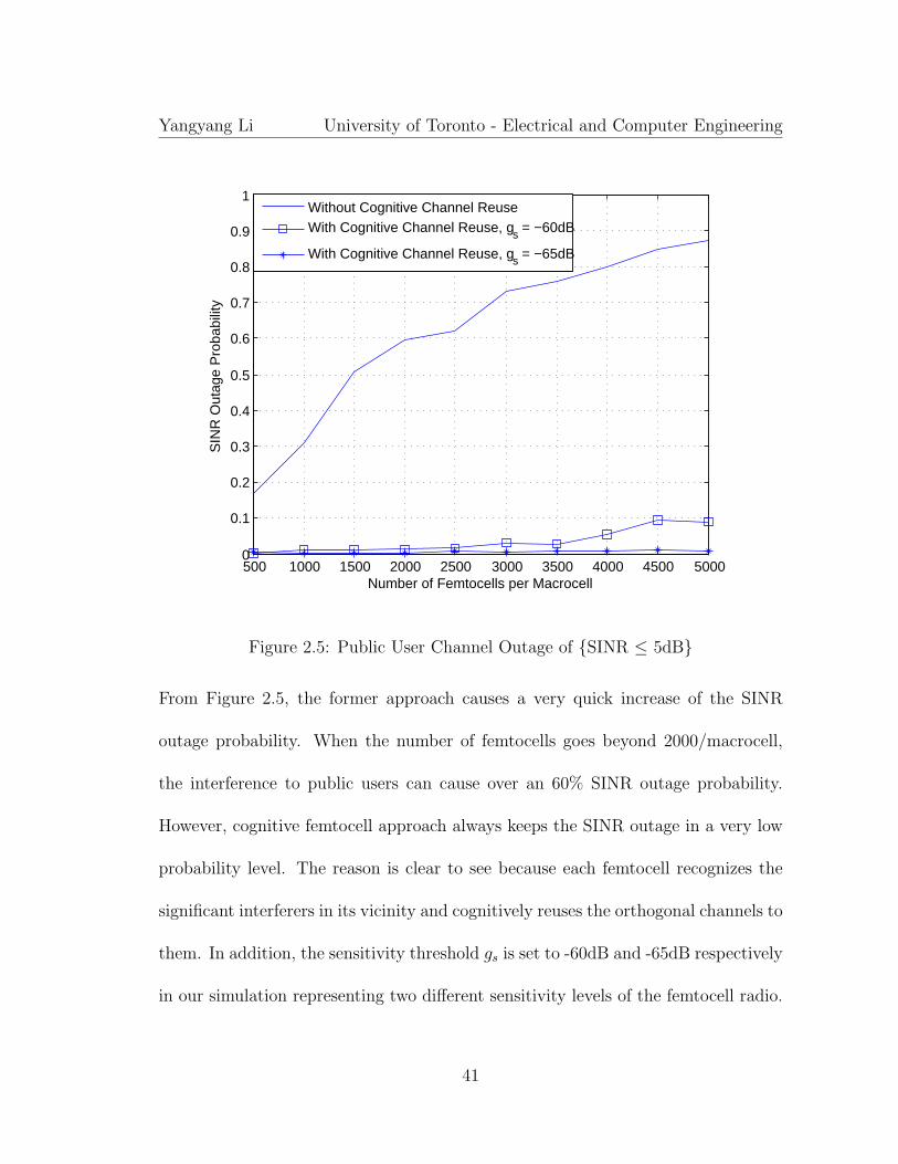
Figure 2.5 shows the SINR outage probability of a public user versus an increas-
ing number of the femtocell deployment from 500 to 5000 in one macrocell. The
SINR outage probability is defined as the relative frequency of the occurring events
{SINR ≤ 5dB} out of 10000 experiments when a public user is randomly positioned
in the center macrocell. We compare the performance of two approaches: one is to
randomly reuse all cellular channels in femtocells without interference recognition;
the other is to implement our method of cognitive channel reuse with orthogonality.
40
Yangyang Li University of Toronto - Electrical and Computer Engineering
500 1000 1500 2000 2500 3000 3500 4000 4500 50000
0.1
0.2
0.3
0.4
0.5
0.6
0.7
0.8
0.9
1
Number of Femtocells per Macrocell
SIN
R O
utag
e P
roba
bilit
y
Without Cognitive Channel ReuseWith Cognitive Channel Reuse, gs = −60dB
With Cognitive Channel Reuse, gs = −65dB
Figure 2.5: Public User Channel Outage of {SINR ≤ 5dB}
From Figure 2.5, the former approach causes a very quick increase of the SINR
outage probability. When the number of femtocells goes beyond 2000/macrocell,
the interference to public users can cause over an 60% SINR outage probability.
However, cognitive femtocell approach always keeps the SINR outage in a very low
probability level. The reason is clear to see because each femtocell recognizes the
significant interferers in its vicinity and cognitively reuses the orthogonal channels to
them. In addition, the sensitivity threshold gs is set to -60dB and -65dB respectively
in our simulation representing two different sensitivity levels of the femtocell radio.
41

Yangyang Li University of Toronto - Electrical and Computer Engineering
One can see that by configuring a 5dB higher sensitivity on femtocells even lower
SINR outage probability is achieved because more public users can be recognized
for interference avoidance.
500 1000 1500 2000 2500 3000 3500 4000 4500 50000
0.1
0.2
0.3
0.4
0.5
0.6
0.7
0.8
0.9
1
Number of Femtocells per Macrocell
SIN
R O
utag
e P
roba
bilit
y
Without Cognitive Channel ReuseWith Cognitive Channel Reuse, gs = −60dB
With Cognitive Channel Reuse, gs = −65dB
Figure 2.6: Public User Channel Outage of {SINR ≤ 8dB}
Figure 2.6 shows the public user outage performance when the channel {SINR
≤ 8dB}. Both of the approaches get severer channel outage for maintaining a 3dB
stronger channel condition. However, by having a higher radio sensitivity by gs = -
65dB the SINR outage can still be well maintained in a low probability level (≤ 7%).
Again this is because each public user has announced a bigger interference range and
42

Yangyang Li University of Toronto - Electrical and Computer Engineering
thus more femtocells in the range cognitively reuse the orthogonal channels to the
local environment. In practice, the performance of a public user such call dropping
probability can be adaptively improved by simply tuning gs parameter of femtocells
to a smaller value. In the following discussion we take a deeper look at the method
of setting a proper sensitivity threshold gs for femtocell configuration.
As what we discussed before, each public user announces an interference range
within which the femtocells have to perform orthogonal channel reuse. The size
of the range is determined by the value of gs. For each public user, a certain
number of surrounding femtocells will have to sacrifice one channel for orthogonal
channelization. A smaller value of gs indicates a wider interference range and thus
a bigger percentage of femtocells will be involved for a channel loss.
We can see in Figure 2.7 that as the sensitivity threshold gs is getting smaller
from -52dB to -70dB this percentage increases from around 5% to 55%. As to gs
= -60dB for example, one public user can cause 18% femtocells in one macrocell
to lose one channel. Now we consider a dense deployment of 5000 femtocells per
macrocell and 100 public users in the same area, then according to equation (2.3)
the total number of femtocell channels sacrificed for cognitive channel reuse are:
100× 5000× 0.18 = 9× 10⁴
We further suppose that the total number of cellular channels H is 200 for both
43

Yangyang Li University of Toronto - Electrical and Computer Engineering
−70 −68 −66 −64 −62 −60 −58 −56 −54 −520
10
20
30
40
50
60
Sensitivity Threshold gs (dB)Fem
toce
ll P
erce
ntag
e w
ith O
rtho
gona
l Cha
nnel
Reu
se (
%)
(−60dB, 18%)
Figure 2.7: Percentage of Femtocells with Orthogonal Channel Reuse
the macrocell and femtocells. This can be viewed as a 2G cellular case such as
CDMA IS-95 system which has 64 voice channels per sector and three sectors per
macrocell. Then the total amount of femtocell channels per macrocell is:
5000× 200 = 1× 10⁶
Now according to equation (2.4), we can easily find the average capacity loss per
femtocell due to the cognitive channel reuse with gs = -60dB:
(9× 10⁴)÷ (1× 10⁶) = 9%
and the channel reuse efficiency ε = 1− 9% = 91%.
44

Yangyang Li University of Toronto - Electrical and Computer Engineering
The above result implicates a very important conclusion about our cognitive
channel reuse approach. By releasing a minor femtocell resource with cognitive
radio configuration, the interference to public users can be efficiently reduced to a
very low level. In our case study with gs = -60dB, the SINR outage probability
for 5dB case is well achieved below 10% even with a very dense deployment of the
femtocells - 5000/macrocell. The average capacity sacrificed in each femtocell is
only 9%. Note that a 9% channel loss is not a big deal in a femtocell because it
normally serves a small number of users (e.g., 1 ∼ 4) and the channels are not likely
to be fully used. In other words, a femtocell normally manages abundant amount
of cellular channels and the key is how to use them in a proper way. To this end,
our results offered an effective solution based on cognitive channel reusing. When
femtocells are randomly deployed inside an underlay macrocell, they autonomously
manage their interference to the public network based on environment listening and
radio reconfiguration.
2.1.5 Summary
Autonomous cellular architecture has been expected to be a 4G method to deploy
a cellular network. Different from the traditional cellular concept with regular cell
planning, network users can facilitate the deployment of a cellular network in an ad
hoc manner. By cognitive environment listening, the interference on each channel
45

Yangyang Li University of Toronto - Electrical and Computer Engineering
mode is characterized by a unique signature. By looking over the signature metric
on each channel mode, a femtocell access point can determine the proper resource
allocation pattern autonomously managed by network control server. Our results
showed that by adaptively tuning the radio sensitivity threshold, the method can
adaptively control the femtocell interference level based on a specified interference
management requirement. A femtocell normally manages the same amount of the
channels as the macrocell base station yet with much fewer users to serve. Our
solution offers a novel approach about properly reusing the abundant resource in
femtocells and adaptively updating the channel pattern according to the dynamics
of interference environment.
2.2 Femtocell-to-Femtocell and Macrocell-to-Femtocell
Interference Scenarios
In this section, we continue to study the cognitive femtocell framework and deal
with the rest of two types of interference i.e., the interference from macrocell to
femtocells and interference between femtocells. An opportunistic channel scheduler
is discussed based on the concept of cognitive channel reuse. Simulation results are
evaluated based on the channel SINR comparisons under different channel manage-
ment strategies.
46

Yangyang Li University of Toronto - Electrical and Computer Engineering
2.2.1 Cognitive Channel Categorization
We consider a macrocellular area with a number of femtocells randomly deployed
by users as shown in Figure 2.8. When a bunch of femtocells are closely deployed
by users, their mutual interference may cause significant impact to the femtocell
capacity. In this section we study an approach to improve the spectrum efficiency in
femtocells based on cognitive channel management. Again, the discussion is focused
on downlink communication.
macrocell BS
macrocellfemtocell
public user
iAP m
Figure 2.8: Femtocell Downlink Interference in A 3G Macrocell
As shown in Figure 2.8, the downlink interference I(t)m,i received by a user i
in femtocell m at time t is determined by the aggregate interference level on the
corresponding channel mode C(t)m,i. Note that once the channel pattern C(t)m,i is
allocated to user i in femtocell m, it normally remains unchanged for a while until
47

Yangyang Li University of Toronto - Electrical and Computer Engineering
a particular service is finished. The traditional way to maintain service quality is to
control the transmit power power p(t)m,i of the channel such that:
pm,i(t)|hm,i(t)|2
Im,i(t) + Nm,i
≥ γm,i, (2.13)
where |h(t)m,i| represents the channel amplitude from the femtocell m to the user i
inside the coverage. γm,i represents the user QoS requirement in terms of channel
SINR. Nm,i denotes the noise level at the terminal i.
Here I(t)m,i includes the aggregate interference from the neighbouring femtocells
and the macrocellular base stations. In comparison to what we had in Figure 2.2,
more sophisticated signature pattern can be perceived from the network environ-
ment. We redraw Figure 2.9 to illustrate an interference recognition example in a
3G femtocell. Again, the matrix can be viewed as the full channel resources that a
femtocell manages to assign to its users. Here the 1st and 2nd channel dimensions
represent a more general view of the channel allocation pattern in a typical 3G
standard. One can view the two axes as time × code in a UMTS network or time
× frequency in a WiMAX system based on OFDMA protocol etc. The interference
signature is illustrated by the red grids with different power levels perceived from
the environment (dark red v.s. light red grids).
Due to low transmit power of the femtocells, only the femtocells that happen
to be closely deployed interfere with each other in a remarkable effect (e.g., the
48

Yangyang Li University of Toronto - Electrical and Computer Engineering
1st Channel Dimension
interference signature
opportunistically reusable channels
2nd Channel Dimension
Figure 2.9: Interference Recognition in A 3G Femtocell
femtocell cluster shown in Figure 2.8). The majority of the other femtocells widely
distributed in the macrocellular area produce an aggregate noise-like interference.
As illustrated in Figure 2.9 for example, a femtocell may see a bunch of channels
being interfered with strong interference from the near neighbours and weaker ones
from much further distances. A channel classification procedure can help determine
the optimal channel reuse pattern. We show an example classification of the fem-
tocell channels in Figure 2.10. The interference level on each channel mode can
be perceived as a unique channel characterization and three channel categories are
defined as follows:
• Interference-free channels: the channels that are 100% free of use because zero
interference is perceived from the environment. This means that this category of
channels are not reused anywhere in the whole network and thus automatically gain
49

Yangyang Li University of Toronto - Electrical and Computer Engineering
hard-interference channels
interference level
0
interference-free channels
highest lowest
channel reuse priority
soft-interference channels
Figure 2.10: Channel Categorization and Reuse Priority
the highest reuse priority. A femtocell should always starts serving its users by using
these perfect channels without causing interference to others.
• Soft-interference channels: the channels that are only interfered by the majority
of far-way femtocells. Each of them contributes to a small interference branch to the
femtocell of interest and the aggregate effect behaves like a Gaussian distribution
due to the Central Limit Theorem. A femtocell can opportunistically select the best
channels for reuse, which generates smallest interference to the co-channel cells in
far distances.
• Hard-interference channels: the channels that are not reusable because strong
interference is caused from the neighbouring cells in vicinity (e.g., red grids in Fig-
ure 2.2). The interference signature of these channels is easily obtainable through
the channel information exchange between adjacent cells. A femtocell should give
the lowest priority to reuse these channels or always tries to orthogonalize the local
channels (e.g., blue grids) to those channel signatures.
50

Yangyang Li University of Toronto - Electrical and Computer Engineering
Note that the hard-interference channels are those normally reused in near vicin-
ity and those with lower interference are reused in further distance. A cognitive
femtocell is able to characterize the average channel reuse distance by constantly
perceiving an interference signature from the environment. In spite of a random
deployment of the femtocells, each access point can roughly obtain the knowledge
about how a particular channel is spatially reused in other cells. This procedure
helps automatically determine the proper channel allocation pattern in femtocells
and meanwhile minimize the interference to the network.
Our simulation results in the performance section will verify that the soft-
interference channels take the majority percentage of the channels in a femtocell
network. This makes the power allocation an interesting problem to deal with as
defined in the next section.
2.2.2 An Opportunistic Channel Reuse Scheduler
Suppose a femtocell m manages a total number of J channels in a 3G cellular
network. Now we define an opportunistic scheduler that allocates the proper channel
mode to serve the user i (1 ≤ i ≤ Nm, Nm = the number of users in femtocell
m). First the interference signature of each channel 1 ≤ j ≤ J can be cognitively
characterized from the environment for user i as:
51

Yangyang Li University of Toronto - Electrical and Computer Engineering
α(j)m,i =
|h(j)m,i|2
I(j)m,i
, 1 ≤ j ≤ J (2.14)
where |h(j)m,i|2 and I
(j)m,i respectively denote the channel gain and the aggregate inter-
ference level on channel j when user i is served in femtocell m. Noise is neglected
in this case because the communication is considered as interference-limited. Our
scheduler works to allocate the optimal channel j∗ such that:
j∗ = arg maxj
(α(1)m,i, ..., α
(j)m,i, ..., α
(J)m,i) (2.15)
Equation (2.15) produces an opportunistic identifier j∗ that allocates the best
channel mode to user i based on its own interference signature. Note that the
scheduler represents the basic idea of the cognitive channel reuse discussed in the
previous section. Based on the instantaneous interference signature perceived from
the environment, a femtocell m cognitively determines the channel reuse pattern
which produces the best signature benefit:
α(j∗)m,i =
|h(j∗)m,i |2
I(j∗)m,i
(2.16)
One can view that a femtocell manages a candidate channel pool for each user
as shown in Figure 2.10. The order of channels in the pool is unique for different
users based on their individual interference signature perception. At a particular
time when a femtocell m has multiusers to serve, the transmit power has to be
52

Yangyang Li University of Toronto - Electrical and Computer Engineering
autonomously configured in order to minimize the interference to the network. We
propose a simple optimization criterion as follows:
minNm∑i=1
pm,i (2.17)
s.t. pm,iα(j∗)m,i ≥ γm,i, i = 1, 2, ..., Nm
pm,i ≥ 0, i = 1, 2, ..., Nm
The objective in (2.17) minimizes the sum power of femtocells at a particular
scheduling time constrained by each user’s QoS requirement γm,i. The problem
turns out to be a linear programming (LP) problem as long as the optimal α(j∗)m,i is
cognitively determined by (2.15). The channel scheduler defined in (2.15) and the
optimal power allocation determined in (2.17) together produces a procedure for
autonomous resource management. We use Figure 2.11 to explain the whole process
in the following discussion.
A femtocell access point constantly senses the radio environment (Step 1) and
characterizes the interference signature from its neighbours (Step 2). The successful
acquisition of the interference signature plays an important role in our discussion,
and the way to get it varies depending on specific cellular standards. For example,
users can feedback the channel information to help the access point know the channel
condition similar to CDMA 1x EV-DO. Channel information can also be exchanged
between femtocells to assist them to acquire the signature information. This process
53

Yangyang Li University of Toronto - Electrical and Computer Engineering
1. Cognitive Environment Listening
2. Interference Signature Recognition
5a. Power Allocation (p*)
3. Opportunistic Channel Selection (j*)
4. User QoS Satisfaction?
5b. Handoff Evaluation
Yes No
)( ,imγ
)( ,)(
imjα
Figure 2.11: Cognitive Channel Allocation Procedure
is supposed to be running as a loop according to a particular control period. The
duration of the period may depend on specific wireless standard as well.
Upon knowing the interference environment, an opportunistic channel scheduler
is implemented (Step 3) as defined in (2.15). The scheduler works to always pick
the best channel for reuse which inversely causes low interference to other cells.
Once the channel j∗ is determined with the highest reuse priority, the user QoS
requirement will be evaluated based on the selected channel condition. If the channel
54
Yangyang Li University of Toronto - Electrical and Computer Engineering
can satisfy the target service requirement, a valid power will be allocated to serve
the user according to (2.17) (Step 5a). Otherwise, a handoff process is supposed to
be triggered which switches the user to a different cell of better signal coverage (Step
5b). The optimal channel allocation j∗ is also supposed to be updated according
to a loop time. The period of this process may also depend on specific wireless
standard and the speed requirement to react upon the interference variation.
Normally the speed of power control in (Step 5a) is determined by the channel
coherence time of a communication link. In a 3G macrocellular network, the mobiles
are normally of high mobility and a fast power management is required based on the
channel variation of the users. In 1xCDMA EV-DO and UMTS HSDPA standards,
the users are opportunistically scheduled by the base station due to their individual
channel variation in milliseconds level. A user that happens to see a channel ’peak’
will be polled for data transmission and a multiuser diversity gain is achieved in
each cell.
Now when we think of random femtocell deployment in an underlay macrocel-
lular network, the channel condition of femtocells is not supposed to have too-fast
variation. This is because the cell radius of each femtocell is normally of small range
and the users are mainly nomadic without having fast motion. However, the aggre-
gate interference pattern may be of big variance due to the statistical aggregation
of hundreds of interference sources. To quickly acquire the accurate interference
55
Yangyang Li University of Toronto - Electrical and Computer Engineering
signature is critical to the power management performance.
2.2.3 Performance Results
We study the interference control performance based on the same path loss model
used in the previous section except that the Lognormal fading deviation is set to
12dB to characterize the femtocell-to-femtocell signal propagation. Also the same
network topology from Figure 2.4 is used in simulation with the frequency reuse
factor of 1 in all macrocells. We now uniformly deploy a number of femtocells and
users in the center macrocell and want to study the channel SINR variation of the
femtocell channels. In our simulation, we suppose that the macrocell base station
and femtocells manage the same 100 channels and can respectively allocate 200mW
and 1mW maximum transmit power on each channel. In addition, the traffic load in
each femtocell on average requires 10% channel usage out of 100 channels in total.
Figure 2.12 shows the channel SINR outage probability versus an increasing
number of the femtocell deployment from 100 to 1000 per macrocell. Uniform fem-
tocell distribution is implemented in our simulation. Two SINR outage probabilities
are respectively defined as the relative frequency of the occurring events of {SINR
≤ 10dB} and {SINR ≤ 15dB} out of 10000 experiments. In other words, we want
to coin an experiment to study the capability of a femtocell maintaining a certain
hotspot service quality, i.e. 10dB and 15dB, under different channel management
56

Yangyang Li University of Toronto - Electrical and Computer Engineering
100 200 300 400 500 600 700 800 900 10000
0.1
0.2
0.3
0.4
0.5
0.6
0.7
0.8
0.9
1
Number of Femtocells per Macrocell
SIN
R O
utag
e P
roba
bilit
y
Without Cognitive Channel Management, 10dBWith Cognitive Channel Reuse, 10dBWithout Cognitive Channel Management, 15dBWith Cognitive Channel Reuse, 15dB
Figure 2.12: Femtocell Channel SINR Performance
methods.
We compare the performance of two approaches: one is to randomly reuse all
cellular channels in femtocells without interference recognition; the other is to imple-
ment our method of cognitive channel reuse. From Figure 2.12, the former approach
causes very quick increase of the SINR outage probability in both two cases. One
can see that it is very hard maintain a 15dB channel quality when the number of
femtocells exceeds 200 in a macrocell. For the 10dB case, although the curve in-
creases a bit slowly, a channel gets nearly 90% outage probability when the number
57

Yangyang Li University of Toronto - Electrical and Computer Engineering
of femtocells reaches 400. The reason is obvious because a channel is randomly allo-
cated in a femtocell without the knowledge of the others. Neighbouring femtocells
in vicinity can cause significant interference to breakdown a target channel SINR.
On the contrary, the cognitive femtocell approach always keeps the SINR outage
in a low probability level. In a 1000 femtocells deployment scenario, the probability
can still be well kept below 10% and 20% respectively for maintaining 10dB and 15dB
channel qualities. The reason is because each femtocell recognizes the significant
interferers (hard interference channels) in its vicinity and cognitively reuses the
orthogonal channels to them. Co-channel interferences are mainly those propagated
from far locations which contribute trivial affect to the channel SINR variation.
2.2.4 Summary
In this section, we studied a method for femtocell interference management based
on interference perception and opportunistic channelization. We claim that the pro-
posed framework of cognitive channel reuse extends the traditional spectrum reuse
concept into a more general view. In legacy cellular networks, a block of spectrum
is used in one cell and reused in far locations in a regular fashion. Because of the
reuse distance configuration, a bunch of resource channels can be freely used inside
a cell with limited interference from far locations. In our framework for cognitive
channel reuse, the same procedure is carried out through a more flexible fashion.
58

Yangyang Li University of Toronto - Electrical and Computer Engineering
Orthogonal cellular channels are allocated to a femtocell (same as in the traditional
cell) and freely reused in a far distance where the interference gets lower than a
specific level. The new characteristic in a cognitive femtocell is about the way to
recognize the interference. In a cognitive channel reuse framework, the interference
signature has to be perceived from the environment without a regular region ap-
pearing as a cell. A particular cellular channel can be freely reused in a femtocell
as long as tolerable interference is recognized from the network environment. This
approach is actually similar to the legacy channel reuse concept except that no ra-
dio cognitivity is required in traditional cellular systems. The reason is because the
cellular infrastructure deployment has been well planned by the network operator
and a so-called frequency reuse distance is manually configured in a regular way.
2.3 A Unified View on Cellular Network Opti-
mization
In this section we develop a more unified view to study the two cellular concepts,
i.e. the traditional cellular model that has been widely used in 1 ∼ 3G networks and
the autonomous architecture for 4G cellular deployment. In the conventional con-
cept, the metric of capacity/cell has been used as the tool for network performance
measurement which led to the following objective:
59

Yangyang Li University of Toronto - Electrical and Computer Engineering
max Capacity/Macrocell (2.18)
s.t. Regular Cellular P lanning Requirement
The objective is to invariably maximize the capacity in each cell subject to some
regular cell planning requirement. The requirement is a general term representing
the technical considerations in deploying and configuring a traditional cellular net-
work. Technically speaking, it consists of the configuration parameters of cell size,
frequency reuse and antenna sectorization and so on. We have seen the cellular
evolution from the 1G to 3G through the implementation of the advanced cell plan-
ning and air interference technologies, e.g., the progression from the frequency reuse
factor of 7 in GSM system to 1 in CDMA system. In other words, to squeeze more
bits/s from the limited spectrum has been pursued as the system design objective
in traditional cellular networks.
The autonomous cellular model is expected to have some different aspects be-
cause autonomous base station deployment facilitates more flexible spectrum reuse
in space. When the cellular infrastructure can be deployed by users in a random
fashion, the target of maximizing the cellular capacity will be automatically con-
sidered in irregular geographical areas not like hexagonal cells. A flexible spectrum
reuse pattern makes the following optimization model a more generalized form from
(2.18):
60

Yangyang Li University of Toronto - Electrical and Computer Engineering
max Capacity/(Autonomous Cell Unit) (2.19)
s.t. Autonomous Cell P lanning Requirement
By maintaining the similar objective in optimizing the cellular capacity, the
spatial unit of a macrocell in (2.18) is replaced by an autonomous cell unit in an
autonomous cellular network. An autonomous cell unit, e.g., a femtocell, indicates
a geographical area in which the spectrum resource has to be orthogonalized as that
of the channelization in a macrocell. With regular cell planning in a macrocell a
block of spectrum is orthogonalized within a cell and freely reused in far locations
where the co-channel interference is below a certain level. In an autonomous cellular
network, this channel reuse distance will have to be perceived from the environment
in a cognitive fashion. In other words, an autonomous cell planning procedure
will be required to determine an automatic frequency reuse pattern in the network.
Cells in an autonomous network may not necessarily be the traditional physical
areas centered at base stations, but autonomously formed as the logic cells through
base station cooperation. This generalizes the traditional cellular objective in (2.18)
and validates the necessity of our study on cognitive femtocells. A base station can
adaptively control the channel reuse pattern in an autonomous cell unit. Without a
concrete cell planning requirement manually configured by the network operator, a
cell planning pattern has to be autonomously determined by the intelligent control
61

Yangyang Li University of Toronto - Electrical and Computer Engineering
module of the network. A specific procedure has been discussed in Chapter 2.2
where three channel categories were discussed in an autonomous femtocell network:
hard interference channels, soft interference channels and interference free channels.
The channel allocation and power control parameters should be constantly updated
in order to dynamically maintain the optimal resource gain in autonomous cell units.
In future work, we are going to show that an autonomous cellular model, in
a general sense, represents a more continuous spectrum reuse pattern in spatial
domain. Our results are supposed to show this continuity and visualize the reused
resource distribution in space. The traditional cellular concept ends up with a more
geographically regular reuse of the cellular resource according to the old factor of
channel reuse distance.
62
Chapter 3
Pilot Power Management in
Autonomous Femtocells
In the previous chapter, we studied the method for interference management on
traffic channels in a user-deployed cellular network. In this chapter, we slightly shift
the interests to femtocell’s pilot channel management. This is another important
issue for autonomous network optimization because the pilot power allocation de-
termines the cell size and thus the mobile association pattern in the network. So
far, it is not clear about the standard to configure a cell size when access points
are randomly deployed without cell planning. Research work on this topic can be
found in [10] and [11] where a simple power control scheme was proposed based on
the usage of each femtocell. When femtocell users are in idle mode (e.g., not in a
63

Yangyang Li University of Toronto - Electrical and Computer Engineering
call), the pilot power is reduced by 10dB in order to reduce the pilot pollution level
in the network. The approach lacks the necessary consideration on some critical
parameters that come up with a particular infrastructure deployment, such as the
concrete cellular topology and specific channel environment in femtocells.
We study an optimization method that maximizes the cell size coverage for user-
deployed femtocells. The algorithm periodically updates the pilot power configura-
tion based on each femtocell’s channel path loss and global traffic distribution in the
network. Radio cognitivity still plays an important role in getting the knowledge of
neighbour list and interference metric from network environment.
3.1 Optimization Model for Femtocell Pilot Man-
agement
Suppose we have N user-deployed femtocells in a certain geographical area under
autonomous cellular management as shown in Figure 3.1. We want to find a method
to automatically configure the pilot power for each femtocell. Although the access
points are deployed by users in a random way, each of them is supposed to peri-
odically sense the neighbouring pilots and recognize the co-channel femtocells in
vicinity.
We denote two vectors p = (p1, p2, ..., pN)T as pilot power and r = (r1, r2, ..., rN)T
64
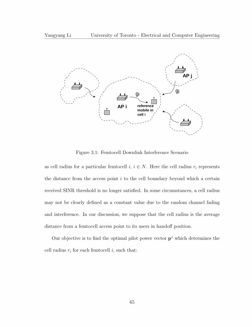
Yangyang Li University of Toronto - Electrical and Computer Engineering
AP i reference mobile in cell i
gigj
AP j
Figure 3.1: Femtocell Downlink Interference Scenario
as cell radius for a particular femtocell i, i ∈ N . Here the cell radius ri represents
the distance from the access point i to the cell boundary beyond which a certain
received SINR threshold is no longer satisfied. In some circumstances, a cell radius
may not be clearly defined as a constant value due to the random channel fading
and interference. In our discussion, we suppose that the cell radius is the average
distance from a femtocell access point to its users in handoff position.
Our objective is to find the optimal pilot power vector p∗ which determines the
cell radius ri for each femtocell i, such that:
65

Yangyang Li University of Toronto - Electrical and Computer Engineering
max t (3.1)
s.t. ri ≥ t, i = 1, 2, ..., N
0 ≤ pi ≤ pmaxi, i = 1, 2, ..., N
where t is a newly introduced scalar variable. The above optimization is equivalent
to a Max-Min problem: max min ri, i = 1, 2, ..., N , which maximizes the minimum
femtocell radius in the network. pmaxi defines the maximum pilot power in each
cell i which constrains the cell radii solved from (3.1). The above objective function
equalizes all femtocells’ coverage by maximizing the smallest cell size in the network.
This objective is important for pilot management in a fairness point of view because
any femtocell is not supposed to suffer much smaller cell coverage than others.
According to (3.1), all user-deployed access points cooperate to smooth out the
potential big variance of cell sizes in an arbitrary infrastructure topology. This
objective is much more flexible than setting a constant cell radius of 10 meters
for all femtocells as studied in previous work [10] and [11]. In addition, both the
femtocell-to-macrocell and femtocell-to-femtocell interference are considered in our
model in the following discussion.
Now we introduce a function Fi(p) to replace the radius expression ri in (3.1)
and the primal problem becomes:
66

Yangyang Li University of Toronto - Electrical and Computer Engineering
max t (3.2)
s.t. Fi(p) ≥ t, i = 1, 2, ..., N
0 ≤ pi ≤ pmaxi, i = 1, 2, ..., N
The function of Fi(p) maps the variable power vector p to each of the cell radius
ri. We can use this replacement because a particular pilot power allocation pattern
p uniquely determines each femtocell size in the network.
In order to define Fi(p) for each cell i = 1, 2, ..., N , we denote the cell radius ri as
the distance between the access point i and a reference mobile located at l = (x, y)T
in cell i. As shown in Figure 3.1, such a reference mobile is illustrated by a terminal
that is normally on the edge of the cell and probably in the handoff process. x
and y are the two-dimensional coordinates that denote the physical location of the
reference mobile terminal in cell i. We show the received SINR on the reference
mobile as:
Ci =pi · gi(ri)∑
j 6=i pj · gj,i(l) + ni
i, j = 1, 2, ..., N (3.3)
In addition to pi denoting the pilot strength of the ith access point, gi(ri) represents
the channel gain from the access point i to the reference mobile and is a function of
the their distance ri. gi(ri) can be obtained by the signal path loss model which is
a unique channel characterization of cell i. pj and gj,i(l) for j ≤ N and j 6= i denote
67

Yangyang Li University of Toronto - Electrical and Computer Engineering
the pilot power and the downlink interference gain from the jth cell to the reference
mobile in cell i. Ci is a weight parameter to balance different femtocell sizes based
on specific traffic distribution in the network. The bigger setting of Ci will make
larger cell size configuration for femtocell i. Finally, ni denotes the received noise
power on the reference mobile terminal.
The measurement of the interference gain gj,i(l) can be easily performed in a
CDMA cellular system. A reference mobile in soft handoff process can simultane-
ously talk to multiple neighbouring access points/base stations, which makes both
information of pj and gj,i(l) easy to know by the network controller.
Then, from equation (3.3) we get the expression of Fi(p) as:
Fi(p) = ri = g−1i (
1
pi
· Ci · [∑j 6=i
pj · gj,i(l) + ni]), i, j = 1, 2, ..., N (3.4)
where the function of g−1i (·) denotes the inverse function of finding the cell radius
from the pilot power based on the path loss function gi(·). Therefore, the original
problem in (3.2) can be written as:
max t (3.5)
s.t. g−1i (
1
pi
· Ci · [∑j 6=i
pj · gj,i(l) + ni]) ≥ t, i, j = 1, 2, ..., N
0 ≤ pi ≤ pmaxi, i = 1, 2, ..., N
The convexity and mathematical tractability of the above problem are deter-
68

Yangyang Li University of Toronto - Electrical and Computer Engineering
mined by specific path loss expression gi(ri) for each cell i. Note that gi(ri) is a
monotonically decreasing function, i.e. bigger cell radius ri always leads to smaller
channel gain of path loss. Therefore, the problem (3.5) can be rewritten as the
following:
max t (3.6)
s.t.1
pi
· Ci · [∑j 6=i
pj · gj,i(l) + ni] ≤ gi(t), i, j = 1, 2, ..., N
0 ≤ pi ≤ pmaxi, i = 1, 2, ..., N
In order to find the solution for problem (3.6), we assume that the path loss
characterization gi(·) in each femtocell i has the same mathematical expression.
Then, the maximization on scalar t can be replaced by the minimization on g(t)
and the problem (3.6) can be written as:
min g(t) (3.7)
s.t.1
pi
· Ci · [∑j 6=i
pj · gj,i(l) + ni] ≤ g(t), i, j = 1, 2, ..., N
0 ≤ pi ≤ pmaxi, i = 1, 2, ..., N
Finally, the problem (3.7) is equivalent to the following expression:
69
Yangyang Li University of Toronto - Electrical and Computer Engineering
min maxCi · [
∑j 6=i pj · gj,i(l) + ni]
pi
, i, j = 1, 2, ..., N (3.8)
s.t. 0 ≤ pi ≤ pmaxi, i = 1, 2, ..., N
which is a convex and linear fractional programming (LFP) problem [53]. There are a
couple of methods to solve an LFP problem by either transforming it to an equivalent
linear programming (LP) problem or solving a sequence of linear programs through
only re-computing the local gradient of the objective function. In our problem (3.8),
we also need to know the factor gj,i(l) which determines the interference power gain
from adjacent cells j to the reference mobile in cell i. In next section, we propose a
discrete-time power updating procedure in order to find the optimal cell coverage r∗
and pilot power configuration p∗. The position of the reference mobile in each cell
is updated in a periodical manner, which facilitates the search for optimal solution.
Our formulation (3.8) incorporates two cellular factors for pilot power optimiza-
tion in a user-deployed cellular network. First, each of the femtocells should be able
to characterize its channel environment through a unique characterization of g(r).
This can be done by different means based on specific cellular standard under con-
sideration. For example, in a Time Division Synchronous Code Division Multiple
Access (TD-SCDMA) network, the uplink communication is synchronized on chip
level which allows the access point to measure the signal path loss in a cell. Second,
by implementing different weight parameters Ci to femtocells, the cell sizes can be
70

Yangyang Li University of Toronto - Electrical and Computer Engineering
adaptively balanced according to specific resource allocation requirement.
3.2 An Autonomous Pilot Management Procedure
Figure 3.2: Autonomous BS Pilot Power Update Procedure
Based on the proposed optimization model, we study a practical procedure for
autonomous pilot management in a 3G cellular network as shown in Figure 3.2. All
femtocells are supposed to register themselves to a network controller ACM managed
71

Yangyang Li University of Toronto - Electrical and Computer Engineering
by the network operator. The software in ACM solves the optimization problem (3.5)
and sends commands for pilot power configuration. The whole control procedure is
considered to follow two stages under different traffic conditions as discussed in the
following.
When traffic load is low in a femtocell, the access point can enter sleep mode
in order to reduce the pilot pollution to its neighbours (Step 1). An access point
in sleep mode is supposed to turn off its downlink radio when no traffic shows up
for a certain period of time. The uplink radio of the access point listens to the
pilot signals from the neighbouring co-channel cells and build up a neighbour list as
the environment characterization (Step 2). Based on the result from environment
listening, a femtocell estimates the signal propagation model g(·) for solving the
optimization problem (3.5).
When traffic goes high in a femtocell, pilot management needs to be optimized
according to (3.5). Femtocells in sleep mode can be woken up by mobile users
who has data to transmit (Step 3). The wake-up signal is received by a number of
access points that forward the signal identification together with the signal strength
received to the network controller. The controller then determines the access point
that received the maximum signal and commands that access point to respond to
the user and initiate a connection with that user. Once a femtocell is chosen to
be woken up (Step 4), its pilot strength must be initiated to a minimum value
72

Yangyang Li University of Toronto - Electrical and Computer Engineering
pmin (Step 5). Then, based on gi(·) and Ci for each cell i = 1, 2, ..., N , the ACM
can iteratively update the pilot power allocation by a discrete power level ∆p in
each cell according to (3.5) (Step 6 and 7). The updating process keeps going
until the network converges at the time when all the cell sizes reach their optimal
configuration, i.e. r = r∗ (Step 8). The whole procedure is supposed to take a while
to finish depending on the network scale and the computational capability of ACM.
3.3 Performance Results
We simulate the performance of our algorithm, i.e. a femtocell access point auto-
matically updates its pilot power until either the optimal cell radius r∗ is satisfied
or the maximum pilot power pmax is reached. In a WCDMA cellular system, pmax is
normally set to 10% of the total transmit power of a base station. In our simulation,
we set the maximum transmit power of a femtocell access point 150mW which gives
pmax = 15mW.
The pilot power update has been simulated as a discrete time process. We set
the identical initial power pmin=1mW for all femtocells and a step unit ∆p=0.5mW
is updated during each runtime of the procedure represented in Figure 3.2. For sim-
plicity, Ci is set to 1 for all femtocells which means no biased cell size configuration is
considered in the network. In practice, this parameter can be adaptively configured
reflecting the relative traffic density across cells. Also, the same path loss model
73
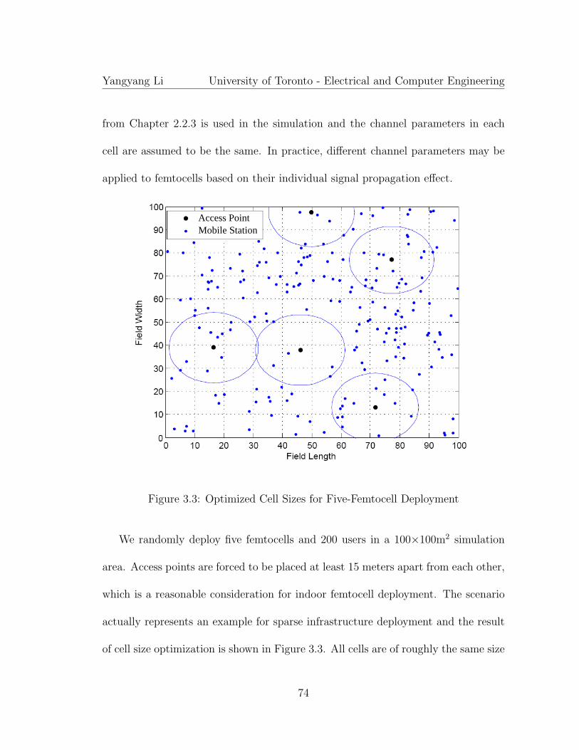
Yangyang Li University of Toronto - Electrical and Computer Engineering
from Chapter 2.2.3 is used in the simulation and the channel parameters in each
cell are assumed to be the same. In practice, different channel parameters may be
applied to femtocells based on their individual signal propagation effect.
Access PointMobile Station
Figure 3.3: Optimized Cell Sizes for Five-Femtocell Deployment
We randomly deploy five femtocells and 200 users in a 100×100m2 simulation
area. Access points are forced to be placed at least 15 meters apart from each other,
which is a reasonable consideration for indoor femtocell deployment. The scenario
actually represents an example for sparse infrastructure deployment and the result
of cell size optimization is shown in Figure 3.3. All cells are of roughly the same size
74

Yangyang Li University of Toronto - Electrical and Computer Engineering
with the implementation of maximum pilot power pmax = 15mW. This is because
cells are well spread out in space with little interference between each other. Each
access point allocates the highest pilot power to maximize the individual cell radius
according to (3.5), and associate the largest number of users in vicinity. Users that
are not covered by any of the femtocells are still served by the macrocell base station
(not shown in the Figure) as public users.
Access PointMobile Station
Figure 3.4: Optimized Cell Sizes for Ten-Femtocell Deployment
Now we double the femtocell deployment density to ten in the same 100×100m2
area and maintain the number of mobiles unchanged as 200. After autonomous
75

Yangyang Li University of Toronto - Electrical and Computer Engineering
adaptation to the new infrastructure topology according to (3.5), cell size config-
uration shows different result as shown in Figure 3.4. Access points that happen
to be closely deployed in the central-right and left areas automatically reduce the
pilot power and shrink their cell size. Cells that are more spread out in other areas
still allocate full pilot power due to lower interference among them. Compared to
the simulation results in [10] with constant cell size configuration, our algorithm
adaptively determines the pilot power allocation according to the dynamic change
of infrastructure topology. Without regular cell planning in the simulation area,
the algorithm works to well balance the size of different cells with minimum size
variance. This is because the objective in (3.5) already maximizes the smallest cell
size in the network.
Now we vary the number of femtocells deployed in the simulation area from 0 to
20 and study the variance of the cell coverage in the network. The result is shown
in Figure 3.5 which compares two pilot power configuration schemes. One is to have
a constant pilot power of 15mW in each femtocell and the other is based on our
autonomous pilot update algorithm. We find that smaller cell variance is achieved
in the network with our scheme. When the number of femtocells increases to 20 in
100×100m2 area, autonomous cell configuration keeps the cell variance below 8m
while the traditional method causes a bigger value up to 14m. Low cell size variance
is automatically achieved by the Max-Min operation in (3.5), which offers equalized
76

Yangyang Li University of Toronto - Electrical and Computer Engineering
0 2 4 6 8 10 12 14 16 18 200
2
4
6
8
10
12
14
16
18
20
Number of Femtocells in Simulation Area
Var
ianc
e of
Fem
toce
ll C
over
age
in D
iam
eter
(m
)
Constant Pilot Power Configuration, pi = 15mW
Autonomous Pilot Power Configuration, pmax = 15mW
Figure 3.5: Variance of Femtocell Coverage in Diameter
service coverage for different femtocell users in the network.
3.4 Summary
In this chapter, we studied a method to configure the femtocell pilot power in an au-
tonomous cellular network. The method can be applied to various cellular standards
when channel propagation model is easy to measure from the network environment.
Performance results showed the effect of auto-configuration of the cell sizes based
on the knowledge of signal propagation model and network traffic distribution.
77

Chapter 4
A MAC Protocol Design for
Autonomous Cellular Resource
Allocation
In Chapters 2 and 3, we have studied two critical issues in a user-deployed cellu-
lar network, i.e. cognitive interference management and autonomous pilot power
management. Now, our work leaves the third problem interesting to study, which
is about cellular resource assignment across different cells. In traditional cellular
networks with regular cell planning, cellular resource is basically allocated to differ-
ent cells in a uniform manner. In autonomous cellular networks, spectrum resource
is spatially reused in a random way and traffic requirement in each cell is of big
78

Yangyang Li University of Toronto - Electrical and Computer Engineering
difference from others. In this chapter, we design a Media Access Control (MAC)
protocol which schedules packet transmission in each cell and balances resource al-
location between neighbouring cells. Compared to the existing work [54] and [55]
our scheduler works in a much simpler manner requiring less exchange of the chan-
nel information between neighboring cells. Performance results are evaluated by
simulation in a cellular WiFi system with autonomous infrastructure deployment.
In our discussion, we focus on downlink communication in a cellular network
and interference management is realized by power control between co-channel cells.
In Section 4.1, we first study a generic downlink power allocation model in an
autonomous cellular network. Based on each user’s QoS requirement, the downlink
transmit power in each cell is optimized for interference minimization. In Section 4.2
and 4.3, we present a practical MAC protocol design which facilitates the realization
of cooperative power allocation in different cells.
4.1 Generic Model for Downlink Power Manage-
ment
We assume that K co-channel cells are randomly deployed in a geographical area as
shown in Figure 3.1. Omni-directional antennas are implemented on both the base
station and mobiles such that power radiation in downlink is isotropic in each cell.
79

Yangyang Li University of Toronto - Electrical and Computer Engineering
For each base station k serving the ith user ik, its downlink transmit power pk,ik
needs to produce a receive power margin over the total co-channel interference. We
denote γk,ik as the expected SINR threshold for the ith user in the kth cell, which
reflects the QoS requirement determined by higher layer applications. Our purpose
is to find the minimum transmit power allocation in each cell which satisfies each
user’s QoS requirement. This leads to the very generic formulation of the following
optimization problem:
min α (4.1)
s.t. pk,ik ≤ α · Pmax, k = 1, 2, ..., K (4.2)
pk,ik · gk,ik∑j 6=k pj,ij · gj,ik + nk,ik
≥ γk,ik , j, k = 1, 2, ..., K (4.3)
pk,ik ≥ 0, k = 1, 2, ..., K (4.4)
α ≥ 0, (4.5)
where the constraints in (4.2) limit the transmit power of each base station by a
multiplying factor of α. The minimization of α automatically minimizes the power
allocation for each base station. Here we have supposed that Pmax is same for all
base stations deployed by users. The group of constraints in (4.3) guarantees the
QoS requirement for each user ik in the kth cell. gk,ik denotes the channel gain
from the kth base station to its own mobile user ik. For j 6= k, pj,ij denotes the
transmit power of the neighbouring jth base station to its own ijth user, and gj,ik
80

Yangyang Li University of Toronto - Electrical and Computer Engineering
is the downlink interference gain from the jth base station to the user ik in the
interested cell k. Therefore, the whole term of pj,ij · gj,ik represents the received
downlink interference power from the jth base station to the current user ik in cell
k. The optimization variables are scalar α and the K × 1 power allocation vector
p; pk,ik , gk,ik , gj,ik and Pmax are constants. Here we have assumed that the SINR
constraints in (4.3) are such that the problem exists at least one feasible solution.
Formulation (4.1) gives the most generic description of the problem, i.e. when
a certain transmission scheduling to users (i1, i2, ..., iK) is determined in all K cells
at a particular time, the optimal power allocation is to minimize the margin of
pk,ik/Pmax over all base stations. The minimal vector p* produces the lowest power
radiation of each base station in order to meet the QoS requirement for the current
user being served in each cell.
The above problem is not easy to solve in practice because of its mathematical
tractability and the unknown parameters of gj,ik for j 6= k, i.e. the instantaneous
interference gain from each neighbouring base station to the scheduled user of in-
terest. Because the total downlink interference always comes at the same time from
each neighbouring base station, it is not realistic to know the interference level of
each interfering neighbouring base station in order to solve the problem. Previous
research work [54] has proposed a scheduling scheme that maximized the cellular
spectrum efficiency provided each interference metric is known in a fixed cellular
81

Yangyang Li University of Toronto - Electrical and Computer Engineering
network without user mobility.
4.2 A MAC Protocol Design for Cellular Power
Allocation
P
Figure 4.1: Three Basic Time Notions
Since the instantaneous co-channel interference metric is hard to obtain by users,
we want to do some regular channelization that facilitates power allocation to base
stations. We first break the total base station transmit power into N different levels
p = (p1, p2, ..., pN), p1 ≤ p2 ≤ ... ≤ pN , with some constant power gap, e.g. 2dB.
Then we want to come up with a protocol that manages the the allocation of the
power vector p in each cell. We define a notion of service period (SP) in time
domain as shown in Figure 4.1, which represents the period of updating the power
allocation to base stations. A pilot or beacon frame defines the start of an SP similar
to the concept of service interval (SI) in the IEEE 802.11e standard [56]. An SP
82

Yangyang Li University of Toronto - Electrical and Computer Engineering
can be further partitioned into into N power bins (PB) with equal length over time.
At the start of each PB , a short pilot frame is broadcast to users announcing the
transmit power used in the following PB time, which takes one of the N values from
the power allocation vector p. A network controller takes charge of power vector
assignment to different base stations in a synchronized manner in time domain,
which allows each base station to give a regular announcement of an interference
map to its neighbours. The minimum length of PB configuration depends on the
speed of channel variation in the network. Mobile users that are served inside a PB
duration are supposed to see a constant channel envelope, which leads to a couple
of milliseconds in a fast fading channel environment.
(P1, P2, P3, P4)
(P4, P3, P2, P1)
Figure 4.2: Power Vector Allocation
Figure 4.2 illustrates an example protocol for power vector allocation. Suppose
that five co-channel cells are deployed by users in a certain geographical area where
83

Yangyang Li University of Toronto - Electrical and Computer Engineering
the two shaded cells represent the areas with relatively high traffic requirement. A
good power allocation scheme intuitively leads to the results shown in Figure 4.2
where the shaded cells can obtain the vectors with reversed power allocation pattern.
Other cells exemplified for less traffic requirement have no need for full power vector
allocation. The time layout of SP and PB has to be perfectly lined up with good
synchronization as shown in Figure 4.3. This can be done by a network controller
(e.g., RNC or ACM) that coordinates the transmission activity in different cells
and manages the power vector allocation for each base station. By coordinating the
power allocation pattern on different base stations, their cell sizes keep compensating
from each other to mitigate the mutual interference in the network.
(12ms for example)
Figure 4.3: Synchronized Power Allocation Vector
Based on this approach, the downlink power control problem in (4.1) can be
replaced by two procedures of power vector allocation to each base station and user
84

Yangyang Li University of Toronto - Electrical and Computer Engineering
scheduling based on a particular power allocation pattern in each cell. Such a chan-
nelization protocol regularizes the interference pattern in the network which makes
intercell scheduling easier to implement in comparison to the generic problem (4.1).
A base station needs to schedule users to the right PB with a constant interference
level received from its neighbouring cells. This facilitates the interference manage-
ment based on the easy management of power vector allocation to different base
stations.
Now we want to study the method to determine the power allocation vector for
each base station. The synchronized power allocation pattern from Figure 4.3 can
be represented by a K ×N matrix as follows:
P =
p11 p12 ... p1N
p21 p22 ... p2N
: : : :
pK1 pK2 ... pKN
, (4.6)
where each row vector represents the power allocation in each PB during an SP and
each column vector denotes the power allocation to different base stations within a
certain PB duration. K is the total number of cells in the whole service area and
N is the number of PB in one SP . In practice, the bigger value of N leads to a finer
channelization pattern. The optimized power allocation for each base station k is
to find the correct permutation of elements in each row vector pk such that:
85

Yangyang Li University of Toronto - Electrical and Computer Engineering
min maxK∑
k=1
pk,n, n = 1, 2, ..., N (4.7)
The above Min-Max problem minimizes the sum transmit power of all base sta-
tions during each PB duration. The optimal solution P ∗ characterizes the complete
power allocation pattern for all base stations during an SP . The length of one SP
should be around the same magnitude of the average channel coherence time such
that the channel condition in terms of (downlink channel gain) / (total interference
power) can remain roughly constant during an SP . In Figure 4.3, one SP is exem-
plified by 12 ms which can be translated to a terminal moving speed of 42km/h on
the 900MHz carrier frequency in a Rayleigh fading environment.
Now that the transmit power from each base station is regularized over time, a
user can easily measure a channel SINR vector γ = (γ1, γ2, ...γN) in an SP based
on the received PB pilot signal. Knowing the channel condition in each PB a user
can send back γ in uplink in order to facilitate the base station to schedule users in
the next SP time period.
4.3 Scheduler Design for Base Stations
In this section we study a scheduler that allocates mobile users to the right PB in a
cell based on their channel measurement γ and data traffic requirement. So far two
86

Yangyang Li University of Toronto - Electrical and Computer Engineering
vectors p∗ and γ have been determined at each base station. The vector p∗ specifies
the transmission power pattern in one SP , during which the channel conditional
is characterized by the SINR vector γ. We equally divide the length of each PB
into L different service slots (SS ) as shown in Figure 4.1. Each SS represents the
unit resource time TSS assigned to users. We denote the element ci,j of the variable
M ×N matrix C as the number of SS allocated to the ith mobile in the jth PB :
C =
c11 c12 ... c1N
c21 c22 ... c2N
: : : :
cM1 cM2 ... cMN
, (4.8)
where M is the number of users in the cell of interest and N is the number of PBs
inside one SP . The matrix C fully specifies the transmission slot allocation for each
mobile in each PB . Each row vector (cm1 ... cmN) denotes the SS allocation for
user m in each PBs; And the elements summation of the column vector (c1j...cMj)T
represents the total number of the SS inside a specific PB time n, such that:
M∑m=1
cm,n ≤ L, n = 1, 2, ..., N (4.9)
The optimal scheduler C∗ is such that:
87

Yangyang Li University of Toronto - Electrical and Computer Engineering
minM∑
m=1
N∑n=1
cm,n (4.10)
s.t.
N∑n=1
cm,n · R(γm,n) · TSS ≥ Bi, m = 1, 2, ...,M (4.11)
M∑m=1
cm,n ≤ L, n = 1, 2, ..., N (4.12)
cm,n ≥ 0, m = 1, 2, ...,M and n = 1, 2, ..., N (4.13)
where the constraints in (4.11) guarantees a complete finish of the user m’s traffic
Bm in the following SP , which is determined by the service requirement of the user.
The function R(·) transforms the achievable data rate from the channel SINR γm,n
based on some acceptable bit error rate (BER). Constraints in (4.12) bounded the
total available number of SS in one PB and (4.13) guarantees the non-negative
number of SS allocation.
The optimization objective (4.10) minimizes the total downlink transmission
time given a certain amount of traffic requirement in each cell. This implicates that
mobiles with better SINR condition will be allocated to stronger PB ’s. Along with
the optimization requirement from (4.7) which allocates complementary transmit
power between cells, the above scheduler automatically creates orthogonal trans-
missions when the aggregate cell traffic is low. When the traffic load goes up in the
network, the intercell channelization turns from orthogonal to sub-orthogonal based
on the QoS constraints defined in (4.11). Cells with low traffic automatically release
88

Yangyang Li University of Toronto - Electrical and Computer Engineering
their power resource to other high traffic cells. The algorithm generalizes the work
in paper [55] which simply performs orthogonal channelization between co-channel
cells with low spectrum efficiency.
The optimization problem (4.10) can be transformed into a standard linear pro-
gramming format in the following discussion. We align the row vectors in matrix
C = {cT1 ,cT
2 ,· · · ,cTM} and make it to a single vector c:
c =
c1
...
cM
= [c11 . . . c1N . . . cM1 . . . cMN ]T (4.14)
To get the same expression in (4.11), we define an M × (M ·N) matrix A1:
A1 = Tss ·
R11 . . . R1N 0 . . . 0 0 . . . 0
0 . . . 0 R21 . . . R2N 0 . . . 0
.... . .
0 . . . 0 0 . . . 0 RM1 . . . RMN
(4.15)
and a M × 1 vector b1 = [B1 . . . BM ]T . Then, the first constraint (4.11) can be
expressed in a vector production form:
A1c � b1 (4.16)
89

Yangyang Li University of Toronto - Electrical and Computer Engineering
Similarly, we can define an M × (M ·N) matrix A2:
A2 =
1 0 . . . 0 1 0 . . . 0 1 0 . . . 0
0 1 0 . . . 0 1 0 . . . 0 1 0 . . .
.... . .
0 . . . 0 1 0 . . . 0 1 0 . . . 0 1
(4.17)
and an M×1 vector b2 = L ·1. Then, the second constraint (4.12) can be expressed
as:
A2c � b2 (4.18)
Therefore, the original optimization problem (4.10) can be written in the follow-
ing standard linear programming form, which can be easily solved either analytically
or by software programs.
min 1Tc (4.19)
s.t. A1c � b1 (4.20)
A2c ≺ b2 (4.21)
c � 0 (4.22)
90

Yangyang Li University of Toronto - Electrical and Computer Engineering
Parameter Value
Length of SP 10ms
Number of PB in one SP 4
Number of SS in one PB 5
AP Transmission Rate 54Mbps
AP Transmit Power 20dBm, 17dBm, 15dBm, 13dBm
Number of APs 5
AP Deployment Random
Simulation Area 2500m2
Packet Arrival Model Poisson
Data Packet Payload 500Bytes
ACK Packet Payload 14Bytes
RTS/CTS Yes
Table 4.1: Simulation Parameters
4.4 Performance Results
The downlink performance is studied by simulation in a multi-cell WiFi (IEEE
802.11a) system. Five co-channel access points are randomly placed in a 50×50m2
area as shown in Figure 4.2 and simulation parameters are displayed in Table 4.1.
Fifteen mobiles are uniformly deployed in each cell to share the maximum 54Mbps
radio transmission rate. Each access point has four synchronized PB channel al-
location with the transmit power levels: 20dBm, 17dBm, 15dBm, and 13dBm. In
practice, the transmit power in each PB can be adaptively changed by the network
controller according to the specific traffic load distribution in the network. In our
91

Yangyang Li University of Toronto - Electrical and Computer Engineering
simulation, we make them fixed values for simplicity. The allocation of PB for each
access point follows the method in (4.7). And each access point schedules the mobile
uses based on the optimization algorithm in (4.10). The signal path loss model used
in simulation is characterized by the following equation:
L(d) = L + γlog10(d),
where L = 30dB, γ = 3.5 and the Lognormal fading deviation is set to 8dB.
1. Power Vector Initialization, pmin = (p1, …, p1)
2. User QoS Satisfaction?
5. Mobile User Scheduling, algorithm (4.10)
3. Power Vector Update, min(p) + 2dB
4. Power Matrix Update, algorithm (4.7)
Yes
No
6. User QoS Satisfaction?No
Figure 4.4: Autonomous Cellular Resource Allocation Procedure
92

Yangyang Li University of Toronto - Electrical and Computer Engineering
Now we discuss a procedure used in our simulation in Figure 4.4 which realizes
autonomous power allocation and resource scheduling in each cell. At the initial
stage when cell traffic is low, all access points set their transmit power to the lowest
level p1 which generates minimum interference to neighbouring cells (Step 1). When
cell traffic increases, each access point periodically checks the QoS satisfaction from
each user based on the optimization constraint (4.11) (Step 2). If there is a need
to increase the resource allocation to handle more cell traffic, the access point au-
tonomously updates its transmit power vector by adding 2dB into its lowest PB
(Step 3). Then, the global power allocation matrix needs to be updated following
the algorithm (4.7) (Step 4). After the power vector gets updated in each cell, re-
source scheduling is implemented by solving the optimization problem (4.10) (Step
5). Each access point is supposed to autonomously update the transmit power and
cellular resource allocation in a periodic manner (Step 6).
With the above settings, we compare the performance of our protocol and the
ordinary IEEE 802.11 standard based on CSMA/CA. We show the performance of
the center cell shown in Figure 4.2. First, we study a case that the aggregate traffic
load in four neighbouring cells is set to 20Mbps, which is supposed to coin a low
network interference scenario. From the blue curves in Figure 4.5, we see that the
increase of the downlink transmission frame error rate (FER) is much slower with
our scheduling approach. This is because of the fact that the optimized channel
93

Yangyang Li University of Toronto - Electrical and Computer Engineering
allocation determined by (4.7) and (4.10) creates orthogonal intercell channels over
time. When we change the interference environment to a worse case with doubled
traffic load to 40Mbps in neighbouring cells, the benefit gap becomes even larger.
This is because the interference has been well managed by creating sub-orthogonal
intercell channelization across the five cells. The cell sizes well compensate with
each other that reduces the co-channel interference.
0 2 4 6 8 10 12 14 16 1810
−3
10−2
10−1
Cell Traffic Load (Mbps)
Fra
me
Err
or R
ate
with control, 20Mbps surrounding trafficwithout control, 20Mbps surrounding trafficwith control, 40Mbps surrounding trafficwithout control, 40Mbps surrounding traffic
Figure 4.5: Average Downlink Frame Error Rate
The performance of average packet transmission delay is shown in Figure 4.6.
Again, blue curves show that the average downlink transmission delay gets worse for
both cases as the traffic load increases in low interference environment. However,
94

Yangyang Li University of Toronto - Electrical and Computer Engineering
an average of 20% throughput gain is achieved by our protocol within the bounded
delay of 50ms. This is because the packet retransmissions caused by the MAC layer
packet collision have been effectively reduced.
0 5 10 15 20 250
5
10
15
20
25
30
35
40
45
50
Cell Traffic Load (Mbps)
Mea
n P
acke
t Del
ay (
ms)
with control, 20Mbps surrounding trafficwithout control, 20Mbps surrounding trafficwith control, 40Mbps surrounding trafficwithout control, 40Mbps surrounding traffic
Figure 4.6: Average Downlink Transmission Delay
With a doubled traffic load in the neighbouring co-channel cells, a worse delay
performance is represented by the red curves in Figure 4.6. One can see that with
our control approach, the delay performance is less sensitive to the traffic increase
in cells. And a bigger throughput benefit can be achieved within the same bounded
delay value compared to the previous case. This converges to the FER results that
our channelization and scheduling protocol better improves the network performance
95

Yangyang Li University of Toronto - Electrical and Computer Engineering
in high network interference scenarios.
4.5 Summary
In this chapter we proposed an intercell channelization scheme that manages net-
work interference and balances radio resource allocation across cells. The scheme
can be implemented as an add-on control function to some of the existing cellular
standards. A network controller creates orthogonal/sub-orthogonal channels with
adaptive power allocation in different cells. Unlike the CDMA 1x EV-DO technol-
ogy, the scheme is supposed to be more applicable in static or slow fading channel
environment, e.g., femtocell application scenarios. When the global traffic distribu-
tion parameter is known in a cellular network, the transmit power of each cell should
be adaptively adjusted to meet the resource balance requirement. The scheme may
also be used in cellular MIMO systems where the spatial channel multipaths are
rich and the power control can be applied as an effective method for interference
management.
96

Chapter 5
Conclusion
In this work, a 4G method of deploying a cellular network is introduced based
on the concept of autonomous network management. Interference management,
cell size configuration, mobile handoff management and network resource allocation
must be carried out in an autonomous manner based on the knowledge of network
environment. A cellular framework that covers the above issues is developed based
on the method of network listening and cognitive radio configuration. Future cellular
networks are supposed to be more software dependent. Optimization algorithms can
be easily applied to hardware equipment, which offers strong radio configurability
for cellular spectrum management.
Future work will be focusing on the uplink study based on the idea of cognitive
channel allocation. Network capacity will be studied based on different strategies for
97

Yangyang Li University of Toronto - Electrical and Computer Engineering
user access, i.e. open, closed and hybrid. Other network factors will be considered
in the model for pilot power management, such as the traffic distribution in cells
and mobile handoff requirement between macrocell and femtocells.
98

Bibliography
[1] V. H. Mac Donald. The cellular concept. In The Bell System Technical Journal,
volume 58, January 1979.
[2] B. G. Evans and K. Baughan. Visions of 4G. In Electronics and Communication
Engineering Journal, pages 293–303, December 2000.
[3] E. S. Sousa. Autonomous infrastructure wireless networks. In 16th IST Mobile
and Wireless Communications Summit, July 2007.
[4] E. S. Sousa. Autonomous infrastructure wireless networks. US patent, Publi-
cation Number: WO/2005/120101, December 2005.
[5] Motorola. Long term evolution (LTE): A technical overview. Technical White
paper 2007.
[6] E. Dahlman, H. Ekstrom, A. Furuskar, Y. Jading, J. Karlsson, M. Lundevall,
and S. Parkvall. The 3G long-term evolution - radio interface concepts and
99

Yangyang Li University of Toronto - Electrical and Computer Engineering
performance evaluation. In IEEE 63rd Vehicular Technology Conference (VTC
Spring ’06), pages 137–141, May 2006.
[7] H. Lei, L. Zhang, X. Zhang, and D. Yang. System level evaluation of 3G long
term evolution. In IEEE 18th International Symposium on Personal, Indoor
and Mobile Radio Communications (PIMRC ’07), September 2007.
[8] V. Chandrasekhar, J. Andrews, and A. Gatherer. Femtocell networks: a survey.
IEEE Communication Magazine, 46(9), September 2008.
[9] The OpenBTS Project. http://openbts.sourceforge.net.
[10] H. Claussen. Performance of macro- and co-channel femtocells in a hierarchical
cell structure. In IEEE 18th International Symposium on Personal, Indoor and
Mobile Radio Communications, 2007.
[11] L. T. W. Ho and H. Claussen. Effects of user-deployed, co-channel femtocells on
the call drop probability in a residential scenario. In IEEE 18th International
Symposium on Personal, Indoor and Mobile Radio Communications, 2007.
[12] L. Ho, I. Ashraf, and H. Claussen. Evolving femtocell coverage optimization
algorithms using genetic programming. In IEEE 20th International Symposium
on Personal, Indoor and Mobile Radio Communications, September 2009.
100

Yangyang Li University of Toronto - Electrical and Computer Engineering
[13] Lester T.W. Ho, Imran Ashraf, and Holger Claussen. Evolving femtocell cover-
age optimization algorithms using genetic programming. In IEEE 19th Inter-
national Symposium on Personal, Indoor and Mobile Radio Communications
(PIMRC ’09), September 2008.
[14] David Lopez-Perez, Akos Ladanyi, Alpar Juttner, and Jie Zhang. OFDMA
femtocells: A self-organizing approach for frequency assignment. In IEEE 19th
International Symposium on Personal, Indoor and Mobile Radio Communica-
tions (PIMRC ’09), September 2008.
[15] I. Guvenc, M. R. Jeong, F. Watanabe, and H. Inamura. A hybrid frequency
assignment for femtocells and coverage area analysis for co-channel operation.
In IEEE Communications Letters, volume 12, pages 880–882, December 2008.
[16] V. Chandrasekhar and J. G. Andrews. Spectrum allocation in two-tier net-
works. In 42nd Asilomar Conference on Signals, Systems, and Computers,
pages 1583–1587, October 2008.
[17] T. H. Kim and T. J. Lee. Throughput enhancement of macro and femto net-
works by frequency reuse and pilot sensing. In IEEE International Performance,
Computing, and Communications Conference (IPCCC ’08), pages 390–394, De-
cember 2008.
101
Yangyang Li University of Toronto - Electrical and Computer Engineering
[18] Yi Wu, Dongmei Zhang, Hai Jiang, and Ye Wu. A novel spectrum arrange-
ment scheme for femto cell deployment in LTE macro cells. In IEEE 19th
International Symposium on Personal, Indoor and Mobile Radio Communica-
tions (PIMRC ’09), September 2008.
[19] M. Husso, J. Hamalainen, R. Jantti, and A. M. Wyglinski. Adaptive anten-
nas and dynamic spectrum management for femtocellular networks: A case
study. In 3rd IEEE Symposium on New Frontiers in Dynamic Spectrum Access
Networks (DySPAN ’08), October 2008.
[20] Yong Bai, Juejia Zhou, Liu Liu, Lan Chen, and Hiroyuki Otsuka. Resource
coordination and interference mitigation between macrocell and femtocell. In
IEEE 19th International Symposium on Personal, Indoor and Mobile Radio
Communications (PIMRC ’09), September 2008.
[21] Joseph O’Carroll, Holger Claussen, and Linda Doyle. Partial GSM spectrum
reuse for femtocells. In IEEE 19th International Symposium on Personal, In-
door and Mobile Radio Communications (PIMRC ’09), September 2008.
[22] Juan Espino and Jan Markendahl. Analysis of macro - femtocell interference
and implications for spectrum allocation. In IEEE 19th International Sympo-
sium on Personal, Indoor and Mobile Radio Communications (PIMRC ’09),
September 2008.
102

Yangyang Li University of Toronto - Electrical and Computer Engineering
[23] D. Das and V. Ramaswamy. On the reverse link capacity of a CDMA network
of femto-cells. In IEEE Sarnoff Symposium, April 2008.
[24] T. Nihtila. Capacity improvement by employing femto cells in a macro cell
HSDPA network. In IEEE Symposium on Computers and Communications
(ISCC ’08), pages 838–843, July 2008.
[25] JuYeop Kim and Dong-Ho Cho. A joint power and subchannel allocation
scheme maximizing system capacity in dense femtocell downlink systems. In
IEEE 19th International Symposium on Personal, Indoor and Mobile Radio
Communications (PIMRC ’09), September 2008.
[26] T. Nihtila. Increasing femto cell throughput with HSDPA using higher order
modulation. In IEEE International Networking and Communications Confer-
ence (INCC ’08), pages 49–53, May 2008.
[27] Eun Jin Hong, Se Young Yun, and Dong-Ho Cho. Decentralized power control
scheme in femtocell networks : A game theoretic approach. In IEEE 19th Inter-
national Symposium on Personal, Indoor and Mobile Radio Communications
(PIMRC ’09), September 2008.
[28] Radio and Physical Layer Working Group. Interference manage-
ment in UMTS femtocells, Femtoforum Whitepaper, December 2008.
http://www.femtoforum.org.
103

Yangyang Li University of Toronto - Electrical and Computer Engineering
[29] H. Claussen, L. T. W. Ho, and L. G. Samuel. Self-optimization of coverage
for femtocell deployments. In Wireless Telecommunications symposium (WTC
’08), pages 278–285, April 2008.
[30] H. Claussen, L. T. W. Ho, and F. Pivit. Effects of joint macrocell and res-
idential picocell deployment on the network energy efficiency. In IEEE 19th
International Symposium on Personal, Indoor and Mobile Radio Communica-
tions (PIMRC ’08), September 2008.
[31] X. Li, L. Qian, and D. Kataria. Downlink power control in co-channel macrocell
femtocell overlay. In 43rd Annual Conference on Information Sciences and
Systems (CISS ’09), pages 383–388, March 2009.
[32] N. Arulselvan, V. Ramachandran, S. Kalyanasundaram, and G. Han. Dis-
tributed power control mechanisms for HSDPA femtocells. In IEEE 69th Ve-
hicular Technology Conference (VTC Spring ’09), April 2009.
[33] H. S. Jo, J. G. Yook, C. Mun, and J. Moon. A self-organized uplink power
control for cross-tier interference management in femtocell networks. In IEEE
Military Communications Conference (MILCOM ’08), November 2008.
[34] M. Z. Chowdhury, R. Won, R. Eunjun, , and M. J. Yeong. Handover be-
tween macrocell and femtocell for UMTS based networks. 11th International
104

Yangyang Li University of Toronto - Electrical and Computer Engineering
Conference on Advanced Communication Technology (ICACT ’09), 1:237–241,
February 2009.
[35] D. Choi, P. Monajemi, S. Kang, and J. Villasenor. Dealing with loud neigh-
bors: the benefit and tradeoffs of adaptive femtocell access. In IEEE Global
Telecommunications Conference (GLOBECOM ’08), November 2008.
[36] S. B. Kang, Y. M. Seo, Y. K. Lee, M. Z. Chowdhury, W. S. Ko, M. N. Irlam,
S. W. Choi, and Y. M. Jang. Soft QoS-based CAC scheme for WCDMA femto-
cell networks. In 10th International Conference on Advanced Communication
Technology (ICACT ’08), volume 1, pages 409–412, February 2008.
[37] Holger Claussen and Doru Calin. Macrocell offloading benefits in joint macro
and femtocell deployments. In IEEE 19th International Symposium on Per-
sonal, Indoor and Mobile Radio Communications (PIMRC ’09), September
2008.
[38] Ping Xia, Vikram Chandrasekhar, and Jeffrey G. Andrews. Open vs closed
access femtocells in the uplink. In IEEE Trans. on Wireless Communications,
submitted on February 2010.
[39] Jacek Gora and Troels E. Kolding. Deployment aspects of 3G femtocells. In
IEEE 19th International Symposium on Personal, Indoor and Mobile Radio
Communications (PIMRC ’09), September 2008.
105

Yangyang Li University of Toronto - Electrical and Computer Engineering
[40] Alvaro Valcarce, David Lopez-Perez, Guillaume De La Roche, and Jie Zhang.
Limited access to OFDMA femtocells. In IEEE 19th International Symposium
on Personal, Indoor and Mobile Radio Communications (PIMRC ’09), Septem-
ber 2008.
[41] D. Davis and Motorola. Femtocells in the home, Briefing Paper, December 2007.
http://www.motorola.com/staticfiles/business/solutions/technologies/femtocells/
documents/static files/femtocells briefing paper.pdf.
[42] picoChip. The case for home base stations, Technical White Paper, Vol
1.1, April 2007. http://www.femtoforum.org/femto/files/file/picochip femto-
cell white paper 1.1.pdf.
[43] S. P. Yeh, S. Talwar, S. C. Lee, and H. Kim. WiMAX femtocells: A perspective
on network architecture, capacity, and coverage. In IEEE Communications
Magazine, pages 58–65, October 2008.
[44] D. Lopez-Perez, A. Valcarce, G. De La Roche, E. Liu, and J. Zhang. Access
methods to WiMAX femtocells: A downlink system-level case study. In 11th
IEEE Singapore International Conference on Communication Systems (ICCS
’08), pages 1657–1662, November 2008.
[45] D. Lopez-Perez, G. De La Roche, A. Valcarce, A. Juttner, and J. Zhang. In-
terference avoidance and dynamic frequency planning for WiMAX femtocells
106

Yangyang Li University of Toronto - Electrical and Computer Engineering
networks. In 11th IEEE Singapore International Conference on Communication
Systems (ICCS ’08), pages 1579–1584, November 2008.
[46] D. Y. Kwak, J. S. Lee, Y. C. Oh, and S. C. Lee. Development of wibro (mobile
WiMAX) femtocell and related technical issues. In IEEE Global Telecommuni-
cations Conference (GLOBECOM ’08), November 2008.
[47] C. Cordeiro, K. Challapali, D. Birru, and N. Sai Shankar. IEEE 802.22: The
first worldwide wireless standard based on cognitive radios. In 1st IEEE Sympo-
sium on New Frontiers in Dynamic Spectrum Access networks (DySPAN ’05),
pages 328–337, November 2005.
[48] F. K. Jondral. Cognitive radio: A communications engineering view. In IEEE
Wireless Communications, pages 28–33, August 2007.
[49] A. Ghasemi and E. S. Sousa. Spectrum sensing in cognitive radio networks: re-
quirements, challenges and design tradeoffs. IEEE Communications Magazine,
46(4), April 2008.
[50] C. E. Shannon. A mathematical theory of communication. Bell System Tech-
nical Journal, 27:379–423, 623–656, July, October 1948.
[51] V. S. Annapureddy and V. V. Veeravalli. Sum capacity of the Gaussian interfer-
ence channel in the low interference regime. In Proceedings of ITA Workshop,
San Diego, CA, January 2008.
107

Yangyang Li University of Toronto - Electrical and Computer Engineering
[52] A. Goldsmith. Wireless Communications. Cambridge University Press, 2006.
[53] S. P. Boyd and L. Vandenberghe. Convex Optimization. Cambridge University
Press, 2004.
[54] M. Rahman, H. Yanikomeroglu, M. H. Ahmed, and S. Mahmoud. Opportunistic
non-orthogonal packet scheduling in fixed broadband wireless access networks.
In EURASIP Journal on Wireless Communications and Networking, the Special
Issue on RRM in 3G+ Systems, 2006.
[55] M. H. Ahmed, H. Yanikomeroglu, and S. Mahmoud. Interference management
using basestation coordination in broadband wireless access networks. Wireless
Communications and Mobile Computing (WCMC), 6:95–103, February 2006.
[56] IEEE Standards Department. Wireless medium access control (MAC) and
physical layer (PHY) specifications: Medium access control (MAC) quality of
service (QoS) enhancements. In IEEE Press, 2005.
[57] Y. Li and E. S. Sousa. Cognitive channel reuse for user-deployed femtocells. In
The 12th International Symposium on Wireless Personal Multimedia Commu-
nications, September 2009.
[58] Y. Li and E. S. Sousa. Base station pilot management for user-deployed cellular
networks. In IEEE International Conference on Communications, June 2009.
108

Yangyang Li University of Toronto - Electrical and Computer Engineering
[59] Flash-OFDM. OFDM based all-ip wireless technology. In IEEE C802.20-03/16.
[60] P. Viswanath, D. Tse, and R. Laroia. Opportunistic beamforming using dumb
antennas. IEEE Transactions on Information Theory, 48(6), June 2002.
[61] D. Tse and P. Viswanath. Fundamentals of Wireless Communication. Cam-
bridge University Press, 2005.
[62] Ericsson Radio Systems. Basic concepts of WCDMA radio access network, 2001.
http://www.ericsson.com/technology/whitepapers/e207 whitepaper ny k1.pdf.
[63] Femto Forum. Regulatory aspects of femtocells, White Paper, May 2008.
http://www.femtoforum.org/femto/files/file/ff regulatory aspects of femto-
cells.pdf.
[64] Airvana. Femtocells: transforming the indoor experience, White Paper 2007.
http://www.airvana.com/files/airvana femtocell white paper oct 2007.pdf.
[65] Aricent. UMTS femtocell as wireless residential gateway, White Paper, June
2007. http://www.informationweek.com/whitepaper/wireless.
[66] A. Tiller and IP.Access. The case for femtocells: Operator business case and
consumer propositions, May 2007.
[67] Signal Research Group. Femto forum femtocell business case, White Paper,
June 2009. http://www.femtoforum.org/femto/index.php?id=69.
109

Yangyang Li University of Toronto - Electrical and Computer Engineering
[68] S. Ortiz Jr. The wireless industry begins to embrace femtocells. In IEEE
Computer Society, Computer, volume 41, pages 14–17, July 2008.
[69] Aricent. Challenges in deployment of UMTS/HSPA femtocell, White Paper,
February 2008. http://www.femtoforum.org/femto/files/file/femtocell deploy-
ment whitepaper 20feb5c’08.pdf.
[70] M. Singh Continuous Computing. Top ten challenges to femtocell deployment.
In Mobile Handset DesignLine, March 2008.
[71] Ericsson’s femto cell solution, Description Manual, February 2007.
http://www.ericsson.com.
[72] Kineto Wireless. UMA: The 3GPP standard for femtocell-to-core network con-
nectivity. White Paper, August 2007.
[73] Femto Forum. Interference management in UMTS femtoocells, White Pa-
per, December 2008. http://www.femtoforum.org/femto/files/file/interference
management in umts femtocells.pdf.
[74] Y. Li, M. Macuha, E. S. Sousa, T. Sato, and M. Nanri. Cognitive interfer-
ence management in 3G femtocells. In 20th IEEE International Symposium on
Personal, Indoor and Mobile Radio Communications (PIMRC ’09), September
2009.
110

Yangyang Li University of Toronto - Electrical and Computer Engineering
[75] M. Rahman, H. Yanikomeroglu, M. H. Ahmed, and S. Mahmoud. Opportunistic
nonorthorgonal packet scheduling in fixed broadband wireless access networks.
In EURASIP Journal on Wireless Communications and Networking, March
2006.
[76] I. O. Kenndy, P. Scanlon, and M. M. Buddhikot. Passive steady state rf finger-
printing: A cognitive technique for scalable deployment of co-channel femto cell
underlays. In 3rd IEEE Symposium on New Frontiers in Dynamic Spectrum
Access networks (DySPAN ’08), October 2008.
[77] J. Edwards. Implementation of network listen modem for WCDMA femtocell.
In IET Seminar on Cognitive Radio and Software Defined Radio: Technologies
and Techniques, September 2007.
[78] V. Chandrasekhar and J. G. Andrews. Uplink capacity and interference avoid-
ance for two-tier cellular networks. In IEEE Global Telecommunications Con-
ference (GLOBECOM ’07), pages 3322–3326, November 2007.
[79] M. Rahman, H. Yanikomeroglu, and W. Wong. Interference avoidance with
dynamic inter-cell coordination for downlink LTE system. In IEEE Wireless
Communications and Networking Conference (WCNC ’09), April 2009.
[80] A. Racz, A. Temesvary, and N. Reider. Handover performance in 3GPP long
term evolution (LTE) systems. In 16th IST Mobile and Wireless Communica-
111

Yangyang Li University of Toronto - Electrical and Computer Engineering
tions Summit, July 2007.
[81] D. Chambers. Femtocell primer. Lulu.com, ISBN 978-1-4092-2647-5 2008.
[82] Byung-Ik Jung, , Jung-Min Moon, and Dong-Ho Cho. Scanning time reduction
based on adaptive threshold in hierarchical cellular networks. In IEEE 19th In-
ternational Symposium on Personal, Indoor and Mobile Radio Communications
(PIMRC ’09), September 2008.
[83] Ismail Guvenc and Ulas C. Kozat. Impact of spreading on the capacity of
neighboring femtocells. In IEEE 19th International Symposium on Personal,
Indoor and Mobile Radio Communications (PIMRC ’09), September 2008.
[84] Y. Li and E. S. Sousa. Cognitive uplink interference management in 4G cellular
femtocells. In 21th IEEE International Symposium on Personal, Indoor and
Mobile Radio Communications (PIMRC ’10), in reviewing.
[85] Y. Li and E. S. Sousa. Maximizing the uplink sum capacity of 3G femtocells. In
IEEE Global Telecommunications Conference (GLOBECOM ’10), in reviewing.
[86] Y. Li and E. S. Sousa. Cognitive interference management in autonomous
femtocells. IEEE Transactions on Wireless Communication, in reviewing.
112