Embed Size (px)
Citation preview

Communication CardInstallationManual


Legal NoticesThe software described in this document is furnished under license, and may be used or copied only in accordance withthe terms of such license and with the inclusion of the copyright notice shown on this page. Neither the software, thisdocument, nor any copies thereof may be provided to, or otherwise made available to, anyone other than the licensee.Title to, and ownership of, this software remains with Cognex Corporation or its licensor. Cognex Corporation assumesno responsibility for the use or reliability of its software on equipment that is not supplied by Cognex Corporation.Cognex Corporation makes no warranties, either express or implied, regarding the described software, itsmerchantability, non-infringement or its fitness for any particular purpose.
The information in this document is subject to change without notice and should not be construed as a commitment byCognex Corporation. Cognex Corporation is not responsible for any errors that may be present in either this document orthe associated software.
Companies, names, and data used in examples herein are fictitious unless otherwise noted. No part of this documentmay be reproduced or transmitted in any form or by any means, electronic or mechanical, for any purpose, nortransferred to any other media or language without the written permission of Cognex Corporation.
Cognex P/N INS-597-0064-01 Rev. A
Copyright © 2014 Cognex Corporation. All Rights Reserved.
Portions of the hardware and software provided by Cognex may be covered by one or more of the U.S. and foreignpatents listed below as well as pending U.S. and foreign patents. Such pending U.S. and foreign patents issued after thedate of this document are listed on the Cognex web site at: http://www.cognex.com/patents.
5481712, 5495537, 5548326, 5583954, 5602937, 5640200, 5717785, 5742037, 5751853, 5768443, 5825483,5825913, 5850466, 5859923, 5872870, 5901241, 5943441, 5949905, 5978080, 5987172, 5995648, 6002793,6005978, 6064388, 6067379, 6075881, 6137893, 6141033, 6157732, 6167150, 6215915, 6236769, 6240208,6240218, 6282328, 6324299, 6381366, 6381375, 6408109, 6411734, 6421458, 6457032, 6459820, 6490375,6516092, 6563324, 6658145, 6687402, 6690842, 6718074, 6748110, 6751361, 6771808, 6798925, 6804416,6836567, 6850646, 6856698, 6920241, 6931602, 6941026, 6959112, 6963338, 6975764, 6985625, 6993177,6993192, 7006712, 7016539, 7043081, 7058225, 7065262, 7088862, 7164796, 7175090, 7181066, 7190834,7242801, 7251366, 7305114, 7313761, 7383536, 7427028, EP0713593, JP3522280, JP3927239
Cognex and VisionPro are registered trademarks of Cognex Corporation.
The Cognex logo is a trademark of Cognex Corporation.
Windows is a registered trademark or trademark of Microsoft Corporation in the United States and other countries. Otherproduct and company trademarks identified herein are the trademarks of their respective owners.
i

SymbolsThe following symbols indicate safety precautions and supplemental information.
WARNING: This symbol indicates the presence of a hazard that could result in death, serious personal injury orelectrical shock.
CAUTION: This symbol indicates the presence of a hazard that could result in property damage.
Note: Notes provide supplemental information about a subject.
Tip: Tips provide helpful suggestions and shortcuts that may not otherwise be apparent.
ii

Regulations/ConformityNote: For the most up-to-date regulations and conformity information, please refer to the Cognex online supportsite: http://www.cognex.com/Support/VisionPro.
Declaration of ConformityManufacturer Cognex Corporation
One Vision DriveNatick, MA 01760 USA
Declares this -marked
Product Type Regulatory Model 1AAR
Complies With 2004/108/EC Electromagnetic Compatibility Directive
ComplianceStandards
EN 55022EN 61000-6-2
EuropeanRepresentative
COGNEX INTERNATIONALImmeuble “Le Patio”104 Avenue Albert 1er92563 Rueil Malmaison Cedex - France
Safety and RegulatoryFCC FCC Part 15, Class A
This device complies with Part 15 of the FCC Rules. Operation is subject to the following twoconditions: (1) this device may not cause harmful interference; and (2) this device must accept anyinterference received, including interference that may cause undesired operation. This equipmentgenerates, uses, and can radiate radio frequency energy and, if not installed and used inaccordance with the instruction manual, may cause harmful interference to radio communications.Operation of this equipment in a residential area is likely to cause harmful interference in whichcase the user will be required to correct the interference at their own expense.
RoHS Compliant to the latest applicable Directive.
iii

iv

PrecautionsObserve these precautions when installing the Cognex Communication card to reduce the risk of injury or equipmentdamage:
l To reduce the risk of damage or malfunction due to over-voltage, line noise, electrostatic discharge (ESD), powersurges, or other irregularities in the power supply, route all cables and wires away from high-voltage powersources.
l Do not install the Communication card in areas directly exposed to environmental hazards such as excessiveheat, dust, moisture, humidity, impact, vibration, corrosive substances, flammable substances, or static electricity.
l The Communication card does not contain user-serviceable parts. Do not make electrical or mechanicalmodifications to the components. Unauthorized modifications may void your warranty.
l Service loops should be included with all cable connections.
l Cable shielding can be degraded or cables can be damaged or wear out more quickly if a service loop or bendradius is tighter than 10X the cable diameter. The bend radius must be at least six inches from the connector.
l Changes or modifications not expressly approved by the party responsible for regulatory compliance could voidthe user’s authority to operate the equipment.
l This device should be used in accordance with the instructions in this manual.
l All specifications are for reference purposes only and may be changed without notice.
v

vi

Table of ContentsLegal Notices iSymbols iiRegulations/Conformity iiiPrecautions vIntroduction 1Support 1Accessories 1Connectors and Indicators 2
Installation 3Host PC Requirements 3Select a PCI Express Slot 3Install the Communication Card to the PC 4Connect I/O Devices (Optional) 4Connect the Breakout Cable 4Connect the Terminal Block 5
Connect to an Industrial Ethernet Device (Optional) 6
Specifications 7Communication Card Specifications 7Inputs 8Outputs 9Encoder Inputs 10I-ENET Port 11Mini Delta Ribbon Connector 12Breakout Cable Specifications 14I/O Terminal Block Cable Specifications 16Terminal Block Assignments 18Terminal Block LEDs 19
Communication Card Dimensions 20
Appendix A - Wire Inputs and Outputs 21Input from PLC - Current Sinking 21Input from PLC - Current Sourcing 22Output to PLC - Current Sinking 23Output to PLC - Current Sourcing 24Output to Pilot Light - Current Sinking 25Output to Pilot Light - Current Sourcing 26Differential Encoder Configuration 27Single-Ended Encoder Configuration 28
vii

viii

IntroductionThe Cognex Communication card is a PCI Express x1 card that can be installed to a standard PC, and is designed foreasy integration with Cognex's industry-leading software applications. The Communication card also provides:
l 8 inputs, optically isolated.
l 16 outputs, optically isolated.
l Support for current sinking (NPN) and current sourcing (PNP) devices.
l Encoder inputs, for connecting a single-ended or differential encoder.
l Industrial Ethernet protocol support.
l Software security.
SupportSeveral resources are available to assist you in using the Communication card:
l The Cognex VisionPro help file, included with VisionPro software.
l VisionPro online support: http://www.cognex.com/Support/VisionPro.
AccessoriesThe following optional components can be purchased separately. For a complete list of options and accessories, contactyour local Cognex sales representative.
Table 1-1: Accessories
Component DescriptionBreakout Cable Provides access to the Communication card's input, output and encoder lines. The Breakout
cable is not terminated. For more information, refer to Breakout Cable Specifications onpage 14.
Terminal Block and I/OTerminal Block Cable
A DIN rail-mountable terminal block and I/O Terminal Block cable (MDR36 to DB37) thatprovides access to the Communication card's input, output and encoder lines. For moreinformation, refer to Terminal Block Assignments on page 18 and I/O Terminal Block CableSpecifications on page 16.
1

Connectors and IndicatorsTable 1-2: Connectors and Indicators
Connector/Indicator Function1 Mini Delta Ribbon
ConnectorThe Mini Delta Ribbon (MDR) connector is a 36-pinconnector that provides access to inputs, output andencoder lines via the Breakout cable or I/O Terminal Blockcable. For more information, refer to Mini Delta RibbonConnector on page 12.
2 I-ENET Port and LEDs The I-ENET port is a 10/100 RJ-45 Ethernet port that can beconnected to a network that is dedicated to industrialEthernet devices (for example, PLCs or robots) tocommunicate with the devices using supported industrialEthernet protocols. The green LED blinks when a networkconnection is detected. The yellow LED blinks whennetwork activity is detected. For more information, refer toI-ENET Port on page 11.
2

InstallationThis section describes the connection of the Communication card to its standard and optional components. For acomplete list of options and accessories, contact your Cognex sales representative.
Note: Cables are sold separately.
CAUTION: All cable connectors are “keyed” to fit the connectors on the Communication card; do not force theconnections or damage may occur.
Host PC RequirementsTo install the Communication card, the host PC should meet the following minimum requirements:
l The PC's motherboard's chip set must be fully compliant with the PCI Express Revision 1.0a, 1,1, or 2.0specifications.
l One available PCI Express card slot.
l One available CD-ROM or DVD-ROM drive (or access to one over a network) to install the Cognex software.
Additional requirements may be imposed by your Cognex software package. Check the Cognex software's release notesfor the software's requirements, if any, on:
l Minimum recommended CPU speed.
l Host operating system, including the supported service pack level.
l Supported video cards.
l Desktop color depth (the number of colors displayable).
l Desktop size (the number of pixels displayable in width and height on your screen).
l The presence of a mouse or other pointing device.
Select a PCI Express SlotPCI Express card slots come in four sizes: x1, x4, x8 and x16. The Communication card has an x1 bus interface and canbe placed in any x1, x4, x8, or x16 PCI Express slot.
Figure 2-1: Select a PCI Express Slot
3

Install the Communication Card to the PCCAUTION: Electrostatic discharge (ESD) can damage the electronic components of the Cognex hardware; wear agrounded, static-dissipating wrist strap for ESD protection.
1. Power off the PC and remove its cover.
2. Select a PCI Express x1 slot. Remove the slot cover and store it for future use.
3. Press the board into the slot until it is firmly seated.
4. Replace the PC's cover.
CAUTION: Do not power on the PC until you have connected any I/O devices to the Communication card.
Connect I/O Devices (Optional)The Communication card supports the connection of PLCs and photoelectric sensors, as well as general use I/Odevices, such as relays, indicator lights and reject mechanisms. The Communication card also supports connection toeither a single-ended or differential encoder. For more information, refer to Inputs on page 8,Outputs on page 9 andEncoder Inputs on page 10.
There are two options for connecting I/O devices: using the accessory Breakout cable; or the I/O Terminal Block cableand DIN-rail mountable Terminal Block accessories.
l If connecting the Breakout cable to the Communication card, the cable's flying lead wires can be connecteddirectly to the applicable I/O device.
l If connecting the I/O Terminal Block cable to the Communication card, the cable is connected to the TerminalBlock, which can be connected directly to the applicable I/O device.
Connect the Breakout Cable1. Determine how I/O devices will be connected to the Communication card's inputs and outputs. Refer toWire
Inputs and Outputs on page 21 for common wiring configurations.
2. Make sure all I/O devices and the PC hosting the Communication card are powered off.
3. Connect the Breakout cable's MDR connector to the MDR connector on the Communication card.
Figure 2-2: Connect the Breakout Cable
4. Connect the Breakout cable's flying lead wires to the applicable I/O device. Refer to Breakout CableSpecifications on page 14 for cable pin-outs.
4

Connect the Terminal Block1. Determine how I/O devices will be connected to the Communication card's inputs and outputs. Refer toWire
Inputs and Outputs on page 21 for common wiring configurations.
2. Make sure all I/O devices and the PC hosting the Communication card are powered off.
3. Connect the I/O Terminal Block cable's MDR connector to the MDR connector on the Communication card.
Figure 2-3: Connect the I/O Terminal Block Cable
4. Connect the I/O Terminal Block cable's DB37 connector to the DB37 connector on the Terminal Block.
Figure 2-4: Connect to the Terminal Block
5. Attach the Terminal Block to a convenient surface. It is configured for NS 35 DIN rail mounting.
6. Use a screwdriver to loosen the M3 wire retention screws on the Terminal Block. Refer to Terminal BlockAssignments on page 18 for terminal block pin assignments.
7. Insert the input, output and encoder wires (12- 24 AWG, solid or stranded wire) into the terminals.
8. Tighten the wire retention screws to secure the wire leads in the Terminal Block; the maximum torque is 0.5 Nm to0.6 Nm (4.4 in-lb to 5.3 in-lb).
9. Connect the other end of the input, output and encoder wires to the applicable I/O device.
Installation
5

Connect to an Industrial Ethernet Device (Optional)The Communication card can be connected to a network that is dedicated to industrial Ethernet devices (for example,PLCs or robots) to communicate with the devices using supported industrial Ethernet protocols. Connect one end of a10/100 RJ-45 Ethernet cable to the Communication card's I-ENET port and connect the other end of the cable to anetwork switch/router.
Note:l To avoid electromagnetic interference, the Ethernet cable must be shielded. Cognex strongly recommends
Cat 5e or Cat 6 Ethernet cables with S/STP shielding.
l The I-ENET port is dedicated to industrial Ethernet communications and cannot be used to connect toCognex industrial devices or a Gigabit Ethernet network.
Figure 2-5: Connect to an Industrial Ethernet Device
6

SpecificationsThe following sections list general specifications for the Communication card.
Communication Card SpecificationsTable 3-1: Communication Card Specifications
SpecificationsBus Interface PCI Express, x1 Gen2
Bus InterfaceOptions
Any PCIe slot.
Inputs 8 optically isolated discrete inputs.
Outputs 16 optically isolated discrete outputs.
Encoder Inputs 4 non-isolated encoder inputs.
I-ENET Port 1 RJ-45 Ethernet port, 10/100 BaseT with auto MDIX. IEEE 802.3 TCP/IP Protocol. Dedicated port forEthernet-based industrial protocol communications.
Dimensions 168.0mm (6.6in) x 110.0mm (4.3in)
PowerRequirements
170 mA from PCIe bus +3.3VDC240 mA from PCIe bus +12VDC
PowerConsumption
3.5W (maximum)
PowerDissipation1
9W (maximum)
OperatingTemperature
0°C to 50°C (32°F to 122°F)
StorageTemperature
-40°C to 65°C (-40°F to 65°F)
Humidity 10% - 90%, non-condensing (Operating and Storage)
RegulatoryCompliance
CE, FCC, RoHS
1Current flow through optically-isolated I/Owill dissipate additional power.
7

InputsThe Communication card features eight independent inputs (INPUTS 0 - 7), which can be used to trigger events. Theinputs are optically isolated and typically connected (directly or indirectly) to a PLC or photoelectric sensor. TheCommunication card will respond to an event when the voltage difference between the INPUT and INPUT COMMONexceeds 10VDC. Refer toWire Inputs and Outputs on page 21 for common wiring configurations.
Note:l There are two sets of inputs: INPUTS 0 - 3 share the INPUT COMMON 1 connection and INPUTS 4 - 7 share
the INPUT COMMON 2 connection. Therefore the input devices for each set of inputs must be the same;either current sinking or current sourcing.
l To maintain optical isolation of the I/O lines, the devices connected to these lines must not be connected tothe same power supply as the PC. If they are connected to, or share a ground with, the same power supply,they may still function but will no longer be optically isolated.
Table 3-2: INPUTS 0 - 7 Specifications
Specification DescriptionInput Voltage Limit 24VDCVoltage Input ON: >10VDC
Input OFF: < 2VDCCurrent Input ON: > 6mA
Input OFF: < 1.5mAEach line is optically isolated and polarity-independent.
Figure 3-1: Input Schematic
8

OutputsThe Communication card features sixteen independent outputs (OUTPUTS 0 -15), which are optically isolated.
l OUTPUTS 0 - 7 provide up to 50mA current (maximum). These outputs are typically connected (directly orindirectly) to an input, such as a trigger input or PLC input.
l OUTPUTS 8 - 15 provide up to 100mA of current (maximum). These outputs are typically connected (directly orindirectly) to a load, such as a relay, indicator light or reject mechanism.
Refer toWire Inputs and Outputs on page 21 for common wiring configurations.
Note:l There are four sets of outputs: OUTPUTS 0 - 3 share the OUTPUT COMMON 1 connection; OUTPUTS 4 - 7
share the OUTPUT COMMON 2 connection; OUTPUTS 8 - 11 share the OUTPUT COMMON 3 connection;and OUTPUTS 12 - 15 share the OUTPUT COMMON 4 connection. Therefore the output devices for eachset of outputs must be the same; either current sinking or current sourcing.
l To maintain optical isolation of the I/O lines, the devices connected to these lines must not be connected tothe same power supply as the PC. If they are connected to, or share a ground with, the same power supply,they may still function but will no longer be optically isolated.
Table 3-3: OUTPUTS 0 - 7 Specifications
Specification DescriptionVoltage 24VDC maximum between an output and output common.Current 50mA maximum. Each line protected against over-current, short circuit and reverse polarity.Maximum Voltage Drop 3VDC @ 50mADelay1 25µs (maximum due to opto-isolators turning ON)
Table 3-4: OUTPUTS 8 - 15 Specifications
Specification DescriptionVoltage 24VDC maximum between an output and output common.Current 100mA maximum. Each line protected against over-current, short circuit and reverse polarity.Maximum Voltage Drop 3.5VDC @ 100mADelay2 25µs (maximum due to opto-isolators turning ON)
Figure 3-2: Output Schematic
1Delaywhen opto-isolators turn OFF dependson the load to which the output is connected.With a 1K load, themaximum delaywill be 500 µs.2Delaywhen opto-isolators turn OFF dependson the load to which the output is connected.With a 1K load, themaximum delaywill be 500 µs.
Specifications
9

Encoder InputsThe Communication card features four encoder inputs that can be used to connect to either a single-ended or differentialencoder. Using an encoder allows you to specify input and output delay values in pulse counts instead of real time units.Refer toWire Inputs and Outputs on page 21 for common wiring configurations.
Note:l Non-quadrature, single-channel encoders are not supported.
l The frequency of encoder pulses must not exceed 50 kHz.
Table 3-5: Encoder Input Specifications
Specification DescriptionDifferential Encoder A+/B+: 5 to 24VDC
A-/B-: Inverted (A+/B+)
Single-Ended Encoder A+/B+: 5 to 24VDCA-/B-: VDC = ½ (A+/B+)
Maximum Encoder Frequency 50 kHz (maximum)
Figure 3-3: Channel A and Channel B Inputs
10

I-ENET PortThe I-ENET port is a 10/100 RJ-45 Ethernet port that can be connected to a network that is dedicated to industrialEthernet devices (for example, PLCs or robots) to communicate with the devices using supported industrial Ethernetprotocols.
Table 3-6: I-ENET Port Pin-Out
Pin Number Signal Name1 TRANSMIT+
2 TRANSMIT-
3 RECEIVE+
4 N/A
5 N/A
6 RECEIVE-
7 N/A
8 N/A
Specifications
11

Mini Delta Ribbon ConnectorThe Mini Delta Ribbon (MDR) connector is a 36-pin connector that provides access to inputs, output and encoder linesvia the Breakout cable or I/O Terminal Block cable.
Table 3-7: Mini Delta Ribbon Connector
Pin Number Signal Name1 ENCODER A+
2 ENCODER A-
3 ENCODER GROUND
4 OUTPUT COMMON 4
5 OUTPUT 15
6 OUTPUT 14
7 OUTPUT 13
8 OUTPUT 12
9 OUTPUT 11
10 OUTPUT 10
11 OUTPUT 9
12 OUTPUT 8
13 OUTPUT COMMON 3
14 INPUT COMMON 2
15 INPUT 7
16 INPUT 6
17 INPUT 5
18 INPUT 4
19 ENCODER B+
20 ENCODER B-
21 NOT USED
22 OUTPUT COMMON 2
23 OUTPUT 7
24 OUTPUT 6
25 OUTPUT 5
26 OUTPUT 4
27 OUTPUT 3
28 OUTPUT 2
29 OUTPUT 1
30 OUTPUT 0
31 OUTPUT COMMON 1
12

Pin Number Signal Name32 INPUT COMMON 1
33 INPUT 3
34 INPUT 2
35 INPUT 1
36 INPUT 0
Specifications
13

Breakout Cable SpecificationsThe Breakout cable provides access to the Communication card's input, output and encoder lines. The Breakout cable isnot terminated.
Note:l Cables are sold separately.
l Unused bare wires can be clipped short or tied back using a tie made of non-conductive material.
Table 3-8: Breakout Cable Pin-Out
Pin Number Signal Name Wire Color1 ENCODER A+ Black/Brown
2 ENCODER A- Brown/Black
3 ENCODER GROUND Black/Red
4 OUTPUT COMMON 4 Black/White
5 OUTPUT 15 Black/Green
6 OUTPUT 14 Black/Blue
7 OUTPUT 13 Black/Orange
8 OUTPUT 12 Red/White
9 OUTPUT 11 Red/Green
10 OUTPUT 10 Red/Blue
11 OUTPUT 9 Red/Yellow
12 OUTPUT 8 Red/Brown
13 OUTPUT COMMON 3 Red/Orange
14 INPUT COMMON 2 Green/White
15 INPUT 7 Green/Blue
16 INPUT 6 Green/Yellow
17 INPUT 5 Green/Brown
18 INPUT 4 Green/Orange
19 ENCODER B+ Black/Yellow
20 ENCODER B- Yellow/Black
21 NOT USED NOT USED
22 OUTPUT COMMON 2 White/Black
23 OUTPUT 7 Green/Black
24 OUTPUT 6 Blue/Black
25 OUTPUT 5 Orange/Black
26 OUTPUT 4 White/Red
27 OUTPUT 3 Green/Red
14

Pin Number Signal Name Wire Color28 OUTPUT 2 Blue/Red
29 OUTPUT 1 Yellow/Red
30 OUTPUT 0 Brown/Red
31 OUTPUT COMMON 1 Orange/Red
32 INPUT COMMON 1 White/Green
33 INPUT 3 Blue/Green
34 INPUT 2 Yellow/Green
35 INPUT 1 Brown/Green
36 INPUT 0 Orange/Green
Shell Shield Bare Wire
Specifications
15

I/O Terminal Block Cable SpecificationsThe I/O Terminal Block cable connects the Communication card directly to the Terminal Block accessory via the DB37connector. When the Terminal Block accessory is used, all inputs, outputs and encoder lines used by theCommunication card are connected using the I/O Terminal Block cable.
Note: Cables are sold separately.
Table 3-9: I/O Terminal Block Cable Pin-Out
P1 Pin Number Signal Name P2 Pin Number1 ENCODER A+ 25
2 ENCODER A- 12
3 ENCODER GROUND 13
4 OUTPUT COMMON 4 35
5 OUTPUT 15 33
6 OUTPUT 14 32
7 OUTPUT 13 31
8 OUTPUT 12 30
9 OUTPUT 11 29
10 OUTPUT 10 28
11 OUTPUT 9 27
12 OUTPUT 8 26
13 OUTPUT COMMON 3 34
14 INPUT COMMON 2 10
15 INPUT 7 8
16 INPUT 6 7
17 INPUT 5 6
18 INPUT 4 5
19 ENCODER B+ 24
20 ENCODER B- 11
21 NOT USED 36
22 OUTPUT COMMON 2 23
23 OUTPUT 7 21
24 OUTPUT 6 20
25 OUTPUT 5 19
26 OUTPUT 4 18
27 OUTPUT 3 17
28 OUTPUT 2 16
16

P1 Pin Number Signal Name P2 Pin Number29 OUTPUT 1 15
30 OUTPUT 0 14
31 OUTPUT COMMON 1 22
32 INPUT COMMON 1 9
33 INPUT 3 4
34 INPUT 2 3
35 INPUT 1 2
36 INPUT 0 1
N/A NOT USED 37
Specifications
17

Terminal Block AssignmentsThe DIN-rail mountable Terminal Block provides access to the Communication card's input, output and encoder lines.Recommended wiring is 12 - 24 AWG, solid or stranded wire.
CAUTION: The maximum torque that can be applied to the I/O terminal connectors is 0.5 Nm to 0.6 Nm (4.4 in-lb to5.3 in-lb). Applying torque above this limit can damage the connectors.
Table 3-10: Terminal Block Pin Assignments
Pin Label Signal Name Pin Label Signal Name Pin Label Signal NameI0 INPUT 0 O0 OUTPUT 0 O8 OUTPUT 8
I1 INPUT 1 O1 OUTPUT 1 O9 OUTPUT 9
I2 INPUT 2 O2 OUTPUT 2 O10 OUTPUT 10
I3 INPUT 3 O3 OUTPUT 3 O11 OUTPUT 11
I4 INPUT 4 O4 OUTPUT 4 O12 OUTPUT 12
I5 INPUT 5 O5 OUTPUT 5 O13 OUTPUT 13
I6 INPUT 6 O6 OUTPUT 6 O14 OUTPUT 14
I7 INPUT 7 O7 OUTPUT 7 O15 OUTPUT 15
IC1 INPUT COMMON1
OC1 OUTPUTCOMMON 1
OC3 OUTPUTCOMMON 3
IC2 INPUT COMMON2
OC2 OUTPUTCOMMON 2
OC4 OUTPUTCOMMON 4
B- ENCODER B- B+ ENCODER B+ N/A UNUSED
A- ENCODER A- A+ ENCODER A+ N/A UNUSED
GND ENCODERGROUND
CG CHASSISGROUND
LG LED GROUND
18

Terminal Block LEDsEach terminal pin has a corresponding LED. To use the LED indicators, the LED GROUND terminal must be connectedto the ground (current sink) associated with the INPUT or OUTPUT lines. Each LED will light when 5VDC - 24VDC ispresent on the associated terminal pin.
CAUTION:l If connecting the LED GROUND terminal, the OUTPUT COMMON pin(s) must be configured to source
current (i.e., connected to +VDC) and the INPUT COMMON pin(s) must be configured to sink current (i.e.,connected to -VDC).
l If any OUTPUT COMMON pin is connected to -VDC or any INPUT COMMON pin is tied to +VDC, the LEDGROUND terminal should not be connected. Connecting the LED GROUND in these situations could leadto unexpected behavior on the INPUT and OUTPUT lines.
Figure 3-4: LED Schematic
Specifications
19

Communication Card DimensionsThe Communication card is a short length PCIe card, occupying a single x1 PCIe bus slot.
Note:l All dimensions are in millimeters [inches] and are for reference purposes only.
l All specifications may be changed without notice.
Figure 3-5: Communication Card Layout
20

Appendix A - Wire Inputs and OutputsThe following figures show basic wiring for some of the more common I/O configurations.
Input from PLC - Current SinkingTo configure the input as a sinking input, connect INPUT COMMON (for example, INPUT COMMON 1) to the high voltagereference (+24VDC) and connect one of the INPUTS (for example, INPUT 0) to the OUTPUT of the photoelectric sensoror PLC. When the PLC output turns ON, the INPUT is pulled down to a low voltage level.
Note:l The inputs are typically connected (directly or indirectly) to a PLC or photoelectric sensor.
l There are two sets of inputs: INPUTS 0 - 3 share the INPUT COMMON 1 connection and INPUTS 4 - 7 sharethe INPUT COMMON 2 connection. Therefore the input devices for each set of inputs must be the same;either current sinking or current sourcing.
l To maintain optical isolation of the I/O lines, the devices connected to these lines must not be connected tothe same power supply as the PC. If they are connected to, or share a ground with, the same power supply,they may still function but will no longer be optically isolated.
Figure A-1: Input from PLC - Current Sinking
21

Input from PLC - Current SourcingTo configure the input as sourcing input, connect INPUT COMMON (for example, INPUT COMMON 1) to the low voltagereference (24V COMMON) and one of the INPUTS (for example, INPUT 0) to the OUTPUT of the photoelectric sensor orPLC. When the PLC output turns ON, the INPUT is pulled up to a positive voltage level.
Note:l The inputs are typically connected (directly or indirectly) to a PLC or photoelectric sensor.
l There are two sets of inputs: INPUTS 0 - 3 share the INPUT COMMON 1 connection and INPUTS 4 - 7 sharethe INPUT COMMON 2 connection. Therefore the input devices for each set of inputs must be the same;either current sinking or current sourcing.
l To maintain optical isolation of the I/O lines, the devices connected to these lines must not be connected tothe same power supply as the PC. If they are connected to, or share a ground with, the same power supply,they may still function but will no longer be optically isolated.
Figure A-2: Input from PLC - Current Sourcing
22

Output to PLC - Current SinkingTo configure the output as a sinking output, connect OUTPUT COMMON (for example, OUTPUT COMMON 2) to the lowvoltage reference (24V COMMON) and connect one of the OUTPUTS (for example, OUTPUT 4) to the INPUT of thephotoelectric sensor or PLC. When the output turns ON, the PLC input is pulled down to a low voltage level.
Note:l OUTPUTS 0 - 7 provide up to 50mA current (maximum). These outputs are typically connected (directly or
indirectly) to an input, such as a trigger input or PLC input.
l There are four sets of outputs: OUTPUTS 0 - 3 share the OUTPUT COMMON 1 connection; OUTPUTS 4 - 7share the OUTPUT COMMON 2 connection; OUTPUTS 8 - 11 share the OUTPUT COMMON 3 connection;and OUTPUTS 12 - 15 share the OUTPUT COMMON 4 connection. Therefore the output devices for eachset of outputs must be the same; either current sinking or current sourcing.
l To maintain optical isolation of the I/O lines, the devices connected to these lines must not be connected tothe same power supply as the PC. If they are connected to, or share a ground with, the same power supply,they may still function but will no longer be optically isolated.
Figure A-3: Output to PLC - Current Sinking
Appendix A - Wire Inputs and Outputs
23

Output to PLC - Current SourcingTo configure the output as a sourcing output, connect OUTPUT COMMON (for example, OUTPUT COMMON 2) to thehigh voltage reference (+24VDC) and connect one of the OUTPUTS (for example, OUTPUT 4) to the INPUT of thephotoelectric sensor or PLC. When the output turns ON, the PLC input is pulled up to a high voltage level.
Note:l OUTPUTS 0 - 7 provide up to 50mA current (maximum). These outputs are typically connected (directly or
indirectly) to an input, such as a trigger input or PLC input.
l There are four sets of outputs: OUTPUTS 0 - 3 share the OUTPUT COMMON 1 connection; OUTPUTS 4 - 7share the OUTPUT COMMON 2 connection; OUTPUTS 8 - 11 share the OUTPUT COMMON 3 connection;and OUTPUTS 12 - 15 share the OUTPUT COMMON 4 connection. Therefore the output devices for eachset of outputs must be the same; either current sinking or current sourcing.
l To maintain optical isolation of the I/O lines, the devices connected to these lines must not be connected tothe same power supply as the PC. If they are connected to, or share a ground with, the same power supply,they may still function but will no longer be optically isolated.
Figure A-4: Output to PLC - Current Sourcing
24

Output to Pilot Light - Current SinkingTo configure the output as a sinking output, connect OUTPUT COMMON (for example, OUTPUT COMMON 4) to thepower supply's low voltage reference (24V COMMON) and connect one of the OUTPUTS (for example, OUTPUT 12) tothe pilot light's low voltage reference (24V COMMON).
Note:l OUTPUTS 8 - 15 provide up to 100mA of current (maximum). These outputs are typically connected (directly
or indirectly) to a load, such as a relay, indicator light or reject mechanism.
l There are four sets of outputs: OUTPUTS 0 - 3 share the OUTPUT COMMON 1 connection; OUTPUTS 4 - 7share the OUTPUT COMMON 2 connection; OUTPUTS 8 - 11 share the OUTPUT COMMON 3 connection;and OUTPUTS 12 - 15 share the OUTPUT COMMON 4 connection. Therefore the output devices for eachset of outputs must be the same; either current sinking or current sourcing.
l To maintain optical isolation of the I/O lines, the devices connected to these lines must not be connected tothe same power supply as the PC. If they are connected to, or share a ground with, the same power supply,they may still function but will no longer be optically isolated.
Figure A-5: Output to Pilot Light - Current Sinking
Appendix A - Wire Inputs and Outputs
25
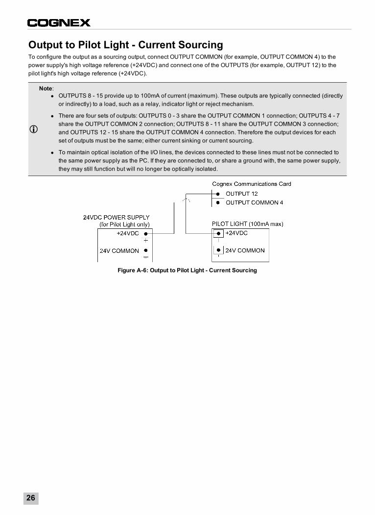
Output to Pilot Light - Current SourcingTo configure the output as a sourcing output, connect OUTPUT COMMON (for example, OUTPUT COMMON 4) to thepower supply's high voltage reference (+24VDC) and connect one of the OUTPUTS (for example, OUTPUT 12) to thepilot light's high voltage reference (+24VDC).
Note:l OUTPUTS 8 - 15 provide up to 100mA of current (maximum). These outputs are typically connected (directly
or indirectly) to a load, such as a relay, indicator light or reject mechanism.
l There are four sets of outputs: OUTPUTS 0 - 3 share the OUTPUT COMMON 1 connection; OUTPUTS 4 - 7share the OUTPUT COMMON 2 connection; OUTPUTS 8 - 11 share the OUTPUT COMMON 3 connection;and OUTPUTS 12 - 15 share the OUTPUT COMMON 4 connection. Therefore the output devices for eachset of outputs must be the same; either current sinking or current sourcing.
l To maintain optical isolation of the I/O lines, the devices connected to these lines must not be connected tothe same power supply as the PC. If they are connected to, or share a ground with, the same power supply,they may still function but will no longer be optically isolated.
Figure A-6: Output to Pilot Light - Current Sourcing
26

Differential Encoder ConfigurationFor a differential encoder, connect A+, B+, A- and B- to the corresponding encoder outputs. Connect the encoder'sground wire to ENCODER GROUND.
Note:l Non-quadrature, single-channel encoders are not supported.
l The frequency of encoder pulses must not exceed 50 kHz.
Figure A-7: Differential Encoder Configuration
Appendix A - Wire Inputs and Outputs
27

Single-Ended Encoder ConfigurationFor a single-ended encoder, connect A+ and B+ to the corresponding encoder outputs. Derive A- and B- from theencoder voltage source and make them equal to 50% of the encoder reference voltage (for example, if the encoder isconnected to 24VDC, set A- and B- to 12VDC). Connect the encoder's ground wire to ENCODER GROUND.
Note:l Non-quadrature, single-channel encoders are not supported.
l The frequency of encoder pulses must not exceed 50 kHz.
Figure A-8: Single-Ended Encoder Configuration
28


P/N INS-597-0064-01 Rev. A


![COGNEX in-Sight Product Guide[1]](https://img.dokumen.tips/doc/110x75/577cdbac1a28ab9e78a8c578/cognex-in-sight-product-guide1.jpg)


