Embed Size (px)
Citation preview
Cogeneration Performance Project October 23, 2014
UTSR Fellow: Xan Cranney, Brigham Young University
Industrial Mentor: Jeff Armstrong, FlexEnergy
1

1.Who is FlexEnergy?
2.UTSR Fellowship Project: Cogeneration
2
Agenda

1.Who is FlexEnergy?
2.UTSR Fellowship Project: Cogeneration
3
Agenda

OVERVIEW
FlexEnergy produces 250 and 333 kW gas-fired turbines
(over 3 million operating hours)
Developed by Ingersoll Rand as a derivative of the
Dresser-Rand KG2 (oilfield focused machine)
Flex offers the only “micro” turbine built like larger, more
robust turbine generators
Flex turbines use synchronous
generators, not high speed
alternators, providing
significantly more kVA &
transient load capability than
power electronics micro-
turbines
4
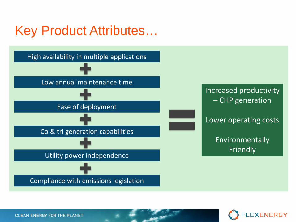
Key Product Attributes…
High availability in multiple applications
Low annual maintenance time
Ease of deployment
Co & tri generation capabilities
Utility power independence
Increased productivity – CHP generation
Lower operating costs
Environmentally
Friendly
Compliance with emissions legislation

FLEXENERGY TURBINE CYCLE DIAGRAM
1500/1800 rpm
45400 rpm
• 400/480 Volts • 50/60 Hz • 3 Phase
256ºC/493ºF Typical
Up to 913ºC/1675°F
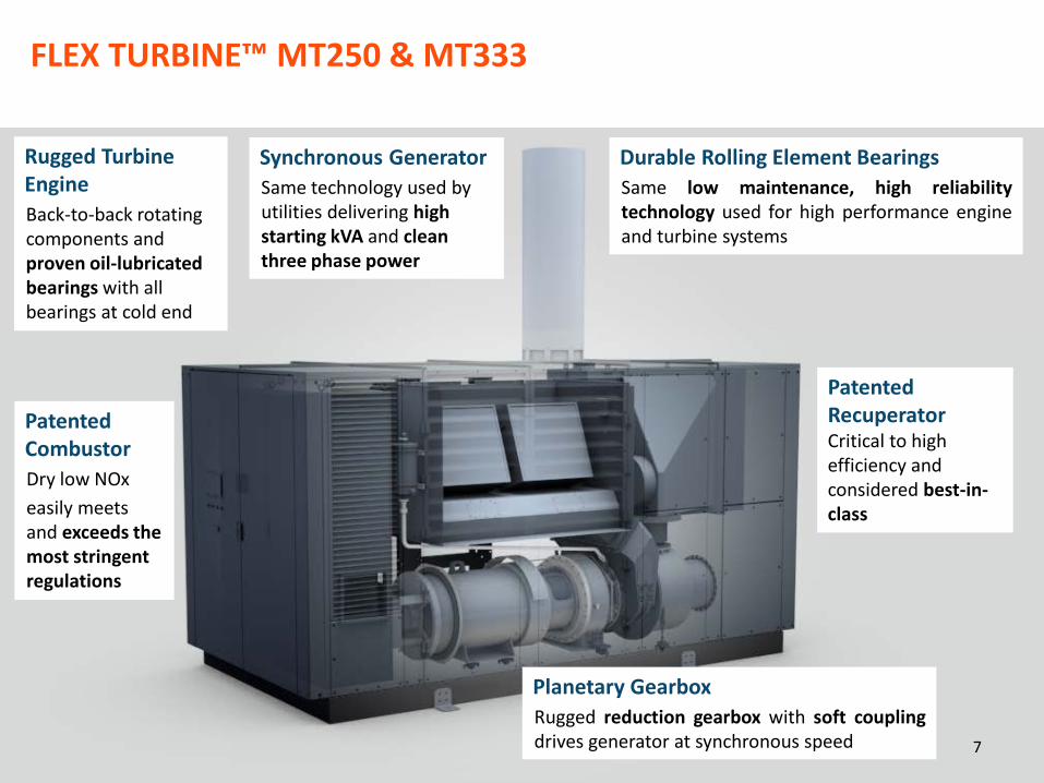
FLEX TURBINE™ MT250 & MT333
Rugged Turbine Engine Back-to-back rotating components and proven oil-lubricated bearings with all bearings at cold end
Patented Combustor Dry low NOx easily meets and exceeds the most stringent regulations
Patented Recuperator Critical to high efficiency and considered best-in-class
Durable Rolling Element Bearings Same low maintenance, high reliability technology used for high performance engine and turbine systems
Synchronous Generator Same technology used by utilities delivering high starting kVA and clean three phase power
Planetary Gearbox Rugged reduction gearbox with soft coupling drives generator at synchronous speed 7
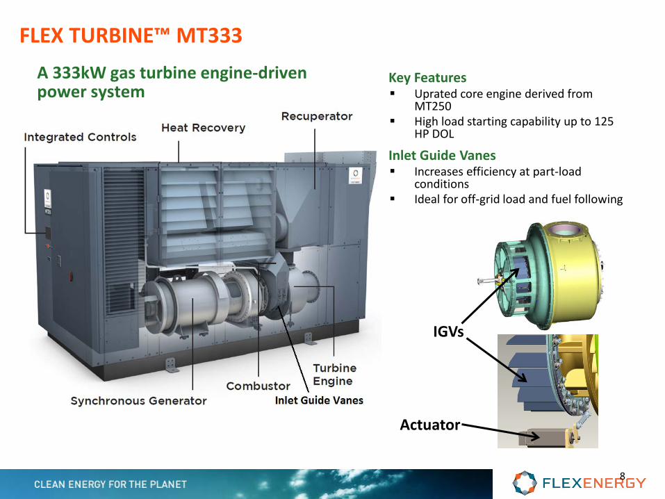
Key Features Uprated core engine derived from
MT250 High load starting capability up to 125
HP DOL
Inlet Guide Vanes Increases efficiency at part-load
conditions Ideal for off-grid load and fuel following
A 333kW gas turbine engine-driven power system
IGVs
Actuator
FLEX TURBINE™ MT333
8
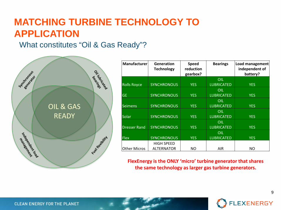
MATCHING TURBINE TECHNOLOGY TO APPLICATION
OIL & GAS READY
What constitutes “Oil & Gas Ready”?
Manufacturer Generation Technology
Speed reduction gearbox?
Bearings Load management independent of
battery?
Rolls Royce SYNCHRONOUS YES OIL
LUBRICATED YES
GE SYNCHRONOUS YES OIL
LUBRICATED YES
Seimens SYNCHRONOUS YES OIL
LUBRICATED YES
Solar SYNCHRONOUS YES OIL
LUBRICATED YES
Dresser Rand SYNCHRONOUS YES OIL
LUBRICATED YES
Flex SYNCHRONOUS YES OIL
LUBRICATED YES
Other Micros HIGH SPEED
ALTERNATOR NO AIR NO
FlexEnergy is the ONLY ‘micro’ turbine generator that shares the same technology as larger gas turbine generators.
9

Turbine Electrical Performance
Note: Does not include fuel gas booster parasitic Deduct 3.5% per 1000 ft (305 m)

Associated gas with “Heavies”
Associated gas with Diluents
Digester Gases
Landfill Gases
Requires N.G. to start
Fuel Lower Heating Value (Btu/ft3); dry basis at 14.7 psi (101 kPa) and 59F (15C)
H2S Tolerance of up to 6,500 ppmv / CO2 Content up to 70%
11

1.Who is FlexEnergy?
2.UTSR Fellowship Project: Cogeneration
12
Agenda

Motivation for Project • New MT333 has higher mass flow:
– Decrease ΔP of cogeneration heat exchanger – Maintain HX within turbine enclosure
• CHP Efficiency Incentives aggressive: – Public Utility Regulatory Policies Act (PURPA):
• Requires: (E+0.5Q)/LHV > 42.5% – California SGIP:
• Requires: (E+Q)/HHV > 60% (~66% LHV) – Massachusetts’ CHP Program initiative:
• Requires: (E+Q)/HHV > 60% (~66% LHV) – European Directive 2004/8/EC (2004.02.11):
• Requires: (E+Q)/LHV > 75% E = Electrical energy output, Q = Useful thermal energy
11/11/2014 13

Project Overview • Engineering Equation Solver (EES) heat exchanger model.
• Computational Fluid Dynamics
14 11/11/2014

NTU-ε Model
11/11/2014 15
Thermal circuit, Runit
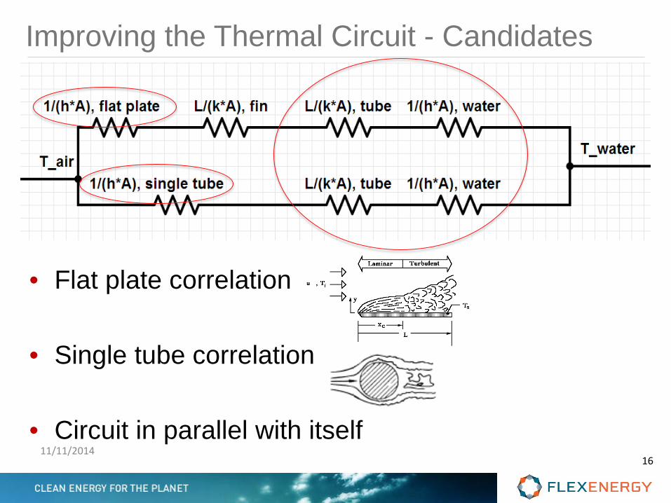
Improving the Thermal Circuit - Candidates
11/11/2014 16
• Flat plate correlation • Single tube correlation • Circuit in parallel with itself

Modified Thermal Circuit
• Tube correlation changed to Chilton-Colburn analogy of finned banks of tubes.
• No suitable replacements were found for flat plate correlation.
11/11/2014 17
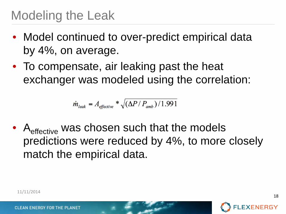
Modeling the Leak • Model continued to over-predict empirical data
by 4%, on average. • To compensate, air leaking past the heat
exchanger was modeled using the correlation:
• Aeffective was chosen such that the models predictions were reduced by 4%, to more closely match the empirical data.
11/11/2014 18

Empirical and Modeled Values
11/11/2014 19
Pred
icte
d Q̇
(Btu
/hr)
Measured Q̇ (Btu/hr)
PerfectCorrelation+ or - 10%

ΔTwater ΔTair
11/11/2014 20
Pred
icte
d Q̇
(Btu
/hr)
Measured Q̇ (Btu/hr)
PerfectCorrelation+ or - 10%

Energy Balance – A New Approach
11/11/2014 21

Empirical and Modeled Values
11/11/2014 22
Pred
icte
d Q̇
(Btu
/hr)
Measured Q̇ (Btu/hr)
Perfect Correlation
+ or - 10%

Project Overview • Engineering Equation Solver (EES) heat exchanger model.
• Computational Fluid Dynamics
23 11/11/2014

CFD Modeling • Realizable k-Epsilon • Mass flow Inlet • Pressure Outlet • HX — Porous, Laminar Zone • HX — Heat Sink • Color/arrow length depicts velocity • Over 50 Geometries tested
11/11/2014 24

Pressure Drop (ΔP) Calculations • ΔP data is proprietary • All ΔP data in this report are relative. They are
based off of the current cogen configuration • ΔP refers to total pressure • ΔP refers to ΔP across the entire geometry, excluding the HX.
11/11/2014 25
Current Cogen Configuration

Grid Independence Study • CFD models are not grid independent. • This table refers to percentage change of values
resulting from doubling the previous density.
• Most models in this report are “4x” grid density.
11/11/2014 26
2x 4x
Inlet ΔP -45% 29%
Outlet ΔP 32% 50%
Total non-HX ΔP -5% 42%
Current Cogen Configuration

3 Main Design Considerations
11/11/2014 27
Center Pivot ΔP = 45 Back Pivot, ΔP = 8 Front Pivot ΔP = 65
• The back/front pivot designs were rejected for two reasons: 1. High damper door torque 2. Undesired heat transfer when in “closed” position.
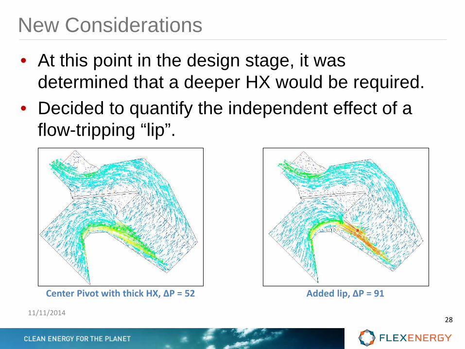
New Considerations • At this point in the design stage, it was
determined that a deeper HX would be required. • Decided to quantify the independent effect of a
flow-tripping “lip”.
11/11/2014 28
Center Pivot with thick HX, ΔP = 52 Added lip, ΔP = 91
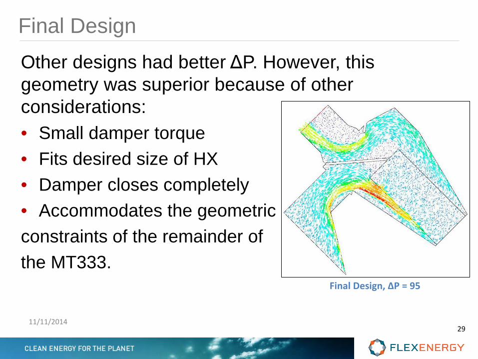
Final Design Other designs had better ΔP. However, this geometry was superior because of other considerations: • Small damper torque • Fits desired size of HX • Damper closes completely • Accommodates the geometric constraints of the remainder of the MT333.
11/11/2014 29
Final Design, ΔP = 95
Conclusion As a result of the UTSR fellowship, a number of objectives were achieved: • The HX model was refined and calibrated • ΔP was predicted for various geometries • A final HX size was selected • A final cogen geometry was designed
11/11/2014 30
Acknowledgements • FlexEnergy, Inc. • UTSR Fellowship Program • Special Thanks to
– Jeffrey Armstrong, Chris Bolin, John Alday, Nikolai Kozulin, Corey Bergeron, Mike Carney, Tom Hackett, Bob Megee, Brian Finstad, and Greg Arbo, all of FlexEnergy.
– Dr. Steven Gorrell, Brigham Young University
11/11/2014 31
Questions? • If I don’t know the answer, then I reserve the
right to pretend that it’s proprietary information.
11/11/2014 32