Embed Size (px)
Citation preview

1
COFFERDAM SOLUTION FOR STEEPLY SLOPING ROCK
USING FLAT SHEET-PILES
Robert Bittner, P.E., Bittner-Shen Consulting Engineers, Inc., Portland, Oregon
Norm Kirk, P.E. Independent Consultant, Boulder, Colorado
The addition of a new powerhouse at the existing Tulloch Hydroelectric site on the Stanislaus River in the western foothills of the Sierras Nevada Mountains of central California required a deep excavation in rock on the downstream face of the dam. A cofferdam (water exclusion device) was necessary to isolate the powerhouse construction site excavation from the existing Goodwin Reservoir and the turbulent discharge from the existing powerhouse. The cofferdam was positioned on a steeply sloping fractured rock surface exceeding 50 degrees.
This paper describes the challenges encountered during design and construction of the cofferdam and describes the unique design features used to address these challenges including:
• The use of flat-sheet-piles to form cellular walls on the steeply sloping rock surface.
• The use of 5-ft deep tremie concrete plugs in the bottom of the sheet pocket cells to create the bottom seal of the cellular cofferdam walls against the sloping rock surface.
• The use of vertical post-tensioned rock anchors to provide shear resistance at the contact point between the base of the cellular-wall and the sloping rock surface.
INTRODUCTION
Modification or expansion of existing hydro-electric power plants often require downstream cofferdams or water exclusion devices to temporarily separate new construction from turbulent downstream discharge of the existing dam. Most dams are positioned on solid rock in the narrowest and therefore the steepest section of the river. This combination of steeply sloping- rock and the need for an exclusion barrier creates a challenge for the design engineer trying to maintain a safe dewatered construction site. Typical cofferdam solutions for hydroelectric dams usually use large granular filled circular sheet pile cells that perform as gravity structures. However, this type of structures is not well suited to steeply-sloping highly irregular rock surfaces in a confined area.

2
PROPOSED DESIGN SOLUTION
At the Tulloch Hydro site, the required footprint of the cofferdam was a U-shaped structure positioned on the down-slope rock face below the dam. See Photo 1 of the fractured sloping rock face below the dam and Figure 1 for a plan view of the proposed cofferdam. Figure 2 provides a transverse section of the cofferdam in the downslope direction. The cofferdam design was tailored to address the following specific challenges:
1. Sealing along the base of the U-shaped cofferdam at the interface between the Z-sheets and the top of rock.
2. Sealing up the sides of the U-shaped cofferdam at the interface between the bottom of the cellular box sheets and the steeply upward-sloping rock face.
3. Horizontal resistance at the base of the Z-sheets. 4. Horizontal resistance at the base of the cellular box sheets. 5. Resisting uplift at bottom of cofferdam.
Photo 1 - Sloping rock face below dam prior to installation of cofferdam

3
Figure 1 – Cofferdam Plan View

4
Figure 2 – Section A
SEALING AT BASE OF Z-SHEETS
Conventional Z-sheet piles were selected for the offshore wall of the cofferdam that ran roughly parallel to the shore and formed the base of the U-shape of the cofferdam shown in Figure 1. Since the rock sloped in the offshore direction, this wall was in the deepest part of the cofferdam, and this increased depth along the full length of wall allowed the use of a thin tremie slab to be placed. This tremie slab served two purposes: it cut off water flow from the offshore direction and it provided support at the bottom of the Z-sheet piles against the 32-ft hydrostatic design head of the cofferdam. However, the thin tremie slab created another problem, which was the hydrostatic uplift on the tremie slab and how to overcome it.
SEALING AT BASE OF CELLULAR BOX SHEETS
The two end walls of the U-shaped cofferdam were built using flat-sheet piles configured in cellular boxes. See Figure 3 for a plan view detail of the cellular boxes. The relatively narrow flat sheets conformed sufficiently to the highly irregular steeply sloping rock surface to allow

5
placement of tremie concrete in each cellular pocket. The purpose of the tremie concrete was to form a bottom seal between the toe of the sheet piles and the sloping irregular rock. Retention of the relatively fluid tremie concrete in the sheet pile cellular pockets was achieved by pre-trimming the bottom of the sheets to conform to the rock slope and by using 16-in. diameter polyester woven fabric bags filled with grout. See Figure 4 for a detail of how these bags were placed and held in position during grout placement prior to tremie concrete infill of the cellular sheet pockets. See Figure 5 for a detail of the wale frame seated into the sloping rock face.
Figure 3 – Detail A

6
Figure 4 – Section B

7
Figure 5 – Section C
HORIZONTAL RESISTANCE AT BASE OF Z-SHEETS
The three sided cofferdam was designed to resist the 32-ft hydrostatic design head at two levels. The upper support was provided by a conventional wale frame with diagonal struts positioned above water at 2-ft below the top of wall. Bottom support for the offshore Z-sheet wall was provided by the 4-ft vertical surface of the tremie slab. Prior to placement of the tremie concrete, rock anchors were pre-installed on fixed spacing to provide added sliding resistance against the hydrostatic reaction at the bottom of the Z-sheets and prevent the tremie slab from being pushed up the sloping rock subgrade. See Figure 1 for a layout of the tremie slab and rock anchors. See Figure 2 for a section through the cofferdam with a detail of the rock anchors.
HORIZONTAL RESISTANCE AT BASE OF CELLULAR BOX SHEETS
Due to the limited depth of the tremie concrete and the upward slope of the rocks, the tremie slab did not cover the entire base of the cofferdam. Consequently, there was no tremie slab to provide bottom restraint along most of the two cellular side walls of the cofferdam and an alternate bottom support was needed for these two walls to resist the hydrostatic load. This bottom restraint was provided by placing the sheet pile cells in vertical compression through the
8
use of stressed rock anchors. See Figure 3 for a plan view of the anchor top termination and Figure 4 for a section of the bottom termination.
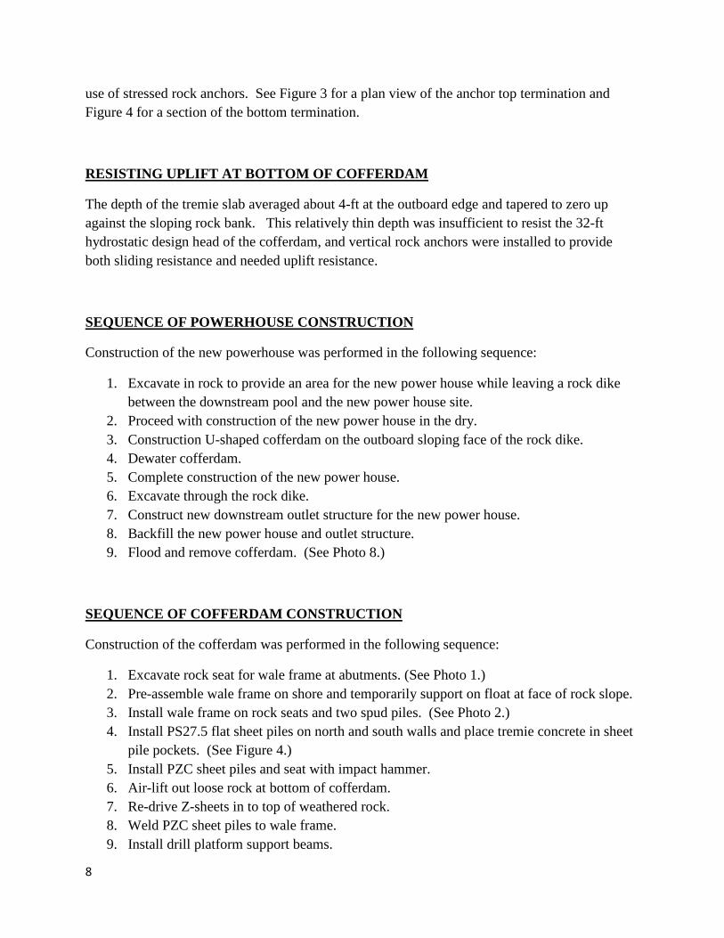
RESISTING UPLIFT AT BOTTOM OF COFFERDAM
The depth of the tremie slab averaged about 4-ft at the outboard edge and tapered to zero up against the sloping rock bank. This relatively thin depth was insufficient to resist the 32-ft hydrostatic design head of the cofferdam, and vertical rock anchors were installed to provide both sliding resistance and needed uplift resistance.
SEQUENCE OF POWERHOUSE CONSTRUCTION
Construction of the new powerhouse was performed in the following sequence:
1. Excavate in rock to provide an area for the new power house while leaving a rock dike between the downstream pool and the new power house site.
2. Proceed with construction of the new power house in the dry. 3. Construction U-shaped cofferdam on the outboard sloping face of the rock dike. 4. Dewater cofferdam. 5. Complete construction of the new power house. 6. Excavate through the rock dike. 7. Construct new downstream outlet structure for the new power house. 8. Backfill the new power house and outlet structure. 9. Flood and remove cofferdam. (See Photo 8.)
SEQUENCE OF COFFERDAM CONSTRUCTION
Construction of the cofferdam was performed in the following sequence:
1. Excavate rock seat for wale frame at abutments. (See Photo 1.) 2. Pre-assemble wale frame on shore and temporarily support on float at face of rock slope. 3. Install wale frame on rock seats and two spud piles. (See Photo 2.) 4. Install PS27.5 flat sheet piles on north and south walls and place tremie concrete in sheet
pile pockets. (See Figure 4.) 5. Install PZC sheet piles and seat with impact hammer. 6. Air-lift out loose rock at bottom of cofferdam. 7. Re-drive Z-sheets in to top of weathered rock. 8. Weld PZC sheet piles to wale frame. 9. Install drill platform support beams.

9
10. Drill and install rock anchors at base of cofferdam. 11. Place tremie concrete bottom seal. 12. Grout foundation rock. 13. Dewater cofferdam. 14. Cut-off anchor bars at top of tremie seal.
CONCLUSION
The cofferdam was successfully dewatered and remained dry during construction of the new power house and removal of the rock dike separating the downstream pool from the completed power house. See Photos 3, 4, 5, 6, and 7 for views of the cofferdam during various phases of construction. See Photo 8 for a view of the completed new outlet structure positioned at the site of the removed cofferdam. The cofferdam design and installation methods described in this paper were an efficient and cost effective solution for the sloping irregular rock surfaces encountered at the Tulloch Hydro site.
Photo 2 - Setting cofferdam frame

10
Photo 3 - Cofferdam tie into sloping rock face
Photo 4 - Aerial view of cofferdam prior to removal of rock dike

11
Photo 5 - Dewatered cofferdam prior to removal of rock dike
Photo 6 - View from inside cofferdam after removal of rock dike

12
Photo 7 - View of cofferdam from inside power house
after removal of rock dike
Photo 8 - Finished outlet structure from new power unit


![COFFERDAM [Compatibility Mode]](https://img.dokumen.tips/doc/110x75/577cdecf1a28ab9e78afe28b/cofferdam-compatibility-mode.jpg)