Embed Size (px)
Citation preview

CODING THE ARDUINO
WAY
Muhammad Adeel Javaid

Table of Contents
Reading a Potentiometer (analog input) ......................................................................... 2 Code .............................................................................................................................. 2
The "Hello World!" of Physical Computing ................................................................... 4
Code .............................................................................................................................. 4
Blinking an LED without using the delay() function ...................................................... 6
Code ................................................................................................................................ 6
Pushbutton....................................................................................................................... 9 Switch ........................................................................................................................... 11
Circuit ........................................................................................................................ 11
Code ............................................................................................................................ 11
Interfacing a Joystick .................................................................................................... 13 Knock Sensor ................................................................................................................ 16
Representing the Knock in Processing ........................................................ 17
Memsic 2125 Accelerometer ........................................................................................ 19
PING range finder ................................................................................................. 22
Play Melody .................................................................................................................. 24
Example 1: Play Melody ...................................................................................... 24
Keyboard Serial ............................................................................................................ 29
LCD Display - 8 bits ..................................................................................................... 31 Unipolar Stepper Motor ................................................................................................ 34
Example 1: Simple example .............................................................................. 34
Example 2: Stepper Unipolar Advanced ...................................................... 35
References................................................................................................................ 37

PREFACE
Arduino is an open-source, programmable microcontroller and software based on the ATMega chip.
Although the Arduino is designed as a prototyping platform, it can be used in various electronics projects
whether temporary or embedded. The Arduino board can be programmed using the Arduino software. The
syntax for this is similar to C/C++ and Java. It is designed to be simple and easy to use, and can be
operated by anyone, from beginners to experts alike.
As Arduino is an open source platform, you can get hold of the source code and schematics for it. This
means you can delve as far into it as you want, even creating your own Arduino boards. There is also a
large community behind it, and you can find many tutorials and projects from all over the world online.
The main features of an Arduino board are it’s ability to read data from sensors, to send and receive
digital signals and can connect via serial to your computer. You can control many things, from LEDs and
LCDs, to motors and relays. You can also read values from sensors such as potentiometers, light
dependant resistors (LDRs) and piezos.
The digital pins on an Arduino allow you to read or write 5v values. You can use a pin to turn on an LED
(with a resistor). You can send a signal to a relay to operate higher voltage appliances like televisions and
house lights. You can send messages to motors to turn on and off. You can check to see if a button has
been pressed. You can even send and receive serial data, parallel data and digital pulse width modulation.
Basically anything that can be controlled via a bit of current can be used.
The analog pins allow you to read an incoming voltage between 0v and 5v. This will be how you read from
sensors. There are a multitude of sensors available, from simple hands-on pressure sensors and
rotary potentiometers, to environment sensors such as pressure, gas, temperature and even alcohol. If
you have, for example, a slider set to exactly half of its range, it should output a voltage of 2.5v. The
Arduino can then read this and use the value to control something else.
You don’t have to stop with just controlling electronic circuits. You can send data back to the computer to
control software such as Processing and Max/MSP. You can send the data over USB with most models.
Some models have Bluetooth and Ethernet ports, and with an additional shields (like an add-on unit) you
can communicate via WiFi and other protocols.
The Arduino doesn’t have a lot of processing power, so pretty much any major intensive task is out of the
question. You won’t be able to process, record or output video or audio (Although you can output graphics
to TFT or LCD screens). It is not like a computer. You won’t be able to hook up your webcam or keyboard
to it. There is no operating system with a GUI (like a Raspberry Pi). It is a completely different beast.
The beauty of Arduino is that even if you have no knowledge or experience with electronics or
programming, you can get a simple project up and running in an hour or two. Getting an LED to flash on
and off in a pattern is as simple as adding an LED and resistor to a breadboard, connecting a few wires
and writing a few lines of code. Arduinos are used in classrooms all over the world as a starter to
programming and electronics.
1
Reading a Potentiometer (analog input)
A potentiometer is a simple knob that provides a variable resistance, which we can read into the Arduino
board as an analog value. In this example, that value controls the rate at which an LED blinks.
We connect three wires to the Arduino board. The first goes to ground from one of the outer pins of the
potentiometer. The second goes from 5 volts to the other outer pin of the potentiometer. The third goes from
analog input 2 to the middle pin of the potentiometer.
By turning the shaft of the potentiometer, we change the amount of resistence on either side of the wiper which
is connected to the center pin of the potentiometer. This changes the relative "closeness" of that pin to 5 volts
and ground, giving us a different analog input. When the shaft is turned all the way in one direction, there are 0
volts going to the pin, and we read 0. When the shaft is turned all the way in the other direction, there are 5
volts going to the pin and we read 1023. In between, analogRead() returns a number between 0 and 1023 that is
proportional to the amount of voltage being applied to the pin.
Code /* Analog Read to LED * ------------------
*
* turns on and off a light emitting diode(LED) connected to digital * pin 13. The amount of time the LED will be on and off depends on * the value obtained by analogRead(). In the easiest case we connect * a potentiometer to analog pin 2. * * Created 1 December 2005 * copyleft 2005 DojoDave <http://www.0j0.org> * http://arduino.berlios.de * */
2

int potPin = 2; // select the input pin for the potentiometer
int ledPin = 13; // select the pin for the LED int val = 0; // variable to store the value coming from the
sensor void setup() {
pinMode(ledPin, OUTPUT); // declare the ledPin as an OUTPUT
}
void loop() { // read the value from the sensor
val = analogRead(potPin);
digitalWrite(ledPin, HIGH); // turn the ledPin on
delay(val); // stop the program for some time
digitalWrite(ledPin, LOW); // turn the ledPin off
delay(val); // stop the program for some time
}
3

The "Hello World!" of Physical Computing
The first program every programmer learns consists in writing enough code to make their code show the
sentence "Hello World!" on a screen.
As a microcontroller, Arduino doesn't have any pre-established output devices. Willing to provide newcomers with
some help while debugging programs, we propose the use of one of the board's pins plugging a LED that we will
make blink indicating the right functionallity of the program.
We have added a 1K resistor to pin 13, what allows the immediate connection of a LED between that pin and
ground.
LEDs have polarity, which means they will only light up if you orient the legs properly. The long leg is typically
positive, and should connect to pin 13. The short leg connects to GND; the bulb of the LED will also typically have
a flat edge on this side. If the LED doesn't light up, trying reversing the legs (you won't hurt the LED if you plug it
in backwards for a short period of time).
Code
The example code is very simple, credits are to be found in the comments. /* Blinking LED * ------------
*
* turns on and off a light emitting diode(LED) connected to a digital * pin, in intervals of 2 seconds. Ideally we use pin 13 on the Arduino * board because it has a resistor attached to it, needing only an LED
* * Created 1 June 2005
4

* copyleft 2005 DojoDave <http://www.0j0.org> * http://arduino.berlios.de
*
* based on an orginal by H. Barragan for the Wiring i/o
board */
int ledPin = 13; // LED connected to digital pin 13
void setup()
{ // sets the digital pin as output
pinMode(ledPin, OUTPUT);
}
void loop()
{ // sets the LED on
digitalWrite(ledPin, HIGH);
delay(1000); // waits for a second
digitalWrite(ledPin, LOW); // sets the LED off
delay(1000); // waits for a second
}
5

Blinking an LED without using the delay() function.
Sometimes you need to blink an LED (or some other time sensitive function) at the same time as something else
(like watching for a button press). That means you can't use delay(), or you'd stop everything else the program
while the LED blinked. Here's some code that demonstrates how to blink the LED without using delay(). It keeps
track of the last time it turned the LED on or off. Then, each time through loop() it checks if a sufficient interval
has passed - if it has, it turns the LED off if it was on and vice-versa.
Code
/* Blinking LED without using delay * turns on and off a light emitting diode(LED) connected to a digital * pin, without using the delay() function. this means that other code * can run at the same time without being interrupted by the LED code. * Created 14 February 2006
*/ int ledPin = 13; // LED connected to digital pin 13
int value = LOW; // previous value of the LED
long previousMillis = 0; // will store last time LED was updated
long interval = 1000; // interval at which to blink
(milliseconds)
void setup()
{ // sets the digital pin as output
pinMode(ledPin, OUTPUT);
}
void loop()
{
// here is where you'd put code that needs to be running all
the time.
// check to see if it's time to blink the LED; that is, is
the difference
// between the current time and last time we blinked the LED bigger than
// the interval at which we want to blink the LED. if (millis() - previousMillis > interval) {
previousMillis = millis(); // remember the last time we blinked
the LED
// if the LED is off turn it on and vice-
versa. if (value == LOW) value =
HIGH; else value = LOW;
digitalWrite(ledPin, value);
} }
6

/* * Code for cross-fading 3 LEDs, red, green and blue, or one tri-color LED, using PWM * The program cross-fades slowly from red to green, green to blue, and blue to red
* The debugging code assumes Arduino 0004, as it uses the new Serial.begin()-style functions
* Clay Shirky <[email protected]> */ // Output int redPin = 9;
int greenPin = 10;
int bluePin = 11;
// Red LED, connected to digital pin 9 // Green LED, connected to digital pin 10 // Blue LED, connected to digital pin 11
// Program variables int redVal = 255; // Variables to store the values to send to the
pins int greenVal = 1; // Initial values are Red full, Green and Blue off
int blueVal = 1; int i = 0; // Loop counter int wait = 50; // 50ms (.05 second) delay; shorten for faster fades
int DEBUG = 0; // DEBUG counter; if set to 1, will write values
back via serial void setup()
{ OUTPUT); // sets the pins as output
pinMode(redPin,
pinMode(greenPin, OUTPUT);
pinMode(bluePin, OUTPUT);
if (DEBUG) { // If we want to see the pin values for
debugging...
Serial.begin(9600); // ...set up the serial ouput on 0004 style }
} // Main program
void loop() {
// Increment counter
i += 1;
if (i < 255) // First phase of fades
{ -= 1; // Red down
redVal
greenVal += 1; // Green up
blueVal = 1; // Blue low
}
else if (i < 509) // Second phase of fades {
= 1; // Red low
redVal
greenVal -= 1; // Green down
blueVal += 1; // Blue up
}
else if (i < 763) // Third phase of fades {
redVal += 1; // Red up
greenVal = 1; // Green low
7

blueVal -= 1; // Blue down } else // Re-set the counter, and start the fades again {
i = 1;
}
analogWrite(redPin, redVal); // Write current values to LED pins
analogWrite(greenPin, greenVal);
analogWrite(bluePin, blueVal);
if (DEBUG) { // If we want to read the output
DEBUG += 1; // Increment the DEBUG counter
if (DEBUG > 10) // Print every 10 loops
{
// Reset the counter
DEBUG = 1;
Serial.print(i); // Serial commands in 0004 style
Serial.print("\t"); // Print a tab
Serial.print("R:"); // Indicate that output is red value
Serial.print(redVal); // Print red value
Serial.print("\t"); // Print a tab
Serial.print("G:"); // Repeat for green and blue...
Serial.print(greenVal); Serial.print("\t"); Serial.print("B:"); Serial.println(blueVal); // println, to end with a
carriage return }
} delay(wait); // Pause for 'wait' milliseconds before resuming
the loop }
8

Pushbutton
The pushbutton is a component that connects two points in a circuit when you press it. The example turns on
an LED when you press the button.
We connect three wires to the Arduino board. The first goes from one leg of the pushbutton through a pull-up
resistor (here 2.2 KOhms) to the 5 volt supply. The second goes from the corresponding leg of the pushbutton to
ground. The third connects to a digital i/o pin (here pin 7) which reads the button's state.
When the pushbutton is open (unpressed) there is no connection between the two legs of the pushbutton, so the
pin is connected to 5 volts (through the pull-up resistor) and we read a HIGH. When the button is closed
(pressed), it makes a connection between its two legs, connecting the pin to ground, so that we read a LOW.
(The pin is still connected to 5 volts, but the resistor in-between them means that the pin is "closer" to ground.)
/* Basic Digital Read * ------------------
*
* turns on and off a light emitting diode(LED) connected to digital * pin 13, when pressing a pushbutton attached to pin 7. It
illustrates the * concept of Active-Low, which consists in connecting buttons using a * 1K to 10K pull-up resistor. * * Created 1 December 2005 * copyleft 2005 DojoDave <http://www.0j0.org> * http://arduino.berlios.de * */
int ledPin = 13; // choose the pin for the LED int inPin = 7; // choose the input pin (for a pushbutton) int val = 0; // variable for reading the pin status
9

void setup() { // declare LED as output
pinMode(ledPin, OUTPUT);
pinMode(inPin, INPUT); // declare pushbutton as input
}
void loop(){ val = digitalRead(inPin); // read input value if (val == HIGH) { // check if the input is HIGH (button
released) digitalWrite(ledPin, LOW); // turn LED OFF
} else { digitalWrite(ledPin, HIGH); // turn LED ON
} }
10

Switch
This example demonstrates the use of a pushbutton as a switch: each time you press the button, the LED (or
whatever) is turned on (if it's off) or off (if on). It also debounces the input, without which pressing the
button once would appear to the code as multiple presses.
Circuit
A push-button on pin 2 and an LED on pin 13.
Code /* switch * * Each time the input pin goes from LOW to HIGH (e.g. because of
a push-button
* press), the output pin is toggled from LOW to HIGH or HIGH to LOW. There's * a minimum delay between toggles to debounce the circuit (i.e.
to ignore
* noise). * * David A. Mellis
* 21 November
2006 */ int inPin = 2; // the number of the input pin int outPin = 13; // the number of the output pin int state = HIGH; // the current state of the output pin int reading; // the current reading from the input pin int previous = LOW; // the previous reading from the input pin
11

// the follow variables are long's because the time, measured
in miliseconds, // will quickly become a bigger number than can be stored in an
int. long time = 0; // the last time the output pin was toggled
long debounce = 200; // the debounce time, increase if the output
flickers void setup() {
if (DEBUG)
Serial.begin(19200);
pinMode(inPin, INPUT);
pinMode(outPin, OUTPUT); } void loop() {
reading = digitalRead(inPin);
// if the input just went from LOW and HIGH and we've waited
long enough // to ignore any noise on the circuit, toggle the output pin
and remember
// the time if (reading == HIGH && previous == LOW && millis() - time > debounce)
{ if (state == HIGH)
state = LOW; else
state = HIGH;
time = millis(); }
digitalWrite(outPin, state);
previous = reading;
}
12
Interfacing a Joystick
The Joystick Schematic
13

How this works
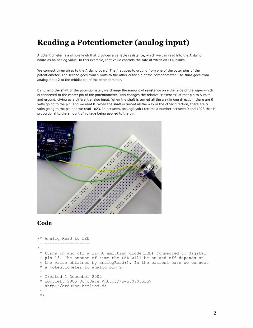
The joystick in the picture is nothing but two potentiometers that allow us to messure the movement of the
stick in 2-D. Potentiometers are variable resistors and, in a way, they act as sensors providing us with a
variable voltage depending on the rotation of the device around its shaft.
The kind of program that we need to monitor the joystick has to make a polling to two of the analog pins. We
can send these values back to the computer, but then we face the classic problem that the transmission over the
communication port has to be made with 8bit values, while our DAC (Digital to Analog Converter - that is
messuring the values from the potentiometers in the joystick) has a resolution of 10bits. In other words this
means that our sensors are characterized with a value between 0 and 1024.
The following code includes a method called treatValue() that is transforming the sensor's messurement into a
value between 0 and 9 and sends it in ASCII back to the computer. This allows to easily send the information
into e.g. Flash and parse it inside your own code.
Finally we make the LED blink with the values read from the sensors as a direct visual feedback of how we
control the joystick. /* Read Jostick * ------------
*
* Reads two analog pins that are supposed to be * connected to a jostick made of two potentiometers
*
* We send three bytes back to the comp: one header and two * with data as signed bytes, this will take the form: * Jxy\r\n * * x and y are integers and sent in ASCII
*
* http://www.0j0.org | http://arduino.berlios.de * copyleft 2005 DojoDave for DojoCorp */
int ledPin = 13;
14
int joyPin1 = 0; // slider variable connecetd to
analog pin 0 // slider variable connecetd to
int joyPin2 = 1;
analog pin 1 // variable to read the value from
int value1 = 0;
the analog pin 0 // variable to read the value from
int value2 = 0;
the analog pin 1
void setup() { // initializes digital pins 0
pinMode(ledPin, OUTPUT);
to 7 as outputs
beginSerial(9600);
}
int treatValue(int data) {
return (data * 9 / 1024) + 48;
}
void loop() {
// reads the value of the variable
resistor value1 = analogRead(joyPin1); // this small pause is needed between reading // analog pins, otherwise we get the same value
twice delay(100);
// reads the value of the variable resistor value2 = analogRead(joyPin2);
digitalWrite(ledPin, HIGH);
delay(value1);
digitalWrite(ledPin, LOW);
delay(value2); serialWrite('J');
serialWrite(treatValue(value1));
serialWrite(treatValue(value2));
serialWrite(10); serialWrite(13); }
15

Knock Sensor
Here we use a Piezo element to detect sound, what will allow us to use it as a knock sensor. We are taking
advantage of the processors capability to read analog signals through its ADC - analog to digital converter. These
converters read a voltage value and transform it into a value encoded digitally. In the case of the Arduino
boards, we transform the voltage into a value in the range 0..1024. 0 represents 0volts, while 1024 represents
5volts at the input of one of the six analog pins.
A Piezo is nothing but an electronic device that can both be used to play tones and to detect tones. In our
example we are plugging the Piezo on the analog input pin number 0, that supports the functionality of reading a
value between 0 and 5volts, and not just a plain HIGH or LOW.
The other thing to remember is that Piezos have polarity, commercial devices are usually having a red and a
black wires indicating how to plug it to the board. We connect the black one to ground and the red one to the
input. We also have to connect a resistor in the range of the Megaohms in parallel to the Piezo element; in the
example we have plugged it directly in the female connectors. Sometimes it is possible to acquire Piezo elements
without a plastic housing, then they will just look like a metallic disc and are easier to use as input sensors.
The code example will capture the knock and if it is stronger than a certain threshold, it will send the string
"Knock!" back to the computer over the serial port. In order to see this text you could either use a terminal
program, which will read data from the serial port and show it in a window, or make your own program in e.g.
Processing. Later in this article we propose a program that works for the software designed by Reas and Fry.
Example of connection of a Piezo to analog pin 0 with a resistor /* Knock Sensor
16

* ---------------- *
* Program using a Piezo element as if it was a knock sensor. *
* We have to basically listen to an analog pin and detect * if the signal goes over a certain threshold. It writes * "knock" to the serial port if the Threshold is crossed, * and toggles the LED on pin 13. * * (cleft) 2005 D. Cuartielles for
K3 */ int ledPin = 13;
int knockSensor =
0; byte val = 0; int statePin = LOW;
int THRESHOLD = 100; void setup() {
pinMode(ledPin, OUTPUT);
beginSerial(9600); } void loop() {
val = analogRead(knockSensor);
if (val >= THRESHOLD) { statePin = !statePin;
digitalWrite(ledPin, statePin);
printString("Knock!");
printByte(10); printByte(13);
} delay(100); // we have to make a delay to avoid overloading the
serial port }
Representing the Knock in Processing
If, e.g. we would like to capture this "knock" from the Arduino board, we have to look into how the information
is transferred from the board over the serial port. First we see that whenever there is a knock bigger that the
threshold, the program is printing (thus sending) "Knock!" over the serial port. Directly after sends the byte 10,
what stands for EOLN or End Of LiNe, and byte 13, or CR - Carriage Return. Those two symbols will be useful to
determine when the message sent by the board is over. Once that happens, the processing program will toggle
the background color of the screen and print out "Knock!" in the command line. // Knock In // by David Cuartielles <http://www.0j0.org> // based on Analog In by Josh Nimoy <http://itp.jtnimoy.com>
// Reads a value from the serial port and makes the background // color toggle when there is a knock on a piezo used as a knock // sensor. // Running this example requires you have an Arduino board // as peripheral hardware sending values and adding an EOLN + CR
17

// in the end. More information can be found on the Arduino // pages: http://www.arduino.cc
// Created 23 November 2005 // Updated 23 November 2005 import processing.serial.*; String buff =
""; int val = 0; int NEWLINE = 10; Serial port; void setup() {
size(200, 200);
// Open your serial port port = new Serial(this, "COMXX", 9600); // <-- SUBSTITUTE COMXX with
your serial port name!! } void draw() {
// Process each one of the serial port
events while (port.available() > 0) { serialEvent(port.read());
} background(val);
} void serialEvent(int serial) {
if(serial != NEWLINE) {
buff += char(serial); } else {
buff = buff.substring(1, buff.length()-1); // Capture the string and print it to the commandline // we have to take from position 1 because // the Arduino sketch sends EOLN (10) and CR (13) if (val == 0)
{ val = 255; } else {
val = 0; } println(buff); // Clear the value of
"buff" buff = ""; }
} 18

Memsic 2125 Accelerometer
The Memsic 2125 is a dual axis accelerometer sensor from Parallax able of measuring up to a 2g acceleration.
When making very accurate measurements, the sensor counts with a temperature pin that can be used to
compensate possible errors.
The pins dedicated to measure acceleration can be connected directly to digital inputs to the Arduino board, while
the the temperature should be taken as an analog input. The acceleration pins send the signals back to the
computer in the form of pulses which width represents the acceleration.
The example shown here was mounted by Anders Gran, while the software was created by Marcos Yarza, who is
Arduino's accelerometer technology researcher, at the University of Zaragoza, Spain. The board is connected
minimally, only the two axis pins are plugged to the board, leaving the temperature pin open.
Protoboard with an Accelerometer, picture by Anders Gran /* Accelerometer Sensor
* -------------------- *
* Reads an 2-D accelerometer * attached to a couple of digital inputs and * sends their values over the serial port; makes * the monitor LED blink once sent * * * http://www.0j0.org
19
* copyleft 2005 K3 - Malmo University - Sweden * @author: Marcos Yarza * @hardware: Marcos Yarza * @project: SMEE - Experiential Vehicles * @sponsor: Experiments in Art and Technology Sweden, 1:1
Scale */ int ledPin = 13;
int xaccPin = 7;
int yaccPin = 6;
int value = 0;
int accel = 0;
char sign = ' '; int timer = 0;
int count = 0; void setup() { beginSerial(9600); // Sets the baud rate to
9600 pinMode(ledPin, OUTPUT); pinMode(xaccPin, INPUT);
pinMode(yaccPin, INPUT); } /* (int) Operate Acceleration * function to calculate acceleration * returns an integer */ int operateAcceleration(int time1) {
return abs(8 * (time1 / 10 - 500)); } /* (void) readAccelerometer * procedure to read the sensor, calculate * acceleration and represent the
value */
void readAcceleration(int
axe){ timer = 0; count = 0;
value = digitalRead(axe);
while(value == HIGH) { // Loop until pin reads a
low value = digitalRead(axe);
}
while(value == LOW) { // Loop until pin reads a
high value = digitalRead(axe);
}
while(value == HIGH) { // Loop until pin reads a low and
count value = digitalRead(axe);
count = count + 1;
}
timer = count * 18; //calculate the teme in miliseconds
//operate sign if (timer > 5000){
sign = '+'; } if (timer < 5000){
20

sign = '-'; } //determine the value accel = operateAcceleration(timer); //Represent acceleration over serial
port if (axe == 7){ printByte('X'); } else {
printByte('Y'); } printByte(sign); printInteger(accel);
printByte(' '); } void loop() { readAcceleration(xaccPin); //reads and represents acceleration
X readAcceleration(yaccPin); //reads and represents
acceleration Y digitalWrite(ledPin, HIGH); delay(300);
digitalWrite(ledPin, LOW); } Accelerometer mounted on prototyping board, by M. Yarza
The following example is an adaptation of the previous one. Marcos Yarza added two 220Ohm resistors to the
pins coming out of the accelerometer. The board chosen for this small circuit is just a piece of prototyping
board. Here the code is exactly the same as before (changing the input pins to be 2 and 3), but the installation
on the board allows to embed the whole circutry in a much smaller housing. 21

PING range finder
The PING range finder is an ultrasound sensor from Parallax able of detecting objects up to a 3 mts distance. The
sensor counts with 3 pins, two are dedicated to power and ground, while the third one is used both as input and
output.
The pin dedicated to make the readings has to be shifting configuration from input to output according to the
PING specification sheet. First we have to send a pulse that will make the sensor send an ultrasound tone and
wait for an echo. Once the tone is received back, the sensor will send a pulse over the same pin as earlier. The
width of that pulse will determine the distance to the object.
The example shown here was mounted by Marcus Hannerstig, while the software was created by David
Cuartielles. The board is connected as explained using only wires coming from an old computer.
Ultrasound sensor connected to an Arduino USB v1.0 /* Ultrasound Sensor * Reads values (00014-01199) from an ultrasound sensor (3m sensor) * and writes the values to the serialport.
* http://www.xlab.se | http://www.0j0.org * copyleft 2005 Mackie for XLAB | DojoDave for DojoCorp
*/ int ultraSoundSignal = 7; // Ultrasound signal
pin int val = 0; int ultrasoundValue = 0; int timecount = 0; // Echo counter int ledPin = 13; // LED connected to digital pin 13
22
void setup() {
// Sets the baud rate to 9600
beginSerial(9600);
pinMode(ledPin, OUTPUT); // Sets the digital pin as output
}
void loop() {
timecount =
0; val = 0; pinMode(ultraSoundSignal, OUTPUT); // Switch signalpin to output
/* Send low-high-low pulse to activate the trigger pulse of
the sensor*/ digitalWrite(ultraSoundSignal, LOW); // Send low pulse
delayMicroseconds(2); // Wait for 2 microseconds
digitalWrite(ultraSoundSignal, HIGH); // Send high
pulse delayMicroseconds(5); // Wait for 5 microseconds
digitalWrite(ultraSoundSignal, LOW); // Holdoff /* Listening for echo pulse*/ pinMode(ultraSoundSignal, INPUT); // Switch signalpin to input
val = digitalRead(ultraSoundSignal); // Append signal value to
val while(val == LOW) { // Loop until pin reads a high value val = digitalRead(ultraSoundSignal);
} while(val == HIGH) { // Loop until pin reads a high value
val = digitalRead(ultraSoundSignal); // Count echo pulse time
timecount = timecount +1;
}
/* Writing out values to the serial port*/ ultrasoundValue = timecount; // Append echo pulse time
to ultrasoundValue serialWrite('A'); // Example identifier for the
sensor printInteger(ultrasoundValue); serialWrite(10); serialWrite(13); /* Lite up LED if any value is passed by the echo pulse*/ if(timecount > 0){
digitalWrite(ledPin, HIGH); } /* Delay of program*/ delay(100); }
23

Play Melody
This example makes use of a Piezo Speaker in order to play melodies. We are taking advantage of the
processors capability to produde PWM signals in order to play music. There is more information about how PWM
works written by David Cuartielles here and even at K3's old course guide
A Piezo is nothing but an electronic device that can both be used to play tones and to detect tones. In our
example we are plugging the Piezo on the pin number 9, that supports the functionality of writing a PWM
signal to it, and not just a plain HIGH or LOW value.
The first example of the code will just send a square wave to the piezo, while the second one will make use of
the PWM functionality to control the volume through changing the Pulse Width.
The other thing to remember is that Piezos have polarity, commercial devices are usually having a red and a
black wires indicating how to plug it to the board. We connect the black one to ground and the red one to the
output. Sometimes it is possible to acquire Piezo elements without a plastic housing, then they will just look like a
metallic disc.
Example of connection of a Piezo to pin 9
Example 1: Play Melody /* Play Melody * -----------
*
* Program to play a simple melody 24

* * Tones are created by quickly pulsing a speaker on and off * using PWM, to create signature frequencies. * * Each note has a frequency, created by varying the period of * vibration, measured in microseconds. We'll use pulse-width
* modulation (PWM) to create that vibration.
* We calculate the pulse-width to be half the period; we pulse * the speaker HIGH for 'pulse-width' microseconds, then LOW
* for 'pulse-width' microseconds.
* This pulsing creates a vibration of the desired frequency.
*
* (cleft) 2005 D. Cuartielles for K3 * Refactoring and comments 2006 [email protected] * See NOTES in comments at end for possible improvements */
// TONES ========================================== // Start by defining the relationship between // note, period, & frequency.
#define c 3830 // 261 Hz #define d 3400 // 294 Hz #define e 3038 // 329 Hz #define f 2864 // 349 Hz #define g 2550 // 392 Hz #define a 2272 // 440 Hz #define b 2028 // 493 Hz #define C 1912 // 523 Hz // Define a special note, 'R', to represent a rest
#define R 0 // SETUP ============================================ // Set up speaker on a PWM pin (digital 9, 10 or 11) int speakerOut = 9;
// Do we want debugging on serial out? 1 for yes, 0 for
no int DEBUG = 1; void setup() {
pinMode(speakerOut,
OUTPUT); if (DEBUG) { Serial.begin(9600); // Set serial out if we want debugging
} } // MELODY and TIMING ======================================= // melody[] is an array of notes, accompanied by beats[],
// which sets each note's relative length (higher #, longer note)
int melody[] = { C, b, g, C, b, e, R, C, c, g, a, C }; int beats[] = { 16, 16, 16, 8, 8, 16, 32, 16, 16, 16, 8, 8 };
int MAX_COUNT = sizeof(melody) / 2; // Melody length, for looping. // Set overall tempo
long tempo = 10000;
// Set length of pause between
notes int pause = 1000;
// Loop variable to increase Rest length 25

int rest_count = 100; //<-BLETCHEROUS HACK; See NOTES // Initialize core
variables int tone = 0; int beat = 0;
long duration = 0;
// PLAY TONE ============================================== // Pulse the speaker to play a tone for a particular
duration void playTone() {
long elapsed_time = 0;
if (tone > 0) { // if this isn't a Rest beat, while the tone has
// played less long than 'duration', pulse speaker HIGH and
LOW while (elapsed_time < duration) {
digitalWrite(speakerOut,HIGH);
delayMicroseconds(tone / 2);
// DOWN
digitalWrite(speakerOut, LOW);
delayMicroseconds(tone / 2);
// Keep track of how long we
pulsed elapsed_time += (tone); }
} else { // Rest beat; loop times delay
for (int j = 0; j < rest_count; j++) { // See NOTE on
rest_count delayMicroseconds(duration); }
} } // LET THE WILD RUMPUS BEGIN ============================= void loop() {
// Set up a counter to pull from melody[] and
beats[] for (int i=0; i<MAX_COUNT; i++) { tone = melody[i];
beat = beats[i];
duration = beat * tempo; // Set up timing
playTone(); // A pause between notes... delayMicroseconds(pause);
if (DEBUG) { // If debugging, report loop, tone, beat, and
duration Serial.print(i); Serial.print(":"); Serial.print(beat); Serial.print(" "); Serial.print(tone); Serial.print(" ");
Serial.println(duration); }
} }
26

/* * NOTES * The program purports to hold a tone for 'duration' microseconds. * Lies lies lies! It holds for at least 'duration'
microseconds, _plus_
* any overhead created by incremeting elapsed_time (could be
in excess of * 3K microseconds) _plus_ overhead of looping and two digitalWrites()
*
* As a result, a tone of 'duration' plays much more slowly than a rest * of 'duration.' rest_count creates a loop variable to bring
'rest' beats * in line with 'tone' beats of the same length.
* * rest_count will be affected by chip architecture and speed, as well
as
* overhead from any program mods. Past behavior is no guarantee
of future * performance. Your mileage may vary. Light fuse and get away.
* * This could use a number of enhancements: * ADD code to let the programmer specify how many times the
melody should * loop before stopping
* ADD another octave * MOVE tempo, pause, and rest_count to #define statements * RE-WRITE to include volume, using analogWrite, as with the
second program at * http://www.arduino.cc/en/Tutorial/PlayMelody
* ADD code to make the tempo settable by pot or other input device * ADD code to take tempo or volume settable by serial communication * (Requires 0005 or higher.)
* ADD code to create a tone offset (higer or lower) through pot etc * REPLACE random melody with opening bars to 'Smoke on the
Water' */
Second version, with volume control set using analogWrite() /* Play Melody * -----------
*
* Program to play melodies stored in an array, it requires to know * about timing issues and about how to play tones. * * The calculation of the tones is made following the mathematical * operation: * * timeHigh = 1/(2 * toneFrequency) = period / 2
*
* where the different tones are described as in the table: *
* note frequency period PW (timeHigh)
* c 261 Hz 3830 1915
27

* d 294 Hz 3400 1700 * e 329 Hz 3038 1519 * f 349 Hz 2864 1432 * g 392 Hz 2550 1275 * a 440 Hz 2272 1136 * b 493 Hz 2028 1014 * C 523 Hz 1912 956 * * (cleft) 2005 D. Cuartielles for
K3 */ int ledPin = 13;
int speakerOut = 9; byte names[] = {'c', 'd', 'e', 'f', 'g', 'a', 'b', 'C'}; int tones[] = {1915, 1700, 1519, 1432, 1275, 1136, 1014, 956}; byte
melody[] = "2d2a1f2c2d2a2d2c2f2d2a2c2d2a1f2c2d2a2a2g2p8p8p8p"; // count length: 1 2 3 4 5 6 7 8 9 0 1 2 3 4 5 6 7 8 9 0 1 2 3 4 5 6 7 8 9 0
10 20
//
30
int count = 0;
int count2 = 0;
int count3 = 0; int MAX_COUNT = 24;
int statePin = LOW; void setup() {
pinMode(ledPin, OUTPUT); } void loop() {
analogWrite(speakerOut, 0); for (count = 0; count < MAX_COUNT; count++)
{ statePin = !statePin; digitalWrite(ledPin, statePin); for (count3 = 0; count3 <= (melody[count*2] - 48) * 30; count3++)
{ for (count2=0;count2<8;count2++) { if (names[count2] == melody[count*2 + 1])
{ analogWrite(speakerOut,500);
delayMicroseconds(tones[count2]);
analogWrite(speakerOut, 0);
delayMicroseconds(tones[count2]); } if (melody[count*2 + 1] == 'p') {
// make a pause of a certain
size analogWrite(speakerOut, 0);
delayMicroseconds(500); }
} }
} }
28

Keyboard Serial
This example makes use of a Piezo Speaker in order to play tones. We are taking advantage of the
processors capability to produde PWM signals in order to play music. There is more information about how
PWM works written by David Cuartielles here and even at K3's old course guide
A Piezo is nothing but an electronic device that can both be used to play tones and to detect tones. In our
example we are plugging the Piezo on the pin number 9, that supports the functionality of writing a PWM
signal to it, and not just a plain HIGH or LOW value.
The tones can be lauched using any program able of sending ascii values over the serial port. Terminal software
packages, Processing, Pure Data, Director, or the serial proxy + Flash combination can be used to launch the
tones.
Example of connection of a Piezo to pin 9 /* Keyboard Serial * ----------------
*
* Program to play tones depending on the * data coming from the serial port.
*
* The calculation of the tones is made following the mathematical * operation: * * timeHigh = 1/(2 * toneFrequency) = period / 2
29

* * where the different tones are described as in the table: *
frequency period PW (timeHigh)
* note
* c 261 Hz 3830 1915
* d 294 Hz 3400 1700
* e 329 Hz 3038 1519
* f 349 Hz 2864 1432
* g 392 Hz 2550 1275
* a 440 Hz 2272 1136
* b 493 Hz 2028 1014
* C 523 Hz 1912 956
*
* (cleft) 2005 D. Cuartielles for
K3 */ int ledPin = 13;
int speakerOut = 9; byte names[] ={'c', 'd', 'e', 'f', 'g', 'a', 'b', 'C'}; int tones[] = {1915, 1700, 1519, 1432, 1275, 1136, 1014,
956}; byte val = 0; int serByte = -1;
int statePin = LOW;
int count = 0; void setup() {
pinMode(ledPin, OUTPUT);
pinMode(speakerOut,
OUTPUT); beginSerial(9600); } void loop() {
digitalWrite(speakerOut,
LOW); serByte = serialRead(); if (serByte != -1) { val
= serByte;
printByte(val);
statePin = !statePin; digitalWrite(ledPin, statePin);
} for (count=0;count<=8;count++)
{ if (names[count] == val) { digitalWrite(speakerOut, HIGH);
delayMicroseconds(tones[count]);
digitalWrite(speakerOut, LOW);
delayMicroseconds(tones[count]); }
} }
30

LCD Display - 8 bits
This example shows the most basic action to be done with a LCD display: to show a welcome message. In our
case we have an LCD display with backlight and contrast control. Therefore we will use a potentiometer to
regulate the contrast.
LCD displays are most of the times driven using an industrial standard established by Hitachi. According to it
there is a group of pins dedicated to sending data and locations of that data on the screen, the user can choose
to use 4 or 8 pins to send data. On top of that three more pins are needed to synchronize the communication
towards the display.
The backdrop of this example is that we are using almost all the available pins on Arduino board in order to drive
the display, but we have decided to show it this way for simplicity.
Picture of a protoboard supporting the display and a potentiometer /* LCD Hola * --------
*
* This is the first example in how to use an LCD screen * configured with data transfers over 8 bits. The example * uses all the digital pins on the Arduino board, but can * easily display data on the display * * There are the following pins to be considered: *
31

* - DI, RW, DB0..DB7, Enable (11 in total) *
* the pinout for LCD displays is standard and there is plenty * of documentation to be found on the internet. * * (cleft) 2005 DojoDave for K3 * */
int DI = 12;
int RW = 11; int DB[] = {3, 4, 5, 6, 7, 8, 9,
10}; int Enable = 2; void LcdCommandWrite(int value) { // poll all the
pins int i = 0;
for (i=DB[0]; i <= DI; i++)
{ digitalWrite(i,value &
01); value >>= 1; }
digitalWrite(Enable,LOW);
delayMicroseconds(1);
// send a pulse to enable
digitalWrite(Enable,HIGH); delayMicroseconds(1); // pause 1 ms according to datasheet
digitalWrite(Enable,LOW);
delayMicroseconds(1); // pause 1 ms according to datasheet } void LcdDataWrite(int value) { // poll all the pins int
i = 0; digitalWrite(DI,
HIGH); digitalWrite(RW,
LOW); for (i=DB[0]; i <= DB[7]; i++)
{ digitalWrite(i,value & 01);
value >>= 1; }
digitalWrite(Enable,LOW);
delayMicroseconds(1);
// send a pulse to enable
digitalWrite(Enable,HIGH);
delayMicroseconds(1);
digitalWrite(Enable,LOW); delayMicroseconds(1); // pause 1 ms according to datasheet
} void setup (void)
{ int i = 0; for (i=Enable; i <= DI; i++)
{ pinMode(i,OUTPUT); } delay(100); // initiatize lcd after a short pause // needed by the LCDs controller
LcdCommandWrite(0x30); // function set:
32

delay(64); // 8-bit interface, 1 display lines, 5x7 font
// function set:
LcdCommandWrite(0x30);
delay(50); // 8-bit interface, 1 display lines, 5x7 font
// function set:
LcdCommandWrite(0x30);
delay(20); // 8-bit interface, 1 display lines, 5x7 font
// entry mode set:
LcdCommandWrite(0x06);
delay(20); // increment automatically, no display shift
// display control:
LcdCommandWrite(0x0E);
delay(20); // turn display on, cursor on, no blinking
// clear display, set cursor position to zero
LcdCommandWrite(0x01);
delay(100); // display control:
LcdCommandWrite(0x80);
delay(20); // turn display on, cursor on, no blinking
}
void loop (void) { LcdCommandWrite(0x02); // set cursor position to zero
delay(10); // Write the welcome
message LcdDataWrite('H');
LcdDataWrite('o');
LcdDataWrite('l');
LcdDataWrite('a');
LcdDataWrite(' ');
LcdDataWrite('C');
LcdDataWrite('a');
LcdDataWrite('r');
LcdDataWrite('a');
LcdDataWrite('c');
LcdDataWrite('o');
LcdDataWrite('l');
LcdDataWrite('a');
delay(500); }
33

Unipolar Stepper Motor
This page shows two examples on how to drive a unipolar stepper motor. These motors can be found in old
floppy drives and are easy to control. The one we use has 6 connectors of which one is power (VCC) and
the other four are used to drive the motor sending synchronous signals.
The first example is the basic code to make the motor spin in one direction. It is aiming those that have no
knowledge in how to control stepper motors. The second example is coded in a more complex way, but allows to
make the motor spin at different speeds, in both directions, and controlling both from a potentiometer.
The prototyping board has been populated with a 10K potentiomenter that we connect to an analog input, and a
ULN2003A driver. This chip has a bunch of transistors embedded in a single housing. It allows the connection of
devices and components that need much higher current than the ones that the ATMEGA8 from our Arduino
board can offer.
Picture of a protoboard supporting the ULN2003A and a potentiometer
Example 1: Simple example /* Stepper Copal * -------------
*
* Program to drive a stepper motor coming from a 5'25 disk drive * according to the documentation I found, this stepper: "[...] motor * made by Copal Electronics, with 1.8 degrees per step and 96 ohms * per winding, with center taps brought out to separate leads [...]"
34

* [http://www.cs.uiowa.edu/~jones/step/example.html] * * It is a unipolar stepper motor with 5 wires:
*
* - red: power connector, I have it at 5V and works fine * - orange and black: coil 1 * - brown and yellow: coil 2 * * (cleft) 2005 DojoDave for K3 * http://www.0j0.org | http://arduino.berlios.de
*
* @author: David Cuartielles * @date: 20 Oct. 2005 */
int motorPin1 = 8;
int motorPin2 = 9;
int motorPin3 = 10;
int motorPin4 = 11;
int delayTime = 500; void setup() {
pinMode(motorPin1, OUTPUT);
pinMode(motorPin2, OUTPUT);
pinMode(motorPin3, OUTPUT);
pinMode(motorPin4, OUTPUT); } void loop() {
digitalWrite(motorPin1, HIGH);
digitalWrite(motorPin2, LOW);
digitalWrite(motorPin3, LOW);
digitalWrite(motorPin4, LOW);
delay(delayTime);
digitalWrite(motorPin1, LOW);
digitalWrite(motorPin2, HIGH);
digitalWrite(motorPin3, LOW);
digitalWrite(motorPin4, LOW);
delay(delayTime);
digitalWrite(motorPin1, LOW);
digitalWrite(motorPin2, LOW);
digitalWrite(motorPin3, HIGH);
digitalWrite(motorPin4, LOW);
delay(delayTime);
digitalWrite(motorPin1, LOW);
digitalWrite(motorPin2, LOW);
digitalWrite(motorPin3, LOW);
digitalWrite(motorPin4, HIGH);
delay(delayTime); }
Example 2: Stepper Unipolar Advanced 35

/* Stepper Unipolar Advanced * -------------------------
*
* Program to drive a stepper motor coming from a 5'25 disk drive * according to the documentation I found, this stepper: "[...] motor * made by Copal Electronics, with 1.8 degrees per step and 96 ohms * per winding, with center taps brought out to separate leads [...]" * [http://www.cs.uiowa.edu/~jones/step/example.html] * * It is a unipolar stepper motor with 5 wires:
*
* - red: power connector, I have it at 5V and works fine * - orange and black: coil 1 * - brown and yellow: coil 2 * * (cleft) 2005 DojoDave for K3 * http://www.0j0.org | http://arduino.berlios.de
*
* @author: David Cuartielles * @date: 20 Oct. 2005 */
int motorPins[] = {8, 9, 10,
11}; int count = 0; int count2 = 0; int delayTime =
500; int val = 0; void setup() {
for (count = 0; count < 4; count++) {
pinMode(motorPins[count], OUTPUT); }
} void moveForward() {
if ((count2 == 0) || (count2 == 1))
{ count2 = 16; } count2>>=1; for (count = 3; count >= 0; count--) {
digitalWrite(motorPins[count], count2>>count&0x01); } delay(delayTime);
} void moveBackward() {
if ((count2 == 0) || (count2 == 1))
{ count2 = 16; } count2>>=1; for (count = 3; count >= 0; count--) {
digitalWrite(motorPins[3 - count], count2>>count&0x01); } delay(delayTime);
} void loop() {
36

val = analogRead(0);
if (val > 540) { // move faster the higher the value from the
potentiometer delayTime = 2048 - 1024 * val / 512 + 1; moveForward();
} else if (val < 480) {
// move faster the lower the value from the
potentiometer delayTime = 1024 * val / 512 + 1; moveBackward();
} else { delayTime = 1024;
} }
References
In order to work out this example, we have been looking into quite a lot of documentation. The following links
may be useful for you to visit in order to understand the theory underlying behind stepper motors:
- information about the motor we are using - here
- basic explanation about steppers - here
- good PDF with basic information - here
37