Embed Size (px)
Citation preview
ABB Jokab Safety Varlabergsvägen 11, SE-434 39 Kungsbacka, Sweden
www.abb.com/jokabsafety
Original instructions
Eden OSSD Coded non-contact safety sensor
2TLC172272M0201 Rev B 2 www.abb.com/jokabsafety
2015-08-22
Read and understand this document
Please read and understand this document before using the products. Please consult your ABB JOKAB SAFETY
representative if you have any questions or comments.
WARRANTY
ABB JOKAB SAFETY’s exclusive warranty is that the products are free from defects in materials and workmanship for a period of one year (or other period if specified) from date of sale by ABB JOKAB SAFETY.
ABB JOKAB SAFETY MAKES NO WARRANTY OR REPRESENTATION, EXPRESSED OR IMPLIED, REGARDING NON-INFRINGEMENT, MERCHANTABILITY, OR FITNESS FOR PARTICULAR PURPOSE OF THE PRODUCTS, ANY BUYER OR USER ACKNOWLEDGES THAT THE BUYER OR USER ALONE HAS DETERMINED THAT THE PRODUCTS WILL SUITABLY MEET THE REQUIREMENTS OR THEIR INTENDED USE. ABB JOKAB SAFETY DISCLAIMS ALL OTHER WARRANTIES, EXPRESSED OR IMPLIED.
LIMITATIONS OF LIABILITY
ABB JOKAB SAFETY SHALL NOT BE RESPONSIBLE FOR SPECIAL, INDIRECT, OR CONSEQUENTIAL DAMAGES, LOSS OF PROFITS OR COMMERCIAL LOSS IN ANY WAY CONNECTED WITH THE PRODUCTS, WHETHER SUCH CLAIM IS BASED ON CONTRACT, WARRANTY, NEGLIGENCE, OR STRICT LIABILITY.
In no event shall responsibility of ABB JOKAB SAFETY for any act exceed the individual price of the product on which liability asserted.
IN NO EVENT SHALL ABB JOKAB SAFETY BE RESPONSIBLE FOR WARRANTY, REPAIR, OR OTHER CLAIMS REGARDING THE PRODUCTS UNLESS ABB JOKAB SAFETY’S ANALYSIS CONFIRMS THAT THE PRODUCTS WERE PROPERLY HANDLED, STORED, INSTALLED, AND MAINTAINED AND NOT SUBJECT TO ABUSE, MISUSE, OR INAPPROPRIATE MODIFICATION OR REPAIR.
SUITABILITY FOR USE
ABB JOKAB SAFETY shall not be responsible for conformity with any standards, codes, or regulations that apply to the combination of products in the customer’s application or use of the product. At the customer’s request, ABB JOKAB SAFETY will provide applicable third party certification documents identifying ratings and limitations of use that apply to the products. This information by itself is not sufficient for a complete determination of the suitability of the products in combination with the end product, machine, system, or other application or use.
The following are some examples of applications for which particular attention must be given. This is not intended to be an exhaustive list of all possible uses of the products, nor is it intended to imply that the uses listed may be suitable for the products:
Outdoor use, uses involving potential chemical contamination or electrical interference, or conditions or uses not described in this document.
Nuclear energy control systems, combustion systems, railroad systems, aviation systems, medical equipment, amusement machines, vehicles, and installations subject to separate industry or government regulations.
Systems, machines, and equipment that could present a risk to life or property.
Please know and observe all prohibitions of use applicable to the products.
NEVER USE THE PRODUCTS FOR AN APPLICATION INVOLVING SERIOUS RISK TO LIFE OR PROPERTY WITHOUT ENSURING THAT THE SYSTEM AS A WHOLE HAS BEEN DESIGNED TO ADDRESS THE RISKS, AND THAT THE ABB JOKAB SAFETY PRODUCT IS PROPERLY RATED AND INSTALLED FOR THE INTENDED USE WITHIN THE OVERALL EQUIPMENT OR SYSTEM.
PERFORMANCE DATA
While every effort has been taken to ensure the accuracy of the information contained in this manual ABB JOKAB SAFETY cannot accept responsibility for errors or omissions and reserves the right to make changes and improvements without notice. Performance data given in this document is provided as a guide for the user in determining suitability and does not constitute a warranty. It may represent the result of ABB JOKAB SAFETY’S test conditions, and the users must correlate it to actual application requirements. Actual performance is subject to the ABB JOKAB SAFETY Warranty and Limitations of Liability.

2TLC172272M0201 Rev B 3 www.abb.com/jokabsafety
2015-08-22
Table of Contents
1 Introduction ......................................................................................................................................... 5
Scope ............................................................................................................................................................................ 5
Audience ....................................................................................................................................................................... 5
Prerequisites ................................................................................................................................................................. 5
Special notes ................................................................................................................................................................. 5
2 Overview .............................................................................................................................................. 6
General description ....................................................................................................................................................... 6
Safety regulations ......................................................................................................................................................... 6
3 Models of Adam and Eva .................................................................................................................... 7
Adam OSSD .................................................................................................................................................................. 7
Eva ................................................................................................................................................................................ 7
4 Electrical connections......................................................................................................................... 8
Adam OSSD-Info M12-8 ............................................................................................................................................... 8
Adam OSSD-Reset M12-8 ............................................................................................................................................ 8
Adam OSSD-Info M12-5 ............................................................................................................................................... 9
Adam OSSD-Reset M12-5 ............................................................................................................................................ 9
Connection of cable C5, C8 in M12 C01-C04 connectors .......................................................................................... 10
Information output signal attributes ............................................................................................................................. 10
Connection of Reset button on Adam OSSD-Reset ................................................................................................... 11
5 Connection examples ....................................................................................................................... 14
Adam OSSD-Info connected to RT9 ........................................................................................................................... 14
Several Adam OSSD-Info connected in series ........................................................................................................... 14
6 Installation ......................................................................................................................................... 15
General information ..................................................................................................................................................... 15
Minimum safety distance ............................................................................................................................................. 15
Detection distance ....................................................................................................................................................... 16
Mounting ...................................................................................................................................................................... 17
Mounting procedure: ................................................................................................................................................... 18
Teaching the code ....................................................................................................................................................... 19
How to erase existing codes from Adam M12-5 ......................................................................................................... 19
How to erase existing codes from Adam M12-8 ......................................................................................................... 19
Replacing Eva ............................................................................................................................................................. 20
Testing the safety functions ........................................................................................................................................ 20
7 LED indication ................................................................................................................................... 21
8 Maintenance ....................................................................................................................................... 22
Troubleshooting .......................................................................................................................................................... 22
9 Model overview .................................................................................................................................. 23

2TLC172272M0201 Rev B 4 www.abb.com/jokabsafety
2015-08-22
Accessories ................................................................................................................................................................. 23
Cables ......................................................................................................................................................................... 24
10 Technical data ................................................................................................................................... 25
Guideline for chemical resistance ............................................................................................................................... 27
Eden dimensions ......................................................................................................................................................... 28
CAD model .................................................................................................................................................................. 28
11 EC Declaration of conformity ........................................................................................................... 29

2TLC172272M0201 Rev B 5 www.abb.com/jokabsafety
2015-08-22
1 Introduction
Scope
The purpose of these instructions is to describe the non-contact coded digital safety sensor Eden OSSD and to
provide the necessary information required for installation and operation.
Audience
This document is intended for authorized installation personnel.
Prerequisites
It is assumed that the reader of this document has knowledge of the following:
Basic knowledge of ABB Jokab Safety products.
Knowledge of machine safety.
Special notes
Pay attention to the following special notes in the document:
Warning!
Danger of severe personal injury!
An instruction or procedure which, if not carried out correctly, may result in injury to the operator or other personnel.
Caution! Danger of damage to the equipment!
An instruction or procedure which, if not carried out correctly, may damage the equipment.
NB: Notes are used to provide important or explanatory information.

2TLC172272M0201 Rev B 6 www.abb.com/jokabsafety
2015-08-22
2 Overview
General description
Eden OSSD sensor consists of two separate devices – Adam and Eva – intended to use as interlocking device for
gates, hatches etc. Eva can be general coded or unique coded.
Eden OSSD meets the coding requirements according to EN ISO 14119:2013 regarding manipulation protection.
Safety regulations
Warning!
Carefully read through this entire manual before using the device.
The devices shall be installed by a trained electrician following applicable safety regulations, standards and the
Machine directive.
Failure to comply with instructions, operation that is not in accordance with the use prescribed in these instructions,
improper installation or handling of the device can affect the safety of people and the plant.
For installation and prescribed use of the product, the special notes in the instructions must be carefully observed and
the technical standards relevant to the application must be considered.
In case of failure to comply with the instructions or standards, especially when tampering with and/or modifying the
product, any liability is excluded.

2TLC172272M0201 Rev B 7 www.abb.com/jokabsafety
2015-08-22
3 Models of Adam and Eva
Eden communicates with OSSD signals and can be connected to any safety module that handles OSSD-signals. Up
to 30 Eden sensors can be connected in series without reducing the achieved performance level. Adam and Eva are
acquired separately and it is possible to mix different models of Adam OSSD in the same safety circuit.
Adam OSSD
Adam OSSD exists in four different models:
Adam OSSD-Info M12-8
OSSD model with information output and inputs for cascade connection.
Adam OSSD-Reset M12-8
OSSD model with built in monitored reset, indication lamp output and
inputs for cascade connection.
Adam OSSD-Info M12-5
OSSD model with information output.
Adam OSSD-Reset M12-5
OSSD model with built in monitored reset and indication lamp output.
Eva
Eva exists in two different models. The Eva units with general code have all the same code. The Eva units with unique
code have all a different unique code. The unique variant fulfils the requirements for a high level coded interlocking
device according to EN ISO 14119:2013. The Eva with general code fulfils the requirement for a low level coded
interlocking device. It is possible to mix different models of Eva in the same safety circuit.
Eva General code
Eva with the same code.
Eva Unique code
Eva with a unique code.

2TLC172272M0201 Rev B 8 www.abb.com/jokabsafety
2015-08-22
4 Electrical connections
Adam OSSD-Info M12-8
Adam OSSD-Reset M12-8
M12-connector:
(8-pole male)
1) White: OSSD signal 1 Out
2) Brown: +24 VDC
3) Green: OSSD signal 1 In
4) Yellow: OSSD signal 2 In
5) Grey: Information
6) Pink: OSSD signal 2 Out
7) Blue: 0 V
8) Red: Information
M12 8-pole male
from cable side
M12 8-pole female
from cable side
M12-connector:
(8-pole male)
1) White: OSSD signal 1 Out
2) Brown: +24 VDC
3) Green: OSSD signal 1 In
4) Yellow: OSSD signal 2 In
5) Grey: Reset/Indication
6) Pink: OSSD signal 2 Out
7) Blue: 0 V
8) Red: Information
M12 8-pole male
from cable side
M12 8-pole female
from cable side

2TLC172272M0201 Rev B 9 www.abb.com/jokabsafety
2015-08-22
Adam OSSD-Info M12-5
Adam OSSD-Reset M12-5
NB: The use of shielded cable is mandatory between Adam OSSD and the rest of the safety circuit.
Caution! All cable colours according to ABB Jokab Safety standard cables.
M12-connector:
(5-pole male)
1) Brown: +24 VDC
2) White: OSSD signal 1 Out
3) Blue: 0 V
4) Black: OSSD signal 2 Out
5) Grey Information
M12 5-pole male
from cable side
M12 5-pole female
from cable side
M12-connector:
(5-pole male)
1) Brown: +24 VDC
2) White: OSSD signal 1 Out
3) Blue: 0 V
4) Black: OSSD signal 2 Out
5) Grey Reset/Indication
M12 5-pole male
from cable side
M12 5-pole female
from cable side

2TLC172272M0201 Rev B 10 www.abb.com/jokabsafety
2015-08-22
Connection of cable C5, C8 in M12 C01-C04 connectors
Female 5-pin connector (M12 C01):
Male 5-pin connector (M12 C02):
Female 8-pin connector (M12 C03):
Male 8-pin connector (M12 C04):
Information output signal attributes
Adam OSSD-Info is equipped with an information output on pin 5 and pin 8. The information outputs on pin 5 and
pin 8 are set high (+24 VDC) when the OSSD-outputs are set high, otherwise they are set low.
The maximum current consumption for the information output is 15 mA.
Warning! The information output signal is not a failsafe signal and should never be used for the safety purpose(s).
1 ) Brown
2 ) White
3 ) Blue
4 ) Black
5 ) Grey
1 ) White
2 ) Brown
3 ) Green
4 ) Yellow
5 ) Grey
6 ) Pink
7 ) Blue
8 ) Red

2TLC172272M0201 Rev B 11 www.abb.com/jokabsafety
2015-08-22
Connection of Reset button on Adam OSSD-Reset
Adam OSSD-Reset is a model prepared for monitored local reset. A reset light button can be connected to pin 5 and
Adam OSSD handles the monitored reset and the indication lamp of the reset button. Each Eden with a local reset
can be reset individually and independently of the others. Only when all Eden units in the safety circuit have been
reset, the safety circuit itself is reset and the machine can be restarted.
Any button with a NO-contact and an indication lamp can be used. See electrical connection below. The maximum
current consumption for the indication lamp is 30 mA. Smile 12RF and Smile 12RG are reset buttons with indication
lamps from ABB Jokab Safety indented to be used together with Adam OSSD-Reset.
The reset signal is accepted as valid only when the reset signal is high for more than 100 ms but less than 3 s.
Reset indication lamp status Description
On: No valid Eva is detected, safety circuit is open.
Flash (0.4 s ON / 0.6 s OFF): Valid Eva is detected. Waiting for reset.
Off: The reset button has been pressed and the safety circuit is closed.
Warning! Several Eden must not be connected in parallel to a common reset button. Each Eden must be separately
connected to a local reset.

2TLC172272M0201 Rev B 12 www.abb.com/jokabsafety
2015-08-22
Serial connection of three Adam OSSD-Reset M12-8 through M12-3G with Smile 12RG to a
safety relay, Pluto or another safety-PLC (i.e. ABB AC500-S).

2TLC172272M0201 Rev B 13 www.abb.com/jokabsafety
2015-08-22
Individual connection of three Adam OSSD-Reset M12-5 with Smile 12RF to a
Pluto or another safety-PLC (i.e. ABB AC500-S).

2TLC172272M0201 Rev B 14 www.abb.com/jokabsafety
2015-08-22
5 Connection examples
Adam OSSD-Info connected to RT9
Several Adam OSSD-Info connected in series
B) Adam OSSD-M12-5 connected to RT9 with
manual reset.
A) Adam OSSD-M12-5 connected to RT9 with
automatic reset.
A) Three Adam OSSD-M12-8 connected in series.

2TLC172272M0201 Rev B 15 www.abb.com/jokabsafety
2015-08-22
6 Installation
General information
Warning!
All the safety functions must be tested before starting up the system.
Note that the detection distance can be affected when Eden is mounted close to metal.
The Eden can be mounted on metal, but should not be surrounded.
The Sar distance should be used in calculations (e.g. for minimum safety distance).
Verify that Adam and Eva are aligned in parallel to each other.
Minimum safety distance
When using interlocking guards without guard locking to safeguard a hazard zone, the minimum allowed safety
distance between the guarded opening and the hazardous machine must be calculated. In order to ensure that the
hazardous machine motion will be stopped before it can be reached, the minimum safety distance is calculated
according to EN ISO 13855:2010 (“Positioning of safeguards with respect to the approach speeds of parts of the
human body”).
The minimum safety distance is calculated according to the formula:
S = (K x T) + C
Where
S = minimum safety distance (mm).
K = approach speed of a human body; 1 600 mm/s.
T = the total time from opening of the guard until the hazardous machine movement has stopped, i.e. including
control system reaction times and other delay(s).
C = a safety distance taken from Table 4 or Table 5 of EN ISO 13857:2008, if it is possible to push fingers or a
hand through the opening towards the hazard before a stop signal is generated.
NB: In some cases, T might be reduced by the opening time of the guard until the opening size permits access of the
relevant parts of the body. Refer to EN ISO 13855:2010 for further details and EN ISO 13857:2008 for specified
values.
2TLC172272M0201 Rev B 16 www.abb.com/jokabsafety
2015-08-22
Detection distance
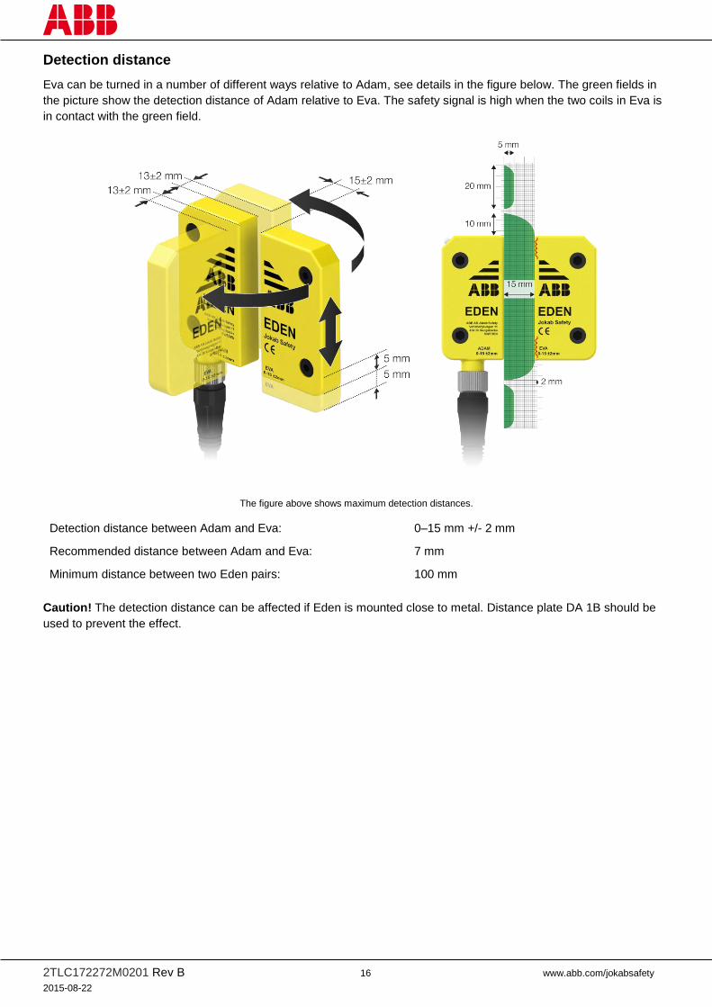
Eva can be turned in a number of different ways relative to Adam, see details in the figure below. The green fields in
the picture show the detection distance of Adam relative to Eva. The safety signal is high when the two coils in Eva is
in contact with the green field.
The figure above shows maximum detection distances.
Detection distance between Adam and Eva:
Recommended distance between Adam and Eva:
Minimum distance between two Eden pairs:
0–15 mm +/- 2 mm
7 mm
100 mm
Caution! The detection distance can be affected if Eden is mounted close to metal. Distance plate DA 1B should be
used to prevent the effect.

2TLC172272M0201 Rev B 17 www.abb.com/jokabsafety
2015-08-22
Mounting
Depending on the cable connector used for the connection to Eden, one or two distance plates might be required for
correct mounting in order to avoid damaging Adam. It is recommended to use the distance plates (DA 1B) supplied
with the Adam models with M12 connector (Adam M12), see figure below. Also, the mounting spacers supplied must
be used in order to physically protect Eden from damage.
The cable should be mounted so that no force is applied on Adam in any directions. The cable should be fixed if it’s
connected to a moving object, for example a cable chain or a door. This can be done with for example two cable
clamps.
Caution! An improperly installed cable can damage the sensor.
Mounting with one distance plate (DA 1B) for Adam M12 using
prewired moulded M12 connector
Mounting with two distance plates (DA 1B) for Adam M12 using M12
connector with glanded cable.
Incorrect mounting without distance plate may cause permanent
damage to the sensor.
Not accepted Accepted

2TLC172272M0201 Rev B 18 www.abb.com/jokabsafety
2015-08-22
Mounting procedure:
1. Fasten each sensor with two M4 screws. Safety screw SM4x20 (2TLA020053R4200) is recommended. The
DA 2B mounting spacer must be used in order to physically protect Eden from damage.
2. Use max tightening torque 0.8 Nm on screws.
3. Lock screw with Loctite or similar if necessary to prevent easy dismounting (refer to risk assessment).
4. Tighten the M12 contact with tightening torque 0.6 Nm. A torque wrench is recommended to ensure a tight
connection and IP69K.
Torque Wrench for M12-connector.
DA 2B

2TLC172272M0201 Rev B 19 www.abb.com/jokabsafety
2015-08-22
Teaching the code
Adam is delivered without code and need to be programmed with the code from an Eva (General or Unique coded).
The code of the first Eva detected by the Adam is automatically programmed as soon as Eva is within the detection
distance. If Adam is programmed to accept an Eva with a general code, it will accept all Eva units with a general code.
If it is programmed to accept an Eva with unique code, it will only accept the unique code of that specific Eva.
Note that it is possible to teach more than one Adam unit to accept the same Eva unit. This is for example applicable
on a sliding door or for machine positioning.
How to program a new Adam without code, to accept a new Eva:
1. Bring the Eva in the range of Adam.
2. Connect the Adam without code to the power supply.
3. The LED on Adam will turn green when the programming procedure is finished.
NB: The programming procedure is taking place only at startup of Adam. Eva must be in range at this time.
NB: If the teaching procedure fails, Adam enters a fail-safe mode and its red LED starts flashing fast. Erase the code,
cycle the power and restart the teaching code procedure.
Caution! The Eva must not be removed during the teaching procedure.
How to erase existing codes from Adam M12-5
1. Remove Eva from Adam’s detection range.
2. Disconnect the power supply on pin 1 on the Adam unit.
3. Connect +24 VDC to pin 2 and 4.
4. Connect the power supply on pin 1 on the Adam unit.
5. After 5-10 s disconnect pin 2 and 4 from +24 VDC.
6. The Adam unit will now be reset and its LED will flash red.
7. Follow normal installation procedure to install Adam again.
NB: If the pin 2 and 4 on the Adam unit is not disconnected from +24 VDC within 5–10 s, Adam enters the fail-safe
mode and the red LED starts flashing fast. It is then necessary to restart the procedure from the beginning.
How to erase existing codes from Adam M12-8
1. Remove Eva from Adam’s detection range.
2. Disconnect the power supply on pin 2 on the Adam unit.
3. Connect +24 VDC to pin 1 and 6.
4. Connect the power supply on pin 2 on the Adam unit.
5. After 5-10 s disconnect pin 1 and 6 from +24 VDC.
6. The Adam unit will now be reset and its LED will flash red.
7. Follow normal installation procedure to install Adam again.
NB: If pin 1 and 6 on the Adam unit are not disconnected from +24 VDC within 5-10 s, Adam enters the fail-safe mode
and the red LED starts flashing fast. It is then necessary to restart the procedure from the beginning.

2TLC172272M0201 Rev B 20 www.abb.com/jokabsafety
2015-08-22
Replacing Eva
When an Eva should be replaced, the used one needs to be deleted from the Adam sensor. To delete Eva from the
internal memory, follow below instructions.
1. Remove Eva out of sensing distance.
2. Disconnect the power supply from Adam (0 V should remain connected)*.
3. Connect +24 VDC to OSSD1 Output and OSSD2 Output.
4. Connect the power supply (+24 VDC) to Adam. The LED will turn red.
5. When the LED turns green after 5–10 s, disconnect the voltage from OSSD1 Output and OSSD2 Output. The
Adam sensor is restored and the LED flashes in red.
6. Disconnect the power supply from Adam.
7. Move Eva within sensor distance and connect the power supply to Adam. The green LED is lighted and the
teaching of Eva’s code into Adam is done.
NB: If OSSD1 Output and OSSD2 output on the Adam are not disconnected from +24 VDC within 5–10 sec, Adam
enters the fail-safe mode and the red LED starts flashing fast. It is then necessary to restart the procedure from the
beginning.
Testing the safety functions
Make sure the safety unit and safety module is working properly by following these steps:
1. Interrupt Eden output by moving Eva away from Adam. The LED will light red when Eva is out of range of
Adam.
2. Interrupt the OSSD safety circuit before the unit to be tested. The LED will flash between green and red.
3. Move Eva to a position next to Adam. The LED will light green if the safety circuit(s) before this unit is not
interrupted.
4. An additional function test can be made by slowly moving Eva away from Adam. The LED will flash fast green
when Eva is 2 mm from the maximum detection distance to Adam.
* Be aware that if the voltage is disconnected at mains and not after the power supply, the charge may keep the
voltage at higher level for a longer period of time. Always check that the voltage level has reached < 1.0 V before
reconnecting it.
2TLC172272M0201 Rev B 21 www.abb.com/jokabsafety
2015-08-22
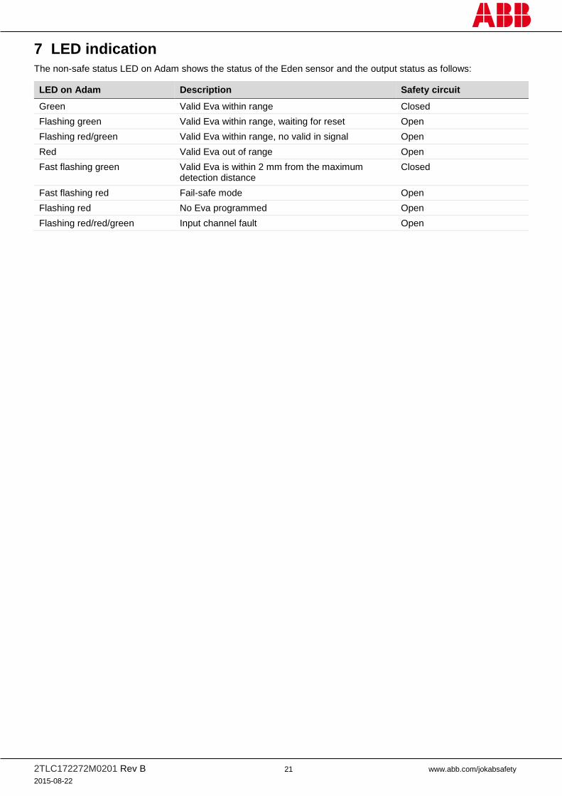
7 LED indication
The non-safe status LED on Adam shows the status of the Eden sensor and the output status as follows:
LED on Adam Description Safety circuit
Green Valid Eva within range Closed
Flashing green Valid Eva within range, waiting for reset Open
Flashing red/green Valid Eva within range, no valid in signal Open
Red Valid Eva out of range Open
Fast flashing green Valid Eva is within 2 mm from the maximum detection distance
Closed
Fast flashing red Fail-safe mode Open
Flashing red No Eva programmed Open
Flashing red/red/green Input channel fault Open
2TLC172272M0201 Rev B 22 www.abb.com/jokabsafety
2015-08-22
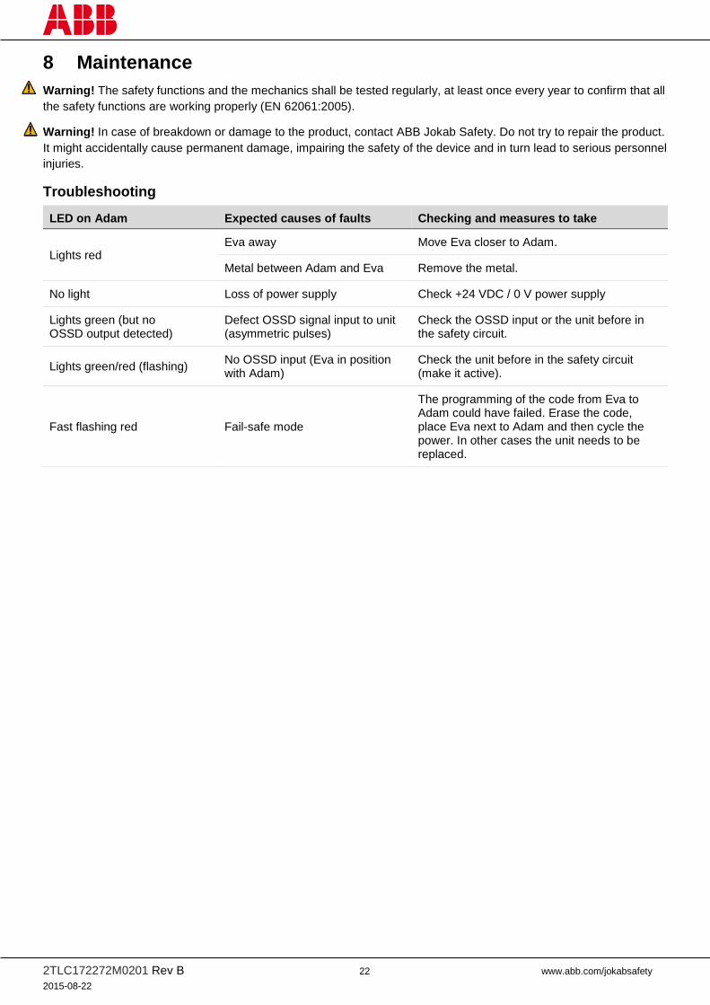
8 Maintenance
Warning! The safety functions and the mechanics shall be tested regularly, at least once every year to confirm that all
the safety functions are working properly (EN 62061:2005).
Warning! In case of breakdown or damage to the product, contact ABB Jokab Safety. Do not try to repair the product.
It might accidentally cause permanent damage, impairing the safety of the device and in turn lead to serious personnel
injuries.
Troubleshooting
LED on Adam Expected causes of faults Checking and measures to take
Lights red Eva away Move Eva closer to Adam.
Metal between Adam and Eva Remove the metal.
No light Loss of power supply Check +24 VDC / 0 V power supply
Lights green (but no OSSD output detected)
Defect OSSD signal input to unit (asymmetric pulses)
Check the OSSD input or the unit before in the safety circuit.
Lights green/red (flashing) No OSSD input (Eva in position with Adam)
Check the unit before in the safety circuit (make it active).
Fast flashing red Fail-safe mode
The programming of the code from Eva to Adam could have failed. Erase the code, place Eva next to Adam and then cycle the power. In other cases the unit needs to be replaced.

2TLC172272M0201 Rev B 23 www.abb.com/jokabsafety
2015-08-22
9 Model overview
Type Article number Description
Adam OSSD-Info M12-5 2TLA020051R5400 Pin 5: Information
Adam OSSD-Info M12-8 2TLA020051R5700 Pin 5 and 8: Information
Adam OSSD-Reset M12-5 2TLA020051R5600 Pin 5: Reset/Indication
Adam OSSD-Reset M12-8 2TLA020051R5900 Pin 5: Reset/Indication, Pin 8: Information
Eva General code 2TLA020046R0800 General code
Eva Unique code 2TLA020046R0900 Unique code
Accessories
Type Article number Description
DA 1 2TLA020053R0000 Distance plate in clear polycarbonate
DA 1B 2TLA020053R0700 Distance plate in yellow PBT
DA 2B 2TLA020053R0300 Mounting spacer
SM4x20 2TLA020053R4200 Safety screw for mounting Adam and Eva
SBITS 2TLA020053R5000 Safety screwdriver bit
Smile 12RG Reset button 2TLA030053R2700 Reset button for Eden with 8 pins
Smile 12RF Reset button 2TLA030053R2600 Reset button for Eden with 5 pins
M12-3G 2TLA020055R0700 Y-connector for serial connection
Torque wrench 2TLA020053R0900 For M12 contact
Safety screws and
screwdriver bit Distance plate (DA 1B)
DA 2B

2TLC172272M0201 Rev B 24 www.abb.com/jokabsafety
2015-08-22
Cables
M12-C312
Type Article number Description
M12-C61 2TLA020056R0000 6 m cable 5 x 0.34 mm2
Shielded cable with straight M12 female connector
M12-C101 2TLA020056R1000 10 m cable 5 x 0.34 mm2
Shielded cable with straight M12 female connector.
M12-C201 2TLA020056R1400 20 m cable 5 x 0.34 mm2
Shielded cable with straight M12 female connector.
M12-C112 2TLA020056R2000 1 m cable 5 x 0.34 mm2
Shielded cable with straight M12 female connector and male connector.
Shielded cable connected to pin 3 (0 V) on male connector.
M12-C312 2TLA020056R2100 3 m cable 5 x 0.34 mm2
Shielded cable with straight M12 female connector and male connector.
Shielded cable connected to pin 3 (0 V) on male connector.
M12-C612 2TLA020056R2200 6 m cable 5 x 0.34 mm2
Shielded cable with straight M12 female connector and male connector.
Shielded cable connected to pin 3 (0 V) on male connector.
M12-C1012 2TLA020056R2300 10 m cable 5 x 0.34 mm2
Shielded cable with straight M12 female connector and male connector.
Shielded cable connected to pin 3 (0 V) on male connector.
M12-C2012 2TLA020056R2400 20 m cable 5 x 0.34 mm2
Shielded cable with straight M12 female connector and male connector.
Shielded cable connected to pin 3 (0 V) on male connector.
M12-C63 2TLA020056R3000 6 m cable 8 x 0.34 mm2
Shielded cable with straight M12 female connector.
M12-C103 2TLA020056R4000 10 m cable 8 x 0.34 mm2
Shielded cable with straight M12 female connector.
M12-C203 2TLA020056R4100 20 m cable 8 x 0.34 mm2
Shielded cable with straight M12 female connector.
M12-C134 2TLA020056R5000 1 m cable 8 x 0.34 mm2
Shielded cable with straight M12 female connector and male connector.
M12-C334 2TLA020056R5100 3 m cable 8 x 0.34 mm2
Shielded cable with straight M12 female connector and male connector.

2TLC172272M0201 Rev B 25 www.abb.com/jokabsafety
2015-08-22
10 Technical data
Manufacturer
Address ABB JOKAB SAFETY
Varlabergsvägen 11
S-434 39 Kungsbacka
Sweden
Power supply
Rated operating voltage +24 VDC +15 % -40 %
Total current consumption 30 mA at +24 VDC
35 mA at 18 VDC
45 mA at 12 VDC
Pin 5 (Information/reset button pin) Max 30 mA (VCC – 4 V)
Pin 8 (Information) Max 15 mA (VCC – 4 V)
OSSD outputs (signal 1 and 2 Out) Max 50 mA per output (VCC – 4 V).
Electrical data
Voltage drop (OSSD. out) 2.5 V at 25 mA at 50 mA
OFF-state current (OSSD. out) < 3 µA
Transponder frequency 4 MHz
Max. switching frequency 1 Hz
Environmental data
EMC EN 60947-5-3:1999+A1:2005
Ambient temperature Storage: -40…+70°C
Operation: -40…+70°C
Humidity range 35 % to 85 % (with no icing or condensation)
Times
Switch-on delay power on 2 s
Response time at activation < 150 ms
Response time at deactivation First unit: < 30 ms
For each added units: < 5 ms
Risk time First unit: < 30 ms
For each added units: < 5 ms
Mechanical data
Protection class IP67/IP69K
Enclosure type rating Type 1
Material Housing: Polybutylene terephthalate (PBT)
Moulding: Epoxy
Connector M12 8-pole male
M12 5-pole male
Size See drawings below
Weight Adam M12: 80 g
Eva: 70 g
Colour Yellow, grey text
Detection distance (Hysteresis 1–2 mm) 0–15 +/- 2 mm
Assured release distance (Sar) 25 mm
Assured operating distance (Sao) 10 mm

2TLC172272M0201 Rev B 26 www.abb.com/jokabsafety
2015-08-22
Safety / Harmonized Standards
Intended use UL Applications according to NFPA 79
EN 61508:2010 SIL3, PFHd: 4,5 x 10⁻⁹
EN 62061:2005 SIL3
EN ISO 13849-1:2008 Category 4, PLe
EN 60947-5-3:1999+A1:2005 PDF-M
EN ISO 14119:2013 Type 4, high level coded (Eva Unique code)
Type 4, low level coded (Eva General code)
Certificates TÜV süd pending, cULus

2TLC172272M0201 Rev B 27 www.abb.com/jokabsafety
2015-08-22
Guideline for chemical resistance
Chemicals Eden OSSD
Hydrocarbons
aliphatic Good
aromatic Good
halogenated
- fully Poor/Fair
- partly Poor
Alcohols Good
Phenols Poor
Ketones Fair/Good
Amines Not tested
Esters Fair/Good
Ethers Good
Acids
inorganic Good
organic Fair
oxidizing Poor
Alkalis Poor
Automotive fluids
Greases (non-reactive organic esters) Very good
Oils (unsaturated aliphatic mixtures) Very good
Waxes (heavy oils) Very good
Petrol Very good
Cooling liquid (glycol) Very good
Brake fluid (heavy alcohol) Good
Detergents, cleaners Good
Water
hot (> 80°C) Poor
Environmental
UV Good
Very good
-Found unaffected in its performance with regard to time, temperature and stress.
Good
- Found acceptable in normal exposure.
- Long term exposure may result in minor loss of properties.
- Higher temperatures may result in major loss of properties.
Fair
- Only for short exposures at lower temperatures or when loss of mechanical properties is not critical.
Poor
- Will result in failure or severe degradation.

2TLC172272M0201 Rev B 28 www.abb.com/jokabsafety
2015-08-22
Eden dimensions
NB: All dimensions in millimetres.
CAD model
For CAD models please visit www.abb.com/jokabsafety
Adam M12, 5 pole
female. Contact
seen from cable
side.
Adam M12, 8 pole
female. Contact seen
from cable side.

2TLC172272M0201 Rev B 29 www.abb.com/jokabsafety
2015-08-22
11 EC Declaration of conformity