Embed Size (px)
Citation preview
Code of Practice for
Foundations 2017
FOREWORD
The Buildings Department established the Technical Committee (TC) on the Code of Practice for Foundations for the purpose of collecting views and feedbacks on the use of the Code of Practice for Foundations published in 2004 (the 2004 Code) from the building industry and with a view to keeping the Code of Practice in pace with the advancement in design, analysis and construction practice.
This Code, Code of Practice for Foundations 2017 (the 2017 Code) is issued upon completion of the review by the TC, which has focused on four fronts: (a) the advancement in design and analysis; (b) the experience gained and the views and feedbacks received on the use of the 2004 Code; (c) the commonly adopted local practice on foundation construction; and (d) necessary updates consequent upon the publication of the relevant Codes of Practice, and the issue of relevant Practice Notes for Authorized Persons, Registered Structural Engineers and Registered Geotechnical Engineers.
The contributions and efforts given by the invited members of the TC in the preparation of the 2017 Code are greatly appreciated.
The 2017 Code will be reviewed regularly. The Buildings Department welcomes suggestions for improving the Code.
This Code of Practice is available for viewing in the Buildings Department website at http://www.bd.gov.hk. The document may be downloaded subject to terms and conditions stipulated in the website.
First Issue : April 2017
i
Contents
Page No. 1. General...............................................................................................................................1
1.1 Scope.......................................................................................................................1 1.2 Glossary...................................................................................................................1 1.3 Abbreviations ..........................................................................................................4 1.4 Symbols...................................................................................................................5
2. General Design Requirements .........................................................................................8
2.1 General ....................................................................................................................8 2.1.1 Basic Requirements ..................................................................................8 2.1.2 Compatibility of Design and Construction ...............................................8 2.1.3 Classification of Soils and Rocks .............................................................8
2.2 Allowable Bearing Pressure, Bond or Friction of Ground......................................9 2.2.1 Rational Design Method ...........................................................................9 2.2.2 Presumed Values.......................................................................................9 2.2.3 In Situ Testing Method ...........................................................................14 2.2.4 Bearing Capacity Equation Method........................................................14 2.2.5 Other Methods ........................................................................................19
2.3 Foundation Settlement and Rotation.....................................................................19 2.3.1 Estimation of Settlement.........................................................................19 2.3.2 Acceptable Settlement and Rotation.......................................................23
2.4 Structures on Reclaimed Land ..............................................................................24 2.4.1 General Design Rules .............................................................................25 2.4.2 Alternative Approach..............................................................................25 2.4.3 Long-term Monitoring and/or Maintenance............................................26 2.4.4 Reclaimed Land with Consolidation Substantially Completed .............26
2.5 Structural Requirements........................................................................................26 2.5.1 General ....................................................................................................26 2.5.2 Design Loads...........................................................................................26 2.5.3 Underground Water ................................................................................27 2.5.4 Resistance to Sliding, Uplift and Overturning........................................28 2.5.5 Materials and Stresses.............................................................................29
2.6 Corrosion Protection of Foundations ....................................................................31 2.6.1 General ....................................................................................................31 2.6.2 Concrete Foundations .............................................................................31 2.6.3 Steel Piles................................................................................................31 2.6.4 Marine Foundations ................................................................................31
2.7 Foundation Plans...................................................................................................32 2.8 Foundation Design in Scheduled Areas ................................................................34
2.8.1 General ....................................................................................................34 2.8.2 Foundation Design in Scheduled Area Nos. 2 and 4 ..............................34
2.8.2.1 General………………………………………………………… 34 2.8.2.2 Marble Rock Mass Classification……………………………... 35 2.8.2.3 Foundations Bearing on Soil in Scheduled Area Nos. 2 and 4…37
ii
2.8.2.4 Foundations Bearing on Marble Bedrock………………………38 2.9 Foundation Design in Designated Area ................................................................39 2.10 Foundation Design in Sloping Ground .................................................................40
3. Site Investigation.............................................................................................................41
3.1 General ..................................................................................................................41 3.2 Documentary Studies ............................................................................................41 3.3 Site Survey ............................................................................................................41 3.4 Ground Investigation.............................................................................................43
3.4.1 General ....................................................................................................43 3.4.2 Supervision for Ground Investigation Works .........................................44 3.4.3 Preparation of Ground Investigation Reports .........................................44 3.4.4 Soil and Rock Sampling .........................................................................44 3.4.5 Number and Disposition of Boreholes/Trial Pits....................................44 3.4.6 Depth of Ground Investigation ...............................................................45 3.4.7 Groundwater ...........................................................................................45
3.5 Ground Investigation in Scheduled Areas.............................................................46 3.6 Ground Investigation within Designated Area......................................................46
4. Shallow Foundations ......................................................................................................47
4.1 General Requirements...........................................................................................47 4.2 Allowable Bearing Pressure and Settlement .........................................................47
4.2.1 Shallow Foundations on Categories 1(a), 1(b), 1(c), 1(d) or 2 Rock......47 4.2.2 Shallow Foundations on Soil ..................................................................47
4.3 Structural Requirements........................................................................................49 4.4 Common Types of Shallow Foundations ..............................................................49
4.4.1 Pad Footings............................................................................................49 4.4.2 Strip Footings..........................................................................................49 4.4.3 Raft Foundations.....................................................................................50
5. Pile Foundations..............................................................................................................51
5.1 General ..................................................................................................................51 5.1.1 Recognized Types of Pile Foundations...................................................51 5.1.2 Group Effect............................................................................................51 5.1.3 Minimum Pile Spacing ...........................................................................52 5.1.4 Horizontal Restraints to Piles and Pile Caps ..........................................52 5.1.5 Piles Providing Resistance against Sliding .............................................52 5.1.6 Piles Providing Resistance against Uplift, Overturning and Buoyancy..53 5.1.7 Pile Group Settlement .............................................................................53
5.2 Negative Skin Friction ..........................................................................................53 5.2.1 Design Requirement................................................................................53 5.2.2 Conventional Approach ..........................................................................54 5.2.3 Alternative Approach..............................................................................55
5.3 Load Capacity of Piles ..........................................................................................55 5.3.1 Structural Strength ..................................................................................55 5.3.2 Ground Resistance for Piles in Compression..........................................56
iii
5.3.3 Ground Resistance for Piles Subjected to Uplift Forces.........................58 5.3.4 Ground Resistance for Piles Subjected to Lateral Load..........................64
5.4 Common Pile Types..............................................................................................66 5.4.1 Steel H-Piles/Steel Tubular Piles ............................................................66 5.4.2 Socketed Steel H-Piles............................................................................67 5.4.3 Precast Reinforced Concrete Piles ..........................................................67 5.4.4 Precast Prestressed Spun Concrete Piles.................................................68 5.4.5 Driven Cast-in-Place Concrete Piles.......................................................68 5.4.6 Small Diameter Bored Piles....................................................................68 5.4.7 Large Diameter Bored Piles ....................................................................70 5.4.8 Mini-Piles................................................................................................71 5.4.9 Barrettes ..................................................................................................73 5.4.10 Hand-Dug Caissons ................................................................................73 5.4.11 Steel H-Piles Driven to Bedrock.............................................................73 5.4.12 Steel H Shear Piles..................................................................................76
5.5 Pile Caps ...............................................................................................................76
6. Other Foundation Types/Elements ...............................................................................78
6.1 Basements and Hollow Boxes...............................................................................78 6.2 Diaphragm Walls ..................................................................................................78 6.3 Retaining Walls.....................................................................................................79 6.4 Ground Anchors ....................................................................................................80 6.5 Re-use of Existing Foundations ............................................................................80
6.5.1 General ....................................................................................................80 6.5.2 General Requirements on Testing...........................................................81 6.5.3 Large Size Concrete Piles .......................................................................81 6.5.4 Small Size Concrete Piles.. ................................................................. .. 81 6.5.5 Steel Piles and Mini-Piles .......................................................................82 6.5.6 Concrete Footings ...................................................................................82
7. Construction Practice and Site Safety for Foundation Works ...................................83
7.1 General ..................................................................................................................83 7.1.1 General Requirements.............................................................................83 7.1.2 Quality Supervision for Foundation Works ............................................83 7.1.3 Construction Materials............................................................................83 7.1.4 Excavation ..............................................................................................84
7.2 Effect of Foundation Works on Adjacent Structures and Land ............................84 7.2.1 Assessment of the Effect of Foundation Works .....................................84 7.2.2 Shoring and Underpinning......................................................................85 7.2.3 Monitoring Plan ......................................................................................85 7.2.4 Ground Settlement ..................................................................................85 7.2.5 Dewatering..............................................................................................86 7.2.6 Vibration .................................................................................................86 7.2.7 Public Relations Plan for Piling Works ..................................................88 7.2.8 Blasting ...................................................................................................89
7.3 Foundation Records and Reports ..........................................................................89 7.4 Pile Construction...................................................................................................90
iv
7.4.1 Driving Test and Trial Piles....................................................................90 7.4.2 Test Boring..............................................................................................90 7.4.3 Pre-Drilling .............................................................................................91 7.4.4 Post Construction Proof Drilling ............................................................91 7.4.5 Proof Tests ..............................................................................................92 7.4.6 Further on Site Tests ...............................................................................92
7.5 Construction Tolerances........................................................................................92 7.6 Ground Treatment .................................................................................................93 7.7 Control of Nuisance ..............................................................................................93 7.8 Foundation Works in Scheduled Areas.................................................................94
7.8.1 General ....................................................................................................94 7.8.2 Performance Review and Settlement Monitoring for Scheduled Area
Nos. 2 and 4 ............................................................................................94
8. Testing of Foundations and Ground .............................................................................95
8.1 General ..................................................................................................................95 8.2 Plate Load Test......................................................................................................95 8.3 Standard Penetration Test .....................................................................................97 8.4 Compression Loading Test ...................................................................................97 8.5 Core-Drilling Test .................................................................................................98 8.6 Sonic Logging .......................................................................................................99 8.7 Sonic Echo Test ....................................................................................................99 8.8 Vibration Test .....................................................................................................100 8.9 Dynamic Load Test for Driven Piles...................................................................100 8.10 Tension Loading Test..........................................................................................101 8.11 Lateral Load Test ................................................................................................102 8.12 Ultrasonic Echo Sounder Test.............................................................................104
≈≈≈≈≈≈≈≈≈≈≈≈≈≈≈≈
v
List of Tables
Table 2.1 Presumed Allowable Vertical Bearing Pressure under Foundations on Horizontal Ground/Bedrock……………………………………..... 11
Table 2.2 Presumed Allowable Bond or Friction Between Rock and Concrete or Grout for Piles…………………………………………………………. 13
Table 2.3 Bearing Capacity Factors for Computing Ultimate Bearing Capacity of Shallow Foundations…………………………………………………… 17
Table 2.4 Poisson’s Ratio of Soil……………………………………………….... 23 Table 2.5 Classification of Marble Rock Mass…………………………………... 35 Table 2.6 Drill Hole Rating……………………………………………………..... 37 Table 2.7 Site Classification……………………………………………………... 38 Table 2.8 Limits on Increase of Vertical Effective Stress at Marble Surface…..... 38 Table 2.9 Reference Value for Redundancy Factor…………………………….... 39 Table 5.1 Correlation of Constant of Horizontal Subgrade Reaction with SPT N-
values for Granular Soil……………………………………………….. 65 Table 5.2 Reduction Factor for Constant of Horizontal Subgrade Reaction for
Laterally Loaded Pile Group…………………………………..………. 65 Table 7.1 Example of the Contingency Measures for Three Triggering Levels…. 85 Table 7.2 Typical Values for the Three Triggering Levels on Nearby Buildings,
Structures or Services that are not Sensitive to Settlement……………. 86 Table 7.3 Limits of ppv for Protection of Buildings……………………….…….. 87 Table 7.4 Construction Tolerances…..…………………………………..………. 92 Table 8.1 Standard Loading Procedures for Lateral Load Test…………………... 103
List of Figures
Figure 2.1 Definition of Total Core Recovery of the Designated Grade………..... 13 Figure 2.2 Generalised Loading and Geometric Parameters for Shallow
Foundations………………………………………………………..…… 16 Figure 2.3 Linear Interpolation Procedures for Determining Ultimate Bearing
Capacity of a Spread Shallow Foundation near the Crest of a Slope.…. 18 Figure 2.4 Shallow Foundation of Irregular Shape………………………………… 19 Figure 2.5 Definition of Compressibility Parameters..…………………………….. 22 Figure 2.6 Definition of Marble Quality Designation……………………………. 36 Figure 4.1 Flow Chart of Procedures for Design of Shallow Foundations……...... 48 Figure 5.1 Configuration of Rock Cone/Soil Column for Rock Socketed Piles….. 61 Figure 5.2 Configuration of Soil Cone/Soil Column for Group of Closely-spaced
Friction Piles in Soil…………………………………………………... 64
vi
1. GENERAL
1.1 SCOPE
This Code of Practice was prepared on the basis of being ‘deemed-to-satisfy’ the Building (Construction) Regulations as far as the design and construction of foundations are concerned. Departure from the requirements and recommendations of this Code of Practice or the use of other standards or codes of practice for design of foundations may require demonstration of the compliance with the provisions of the Building (Construction) Regulations.
This Code of Practice is intended for local use only. Methods of foundation design that are currently and commonly used in Hong Kong are included in this Code of Practice as far as possible. It should be noted that some methods of foundation design have been developed from practical considerations and experience and have been accepted on the basis that they have been demonstrated to have worked satisfactorily.
In addition to technical aspects, this Code of Practice also includes brief descriptions of local practices that could affect the design and construction of foundations. The descriptions cover mainly the purposes and objectives of the practices. Detailed procedural requirements are not included; reference should be made to the most current practice notes issued by the Buildings Department or other government departments or bureaux.
Design for seismic effect is not presently included in this Code of Practice. However, where seismic effect is considered in the design of the superstructure, it should also be considered in the design of the foundation.
1.2 GLOSSARY
For the purpose of this Code of Practice the following glossary of terms applies:
Allowable bearing pressure. The maximum allowable bearing pressure that may be applied at the base of the foundation, taking into account the ultimate bearing capacity of the soil or rock, the magnitude and type of settlement expected and the ability of the structure to accommodate such settlement. [NOTE : The allowable bearing pressure is a combined function of the site conditions, including all construction in the vicinity, and the characteristics of the proposed foundation/structure.]
Allowable load. The maximum load that may be applied safely to a foundation after taking into account its ultimate bearing capacity, negative skin friction, pile spacing, overall bearing capacity of the ground below the foundation and allowable settlement.
Authorized Person. A person whose name is on the authorized persons’ register kept under section 3(1) of the Buildings Ordinance.
1
Bell-out. An enlargement of the base area of a pile, formed in situ by undercutting (under-reaming) the soil or rock at the base of a bored pile.
Designated Area. The Designated Area of Northshore Lantau as described in the GEO Technical Guidance Note No. 12 published by Geotechnical Engineering Office or PNAP APP-134.
Dry condition. For shallow foundations, dry condition means that the highest anticipated groundwater level is at a depth of not less than 1m or the width of the shallow foundation, whichever is the greater, below the base of the foundation. The width of the shallow foundation shall be the lesser dimension of a rectangular shallow foundation or the largest inscribed rectangle of an irregular shallow foundation (see Figure 2.4), or the diameter of a circular shallow foundation.
Final set. The penetration per blow of hammer at the founding level of a driven pile.
Foundation. That part of a building, building works, structure or street in direct contact with and transmitting loads to the ground.
Ground investigation. Any exploratory drilling, boring, excavating and probing of land for obtaining any information on ground conditions and includes the installation of instruments, sampling, field testing, any other site operation and laboratory testing of samples obtained from such operations.
Ground investigation field works. All site operations in ground investigation and exclude laboratory testing of samples and field density tests.
Highest anticipated groundwater level. (see definition given in clause 2.5.3)
Highest possible groundwater level. (see definition given in clause 2.5.3)
Meta-sedimentary rock. A sedimentary rock that shows evidence of having been subjected to metamorphism that differs from the conditions under which the sedimentary rock originated.
Negative skin friction. The downdrag skin friction resulted from the consolidation of compressible soil strata.
Permanent tension. Tension in a foundation element induced by a loading effect of permanent nature, such as soil loads and uplift due to groundwater, acting continuously throughout its service life.
Pile cap. A concrete structure built on the head of a pile or a group of piles for transmission of loads from the structure above to the pile or group of piles.
Pile spacing. The distance measured from centre to centre of adjacent piles.
2
Pre-boring. Removal of ground or underground obstacles by boring or other means prior to the installation of pile foundation. This operation shall be carried out for one of the following purposes: installation of socketed steel H-piles and mini-piles, removal of or penetration through underground obstructions for driven steel H-piles, or mitigation of the effect of vibration for driven steel H-piles (see clause 7.2.6).
Proof test. Test to be carried out on representative foundation units to ascertain the performance of foundation under load as required by regulation 30 of the Building (Construction) Regulations.
Qualified land surveyor. A person whose name is on the professional land surveyors’ register kept under section 11 of the Surveyors Registration Ordinance or the authorized land surveyors’ register kept under section 11 of the Land Survey Ordinance.
Raking pile. A pile installed at an inclination to the vertical.
Registered Geotechnical Engineer. A person whose name is on the geotechnical engineers’ register kept under section 3(3A) of the Buildings Ordinance.
Registered Specialist Contractor (Foundation Works). A contractor whose name is on the sub-register of the foundation works category in the register of specialist contractors maintained under section 8A of the Buildings Ordinance.
Registered Specialist Contractor (Ground Investigation Field Works). A contractor whose name is on the sub-register of the ground investigation field works category in the register of specialist contractors maintained under section 8A of the Buildings Ordinance.
Registered Structural Engineer. A person whose name is on the structural engineers’ register kept under section 3(3) of the Buildings Ordinance.
Rock socket. The penetration formed in rock for embedding a portion of a pile.
Rock socketed pile or Socketed pile. A pile with the toe portion embedded into a rock socket to derive load resistance through bearing, bond or friction with the rock.
Skin friction. The frictional resistance developed at the interface between a foundation member and the surrounding ground.
Site investigation. An investigation of the physical characteristics of the site and includes documentary studies, site survey and ground investigation.
SPT N-value. The uncorrected N-value obtained from standard penetration test.
Submerged condition. For shallow foundations, submerged condition means that the design groundwater level is at or above the base of the foundation.
3
Test driving/installation. Test driving or installation of one or more piles carried out to verify the design and/or other installation method.
Test pile. A pile to which a test is applied.
Transient tension. Tension induced to the foundation that is not categorised as permanent tension, such as wind load and load combination with wind.
Trial pile. A pile tested for the purpose of verifying the design of the piles, including the design parameters and the load carrying capacity, and such verification usually requires loading test.
Ultimate bearing capacity. The value of the loading intensity for a particular foundation at which the resistance of the bearing stratum becomes fully mobilized or undergoes substantial deformation.
Working load. The service load which the foundation is designed to carry.
1.3 ABBREVIATIONS
For the purpose of this Code of Practice the following abbreviations apply:
AP Authorized Person CS1 Construction Standard 1 CS2 Construction Standard 2 ETWB Environmental, Transport and Works Bureau (a former government
bureau) GEO Geotechnical Engineering Office GEOGUIDE 2 “Guide to Site Investigation” published by GEO GEOGUIDE 3 “Guide to Rock and Soil Descriptions” published by GEO HOKLAS Hong Kong Laboratory Accreditation Scheme MQD Marble Quality Designation NSF Negative Skin Friction PNAP Practice Note for Authorized Persons, Registered Structural
Engineers and Registered Geotechnical Engineers PR Plan Public Relations Plan RSE Registered Structural Engineer RGE Registered Geotechnical Engineer RSC Registered Specialist Contractor RQD Rock Quality Designation SPT Standard Penetration Test TCR Total Core Recovery UCS Uniaxial Compressive Strength
4
1.4 SYMBOLS
For the purpose of this Code of Practice the following symbols apply:
σ' = effective vertical overburden pressure σv' = mean vertical effective stress (kPa) β = shaft resistance coefficient γ = bulk unit weight of the soil γ' = submerged unit weight of the soil γs' = effective unit weight of the soil γw = unit weight of water nh = constant of horizontal subgrade reaction ζcs, ζγs, ζqs = influence factors for shape of foundation ζci, ζγi, ζqi = influence factors for inclination of load ζcg, ζγg, ζqg = influence factors for ground surface ζct, ζγt, ζqt = influence factors for tilting of foundation base af = inclination of the base of the footing φ′ = effective angle of shearing resistance τs = ultimate shaft friction under transient tension µ = friction factor ω = sloping inclination in front of the footing ν = Poisson’s ratio A = cross-section area of the pile B = width or diameter of test plate Bf = least dimension of footing Bf' = Bf – 2eB c' = effective cohesion of soil cc = temporary compression of the hammer cushion cp = temporary compression of pile cq = temporary compression of ground at pile toe dl = elemental length of the pile D = least lateral dimension of the pile Df = depth from ground surface to the base of shallow foundation Dmin = minimum dead load e = coefficient of restitution eB = eccentricity of load along B direction eL = eccentricity of load along L direction E = Young's modulus of the material of the pile Eh = efficiency of hammer Es = Young's modulus of soil fcu = characteristic strength of concrete fy = characteristic strength of steel Gk = characteristic dead load h = hammer drop height H = horizontal applied load Ia = adverse imposed load including live and soil loads kp = ground borne vibration coefficient
5
l = depth of the consolidation strata L = length of the pile in mm (For piles with rock sockets, L should
be measured to the centre of the rock socket. For piles without rock sockets, L may generally be measured to the pile toe.)
Lf = longer dimension of footing Lf ' = Lf – 2eL
N = SPT N-value Nav = average SPT N-value along pile shaft but not exceeding 40 Nc, Nγ, Nq = general bearing capacity factors which determine the capacity
of a long strip footing acting on the surface of a soil in a homogenous half-space
Nq’ = bearing capacity factor which determines the capacity of replacement piles embedded in granular soil
NSF = negative skin friction p = perimeter of the pile, or perimeter of the circumscribed
rectangle in the case of H-pile P = vertical applied load Pc = allowable ground-bearing capacity of the piles without wind Pcw = allowable ground-bearing capacity of the piles with wind Pn = design pile capacity under working load without wind Pnw = design pile capacity under working load with wind Ps = structural strength of the pile without wind Psw = structural strength of the pile with wind Pu = ultimate capacity of pile q = overburden pressure at base level of the foundation in the
ground adjacent to the foundation (see Figure 2.2(a) for sloping ground)
qa = allowable vertical bearing pressure qb = allowable bearing capacity of replacement piles embedded in
granular soil qo = effective overburden pressure at the base of the foundation, i.e.
qo = γs ' Df , whereγs ' and Df are respectively the effective unit weight and depth of the soil that originally exists above the base of the foundation
qu = ultimate bearing capacity of the granular soil qub = ultimate end bearing resistance of large diameter bored
piles/barrette piles Qk = characteristic imposed load Qu = ultimate resistance against bearing capacity failure r = slope distance of recipient from pile toe (see clause 7.2.6) Ra = allowable anchorage resistance of the pile (see clause 5.3.3) Rbc = allowable bearing capacity for small diameter bored pile (see
clause 5.4.6) Ru = ultimate anchorage resistance of the pile (see clauses 5.1.6 and
5.3.3) s = permanent set of pile. S = settlement measured at test load W during loading test Smax = maximum settlement measured in loading test
6
Ua = uplift due to the highest anticipated groundwater table Up = uplift due to the highest possible groundwater table vres = resultant ppv due to pile driving W = design pile capacity under working load without wind in kN W1 ' = effective weight of rock or soil cone W2 ' = effective weight of soil column above rock or soil cone We = nominal hammer energy Wh = weight of hammer Wk = adverse wind load Wp = weight of pile Wp' = effective self weight of the pile Wr = weight of pile helmet Wt = test load for plate load test (see clause 8.2(2)(b)) x = distance of recipient from pile measured along the ground surface y = depth of pile toe at the time of assessing vres
7
2. GENERAL DESIGN REQUIREMENTS
2.1 GENERAL
2.1.1 BASIC REQUIREMENTS
Foundations of any building or structure shall be designed and constructed to withstand safely all the dead, imposed and wind loads without impairing the stability or inducing excessive movement to the building or of any other building, street, land, slope or services.
The allowable capacity of the soil/rock under working loads where any foundation is founded shall be the lesser of:
(a) the ultimate capacity for bearing, bond or friction with an adequate factor of safety against failure; or
(b) the value in relation to bearing, bond or friction such that the maximum deformation or movement induced to the foundation under working loads can be tolerated by the building, any other building, structure, land, street and services.
The allowable capacity may be increased by 25% when such increase is solely due to wind effects.
In determining the said factor of safety against failure, due consideration shall be given to the form and depth of the foundation, loading characteristics, the general geological conditions of the ground and its surrounding including the presence of dissolution features, jointing conditions and any other relevant characteristics for rock.
2.1.2 COMPATIBILITY OF DESIGN AND CONSTRUCTION
In choosing the method for the determination of the ultimate capacity or for the estimation of settlement, care must be taken to ensure that the site investigation, testing, derivation of parameters, computations, method of construction and standards of acceptance are mutually compatible and consistent with such method.
2.1.3 CLASSIFICATION OF SOILS AND ROCKS
The classification of soils and rocks used in this Code is set out in Table 2.1. Further definition and description can be obtained from GEOGUIDE 3.
8
2.2 ALLOWABLE BEARING PRESSURE, BOND OR FRICTION OF GROUND
The allowable bearing pressure, bond or friction of soils and rocks should be determined by one of the methods given in clauses 2.2.1 to 2.2.5.
2.2.1 RATIONAL DESIGN METHOD
Rational design method for calculating the ultimate capacity should be based on sound engineering approach and should include:
(a) the reasonable interpretation of the results of site investigation;
(b) the assessment of test results obtained in situ or from samples in the laboratory; and
(c) an analysis based on the laws of physics and recognized engineering principles taking into account the ground conditions and foundation geometry, or an established empirical method proven with adequate correlation.
Normally, the allowable capacity is estimated by applying a factor of safety of 3 to the calculated ultimate bearing capacity. However, other factors of safety may be adopted having regard to the nature of the soil or rock, its variability over the site and the reliability of the design method.
2.2.2 PRESUMED VALUES
(1) General
In lieu of a rational design method, the allowable capacity for soils and rocks may also be taken as those presumed values derived from empirical correlation and as stipulated below provided that the following conditions are complied with:
(a) the planning, conducting and supervision of the ground investigation and the interpretation of the results are carried out in accordance with the recommendations given in Chapter 3; and
(b) the structures are not unduly sensitive to settlement or other displacement or movement that may be required to mobilize the allowable capacity.
The presumed values for rock are based on the assumption that slip of the rock will not occur. Therefore, where the rock profile is inclined at such an angle that the bearing capacity of the rock mass may be affected, the rock joints should be checked to ensure that there is no unfavourable joint orientation that could permit slip of the rock to occur.
(2) Allowable Vertical Bearing Values
The allowable vertical bearing pressure for foundations on horizontal ground may be estimated from Table 2.1 on the basis of the material description.
9
(3) Allowable Lateral Bearing Pressure for Rock
The allowable lateral bearing pressure for rock may be taken as one third of the allowable vertical bearing pressure provided that no adverse rock joints exist.
(4) Allowable Bond or Friction between Rock and Concrete
The allowable bond or friction between rock and concrete for piles may be estimated from Table 2.2.
(5) Footings of Minor Temporary Structures
A presumed allowable vertical bearing pressure of 100 kPa (if dry) or 50 kPa (if submerged) may be used for the design of footings on horizontal ground of minor temporary structures such as fencing and hoarding.
10
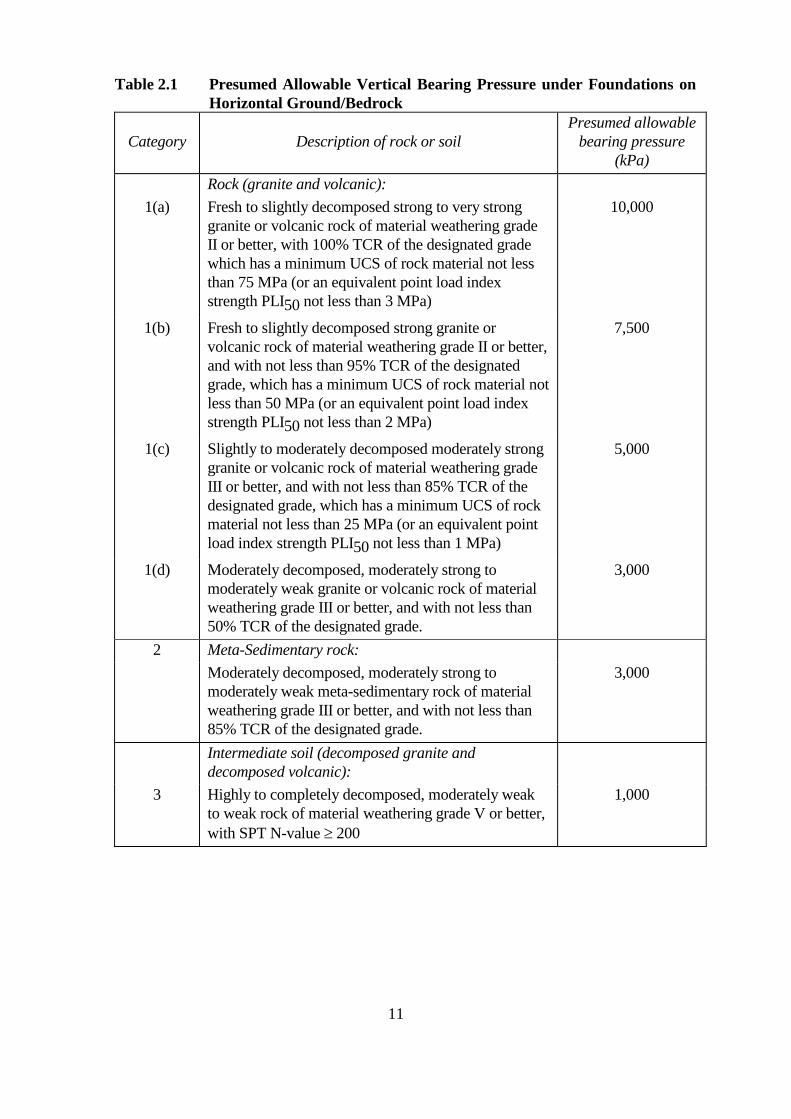
Table 2.1 Presumed Allowable Vertical Bearing Pressure under Foundations on Horizontal Ground/Bedrock
Category Description of rock or soil Presumed allowable
bearing pressure (kPa)
Rock (granite and volcanic): 1(a) Fresh to slightly decomposed strong to very strong
granite or volcanic rock of material weathering grade II or better, with 100% TCR of the designated grade which has a minimum UCS of rock material not less than 75 MPa (or an equivalent point load index strength PLI50 not less than 3 MPa)
10,000
1(b) Fresh to slightly decomposed strong granite or volcanic rock of material weathering grade II or better, and with not less than 95% TCR of the designated grade, which has a minimum UCS of rock material not less than 50 MPa (or an equivalent point load index strength PLI50 not less than 2 MPa)
7,500
1(c) Slightly to moderately decomposed moderately strong granite or volcanic rock of material weathering grade III or better, and with not less than 85% TCR of the designated grade, which has a minimum UCS of rock material not less than 25 MPa (or an equivalent point load index strength PLI50 not less than 1 MPa)
5,000
1(d) Moderately decomposed, moderately strong to moderately weak granite or volcanic rock of material weathering grade III or better, and with not less than 50% TCR of the designated grade.
3,000
2 Meta-Sedimentary rock: Moderately decomposed, moderately strong to moderately weak meta-sedimentary rock of material weathering grade III or better, and with not less than 85% TCR of the designated grade.
3,000
3
Intermediate soil (decomposed granite and decomposed volcanic): Highly to completely decomposed, moderately weak to weak rock of material weathering grade V or better, with SPT N-value ≥ 200
1,000
11

Table 2.1 Presumed Allowable Vertical Bearing Pressure under Foundations on Horizontal Ground/Bedrock (Continued)
Category Description of rock or soil Presumed allowable
bearing pressure (kPa)
Non-cohesive soil (sands and gravels): Dry Submerged 4(a) Very dense – SPT N-value >50 500 250 4(b) Dense – SPT N-value 30-50; requires pick for
excavation; 50 mm peg hard to drive 300 150
4(c) Medium dense – SPT N-value 10-30 100 50 4(d) Loose – SPT N-value 4-10, can be excavated with
spade; 50 mm peg easily driven <100 <50
Cohesive soil (clays and silts): 5(a) Very stiff or hard – Undrained shear strength >150
kPa; can be indented by thumbnail 300
5(b) Stiff – Undrained shear strength 75-150 kPa; can be indented by thumb
150
5(c) Firm – Undrained shear strength 40-75 kPa; can be moulded by strong finger pressure
80
Notes:
(1) The presumed values for allowable bearing pressure given are for foundations with negligible lateral loads at bearing level.
(2) The self weight of the length of pile embedded in soil or rock does not need to be included into the calculation of bearing stresses.
(3) Minimum socket depth along the pile perimeter is 500 mm for categories 1(a) and 1(b), and 300 mm for categories 1(c), 1(d) and 2.
(4) TCR of the designated grade is defined in Figure 2.1.
(5) The TCR of the designated grade should be proved to a depth at least 5 m into the specified category of rock. This requirement is deemed to be complied with if the rock underneath the minimum socket depth as mentioned in note (3) above has a length of at least 5 m which can be divided into a number of segments (in consecutive manner) such that (a) each segment is 1 m; and (b) the calculated TCR in accordance with Figure 2.1 of each segment should satisfy the required percentage of TCR of the designated grade.
(6) The bearing surface of rock on which the foundation will be rested should be of the designated category and in an intact condition for a depth not less than 600 mm.
(7) Weathering grades are defined in GEOGUIDE 3.
12
(8) The point load index strength of rock quoted in the table is the equivalent value for 50 mm diameter cores.
(9) The definition of Dry Condition and Submerged Condition are given in clause 1.2.
(10) Where the ground is intermediate between dry and submerged, the presumed value may be obtained by linear interpolation.
(11) The use of presumptive values does not preclude the requirement for consideration of settlement of the structure.
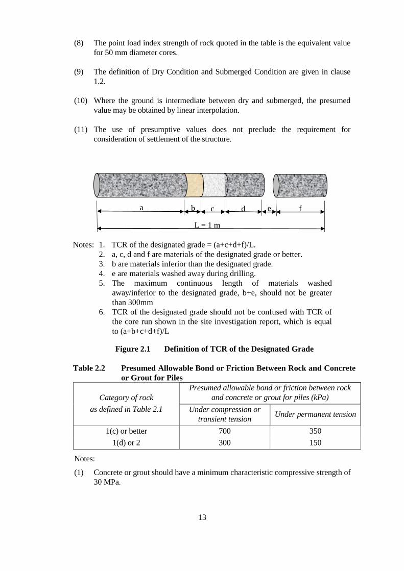
L = 1 m
a b c d e f
Notes: 1. TCR of the designated grade = (a+c+d+f)/L. 2. a, c, d and f are materials of the designated grade or better. 3. b are materials inferior than the designated grade. 4. e are materials washed away during drilling. 5. The maximum continuous length of materials washed
away/inferior to the designated grade, b+e, should not be greater than 300mm
6. TCR of the designated grade should not be confused with TCR of the core run shown in the site investigation report, which is equal to (a+b+c+d+f)/L
Figure 2.1 Definition of TCR of the Designated Grade
Table 2.2 Presumed Allowable Bond or Friction Between Rock and Concrete or Grout for Piles
Category of rock Presumed allowable bond or friction between rock
and concrete or grout for piles (kPa) as defined in Table 2.1 Under compression or
transient tension Under permanent tension
1(c) or better 1(d) or 2
700 300
350 150
Notes:
(1) Concrete or grout should have a minimum characteristic compressive strength of 30 MPa.
13
(2) The presumed value of transient tension is for design for transient load such as wind load.
2.2.3 IN SITU TESTING METHOD
The allowable capacity for soils and rocks may also be estimated by appropriate load testing of the foundation on site. The following should be considered when using this method:
(a) the variation at founding conditions between the location of the testing foundation and locations of the actual foundations;
(b) the duration of load application in the test as compared to the working life of the foundation; and
(c) the scale effect of the test relative to the full size of the foundation.
2.2.4 BEARING CAPACITY EQUATION METHOD
Allowable Vertical Bearing Pressure of Shallow Foundation founded on Soil
The allowable vertical bearing pressure of foundations founded on soils derived by bearing capacity equation may be taken as:
qu − qoq = + qa F o
where qa = allowable vertical bearing pressure qu = ultimate bearing capacity of the granular soil, which should be limited
to 3,000kPa qo = effective overburden pressure at the base of the foundation, i.e. qo = γs'
Df , whereγs' and Df are respectively the effective unit weight and depth of the soil that originally exists above the base of the foundation
F = factor of safety not less than 3
The ultimate bearing capacity of the soil for shallow foundation may be estimated by the following equation:
Qu ' qu = = c Nc ζcs ζci ζct ζcg + 0.5 Bf ' γs ' Nγζγs ζγi ζγt ζγg + q Nq ζqs ζqi ζqtBf 'Lf '
where Nc, Nγ, Nq = general bearing capacity factors which determine the capacity of a long strip footing
Qu = ultimate resistance against bearing capacity failure c' = effective cohesion of soil γs' = effective unit weight of soil q = overburden pressure in the ground adjacent to the
foundation and at same level as the base of the foundation (see Figure 2.2(a) for sloping ground)
ζqg
14
Bf = least dimension of footing Lf = longer dimension of footing Bf' = Bf – 2eB Lf' = Lf – 2eL eL = eccentricity of load along L direction eB = eccentricity of load along B direction ζcs, ζγs, ζqs = influence factors for shape of foundation ζci, ζγi, ζqi = influence factors for inclination of load ζcg, ζγg, ζqg = influence factors for ground surface ζct, ζγt, ζqt = influence factors for tilting of foundation base
Notes:
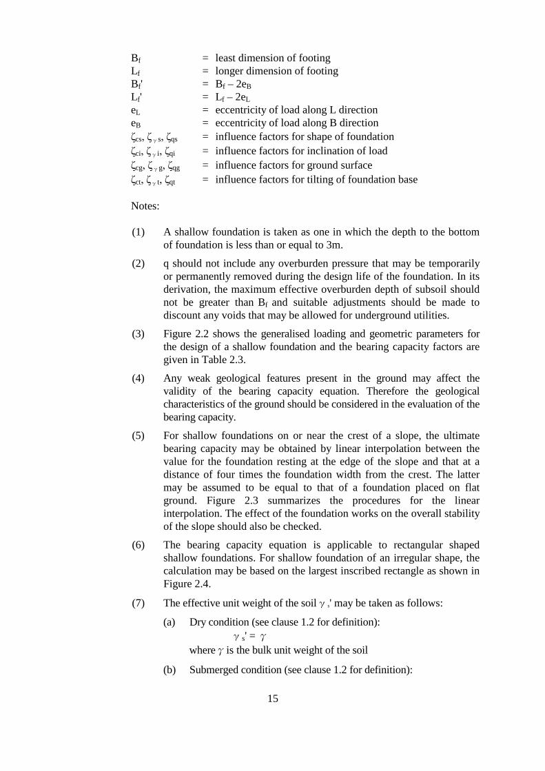
(1) A shallow foundation is taken as one in which the depth to the bottom of foundation is less than or equal to 3m.
(2) q should not include any overburden pressure that may be temporarily or permanently removed during the design life of the foundation. In its derivation, the maximum effective overburden depth of subsoil should not be greater than Bf and suitable adjustments should be made to discount any voids that may be allowed for underground utilities.
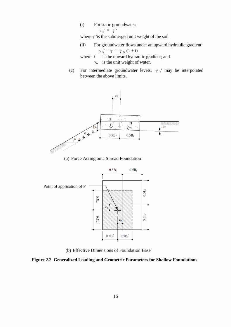
(3) Figure 2.2 shows the generalised loading and geometric parameters for the design of a shallow foundation and the bearing capacity factors are given in Table 2.3.
(4) Any weak geological features present in the ground may affect the validity of the bearing capacity equation. Therefore the geological characteristics of the ground should be considered in the evaluation of the bearing capacity.
(5) For shallow foundations on or near the crest of a slope, the ultimate bearing capacity may be obtained by linear interpolation between the value for the foundation resting at the edge of the slope and that at a distance of four times the foundation width from the crest. The latter may be assumed to be equal to that of a foundation placed on flat ground. Figure 2.3 summarizes the procedures for the linear interpolation. The effect of the foundation works on the overall stability of the slope should also be checked.
(6) The bearing capacity equation is applicable to rectangular shaped shallow foundations. For shallow foundation of an irregular shape, the calculation may be based on the largest inscribed rectangle as shown in Figure 2.4.
(7) The effective unit weight of the soilγs' may be taken as follows:
(a) Dry condition (see clause 1.2 for definition): γs' = γ
whereγis the bulk unit weight of the soil
(b) Submerged condition (see clause 1.2 for definition):
15
(i) For static groundwater: γs' = γ'
whereγ'is the submerged unit weight of the soil
(ii) For groundwater flows under an upward hydraulic gradient: γs' = γ – γw (1 + ί)
where ί is the upward hydraulic gradient; and γw is the unit weight of water.
(c) For intermediate groundwater levels, γ s' may be interpolated between the above limits.
(a) Force Acting on a Spread Foundation
(b) Effective Dimensions of Foundation Base
Point of application of P
Figure 2.2 Generalized Loading and Geometric Parameters for Shallow Foundations
16
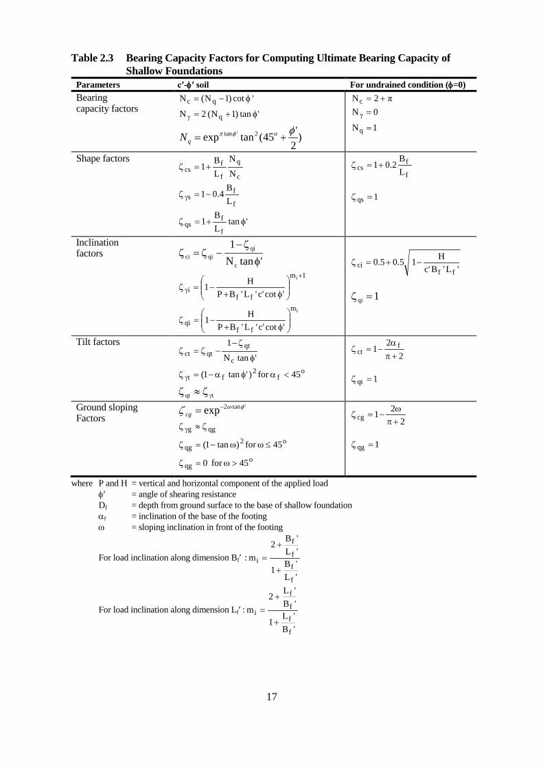
Table 2.3 Bearing Capacity Factors for Computing Ultimate Bearing Capacity of Shallow Foundations
Parameters c′-φ′ soil For undrained condition (φ=0) Bearing capacity factors
'1) cot (NN qc φ−=
'1) tan2 (NN q φ+=γ
)2 ' tan (45exp 2'tan φφp += o
qN
π2Nc +=
0N γ =
1Nq =
Shape factors
c
q
f
f cs N
N
L B
1+=ζ
f
f s L
B0.41−=ζ γ
'tan L B
1 f
f qs φ+=ζ
f
f cs L
B0.21+=ζ
1qs =ζ
Inclination factors
'tan N 1
c
qi qici φ
− ζ−= ζζ
1m
ff i
i
'cot'c'L'BP H1
+
γ
φ+ −=ζ
mi
ffqi 'cot'c'L'BP
H1
φ+ −=ζ
'L'B'c H10.50.5
ff ci −+=ζ
1qi =ζ
Tilt factors 'tanN
1
c
qt qtct φ
− ζ −= ζζ
o f
2 ft 45for )'tan(1 <aφ− a=ζ γ
tqt ≈ ζγζ
2 2
1 f ct p +
a−=ζ
1qt =ζ
Ground sloping Factors
'tan 2exp φωζ −= cg
qgg ≈ ζζ γ
o2 qg 45for )tan(1 ω ≤ω−=ζ
o qg 450 for ω >=ζ
2 21cg p +
ω−=ζ
1qg =ζ
where P and H = vertical and horizontal component of the applied load φ′ = angle of shearing resistance Df = depth from ground surface to the base of shallow foundation af = inclination of the base of the footing ω = sloping inclination in front of the footing
B ' f2 + L ' fFor load inclination along dimension Bf ′ : m =i B ' f1 + L ' f L ' f2 + B ' fFor load inclination along dimension Lf ′ : m =i L ' f1 + B ' f
17
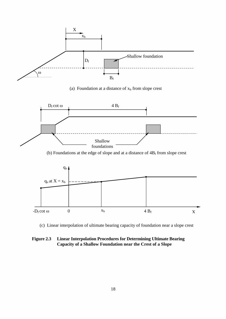
X xb
ω
Df
Bf
Shallow foundation
(a) Foundation at a distance of xb from slope crest
Df cot ω 4 Bf
Shallow foundations
(b) Foundations at the edge of slope and at a distance of 4Bf from slope crest
qu
qu at X = xb
-Df cot ω 0 xb 4 Bf
(c) Linear interpolation of ultimate bearing capacity of foundation near a slope crest
Figure 2.3 Linear Interpolation Procedures for Determining Ultimate Bearing Capacity of a Shallow Foundation near the Crest of a Slope
18
X
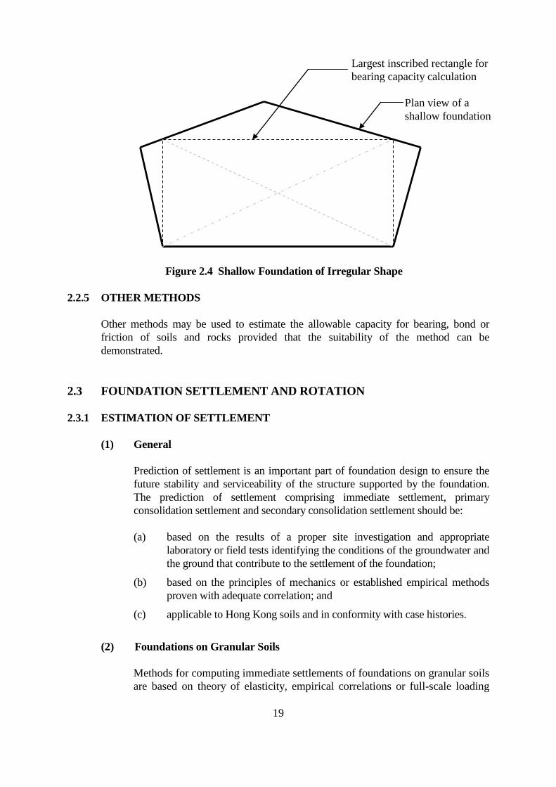
Largest inscribed rectangle for
Plan view of a shallow foundation
bearing capacity calculation
Figure 2.4 Shallow Foundation of Irregular Shape
2.2.5 OTHER METHODS
Other methods may be used to estimate the allowable capacity for bearing, bond or friction of soils and rocks provided that the suitability of the method can be demonstrated.
2.3 FOUNDATION SETTLEMENT AND ROTATION
2.3.1 ESTIMATION OF SETTLEMENT
(1) General
Prediction of settlement is an important part of foundation design to ensure the future stability and serviceability of the structure supported by the foundation. The prediction of settlement comprising immediate settlement, primary consolidation settlement and secondary consolidation settlement should be:
(a) based on the results of a proper site investigation and appropriate laboratory or field tests identifying the conditions of the groundwater and the ground that contribute to the settlement of the foundation;
(b) based on the principles of mechanics or established empirical methods proven with adequate correlation; and
(c) applicable to Hong Kong soils and in conformity with case histories.
(2) Foundations on Granular Soils
Methods for computing immediate settlements of foundations on granular soils are based on theory of elasticity, empirical correlations or full-scale loading
19

tests. Empirical correlations between foundation settlement and results of insitu tests such as standard penetration tests generally provide an acceptable solution for estimating the settlement of a shallow foundation on granular soils. Based on the theory of elasticity, the settlement of a shallow foundation can be calculated using an equation of the following form:
q B 'Fnet f oSe = Es
Where
Se = immediate settlement q net = mean net foundation bearing pressure (the net foundation bearing
pressure is the total foundation bearing pressure less effective overburden pressure at the base of the foundation)
Bf’ = effective width of the foundation Es = Young’s modulus of soil Fo = a coefficient whose value depends on the shape and dimensions of
the foundation, the variation of soil stiffness with depth, the thickness of compressible strata, Poisson’s ratio, the distribution of ground bearing pressure and the point at which the settlement is calculated. Reference should be made to GEO Publication No. 1/2006 for determination.
(3) Foundations on Fine-Grained Soils
For fine-grained soils, immediate settlement may be estimated using the same equation for granular soils. In addition to the immediate settlement, consolidation settlement should also be considered. An estimate of the consolidation settlement can be made using the settlement-time curve obtained from oedometer tests or other sources of reference that suit the conditions of the site. Consolidation settlement may be considered to consist of primary consolidation and secondary consolidation stage.
The primary consolidation settlement of a soil layer due to an applied loading depends on the relative magnitudes of the initial vertical effective stress acting on the soil and the effective preconsolidation pressure, and can be estimated as follows:
σ '+ ∆σν0 νFor σν0 '= σp '< σν0 '+ ∆σν Sp = Hs (CR log )σν0 '
σ '+ ∆σ σp ' ν0 νFor σν0 '< σp '< σν0 '+ ∆σν Sp = Hs (CR log + RR log )
σ ' σ ' p ν0
σ '+ ∆σν0 νFor σν0 '< σν0 '+ ∆σν < σp ' Sp = Hs (RR log )σν0 '
20
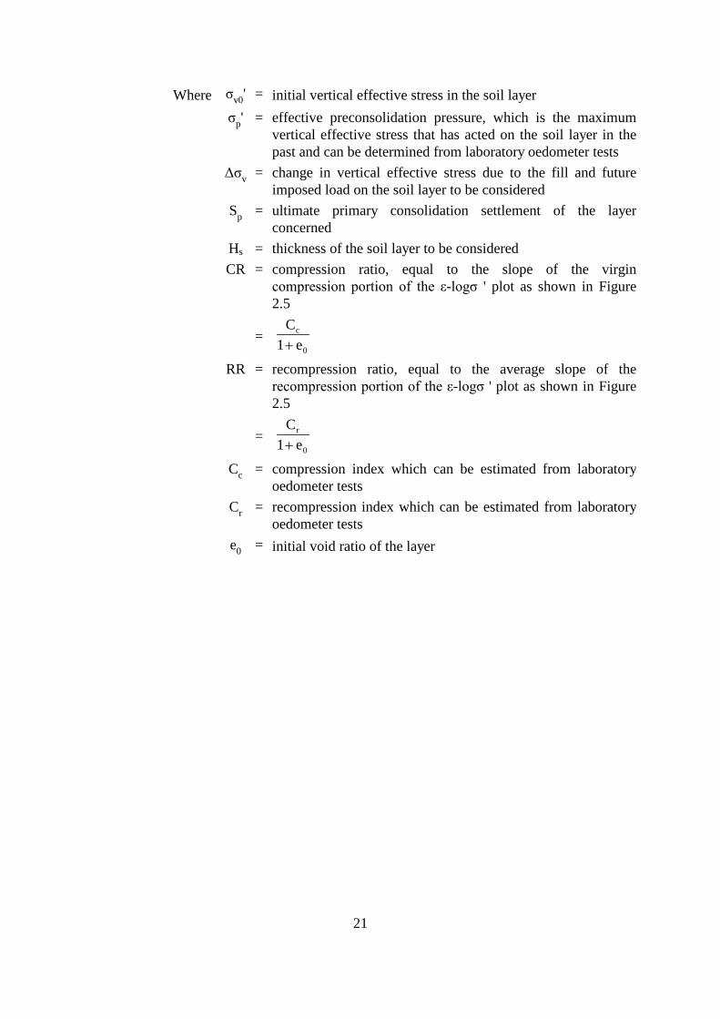
Where σv0 ' = initial vertical effective stress in the soil layer σp ' = effective preconsolidation pressure, which is the maximum
vertical effective stress that has acted on the soil layer in the past and can be determined from laboratory oedometer tests
Δσv = change in vertical effective stress due to the fill and future imposed load on the soil layer to be considered
Sp = ultimate primaryconcerned
consolidation settlement of the layer
Hs = thickness of the soil layer to be considered CR = compression ratio, equal to the slope of the virgin
compression portion of the ε-logσ ' plot as shown in Figure 2.5
= 0
c
e1 C +
RR = recompression ratio, equal to the average slope of the recompression portion of the ε-logσ ' plot as shown in Figure 2.5
= 0
r
e1 C +
Cc = compression index which can be estimated from laboratory oedometer tests
Cr = recompression index which can be estimated from laboratory oedometer tests
e0 = initial void ratio of the layer
21

ε
Virgin compression
Recompression Slope = compression ratio, CR
Average slope = recompression ratio, RR
Expansion
σ ': Vertical Effective Stress ε : Vertical Strain
Log σ '
Figure 2.5 Definition of Compressibility Parameters
The magnitude of secondary consolidation can be estimated as follows:
Ca tsSc = Ho log 1+ eo t p
where
Sc = secondary consolidation settlement Cα = secondary compression index eo = initial void ratio Ho = thickness of soils subject to secondary consolidation tp = time when primary consolidation completes ts = time for which secondary consolidation is allowed.
It can be assumed that the secondary consolidation settlement commences when 95% of the primary consolidation is reached. The rate of consolidation can be assessed using the coefficient of consolidation of the soil. The secondary compression index, Cα, can be estimated from laboratory oedometer tests.
22
(4) Young’s Modulus
The Young’s modulus Es of soils to be used for settlement estimations should be determined and verified by appropriate laboratory or in-situ tests. For shallow foundations, plate load tests may be required to verify the adopted value of Young’s modulus (see clause 4.2.2).
Care should be taken in determining the Young’s modulus of soils by the use of empirical correlations with the SPT N-value as it can be unsafe in some cases and over-conservative in others. For shallow foundations with design allowable bearing pressures not greater than 250 kPa, in the absence of more accurate data, the Young’s modulus Es (in MPa) of granular soils may be taken as 1 times the SPT N-value.
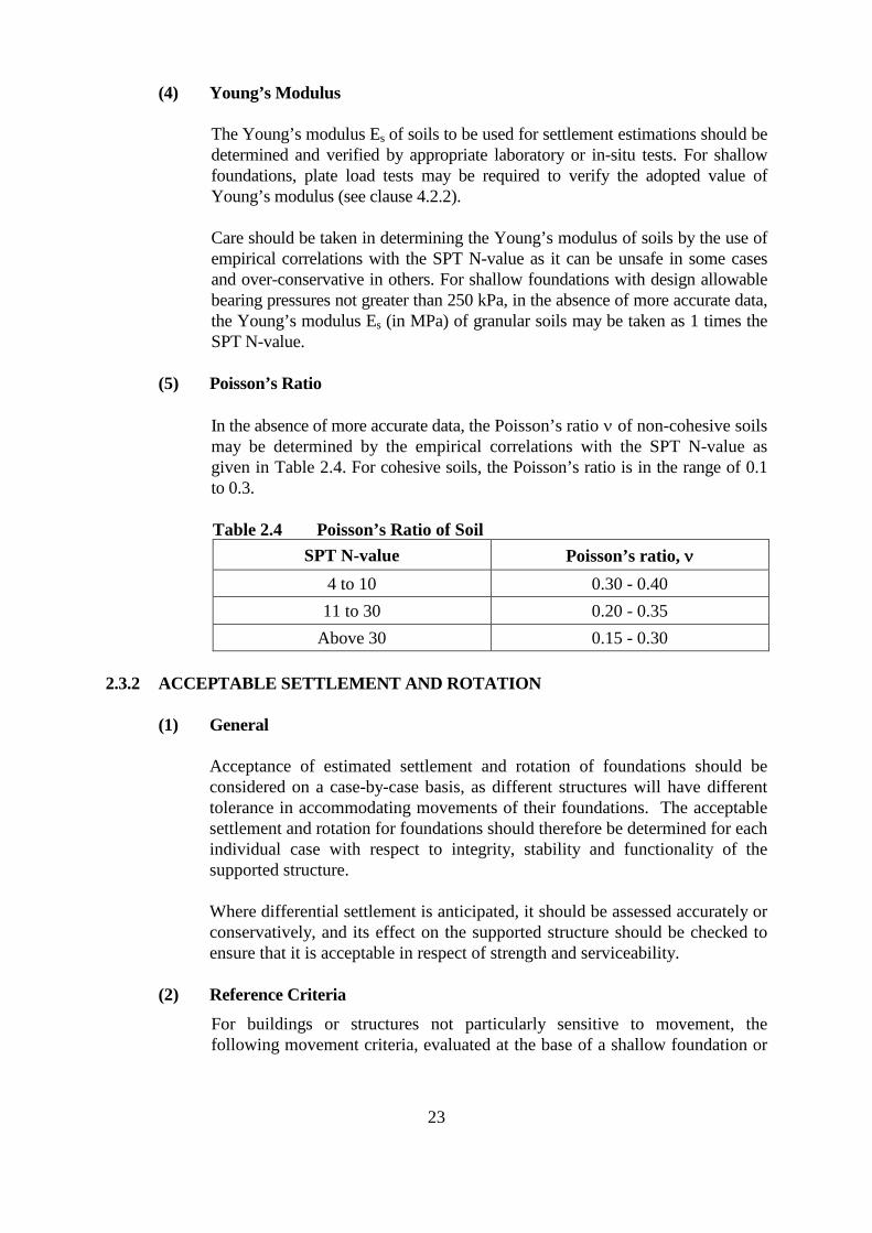
(5) Poisson’s Ratio
In the absence of more accurate data, the Poisson’s ratio ν of non-cohesive soils may be determined by the empirical correlations with the SPT N-value as given in Table 2.4. For cohesive soils, the Poisson’s ratio is in the range of 0.1 to 0.3.
Table 2.4 Poisson’s Ratio of Soil SPT N-value Poisson’s ratio, ν
4 to 10 0.30 - 0.40 11 to 30 0.20 - 0.35
Above 30 0.15 - 0.30
2.3.2 ACCEPTABLE SETTLEMENT AND ROTATION
(1) General
Acceptance of estimated settlement and rotation of foundations should be considered on a case-by-case basis, as different structures will have different tolerance in accommodating movements of their foundations. The acceptable settlement and rotation for foundations should therefore be determined for each individual case with respect to integrity, stability and functionality of the supported structure.
Where differential settlement is anticipated, it should be assessed accurately or conservatively, and its effect on the supported structure should be checked to ensure that it is acceptable in respect of strength and serviceability.
(2) Reference Criteria
For buildings or structures not particularly sensitive to movement, the following movement criteria, evaluated at the base of a shallow foundation or
23
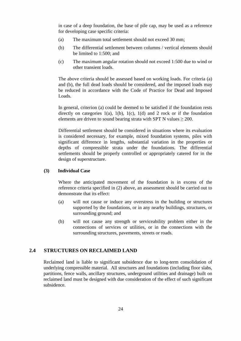
in case of a deep foundation, the base of pile cap, may be used as a reference for developing case specific criteria:
(a) The maximum total settlement should not exceed 30 mm;
(b) The differential settlement between columns / vertical elements should be limited to 1:500; and
(c) The maximum angular rotation should not exceed 1:500 due to wind or other transient loads.
The above criteria should be assessed based on working loads. For criteria (a) and (b), the full dead loads should be considered, and the imposed loads may be reduced in accordance with the Code of Practice for Dead and Imposed Loads.
In general, criterion (a) could be deemed to be satisfied if the foundation rests directly on categories 1(a), 1(b), 1(c), 1(d) and 2 rock or if the foundation elements are driven to sound bearing strata with SPT N values ≥ 200.
Differential settlement should be considered in situations where its evaluation is considered necessary, for example, mixed foundation systems, piles with significant difference in lengths, substantial variation in the properties or depths of compressible strata under the foundations. The differential settlements should be properly controlled or appropriately catered for in the design of superstructure.
(3) Individual Case
Where the anticipated movement of the foundation is in excess of the reference criteria specified in (2) above, an assessment should be carried out to demonstrate that its effect:
(a) will not cause or induce any overstress in the building or structures supported by the foundations, or in any nearby buildings, structures, or surrounding ground; and
(b) will not cause any strength or serviceability problem either in the connections of services or utilities, or in the connections with the surrounding structures, pavements, streets or roads.
2.4 STRUCTURES ON RECLAIMED LAND
Reclaimed land is liable to significant subsidence due to long-term consolidation of underlying compressible material. All structures and foundations (including floor slabs, partitions, fence walls, ancillary structures, underground utilities and drainage) built on reclaimed land must be designed with due consideration of the effect of such significant subsidence.
24
2.4.1 GENERAL DESIGN RULES
(a) Unless recommended otherwise, the lowest floor slabs of a building should not be designed as on-grade slabs.
(b) Floor slabs directly above a raft-type pile cap may be designed as on-grade.
(c) The following structures may also be designed as on-grade structures provided that they can be readily repaired or replaced if damaged by settlement:
(i) fence walls, landscaping structures and lightweight covered walkway; and
(ii) floor slabs used for car parking, loading and unloading, vehicular ramp or pedestrian pavement.
(d) For structures such as transformer rooms and pump houses, the foundations should be carried down through the reclaimed materials to a firm stratum with the lowest floor slabs designed as suspended.
(e) Underground utilities and drainage underneath a building should be supported by suspended floor slabs or pile caps. The pipe connection at the interface between the structurally supported portion and the on-grade portion of pipes should be designed to accommodate differential settlement due to the subsidence of the latter.
(f) Where significant settlement due to long-term consolidation of the ground is anticipated, measures should be provided in the pile cap design to mitigate the migration of soil into any void that may be formed underneath the pile cap due to consolidation of the ground below.
(g) The effect of negative skin friction on pile elements should be duly assessed.
2.4.2 ALTERNATIVE APPROACH
Where it is intended not to follow the design rules given in clause 2.4.1, the problem of differential and total settlement should be fully considered. The time-related total and differential settlement (including predicted time-settlement curves) should be assessed based on site-specific ground investigation, and measures to overcome or accommodate the problem should be provided.
To ensure the reliability of the time-settlement relationship estimated at the design stage, continuous settlement monitoring (through instrumentation) throughout the construction period should be carried out and the assessment of the settlement should be reviewed from time to time.
In the settlement assessment, reference may be made to the settlement measurements collected during the reclamation period and any previous settlement assessments made for the reclamation. However, such data should only be used as reference to the historical settlement characteristics of the site or as supplementary information to the site-specific assessment unless their accuracy can be guaranteed. The historical settlement record and settlement assessment for government reclamation, if available,
25
can be obtained from the government department who undertook the reclamation projects, usually the Civil Engineering and Development Department.
2.4.3 LONG TERM MONITORING AND/OR MAINTENANCE
Where the design of structures requires long-term monitoring and/or maintenance, the designer, through the AP, should alert the developer of such requirements and their implications and advise him to inform any prospective buyers who may have to bear the costs for such requirements.
2.4.4 RECLAIMED LAND WITH CONSOLIDATION SUBSTANTIALLY COMPLETED
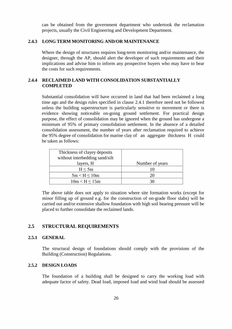
Substantial consolidation will have occurred in land that had been reclaimed a long time ago and the design rules specified in clause 2.4.1 therefore need not be followed unless the building superstructure is particularly sensitive to movement or there is evidence showing noticeable on-going ground settlement. For practical design purpose, the effect of consolidation may be ignored when the ground has undergone a minimum of 95% of primary consolidation settlement. In the absence of a detailed consolidation assessment, the number of years after reclamation required to achieve the 95% degree of consolidation for marine clay of an aggregate thickness H could be taken as follows:
Thickness of clayey deposits without interbedding sand/silt
layers, H Number of years H ≤ 5m 10
5m < H ≤ 10m 20 10m < H ≤ 15m 30
The above table does not apply to situation where site formation works (except for minor filling up of ground e.g. for the construction of on-grade floor slabs) will be carried out and/or extensive shallow foundation with high soil bearing pressure will be placed to further consolidate the reclaimed lands.
2.5 STRUCTURAL REQUIREMENTS
2.5.1 GENERAL
The structural design of foundations should comply with the provisions of the Building (Construction) Regulations.
2.5.2 DESIGN LOADS
The foundation of a building shall be designed to carry the working load with adequate factor of safety. Dead load, imposed load and wind load should be assessed
26
in accordance with the Code of Practice for Dead and Imposed Loads, Code of Practice on Wind Effects in Hong Kong and other relevant codes of practice. The imposed load should include buoyancy force and earth pressure. Buoyancy force should be assessed in accordance with clause 2.5.3. Earth pressure should be assessed by using recognized geotechnical engineering methods.
Where it is necessary to carry out foundation design based on a set of assumed loads, a detailed schedule of the assumed loads should be prepared and, before the commencement of the construction of the superstructure, it is necessary to demonstrate that the loads from detailed calculations of the superstructure do not exceed the assumed loads used in the foundation design.
2.5.3 UNDERGROUND WATER
The lateral or uplift/buoyancy force due to underground water acting on a structure or its foundation may be calculated based on either the highest anticipated groundwater level or the highest possible groundwater level, which are defined below.
(1) Highest Anticipated Groundwater Level
The highest anticipated groundwater level shall be the level derived from reliable data. In determining the highest anticipated groundwater level, the following conditions should be taken into consideration:
(a) the current and projected tidal variations;
(b) the design free surface water levels due to storm, wind surge and pounding;
(c) the design groundwater level taken into account the influences of rainfall, surface water run-off and groundwater movement;
(d) the damping of seawater tide influence by intervening ground;
(e) dewatering;
(f) the long term rise in sea level; and
(g) ground permeability.
The prediction of the highest anticipated groundwater level should be based on measurements of groundwater for a sufficiently long period that covers at least a wet season.
(2) Highest Possible Groundwater Level
The highest possible groundwater level shall be the level above which the groundwater would not rise under all possible extreme events such as severe rainfall, flooding and bursting of water mains. In the absence of reliable data to prove otherwise and except for low lying areas, the highest possible groundwater level may generally be taken as the ground surface of a building,
27
street, building works or street works. However, in low-lying areas such as reclamation, it may rise even above the ground surface.
2.5.4 RESISTANCE TO SLIDING, UPLIFT AND OVERTURNING
(1) General
The foundations shall be so designed and constructed to fulfil the requirements given in this clause.
(2) Design Based on Highest Anticipated Groundwater Table
Where the design is based on the highest anticipated groundwater table, a building or structure shall be so designed and constructed such that:
(a) the resistance to the sliding force acting thereon shall be at least 1.5 times the sliding force due to any loads;
(b) the resistance to the uplift force acting thereon shall be at least 1.5 times the uplift force due to any loads; and
(c) the resistance to the overturning moment acting thereon shall be at least 1.5 times the overturning moment due to wind loads, 1.5 times the overturning moment due to groundwater and 2 times the overturning moment due to loads other than wind loads and groundwater.
(3) Design Based on Highest Possible Groundwater Table
Where the design is based on the highest possible groundwater table, a building or structure shall be so designed and constructed such that:
(a) the resistance to the sliding force acting thereon shall be at least equal to the sum of 1.1 times the sliding force due to groundwater and 1.5 times the sliding force due to other loads;
(b) the resistance to the uplift force acting thereon shall be at least equal to the sum of 1.1 times the uplift force due to groundwater and 1.5 times the uplift force due to other loads; and
(c) the resistance to the overturning moment acting thereon shall be at least equal to the sum of 1.5 times the overturning moment due to wind loads, 1.1 times the overturning moment due to groundwater and 2 times the overturning moment due to loads other than wind loads and groundwater.
(4) Resistance
The resistance to the sliding force shall be calculated as the sum of the sliding resistance due to the minimum dead loads plus that due to any permitted sliding resistance.
The resistance to the uplift force shall be calculated as the sum of the downward force due to the minimum dead loads plus that due to any permitted anchorage resistance.
28
The resistance to the overturning moment shall be calculated as the sum of the stabilizing moment due to the minimum dead loads plus that due to any permitted anchorage resistance.
The minimum dead loads should be taken as the weight of the structural elements plus the weight of any permanent finishes and backfill. In the dead load calculations, conservatively assumed values or the actual thickness and densities of the finishes and the backfill should be used. Finishes and backfill that could be removed should be ignored in the calculations.
(5) Special Considerations for Marine Structures
Marine structures should also be designed and constructed such that the resistance to sliding, uplift and overturning satisfies the requirements of acceptable standards or codes of practice for design of maritime structures, such as “Port Works Design Manual” published by Civil Engineering and Development Department.
2.5.5 MATERIALS AND STRESSES
(1) General
Materials and stresses shall comply with the requirements of the Building (Construction) Regulations and the relevant codes of practice.
Where the permissible stress method is used in the structural design of foundation members, the working stress may be increased by not more than 25% where such increase is solely due to wind loads.
(2) Concrete
The concrete used for foundation elements shall comply with the Building (Construction) Regulations and the relevant codes of practice. Subject to the provisions of this Code, the design of the reinforced concrete elements of a foundation should be carried out in accordance with the Code of Practice for Structural Use of Concrete.
For cast-in-place concrete foundations, the concrete strength should be reduced by 20% where groundwater is likely to be encountered during concreting or where concrete is placed underwater.
The axial compressive stress on a driven precast concrete pile under working loads should not exceed 0.2fcu.
For marine foundations, concrete should not be inferior to grade C45 as required in clause 2.6.4. All concrete should be cast in dry condition as far as
29

possible. Where the concrete is placed under water, the concrete should be assumed as grade C25 for design purpose.
(3) Grout
The requirements for concrete given in this Code shall equally apply to grout.
(4) Steel
For driven steel bearing piles with a design safety factor on driving resistance of 2, the axial stress in the steel at working load should not exceed 30% of the yield stress.
For steel bearing piles installed in pre-bored holes or jacked to the required depth, in which no peak stresses due to impact are set up, the axial stress in the steel at working loads may be increased to 50% of the yield stress.
Structural element design may be carried out in accordance with the Code of Practice for the Structural Use of Steel, provided that the condition under any possible load test is considered.
For steel piles, the allowable bond stress between steel and grout (with a minimum characteristic strength of 30 MPa) may be taken as 400 kPa (or 320 kPa when grouting under water).
Shear studs designed in accordance with the Code of Practice for the Structural Use of Steel may be used to enhance the allowable bond stress provided that the overall allowable bond stress does not exceed 600 kPa (or 480 kPa when grouting under water).
Steel sections or other means as substitute for shear studs may also be considered.
The surface area for calculation of allowable steel/grout bond stress should be the total external surface area of the steel section.
For steel piles relying on the bond between steel and grout to resist tension or compression loads, the pile surface should be clean and free from loose mill scale, loose rust or any substance that may reduce the bond.
For corrosion protection of marine foundations, the guidelines as given in clause 2.6.4 should be followed.
30
2.6 CORROSION PROTECTION OF FOUNDATIONS
2.6.1 GENERAL
Foundations should be provided with adequate protections against corrosion, or alternatively, they should be suitably designed to allow for the effect of corrosion which may take place during their designed working life.
To ensure effective and economical designs for protection against corrosion, information on the presence of any corrosive material in the ground and the range of fluctuation of ground water table should be obtained.
2.6.2 CONCRETE FOUNDATIONS
Provisions for corrosion protection of concrete foundations should be given in the foundation plans where:
(a) sulphate, chloride, aggressive chemical or other agents causing deterioration is present in the ground;
(b) alkalis are present in the concrete and a high moisture content environment exists;
(c) the foundations are constructed on a landfill site; or
(d) damage by abrasion may occur.
To avoid the alkali-aggregate reaction occurring in reinforced concrete structures, the reactive alkali of concrete expressed as the equivalent sodium oxide per cubic metre of concrete should not exceed 3.0 kg.
2.6.3 STEEL PILES
Provisions for corrosion protection of steel piles should be given in the foundation plans where:
(a) sulphate, chloride, aggressive chemical or other agents causing deterioration is present in the ground;
(b) the piles are placed at the splash and tidal zones of the sea;
(c) the piles are in contact with other metals;
(d) stray direct electric current is present; or
(e) damage by abrasion may occur.
2.6.4 MARINE FOUNDATIONS
Corrosion protection of marine foundations should be provided in accordance with acceptable standards or codes of practice for design of maritime structures, such as “Port Works Design Manual Part 1” published by Civil Engineering and Development Department. The following should be considered as general guidelines:
31
(1) Concrete
Concrete should be of high density and low permeability. It should not be inferior to grade C45 and the water/cement ratio should not exceed 0.38. Condensed silica fume should be added to reduce the permeability of concrete. The cementitious content should be 380 to 450 kg/m3, of which the dry mass of condensed silica fume should be within 5 to 10% range by mass of the cementitious content.
Nominal concrete cover to all reinforcement in all exposure zone should be 75 mm.
Crack widths of concrete within tidal and splash zone should not exceed 0.1 mm under typical average long term loading conditions, which may be increased by a factor of 1.25 for flexural crack width design and control purpose.
Correct use of pulverized fuel ash in the concrete mix may increase resistance of concrete against sulphate attack.
(2) Steel
All structural steelwork above seabed level, whether fully immersed, within the tidal or splash zones, or generally above the splash zone, should be fully protected against corrosion for the design working life of the structure. Below seabed level, an allowance for corrosion loss of 0.05 mm per year on the outside face of steel is considered reasonable if no corrosion protection is carried out within this zone.
Stainless steel for use in marine environment should be of a grade which is absolutely free of any chloride. Common grade of stainless steel with the presence of chloride should not be used for marine works.
Steel embedded in concrete and steel in seawater in the same foundation should be isolated since the former is cathodic relative to the latter.
2.7 FOUNDATION PLANS
Foundation plans should consist of adequate and relevant information so as to demonstrate the entire physical and conceptual designs. A typical foundation plan should include the following two parts:
(1) A Foundation Plan :
(a) a block plan showing the location of the site;
32
(b) details showing the characteristic features of the site and environments including locations of ground investigation boreholes, adjacent and nearby buildings and structures with foundations, lands, streets, utility services, slopes, nullahs, retaining walls and the like;
(c) layout arrangement, identification, expected depths and founding levels, structural details and material specifications of the foundations;
(d) for piled foundations, item (c) should include size, shape, cut-off level and structural details of the pile element, as well as details of pile shoe, pile head, splices and the pile to pile cap connections;
(e) layout arrangement of the pile caps if applicable;
(f) bearing capacity of foundations and method of verification on site;
(g) specification of structural materials;
(h) magnitude of characteristic dead, imposed and wind loads and their critical combinations acting on the foundations (for piled foundations, this should be given for each pile or each group of piles);
(i) installation specifications, including the founding criteria, method of installation, etc.;
(j) for piled foundations, item (i) should include method of controlling and monitoring the verticality, inclination and alignment of the piles during installation, the maximum number of piling rigs allowed to be concurrently driving piles at any one time for percussive piling in vibration sensitive sites, method of overcoming underground obstruction, etc.;
(k) where dynamic pile driving formula is used, the parameters for the assessment of the ultimate pile capacity, such as the hammer efficiency, efficiency of blow and penetration of pile per hammer blow; and
(l) proposals of precautionary and protective measures, monitoring plan and contingency plans to be implemented before and during the course of the construction works (see clause 7.2).
(2) Supporting Documents:
(a) site investigation report with results of ground investigation, field and laboratory tests and photographs of all the soil samples and rock cores taken;
(b) design calculations based on recognized foundation engineering principles;
33
(c) assessment on the effects of the proposed foundation works on adjacent and nearby buildings, structures, lands, streets, utility services, slopes, nullahs and retaining walls etc.; and
(d) for foundation works that may induce vibration or ground movement, a PR Plan (see clause 7.2.7).
2.8 FOUNDATION DESIGN IN SCHEDULED AREAS
2.8.1 GENERAL
In accordance with the Fifth Schedule to the Buildings Ordinance, there are five Scheduled Areas specified in Hong Kong at present. These areas are:
Area No. Scheduled Areas
1 Mid-levels 2 North-west New Territories 3 Railway Protection Areas 4 Ma On Shan 5 Sewage Tunnel Protection Areas
Particular requirements for foundation design in the Scheduled Areas are given in the relevant PNAP issued by the Building Authority. When planning and designing foundations in the Scheduled Areas, reference should be made to these PNAP.
2.8.2 FOUNDATION DESIGN IN SCHEDULED AREA NOS. 2 AND 4
2.8.2.1 GENERAL
The geology of Scheduled Area No. 2 (North-west New Territories) and Scheduled Area No. 4 (Ma On Shan) comprises superficial deposits overlying metamorphosed sedimentary strata (meta-siltstones, meta-sandstones and marble) as well as igneous rocks. The marble usually has a karstic upper surface with solution features. Large cavities with or without infilled material may be present within the marble.
Foundation design in karst marble requires careful consideration of the karst morphology, loading intensity and layout of load bearing elements. The main problem affecting the design is the potential presence of overhangs, channels and cavities. The stability of the pile foundation will depend on the particular geometry of such karst features and the rock mass properties.
Given that karstic marble and the related complex and adverse geological features could give rise to difficulties and uncertainties in foundation design and construction, ensuring sufficient geotechnical input is of the essence.
34
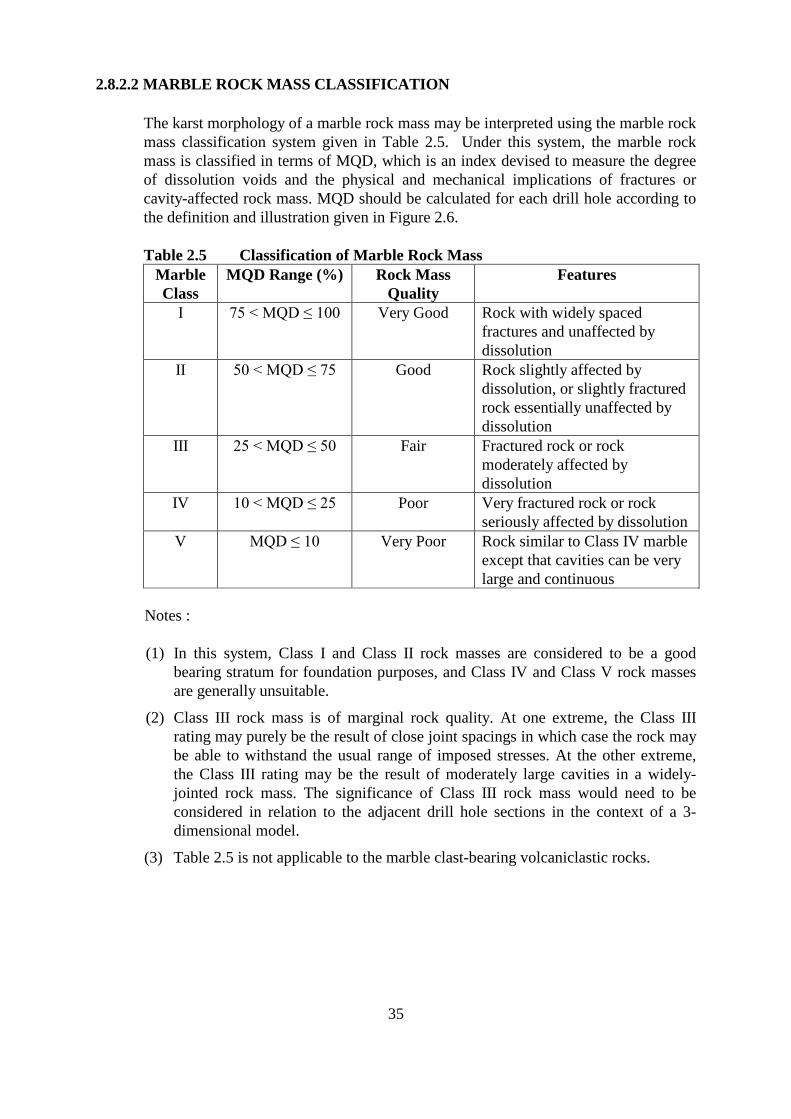
2.8.2.2 MARBLE ROCK MASS CLASSIFICATION
The karst morphology of a marble rock mass may be interpreted using the marble rock mass classification system given in Table 2.5. Under this system, the marble rock mass is classified in terms of MQD, which is an index devised to measure the degree of dissolution voids and the physical and mechanical implications of fractures or cavity-affected rock mass. MQD should be calculated for each drill hole according to the definition and illustration given in Figure 2.6.
Table 2.5 Classification of Marble Rock Mass Marble Class
MQD Range (%) Rock Mass Quality
Features
I 75 < MQD ≤ 100 Very Good Rock with widely spaced fractures and unaffected by dissolution
II 50 < MQD ≤ 75 Good Rock slightly affected by dissolution, or slightly fractured rock essentially unaffected by dissolution
III 25 < MQD ≤ 50 Fair Fractured rock or rock moderately affected by dissolution
IV 10 < MQD ≤ 25 Poor Very fractured rock or rock seriously affected by dissolution
V MQD ≤ 10 Very Poor Rock similar to Class IV marble except that cavities can be very large and continuous
Notes :
(1) In this system, Class I and Class II rock masses are considered to be a good bearing stratum for foundation purposes, and Class IV and Class V rock masses are generally unsuitable.
(2) Class III rock mass is of marginal rock quality. At one extreme, the Class III rating may purely be the result of close joint spacings in which case the rock may be able to withstand the usual range of imposed stresses. At the other extreme, the Class III rating may be the result of moderately large cavities in a widely-jointed rock mass. The significance of Class III rock mass would need to be considered in relation to the adjacent drill hole sections in the context of a 3dimensional model.
(3) Table 2.5 is not applicable to the marble clast-bearing volcaniclastic rocks.
35
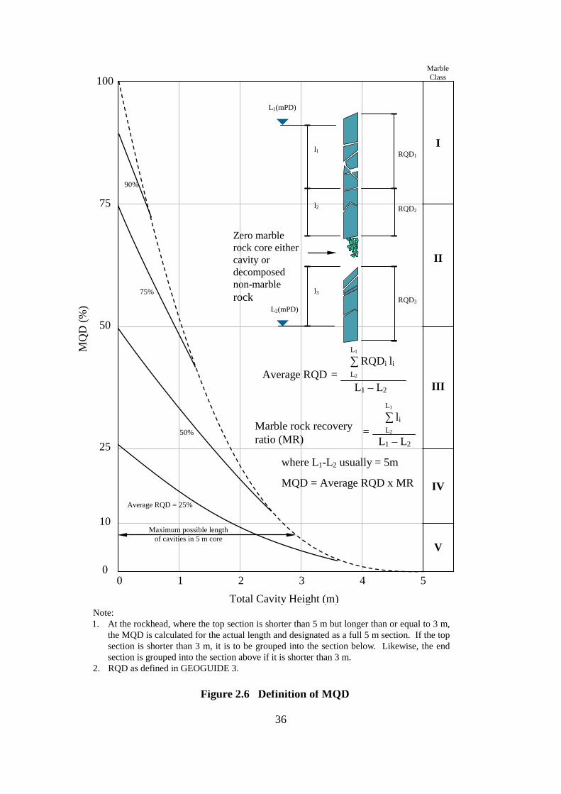
Total Cavity Height (m)
Marble
MQ
D (%
) Class 100
75
50
25
10
0 0 1 2 3 4 5
90%
75%
50%
Average RQD = 25%
I
II
III
IV
V Maximum possible length
of cavities in 5 m core
RQD1
L2(mPD)
L1(mPD)
l3
RQD2
RQD3
l2
l1
Average RQD L2=
Marble rock recovery ratio (MR)
= L2
where L1-L2 usually = 5m
MQD = Average RQD x MR
Zero marble rock core either cavity or decomposed non-marble rock
L1
∑ li
L1 – L2
L1
∑ RQDi li
L1 – L2
Note: 1. At the rockhead, where the top section is shorter than 5 m but longer than or equal to 3 m,
the MQD is calculated for the actual length and designated as a full 5 m section. If the top section is shorter than 3 m, it is to be grouped into the section below. Likewise, the end section is grouped into the section above if it is shorter than 3 m.
2. RQD as defined in GEOGUIDE 3.
Figure 2.6 Definition of MQD
36
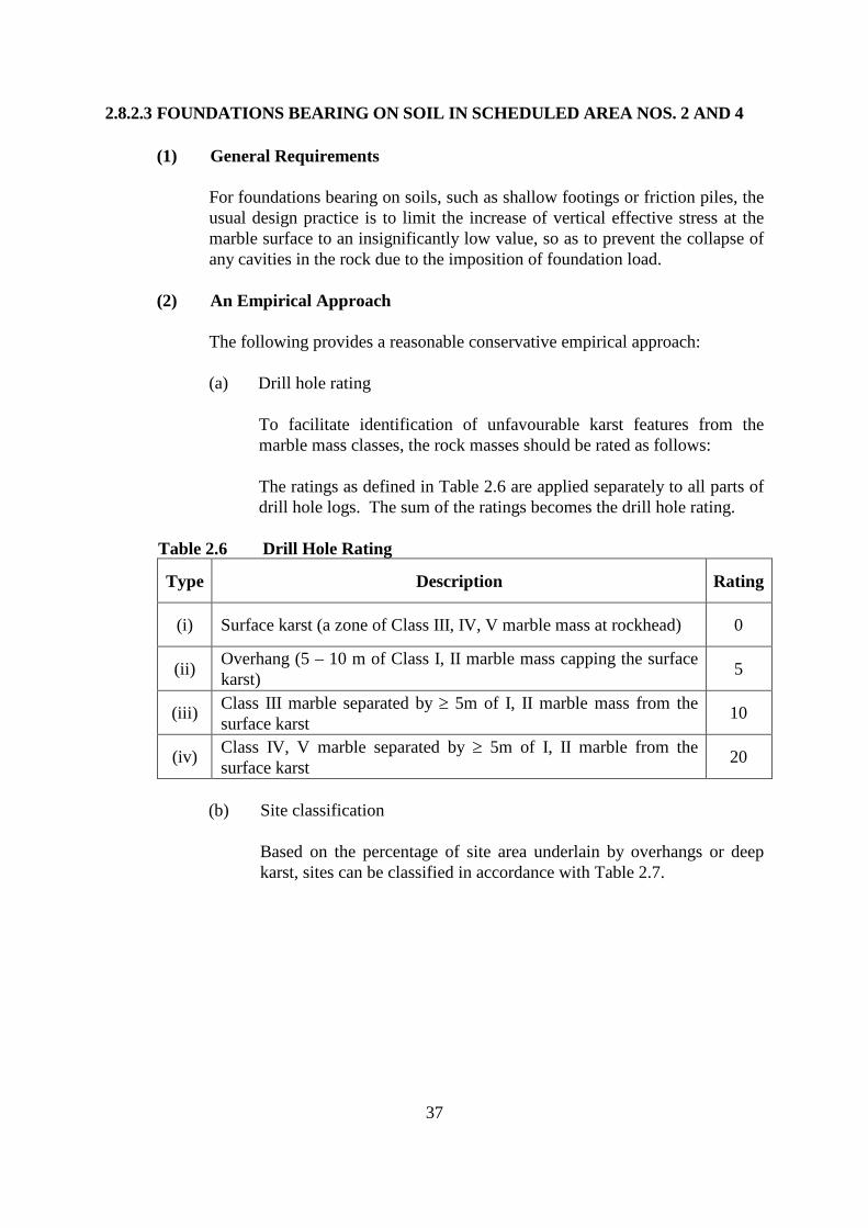
2.8.2.3 FOUNDATIONS BEARING ON SOIL IN SCHEDULED AREA NOS. 2 AND 4
(1) General Requirements
For foundations bearing on soils, such as shallow footings or friction piles, the usual design practice is to limit the increase of vertical effective stress at the marble surface to an insignificantly low value, so as to prevent the collapse of any cavities in the rock due to the imposition of foundation load.
(2) An Empirical Approach
The following provides a reasonable conservative empirical approach:
(a) Drill hole rating
To facilitate identification of unfavourable karst features from the marble mass classes, the rock masses should be rated as follows:
The ratings as defined in Table 2.6 are applied separately to all parts of drill hole logs. The sum of the ratings becomes the drill hole rating.
Table 2.6 Drill Hole Rating
Type Description Rating
(i) Surface karst (a zone of Class III, IV, V marble mass at rockhead) 0
(ii) Overhang (5 – 10 m of Class I, II marble mass capping the surface karst) 5
(iii) Class III marble separated by ≥ 5m of I, II marble mass from the surface karst 10
(iv) Class IV, V marble separated by ≥ 5m of I, II marble from the surface karst 20
(b) Site classification
Based on the percentage of site area underlain by overhangs or deep karst, sites can be classified in accordance with Table 2.7.
37
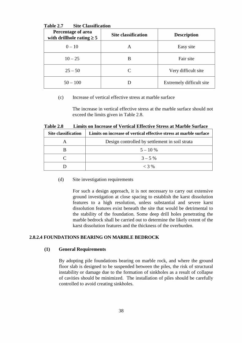
Table 2.7 Site Classification Percentage of area
with drillhole rating ≥ 5 Site classification Description
0 – 10 A Easy site
10 – 25 B Fair site
25 – 50 C Very difficult site
50 – 100 D Extremely difficult site
(c) Increase of vertical effective stress at marble surface
The increase in vertical effective stress at the marble surface should not exceed the limits given in Table 2.8.
Table 2.8 Limits on Increase of Vertical Effective Stress at Marble Surface Site classification Limits on increase of vertical effective stress at marble surface
A Design controlled by settlement in soil strata
B 5 – 10 %
C 3 – 5 %
D < 3 %
(d) Site investigation requirements
For such a design approach, it is not necessary to carry out extensive ground investigation at close spacing to establish the karst dissolution features to a high resolution, unless substantial and severe karst dissolution features exist beneath the site that would be detrimental to the stability of the foundation. Some deep drill holes penetrating the marble bedrock shall be carried out to determine the likely extent of the karst dissolution features and the thickness of the overburden.
2.8.2.4 FOUNDATIONS BEARING ON MARBLE BEDROCK
(1) General Requirements
By adopting pile foundations bearing on marble rock, and where the ground floor slab is designed to be suspended between the piles, the risk of structural instability or damage due to the formation of sinkholes as a result of collapse of cavities should be minimized. The installation of piles should be carefully controlled to avoid creating sinkholes.
38
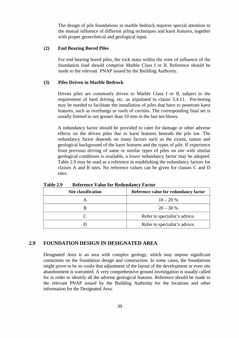
The design of pile foundations in marble bedrock requires special attention to the mutual influence of different piling techniques and karst features, together with proper geotechnical and geological input.
(2) End Bearing Bored Piles
For end bearing bored piles, the rock mass within the zone of influence of the foundation load should comprise Marble Class I or II. Reference should be made to the relevant PNAP issued by the Building Authority.
(3) Piles Driven to Marble Bedrock
Driven piles are commonly driven to Marble Class I or II, subject to the requirement of hard driving, etc. as stipulated in clause 5.4.11. Pre-boring may be needed to facilitate the installation of piles that have to penetrate karst features, such as overhangs or roofs of cavities. The corresponding final set is usually limited to not greater than 10 mm in the last ten blows.
A redundancy factor should be provided to cater for damage or other adverse effects on the driven piles due to karst features beneath the pile toe. The redundancy factor depends on many factors such as the extent, nature and geological background of the karst features and the types of pile. If experience from previous driving of same or similar types of piles on site with similar geological conditions is available, a lower redundancy factor may be adopted. Table 2.9 may be used as a reference in establishing the redundancy factors for classes A and B sites. No reference values can be given for classes C and D sites.
Table 2.9 Reference Value for Redundancy Factor Site classification Reference value for redundancy factor
A 10 – 20 %
B 20 – 30 %
C Refer to specialist’s advice.
D Refer to specialist’s advice.
2.9 FOUNDATION DESIGN IN DESIGNATED AREA
Designated Area is an area with complex geology, which may impose significant constraints on the foundation design and construction. In some cases, the foundations might prove to be so costly that adjustment of the layout of the development or even site abandonment is warranted. A very comprehensive ground investigation is usually called for in order to identify all the adverse geological features. Reference should be made to the relevant PNAP issued by the Building Authority for the locations and other information for the Designated Area.
39
2.10 FOUNDATION DESIGN IN SLOPING GROUND
Where the foundation has imposed additional loads on slopes or retaining walls, or the groundwater regime has been affected, the stability of the affected slopes or retaining walls should be checked as part of the foundation design.
40
3. SITE INVESTIGATION
3.1 GENERAL
An adequate site investigation should be undertaken to provide all the necessary information for the design and construction of foundations. For this purpose, a site investigation report should be prepared, giving details of the results of any documentary studies, site surveys and ground investigations, together with the appraisal of the surface and subsurface conditions of the site.
Site investigations should be carried out in accordance with GEOGUIDE 2 and GEOGUIDE 3, and should comply with the provisions of this code of practice.
3.2 DOCUMENTARY STUDIES
Documentary studies should be carried out before planning a site investigation. Useful information is available in the Geotechnical Information Unit of the Civil Engineering Library in the Civil Engineering and Development Department. However, care should be taken in using any ground investigation data obtained from previous building projects. The accuracy of such data should be verified before they are used in the design of foundations. Any doubtful data should be discarded.
3.3 SITE SURVEY
The site survey should include a detailed survey of the land, structures and services within and adjacent to the site. All relevant information obtained should be shown on the foundation plan.
(1) Topographical Survey
The topographical survey should identify the topography of the area, including the nature and conditions of the land within and adjacent to the site. The following should be checked to identify any sloping conditions within or nearby the site:
(a) any land with an average gradient measured from boundary to boundary, or across any 50 m strip of the site, greater than 15°; and
(b) any slope with an average gradient greater than 15° within the site or within 50 m from the site boundaries.
41
(2) Geological Study
The geological study should identify all geological information of the site, including any particular geological features, rock outcrops, previous landslides and site formation works, etc. for developing the geological model and ground model.
The key requirements for the geological and ground models in respect of foundations include:
(a) early recognition of potential geological and/or geotechnical complexity;
(b) identification of relevant variations in geology, weathering profiles and material properties which may affect foundation performance;
(c) assessment of external factors which may affect or be affected by the foundation, such as the groundwater regime, lateral loading from slopes, and slope or land stability issues during and after foundation construction;
(d) identification of key areas of geotechnical uncertainty for further investigation; and
(e) verification and updating of the geological model and ground model during construction.
(3) Survey of Structures
The survey of structures should identify the following:
(a) any existing building, structure and foundation in the vicinity of the site; and
(b) any existing retaining wall within and adjacent to the site.
The stability and structural conditions of any nearby existing buildings and structures, in particular pre-war buildings, appendages, party walls etc., which are likely to be affected by the proposed foundation works, should be assessed. Proper records including photographs of any existing building defects should be kept for future reference.
The information on the foundations of such buildings or structures should be obtained for the assessment. Where such information is not available, inspection by trial pit or by drilling vertical and horizontal investigation holes through the foundations may have to be carried out to establish the information on the dimension and material of the foundations.
(4) Survey of any Disused Tunnel, Culvert, Nullah or Stream Course
The survey should identify any disused tunnel, culvert, nullah, stream course or ground anchor or soil nails or the like within and nearby the site.
42
The presence of any disused tunnel may have an important bearing on the design and construction of the foundations, and may lead to restrictions to be imposed on foundation design. Records of disused tunnels may be obtained from the Geotechnical Information Unit of the Civil Engineering Library in Civil Engineering and Development Department.
The presence of any culverts, nullahs or stream courses may seriously prejudice the proposed development. As a general principle, no building should be permitted over a main arterial storm water nullah.
(5) Survey of Underground Services
The site investigation should identify all the underground services within and nearby the site. The common types of underground services include water mains, sewage tunnels, electricity cables, gas mains, drainage pipes, telephone and other communication ducts. Reference should be made to the Code of Practice on Monitoring and Maintenance of Water-Carrying Services Affecting Slopes regarding the methods of detecting underground water-carrying services issued by ETWB.
Information regarding underground services, as well as the amount of settlement or movement that they could tolerate, may be obtained from the relevant government departments and utility companies. Such information is often indicative in nature, and should be verified on site.
3.4 GROUND INVESTIGATION
3.4.1 GENERAL
Ground investigation works involve the field works carried out to obtain information on the ground conditions, such as drillholes, excavation and probing, installation of instruments, sampling and field testing, and the laboratory testing of samples obtained from such operations.
All ground investigation field works, except field density tests, should be carried out by a RSC (Ground Investigation Field Works) and under appropriate supervision requirements given in the Code of Practice for Site Supervision, whereas all laboratory testing of samples and field density tests should be carried out by laboratories accredited under the HOKLAS. The test results should be reported in a HOKLAS endorsed test certificate.
Sufficient ground investigation works should be carried out to ensure that adequate information on the subsurface conditions within and nearby the site can be obtained prior to the design of the foundation.
43
If an existing ground investigation result that has been carried out without complying the supervision requirements given in the Code of Practice for Site Supervision is to be used, reliability of such record should be ascertained.
3.4.2 SUPERVISION FOR GROUND INVESTIGATION WORKS
Proper supervision should be provided for the carrying out of all ground investigation works. To ensure quality of the works, supervision for the different stages of pre-design ground investigation field works should comply with the requirements set out in the relevant PNAP or code of practice issued by the Buildings Department.
3.4.3 PREPARATION OF GROUND INVESTIGATION REPORTS
To substantiate the design of the foundation, a proper ground investigation report should be compiled. The ground investigation report should include adequate information for the design of the foundation and the subsequent construction works, and/or for other purposes such as site formation works, when required. For detailed requirements of the contents of ground investigation reports, reference should be made to GEOGUIDE 2, and the relevant PNAP and code of practice issued by the Buildings Department.
3.4.4 SOIL AND ROCK SAMPLING
Good quality soil samples and continuous rock cores from drillholes should be obtained for both geological logging and laboratory testing. Laboratory tests should be carried out for characterizing the materials and determining the relevant design parameters. These include classification tests to establish the general properties of the ground and strength and compressibility tests to determine the input parameters for foundation design based on principles of soil and rock mechanics.
3.4.5 NUMBER AND DISPOSITION OF BOREHOLES/TRIAL PITS
The disposition and spacing of boreholes/trial pits should be such as to reveal any significant changes in properties, thickness or depth of the strata. The number of boreholes/trial pits required will vary with the size, type and performance requirements of the structure, the general condition of the site and the completeness or otherwise of available geological records.
It should be noted that the ground conditions in Hong Kong, including bedrock levels, may vary significantly within a short distance. The number of boreholes/trial pits should be sufficient to reveal such variation.
Where it is intended to have the foundation rest on rock, sufficient boreholes should be provided to construct a representative geological model and establish the rockhead level for foundation design.
44
3.4.6 DEPTH OF GROUND INVESTIGATION
Boreholes and trial pits should be carried out to sufficient depth such that all strata that are likely to be affected by the foundation loads will be adequately explored. The depth of ground investigation will depend on the type of the structure, the size, shape and disposition of the loaded areas and the nature of the strata. In general, the following should be considered:
(a) Care should be taken to ensure that boulders are not mistaken for bedrock, particularly on sites where borings are made through highly weathered rock. Where bedrock is encountered, it should be proved by coring to a minimum depth of 5 m.
(b) Where compressible cohesive soils are likely to contribute significantly to the settlement of the foundations, the investigation should reach such depth where stress increase would cause insignificant strain or displacement.
(c) For the design of a pile foundation or for the settlement analysis of the foundation, the exploration should be deep enough to cover the characteristics of the underlying strata.
(d) For spread footings, the investigation depth should be: (i) 5m into rock; or (ii) a depth that can be readily demonstrated that the induced strain
and displacement are negligible.
Due to the complex ground conditions in Scheduled Area Nos. 2 and 4 and the Designated Area of Northshore Lantau, more extensive ground investigation works are normally required (see clauses 3.5 and 3.6).
3.4.7 GROUNDWATER
Groundwater may be critical in foundation design and construction. Particularly where dewatering is likely to be required, adequate information on groundwater and geological conditions including permeability, compressibility and consolidation characteristics of the various soil strata, particle size analyses and other test results relevant to the consideration of dewatering activities and preventive measures against settlement should be obtained.
It is generally necessary to install standpipes or piezometers to measure the groundwater levels over an extended period of time for accurate identification of the groundwater conditions and verification of design assumptions.
Where the groundwater or soil may contain constituents in amounts sufficient to damage or affect the foundation structures, chemical analysis of samples of the groundwater and soil should be carried out. Protection of the foundation structures from the effect of such constituents or other appropriate measures should be provided if found necessary.
45
3.5 GROUND INVESTIGATION IN SCHEDULED AREAS
Ground investigation works in the Scheduled Areas are subject to special control under the Buildings Ordinance and Building Regulations. Approval of the ground investigation plan as prescribed under regulation 8(1)(l) of the Building (Administration) Regulations and consent from the Building Authority are required before the commencement of works on site.
Particular requirements for ground investigation in the Scheduled Areas are given in the relevant PNAP issued by the Building Authority. When planning the ground investigation for foundation works in the Scheduled Areas, reference should be made to these PNAP.
3.6 GROUND INVESTIGATION WITHIN THE DESIGNATED AREA
Ground investigation works within the Designated Area are subject to special administrative procedures, including supervision requirements in accordance with the Code of Practice for Site Supervision.
Ground investigation for a site within the Designated Area is best carried out in stages, with the initial stages of the investigation being completed prior to the finalization of general building plans for the site. Some deep drillholes may be required, in particular to check for the possible presence of deep weathering profiles. Geological input to the planning of the ground investigation is of the essence.
46
4. SHALLOW FOUNDATIONS
4.1 GENERAL REQUIREMENTS
A shallow foundation should be structurally adequate to sustain all the applied loads and transmit them safely to the ground without undue settlement. It should generally be constructed of reinforced concrete, and rest on a rock or soil stratum with adequate bearing capacity at a shallow depth from ground level.
A shallow foundation should neither overload the foundations or structures of adjacent buildings or the ground supporting such foundations or structures, nor render any instability to any hillside or slope, nor interfere with any drain, nullah, sewer or other services in its vicinity.
4.2 ALLOWABLE BEARING PRESSURE AND SETTLEMENT
4.2.1 SHALLOW FOUNDATIONS ON CATEGORIES 1(a), 1(b), 1(c), 1(d) OR 2 ROCK
The allowable bearing pressure may be determined in accordance with clause 2.2.
4.2.2 SHALLOW FOUNDATIONS ON SOIL
(1) Design Procedures
The allowable bearing pressure should be determined in accordance with clause 2.2. The settlements of the foundation should be estimated and checked in accordance with clauses 2.3.1 and 2.3.2 respectively.
A flow chart of procedures for design of shallow foundations is given in Figure 4.1.
47
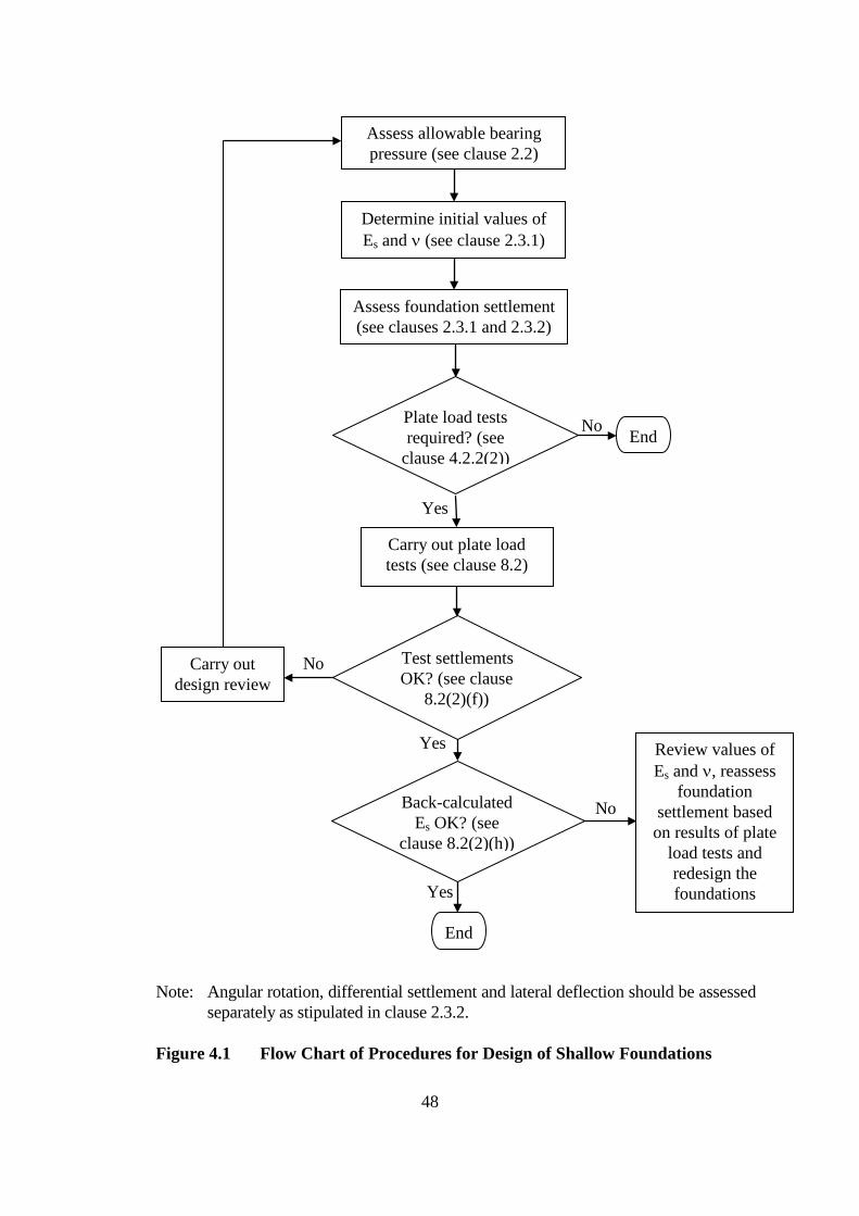
Yes
Determine initial values of Es and ν (see clause 2.3.1)
Assess foundation settlement (see clauses 2.3.1 and 2.3.2)
Plate load tests required? (see
clause 4.2.2(2))
Test settlements OK? (see clause
8.2(2)(f))
Carry out plate load tests (see clause 8.2)
No End
Yes
Assess allowable bearing pressure (see clause 2.2)
Back-calculated Es OK? (see
clause 8.2(2)(h))
Carry out design review
No
End
Review values of Es and ν, reassess
foundation settlement based on results of plate
load tests and redesign the foundations
No
Yes
Yes
Note: Angular rotation, differential settlement and lateral deflection should be assessed separately as stipulated in clause 2.3.2.
Figure 4.1 Flow Chart of Procedures for Design of Shallow Foundations
48
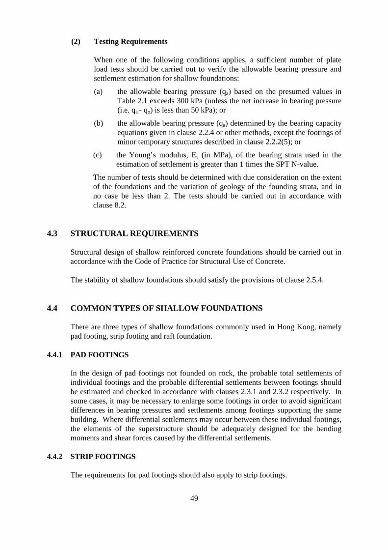
(2) Testing Requirements
When one of the following conditions applies, a sufficient number of plate load tests should be carried out to verify the allowable bearing pressure and settlement estimation for shallow foundations:
(a) the allowable bearing pressure (qa) based on the presumed values in Table 2.1 exceeds 300 kPa (unless the net increase in bearing pressure (i.e. qa - qo) is less than 50 kPa); or
(b) the allowable bearing pressure (qa) determined by the bearing capacity equations given in clause 2.2.4 or other methods, except the footings of minor temporary structures described in clause 2.2.2(5); or
(c) the Young’s modulus, Es (in MPa), of the bearing strata used in the estimation of settlement is greater than 1 times the SPT N-value.
The number of tests should be determined with due consideration on the extent of the foundations and the variation of geology of the founding strata, and in no case be less than 2. The tests should be carried out in accordance with clause 8.2.
4.3 STRUCTURAL REQUIREMENTS
Structural design of shallow reinforced concrete foundations should be carried out in accordance with the Code of Practice for Structural Use of Concrete.
The stability of shallow foundations should satisfy the provisions of clause 2.5.4.
4.4 COMMON TYPES OF SHALLOW FOUNDATIONS
There are three types of shallow foundations commonly used in Hong Kong, namely pad footing, strip footing and raft foundation.
4.4.1 PAD FOOTINGS
In the design of pad footings not founded on rock, the probable total settlements of individual footings and the probable differential settlements between footings should be estimated and checked in accordance with clauses 2.3.1 and 2.3.2 respectively. In some cases, it may be necessary to enlarge some footings in order to avoid significant differences in bearing pressures and settlements among footings supporting the same building. Where differential settlements may occur between these individual footings, the elements of the superstructure should be adequately designed for the bending moments and shear forces caused by the differential settlements.
4.4.2 STRIP FOOTINGS
The requirements for pad footings should also apply to strip footings.
49
The founding conditions for a strip footing should be consistent to avoid differential settlements along its length. However, where differential settlements along its length may occur, the strip footing should be designed with adequate strength to resist the effect of the differential settlement.
4.4.3 RAFT FOUNDATIONS
The requirements for pad and strip footings should also apply to raft foundations.
Where it is necessary to design a raft for differential settlements, the raft should be designed with adequate strength to resist the effect of the differential settlements in both directions.
50
5. PILE FOUNDATIONS
5.1 GENERAL
All pile foundations should be durable, of adequate load carrying capacity and of a recognized type suitable for the ground conditions. The piles should be able to withstand the expected wear and deterioration throughout the intended design working life of the superstructure that they support.
The allowable load on pile foundations shall be determined by:
(a) acceptable foundation engineering principles; or
(b) tests on the foundations on site,
with an adequate factor of safety appropriate to the type of pile, taking into account the ground conditions, the method of installation, group effects and the allowable displacements of the structures supported by the foundation.
5.1.1 RECOGNIZED TYPES OF PILE FOUNDATIONS
A recognized type of pile foundation is a piling system which has been proved satisfactory to the Building Authority and incorporated into a list which is available from the homepage of the Buildings Department.
The RSE usually in conjunction with the RSC experienced in a piling system which is not a recognized type may seek recognition of the system by submitting all technical details of the system to the Building Authority, including material specification, manufacturing process, method of installation, method of assessing pile capacity, applicability relating to ground conditions and selected examples of uses of the system elsewhere, if applicable. A demonstration of the performance of the system is usually required.
Application for a recognized type of pile should be made prior to seeking approval of foundation plans using such type of pile whenever possible.
5.1.2 GROUP EFFECT
A pile group exists when frictional piles installed in soil are closely placed such that the load carrying capacity and settlement behaviour of a pile may be affected by other piles.
In such case, a group reduction factor determined by recognized foundation engineering principles shall be applied to the total allowable load carrying capacities of any group of piles. A group reduction factor of 0.85 may be considered as generally acceptable for a group of 5 or more vertically loaded piles. Other values of group reduction factor may be used having considered the particular ground condition of the site and justified by recognized engineering principles.
51
Generally, group reduction factors need not be applied where:
(a) the centre-to-centre spacings are of more than 3 times the perimeter of the piles or the circumscribed rectangles in the case of steel H-piles; or
(b) the load capacity of the piles is derived from end-bearing; or
(c) the piles are rock-socketed piles; or
(d) the piles are driven to refusal with the toes resting closely onto bedrock (see clause 5.4.11(2)(b)); or
(e) the piles are driven to sound bearing strata, e.g. soil with SPT N-value ≧ 200.
5.1.3 MINIMUM PILE SPACING
The spacing of piles shall be determined with due regard to the nature of the ground, the method of construction, the group effects and shall be sufficient to prevent damage to the piles or any adjacent construction.
For driven piles and other piles, which derive their capacities mainly from frictional resistance, the minimum pile spacing shall be not less than the length of the perimeter of the pile or 1m, whichever is the greater, and the piles shall be placed at not less than half the length of the perimeter of the pile or 500 mm, whichever is the greater, from the site boundary. For steel H-piles, the perimeter should be taken as 2(b+d), where b and d are the overall breadth and depth of the section.
For piles that derive their capacities mainly from bond strength of grout or concrete in rock sockets, e.g. mini-piles and socketed steel H-piles, the minimum pile spacing should be 750mm or 2 times the outer diameter of external steel casing, whichever is the greater.
For bored piles and the like which derive their capacities mainly from end bearing, the minimum clear spacing between the surfaces of adjacent piles should be based on practical considerations of positional and verticality tolerances of piles. It is recommended to provide a nominal minimum clear horizontal spacing of 500 mm between shaft surfaces or edge of bell-outs, as appropriate.
5.1.4 HORIZONTAL RESTRAINTS TO PILES AND PILE CAPS
Piles and pile caps shall have adequate lateral stability and be able to cope with any allowed construction tolerance. For driven piles and small diameter piles, adequate horizontal restraints in at least 2 directions shall be provided to individual piles or pile caps.
5.1.5 PILES PROVIDING RESISTANCE AGAINST SLIDING
Where piles are required to provide lateral resistance against sliding, it should be demonstrated that the piles and the supporting ground have adequate lateral capacities to satisfy the requirement specified in clause 2.5.4(2)(a) or 2.5.4.(3)(a).
52
5.1.6 PILES PROVIDING RESISTANCE AGAINST UPLIFT, OVERTURNING AND BUOYANCY
Where piles are required to provide anchorage resistance against uplift, overturning and/or buoyancy, it should be demonstrated that the piles and the supporting ground have adequate anchorage capacities to satisfy the requirements specified in clause 2.5.4. The requirements may be deemed to be satisfied by demonstrating that each pile in a pile foundation satisfies the following conditions:
(a) Dmin + 0.9Ru - 2.0Ia - 1.5Ua(or 1.1Up) - 1.5Wk ≥ 0; and
(b) Dmin + Ra - Ia - Ua - Wk ≥ 0
where Dmin = Minimum dead load Ru = Ultimate anchorage resistance of the pile Ra = Allowable anchorage resistance of the pile Ia = Adverse imposed load including live and soil loads Ua = Uplift due to the highest anticipated groundwater table Up = Uplift due to the highest possible groundwater table Wk = Adverse Wind load
Where a global stability analysis instead of the above equations is used to demonstrate compliance with the requirements of clause 2.5.4, the validity of the method of analysis should be demonstrated. The method should take into account the actual stiffnesses of all structural members, including piles, pile caps and any connecting tie beams, and the superstructure if appropriate, and the interaction of the structural members with the subgrade and bearing strata. Where the method of analysis takes into consideration the conditions beyond the elastic limits of the structural members or the subgrade or the bearing strata, their performance beyond the elastic limits should also be justified.
5.1.7 PILE GROUP SETTLEMENT
The equivalent raft method may be used to calculate the settlement due to total load including NSF acting on the pile group. For groups of piles supported predominately by soil resistance along the pile shafts, equivalent raft may be taken as the level at a depth equal to two thirds of the pile depth measured below any soft soil layer. For groups of piles supported by end-bearing or sockets in hard rock stratum, the equivalent raft may be taken as the toe level of the pile group.
5.2 NEGATIVE SKIN FRICTION
5.2.1 DESIGN REQUIREMENT
Where pile foundations are installed through strata which are likely to undergo consolidation after the foundations are in place, the frictional resistance of the strata and the overlying soils shall not be taken into account in the determination of the load
53
carrying capacity of the foundations. The downward frictional force exerted from the strata and the overlying soils, commonly named as NSF, should be considered in the foundation design by using either the Conventional Approach or the Alternative Approach given in clauses 5.2.2 and 5.2.3 respectively.
NSF on a pile may be reduced by coating the pile surface with bitumen or asphalt. Usually a proprietary system should be used. Extreme care should be taken to avoid damage of the coating. It may be necessary to demonstrate by site trials that the coating will not be damaged during the pile installation. Other details, such as the use of a double skin permanent liner infilled with inert flexible material, may also be considered in reducing or eliminating NSF.
5.2.2 CONVENTIONAL APPROACH
In this approach, the downward frictional forces exerted from the strata and the overlying soils shall be considered as imposed load. That is usually achieved by demonstrating that the following conditions are satisfied:
Pns ≥ Gk + Qk + NSF; and Pnw ≥ Gk + Qk + Wk + NSF
where Pns is the pile capacity without wind, Pnw is the pile capacity with wind, Gk is the dead load, Qk is the live load, Wk is the wind load, and NSF is the negative skin friction.
Unless more accurate assessment is made, the following equation may be used to estimate the NSF acting on a pile:
l
NSF = ∫ βσ ' pdl 0
where σ ' = the effective vertical overburden pressure; β = the shaft resistance coefficient; p = the perimeter of the pile, or perimeter of the circumscribed rectangle in
the case of H-pile; l = the depth of the consolidation strata; and dl = the elemental length of the pile.
The value of the shaft resistance coefficient, β, for the estimation of negative skin friction should be assessed based on basic soil mechanics principles. However, in the absence of more accurate assessment, an empirical value of β = 0.25 may be assumed.
Where a pile group exists and a group reduction factor has been applied in accordance with clause 5.1.2, the same reduction factor may also be applied to the NSF.
54
5.2.3 ALTERNATIVE APPROACH
In the alternative approach, the ground-bearing capacity, the structural integrity and the settlement behaviour of the pile foundation are considered separately under the following criteria:
(a) The allowable ground-bearing capacity of the piles should be adequate to resist the total loads on the piles excluding NSF, i.e.
Pc ≥ Gk + Qk; and Pcw ≥ Gk + Qk + Wk
where Pc is the allowable ground-bearing capacity of the piles without wind, Pcw is the allowable ground-bearing capacity of the piles with wind, Gk, Qk and Wk are as defined in clause 5.2.2.
(b) The structural capacity of the piles should be adequate to resist the total loads on the piles including NSF, i.e.
Ps ≥ Gk + Qk+ NSF; and Psw ≥ Gk + Qk+ Wk + NSF
where Ps is the structural strength of the piles without wind, Psw is the structural strength of the piles with wind, Gk, Qk, Wk and NSF are as defined in clause 5.2.2.
(c) The settlement behaviour of the piles under total loads should be satisfactory.
The value of NSF may be calculated in accordance with the recommendations given in clause 5.2.2. For design in accordance with the alternative approach, the test load for any static load testing of the piles should not be less than 2Pc + NSF.
5.3 LOAD CAPACITY OF PILES
The allowable load capacity of a pile should be determined from its structural strength and the resistance of ground supporting the pile. The allowable load capacity of a pile group should take into account the group effect described in clause 5.1.2.
5.3.1 STRUCTURAL STRENGTH
The structural strength of a pile should be determined in accordance with the appropriate limitations of design stresses as given in clause 2.5.5. For piles embedded in soft strata, the buckling capacity of the piles should be checked.
55
5.3.2 GROUND RESISTANCE FOR PILES IN COMPRESSION
The ultimate or allowable bearing capacities of driven and non-driven piles may be assessed by the following methods:
(1) Driven Piles
For driven piles, the ultimate bearing capacity may be assessed by using any one or more of the following methods:
(a) a dynamic formula based on the data obtained from test driving the pile on site;
(b) a static formula based on design parameters of the supporting soil obtained from suitable tests; or
(c) loading test of the pile on site.
A suitable factor of safety should be adopted when deriving the allowable bearing capacity of the piles. In general, a factor of safety not less than 3 should be used for a static formula and those formulae for which lower factors of safety have not been established. In no cases should the factor of safety be less than 2.
The driving hammer should be large enough to efficiently overcome the inertia of the pile. The driving of piles shall take into account the properties and deformation characteristics of the pile, hammer and cap-block in order that the driving energy will be applied in such a manner so as not to damage the material of the pile.
In general, the following guidelines should be adopted in preparing the design final set table:
(a) the design final set should not be less than 25 mm per 10 blows;
(b) the design final set should not be greater than 50 mm per 10 blows;
(c) for drop hammer, the efficiency of the hammer should not be greater than 0.7 unless verified otherwise by test; and
(d) where pile is driven to bedrock, the design final set should be taken as 10 mm per 10 blows (see clause 5.4.11).
For driven steel H-piles, the following guidelines should be adopted in preparing the design final set table:
(a) the design final set should not be less than 25 mm per 10 blows;
(b) the design final set should not be greater than 100 mm per 10 blows;
(c) when the calculated final set is between 50 mm to 100 mm per 10 blows, the design final set should be taken as 50 mm per 10 blows;
56
(d) the calculated final set value should be discarded if the corresponding (cp+cq)/L is greater than 1.15, where cp and cq are in mm and L in m;
(e) for drop hammer, the efficiency of the hammer should not be greater than 0.7 unless verified otherwise by test; and
(f) where pile is driven to bedrock, the design final set should be taken as 10 mm per 10 blows (see clause 5.4.11).
The Hiley formula as given below may be used to calculate the load carrying capacity of a steel pile:
EhWhh Wh + e2 (Wp + Wr )Pu = × s + 0.5(c + c + c ) W + (W + W )c p q h p r
where Pu = ultimate capacity of pile; Wh = weight of hammer; Wp = weight of pile; Wr = weight of pile helmet; Eh = efficiency of hammer; h = hammer drop height; e = coefficient of restitution; cc = temporary compression of cushion; cp = temporary compression of the pile; cq = temporary compression of soil; and s = permanent set of pile.
The temporary compression of the hammer cushion (cc) should be taken as not less than 5 mm when plastic cushion not exceeding 200 mm thick is used.
(2) Non-driven Piles
For non-driven piles, the allowable bearing capacity may be determined by:
(a) the founding condition of the pile; and
(b) the allowable bearing pressure and bond or frictional resistance of the ground as stipulated in clause 2.2.
The contribution from the minimum socket depth stipulated in Note (3) of Table 2.1 should be ignored in the calculation of bond or frictional resistance. The bond or frictional resistance on the inclined faces of bell-out of bored piles should also be ignored.
Reference should be made to clause 5.4.7 for the load-carrying capacity of large diameter bored piles. For all other piles, the load-carrying capacity of the piles should not be derived from a combination of the shaft resistance and end bearing resistance of the piles unless it is justified that the settlements under working load conditions are acceptable and adequate to mobilize the required
57

shaft resistance and end bearing resistance of the piles simultaneously. Verification by tests on instrumented trial piles and/or monitoring of the settlement may be required.
5.3.3 GROUND RESISTANCE FOR PILES SUBJECTED TO UPLIFT FORCES
(1) General
Piles subject to uplift forces should satisfy the requirements of the ultimate anchorage resistance Ru & the allowable anchorage resistance Ra of the piles stipulated in clause 5.1.6.
The anchorage resistance of the piles to resist uplifting force can be determined from sub-clauses (2) and (3) below as appropriate. Where other engineering methods are used and the allowable uplift resistance of the pile shaft is based on the ultimate uplift capacity of the pile shaft, the applied factor of safety should not be less than 3 unless the ultimate uplift capacity or the parameters for assessing the ultimate uplift capacity have been verified by tests. In no cases should this factor of safety be less than 2.
(a) Anchorage resistance of piles
In general, the anchorage resistance of a pile may be taken as:
Ra = allowable uplift resistance of pile shaft + effective self weight of pile; and
Ru = ultimate uplift resistance of pile shaft + effective self weight of pile
The ultimate and allowable anchorage resistance of the piles derived from bond resistance can be determined from sub-clause (2)(a) below.
The ultimate and allowable anchorage resistance of the piles derived from frictional resistance can be determined from sub-clause (3)(a) or (3)(b) below.
Proof test is normally required to justify the tension capacity of piles unless such capacity is taken as less than half of the compressive capacity resulting only from shaft friction and bond between the pile and the surrounding soil. In any case, the adequacy of the related soil mass and rock cone supporting the pile should be checked for uplifting effect.
(b) Anchorage resistance limited by effective weight of soil mass/rock cone
The anchorage resistance against uplifting force would be limited by the effective weight of the soil mass and rock cone that can be mobilised by the piles. The ultimate anchorage resistance of a pile or a pile group, Ru,
58
therefore should not exceed the effective weight of the soil mass and rock cone as derived from sub-clauses (2)(b) and (3)(c) below such that:
Ru - Wp’ ≤ W1' + W2':
where W1' is the effective weight of the rock or soil cone; W2' is the effective weight of the soil column above the rock
or soil cone; and Wp' is the effective self weight of the pile.
(2) Piles with Rock Socket
(a) Frictional resistance
Piles with rock socket such as mini-piles, socketed steel H-piles and large diameter bored piles may derive the uplift resistance from the allowable bond or frictional resistance between the rock and concrete or grout, and the allowable bond stress between steel and grout (except for large diameter bored piles) of the pile within the rock socket. The design is usually based on the presumed values given in Table 2.2 and clause 2.5.5(4).
The ultimate bond or frictional resistance between rock and concrete or grout, and the ultimate bond stress between steel and grout (except for large diameter bored piles) should be taken as 2 times the allowable bond or frictional resistance as derived from this sub-clause.
(b) Assessment of the effective weight of the rock cone and soil column
For single or group of closely-spaced piles (i.e. with overlapping rock cone/soil column) that derive the ultimate tension resistance from rock socket, the configuration of the rock cone/soil column as given in Figure 5.1 may be used, and the assessment of the effective weight of the rock cone and soil column should be based on the following assumptions :
(i) The half angle of the rock cone at the toe of the pile should not exceed 30 degree measuring from the vertical.
(ii) Only the column of overburden soil directly above the rock cone should be considered, and the soil friction at the vertical face of such soil column above the rock cone should be ignored.
(iii) Effective weight of the rock cone and the soil column should be adopted. Any part of the rock cone or soil column falling outside the lot boundary should be ignored.
(iv) For a group of closely-spaced piles subjected to tension, overlapping effect should be considered when assessing the volume of rock/soil cone to be used for resisting the combined uplift force.
59
(v) For a group of piles with same individual tension capacity, checking of rock/soil cone failure of individual pile is not necessary when the group effect has been considered as stated in (iv) above.
(vi) Where the tension capacities of piles within a pile group are not the same, checking of rock/soil cone failure of individual pile is required. The effective weight of the overlapping part of rock cones between piles may be distributed to each pile on a pro-rata basis according to the tension capacities of the piles.
60

Lot boundary
Rock cone
Soil column
Soil column/rock cone outside lot boundary to be ignored
Rock head level
Rock socketed pile
Lot boundary
(a) Single Rock Socketed Piles
Maximum 30o
Pile cap
Pile cap
Soil column/rock cone outside lot boundary to be ignored
Rock socketed piles
Soil column
Rock head level
Rock cone Maximum 30o
(b) Group of Closely-Spaced Rock Socketed Piles
Figure 5.1 Configuration of Rock Cone/Soil Column for Rock Socketed Piles
61

(3) Piles in Granular Soil
Piles in granular soil may derive the uplift resistance from the frictional resistance between the surface of the pile and the soil along the pile depth.
(a) Frictional resistance for Driven Steel H-piles
The ultimate and allowable tension capacity of driven steel H-piles under transient loads may be assessed by one of the following methods:
(i) Uniform shaft friction method
A uniform allowable shaft friction of not greater than 10 kPa may be used without verification for soil strata with SPT N values not less than ten. The uniform ultimate shaft friction shall be taken as 2 times the uniform allowable shaft friction. The friction provided can be applied to transient or permanent tension.
(ii) Effective stress method (or commonly known as the β-Method)
τs = βσ v ' , but not exceeding 120 kPa
where τs = ultimate shaft friction under transient tension β = shaft resistance coefficient σv' = mean vertical effective stress (kPa)
For driven steel H-piles in granular soil, β typically ranges from 0.1 to 0.4.
Verification by trial piles should be required unless the criteria for the soil parameters set out below are all complied with.
Soil parameters adopted in design Criteria SPT N-values not less than 20
Density not exceeding 20 kN/m3
Effective density not exceeding 10 kN/m3
β-value not exceeding 0.2
(iii) Empirical method by correlation with SPT N-values
In this method, the shaft resistance for calculating the ultimate tension capacity under transient tension may be taken as :
τs = 1.5N, but not exceeding 120 kPa
where N = uncorrected mean SPT value in the soil strata where shaft resistance is being mobilized
62
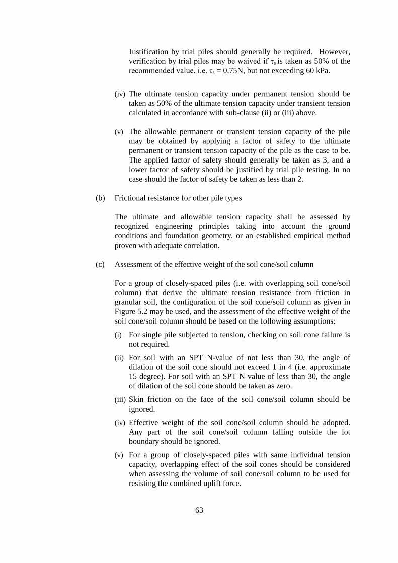
Justification by trial piles should generally be required. However, verification by trial piles may be waived if τs is taken as 50% of the recommended value, i.e. τs = 0.75N, but not exceeding 60 kPa.
(iv) The ultimate tension capacity under permanent tension should be taken as 50% of the ultimate tension capacity under transient tension calculated in accordance with sub-clause (ii) or (iii) above.
(v) The allowable permanent or transient tension capacity of the pile may be obtained by applying a factor of safety to the ultimate permanent or transient tension capacity of the pile as the case to be. The applied factor of safety should generally be taken as 3, and a lower factor of safety should be justified by trial pile testing. In no case should the factor of safety be taken as less than 2.
(b) Frictional resistance for other pile types
The ultimate and allowable tension capacity shall be assessed by recognized engineering principles taking into account the ground conditions and foundation geometry, or an established empirical method proven with adequate correlation.
(c) Assessment of the effective weight of the soil cone/soil column
For a group of closely-spaced piles (i.e. with overlapping soil cone/soil column) that derive the ultimate tension resistance from friction in granular soil, the configuration of the soil cone/soil column as given in Figure 5.2 may be used, and the assessment of the effective weight of the soil cone/soil column should be based on the following assumptions:
(i) For single pile subjected to tension, checking on soil cone failure is not required.
(ii) For soil with an SPT N-value of not less than 30, the angle of dilation of the soil cone should not exceed 1 in 4 (i.e. approximate 15 degree). For soil with an SPT N-value of less than 30, the angle of dilation of the soil cone should be taken as zero.
(iii) Skin friction on the face of the soil cone/soil column should be ignored.
(iv) Effective weight of the soil cone/soil column should be adopted. Any part of the soil cone/soil column falling outside the lot boundary should be ignored.
(v) For a group of closely-spaced piles with same individual tension capacity, overlapping effect of the soil cones should be considered when assessing the volume of soil cone/soil column to be used for resisting the combined uplift force.
63
(vi) Where the tension capacities of piles within a pile group are not the same, checking of soil cone failure of individual pile is required. The effective weight of the overlapping part of soil cones and columns between piles may be distributed to each pile on a pro rata basis according to the tension capacities of the piles.
Friction piles in soil
SPT ≥ 30
1
Soil cone
Soil column
Approx. 15o
SPT < 30
4
Pile cap
Lot boundary
Soil column/cone outside lot boundary to be ignored
Figure 5.2 Configuration of Soil Cone/Soil Column for Group of Closely-spaced Friction Piles in Soil
5.3.4 GROUND RESISTANCE FOR PILES SUBJECTED TO LATERAL LOAD
In the design of piles resisting lateral forces, consideration should be given to:
(a) the resistance of the soil or rock against lateral force, taking into account the group effect where appropriate;
(b) the structural capacity of the pile; and
(c) where pile deflection exceeds 25mm, P-∆ effect has to be addressed.
The lateral load capacity of a pile should be determined by recognized foundation engineering methods with due regard on the characteristics of surrounding soil, the characteristics of the pile or pile group, and the interaction between the surrounding soil and the pile or pile group as appropriate.
64
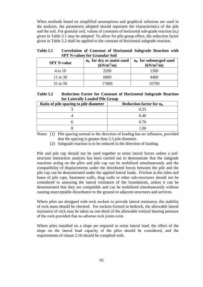
When methods based on simplified assumptions and graphical solutions are used in the analysis, the parameters adopted should represent the characteristics of the pile and the soil. For granular soil, values of constants of horizontal sub-grade reaction (nh) given in Table 5.1 may be adopted. To allow for pile group effect, the reduction factor given in Table 5.2 shall be applied to the constant of horizontal subgrade reaction.
Table 5.1 Correlation of Constant of Horizontal Subgrade Reaction with SPT N-values for Granular Soil
SPT N-value nh for dry or moist sand (kN/m2/m)
nh for submerged sand (kN/m2/m)
4 to 10 2200 1300 11 to 30 6600 4400 31 to 50 17600 10700
Table 5.2 Reduction Factor for Constant of Horizontal Subgrade Reaction for Laterally Loaded Pile Group
Ratio of pile spacing to pile diameter Reduction factor for nh
3 0.25 4 0.40 6 0.70 8 1.00
Notes: (1) Pile spacing normal to the direction of loading has no influence, provided that the spacing is greater than 2.5 pile diameter.
(2) Subgrade reaction is to be reduced in the direction of loading.
Pile and pile cap should not be used together to resist lateral forces unless a soil-structure interaction analysis has been carried out to demonstrate that the subgrade reactions acting on the piles and pile cap can be mobilized simultaneously and the compatibility of displacements under the distributed forces between the pile and the pile cap can be demonstrated under the applied lateral loads. Friction at the sides and bases of pile caps, basement walls, drag walls or other sub-structures should not be considered in assessing the lateral resistance of the foundations, unless it can be demonstrated that they are compatible and can be mobilized simultaneously without causing unacceptable disturbance to the ground or adjacent structures and services.
Where piles are designed with rock sockets to provide lateral resistance, the stability of rock mass should be checked. For sockets formed in bedrock, the allowable lateral resistance of rock may be taken as one-third of the allowable vertical bearing pressure of the rock provided that no adverse rock joints exist.
Where piles installed on a slope are required to resist lateral load, the effect of the slope on the lateral load capacity of the piles should be considered, and the requirements of clause 2.10 should be complied with.
65
5.4 COMMON PILE TYPES
This clause contains the particular requirements for some specific types of pile commonly used in Hong Kong.
5.4.1 STEEL H-PILES/STEEL TUBULAR PILES
Steel H-piles and tubular piles are usually installed by driving or pre-boring. The design of steel H-piles and tubular piles should follow the recommendations given in clauses 5.1 to 5.3.
In addition to those stated in clause 2.7, the foundation plan for such piles should also include:
(a) the physical properties and chemical composition of the piles, especially where the sectional properties are not covered by international standards;
(b) the details of pile splice and pile head;
(c) the details of protection of pile tips where hard driving is anticipated; and
(d) the orientation of steel H-piles designed to resist lateral loads.
Spliced Piles
When the piles are to be lengthened, splices can be made by welding and the following requirements should be complied with:
(a) Workmanship of welding of the splice including certification of welder test, welding procedure specification and welding procedure test should comply with acceptable standards and procedures stipulated in the Code of Practice for the Structural Use of Steel and in accordance with the supplier’s instructions and recommendations on welding consumables.
(b) Preheating to eliminate possible hydrogen-induced cracking in the welded joints should be carried out if required.
(c) A sampling rate of not less than 10% of the total number of welded joints should be tested by means of non-destructive tests prior to driving in the spliced sections of the piles. Should the test reveals any weld quality problems, thorough investigation including review on welding procedure specification should be carried out and remedial proposal should be prepared. Welder test and weld procedure test should be carried out again to confirm the effectiveness of the remedial proposal.
(d) The weld test reports, with the joint locations specified, should be included in the piling records.
(e) Test on welding should comply with the requirements given in the Code of Practice for the Structural Use of Steel unless otherwise specified in this Code of Practice.
66
5.4.2 SOCKETED STEEL H-PILES
Socketed steel H-piles are installed by inserting steel H-piles into pre-bored holes sunk into bedrock, and subsequently grouting the holes with cementitious materials.
(1) Design Principles
The following design principles should be adopted in general:
(a) The rock socket should be formed in category 1(a), 1(b) or 1(c) rock as defined in Table 2.1;
(b) The design bond strength between the rock and grout should not exceed the allowable value given in clause 2.2.2;
(c) The design bond strength between the grout and the steel H-pile should not exceed the allowable value given in clause 2.5.5(4);
(d) The grout should be non-shrink and have a minimum characteristic strength of 30 MPa at 28 days; and
(e) Rock sockets subjected to lateral load should be checked for any additional stresses induced.
(2) Construction Considerations
The following should be given due consideration when installing socketed steel H-piles:
(a) The prebored holes should be of adequate size to enable the insertion of the steel H-pile and to allow a minimum grout cover of 40 mm to the pile (except at the base);
(b) The pre-bored hole should be lined and supported by steel temporary casing to the full depth in soil at any time until concreting to prevent ground loss and soil from falling into the pre-bored hole;
(c) Overbreak or ground loss could occur if the boring operation is not properly controlled or unsuitable equipment is used. Test boring should therefore be carried out to confirm the suitability of the equipment and method, and to establish or confirm the control parameters such as the rates of penetration for different strata for the boring operation (see clause 7.4.2);
(d) The pre-bored hole should be thoroughly cleaned to remove debris and soil prior to inserting the pile into it; and
(e) See clause 5.4.1 for pile splices and clause 5.5 for pile connection to pile cap.
5.4.3 PRECAST REINFORCED CONCRETE PILES
Precast reinforced concrete piles may be used for low or medium rise buildings on ground without a significant amount of boulders or corestones.
67
In the design of precast reinforced concrete piles, stresses during lifting, transporting and driving of the pile should also be considered. Hard driving of the pile should be avoided. Special consideration should be given to the very high stresses that may occur at the head and toe of the piles.
5.4.4 PRECAST PRESTRESSED SPUN CONCRETE PILES
These piles should be driven to relatively stiff stratum with sufficient embedded length in residual soil or decomposed rock in order to develop the high bearing capacity and minimize the amount of long-term settlement. The effect of soil movement and percussion during driving on the stability of any adjacent building, structure, land, street and services should be carefully assessed.
Stringent requirements on performance test and quality control are usually required for this type of pile.
Where it is necessary to drive the pile into thick layer of stiff soil, steel conical pile shoes with cross stiffener should be used.
5.4.5 DRIVEN CAST-IN-PLACE CONCRETE PILES
Driven cast-in-place concrete pile should have a maximum size of 750 mm in diameter and is installed by driving a capped steel casing to the required level with concrete placed into the casing subsequently. Joint or splice of the steel casing should be properly designed to avoid breakage during driving. The design of the pile should be in accordance with the provision of clauses 5.1 to 5.3.
In order not to disturb the stability of the ground or the integrity of newly formed castin-place piles, driving of the piles, or any operation that may induce vibration or ground movement such as chiseling and excavation, should not be carried out within a distance less than 5-times the pile diameter from an unfilled pile excavation or a castin-place concrete pile with concrete placed in less than 24 hours.
5.4.6 SMALL DIAMETER BORED PILES
(1) General
Small diameter bored piles should have a diameter not exceeding 750 mm. They may be formed by boring casing into the ground and subsequently filling the hole with concrete/grout. The pile resistance is usually derived from shaft friction but could also be combined with end bearing in soil or rock with due consideration of strain compatibility. The design of the pile should be in accordance with the provision of clauses 5.1 to 5.3.
The contribution of friction from any fill or marine deposit layer, if exists, should usually be ignored unless it can be proved that there is no possibility of
68
future consolidation. NSF should be considered in accordance with the provision of clause 5.2.
(2) Continuous Flight Auger Pile
Continuous flight auger pile (CFA pile) is a particular type of small diameter bored pile. It is formed by drilling a hole to the required depth in soil by using a continuous flight auger. Cement grout is pumped through an orifice in the auger while the auger is withdrawn from the hole. A reinforcement cage is lowered into the grout while it is still in a fluid state.
The allowable bearing capacity of CFA pile founded on soil Rbc in kN may be determined by the following equation:
Rbc = µ Nav p L + 5 Nb Ab
where µ = friction factor Nav = average SPT N-value along pile shaft but not exceeding 40 p = perimeter of pile in m L = length of pile in m Ab = bearing area of the pile base in m2
Nb = SPT N-value at pile base but not exceeding 200
Where it is adequately justified by trial piles, the limit of the friction factor may be increased to 1.6. Where trial pile has not been carried out, 1.0 may be adopted for the friction factor.
To avoid overbreaking or ground loss resulted from ground boring, test boring should be carried out and all important parameters, such as the penetration rate and the plant operating settings, should be recorded for the use in monitoring the boring operation of the working piles.
The total grout factor, i.e. the actual grout volume divided by the theoretical grout volume, of the trial pile and the grout factor of each 1.5 m increment of the trial pile shall be recorded. These factors should then be used to check the grouting of the working piles as follows:
(a) the grout factor for each 1.5 m increment of a working pile should be not less than the smallest 1.5 m incremental grout factor obtained during the trial pile installation and in no case be less than 1.15; and
(b) the total grout factor of a working pile should be not less than that of the trial pile and in no case be less than 1.4.
Where obstruction is encountered in the top few meters of the CFA pile, it may usually be removed to allow installation of the pile to be continued at the same location. Where drilling refusal, i.e. the rate of penetration of the drilling is less than 300 mm per minute, is encountered at a greater depth of the CFA pile, the following procedures may be considered:
69
(a) If the pile is closer than 6 pile diameters from any completed CFA pile, the drilling hole should be backfilled with cement grout and the pile should be relocated;
(b) If the pile is not closer than 6 pile diameters from any completed CFA pile, the obstruction may be removed by a suitable method, and the drilling hole should be backfilled with sand before reinstalling the pile, and the required pile length should be reassessed by ignoring the contribution of shaft friction resistance from soil above the obstruction.
5.4.7 LARGE DIAMETER BORED PILES
Large diameter bored piles should be greater than 750 mm in pile shaft diameter which should be taken as the outer diameter of the temporary steel casing. It is usually installed by machine boring to the required level with concrete filling the bored hole subsequently. The boring operation should be carried out under water or in a suitable fluid such as bentonite and no dewatering for the excavation should be permitted. Steel temporary casing should be used to line and support the hole to the full depth in soil at any time during the boring operation until concreting. In firm ground, such as in completely or highly decomposed rocks, other suitable means of support such as a bentonite slurry with sufficient hydraulic head may be used to maintain the stability of the excavation.
The design of the pile should be in accordance with the provision of clauses 5.1 to 5.3. The load-carrying capacity of a large diameter bored pile is usually derived from the following means:
(a) end bearing resistance on rock at the pile base without bell-out;
(b) end bearing resistance on rock at the pile base with bell-out; or
(c) bond or frictional resistance of the pile in a rock socket.
Items (b) and (c) may be used simultaneously provided that the socket length for calculating the bond or frictional resistance does not exceed 1 times the rock socket diameter or 3 m, whichever is the shorter, and the resistance from the section of rock socket immediately above the bell-out zone and equal to 750mm is ignored.
Items (a) and (c) may be used simultaneously provided that the socket length for calculating the bond or frictional resistance does not exceed 2 times the rock socket diameter or 6 m, whichever is the shorter.
Where bell-out of the pile base is allowed, it should not exceed 1.65 times the pile shaft diameter and the gradient should not exceed 30 degree from vertical.
Where steep bedrock profile is identified, the founding levels of adjacent piles should not differ by more than the clear distance between the pile bases unless the stability of rock under the piles are checked by recognized engineering principles, taking into account the existence of any adverse joints.
70
5.4.8 MINI-PILES
(1) General
A mini-pile usually consists of a number of steel reinforcing bars encased by grout inside a drill hole. It is mainly used to resist compression or tension loads. A mini-pile shall satisfy the following requirements:
(a) not more than 5 steel bars with diameter not exceeding 50 mm;
(b) outer diameter of casing not exceeding 450 mm;
(c) pile capacity under working loads without wind not exceeding 2350 kN.
If a mini-pile cannot meet any one or more of the above requirements, it should be individually considered. Trial piles may be required to justify the performance of such pile.
(2) Design Principles
The following design principles should be adopted in general:
(a) The structural capacity of a mini-pile should be derived solely from the steel bars. Contributions from the grout and steel casing should be ignored because of the relatively high stress in the steel bars and strain incompatibility. The allowable stress of steel bars may be taken as 47.5% of the yield strength of the steel bars;
(b) Mini-piles are normally designed to be socketed into rock. The allowable bearing capacity should be derived from the bond strength between the grout and rock. The rock socket should be formed in category 1(a), 1(b) or 1(c) rock as defined in Table 2.1. The bond strength should not exceed the allowable value given in clause 2.2.2. In this connection, the steel bars should have adequate grout cover, which should not be less than 30 mm to allow effective transfer of bond stress from the reinforcing bars to the rock socket and adequate protection against corrosion;
(c) The allowable bond strength between steel bars and grout should be taken as 0.8 MPa for cement grout with a minimum characteristic compressive strength of 30 MPa at 28 days;
(d) The clear spacing between steel bars should not be less than 20mm;
(e) The perimeter of the shear plane for checking bond stress between the steel bars and grout should be taken as the smallest perimeter of the enclosing round-corner square (for 4 bars configuration) or enclosing circle (for 5 bars configuration);
(f) Where in the special circumstances that mini-piles are designed to rely on soil friction, testing on trial pile should be carried out to verify the design assumptions;
71
(g) Mini-piles should not be designed to resist lateral load by bending in view of their limited bending capacity. When lateral loads are to be resisted by the pile cap, the lateral displacement should be restricted to a magnitude which will not induce adverse effect to the strength and integrity of the pile;
(h) Where raking mini-piles are used to resist lateral forces, care should be taken to ensure equilibrium of forces and moments are maintained, taking into consideration the lack of bending stiffness of the piles and the effectively hinged conditions at the pile heads and bases;
(i) The allowable buckling capacity of the mini-piles should be checked because of their relative slenderness. Lateral restraints from the grout, permanent steel casing and the surrounding soil may be allowed in assessing the buckling capacity of the pile;
(j) Where the mini-piles are installed through weak strata or cavities or installed with sleeves, the lateral stability of the pile should be duly considered. In the absence of better criteria, weak strata may be defined as soil strata that do not have at least 5 m thick soil layer with an average SPT N-value not less than 10 and no individual SPT N-value less than 5;
(k) Raking piles should not be used in ground susceptible to consolidation settlement which may induce significant bending in the piles.
(3) Construction Considerations
The following should be given due consideration when constructing mini-piles:
(a) Steel casing should be provided to support the pre-drilled hole within the soil and/or fractured rock during drilling operation;
(b) A permanent steel casing should be provided to enhance corrosion protection. In general, a combination of minimum 5 mm thick permanent steel casing and a grout cover not less than the greater of 20 mm or the reinforcing bar diameter may be considered as adequate protection to the reinforcing bars under normal ground conditions. The steel casing may terminate with the minimum socket depth as required under clause 2.2.2 into rock of Cat 1(c) or better. However, if aggressive environment, such as fluctuation of ground water level or rock of high acid level at the socket portion is present, long-term durability shall be assessed and provision of extra cover, coating or galvanizing of the reinforcing bar may be necessary;
(c) A non-shrink cement grout with a minimum characteristic compressive strength of 30 MPa at 28 days should be used for encasing the steel bars;
72

(d) Verticality, inclination and alignment of the mini-piles should be checked during installation to verify any design assumption on eccentric moments induced in the piles;
(e) Steel couplers should generally be used for splicing of the reinforcing bars. Application of mechanical couplers should comply with the requirements given in the Code of Practice for Structural Use of Concrete and should be strictly in accordance with the manufacturer’s specifications and recommendations.
5.4.9 BARRETTES
Barrettes, or barrette piles are installed by machine excavation into a bentonite slurry filled trench down to the founding level, inserting the reinforcement cage and concreting the excavated trench by tremie method. They are usually of rectilinear sections and founded by end bearing on rock. Other founding criteria may also be used provided that their suitability is demonstrated. The design of the pile should be in accordance with the provision of clauses 5.1 to 5.3.
The bentonite slurry in the excavated trench should be of sufficient hydraulic head to maintain the stability of the trench, including any surcharge from adjacent structures and construction loads. Rigid reinforced concrete guide walls are usually provided to maintain alignment and verticality of the excavation.
5.4.10 HAND-DUG CAISSONS
Hand-dug caisson works have been banned for general use because of safety and health reasons. However foundation plans including hand-dug caisson works may still be approved when it can be demonstrated that any of the following circumstances exists:
(a) the depth of the hand-dug caissons does not exceed 3 m and the diameter of the inscribed circle of the hand-dug caissons is not less than 1.5 m;
(b) for the site concerned : (i) the use of a hand-dug caissons is the only practical construction
method; or (ii) there is no other safe engineering alternative.
5.4.11 STEEL H-PILES DRIVEN TO BEDROCK
(1) General Considerations
This clause may be used for steel H-piles driven to bedrock which is not steeper than 25 degree from the horizontal. For steeper bedrock, the case should be individually considered and more stringent requirements than those given in this clause may be required.
Where the bedrock is relatively shallow and the soil strata do not have adequate strength to allow the founding of piles, steel H-piles driven to refusal
73
with pile bases terminated on or very close to bedrock are sometimes proposed. However, this type of piles often poses the following problems:
(a) the pile bases are susceptible to damage due to hard driving at or near the bedrock;
(b) the pile bases could easily be deflected at the rock surface particularly where the bedrock profile is sloping or undulating;
(c) the piles are prone to have buckling or stability problem, as the relatively shallow and weak soil strata above bedrock may not provide adequate lateral resistance to the piles.
Where the above problems could not be satisfactorily coped with, other foundation options such as rock-socketed piles should be considered. Where the RSE has confidence in the successful installation of this type of piles, he or she may either use any recognized engineering method to cope with the above problems, or follow the guidance on design principles and construction requirements given in items (2) and (3) below.
(2) Design Principles (a) The structural design of the steel H-pile should comply with the
requirements given in clause 2.5.5(4);
(b) Piles should be founded on or close to rock not inferior to category 1(d) defined in Table 2.1. Piles may be considered as founded on rock when driven to refusal by using sufficient driving energy. Driven to refusal means the actual penetration of a pile is not more than 10mm per 10 blows and the requirements specified in item (5)(d) are complied with;
(c) The pile bases should be designed for the hard driving on or close to rock; where appropriate, the pile bases should be strengthened by suitable means such as welded-on shoes.
(d) The pile bases should be designed to avoid deflection of piles when the rock surface is encountered; where the pile is required to key into rock, the pile bases should be provided with a rock point or other suitable means;
(e) The stability of the pile foundations should be carefully assessed, particularly where the piles are short and the embedded soils are weak; in this connection, it is recommended that the piles should be designed and properly detailed as fixed head;
(f) The buckling behaviour of the piles should be checked, taking into account the lengths, any lateral load, the embedded conditions and end connections of the piles; and
(g) In the special circumstances that this type of piles are used on site with sloping or undulating rock surface, the stability of individual pile as well as the whole pile group, and that of the rock under the foundations should be assessed, taking into account the joint orientation of the rock.
74
(3) Construction Requirements (a) As an accurate estimation of the anticipated founding levels is
important to the successful installation of this type of piles, the ground investigation should provide a reasonably accurate estimation of the bedrock profile;
(b) Verticality of the steel H-piles should be checked during installation;
(c) End-bearing piles on steeply sloping rock surface should be avoided due to the possibility of sliding of pile toe on the rock surface. For bedrock not steeper than 25 degree to the horizontal, the drop height of the hammer should be reduced when the pile toe is close to the rockhead so that the pile may secure a better anchorage in the rock after the first contact. The driving may then be continued with a gradual increase in drop height until a final set of 10 mm per 10 blows is reached. Pile base strengthening and rock point may be provided. The contact of the pile toe with rock surface can be detected by monitoring the driving stress at the pile toe with dynamic load tests;
(d) The RSE must provide adequate supervision of the piling operation so that where any set reading or other sign has indicated a damage or deflection of the pile base, the pile should be abandoned and replaced; and
(e) See clause 5.4.1 for pile splices and clause 5.5 for pile connection to pile cap.
(4) Trial Piles
At least 2 number of trial piles should be required to demonstrate that this type of piles is suitable in situations such as the following:
(a) the bedrock profile is undulating or sloping at more than 15 degree from horizontal;
(b) the foundations include piles shorter than 10 m (measured from cut-off level); or
(c) the foundations include piles driven through weak strata which is defined in clause 5.4.8(2)(j).
The integrity and capacity of the trial piles should be ascertained by means of:
(a) dynamic load tests; and
(b) static load tests.
(5) Additional Testing Requirements (a) In addition to the normal testing requirements for piling works, the
testing requirements specified below are required for this type of piles.
(b) Prior to the commencement of the piling operation, the RSE should confirm the design assumptions and that this type of piles could be
75
successfully installed by test driving a sufficient number of piles, which should in no case be less than 2.
(c) Dynamic load tests should be carried out to verify the capacity of at least 10% of the working piles, half of which should be selected from the group of piles with greater depth. The peak driving stress at final set should also be measured which should not be less than 75% of the yield stress of the pile.
(d) Dynamic load tests should be carried out to verify the integrity of at least 20% of the working piles, which should not include the working piles selected for the test in item (c) above. The dynamic load test for verifying integrity may be carried out at a lower stress level but not less than 30% of the yield stress of the pile, and should be carried out on a regularly basis along the course of the pile construction period as far as possible. Should unfavourable soil condition is encountered, i.e. very weak soil on top of the bedrock, a higher percentage of dynamic load tests may be required. In the absence of better criteria, weak soil may be defined as soil that does not have at least 5 m thick soil layer with an average SPT N-value not less than 20 and no individual SPT N-value less than 10.
(e) The sampling rate for proof tests may be greater than that for normal piling works.
5.4.12 STEEL H SHEAR PILES
Steel H shear pile is a common type of shear piles that are provided to resist lateral loads only. They are not designed to resist vertical loads. As such, they are usually terminated at shallower depths than the vertical load resisting piles. The design of shear capacities of the piles should be in accordance with clause 5.3.4.
All shear piles should be adequately embedded into the pile cap to ensure the compatibility of rotation and displacement between the pile cap and the shear piles.
Where shears piles are used in combination with other types of pile foundations, due consideration on the compatibility between these different types of piles should be given.
5.5 PILE CAPS
The distribution of pile loads through the pile cap should generally be carried out by flexible cap analysis that takes into consideration the axial and bending stiffnesses of the piles and the pile cap, and the interaction effects between piles, except where the distribution of pile loads is statically determinate. The connections between pile and pile cap should then be designed accordingly, taking into consideration all the forces including any tension or bending moment that may act on the connections.
76
Mini-piles should be designed with no bending stiffness at their connections to the pile cap and the rock socket. In this connection, particular care should be taken to ensure the piles and pile cap system has sufficient stability. Reference should also be made to clause 5.4.8(2)(h).
Reinforcement design and detailing of pile caps should generally comply with the requirements given in the Code of Practice for Structural Use of Concrete. However, for pile cap not less than 800 mm thick, where there are steel H-piles extending into the pile cap, the spacing of a pair of reinforcing bars may be increased to a maximum of 400 mm provided that:
(a) each reinforcing bar is no farther than 250 mm from the next adjacent reinforcing bar; and
(b) the 400 mm spacing between the pair of reinforcing bars should be trimmed with an additional bar so that the bar spacing is reduced to not more than 200 mm. The additional bar should have 90 degree hooks at the ends which should be extended into the webs or welded to the flanges of the H section. The cross-sectional area of the additional bar should not be less than 50% of the larger size of the adjacent reinforcing bars, and should not be considered in the strength design of the pile cap.
77
6. OTHER FOUNDATION TYPES/ELEMENTS
6.1 BASEMENTS AND HOLLOW BOXES
A basement or hollow box may be used as a foundation to support the superstructures. In the design of basements or hollow boxes, the general design requirements as specified in Chapter 2 should be complied with.
The vertical resistance of ground supporting a basement or hollow box may consist of one or more of the following components:
(a) end bearing at the bases of the side-walls;
(b) end bearing at the bottom slabs; and
(c) bond or frictional resistance on the external surfaces of the side walls.
The horizontal resistance of ground provided for basements or hollow boxes may consist of one or more of the following components:
(a) passive resistance of soil;
(b) bond or frictional resistance on the external surfaces of the side walls; and
(c) bond or frictional resistance at the bases of the side walls and/or the bottom slab.
Where the vertical or horizontal resistance is derived from more than one component, it should be demonstrated that all components of the resistance can be mobilized simultaneously without causing unacceptable disturbance to the ground or adjacent structures and services.
Concrete for the side walls and base slabs of a basement or hollow box should be sufficiently watertight and not inferior to grade C35.
Stability against buoyancy should be checked in accordance with the provision of clause 2.5.4. The stability against buoyancy before the completion of the superstructure should also be checked. The worst groundwater condition and the effect of possible fluctuations in the groundwater table and of possible flooding during and after construction should be considered.
The design of the permanent structures should take into account the stresses that may have developed during the various stages of the construction sequence.
6.2 DIAPHRAGM WALLS
A diaphragm wall may be used as a temporary lateral support wall for deep excavation or the permanent wall of a basement, or it may be designed for both temporary and permanent uses. It may also be used to support vertical loads.
78
It is usually cast in-situ with tremie concrete inside a bentonite slurry trench formed by excavation with a grab or other machine. The thickness of a diaphragm wall depends on the strength requirement, but it should not be less than 600 mm thick and the length of a diaphragm wall panel may vary from 3 m to 7 m, depending on the excavation tools and subsoil conditions.
The analyses of diaphragm walls should include the followings:
(a) seepage analysis for water cut-off;
(b) lateral stability analysis including toe stability;
(c) bending moments, shear forces and deflection due to lateral loads for the proposed construction sequence;
(d) bearing capacity for vertical loads;
(e) slurry trench stability during excavation; and
(f) assessment of settlement induced on adjacent structures, services and ground during construction.
Temporary strutting may be used to reduce the bending moment, shear force or deflection of the diaphragm wall due to lateral loads. The diaphragm wall should have a sufficient toe length to provide stability or cut-off of ground water. Shear pin drilled into bedrock may be used to enhance the toe stability. Grouting may be carried out under the toe level of the wall to enhance the cut-off of ground water.
6.3 RETAINING WALLS
The design and construction of retaining walls shall comply with the requirements of the Building (Construction) Regulations.
Retaining walls may be designed in accordance with “Guide to Retaining Wall Design” (GEOGUIDE 1) published by GEO. Reinforced fill retaining walls may be designed in accordance with “Guide to Reinforced Fill Structure and Slope Design” (GEOGUIDE 6) published by GEO.
The design of retaining walls should also comply with the requirements specified in Chapter 2 where:
(a) the retaining walls are used as foundation to support a building or other structure; or
(b) the retaining walls are used to resist external surcharge loads from foundations or other structures.
79
6.4 GROUND ANCHORS
Ground anchors may be used to resist uplift forces in foundation structures. They may be prestressed or unstressed.
The use of permanent prestressed ground anchors in a project imposes a long-term monitoring commitment on the maintenance parties, which usually involves appreciable recurrent cost and, should deficiencies be revealed, remedial works may be difficult and expensive. The past records show that compliance with this criterion by the owners is not practically viable. For these reasons, permanent ground anchors requiring long-term monitoring are considered as short-lived temporary building works and should not be incorporated into a permanent building.
In exceptional circumstances where permanent ground anchors are to be used, their provision and installation should be in accordance with the requirements and procedures given in “Model Specification for Prestressed Ground Anchors” (GEOSPEC 1) published by GEO.
Monitoring of prestressed ground anchors is essential throughout their service life to ensure their continued satisfactory performance. The parties responsible for subsequent maintenance should be consulted and their agreement should be obtained before prestressed ground anchors are adopted and that they should be provided with a complete set of ‘as built’ details.
6.5 RE-USE OF EXISTING FOUNDATIONS
6.5.1 GENERAL
Existing foundations that can meet the current design and construction requirements may be reused when reliable information of the existing foundations as stipulated in clause 2.7 and as-built foundation records including certified true copies of foundation record plans and construction reports retrieved from the Buildings Department or other government departments are available.
A comprehensive testing scheme should be implemented to verify the integrity, durability, suitability of the existing foundations to be reused. There are numerous factors affecting the requirements of the testing scheme. The guidance given in clauses 6.5.2 to 6.5.5 may be used as a reference for establishing the testing scheme.
Should the testing scheme reveal any deviation from the conditions assumed in the reuse of the foundations, the foundation design should be amended accordingly, and additional foundations should be provided if necessary.
Where old and new foundations are to be used together to support a building or structure, the possible differential settlements between the old and new foundations and the preloading effect on the old foundations should be considered.
80

Adequate precautionary measures and extreme care should be taken to avoid any damage to the existing foundations to be reused during the demolition and subsequent construction works.
6.5.2 GENERAL REQUIREMENTS ON TESTING
The testing scheme should include the following investigations and testing:
(a) Additional ground investigation to assess the conditions of bearing strata, the existence of any corrosive ingredient such as chloride, sulphate or biochemicals in the ground, the tidal or ground water fluctuation that may affect the corrosion of the pile;
(b) Visual inspection of structural conditions of the existing foundations near the ground surface / cut-off level of existing piles;
(c) Load tests, core-drilling tests or any other suitable tests to confirm the load-carrying capacity, integrity and material properties of the existing foundations; and
(d) Pile head condition including any anchorage bars or starter bars at cut-off levels should be inspected, and an inspection report should be included as part of the testing scheme.
6.5.3 LARGE SIZE CONCRETE PILES
Common large size concrete piles to be reused are large diameter bored piles and hand-dug caissons. The testing scheme should include the following:
(a) Dimension measurements and setting-outs of each reuse pile;
(b) Core-drilling test on each reuse pile to verify the concrete strength, founding level and founding condition. The core-drilling test should be carried out in accordance with clause 8.5. At least 3 samples evenly distributed along the length of the concrete core should be taken for compression tests to assess the in-situ concrete strengths; and
(c) Visual inspection on the pile conditions to determine if tests on sulphate and chloride content and carbonation should be carried out or not.
6.5.4 SMALL SIZE CONCRETE PILE
Common small size concrete piles to be reused are small diameter bored piles, precast reinforced concrete piles and precast prestressed spun concrete piles. The testing scheme should include the following:
(a) Dimension measurements and setting-outs of each reuse pile;
(b) Visual inspection of pile head at the existing cut-off level of each reuse pile;
(c) Re-driving of each driven pile to set, if applicable;
(d) Dynamic load tests to verify the structural conditions and load carrying capacities of at least 20% of the reuse driven steel piles; and
81
(e) Load tests in accordance with clause 8.4 on at least 5% of the reuse piles.
6.5.5 STEEL PILES AND MINI-PILES
Common steel piles to be reused are driven steel H-pile, socketed steel H-piles and mini-piles. The testing scheme should include the following:
(a) Visual inspection of pile head at the existing cut-off level of each reuse pile;
(b) Re-driving of each driven pile to set;
(c) Dynamic load tests to verify the structural conditions and load carrying capacities of at least 20% of the reuse driven steel piles; and
(d) Load tests in accordance with clause 8.4 on at least 5% of the reuse piles.
6.5.6 CONCRETE FOOTINGS
The testing scheme should include the following:
(a) Dimension measurements and setting-outs of each reuse footing;
(b) Core-drilling tests on each reuse footing to verify the concrete strength, founding level and founding stratum condition. At least 3 samples should be taken for compression tests to assess the in-situ concrete strengths; and
(c) Visual inspection on the footing conditions to determine if tests on sulphate and chloride content and carbonation should be carried out or not.
82
7. CONSTRUCTION PRACTICE AND SITE SAFETY FOR FOUNDATION WORKS
7.1 GENERAL
Foundation works should be carried out such that:
(a) the foundation is constructed in accordance with the plans approved by the Building Authority;
(b) suitable methods and sequence are adopted so as not to render inadequate the margin of safety of, or impair the stability of, or cause damage to any building, structure, land, street or services; and
(c) adequate precautionary and protective measures are provided to assure the safety of the workers on site, all persons near the site, and adjacent buildings, structures, lands, streets and services.
7.1.1 GENERAL REQUIREMENTS
All foundation works, except where the penetration depth of the foundation element does not exceed 3 m, are specialized work in the foundation category and shall be carried out by a RSC (Foundation Works).
Foundation works should comply with:
(a) the requirements of site safety supervision as stipulated in the Code of Practice for Site Safety Supervision and Technical Memorandum for Supervision Plans; and
(b) the requirements of quality supervision (see clause 7.1.2).
7.1.2 QUALITY SUPERVISION FOR FOUNDATION WORKS
The foundations are important structural elements of a building or structure. Adequate supervision should be provided to ensure that the quality of the foundation works in respect of materials, general arrangement, installation procedures, workmanship and testing are up to the required standards and conform with all relevant provisions of this Code of Practice. Reference should be made to the relevant PNAP issued by the Building Authority for requirements of quality supervision for foundation works.
7.1.3 CONSTRUCTION MATERIALS
(1) Concrete and grout
Sampling of concrete and compression testing of concrete test cubes should be carried out in accordance with the methods specified in CS1. Testing should be carried out by a HOKLAS accredited laboratory. The test results should be
83
reported on a HOKLAS Endorsed Test Certificate. Concreting for cast-in-situ piles should be in one continuous operation.
(2) Reinforcement
Sampling and testing of steel reinforcement should be carried out in accordance with the methods specified in CS2. Testing should be carried out by a HOKLAS accredited laboratory. The test results should be reported on a HOKLAS Endorsed Test Certificate.
(3) Steel Piles
A copy of the mill certificate of the structural steel used should be submitted to Buildings Department together with a statement signed by the RSE to confirm that the requirement of chemical composition and mechanical properties appropriate to the type of steel have been complied with.
7.1.4 EXCAVATION
Foundation works often require excavation, which, even if shallow, can be dangerous if not properly designed. Adequate precautionary and protective measures should be provided to ensure that the excavation works are properly protected and the foundation works are carried out safely.
7.2 EFFECT OF FOUNDATION WORKS ON ADJACENT STRUCTURES AND LAND
7.2.1 ASSESSMENT OF THE EFFECT OF FOUNDATION WORKS
The effect of the foundation works on surrounding land, structures and services should be assessed. The assessment should include:
(a) a detailed report on the structural conditions of all nearby buildings, structures and existing services and the geotechnical condition of the nearby land likely to be affected by the foundation works within a minimum distance of 50m measured from the site boundary;
(b) estimation of the effect of the foundation works on the nearby buildings, structures, services and lands, with particular attention given to works that will induce vibration, dewatering works, and excavation and lateral support works;
(c) estimation of the response of the nearby buildings, structures, services and land to the effect of the foundation works;
(d) proposals of measures to mitigate the effect and response mentioned in items (b) and (c) above; and
(e) proposals of the preventive and precautionary measures, monitoring scheme and contingency plans to be undertaken before and during construction.
84
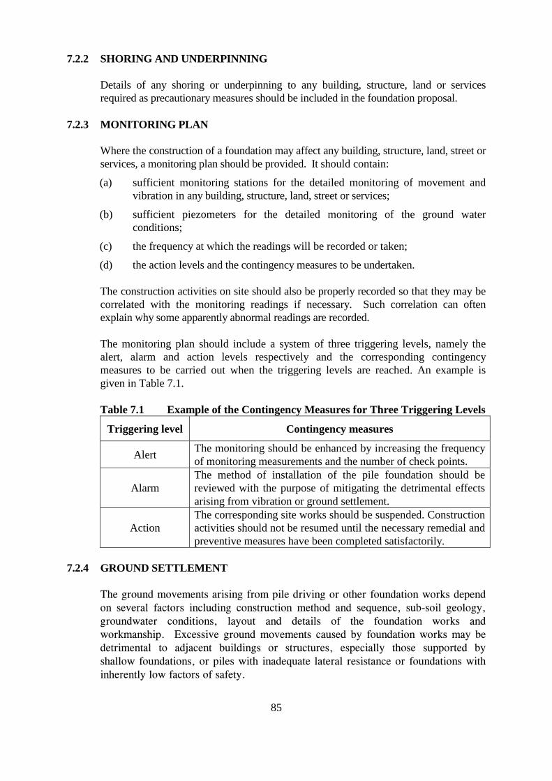
7.2.2 SHORING AND UNDERPINNING
Details of any shoring or underpinning to any building, structure, land or services required as precautionary measures should be included in the foundation proposal.
7.2.3 MONITORING PLAN
Where the construction of a foundation may affect any building, structure, land, street or services, a monitoring plan should be provided. It should contain:
(a) sufficient monitoring stations for the detailed monitoring of movement and vibration in any building, structure, land, street or services;
(b) sufficient piezometers for the detailed monitoring of the ground water conditions;
(c) the frequency at which the readings will be recorded or taken;
(d) the action levels and the contingency measures to be undertaken.
The construction activities on site should also be properly recorded so that they may be correlated with the monitoring readings if necessary. Such correlation can often explain why some apparently abnormal readings are recorded.
The monitoring plan should include a system of three triggering levels, namely the alert, alarm and action levels respectively and the corresponding contingency measures to be carried out when the triggering levels are reached. An example is given in Table 7.1.
Table 7.1 Example of the Contingency Measures for Three Triggering Levels
Triggering level Contingency measures
Alert The monitoring should be enhanced by increasing the frequency of monitoring measurements and the number of check points.
Alarm The method of installation of the pile foundation should be reviewed with the purpose of mitigating the detrimental effects arising from vibration or ground settlement.
Action The corresponding site works should be suspended. Construction activities should not be resumed until the necessary remedial and preventive measures have been completed satisfactorily.
7.2.4 GROUND SETTLEMENT
The ground movements arising from pile driving or other foundation works depend on several factors including construction method and sequence, sub-soil geology, groundwater conditions, layout and details of the foundation works and workmanship. Excessive ground movements caused by foundation works may be detrimental to adjacent buildings or structures, especially those supported by shallow foundations, or piles with inadequate lateral resistance or foundations with inherently low factors of safety.
85
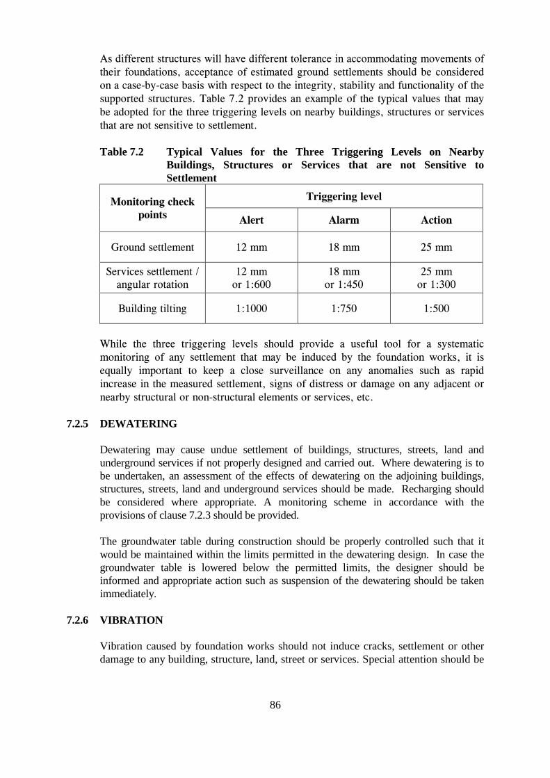
As different structures will have different tolerance in accommodating movements of their foundations, acceptance of estimated ground settlements should be considered on a case-by-case basis with respect to the integrity, stability and functionality of the supported structures. Table 7.2 provides an example of the typical values that may be adopted for the three triggering levels on nearby buildings, structures or services that are not sensitive to settlement.
Table 7.2 Typical Values for the Three Triggering Levels on Nearby Buildings, Structures or Services that are not Sensitive to Settlement
Monitoring check Triggering level
points Alert Alarm Action
Ground settlement 12 mm 18 mm 25 mm
Services settlement / angular rotation
12 mm or 1:600
18 mm or 1:450
25 mm or 1:300
Building tilting 1:1000 1:750 1:500
While the three triggering levels should provide a useful tool for a systematic monitoring of any settlement that may be induced by the foundation works, it is equally important to keep a close surveillance on any anomalies such as rapid increase in the measured settlement, signs of distress or damage on any adjacent or nearby structural or non-structural elements or services, etc.
7.2.5 DEWATERING
Dewatering may cause undue settlement of buildings, structures, streets, land and underground services if not properly designed and carried out. Where dewatering is to be undertaken, an assessment of the effects of dewatering on the adjoining buildings, structures, streets, land and underground services should be made. Recharging should be considered where appropriate. A monitoring scheme in accordance with the provisions of clause 7.2.3 should be provided.
The groundwater table during construction should be properly controlled such that it would be maintained within the limits permitted in the dewatering design. In case the groundwater table is lowered below the permitted limits, the designer should be informed and appropriate action such as suspension of the dewatering should be taken immediately.
7.2.6 VIBRATION
Vibration caused by foundation works should not induce cracks, settlement or other damage to any building, structure, land, street or services. Special attention should be
86
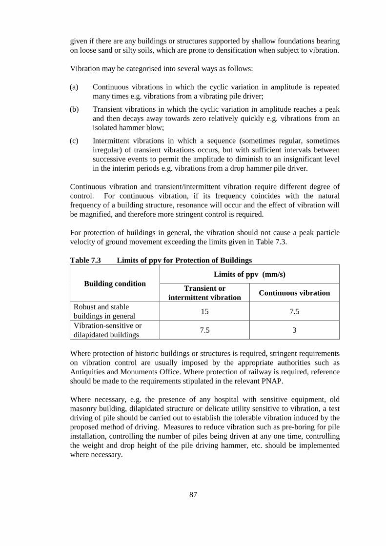
given if there are any buildings or structures supported by shallow foundations bearing on loose sand or silty soils, which are prone to densification when subject to vibration.
Vibration may be categorised into several ways as follows:
(a) Continuous vibrations in which the cyclic variation in amplitude is repeated many times e.g. vibrations from a vibrating pile driver;
(b) Transient vibrations in which the cyclic variation in amplitude reaches a peak and then decays away towards zero relatively quickly e.g. vibrations from an isolated hammer blow;
(c) Intermittent vibrations in which a sequence (sometimes regular, sometimes irregular) of transient vibrations occurs, but with sufficient intervals between successive events to permit the amplitude to diminish to an insignificant level in the interim periods e.g. vibrations from a drop hammer pile driver.
Continuous vibration and transient/intermittent vibration require different degree of control. For continuous vibration, if its frequency coincides with the natural frequency of a building structure, resonance will occur and the effect of vibration will be magnified, and therefore more stringent control is required.
For protection of buildings in general, the vibration should not cause a peak particle velocity of ground movement exceeding the limits given in Table 7.3.
Table 7.3 Limits of ppv for Protection of Buildings
Building condition Limits of ppv (mm/s)
Transient or intermittent vibration Continuous vibration
Robust and stable buildings in general 15 7.5
Vibration-sensitive or dilapidated buildings 7.5 3
Where protection of historic buildings or structures is required, stringent requirements on vibration control are usually imposed by the appropriate authorities such as Antiquities and Monuments Office. Where protection of railway is required, reference should be made to the requirements stipulated in the relevant PNAP.
Where necessary, e.g. the presence of any hospital with sensitive equipment, old masonry building, dilapidated structure or delicate utility sensitive to vibration, a test driving of pile should be carried out to establish the tolerable vibration induced by the proposed method of driving. Measures to reduce vibration such as pre-boring for pile installation, controlling the number of piles being driven at any one time, controlling the weight and drop height of the pile driving hammer, etc. should be implemented where necessary.
87
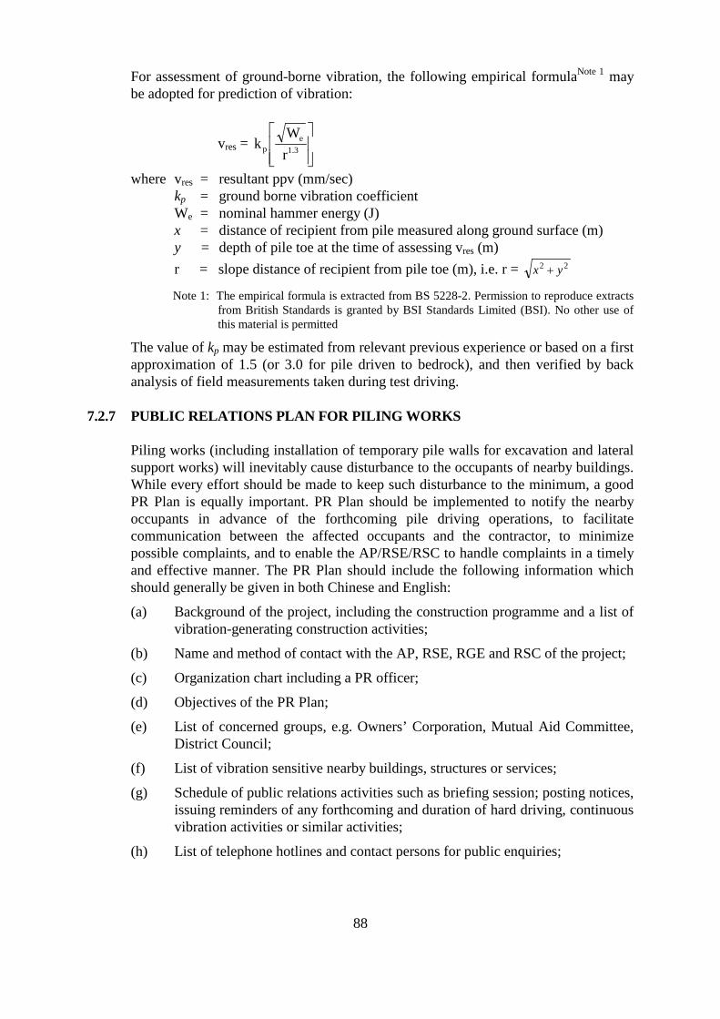
For assessment of ground-borne vibration, the following empirical formulaNote 1 may be adopted for prediction of vibration:
We
vres = kp r1.3
where vres = resultant ppv (mm/sec)
kp = ground borne vibration coefficient We = nominal hammer energy (J) x = distance of recipient from pile measured along ground surface (m) y = depth of pile toe at the time of assessing vres (m) r = slope distance of recipient from pile toe (m), i.e. r = x2 +y2
Note 1: The empirical formula is extracted from BS 5228-2. Permission to reproduce extracts from British Standards is granted by BSI Standards Limited (BSI). No other use of this material is permitted
The value of kp may be estimated from relevant previous experience or based on a first approximation of 1.5 (or 3.0 for pile driven to bedrock), and then verified by back analysis of field measurements taken during test driving.
7.2.7 PUBLIC RELATIONS PLAN FOR PILING WORKS
Piling works (including installation of temporary pile walls for excavation and lateral support works) will inevitably cause disturbance to the occupants of nearby buildings. While every effort should be made to keep such disturbance to the minimum, a good PR Plan is equally important. PR Plan should be implemented to notify the nearby occupants in advance of the forthcoming pile driving operations, to facilitate communication between the affected occupants and the contractor, to minimize possible complaints, and to enable the AP/RSE/RSC to handle complaints in a timely and effective manner. The PR Plan should include the following information which should generally be given in both Chinese and English:
(a) Background of the project, including the construction programme and a list of vibration-generating construction activities;
(b) Name and method of contact with the AP, RSE, RGE and RSC of the project;
(c) Organization chart including a PR officer;
(d) Objectives of the PR Plan;
(e) List of concerned groups, e.g. Owners’ Corporation, Mutual Aid Committee, District Council;
(f) List of vibration sensitive nearby buildings, structures or services;
(g) Schedule of public relations activities such as briefing session; posting notices, issuing reminders of any forthcoming and duration of hard driving, continuous vibration activities or similar activities;
(h) List of telephone hotlines and contact persons for public enquiries;
88
(i) Details of the complaint handling mechanism, including any pledges on response time, follow-up reply to complainant after the course of the complaint has been dealt with, etc.;
(j) Details of the vibration and settlement monitoring plan, including frequency for taking measurements, the threshold limits for the measurements, etc.;
(k) Flow chart for public relations action plan;
(l) Proforma for recording complaint, including complainant details, causes of complaint, remedial actions and follow-up reply to complainant; and
(m) Register of number of complaints received.
7.2.8 BLASTING
If blasting is to be carried out as part of the foundation works, it must be properly designed and controlled such that it will not adversely affect the stability of any adjacent slope, retaining wall, building, structures and services through ground vibrations or other effects. Adequate measures must also be provided to protect the safety of the workers and the public against possible flyrock.
When blasting is to be adopted for foundation works, reference should be made to the following:
(a) Regulation 23 of the Building (Construction) Regulations;
(b) Regulation 46 of the Dangerous Goods (General) Regulations;
(c) PNAP APP-24 - Railway Protection
(d) PNAP APP-72 - Control of Blasting; and
(e) General Specification for Civil Engineering Works.
7.3 FOUNDATION RECORDS AND REPORTS
The Building Authority requires the submission of record plans, report and a specified form certifying the completion of the foundation works by the relevant personnel upon completion of the works.
Foundation Record Plans
Record plans should include details of the characteristic features of the site and the identification, location, size, depth and level of each foundation unit as constructed.
Foundation Report
The report should include:
(a) the date of construction/installation, the quality and quantity of materials used and any necessary test on the bearing strata for each foundation unit;
89
(b) the driving performance and verification of the design assumption made on vibration predication for driven piles;
(c) the concrete test cube results, excavation records, predrilling and post-installation proof drilling records for bored piles; and
(d) a review on the following items should be carried out to identify any rooms for improvement: (i) the scope of the condition survey on nearby buildings; (ii) the effectiveness of the monitoring plan; and (iii) the effectiveness of the PR Plan.
7.4 PILE CONSTRUCTION
7.4.1 DRIVING TEST AND TRIAL PILES
For driven piles, test driving should be conducted to verify the design assumptions made for the piles and founding strata prior to driving any other piles.
Where special ground conditions exist or when a new type of piles is to be used, trial piles may be required to be carried out before the installation of other working piles in order to verify the design assumptions and the performance of the pile. The trial piles should also be tested by the imposition of test loads in accordance with the procedures and criteria specified in clause 8.4 upon installation.
7.4.2 TEST BORING
Where boring is carried out with the drilling bit that advances ahead of the steel casing and the drill hole is larger than 450 mm, the following problems may occur:
(a) overbreak/ground loss resulting in undue disturbance to sub-soil – usually due to the presence of problematic soil layers such as bouldery reclamation fill, improper operation of the boring equipment, or the use of ineffective or worn-out drilling bits; and
(b) excessive drawdown of water table – usually due to adverse geology in the soil/rock strata such as the presence of permeable rock joints.
Therefore, test boring is required to assess the following:
(a) the safety and suitability of the boring method and equipment;
(b) the drawdown of ground water table and ground settlements that may be induced by the boring operation for reviewing the proposed monitoring plan; and
(c) the range of anticipated rates of advancement of the boring operation for different soil or rock strata for control of the boring operation for working piles.
The following should be specified in the test boring proposal:
90
(a) details of the boring machine to be used on site, including the complete operating mechanism of the drill bit;
(b) the maximum volume of air supply and pressure to be applied in different soil and rock strata;
(c) the minimum rate of advancement of the drill bit;
(d) piles selected for test boring;
(e) additional ground and piezometer monitoring arrangement (including details, locations and monitoring frequencies of check points) for the test boring works;
(f) criteria for satisfactory performance of the boring operation based on the ground and piezometer monitoring results; and
(g) procedures for monitoring the rates advancement of the boring operation for different soil and grade of rock strata.
7.4.3 PRE-DRILLING
For piles founded on rock or rock socket, sufficient pre-drilling should be carried out to identify the depth and quality of the founding rock. Such pre-drilling should be sunk at least 5 m into the category of rock specified for founding or forming of rock socket, or the designed rock socket length of the pile, whichever is the deeper.
For large diameter bored piles, barrettes and the like, pre-drilling should be carried out for each pile.
For mini-piles, socketed steel H-piles, steel H-piles driven to bedrock and similar small diameter bored piles founding on rock or rock socket, pre-drilling should be carried out such that the tip of every pile should be within 5 m distance from a predrilling hole. The pre-drilling should be sunk at least 5 m into the category of rock specified for founding or forming of rock socket, or the designed rock socket length of the nearest pile, whichever is the deeper.
7.4.4 POST CONSTRUCTION PROOF DRILLING
Large Diameter Bored Piles, Barrettes and the Like
To ascertain the soundness of the interface, core-drilling should be carried out at the concrete/rock interface for each of the large diameter bored piles, barrettes and the like. The core-drilling should cover at least 1 m above and below the interface.
Socketed H-piles, H-piles driven to bedrock and Mini-piles
To verify the quality of rock for founding or forming of rock socket, additional proof drill holes should be sunk at least 5 m below the as-built top level of the rock socket, or the as-built rock socket length of the nearest pile, whichever is the deeper. The recommended number of such drill holes should be at least 2 for sites with 100 or less piles; or 1% of the number of piles for sites with more than 100 piles (any fraction of a drill hole so calculated should be construed as one additional drill hole). An
91
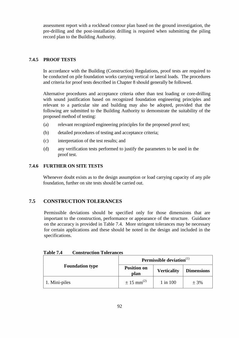
assessment report with a rockhead contour plan based on the ground investigation, the pre-drilling and the post-installation drilling is required when submitting the piling record plan to the Building Authority.
7.4.5 PROOF TESTS
In accordance with the Building (Construction) Regulations, proof tests are required to be conducted on pile foundation works carrying vertical or lateral loads. The procedures and criteria for proof tests described in Chapter 8 should generally be followed.
Alternative procedures and acceptance criteria other than test loading or core-drilling with sound justification based on recognized foundation engineering principles and relevant to a particular site and building may also be adopted, provided that the following are submitted to the Building Authority to demonstrate the suitability of the proposed method of testing:
(a) relevant recognized engineering principles for the proposed proof test;
(b) detailed procedures of testing and acceptance criteria;
(c) interpretation of the test results; and
(d) any verification tests performed to justify the parameters to be used in the proof test.
7.4.6 FURTHER ON SITE TESTS
Whenever doubt exists as to the design assumption or load carrying capacity of any pile foundation, further on site tests should be carried out.
7.5 CONSTRUCTION TOLERANCES
Permissible deviations should be specified only for those dimensions that are important to the construction, performance or appearance of the structure. Guidance on the accuracy is provided in Table 7.4. More stringent tolerances may be necessary for certain applications and these should be noted in the design and included in the specifications.
Table 7.4 Construction Tolerances
Foundation type Permissible deviation(1)
Position on plan Verticality Dimensions
1. Mini-piles ± 15 mm(2) 1 in 100 ± 3%
92
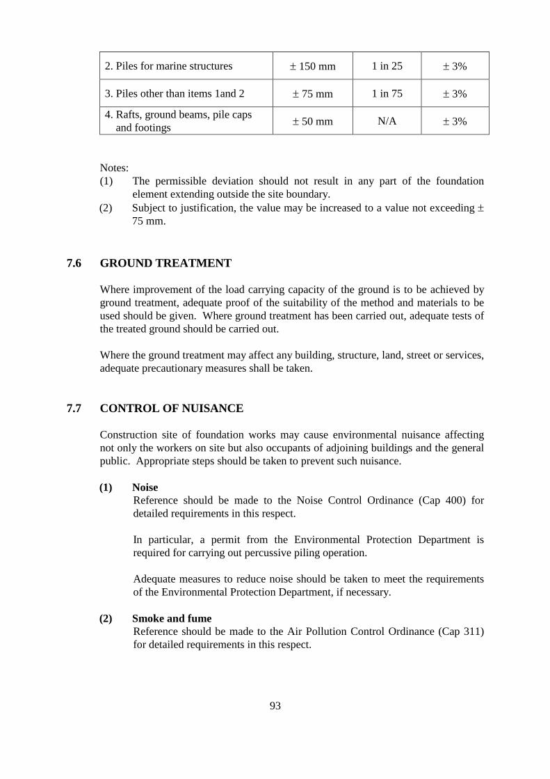
2. Piles for marine structures ± 150 mm 1 in 25 ± 3%
3. Piles other than items 1and 2 ± 75 mm 1 in 75 ± 3%
4. Rafts, ground beams, pile caps and footings ± 50 mm N/A ± 3%
Notes: (1) The permissible deviation should not result in any part of the foundation
element extending outside the site boundary. (2) Subject to justification, the value may be increased to a value not exceeding ±
75 mm.
7.6 GROUND TREATMENT
Where improvement of the load carrying capacity of the ground is to be achieved by ground treatment, adequate proof of the suitability of the method and materials to be used should be given. Where ground treatment has been carried out, adequate tests of the treated ground should be carried out.
Where the ground treatment may affect any building, structure, land, street or services, adequate precautionary measures shall be taken.
7.7 CONTROL OF NUISANCE
Construction site of foundation works may cause environmental nuisance affecting not only the workers on site but also occupants of adjoining buildings and the general public. Appropriate steps should be taken to prevent such nuisance.
(1) Noise Reference should be made to the Noise Control Ordinance (Cap 400) for detailed requirements in this respect.
In particular, a permit from the Environmental Protection Department is required for carrying out percussive piling operation.
Adequate measures to reduce noise should be taken to meet the requirements of the Environmental Protection Department, if necessary.
(2) Smoke and fume Reference should be made to the Air Pollution Control Ordinance (Cap 311) for detailed requirements in this respect.
93
Emission of excessive black smoke or fume from diesel hammer is actionable under the Air Pollution Control Ordinance (Cap 311) which is enforced by Environmental Protection Department.
(3) Waste water and chemical waste Reference should be made to the Public Health and Municipal Services Ordinance (Cap 132) for detailed requirements in this respect.
In particular, muddy water or chemical waste from a construction site should not be discharged into the drainage system. Any contractor acting against this will be required by the Drainage Services Department to indemnify the Government against costs due to such act.
(4) Vibration In addition to the provision of clause 7.2.6, vibration should not create unacceptable discomfort to the occupants of nearby buildings.
7.8 FOUNDATION WORKS IN SCHEDULED AREAS
7.8.1 GENERAL
For foundation works in the Scheduled Areas, there are usually special requirements imposed by the Building Authority. These may include settlement monitoring, control on vibration and performance review of the foundation works. Before commencement of the works, reference should be made to the relevant PNAP issued by the Building Authority.
7.8.2 PERFORMANCE REVIEW AND SETTLEMENT MONITORING FOR SCHEDULED AREA NOS. 2 AND 4
Performance reviews in Scheduled Area Nos. 2 and 4, when required, usually include a review of the ground conditions encountered during pile driving, pile installation or foundation construction, and an assessment of the effects of pile driving on the surroundings and construction records. It should also contain the results and an assessment of the pile load tests. The review should demonstrate that the foundation works have been adequately inspected and the construction records adequately assessed in the course of construction and that any necessary changes in the design have been undertaken and the foundation plans have been suitably amended and approved.
For buildings founded on marble, settlement monitoring using precise levelling or other approved methods should be arranged. The monitoring should commence as soon as possible after the completion of foundation works and should be continued until the issue of occupation permit. Readings should be taken at intervals sufficiently close to minimize scatter, with a frequency not less than monthly. The monitoring should be carried out by a qualified land surveyor.
94
8. TESTING OF FOUNDATIONS AND GROUND
8.1 GENERAL
Testing of foundations may be required for one or more of the following purposes:
(a) to ascertain the performance of the foundation under load;
(b) to establish or justify the design parameters; and
(c) to verify the structural integrity of the foundation units.
The type of test selected and the number of tests required should be appropriate to the type of foundation and suitable for the purpose required.
Except standard penetration tests (see clause 8.3) and proof test by core-drilling (see clause 8.5), all tests specified in this Chapter should be carried out by a HOKLAS accredited laboratory.
8.2 PLATE LOAD TEST
(1) General
Plate load test may be used to verify:
(a) the allowable bearing capacity ; and
(b) by means of back-analysis, the value of Young’s modulus of soils adopted in the settlement calculations.
However, the results of the test may not be able to reflect the behaviour of all soil strata affected by the footing. In addition, any extrapolation of the test results to a footing larger than the test plate must be carried out with caution, in particular, for non-homogeneous ground conditions.
The plate load test should be carried out at the founding level or a level that can reflect the groundwater condition and the behaviour of soil strata affected by the foundation.
(2) Test Procedures and Acceptance Criteria
Any suitable test procedures and acceptance criteria with full justification may be used. The following may be considered as suitable test procedures and acceptance criteria for plate load tests on cohesionless soils:
(a) The loading plate should not be less than 300 mm, square or circular.
(b) The test load adopted should not be less than 3Wt, so that the significant stress on soil and settlement can be obtained. Wt is the test load obtained as follows:
95
(c)
(d)
(e)
(f)
(g)
(h)
(q )u plate Wt = × Aplate 3
where (qu)plate is the ultimate bearing capacity of the test plate based on the design bearing capacity factors Nc and Nγ (see clause 2.2.4); and
Aplate is the area of the test plate.
For cohesionless soils,
Wt = 0.1 γ B3 Nγ for square test plate = 0.025 p γ B3 Nγ for circular plate
where γ is the bulk unit weight of soil at test location; B is the width or diameter of test plate.
An initial load not exceeding 25% of the initial overburden pressure may be applied to the test plate to reduce the bedding error before conducting the plate loading test.
The test load should be applied in increments of 0.5Wt up to Wt, released and reapplied in increments of 0.5Wt up to 2Wt, then released and reapplied in increment of 0.5Wt up to 3Wt, which should be maintained for at least 72 hours before removal.
The load at each incremental stage should be held for a period of 10 minutes or longer until the rate of settlement is less than 0.05 mm in 10 minutes.
If the maximum settlement of the plate Smax does not exceed 0.15B, then the allowable bearing capacity is considered satisfactory.
The Young’s modulus, Es, of the soil for settlement calculations should be obtained from the following equations:
2Wt (1− ν )Es = for square test plate
1.13SB W (1- ν2 )= t for circular plate
S B
where S is the settlement of the test plate measured at test load Wt; ν is the Poisson’s ratio (see clause 2.3.1).
The Es obtained in item (g) should be verified against the design values used in the settlement calculations.
96
8.3 STANDARD PENETRATION TEST
SPT is commonly carried out to assess the degree of compactness and consistency of granular soils. In general, the N values refer to the uncorrected N values before carrying out the foundation works. The use of SPT results for cohesive soils, such as marine deposits, alluvial deposits, etc. should be treated with extreme caution. Details of the equipment and procedures for carrying out the tests are given in GEOGUIDE 2.
8.4 COMPRESSION LOADING TEST
Imposition of test loads to a pile is considered to be most realistic in reflecting the performance of the pile and is widely used for driven piles, small diameter bored piles, socketed piles and mini-piles.
When carrying out loading tests:
(a) The pile should be load tested at the cut-off level with no allowance for group effect;
(b) The test load should be applied in 2 equal increments up to the design pile capacity under working load, then released and reapplied in 4 equal increments up to twice the design pile capacity under working load and maintained for at least 72 hours before removal;
(c) The load at each incremental stage should be held for a period of 10 minutes or longer until the rate of settlement is less than 0.05 mm in 10 minutes;
(d) The test load should be measured by a calibrated load measuring device and also by a calibrated pressure gauge in the hydraulic system;
(e) For piles resisting axial load with a diameter or least lateral dimension not exceeding 750 mm, the test is deemed to be unsatisfactory if any of the following conditions apply :
(i) the maximum settlement at the head of the pile during the test exceeds the value
2WL D + + 4mm ,
AE 120
where W is the design pile capacity under working load in kN;
L is the length of the pile in mm (For piles with rock sockets, L should be measured to the centre of the rock socket. For piles without rock sockets, L may generally be measured to the pile toe;
A is the cross-section area of the pile in mm2; E is the Young's modulus for the material of the pile
in kN/mm2; and D is the least lateral dimension of the pile in mm;
97
(ii) when the rate of recovery after the removal of the maximum test load is less than 0.1 mm/hour observed in a period of not less than 15 minutes, the residual settlement at the head of the pile exceeds the greater of the following :
D/120 + 4 mm; and 25% of the maximum pile head settlement during the test;
(f) In calculating the elastic compression/extension of the test pile, the following should be considered:
(i) for mini-piles, the contribution from steel bars, cement grout and steel casing along the whole length L; and
(ii) for socketed steel H-piles, the contribution from cement grout within the length of the rock socket; and
(g) For large diameter bored piles, barrette piles and hand-dug caissons, other suitable acceptance criteria for the loading test with full justification may be used.
8.5 CORE-DRILLING TEST
Proof core-drilling test is commonly used in large diameter bored piles, barrettes and the like which can reveal the soundness of the founding rock, concrete and the interface between the pile and the rock. When carrying out core-drilling tests:
(a) the core-drilling should be taken through the full depth of the pile and carried down to a distance of at least half a diameter of the pile base, or 600 mm, whichever is larger, into the ground upon which the pile is founded;
(b) the completed core so taken should be properly marked and arranged in proper order for inspection;
(c) the concrete cores should not show evidence of honeycombing or segregation of individual constituent materials;
(d) any rock core obtained should be visually examined to conform with the required rock material specified in the design;
(e) the cores should also be examined to confirm the adequacy of the interface between the concrete and rock; and
(f) where piles are founded on soil, standard penetration tests should be carried out at a maximum interval of 1.5 m from the pile founding level down to a distance of at least 3 times the diameter of the pile base, or 5 m, whichever is larger, to verify the required soil strength.
98
8.6 SONIC LOGGING
Sonic logging is one of the most commonly used non-destructive pile integrity tests for cast-in-place concrete piles, diaphragm walls and barrettes. It is based on the measurement of the propagation time of a sonic transmission between two piezoelectric probes placed in tubes cast into the pile.
It may be used to check the homogeneity of the concrete and to detect defects such as honeycombing, segregation, necking, inclusions and cracks in concrete.
The test should not be used beyond its limitations which include the following:
(a) it cannot identify the nature of the defects;
(b) it may affect concreting or cause defects in the pile due to the cast-in tubes for the test; and
(c) poor bonding between the tubes and concrete may result in anomalous response.
8.7 SONIC ECHO TEST
This is a rapid test carried out at the pile top. A sonic wave is generated at the pile head, e.g. by striking the pile head with a hand-held hammer. The wave travels down the pile and is reflected back up the pile from the pile toe. Any defect in the length of the pile may cause intermediate echo being recorded. With an assumed propagation velocity for the sonic wave, the length of the pile and the location of the defect can be determined.
The test may be used for checking the continuity of concrete and steel bearing piles.
The test should be carried out at least 7 days after casting of concrete so that accurate propagation velocity can be applied.
The test should not be used beyond its limitations which include the following:
(a) it is not suitable for piles with joints;
(b) it is sensitive to small bulbs or necks in the pile;
(c) the length to diameter ratio of the pile should not exceed 30 for accurate measurement;
(d) ground vibration due to other construction operation could affect the signals;
(e) response can be highly distorted for anomalies near the pile head; and
(f) diagonal cracks or change in concrete quality may not be easily identified from the test results.
99

8.8 VIBRATION TEST
This is also a rapid test carried out at the pile top. A force of constant amplitude over a broad frequency band, preferably from 0 to 5000 Hz, is applied, and the velocity in relation to this applied force is measured simultaneously, at the pile head. The applied force may be generated from an electro-dynamic vibrator or a small hand-held hammer fitted with an internal load cell. The velocity at the pile head is measured with a vibration transducer. The mechanical impedance or admittance of the pile, which is obtained by dividing the measured pile head velocity by the applied force, is plotted against the vibration frequency to form the vibration excitation and response curve for determination of the pile characteristics such as pile head stiffness, condition of anchorage at pile toe, resonating length, characteristic mobility and damping factor. Interpretation of the test results and the pile characteristics may identify whether the pile integrity is regular, or defects such as irregularity in pile section, grade of concrete and pile anchorage condition may exist.
The test should not be used beyond its limitations which include the following:
(a) the signal is easily damped for pile with a length to diameter ratio of about 20 in stiff and dense soil and 30 in loose soil;
(b) it will not identify small but structurally significant variations in the wave velocity through weak concrete zone;
(c) it is sensitive to abrupt changes, but not gradual changes, in pile cross section;
(d) it is unable to quantify the vertical extent of section changes or the lateral position of defects; and
(e) vertical cracks cannot be detected.
8.9 DYNAMIC LOAD TEST FOR DRIVEN PILES
The dynamic load test, which measures the dynamic response at the pile top resulting from the impact of a driving hammer, can be used to estimate pile capacity, monitor hammer performance, energy transfer at impact and pile-driving stresses, and detect any defect in the pile. The pile capacity can be estimated from the data of the dynamic load test by appropriate methods based on wave propagation theory. Methods such as those with oversimplified assumptions and parameters used for the analysis may not be considered as appropriate methods.
Dynamic load test reveals the mobilized pile capacity at the time of testing. A hammer with a capacity large enough to cause sufficient pile movement such that the resistance of the pile can be fully mobilized should be used to generate a stress wave. A minimum pile penetration of about 2 to 3 mm per blow should be achieved where practicable, particularly if it is required to predict the pile capacity.
In view of the limited studies and results on correlation between dynamic load test and static load test in Hong Kong, dynamic load test has not been generally accepted as
100
proof test for foundations under normal circumstances. It may however be used for the following purposes:
(a) to detect pile defects;
(b) to identify defective piles within a large group of piles;
(c) to differentiate piles with lower pile capacities within a large group of piles;
(d) to monitor the driving resistance and driving stresses in the pile; and
(e) to check the consistency of hammer efficiency.
The test should not be used beyond its limitations which include the following:
(a) the accuracy of estimation of pile capacity depends on the proper selection of soil parameters such as damping factor; and
(b) only major pile defects can be identified as small cracks tend to close up during driving.
8.10 TENSION LOADING TEST
If reaction piles are used for tension test, to minimize interaction effects, the reaction piles should be located as far from the test pile as practicable. The reaction pile should be at least 3 test pile diameters, or 2 m, whichever is larger, from the test pile, measured centre to centre. Where the spacing is less than this, corrections for possible pile interaction should be made. The test may follow the following procedures:
(a) The pile should be load tested at the cut-off level with no allowance for group effect;
(b) The test load should be applied in 2 equal increments up to the design pile capacity under working load, then released and reapplied in 4 equal increments up to twice the design pile capacity under working load and maintained for at least 72 hours before removal;
(c) The load at each incremental stage should be held for a period of 10 minutes or longer until the rate of extension is less than 0.05 mm in 10 minutes; and
(d) The test load should be measured by a calibrated load measuring device and also by a calibrated pressure gauge in the hydraulic system.
The test should be deemed to be unsatisfactory if any one of the following conditions applies:
(a) the maximum extension at the head of the pile during the test exceeds the elastic extension plus 4 mm;
(b) when the rate of recovery after the removal of the maximum test load is less than 0.1 mm/hour observed in a period of not less than 15 minutes, the residual extension at the head of the pile exceeds the greater of 4 mm and 25% of the maximum pile head extension during the test; or
(c) there is structural failure in the test pile.
101
In calculating the elastic axial extension of mini-pile or socketed steel H-pile, the following criteria should be adopted:
(a) the contribution from cement grout should be ignored; and
(b) the contribution from steel casing if used should be considered.
The maximum test load should not result in the test pile or anchor being stressed beyond the yield stress. Where the design uplift capacity of the test pile is based on bond and tensile stresses which are taken as 50% of the corresponding values in compression, the test load may be 1.5 times the design uplift capacity of the pile under working load.
Apart from reaction piles, reaction pad may be used as a reaction. The reaction pads should be of sufficient plan dimensions to transfer the reaction loads to the ground without settling at a rate that would cause difficulty in maintaining the applied test loads and the ground should be adequately strong. The reaction pads should be located as far from the test pile as possible and interaction effects should be assessed.
8.11 LATERAL LOAD TEST
Lateral load test of piles may be carried out by:
(a) jacking between two piles; or
(b) jacking a test pile against a suitable structure that could provide the reaction for the jacking force.
In the first method, both piles can be considered as test piles. It may be necessary to demonstrate that the spacing of the piles is adequate. In the second method, the suitable structure may be a temporary ‘deadman’ or weighted platform formed for the test.
Lateral load tests are usually carried out for the purpose of verifying the design parameters and method. In such case, accurate information of the strata along the full depth of the pile is required and analysis should be carried out prior to testing to predict the behaviour of the pile under the test load. The performance of the pile on site should be measured and compared with the predicted behaviour.
The test should be carried out at the cut-off level of piles and may follow the procedures in Table 8.1 When carrying out lateral load tests, measurements should be taken to record the lateral displacement at the pile heads of the test piles.
102
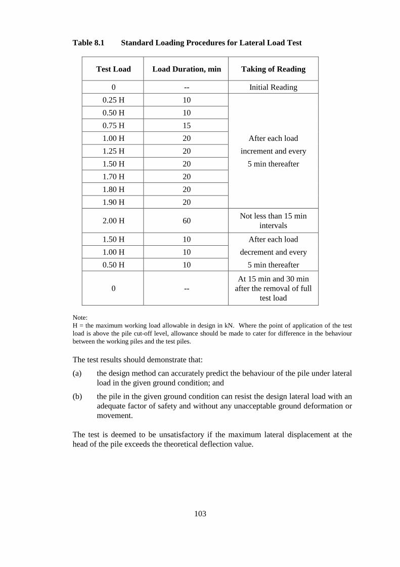
Table 8.1 Standard Loading Procedures for Lateral Load Test
Test Load Load Duration, min Taking of Reading
0 - Initial Reading 0.25 H 10
After each load increment and every
5 min thereafter
0.50 H 10 0.75 H 15 1.00 H 20 1.25 H 20 1.50 H 20 1.70 H 20 1.80 H 20 1.90 H 20
2.00 H 60 Not less than 15 min intervals
1.50 H 10 After each load decrement and every
5 min thereafter 1.00 H 10 0.50 H 10
0 -At 15 min and 30 min
after the removal of full test load
Note: H = the maximum working load allowable in design in kN. Where the point of application of the test load is above the pile cut-off level, allowance should be made to cater for difference in the behaviour between the working piles and the test piles.
The test results should demonstrate that:
(a) the design method can accurately predict the behaviour of the pile under lateral load in the given ground condition; and
(b) the pile in the given ground condition can resist the design lateral load with an adequate factor of safety and without any unacceptable ground deformation or movement.
The test is deemed to be unsatisfactory if the maximum lateral displacement at the head of the pile exceeds the theoretical deflection value.
103
8.12 ULTRASONIC ECHO SOUNDER TEST
The ultrasonic echo sounder test may be used to measure the profile of the excavation for a pile shaft, such as the dimensions of bell-outs of bored piles. It is also used to check verticality of excavation where accurate construction is required.
The equipment consists of a sensor, a winch and a recorder. In the test, the sensor is lowered into the excavation to measure the distance between the four faces of the sensor and the wall of the excavation. The sensor is prevented from twisting when it is lowered into the excavation, usually by means of guide wires. The recorder will then produce a graphical record of the measured distances against depth.
The sensor measures distances by emitting an ultrasonic pulse, and measuring the time taken for an echo to return to the sensor. The velocity of the pulse is dependent on the density of the fluid used in the excavation. In-situ calibration of the senor under the excavation fluid is normally required. Bubbles and sediment suspended in the excavation fluid can affect the accuracy of the measurement. Therefore, the excavation fluid should be left to stand after excavation to allow bubbles entrained in the fluid to dissipate and any suspended sediment to settle.
The equipment should not be used beyond its limitations, such as the dimensions that it can measure, the range of density of the excavation fluid that it may be used.
104