Embed Size (px)
Citation preview
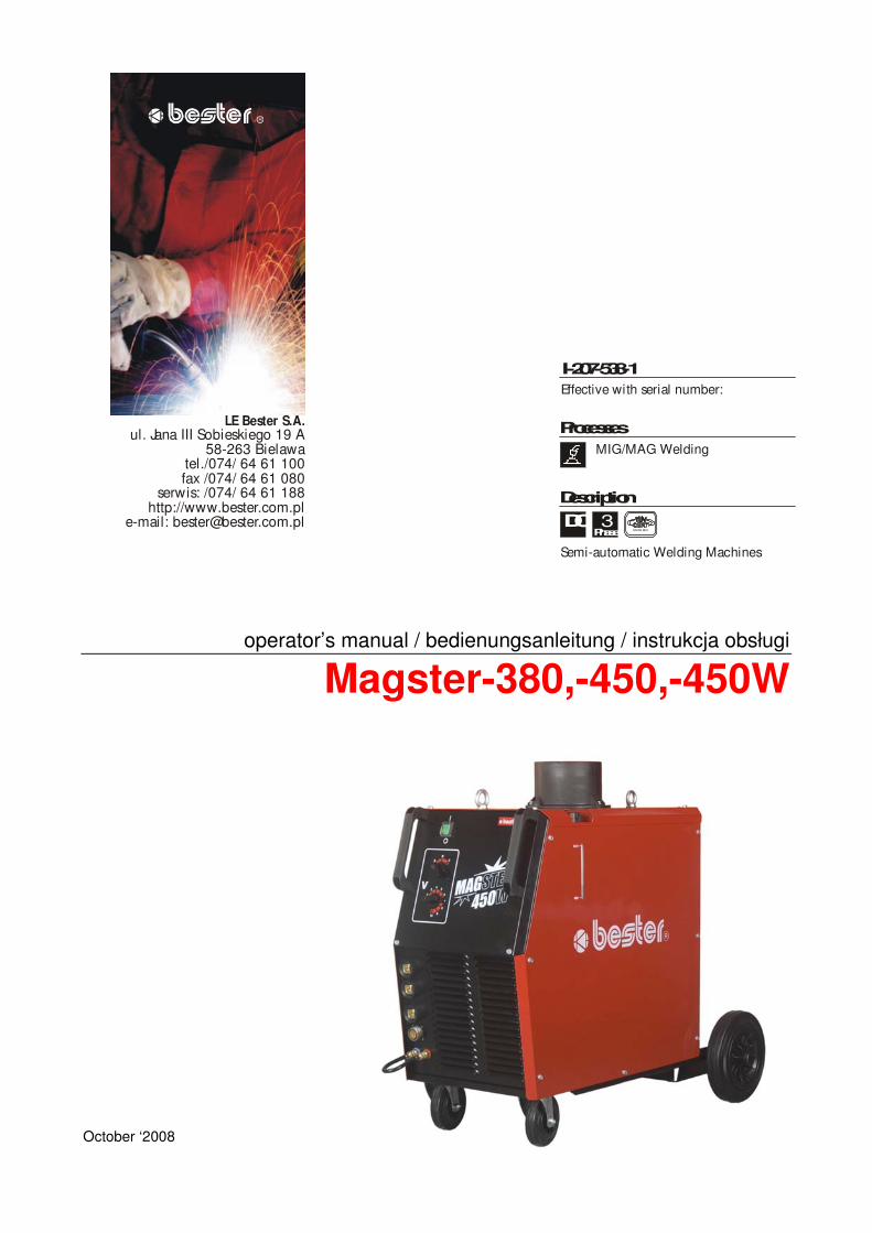
operator’s manual / bedienungsanleitung / instrukcja obsługi
Magster-380,-450,-450W
October ‘2008
ul. Jana III Sobieskiego 19 A58-263 Bielawa
tel./074/ 64 61 100fax /074/ 64 61 080
serwis: /074/ 64 61 188http://www.bester.com.pl
e-mail: [email protected]
LE Bester S.A.
R
I-207-538-1
Processes
Description
MIG/MAG Welding
Effective with serial number:
Semi-automatic Welding Machines
DC 3Phase E N ISO 9001
..

3
THANK YOU! For your appreciate of quality of LE Bester S.A. products.• Please check if the packaging and product aren’t damaged. The complaint of damage, which was accrued during
transportation must be submitted immediately for the deliverer (the distributor).• For convenience, please write the identification data of the product in this page, i.e. Model Name, Code and Serial
Number. You can find those date on the name plate of the product.
Wir Danken Ihnen! Für die Auswahl eins Qualitätsprodukts des LE Bester GmbH.� Prüfen Sie Bitte ob die Verpackung und die Einrichtung nicht beschädigt sind. Die Reklamationen der
Transportbeschädigungen sollen sofort an der Lieferant angemeldet werden.� Für Erleichterung schreiben Sie bitte auf diese Seite die identifizierungs Daten. Modell Name, Code undSeriennummer können Sie am Erzeugnisschild finden.
DZI KUJEMY! Za docenienie JAKO CI produktów LE Bester S.A..• Prosz sprawdzi czy opakowanie i sprz t nie s uszkodzone. Reklamacje uszkodze powstałych podczas
transportu musz by natychmiast zgłoszone do dostawcy (dystrybutora).• Dla ułatwienia prosimy o zapisanie na tej stronie danych identyfikacyjnych wyrobów. Nazwa modelu, Kod i Numer
Seryjny, które mo ecie Pa stwo znale na tabliczce znamionowej wyrobu.
Nie wyrzuca osprz tu elektrycznego razem z normalnymi odpadami!Zgodnie z Dyrektyw Europejsk 2002/96/EC dotycz c Pozbywania si zu ytego Sprz tu Elektrycznego iElektronicznego (Waste Electrical and Electronic Equipment, WEEE) i jej wprowadzeniem w ycie zgodnie zmi dzynarodowym prawem, zu yty sprz t elektryczny musi by składowany oddzielnie i specjalnie utylizowany.Jako wła ciciel urz dze powiniene otrzyma informacje o zatwierdzonym systemie składowania od naszegolokalnego przedstawiciela.Stosuj c te wytyczne b dziesz chronił rodowisko i zdrowie człowieka!
Die elektriche Einrichtungen soll man nicht zusammen mit Haushaltmühl hinauswerfen!Gemäß Europeische Direktive 2002/96/EC betrifft Gebrauchte Elektrische und Elektronische EinrichtungenLoswerden (WEEE) und Sie in Benutzung, gemäß Internationale Recht, Einführung gebrauchte elektrischeEinrichtungen sollen getrennt lagern sein und speziel utilisiert. Als Einrichtungen Besitzer sollen Sie die Auskunftüber bestätigten Lagersystem von unserem Ortsverträter bekommen.Diese Gesätze beobachten hilft Umwelt und Menschen Gesundheit schutzen.
Do not dispose of electrical equipment together with normal waste!In observance of European Directive 2002/96/EC on Waste Electrical and Electronic Equipment (WEEE) and itsimplementation in accordance with national law, electrical equipment that has reached the end of its life must becollected separately and returned to an environmentally compatible recycling facility. As the owner of theequipment, you should get information on approved collection systems from our local representative.By applying this European Directive you will protect the environment and human health!
Model Name/ Modell Name/Nazwa modelu:
………………...…………………………….…………………………………………………………………………………………..Code and Serial Number/ Code und Seriennummer/Kod i numer seryjny:
………………….……………………………………………….. …………………………………………………….……………..Purches Date and Place/ Datum- und Platz des Ankaufes/Data i miejsce zakupu:
…………………………………………………………………... ……………………….…………………………………………..

4
Declaration of conformity
Konformitätserklärung
Deklaracja zgodno ci
LE Bester S.A.
Declares that the welding machine:
Erklärt, daß die Bauart der Maschine:
Deklaruje, e spawalnicze ródło energii:
MAGSTER-380, -450, -450W s/n
conforms to the following directives:den folgenden Bestimmungen entspricht:
spełnia nast puj ce wytyczne:
73/23/CEE, 93/68/CEE, 89/336/CEE, 92/31/CEE
and has been designed in conformance with the following norms:und in Übereinstimmung mit den nachstehenden Normen hergestellt wurde:i e zostało zaprojektowane zgodnie z wymaganiami nast puj cych norm:
EN 50199, EN 60974-1
Paweł Lipi skiOperational Director
LE Bester S.A., ul. Jana III Sobieskiego 19A, 58-260 Bielawa, Poland10/08

5
ENGLISH INDEXSafety .............................................................................................................................................................................. 6Installation and Operator Instructions .............................................................................................................................. 7Electromagnetic Compatibility (EMC) ............................................................................................................................ 10Technical Specifications ................................................................................................................................................ 11
INHALTSVERZEICHNIS DEUTSCHSicherheitsmaßnahmen / Unfallschutz .......................................................................................................................... 12Installation und Bedienungshinweise............................................................................................................................. 13Elektromagnetische Verträglichkeit (EMC) .................................................................................................................... 16Technische Daten.......................................................................................................................................................... 17
SKOROWIDZ POLSKIBezpiecze stwo U ytkowania ....................................................................................................................................... 18Instrukcja Instalacji i Eksploatacji .................................................................................................................................. 19Kompatybilno Elektromagnetyczna (EMC)................................................................................................................. 22Dane Techniczne........................................................................................................................................................... 23
Spare Parts, Ersatzteile, Wykaz Cz ci Zamiennych .................................................................................................... 24Electrical Schematic, Elektrische Schaltpläne, Schemat Elektryczny............................................................................ 32Accessories, Zubehör, Akcesoria .................................................................................................................................. 35WEEE………………………………………………………………………………………………………………………………..36

6
Safety10/08
WARNINGThis equipment must be used by qualified personnel. Be sure that all installation, operation, maintenance and repairprocedures are performed only by qualified individuals. Read and understand this manual before operating thisequipment. Failure to follow the instructions in this manual could cause serious personal injury, loss of life, or damage tothis equipment. Read and understand the following explanations of the warning symbols. Lincoln Electric is notresponsible for damages caused by improper installation, improper care or abnormal operation.
WARNING: This symbol indicates that instructions must be followed to avoid serious personal injury,loss of life, or damage to this equipment. Protect yourself and others from possible serious injury ordeath.
READ AND UNDERSTAND INSTRUCTIONS: Read and understand this manual before operatingthis equipment. Arc welding can be hazardous. Failure to follow the instructions in this manual couldcause serious personal injury, loss of life, or damage to this equipment.
ELECTRIC SHOCK CAN KILL: Welding equipment generates high voltages. Do not touch theelectrode, work clamp, or connected work pieces when this equipment is on. Insulate yourself fromthe electrode, work clamp, and connected work pieces.
FUMES AND GASES CAN BE DANGEROUS: Welding may produce fumes and gases hazardous tohealth. Avoid breathing these fumes and gases. To avoid these dangers the operator must useenough ventilation or exhaust to keep fumes and gases away from the breathing zone.
ARC RAYS CAN BURN: Use a shield with the proper filter and cover plates to protect your eyes fromsparks and the rays of the arc when welding or observing. Use suitable clothing made from durableflame-resistant material to protect you skin and that of your helpers. Protect other nearby personnelwith suitable, non-flammable screening and warn them not to watch the arc nor expose themselves tothe arc.WELDING SPARKS CAN CAUSE FIRE OR EXPLOSION: Remove fire hazards from the weldingarea and have a fire extinguisher readily available. Welding sparks and hot materials from the weldingprocess can easily go through small cracks and openings to adjacent areas. Do not weld on anytanks, drums, containers, or material until the proper steps have been taken to insure that noflammable or toxic vapors will be present. Never operate this equipment when flammable gases,vapors or liquid combustibles are present.ELECTRICALLY POWERED EQUIPMENT: Turn off input power using the disconnect switch at thefuse box before working on this equipment. Ground this equipment in accordance with local electricalregulations.
ELECTRICALLY POWERED EQUIPMENT: Regularly inspect the input, electrode, and work clampcables. If any insulation damage exists replace the cable immediately. Do not place the electrodeholder directly on the welding table or any other surface in contact with the work clamp to avoid therisk of accidental arc ignition.ELECTRIC AND MAGNETIC FIELDS MAY BE DANGEROUS: Electric current flowing through anyconductor creates electric and magnetic fields (EMF). EMF fields may interfere with somepacemakers, and welders having a pacemaker should consult their physician before operating thisequipment.WELDED MATERIALS CAN BURN: Welding generates a large amount of heat. Hot surfaces andmaterials in work area can cause serious burns. Use gloves and pliers when touching or movingmaterials in the work area.
CE COMPLIANCE: This equipment complies to the European Communities directives.
SAFETY MARK: This equipment is suitable for supplying power for welding operations carried out inan environment with increased hazard of electric shock.

7
CYLINDER MAY EXPLODE IF DAMAGED: Use only compressed gas cylinders containing thecorrect shielding gas for the process used and properly operating regulators designed for the gas andpressure used. Always keep cylinders in an upright position securely chained to a fixed support. Donot move or transport gas cylinders with the protection cap removed. Do not allow the electrode,electrode holder, work clamp or any other electrically live part to touch a gas cylinder. Gas cylindersmust be located away from areas where they may be subjected to physical damage or the weldingprocess including sparks and heat sources.
Installation and Operator Instructions
Read this entire section before installation or operationof the machine.
Location and EnvironmentThis machine will operate in harsh environments.However, it is important that simple preventativemeasures are followed to assure long life and reliableoperation.
• Do not place or operate this machine on a surfacewith an incline greater than 10°from horizontal.
• This machine must be located where there is freecirculation of clean air without restrictions for airmovement to and from the air vents. Do not coverthe machine with paper, cloth or rags whenswitched on.
• Dirt and dust that can be drawn into the machineshould be kept to a minimum.
• This machine has a protection rating of IP21. Keepit dry when possible and do not place it on wetground or in puddles.
• Locate the machine away from radio controlledmachinery. Normal operation may adversely affectthe operation of nearby radio controlled machinery,which may result in injury or equipment damage.Read the section on electromagnetic compatibility inthis manual.
• Do not use this machine for pipe thawing.• Do not operate in areas with an ambient
temperature greater than 40°C.
Duty Cycle and OverheatingThe duty cycle of a welding machine is the percentage oftime in a 10 minute cycle at which the welder canoperate the machine at rated welding current.
Example: 60% Duty Cycle:
Welding for 6 minutes. Break for 4 minutes.
Excessive extension of the duty cycle will cause thethermal protection circuit to activate. See “TechnicalSpecification”.
Minutes or decreaseDuty Cycle
Input Supply Connection
WARNINGEquipment shall only be used on a supply systemthat is a three-phase, four-wire system with anearthed neutral.
Installation and mains outlet socket shall be made andprotected according to appropriate rules. Check the inputvoltage, phase, and frequency supplied to this machinebefore turning it on. For more information about inputsupply refer to the technical specification section of thismanual and to the rating plate of the machine. Verify theconnection of grounding wires from the machine to theinput source.
Wire Feeder ConnectionTo connect the wire feeder to the power source Magster380 or 450 you should use the combined cable (seechapter “Accessories”) and do the following:� Connect the combined cable to the socket marked by
.� Connect the control cable to the socket marked by
To connect the wire feeder to the semi power sourceMagster 450W you should use the combined cable (seechapter “Accessories”) and do the following:� Connect the combined cable to the socket marked by
.� Connect the control cable to the socket marked by
.� Disconnect the hose, which closes the circuit of the
water cooling system and connect hoses to thewelding source and wire feeder according to colourmarks (the blue hose to the socket with bluebordering).
Wire diagram of the welding source and wire feeder isshown in the chapter “Wiring Diagrams”.
Ground Cable ConnectionConnect the ground cable to one of the two sockets ,additionally marked by:� : high inductance output socket.� : low inductance output socket.
Shielding Gas ConnectionTo connect shielding gas you should do the following:� After placing the gas cylinder on the gas cylinder
mount, protect it from overturn with the chain.� Take off the cap over the safety valve of the shielding
gas cylinder.

8
� Install the gas regulator on the gas cylinder.� Connect the shielding gas cylinder to the wire feeder
with the gas hose of the combined cable, usingclamping band.
� Welding with CO2 as shielding gas, you should usethe gas heater which can be supplied from thesocket on the rear panel of the welder.
Controls and Operational Features
1. Power Switch: Turns the machine on/off. Switchingon is indicated by lighting up of the switch button.
2. Welding Voltage Changing Switch: 3-step switchenables welding voltage step selection.
WARNINGIt is not allowed changing the welding voltage rangeduring welding process. It may damage the switch.
3. Welding Voltage Changing Switch: 10-step switchenables welding voltage step selection.
WARNINGIt is not allowed changing the welding voltage rangeduring welding process. It may damage the switch.
4. Output Socket with High Inductance: For connectingthe ground cable. The high inductance connection ismore suitable for short arc welding in heavier workor when using mix Ar+CO2 shielding gas.
5. Output Socket with Low Inductance: For connectingthe ground cable. The low inductance connection istypically used for short arc welding of mild steel,particularly on thin materials or when using CO2
shielding gas.
6. Positive Output Socket: For connecting the weldingcable to the wire feeder.
7. Control Socket: 7-pin socket for connecting thecontrol cable to control the welding source and tosupply the wire feeder from the welding source.
8. Quick Water Connector of the Cooling System:
For connecting hoses of the water cooling system.(Magster 450W only).
Rear Panel
1. Bracket: for fastening the gas cylinder.WARNING
After installation, protect the shielding gas cylinderfrom overturn with the chain.
2. Gas Heater Socket: Usup = 24VAC, Pmax = 80W.
3. Fuse Socket F3: The recommended fuse: 4A/400V(6,3x32mm).
WARNINGYou have to use fuses with Technical Specifica-tions given by the producer.
4. Fuse Socket F2: The recommended fuse:6,3A/400V (6,3x32mm).
WARNINGYou have to use fuses with Technical Specifica-tions given by the producer.
5. Fuse Socket F1: The recommended fuse: 3A/400V(6,3x32mm).
WARNINGYou have to use fuses with Technical Specifica-tions given by the producer.
6. Power Input Cable.
7. Gas Cylinder Mount.

9
Water Cooling System (Magster 450W only)
1. Reservoir FillerWARNING
You have to use coolant with technical specifica-tions given by the producer.Do not add water and other cooling medium to thecoolant.Do not use automotive anti-freeze that containsrust inhibitors or leak stoppers.Do not use pre-packaged welding industrycoolants. These coolants may contain oil-basedsubstances, which attack the plastic componentsof the cooling system.
2. Coolant Level Checking Window: The maximumcoolant level is indicated by the MAX marker, theminimum level is indicated by the MIN marker.
WARNINGDo not operate machine without coolant inreservoir. Never run pump dry
.3. Cooling System Looping Hose
WARNINGYou have to connect cooling system looping hosewhen you use gas cooled welding gun. Otherwiseit may damage cooling system pump.
Final Actions� Connect the ground cable to the work piece with the
work clamp.� Connect the shielding gas cylinder to the shielding gas
input through the gas regulator.� Insert the plug of the power input cable of the welder
into the mains socket.� Switch on the power source with the power switch. It
is indicated by lighting up of the switch button.� Based on the seam kind, join type and material
thickness of the work piece, chose correct weldingsettings with the welding voltage switch and wirefeeder controls.
� Obeying the appropriate rules, begin to weld.
Setting Welding Voltage

10
Electromagnetic Compatibility (EMC)10/08
This machine has been designed in accordance with all relative directives and norms. However, it may still generateelectromagnetic disturbances that can affect other systems like telecommunications (telephone, radio, and television) orother safety systems. These disturbances can cause safety problems in the affected systems. Read and understandthis section to eliminate or reduce the amount of electromagnetic disturbance generated by this machine.
This machine has been designed to operate in an industrial area. To operate in a domestic area it isnecessary to observe particular precautions to eliminate possible electromagnetic disturbances. Theoperator must install and operate this equipment as described in this manual. If any electromagneticdisturbances are detected the operator must put in place corrective actions to eliminate these disturbances
with, if necessary, assistance from Lincoln Electric.
Before installing the machine, the operator must check the work area for any devices that may malfunction because ofelectromagnetic disturbances. Consider the following.• Input and output cables, control cables, and telephone cables that are in or adjacent to the work area and the
machine.• Radio and/or television transmitters and receivers. Computers or computer controlled equipment.• Safety and control equipment for industrial processes. Equipment for calibration and measurement.• Personal medical devices like pacemakers and hearing aids.• Check the electromagnetic immunity for equipment operating in or near the work area. The operator must be sure
that all equipment in the area is compatible. This may require additional protection measures.• The dimensions of the work area to consider will depend on the construction of the area and other activities that are
taking place.
Consider the following guidelines to reduce electromagnetic emissions from the machine.• Connect the machine to the input supply according to this manual. If disturbances occur if may be necessary to take
additional precautions such as filtering the input supply.• The output cables should be kept as short as possible and should be positioned together. If possible connect the
work piece to ground in order to reduce the electromagnetic emissions. The operator must check that connectingthe work piece to ground does not cause problems or unsafe operating conditions for personnel and equipment.
• Shielding of cables in the work area can reduce electromagnetic emissions. This may be necessary for specialapplications.

11
Technical Specifications
MAGSTER 380, -450, -450W
INPUT PARAMETERS
Input VoltageMaximum Input
CurrentMaximum Power
Consumption Frequency PowerFactor
MAGSTER 380 25 A 17.3 kVA400V ± 10%Three Phase
MAGSTER 450 32 A 21.5 kVA 50 Hertz(Hz) 0.96MAGSTER 450W 32 A 21.8 kVA
OUTPUT PARAMETERSDuty Cycle
(Based on a 10 min. period) Output Current Welding CurrentRange
Output CircuitVoltage
Welding VoltageSteps
MAGSTER 380 40 %60 %
100 %
360 A295 A225 A
40 – 360 A 18 – 47.5 V 30
MAGSTER 450 40 %60 %
100 %
420 A345 A265 A
40 – 420 A 18 – 51 V 30
MAGSTER 450W 40 %60 %
100 %
420 A345 A265 A
40 – 420 A 18 – 51 V 30
OTHER PARAMETERSDegree
ProtectionInsulation
ClassEMC
ClassificationOperating
TemperatureOperatingHumidity
DimensionsW x H x D
IP21 H Group2, Class A from -10 to +40 �C �90 % 570 x 910 x 1010 mmRECOMMENDED INPUT CABLE AND FUSE SIZES
WEIGHTFuse or Circuit Breaker Size Input CableMAGSTER 380 25 A Superlag
4x2.5mm2MAGSTER 380 145 kg
MAGSTER 450 32 A Superlag MAGSTER 450 154 kgMAHSTER 450W 32 A Superlag MAHSTER 450W 161 kg
For any maintenance or repair operations it is recommended to contact the nearest technical service center or LE BesterS.A. Maintenance or repairs performed by unauthorized service centers or personnel will null and void themanufacturers warranty.

12
Sicherheitsmaßnahmen / Unfallschutz10`/08
ACHTUNGDiese Anlage darf nur von ausgebildeten Leuten benutzt, gewartet und repariert werden. Schließen Sie dieses Gerätnicht an, arbeiten Sie nicht damit oder reparieren Sie es nicht, bevor Sie diese Betriebsanleitung gelesen und verstandenhaben. Bei Nichtbeachtung der Hinweise kann es zu gefährlichen Verletzungen bis hin zum Tod oder zuBeschädigungen am Gerät kommen. Beachten Sie auch die folgenden Beschreibungen der Warnhinweise. LincolnElectric ist nicht verantwortlich für Fehler, die durch inkorrekte Installation, mangelnde Sorgfalt oder Fehlbenutzung desGerätes entstehen.
ACHTUNG: Dieses Symbol gibt an, dass die folgenden Hinweise beachtet werden müssen, umgefährliche Verletzungen bis hin zum Tode oder Beschädigungen am Gerät zu verhindern. SchützenSie sich und andere vor gefährlichen Verletzungen oder dem Tode.
BEACHTEN SIE DIE ANLEITUNG: Lesen Sie diese Anleitung sorgfältig, bevor Sie das Gerät inBetrieb nehmen. Bei Nichtbeachtung der Hinweise kann es zu gefährlichen Verletzungen bis hin zumTod oder zu Beschädigungen am Gerät kommen.
STROMSCHLÄGE KÖNNEN TÖDLICH SEIN: Schweißgeräte erzeugen hohe Stromstärken.Berühren Sie keine stromführenden Teile oder die Elektrode mit der Haut oder nasser Kleidung.Schützen Sie beim Schweißen Ihren Körper durch geeignete isolierende Kleidung und Handschuhe.
RAUCH UND GASE KÖNNEN GEFÄHRLICH SEIN: Schweißen erzeugt Rauch und Gase, diegesundheitsschädlich sein können. Vermeiden Sie das Einatmen dieser Metalldämpfe. Benutzen Sieeine Schweißrauchabsaugung, um die Dämpfe abzusaugen.
LICHTBÖGEN KÖNNEN VERBRENNUNGEN HERVORRUFEN: Tragen Sie geeignete Schutz-kleidungen und Schutzmasken für Augen, Ohren und Körper, um sich vor Spritzern und Strahlungenzu schützen. Warnen Sie auch in der Umgebung befindliche Personen vor den Gefahren desLichtbogens. Lassen Sie keinen ungeschützt den Lichtbogen beobachten.SCHWEISSPRITZER KÖNNEN FEUER ODER EXPLOSIONEN VERURSACHEN: Entfernen Siefeuergefährliche Gegenstände vom Schweißplatz und halten Sie einen Feuerlöscher bereit.Schweißen Sie keine Behälter, die brennbare oder giftige Stoffe enthalten, bis diese vollständiggeleert und gesäubert sind. Schweißen Sie niemals an Orten, an denen brennbare Gase, Stoffe oderFlüssigkeiten vorhanden sind.ELEKTRISCHE GERÄTE: Schalten Sie die Netzspannung am Sicherungskasten aus oder ziehen Sieden Netzstecker, bevor Arbeiten an der Maschine ausgeführt werden. Erden Sie die Maschinegemäß den geltenden elektrischen Bestimmungen.
ELEKTRISCHE GERÄTE: Achten Sie regelmäßig darauf, dass Netz-, Werkstück- und Elektro-denkabel in einwandfreiem Zustand sind und tauschen Sie diese bei Beschädigung aus. Legen Sieden Elektrodenhalter niemals auf den Schweißarbeitsplatz, damit es zu keinem ungewolltenLichtbogen kommt.ELEKTRISCHE UND MAGNETISCHE FELDER BERGEN GEFAHREN: Elektrischer Strom, derdurch ein Kabel fließt erzeugt, ein elektrisches und magnetisches Feld (EMF). EMF Felder könnenHerzschrittmacher beeinflussen. Bitte fragen Sie Ihren Arzt, wenn Sie einen Herzschrittmacherhaben, bevor Sie dieses Gerät benutzen.DEFEKTE GASFLASCHEN KÖNNEN EXPLODIEREN: Benutzen Sie nur Gasflaschen mit dem fürden Schweißprozess geeigneten Gas und ordnungsgemäßen Druckreglern, die für dieses Gasausgelegt sind. Lagern Sie Gasflaschen aufrecht und gegen Umfallen gesichert. Bewegen Sie keineGasflasche ohne Ihre Sicherheitskappe. Berühren Sie niemals eine Gasflasche mit der Elektrode,Elektrodenhalter, Massekabel oder einem anderen stromführenden Teil. Gasflaschen dürfen nicht anPlätzen aufgestellt werden, an denen sie beschädigt werden können, inklusive Schweißspritzern undWärmequellen.GESCHWEISSTE MATERIALIEN KÖNNEN VERBRENNUNGEN VERURSACHEN: Schweißen ver-ursacht hohe Temperaturen. Heiße Materialien können somit ernsthafte Verbrennungen verursachen.Benutzen Sie Handschuhe und Zangen, wenn Sie geschweißte Materialien berühren oder bewegen.
CE Konformität: Dieses Gerät erfüllt die CE-Normen.

13
S-ZEICHEN: Dieses Gerät darf Schweißstrom in Umgebungen mit erhöhter elektrischer Gefährdungliefern.
Installation und Bedienungshinweise
Lesen Sie bitte sorgfältig diese Bedienungsanleitung, bevor Sie das Gerät anschließen oder in Betrieb nehmen.
Standort und Umgebungsbedingungen
Diese Einrichtung kann im schweren Bedingungenarbeiten.Dennoch sollten die folgenden Punkte für einelange Lebensdauer beachtet werden.
• Stellen Sie das Gerät nicht auf Ebenen mit mehr als10°horizontaler Neigung.
• Die Einrichtung muss an einem Ort installiert werden,an dem eine freie und saubere Luftzirkulationgewährleistet ist. Bedecken Sie die Maschine nichtmit Papier, Stoff oder Plane, wenn sie eingeschaltetist.
• Schmutz, Staub, der in die Maschine gelangen kann,sollte auf ein Minimum reduziert werden.
• Diese Maschine ist nach IP21 geschützt. Halten Siedie Maschine trocken, und stellen Sie diese nicht aufnassen Untergrund oder in Wasserpfützen.
• Halten Sie die Einrichtung von elektronischenAnlagen mit funksteuerung fern. NormalerSchweissvorgang kann zu Störungen dieser Anlagenführen, was Körperverletzung oder Einrichtungbeschädigung wirken kann. Lesen Sie hierzu auchdas Kapitel "Elektromagnetische Verträglichkeit".
• Zum Aufheben der Einrichtung soll ein Kran benuztwerden.
• Die Schweißquelle darf nicht zu Rohrenauftauenbenutzt werden.
• Betreiben Sie die Einrichtung nicht bei Temperaturenüber 40°C.
Die Einschaltdauer und Überhitzung
Die Arbeitzyklus der Einrichtung ist ein Prozentteilung10 Min. Zyklus wenn man mit normativem Stromschweißen kann.
Beispiel : 60% Arbeitszyklus
6 Min. Schweißen 4 Min. Pause
Übermäßige Verlängerung der Arbeitszyklus kann derThermoschutz der Einrichtung aktivieren.Mehr Auskunft über die Arbeitzyklus im Abschnitt‘Technische Daten’.
Anschluß an das Stromversorgungs-netz
ACHTUNGDie Einrichtung kann nur im 3 Phasen, 4 LeitungenSchaltkreis mit Nullpunkt am Erde benutzt sein..
Der Anschluß der Stromquelle an das Versorgungsnetzsowie auch nach Schutzerdungsystem muß man sach-und Vortschriftsgemäßig durchgeführt sein. Vor jedemNetzanschluß zuerst der Hauptschalter in Stellung ‘0’(Ausgeschaltet) umstellen. Zulässige Anspeise Span-nungwert , Netzfrequenz, und Überstrom Schutzwertist am Einrichtungsschild und im Abschnitt ‘TechnischeDaten’ gegeben. Die Erdanschluß zwischen Schweiß-quelle und Anspeisenetz prüfen.
Zusammenstellung der Stromquellemit dem Schweißdrahtaufgeber
Ist die Verbindung der Stromquelle Magster 380,Magster 450 mit dem Schweißdrahtaufgeberdurchgeführt so muß man Zuleitungspaket geeigneteLänge benutzen (Sehe Abschn. ‘Zubehör’) undfolgendes tun :� Der Schweißleiter zu Buchse mit markierung
anschließen.� Der Steuerleiter zu Buchse mit markierung
anschließen.
Ist die Verbindung der Stromquelle Magster 450W mitdem Schweißdrahtaufgeber durchgeführt so muß manZuleitungspaketgeeignete Länge benutzen (SeheAbschn. ‘Zubehör’) und fogebdes tun:� Der Schweißleiter zu Buchse mit markierung
anschließen.� Der Steuerleiter zu Buchse mit markierung
anschließen.� Der Schlauch der Kühlsystem schließt abnehmen und
die Schlauche zwischen die Stromquelle undSchweißdrahtaufgeber anschließen. Dabei ist zubeachten daß die Farben der Schläuche mit Farbender Schnellverbinder übereinstimmen (blaueSchlauch zu Schnellverbinder mit blaue Kreis, roteSchlauch zu Schnellverbinder mit rote Kreis).
Schaltkreis der Verbindungen zwischen Scweiß-drahtaufgeber und Stromquelle ist im Abschnitt‘Schaltkreis der Verbindungen’ gezeigt.
14
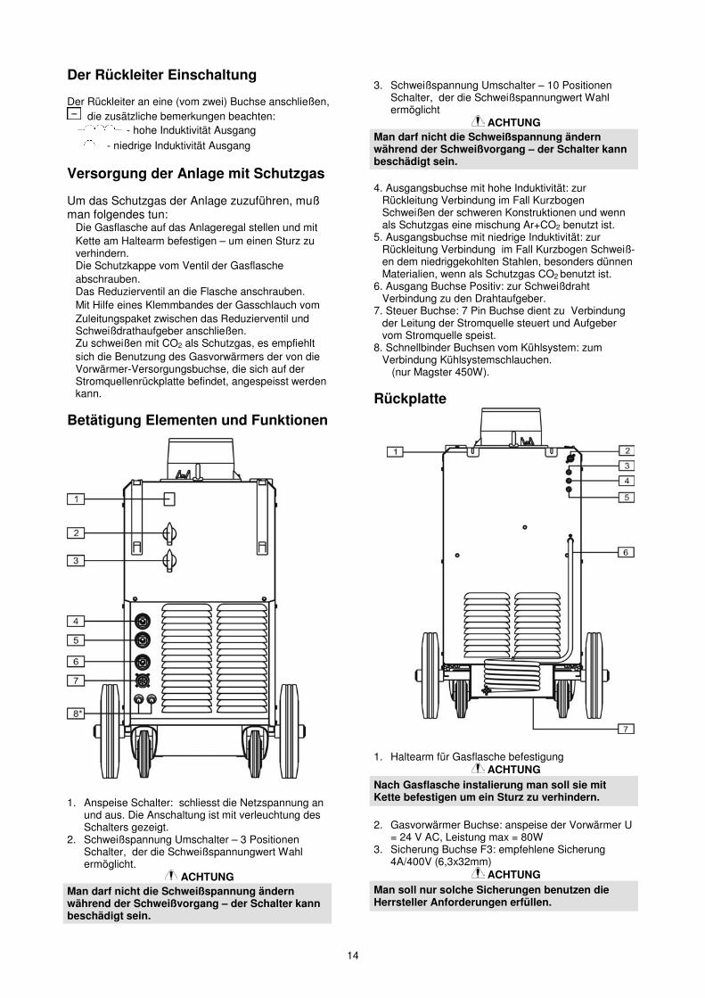
Der Rückleiter Einschaltung
Der Rückleiter an eine (vom zwei) Buchse anschließen,die zusätzliche bemerkungen beachten:
� - hohe Induktivität Ausgang� - niedrige Induktivität Ausgang
Versorgung der Anlage mit Schutzgas
Um das Schutzgas der Anlage zuzuführen, mußman folgendes tun:� Die Gasflasche auf das Anlageregal stellen und mit
Kette am Haltearm befestigen – um einen Sturz zuverhindern.
� Die Schutzkappe vom Ventil der Gasflascheabschrauben.
� Das Reduzierventil an die Flasche anschrauben.� Mit Hilfe eines Klemmbandes der Gasschlauch vom
Zuleitungspaket zwischen das Reduzierventil undSchweißdrathaufgeber anschließen.
� Zu schweißen mit CO2 als Schutzgas, es empfiehltsich die Benutzung des Gasvorwärmers der von dieVorwärmer-Versorgungsbuchse, die sich auf derStromquellenrückplatte befindet, angespeisst werdenkann.
Betätigung Elementen und Funktionen
1. Anspeise Schalter: schliesst die Netzspannung anund aus. Die Anschaltung ist mit verleuchtung desSchalters gezeigt.
2. Schweißspannung Umschalter – 3 PositionenSchalter, der die Schweißspannungwert Wahlermöglicht.
ACHTUNGMan darf nicht die Schweißspannung ändernwährend der Schweißvorgang – der Schalter kannbeschädigt sein.
3. Schweißspannung Umschalter – 10 PositionenSchalter, der die Schweißspannungwert Wahlermöglicht
ACHTUNGMan darf nicht die Schweißspannung ändernwährend der Schweißvorgang – der Schalter kannbeschädigt sein.
4. Ausgangsbuchse mit hohe Induktivität: zurRückleitung Verbindung im Fall KurzbogenSchweißen der schweren Konstruktionen und wennals Schutzgas eine mischung Ar+CO2 benutzt ist.
5. Ausgangsbuchse mit niedrige Induktivität: zurRückleitung Verbindung im Fall Kurzbogen Schweiß-en dem niedriggekohlten Stahlen, besonders dünnenMaterialien, wenn als Schutzgas CO2 benutzt ist.
6. Ausgang Buchse Positiv: zur SchweißdrahtVerbindung zu den Drahtaufgeber.
7. Steuer Buchse: 7 Pin Buchse dient zu Verbindungder Leitung der Stromquelle steuert und Aufgebervom Stromquelle speist.
8. Schnellbinder Buchsen vom Kühlsystem: zumVerbindung Kühlsystemschlauchen.
(nur Magster 450W).
Rückplatte
1. Haltearm für Gasflasche befestigungACHTUNG
Nach Gasflasche instalierung man soll sie mitKette befestigen um ein Sturz zu verhindern.
2. Gasvorwärmer Buchse: anspeise der Vorwärmer U= 24 V AC, Leistung max = 80W
3. Sicherung Buchse F3: empfehlene Sicherung4A/400V (6,3x32mm)
ACHTUNGMan soll nur solche Sicherungen benutzen dieHerrsteller Anforderungen erfüllen.

15
4. Sicherung Buchse F2: emfehlene Sicherung 6,3A/400 V(6,3x32 mm)
ACHTUNGMan soll nur solche Sicherungen benutzen dieHerrsteller Anforderungen erfüllen.
5. Sicherung Buchse F1: emfehlene Sicherung 3 A/400V(6,3x32 mm)
ACHTUNGMan soll nur solche Sicherungen benutzen dieHerrsteller Anforderungen erfüllen.
6.Netzleitung: zum Schweißquelle Anspeisung.7. Anlageregal für die Flasche mit Schutzgas.
Kühlsystem (nur Magster 450W)
Zeichnung
1.Kühlflüssigkeit Einguß:ACHTUNG
Es empfiehlt sich die Anwendung derKühlflüssigkeit die der Herrsteller angeben hat.Eine Mischung dieser Flüssigkeit mit anderen odermit Wasser ist verboten.Man soll auch keine nichtzufrierene Flüssigkeitendie zum Autokühler vorgesehen sind benutzen,wegen Antikorrosion und Abdichtung Zutaten dieUngünstig auf Kühlsystemelementen wirkenkönnen.Auch keine Industriele Kühlflüssigkeitenanwenden. Diese Kühlflüssigkeiten können die Öl-Ursprung Stoffe enthalten, die Ungünstig aufPlastelemenen im Kühlsystem wirken können.
2. Kühlflüssigkeitpegel Anzeiger: Flüssigkeitpegel sollzwischen MIN und MAX markierung bleiben.
ACHTUNGDer Betrieb des Einrichtung ohne Kühlflüssigkeitoder mit zu niedrigem Flüssigkeit Pegel imKühlsystem kann die Pumpebeschädigung zurFolge haben.Achtung: Der Betrieb des Einrichtung ohneKühlflüssigkeit oder mit zu niedrigem FlüssigkeitPegel im Kühlsystem kann die Pumpebeschädigungzur Folge haben.3. Klammerschlauch für Kühlschaltkreis Schließung.
ACHTUNGIm Fall wenn den Schweißgriff ohne Kühlsystemanwenden, Kühlschaltkreis soll mit Klammer-schlauch geschlossen werden. Eine Nichtanwen-dung kann die Pumpebeschädigung zur Folgehaben.
Die Schlußtätigkeiten
� Die Rückleitung an schweißenden Werkstück mitKlemme verbinden.
� Die Flasche mit Schutzgas über Reduzierventil anSchutzgaseingang verbinden.
� Der Stromquelle Anspeisenetz Stecker an dieVersorgungsnetz Buchse anschalten.
� Die Stromquelle mit Hauptschalter einschalten, wasdie Erleuchtung des Schalters signalisiert.
� Gemäß der Nahtart, Verbindungsart und je nachStärke der Werkstücke die entsprechendeSchweißeinstellungen mit Hilfe SchweißspannungUmschalter und Regulierungselementen desDrathaufgeber wählen.
� Unter Beachtung der entsprechendenSicherheitsvortschriften kann mit dem Schweißenbegonnen werden. Die Seitendeckel desHalbautomaten öfnen.
Die Schweißspannung Auswahl

16
Elektromagnetische Verträglichkeit (EMC)10/08
Diese Maschine wurde unter Beachtung aller zugehörigen Normen und Vorschriften gebaut. Dennoch kann es unterbesonderen Umständen zu elektromagnetischen Störungen anderer elektronischer Syteme (z.B. Telefon, Radio, TV,Computer usw. ) kommen. Diese Störungen können im Extremfall zu Sicherheitsproblemen der beeinflussten Systemeführen. Lesen Sie deshalb diesen Abschnitt aufmerksam durch, um das Auftreten elektromagnetischer Störungen zureduzieren oder ganz zu vermeiden.
Diese Maschine ist für den industriellen Einsatz konzipiert worden. Bei Benutzung dieser Anlage in Wohn-gebieten sind daher besondere Vorkehrungen zu treffen, um Störungen durch elektromagnetischeBeeinflussungen zu vermeiden. Halten Sie sich stets genau an die in dieser Bedienungsanleitung genanntenEinsatzvorschriften. Falls dennoch elektromagnetische Störungen auftreten, müssen geeignete Gegen-
maßnahmen getroffen werden. Kontaktieren Sie gegebenenfalls den Kundendienst der Lincoln Smitweld GmbH.Technische Änderungen der Anlage sind nur nach schriftlicher Genehmigung des Herstellers zulässig.
Vergewissern Sie sich vor der Inbetriebnahme des Schweißgerätes, dass sich keine für elektromagnetische Störungenempfänglichen Geräte und Anlagen im möglichen Einflussbereich befinden. Dies gilt besonders für:• Steuerleitungen, Datenkabel und Telefonleitungen,• Radio und Televisions-Sender oder -Empfänger sowie deren Kabelverbindungen,• Computer oder computergesteuerte Anlagen,• elektronische Sicherheitseinrichtungen und Steuereinheiten für industrielle Anlagen,• elektronische Mess- und Kalibriereinrichtungen,• medizinische Apparate und Geräte, Hörgeräte oder persönliche Implantate wie Herzschrittmacher usw. Achtung!
Informieren Sie sich vor Inbetriebnahme der Anlage in der Nähe von Kliniken und Krankenhäusern über die hierzugültigen Vorschriften, und sorgen Sie für die exakte Einhaltung aller erforderlichen Sicherheitsmaßnahmen!
• Prüfen Sie grundsätzlich die elektromagnetische Verträglichkeit von Geräten, die sich im Einflussbereich derSchweißanlage befinden.
• Dieser Einflussbereich kann in Abhängigkeit der physikalischen Umstände in seiner räumlichen Ausdehnung starkvariieren.
Befolgen Sie zusätzlich die folgenden Richtlinien um elektromagnetische Abstrahlungen zu reduzieren:• Schließen Sie die Maschine stets nur wie beschrieben an. Falls dennoch Störungen auftreten, muss eventuell ein
zusätzlicher Netzfilter eingebaut werden.• Halten Sie die Länge der Schweißkabel möglichst auf ein erforderliches Mindestmaß begrenzt.• Wenn möglich, sollte das Werkstück separat geerdet werden. Beachten Sie stets bei allen Maßnahmen, dass
hierdurch keinerlei Gefährdung von direkt oder indirekt beteiligten Menschen verursacht wird.

17
Technische Daten
MAGSTER 380, -450, -450W
Eingangs Daten
EingangsspannungMaximale
Stromaufnahme
MaximaleLeistungsauf-
nahme Frequenz Leistungs-faktor
MAGSTER 380 25 A 17,3 kVA
400V ± 10%Drei Phasen
MAGSTER 450 32 A 21,5 kVA50 Hz 0,96
MAGSTER 450W 32 A 21,8 kVAAusgangs Daten
Einschaltdauer(basierend auf 10 min. -Zyklus)
Schweißstrom Schweißstrombereich Ausgangs-spannung
SchweißstufenAnzahl
MAGSTER 38040 %60 %
100 %
360 A295 A225 A
40 – 360 A 18 – 47,5 V 30
MAGSTER 45040 %60 %
100 %
420 A345 A265 A
40 – 420 A 18 – 51 V 30
MAGSTER450W
40 %60 %
100 %
420 A345 A265 A
40 – 420 A 18 – 51 V 30
Andere Daten
GehäuseSchutzgrad
IsolationSchutz-
grad
EMCKlassifizierung
ZulässigeUmgebungstem-
peraturenFeuchtigkeit Abmessungen
LxHxT
IP21 H Gruppe2Klasse A von -10 bis +40 �C �90 % 570 x 910 x 1010 mmPrimärkabelquerschnitte und Absicherung
GewichtSicherungen oder Überstromschaltern. PrimärkabelMAGSTER 380 25 A Superträge
4x2,5mm2
MAGSTER 380 145 kg
MAGSTER 450 32 A . Superträge MAGSTER 450 154 kg
MAHSTER 450W 32 A Superträge MAHSTER 450W 161 kgFür Wartung und Reparatur des Gerätes konsultieren Sie bitte Ihren Fachhändler oder die LE Bester GmbH. Eine unsachgemäßdurchgeführte Wartung oder Reparatur durch eine nicht qualifizierte Person führt zum Erlöschen der Garantie

18
Bezpiecze stwo U ytkowania10/08
OSTRZE ENIEUrz dzenie to mo e by u ywane tylko przez wykwalifikowany personel. Nale y by pewnym, e instalacja, obsługa,przegl dy i naprawy s przeprowadzane tylko przez osoby wykwalifikowane. Instalacji i eksploatacji tego urz dzeniamo na dokona tylko po dokładnym zapoznaniu si z t instrukcj obsługi. Nieprzestrzeganie zalece zawartych w tejinstrukcji mo e narazi u ytkownika na powa ne obra enie ciała, mier lub uszkodzenie samego urz dzenia. LincolnElectric nie ponosi odpowiedzialno ci za uszkodzenia spowodowane niewła ciw instalacj , niewła ciw konserwacjlub nienormaln obsług .
OSTRZE ENIE: Symbol ten wskazuje, e bezwzgl dnie musz by przestrzegane instrukcje dlaunikni cia powa nego obra enia ciała, mierci lub uszkodzenia samego urz dzenia. Chro siebie iinnych przed mo liwym powa nym obra eniem ciała lub mierci .
CZYTAJ ZE ZROZUMIENIEM INSTRUKCJ : Przed rozpocz ciem u ytkowania tego urz dzeniaprzeczytaj niniejsz instrukcj ze zrozumieniem. Łuk spawalniczy mo e by niebezpieczny.Nieprzestrzeganie instrukcji tutaj zawartych mo e spowodowa powa ne obra enia ciała, mier lubuszkodzenie samego urz dzenia.PORA ENIE ELEKTRYCZNE MO E ZABI : Urz dzenie spawalnicze wytwarza wysokie napi cie.Nie dotyka elektrody, uchwytu spawalniczego lub podł czonego materiału spawanego, gdyurz dzenie jest zał czone do sieci. Odizolowa siebie od elektrody, uchwytu spawalniczego ipodł czonego materiału spawanego.OPARY I GAZY MOG BY NIEBEZPIECZNE: W procesie spawania mog powstawa opary i gazyniebezpieczne dla zdrowia. Unika wdychania tych oparów i gazów. Dla unikni cia takiego ryzykamusi by zastosowana odpowiednia wentylacja lub wyci g usuwaj cy opary i gazy ze strefyoddychania.PROMIENIE ŁUKU MOG POPARZY : Stosowa mask ochronn z odpowiednim filtrem i osłonydla zabezpieczenia oczu przed promieniami łuku podczas spawania lub jego nadzoru. Dla ochronyskóry stosowa odpowiedni odzie wykonan z wytrzymałego i niepalnego materiału. Chronipersonel postronny, znajduj cy si w pobli u, przy pomocy odpowiednich, niepalnych ekranów lubostrzega ich przed patrzeniem na łuk lub wystawianiem si na jego oddziaływanie.ISKRY MOG SPOWODOWA PO AR LUB WYBUCH: Usuwa wszelkie zagro enie po arem zobszaru prowadzenia prac spawalniczych. W pogotowiu powinny by odpowiednie rodki ga nicze.Iskry i rozgrzany materiał pochodz ce od procesu spawania łatwo przenikaj przez małe szczeliny iotwory do przyległego obszaru. Nie spawa adnych pojemników, b bnów, zbiorników lub materiałudopóki nie zostan przedsi wzi te odpowiednie kroki zabezpieczaj ce przed pojawieniem siłatwopalnych lub toksycznych gazów. Nigdy nie u ywa tego urz dzenia w obecno ci łatwopalnychgazów, oparów lub łatwopalnych cieczy.URZ DZENIE ZASILANE ELEKTRYCZNIE: Przed przyst pieniem do jakichkolwiek prac przy tymurz dzeniu odł czy jego zasilanie sieciowe. Urz dzenie to powinno by zainstalowane i uziemionezgodnie z zaleceniami producenta i obowi zuj cymi przepisami.
URZ DZENIE ZASILANE ELEKTRYCZNIE: Regularnie sprawdza kable zasilaj cy i spawalnicze zuchwytem spawalniczym i zaciskiem uziemiaj cym. Je eli zostanie zauwa one jakiekolwiekuszkodzenie izolacji, natychmiast wymieni kabel. Dla unikni cia ryzyka przypadkowego zapłonu niekła uchwytu spawalniczego bezpo rednio na stół spawalniczy lub na inn powierzchni maj ckontakt z zaciskiem uziemiaj cym.POLE ELEKTROMAGNETYCZNE MO E BY NIEBEZPIECZNE: Pr d elektryczny płyn cy przezjakikolwiek przewodnik wytwarza wokół niego pole elektromagnetyczne. Pole elektromagnetycznemo e zakłóca prac rozruszników serca i spawacze z wszczepionym rozrusznikiem serca przedpodj ciem pracy z tym urz dzeniem powinni skonsultowa si ze swoim lekarzem.SPAWANY MATERIAŁ MO E POPARZY : Proces spawania wytwarza du ilo ciepła.Rozgrzane powierzchnie i materiał w polu pracy mog spowodowa powa ne poparzenia. Stosowar kawice I szczypce, gdy dotykamy lub przemieszczamy spawany materiał w polu pracy.
ZGODNO Z CE: Urz dzenie to spełnia zalecenia Europejskiego Komitetu CE.
ZNAK BEZPIECZE STWA: Urz dzenie to jest przystosowane do zasilania sieciowego, do prac spa-walniczych prowadzonych w rodowisku o podwy szonym ryzyku pora enia elektrycznego.

19
BUTLA MO E WYBUCHN JE LI JEST USZKODZONA: Stosowa tylko butle atestowane zgazem odpowiedniego rodzaju do stosowanego procesu i poprawnie działaj cymi regulatoramici nienia, przeznaczonymi dla stosowanego gazu i ci nienia. Zawsze utrzymywa butl w pionowympoło eniu, zabezpieczaj c j ła cuchem przed wywróceniem si . Nie przemieszcza i nietransportowa butli z gazem ze zdj tym kołpakiem zabezpieczaj cym. Nigdy nie dotyka elektrody,uchwytu spawalniczego, zacisku uziemiaj cego lub jakiegokolwiek elementu obwodu przewodz cegopr d do butli z gazem. Butle z gazem musz by umieszczane z dala od miejsca gdzie mogłyby ulecuszkodzeniu lub gdzie byłyby nara one na działanie iskier lub rozgrzanej powierzchni.
Instrukcja Instalacji i Eksploatacji
Przed instalacj i rozpocz ciem u ytkowania tegourz dzenia nale y przeczyta cały ten rozdział.
Warunki EksploatacjiUrz dzenie to mo e pracowa w ci kich warunkach.Jednak e wa nym jest zastosowanie prostych rodkówzapobiegawczych, które zapewni dług ywotno iniezawodn prac , mi dzy innymi:
• Nie umieszcza i nie u ytkowa tego urz dzenia napowierzchni o pochyło ci wi kszej ni 10°.
• Urz dzenie to musi by umieszczone w miejscugdzie wyst puje swobodna cyrkulacja czystegopowietrza bez ogranicze przepływu powietrza do iod wentylatora. Gdy urz dzenie jest zał czone dosieci, niczym go nie przykrywa np. papierem lubcierk .
• Ograniczy do minimum brud i kurz, które mogprzedosta si do urz dzenia.
• Urz dzenie to posiada stopie ochrony obudowyIP21 - utrzymywa je suchym, o ile to mo liwe, i nieumieszcza na mokrym podło u lub w kału y.
• Urz dzenie to powinno by umieszczone z dala odurz dze sterowanych drog radiow . Jegonormalna praca mo e niekorzystnie wpłyn naulokowane w pobli u urz dzenia sterowaneradiowo, co mo e doprowadzi do obra enia ciałalub uszkodzenia urz dzenia. Przeczytaj rozdział okompatybilno ci elektromagnetycznej zawarty w tejinstrukcji.
• W celu podniesienia urz dzenia nale y stosowad wig.
• ródło spawalnicze nie mo e by stosowane dorozmra ania rur.
• Nie u ywa tego urz dzenia w temperaturachotoczenia wy szych ni 40°C.
Cykl Pracy i PrzegrzanieCykl pracy urz dzenia jest procentowym podziałem 10minutowego cyklu, przez który mo na spawa zeznamionowym pr dem spawania.
Przykład: 60% cykl pracy:
6 minut spawania 4 minuty przerwy
Nadmierne wydłu enie cyklu pracy urz dzenia mo espowodowa uaktywnienie si układu zabezpieczeniatermicznego.
Wi cej informacji o cyklach pracy w rozdziale „DaneTechniczne”.
minuty lub zmniejszycykl pracy
Przył czanie do sieci zasilaj cejUWAGA
Urz dzenie mo e by u ytkowane wył cznie wukładzie zasilania trójfazowego, czteroprzewodo-wego, z uziemionym punktem zerowym
Przył czanie ródła spawalniczego do zasilaj cej siecienergetycznej oraz wł czanie do systemu ochronyprzeciwpora eniowej powinno by zgodne zobowi zuj cymi przepisami. Przed podł czeniemurz dzenia do sieci nale y upewni si , czy przeł czniksieciowy znajduje si z poło eniu „0”. Dopuszczalnawarto napi cia zasilania urz dzenia, cz stotliwosieci zasilaj cej oraz warto zabezpieczenianadpr dowego podana jest na tabliczce znamionowejoraz w rozdziale „Dane techniczne”. Skontrolowapoł czenia przewodów uziemiaj cych od ródła do siecizasilaj cej.
Podł czanie podajnika drutuW celu podł czenia podajnika drutu do ródeł pr duMagster 380 i Magster 450, nale y wykorzysta przewódzespolony o odpowiedniej długo ci (patrz rozdział„Akcesoria”) i wykona nast puj ce czynno ci:� Podł czy przewód spawalniczy do gniazda
oznaczonego symbolem .� Podł czy przewód sterowania do gniazda
oznaczonego symbolem .
W celu podł czenia podajnika drutu do ródła pr duMagster 450W nale y wykorzysta przewód zespolonyodpowiedniej długo ci (patrz rozdział „Akcesoria”) iwykona nast puj ce czynno ci:� Podł czy przewód spawalniczy do gniazda
oznaczonego symbolem .� Podł czy przewód sterowania do gniazda
oznaczonego symbolem .� Odł czy w zamykaj cy obwód układ chłodzenia i
podł czy w e do ródła oraz podajnika zgodnie zoznaczeniem kolorystycznym (w niebieski doszybkozł czek z niebiesk obwódk , w czerwony doszybkozł czek z czerwon obwódk ).
Schemat poł cze podajnika i ródła pr duprzedstawiony jest w rozdziale „Schemat poł cze ”.

20
Podł czanie przewodu powrotnegoPrzewód powrotny podł czy do jednego z dwóchgniazd , oznaczonych dodatkowo symbolami:� wyj cie o du ej indukcyjno ci.� wyj cie o małej indukcyjno ci.
Podł czanie gazu osłonowegoW celu podł czenia gazu osłonowego wykonanast puj ce czynno ci:� Po ustawieniu butli na półce od strony cianki tylnej,
zabezpieczy j przed przewróceniem si za pomocła cucha.
� Zdj osłon zaworu butli z gazem osłonowym.� Nakr ci reduktor gazu na butl .� Podł czy reduktor gazu z podajnikiem drutu
przewodem zespolonym wyposa onym w wci nieniowy, u ywaj c do tego opaski zaciskowej.
� Do spawania w osłonie CO2 zaleca si stosowaniepodgrzewacza gazu, który mo e by zasilony zgniazda znajduj cego si na tylnim panelu.
Elementy obsługi i funkcje
1. Wł cznik zasilania: wł cza i wył cza zasilaniesieciowe; wł czenie zasilania sygnalizowane jestpod wietleniem wł cznika.
2. Przeł cznik zmiany napi cia spawania: 3-pozycyjnyprzeł cznik umo liwiaj cy skokowy wybór warto cinapi cia spawania.
UWAGANie wolno zmienia warto ci napi cia w trakciespawania - grozi to uszkodzeniem przeł cznika.
3. Przeł cznik zmiany napi cia spawania: 10-pozy-cyjny przeł cznik umo liwiaj cy skokowy wybórwarto ci napi cia spawania.
UWAGANie wolno zmienia warto ci napi cia w trakciespawania - grozi to uszkodzeniem przeł cznika.
4. Gniazdo wyj ciowe o du ej indukcyjno ci: dopodł czenia przewodu powrotnego, w przypadkuspawania krótkim łukiem ci szych konstrukcji orazw przypadku stosowania jako gazu osłonowegomieszanki gazów Ar+CO2.
5. Gniazdo wyj ciowe o małej indukcyjno ci: dopodł czenia przewodu powrotnego w przypadkuspawania krótkim łukiem stali niskow glowej,szczególnie cienkich materiałów, gdy jako gazosłonowy stosuje si CO2.
6. Gniazdo wyj ciowe dodatnie: do podł czeniaprzewodu spawalniczego do podajnika drutuelektrodowego.
7. Gniazdo sterowania: 7-pinowe gniazdo słu ce dopodł czenia przewodu steruj cego ródłem pr du izasilaj cego podajnik ze ródła pr du.
8. Gniazda szybkozł czek układu chłodzenia: dopodł czenia w y układu chłodzenia.(tylko Magster 450W).
Płyta tylna
1. Wspornik do mocowania butli z gazem.
UWAGAPo zainstalowaniu butli z gazem, nale y j zabez-pieczy przed wywróceniem si za pomocła cucha.
2. Gniazdo podgrzewacza gazu: zasilaniepodgrzewacza w reduktorze Uzas = 24VAC, Pmax =80W.

21
3. Gniazdo bezpiecznikowe F3: zalecana wkładkabezpiecznikowa 4A/400V (6,3x32mm).
UWAGANale y stosowa wkładki bezpie-cznikowe o para-metrach podanych przez producenta.
4. Gniazdo bezpiecznikowe F2: zalecana wkładkabezpiecznikowa 6,3A/400V (6,3x32mm).
UWAGANale y stosowa wkładki bezpie-cznikowe o para-metrach podanych przez producenta.
5. Gniazdo bezpiecznikowe F1: zalecana wkładkabezpiecznikowa 3A/400V (6,3x32mm).
UWAGANale y stosowa wkładki bezpie-cznikowe o para-metrach podanych przez producenta.
6. Przewód sieciowy: do zasilania ródłaspawalniczego.
7. Półka na butl z gazem osłonowym.
Układ chłodzenia (tylko Magster 450W)
1. Wlew płynu chłodz cego:
UWAGAZaleca si stosowanie płynu chłodz cego podane-go przez producenta. Do płynu chłodz cego niewolno dolewa wody, ani innych płynów chłodz -cych.Nie nale y stosowa niezamarzaj cych płynów dochłodnic samochodowych, poniewa mog onezawiera substancje antykorozyjne i substancjeuszczelniaj ce, które z kolei działaj niekorzystniena elementy układu chłodzenia.Nie stosowa pakowanych chłodziw przemysło-wych. Chłodziwa te mog zawiera substancjeolejopochodne, które mog wpływa niekorzy-stnie na plastikowe podzespoły układu chłodze-nia.Nie stosowa pakowanych chłodziw przemysło-wych. Chłodziwa te mog zawiera substancjeolejopochodne, które mog wpływa niekorzy-stnie na plastikowe podzespoły układu chłodze-nia.
2. Wska nik poziomu płynu chłodz cego: poziompłynu powinien zawiera si pomi dzy wska nikamiMIN i MAX.
UWAGAU ytkowanie urz dzenia bez płynu chłodz cegolub ze zbyt niskim poziomem płynu w układziechłodzenia grozi uszkodzeniem pompy.
3. W zamykaj cy obwód chłodzeniaUWAGA
W przypadku stosowania uchwytu spawalniczegobez układu chłodzenia ciecz , obwód chłodzenianale y zamkn za pomoc zwory.Niezastosowanie si do zalecenia grozi uszkodze-niem pompy zasilaj cej układ chłodzenia.
Zakładanie Drutu Elektrodowego� Podł czy przewód powrotny do elementu spawanego
za pomoc zacisku kleszczowego.• Podł czy butl z gazem osłonowym z wej ciem gazu
osłonowego poprzez reduktor ci nienia.• Wł czy wtyczk zasilania sieciowego ródła
pr dowego do gniazda zasilania sieci energetycznej.• Wł czy zasilanie ródła wł cznikiem głównym, co
sygnalizowane jest pod wietleniem ł cznika.• Stosownie do rodzaju spoiny, typu zł cza i grubo ci
spawanych elementów wybra odpowiednie nastawyspawania za pomoc przeł cznika napi cia spawaniaoraz elementów regulacyjnych podajnika.
• Zachowuj c stosowne przepisy bhp mo na przyst pido spawania.Otworzy pokryw boczn półautomatu.
Dobór napi cia spawania

22
Kompatybilno Elektromagnetyczna (EMC)10/08
Urz dzenie to zostało zaprojektowane zgodnie ze wszystkimi odno nymi zaleceniami i normami. Jednak e mo e onowytwarza zakłócenia elektromagnetyczne, które mog oddziaływa na inne systemy takie jak systemytelekomunikacyjne (telefon, odbiornik radiowy lub telewizyjny) lub systemy zabezpiecze . Zakłócenia te mogpowodowa problemy z zachowaniem wymogów bezpiecze stwa w odno nych systemach. Dla wyeliminowania lubzmniejszenia wpływu zakłóce elektromagnetycznych wytwarzanych przez to urz dzenie nale y dokładnie zapozna sizaleceniami tego rozdziału.
Urz dzenie to zostało zaprojektowane do pracy w obszarze przemysłowym. A eby u ywa go wgospodarstwie domowym niezb dne jest przestrzeganie specjalnych zabezpiecze koniecznych dowyeliminowania mo liwych zakłóce elektromagnetycznych. Urz dzenie to musi by zainstalowane iobsługiwane tak jak to opisano w tej instrukcji. Je eli stwierdzi si wyst pienie jakiekolwiek zakłóce
elektromagnetycznych obsługuj cy musi podj odpowiednie działania celem ich eliminacji i w razie potrzeby skorzystaz pomocy Lincoln Electric. Nie dokonywa adnych zmian tego urz dzenia bez pisemnej zgody Lincoln Electric.
Przed zainstalowaniem tego urz dzenia, obsługuj cy musi sprawdzi miejsce pracy czy nie znajduj si tam jakieurz dzenia, które mogłyby działa niepoprawnie z powodu zakłóce elektromagnetycznych. Nale y wzi pod uwag :• Kable wej ciowe i wyj ciowe, przewody steruj ce i przewody telefoniczne, które znajduj si w, lub pobli a miejsca
pracy i urz dzenia.• Nadajniki i odbiorniki radiowe lub telewizyjne. Komputery lub urz dzenia komputerowo sterowane.• Urz dzenia systemów bezpiecze stwa i steruj ce stosowanych w przemy le. Sprz t słu cy do pomiarów i
kalibracji.• Osobiste urz dzenia medyczne takie jak rozruszniki serca czy urz dzenia wspomagaj ce słuch.• Sprawdzi odporno elektromagnetyczn sprz tu pracuj cego w, lub w miejscu pracy. Obsługuj cy musi by
pewien, e cały sprz t w obszarze pracy jest kompatybilny. Mo e to wymaga dodatkowych pomiarów.• Wymiary miejsca pracy, które nale y bra pod uwag b d zale ały od konfiguracji miejsca pracy i innych
czynników, które mog mie miejsce.
A eby zmniejszy emisj promieniowania elektromagnetycznego urz dzenia nale y wzi pod uwag nast puj cewskazówki:• Podł czy urz dzenie do sieci zasilaj cej zgodnie ze wskazówkami tej instrukcji. Je li mimo to pojawi si
zakłócenia, mo e zaistnie potrzeba przedsi wzi cia dodatkowych zabezpiecze takich np. jak filtrowanie napi ciazasilania.
• Kable wyj ciowe powinny by mo liwie krótkie i uło onym razem, jak najbli ej siebie.• Dla zmniejszenia promieniowania elektromagnetycznego, je li to mo liwe nale y uziemia miejsce pracy.
Obsługuj cy musi sprawdzi czy poł czenie miejsca pracy z ziemi nie powoduje adnych problemów lub niepogarsza warunków bezpiecze stwa dla obsługi i urz dzenia.
• Ekranowanie kabli w miejscu pracy mo e zmniejszy promieniowanie elektromagnetyczne. Dla pewnychzastosowa mo e to okaza si niezb dne.
23
Dane Techniczne
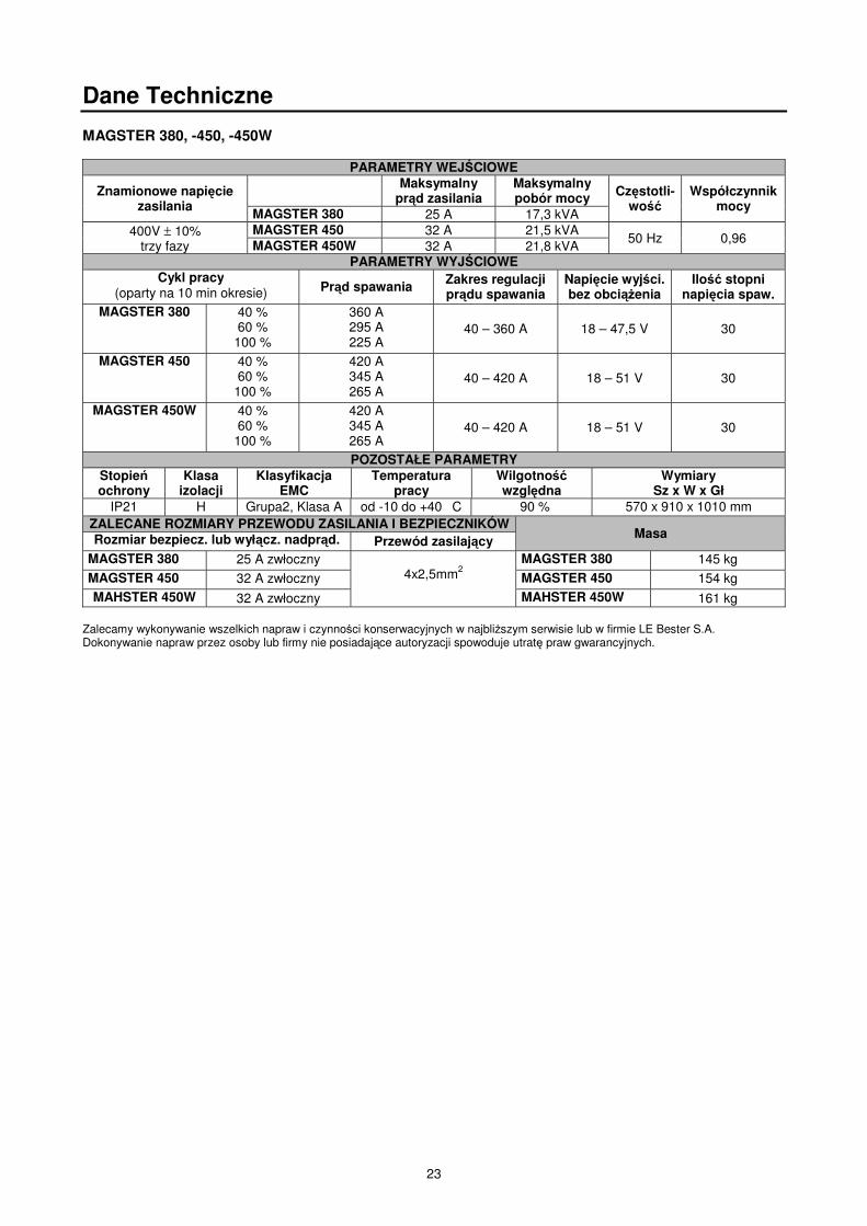
MAGSTER 380, -450, -450W
PARAMETRY WEJ CIOWE
Znamionowe napi ciezasilania
Maksymalnypr d zasilania
Maksymalnypobór mocy Cz stotli-
woWspółczynnik
mocyMAGSTER 380 25 A 17,3 kVA
400V ± 10%trzy fazy
MAGSTER 450 32 A 21,5 kVA50 Hz 0,96MAGSTER 450W 32 A 21,8 kVA
PARAMETRY WYJ CIOWECykl pracy
(oparty na 10 min okresie) Pr d spawania Zakres regulacjipr du spawania
Napi cie wyj ci.bez obci enia
Ilo stopninapi cia spaw.
MAGSTER 380 40 %60 %
100 %
360 A295 A225 A
40 – 360 A 18 – 47,5 V 30
MAGSTER 450 40 %60 %
100 %
420 A345 A265 A
40 – 420 A 18 – 51 V 30
MAGSTER 450W 40 %60 %
100 %
420 A345 A265 A
40 – 420 A 18 – 51 V 30
POZOSTAŁE PARAMETRYStopieochrony
Klasaizolacji
KlasyfikacjaEMC
Temperaturapracy
Wilgotnowzgl dna
WymiarySz x W x Gł
IP21 H Grupa2, Klasa A od -10 do +40 �C �90 % 570 x 910 x 1010 mmZALECANE ROZMIARY PRZEWODU ZASILANIA I BEZPIECZNIKÓW
MasaRozmiar bezpiecz. lub wył cz. nadpr d. Przewód zasilaj cyMAGSTER 380 25 A zwłoczny
4x2,5mm2MAGSTER 380 145 kg
MAGSTER 450 32 A zwłoczny MAGSTER 450 154 kgMAHSTER 450W 32 A zwłoczny MAHSTER 450W 161 kg
Zalecamy wykonywanie wszelkich napraw i czynno ci konserwacyjnych w najbli szym serwisie lub w firmie LE Bester S.A.Dokonywanie napraw przez osoby lub firmy nie posiadaj ce autoryzacji spowoduje utrat praw gwarancyjnych.

24
Spare Parts, Ersatzteile, Wykaz Cz ci Zamiennych10/08
Part List reading instructions• Do not use this part list for a machine if its code number is not listed. Contact the Lincoln Electric Service Department for
any code number not listed.• Use the illustration of assembly page and the table below to determine where the part is located for your particular code
machine.• Use only the the parts marked "x" in the column under the heading number called for in the assembly page (# indicate a
change in this printing).Hinweise zur Verwendung der Ersatzteillisten• Verwenden Sie diese Ersatzteilliste nicht für Geräte, nach deren code number diese Liste nicht gültig ist. Kontaktieren Sie
in diesem Fall die Ihnen bekannte Lincoln Service Station.• Bestimmen Sie mit Hilfe der assembly page, der Stückliste und der code number Ihres Geräts, an welcher Stelle sich das
jeweilige Ersatzteil befindet.• Ermitteln Sie zunächst mit Hilfe der assembly page die für die code number Ihres Geräts gültige Index-Spaltennummer,
und wählen Sie anschließend nur die Ersatzteile aus, die in dieser Spalte mit einem “X” markiert sind (das Zeichen #weist auf eine Änderung hin).
Wykaz cz ci dotycz cych instrukcji• Nie u ywa tej cz ci wykazu dla maszyn, których kodu (code) nie ma na li cie. Skontaktuj si z serwisem je eli numeru
kodu nie ma na li cie.• U yj ilustracji monta u (assembly page) i tabeli poni ej aby okresli poło enie cz ci dla urz dzenia z konkretnym kodem
(code).• U yj tylko cz ci z oznaczeniem “x” w kolumnie pod numerem głównym przywołuj cym stron (assembly page) z
indeksem modelu (# znajd zmiany na rysunku).

25
Spare Parts, Ersatzteile, Wykaz Cz ci Zamiennych

26
Spare Parts
Machine Code B NumberA Magster 380 1113 B18223-1B Magster 450 1114 B18224-1C Magster 450W 1115 B18225-1
Item Description Part Number A B C1 Quick Water Connector 21KATS09MPX (Q1, Q2) 0744-000-150R - - 22 Water Pump KN-23 Outlet 4 (M2) 0871-100-005R - - 13 Cooler (H) 0871-100-006R - - 14 Turning Wheel 125 KPS-PG 1029-660-127R 2 2 25 Wheel 250 SC250 1029-660-250R 2 2 26 Contactor CI-30 42VAC (K1) 1115-212-201R - 1 17 Contactor CI-25 42VAC (K1) 1115-212-202R 1 - -8 Voltage Switch ŁK40-5.8370 L14 (S2) 1115-260-073R 1 1 19 Voltage Switch ŁK40-6.12105 L14 (S1) 1115-260-074R 1 1 1
10 Mains Switch W4.8 400V (S3) 1115-270-019R 1 1 111 Mains Switch Guard 1115-299-073R 1 1 112 Rectifier Set PTS-400+T115 (V1) 1156-112-006R 1 - -13 Rectifier Set PTS-450+T115 (V1) 1156-112-007R - 1 114 Capacitor TC886 2uF (C4) 1158-121-001R 1 1 115 Line Filter type 43.0001.1018 (X7) 0874-400-011R 1 1 116 Fuse Base 1158-632-032R 3 3 317 Fuse Cap 1158-632-033R 3 3 318 Socket SZR16P2EG5 (X6) 1158-641-003R 1 1 119 Socket SZR28P7EG7 (X4) 1158-641-031R 1 1 120 Fuse Cartridge 3A 6,3x32 (F1) 1158-660-006R 1 1 121 Fuse Cartridge 6,3A 6,3x32 (F2) 1158-660-008R 1 1 122 Fuse Cartridge 4A 6,3x32 (F3) 1158-660-084R 1 1 123 Handle Boteco B226-180 M8 1361-598-186R 2 2 224 Carriage Support 1361-598-181R 1 1 125 Label 2719-107-130R 1 1 126 Welding Socket (X1, X2, X3) C-2986-001-3R 3 3 327 Auxiliary Transformer (T2) C-4244-296-2R 1 1 128 Lower Front Panel R-1019-103-1/08R 1 1 129 Top Panel R-1019-104-1/02R 1 1 -30 Upper Front Panel R-1019-107-1R 1 - -31 Upper Front Panel R-1019-107-2R - 1 -32 Upper Front Panel R-1019-107-3R - - 133 Right Bracket R-1019-108-1/08R 1 1 134 Right Bracket R-1019-109-1/08R 1 1 135 Rear Panel R-1019-113-1R 1 1 136 Right Side Panel R-1019-114-1R 1 1 -37 Right Side Panel R-1019-114-2R - - 138 Left Side Panel R-1019-119-1R 1 1 139 Fan Bracket R-3019-030-2/08R 1 1 140 Base Panel R-3019-090-1/08R 1 1 141 Shelf R-3019-091-1/08R 1 1 142 Top Panel R-3019-092-1/02R - - 143 Bracket R-3019-093-1/08R 1 1 144 Dividing Panel R-3019-094-1/08R 1 1 145 Choke (L1) R-4034-045-1R 1 - -46 Choke (L1) R-4034-047-1R - 1 147 Main Transformer (T1) R-4034-050-1R 1 - -48 Main Transformer (T1) R-4034-051-1R - 1 149 Mains Cord Without Plug R-5041-073-1R 1 1 150 Fan (M1) R-8040-055-2R 1 1 151 Reservoir Assembly (B) R-8040-147-2R - - 152 Fill Cap 1364-161-002R - - 153 Cooling System Looping Hose D-2218-150-1R - - 154 Cable Bushing Clamp 1361-599-398R 1 1 1
27
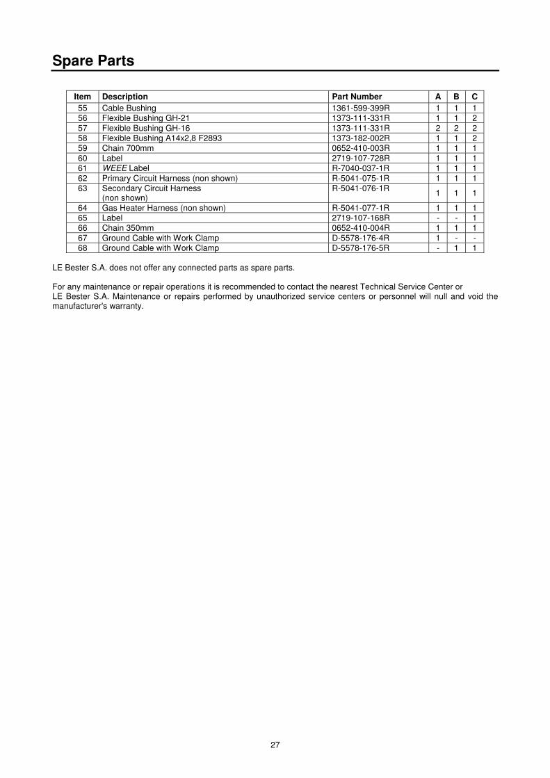
Spare Parts
Item Description Part Number A B C55 Cable Bushing 1361-599-399R 1 1 156 Flexible Bushing GH-21 1373-111-331R 1 1 257 Flexible Bushing GH-16 1373-111-331R 2 2 258 Flexible Bushing A14x2,8 F2893 1373-182-002R 1 1 259 Chain 700mm 0652-410-003R 1 1 160 Label 2719-107-728R 1 1 161 WEEE Label R-7040-037-1R 1 1 162 Primary Circuit Harness (non shown) R-5041-075-1R 1 1 163 Secondary Circuit Harness
(non shown)R-5041-076-1R 1 1 1
64 Gas Heater Harness (non shown) R-5041-077-1R 1 1 165 Label 2719-107-168R - - 166 Chain 350mm 0652-410-004R 1 1 167 Ground Cable with Work Clamp D-5578-176-4R 1 - -68 Ground Cable with Work Clamp D-5578-176-5R - 1 1
LE Bester S.A. does not offer any connected parts as spare parts.
For any maintenance or repair operations it is recommended to contact the nearest Technical Service Center orLE Bester S.A. Maintenance or repairs performed by unauthorized service centers or personnel will null and void themanufacturer's warranty.

28
Ersatzteile
Erzeugnis Code IndexA Magster 380 1113 B18223-1B Magster 450 1114 B18224-1C Magster 450W 1115 B18225-1
Pos. Beschreibung Index A B C1 Schnellbinder 21KATS09MPX (Q1, Q2) 0744-000-150R - - 22 Wasserpumpe KN-23 wyk.4 (M2) 0871-100-005R - - 13 Radiator (H) 0871-100-006R - - 14 Wenderad 125 KPS-PG 1029-660-127R 2 2 25 Rad 250 SC250 1029-660-250R 2 2 26 Schütz CI-30 42VAC (K1) 1115-212-201R - 1 17 Schütz CI-25 42VAC (K1) 1115-212-202R 1 - -8 Schalter ŁK40-5.8370 L14 (S2) 1115-260-073R 1 1 19 Schalter ŁK40-6.12105 L14 (S1) 1115-260-074R 1 1 110 Schalter W4.8 400V (S3) 1115-270-019R 1 1 111 Schutz 1115-299-073R 1 1 112 Gleichrichterbrücke V PTS-400+T115 (V1) 1156-112-006R 1 - -13 Gleichrichterbrücke V PTS-450+T115 (V1) 1156-112-007R - 1 114 Kondensatoren TC886 2uF (C4) 1158-121-001R 1 1 115 Störungsfilter Typ 43.0001.1018 (X7) 0874-400-011R 1 1 116 Sicherungssockel 1158-632-032R 3 3 317 Sockeldrehkapsel 1158-632-033R 3 3 318 Sicherungssockel SzR16P2EG5 (X6) 1158-641-003R 1 1 119 Busche SzR28P7EG7 (X4) 1158-641-031R 1 1 120 Sicherung 3A 6,3x32 (F1) 1158-660-006R 1 1 121 Sicherung 6,3A 6,3x32 (F2) 1158-660-008R 1 1 122 Sicherung 4A 6,3x32 (F3) 1158-660-084R 1 1 123 Griff Boteco B226-180 M8 1361-598-186R 2 2 224 Drehtragstein 1361-598-181R 1 1 125 Anklebezettel 2719-107-130R 1 1 126 Schweißbuchse (X1, X2, X3) C-2986-001-3R 3 3 327 Hilfstransformator (T2) C-4244-296-2R 1 1 128 Unterfrontplatte R-1019-103-1/08R 1 1 129 Deckel R-1019-104-1/02R 1 1 -30 Oberfrontplatte R-1019-107-1R 1 - -31 Oberfrontplatte R-1019-107-2R - 1 -32 Oberfrontplatte R-1019-107-3R - - 133 Tragstein recht R-1019-108-1/08R 1 1 134 Tragstein links R-1019-109-1/08R 1 1 135 Rückplatte R-1019-113-1R 1 1 136 Seitenplatte recht R-1019-114-1R 1 1 -37 Seitenplatte recht R-1019-114-2R - - 138 Seitenplatte links R-1019-119-1R 1 1 139 Ventilator Trennwand R-3019-030-2/08R 1 1 140 Grundlage R-3019-090-1/08R 1 1 141 Anlageregal R-3019-091-1/08R 1 1 142 Deckel R-3019-092-1/02R - - 143 Tragstein R-3019-093-1/08R 1 1 144 Trennwand R-3019-094-1/08R 1 1 145 Drossel (L1) R-4034-045-1R 1 - -46 Drossel (L1) R-4034-047-1R - 1 147 Haupttransformator (T1) R-4034-050-1R 1 - -48 Haupttransformator (T1) R-4034-051-1R - 1 149 Netzkabel R-5041-073-1R 1 1 150 Ventilator (M1) R-8040-055-2R 1 1 151 Behälter, komplett (B) R-8040-147-2R - - 152 Schraubenmutter 1364-161-002R - - 153 Klammer D-2218-150-1R - - 154 Kabeldurchführung Klemme 1361-599-398R 1 1 155 Kabeldurchführung 1361-599-399R 1 1 1

29
Ersatzteile
Pos. Beschreibung Index A B C56 Gummidurchlaß GH-21 1373-111-331R 1 1 257 Gummidurchlaß GH-16 1373-111-331R 2 2 258 Gummidurchlaß A14x2,8 F2893 1373-182-002R 1 1 259 Kette 700mm 0652-410-003R 1 1 160 Anklebezettel 2719-107-728R 1 1 161 Anklebezettel WEEE R-7040-037-1R 1 1 162 Hauptschaltkreis Bündel
(keine Abbildung)R-5041-075-1R 1 1 1
63 Sekundärschaltkreis Bündel(keine Abbildung)
R-5041-076-1R 1 1 1
64 Erwärmer Bündel(keine Abbildung)
R-5041-077-1R 1 1 1
65 Anklebezettel 2719-107-168R - - 166 Kette 350mm 0652-410-004R 1 1 167 Massekabel D-5578-176-4R 1 - -68 Massekabel D-5578-176-5R - 1 1
LE Bester S.A. empfehlt keine vereinigte Teilen als Ersatzteile.
Für Wartung und Reparatur des Gerätes konsultieren Sie bitte Ihren Fachhändler oder die LE Bester S.A. Eineunsachgemäß durchgeführte Wartung oder Reparatur durch eine nicht qualifizierte Person führt zum Erlöschen derGarantie. Die Reparaturen der Schweißanlagen und Ausrüstung sollen durch Qualifiziert Personen durchgeführt werden.

30
Wykaz Cz ci Zamiennych
Wyrób Code IndeksA Magster 380 1113 B18223-1B Magster 450 1114 B18224-1C Magster 450W 1115 B18225-1
Poz. Nazwa cz ci Indeks A B C1 Szybkozł czka 21KATS09MPX (Q1, Q2) 0744-000-150R - - 22 Pompa wodna KN-23 wyk.4 (M2) 0871-100-005R - - 13 Radiator (H) 0871-100-006R - - 14 Koło skr tne 125 KPS-PG 1029-660-127R 2 2 25 Koło 250 SC250 1029-660-250R 2 2 26 Stycznik CI-30 42VAC (K1) 1115-212-201R - 1 17 Stycznik CI-25 42VAC (K1) 1115-212-202R 1 - -8 Ł cznik ŁK40-5.8370 L14 (S2) 1115-260-073R 1 1 19 Ł cznik ŁK40-6.12105 L14 (S1) 1115-260-074R 1 1 110 Ł cznik W4.8 400V (S3) 1115-270-019R 1 1 111 Osłona 1115-299-073R 1 1 112 Mostek prostowniczy PTS-400+T115 (V1) 1156-112-006R 1 - -13 Mostek prostowniczy PTS-450+T115 (V1) 1156-112-007R - 1 114 Kondensator TC886 2uF (C4) 1158-121-001R 1 1 115 Filtr przeciwzakłóceniowy typ 43.0001.1018 (X7) 0874-400-011R 1 1 116 Gniazdo bezpiecznikowe 1158-632-032R 3 3 317 Zakr tka gniazda 1158-632-033R 3 3 318 Gniazdo SzR16P2EG5 (X6) 1158-641-003R 1 1 119 Gniazdo SzR28P7EG7 (X4) 1158-641-031R 1 1 120 Wkładka topikowa 3A 6,3x32 (F1) 1158-660-006R 1 1 121 Wkładka topikowa 6,3A 6,3x32 (F2) 1158-660-008R 1 1 122 Wkładka topikowa 4A 6,3x32 (F3) 1158-660-084R 1 1 123 Uchwyt Boteco B226-180 M8 1361-598-186R 2 2 224 Wspornik obrotowy 1361-598-181R 1 1 125 Nalepka 2719-107-130R 1 1 126 Gniazdo spawalnicze (X1, X2, X3) C-2986-001-3R 3 3 327 Transformator pomocniczy (T2) C-4244-296-2R 1 1 128 Płyta przednia dolna R-1019-103-1/08R 1 1 129 Pokrywa R-1019-104-1/02R 1 1 -30 Płyta przednia górna R-1019-107-1R 1 - -31 Płyta przednia górna R-1019-107-2R - 1 -32 Płyta przednia górna R-1019-107-3R - - 133 Wspornik prawy R-1019-108-1/08R 1 1 134 Wspornik lewy R-1019-109-1/08R 1 1 135 Płyta tylna R-1019-113-1R 1 1 136 Płyta boczna prawa R-1019-114-1R 1 1 -37 Płyta boczna prawa R-1019-114-2R - - 138 Płyta boczna lewa R-1019-119-1R 1 1 139 Przegroda wentylatora R-3019-030-2/08R 1 1 140 Podstawa R-3019-090-1/08R 1 1 141 Półka R-3019-091-1/08R 1 1 142 Pokrywa R-3019-092-1/02R - - 143 Wspornik R-3019-093-1/08R 1 1 144 Przegroda R-3019-094-1/08R 1 1 145 Dławik (L1) R-4034-045-1R 1 - -46 Dławik (L1) R-4034-047-1R - 1 147 Transformator główny (T1) R-4034-050-1R 1 - -48 Transformator główny (T1) R-4034-051-1R - 1 149 Przewód sieciowy R-5041-073-1R 1 1 150 Wentylator (M1) R-8040-055-2R 1 1 151 Zbiornik kompletny (B) R-8040-147-2R - - 152 Nakr tka 1364-161-002R - - 153 Zwora D-2218-150-1R - - 154 Zacisk przepustu kablowego 1361-599-398R 1 1 155 Przepust kablowy 1361-599-399R 1 1 1

31
Wykaz Cz ci Zamiennych
Poz. Nazwa cz ci Indeks A B C56 Przelotka gumowa GH-21 1373-111-331R 1 1 257 Przelotka gumowa GH-16 1373-111-331R 2 2 258 Przelotka gumowa A14x2,8 F2893 1373-182-002R 1 1 259 Ła cuch 700mm 0652-410-003R 1 1 160 Nalepka 2719-107-728R 1 1 161 Nalepka WEEE R-7040-037-1R 1 1 162 Wi zka obwodu pierwotnego
(nie pokazano na rysunku)R-5041-075-1R 1 1 1
63 Wi zka obwodu wtórnego(nie pokazano na rysunku)
R-5041-076-1R 1 1 1
64 Wi zka podgrzewacza(nie pokazano na rysunku)
R-5041-077-1R 1 1 1
65 Nalepka 2719-107-168R - - 166 Ła cuch 350mm 0652-410-004R 1 1 167 Przewód masowy D-5578-176-4R 1 - -68 Przewód masowy D-5578-176-5R - 1 1
Firma LE Bester S.A. nie oferuje cz ci zł cznych jako cz ci zamiennych.
W sprawach obsługi serwisowej i napraw nale y kontaktowa si z najbli szym autoryzowanym punktem serwisowymLE Bester S.A.. Obsługa serwisowa i naprawy przeprowadzane przez nieautoryzowane punkty serwisowe powodujutrat uprawnie z tytułu gwarancji. Naprawy urz dze i osprz tu spawalniczego powinny by wykonywane przez osobyo odpowiednich kwalifikacjach.

32
Electrical Schematic, Elektrische Schaltpläne, Schemat Elektryczny
Electrical Schematic / Elektrische Schaltpläne /Schemat elektryczny

33
Electrical Schematic, Elektrische Schaltpläne, Schemat Elektryczny
Power Source – Wire Feeder Connection / Stromquelle - SchweißdrahtaufgeberVerbindung / Pł czenie ródło pr du – podajnik drutu

34
Electrical Schematic, Elektrische Schaltpläne, Schemat Elektryczny
Cooling System Schematic (Magster 450W only) / Kühlanlage Schaltkreis (nurMagster 450W) / Schemat układu chłodzenia (tylko Magster 450W)

35
Accessories, Zubehör, Akcesoria
Machine/Erzeugnis/WyróbA Magster 380B Magster 450C Magster 450W
Item Description Part Number A B C1 Interconnection Cable (Air) PZ-380-450-5M B10357-1 + + -2 Interconnection Cable (Air) PZ-380-450-10M B10357-2 + + -3 Interconnection Cable (Air) PZ-380-450-15M B10357-3 + + -4 Interconnection Cable (Air) PZ-380-450-20M B10357-4 + + -5 Interconnection Cable (Water) PZW-380-450-5M B10356-1 - - +6 Interconnection Cable (Water) PZW-380-450-10M B10356-2 - - +7 Interconnection Cable (Water) PZW-380-450-15M B10356-3 - - +8 Interconnection Cable (Water) PZW-380-450-20M B10356-4 - - +9 Coolant Acorox 2x5l K10420-1 - - +
Pos. Beschreibung Ersatzteil-Nr. A B C1 Zuleitungspaket ( Luft ) PZ-380-450-5M B10357-1 + + -2 Zuleitungspaket ( Luft ) PZ-380-450-10M B10357-2 + + -3 Zuleitungspaket ( Luft ) PZ-380-450-15M B10357-3 + + -4 Zuleitungspaket ( Luft ) PZ-380-450-20M B10357-4 + + -5 Zuleitungspaket (Wasser) PZW-380-450-5M B10356-1 - - +6 Zuleitungspaket (Wasser) PZW-380-450-10M B10356-2 - - +7 Zuleitungspaket (Wasser) PZW-380-450-15M B10356-3 - - +8 Zuleitungspaket (Wasser) PZW-380-450-20M B10356-4 - - +9 Kühlfussigkeit Acorox 2x5l K10420-1 - - +
Poz. Nazwa cz ci Indeks A B C1 Przewód zespolony PZ-380-450-5M B10357-1 + + -2 Przewód zespolony PZ-380-450-10M B10357-2 + + -3 Przewód zespolony PZ-380-450-15M B10357-3 + + -4 Przewód zespolony PZ-380-450-20M B10357-4 + + -5 Przewód zespolony wodny PZW-380-450-5M B10356-1 - - +6 Przewód zespolony wodny PZW-380-450-10M B10356-2 - - +7 Przewód zespolony wodny PZW-380-450-15M B10356-3 - - +8 Przewód zespolony wodny PZW-380-450-20M B10356-4 - - +9 Płyn chłodniczy Acorox 2x5l K10420-1 - - +

36
WEEE

37
WEEE
RECYCLE ST
REF. FE AL CU
BR
AS
S
BO
AR
DS
PLA
ST
ICS
LIQU
IDC
RIS
TA
L
EX
TE
RN
AL
ELE
CT
RIC
CA
BLE
S
CA
PA
CIT
OR
S
TOP PANEL 1 XPUMP 2 X X X XRIGHT SIDE PANEL 3 XBRACKET 4, 18 XRESERVOIR 5 XHANDLE 6 X XMAINS SWITCH 7 X XSWITCH 8, 9 X XUPPER FRONT PANEL 10 X XLOWER FRONT PANEL 11 XWELDING SOCKET 12 X XCONTROL SOCKET 13 X X XQUICK WATER CONNECTOR 14 XCOOLER 15 X X XRECTIFIER SET 16 X X X XCHOKE 17 X X X XTURNING WHEEL 19 X XCAPACITOR 20, 36 XFAN BRACKET 21 XBASE PANEL 22 XFAN 23 X X XTRANSFORMERS 24, 32 X X XWHEEL 25 XLEFT SIDE PANEL 26 XMAINS CORD 27 XFUSE 28 X XGAS HEATER SOCKET 29 X X XREAR PANEL 30 XSHELF 31 X XDIVIDING PANEL 33 X XCONTACTOR 34 X X XBRACKET 35 X

38
WEEE
RÜCKGEWINNUNG ST
Ref. Fe Al Cu
ME
SS
ING
ELR
KT
RIS
CH
EP
LAT
TE
N
KU
NS
TS
TO
FF
E
LCD
AN
ZE
IGE
ÄU
ßE
RLIC
HE
LEIT
UN
GE
N
KO
ND
EN
SA
-T
OR
EN
DECKEL 1 XPUMPE 2 X X X XSEITEN PLATTE RECHT 3 XTRAGSTEIN 4, 18 XBEHÄLTER 5 XGRIFF 6 X XNETZSCHALTER 7 X XSCHALTER 8, 9 X XOBERFRONTPLATTE 10 X XUNTERFRONTPLATTE 11 XSCHWEIßBUCHSE 12 X XSTEUERBUCHSE 13 X X XSCHNELLBINDER 14 XRADIATOR 15 X X XGLEICHRICHTERBRÜCKE 16 X X X XDROSSEL 17 X X X XWENDERAD 19 X XKONDENSATOR 20, 36 XVENTILATOR TRENNWAND 21 XGRUNDLAGE 22 XVENTILATOR 23 X X XTRANSFORMATOR 24, 32 X X XRAD 25 XSEITEN PLATTE LINKS 26 XVERSORGUNGSLEITER 27 XSICHERUNGSSOCKEL 28 X XVORWÄRMERBUCHSE 29 X X XRÜCKPLATTE 30 XANLAGEREGAL 31 X XTRENNWAND 33 X XSCHÜTZ 34 X X XTRAGSTEIN 35 X

39
WEEE
RECYCLE ST
REF. FE AL CU
MO
SI
DZ
PŁY
TK
IE
LEK
TR
ON
ICZ
NE
TW
OR
ZY
WA
SZ
TU
CZ
NE
WY
WIE
TLA
CZ
ELC
D
PR
ZE
WO
DY
ZE
WN
TR
ZN
E
KO
ND
EN
SA
TO
RY
POKRYWA 1 XPOMPA 2 X X X XPŁYTA BOCZNA PRAWA 3 XWSPORNIK 4, 18 XZBIORNIK 5 XUCHWYT 6 X XŁ CZNIK SIECIOWY 7 X XŁ CZNIK 8, 9 X XPŁYTA PRZEDNIA GÓRNA 10 X XPŁYTA PRZEDNIA DOLNA 11 XGNIAZDO SPAWALNICZE 12 X XGNIAZDO STEROWANIA 13 X X XSZYBKOZŁ CZKA 14 XRADIATOR 15 X X XMOSTEK PROSTOWNICZY 16 X X X XDŁAWIK 17 X X X XKOŁO SKR TNE 19 X XKONDENSATOR 20, 36 XPRZEGRODA WENTYLATORA 21 XPODSTAWA 22 XWENTYLATOR 23 X X XTRANSFORMATOR 24, 32 X X XKOŁO 25 XPŁYTA BOCZNA LEWA 26 XPRZEWÓD ZASILAJ CY 27 XGNIAZDA BEZPIECZNIKÓW 28 X XGNIAZDO PODGRZEWACZA 29 X X XPŁYTA TYLNA 30 XPÓŁKA 31 X XPRZEGRODA 33 X XSTYCZNIK 34 X X XWSPORNIK 35 X

40
MANUAL REVISIONS
DO NOT PRINT THIS PAGE IN THE MANUAL.
REV 0:• Beta phase Manual English / German / Polish.
PRINT THIS MANUAL ACCORDINGLY WITH THE PROCEDURE DT0052.