Embed Size (px)
Citation preview
COCOON AQUA IR
HYDRATION PRO
OWNER’S MANUAL
CAH.10.0818.1.U

TABLE OF CONTENTS TABLE OF CONTENTS Page Section 1 Introduction 1.1 Purpose of the Manual 1 1.2 Customer Service 1 1.3 Disclaimer 1 1.4 Copyright 2
Section 2 Safety 2.1 Pre-installation Technical Safety Tips 3 2.2 General and User Safety 3 2.3 Safety Precautions 4 Section 3 Shipping, Storing and Installation Conditions 3.1 Shipping, Storing and Installation Conditions 5 3.2 Oxygen Connection (optional; oxygen unit not included) 5 Section 4 Electrical Requirements 4.1 Electrical Installation Requirements 6 Section 5 Product Introduction 5.1 Cocoon Aqua IR Hydration Pro System Introduction 7 5.2 Cocoon Aqua IR Hydration Pro System Features 7 5.3 Cocoon Aqua IR Hydration Pro System Contraindications 8 Section 6 Installation 6.1 Removing Side Panels 9 6.2 Installing the Hood 9 6.3 Adjusting the Legs 13 6.4 Cocoon Aqua IR Hydration Pro Installation Instructions 14 6.5 Installing Side Panels 16 6.6 Installing the Hood Cover 17 6.7 Water Supply 17 6.8 Installing the Pedestal 19 6.9 Installation Test 20 Section 7 Operation 7.1 The Control Panel(s) 21 7.2 Preparation for Operation 21 7.3 Automatic Warm-Up Functions _____________________________ 21 7.4 Initial or Automatic “Warm-Up” Session 23 7.5 Working with the Options 23 7.6 Operations: Selecting a Program 24
TABLE OF CONTENTS (Continued)
7.7 Adjusting Features with a Selected Pre-Program 24 7.8 Safety Shut Off: Lifting the Hood During a Session _____________ 27 7.9 Stopping Your Session 27 7.10 Turning Off Your Cocoon Aqua IR Hydration Pro System 27 Section 8 Service (Hood) 8.1 Removing the Hood Cover 28 8.2 Removing the Hood and Changing the Strut Nut 28 8.3 Heat Emitter 29 8.4 Speaker 30 8.5 Temperature Sensor 31 8.6 Opening the LCD Housing 31 8.7 Replacing Parts in the LCD Housing 32 Section 9 Service (Bottom) 9.1 Removing Side Panels 35 9.2 Drainage 35 9.3 On-off Switch 36 9.4 Aroma System 36 9.5 Vibratory Bed 37 9.6 Hood Switch 38 9.7 Supply Transformers 38 9.8 Steam Generator 39 9.9 Replacing the Heating Element 39 9.10 Replacing the Thermal Fuse 40 9.11 Replacing the Water Level Sensor 40 Section 10 Advanced Electronics and Troubleshooting 10.1 Electrical Connections 42 10.2 Other Components on the PC Board 43 10.3 Troubleshooting 44 Section 11 System Cleaning, Maintenance and Reinstallation 11.1 General Cleaning and Mandatory Use of Pre-Approved Solution 46 11.2 Cleaning the Shell 47 11.3 Cleaning the Underbed Area 47 11.4 Cleaning Contact Surfaces (Bed, Head Pillow, Interior of Shell) 48 11.5 Cleaning the Steam Generator 48 11.6 Cleaning the Aroma/Liquid Concentrate Diffusion System 49 11.7 Cleaning the System Drain 50 11.8 Annual Maintenance and Periodic Inspections 50

TABLE OF CONTENTS (Continued)
Section 12 Specification Information 12.1 General 52 12.2 Supplied Accessories 53 APPENDICES Owner Record A Owner’s Registration Form B Standard Warranty C Cocoon Aqua IR Hydration Pro Programs F

Section 1 Introduction
Cocoon Aqua IR Hydration Pro System 1
SECTION 1: INTRODUCTION
1.1 Purpose of the Manual This manual explains how to correctly install, operate, and get the best performance from your Cocoon Aqua IR Hydration Pro System. It may be used as a guide, suitable for all levels of technical expertise, in determining and servicing mechanical and electrical difficulties. This owner’s manual is organized as a quick reference guide. Any additional updated or supplemental information for this reference guide may be distributed to you as needed. Please read this owner's manual carefully before installing your machine. Keep your manual near your machine for quick reference.
1.2 Customer Service We welcome and appreciate your comments, questions, and suggestions in order to continually offer the highest quality products, accessories, and services to our customers. Our qualified professional teams are ready to assist you with a prompt response to any question that you might have.
1.3 Disclaimer While every attempt is made to ensure the accuracy and completeness of the information in this document, some errors may exist. NuAge Beauty, Inc. does not accept responsibility of any kind for customer loss due to use of or reliance upon this document. NuAge Beauty reserves the right to make changes without notice in the product described or contained herein in order to improve design and/or performance. NuAge Beauty assumes no responsibility or liability for the use of the product, conveys no license or title under any patent, copyright, or trademark right to this product or processes and makes no representation or warranty that this product is free from patent, copyright, or trademark right infringement, unless otherwise specified. Applications that are described herein for the product are for illustrative purposes only. NuAge Beauty makes no representation or warranty that such applications are suitable for the specified use without further testing or modification.
Section 1 Introduction
Cocoon Aqua IR Hydration Pro System 3
1.4 Copyright This manual is protected by copyrights. All rights are reserved. No part of this publication may be reproduced, stored in a retrieval system, or transmitted in any form or by any means: electronic, mechanical, photocopying, recording, or otherwise without the prior written permission from the author and publisher. All inquiries should be addressed to distributor at the address listed on the appendices of this manual, along with a date from a copy of the original purchase receipt of the Cocoon Aqua IR Hydration Pro System. No attempt has been made to designate as trademarks or service marks all words or terms in which proprietary rights might exist. The inclusion, exclusion, or definition of a word or term is not intended to affect, or to express a judgment on, the validity or legal status of the word or term as a trademark, service mark, or other proprietary term.

Section 2 Safety
Cocoon Aqua IR Hydration Pro System 3
SECTION 2: SAFETY
2.1 Pre-installation Technical Safety Tips
Attention: When receiving a packed Cocoon Aqua IR Hydration Pro shipment transported in winter conditions (transportation temperature below 32°F [0°C]), the unit must be stored at room temperature (conditions +59 to +86°F [+15 to +30°C], relative humidity max. 95%) for twenty-four hours to be warmed up before installation and operation. Installing the unit and starting the unit prematurely (without prior slow warming period) may result in serious damage to the electronics and LCD panel of the unit.
Only a qualified/certified/licensed electrician is authorized to make the electrical corrections strictly according to all local electrical installation requirements. Any unauthorized and/or improper electrical installation is strictly forbidden. In case of unauthorized and/or improper installation, this unit must not be used and it will result in waive of any type manufacture’s warranty.
The use and operation of the unit must be ceased immediately if, after installation, the unit does not operate properly.
2.2 General and User Safety
In order to guarantee full user safety, this unit must be installed according to the requirements of this installation manual and in compliance with all local electrical requirements and with other applicable standards. (See the Electrical Installation Requirements in Section 4.)
In order to guarantee full user safety and reduce any type of risk or injury, this unit must at all times be operated under the full supervision and assistance of a trained qualified assistant; children are prohibited to use this unit without a trained, qualified assistant.
Pregnant women and/or person having a medical condition and/or using medication, and/or having adverse medical history should not use this unit unless recommended by a physician.
In order to guarantee user safety and comfort, this unit must be technically inspected daily and thoroughly cleaned and disinfected before every use. All unit operations, technical inspection, and cleaning must be done by trained, qualified personnel.

Section 2 Safety
Cocoon Aqua IR Hydration Pro System 4
2.3 Safety Precautions
Check the unit’s operating voltage before operation. It must be identical with that of your local power supply.
When using any setting of Radiant Heat with the Cocoon Aqua IR Hydration Pro System, be sure to refrain from touching the upper portion of the inside of the cabinet. The radiant emitters are located in this area and become very hot when the Radiant Heat feature is in use.
Do not disassemble or modify the unit.
Prevent flammables and metallic objects from entering the unit.
Do not use the unit when there is lightning in the vicinity.
Avoid using the unit under the following conditions: Places subject to excessive shock or vibration.
Extremely hot places.
Use carefully. May cause burns.
Do not sit on top of the cover.
Do not sit on the unit when cover is only half open or closed. Read this manual carefully before using the Cocoon Aqua IR Hydration Pro System.
NOTE: The rating plate (serial number plate) and safety caution of the main unit are located at the base of the machine on the lower right leg.

Section 3 Shipping, Storing, and Installation Conditions
Cocoon Aqua IR Hydration Pro System 5
SECTION 3: SHIPPING, STORING AND INSTALLATION CONDITIONS
3.1 Shipping, Storing and Installation Conditions
This unit is designed for permanent indoor installation with the following conditions: a. Temperature of the room: +59 to +86°F (+15 to +30°C). Relative humidity max. 85%. b. Shipping conditions: temperature -4 to 104°F (–20 to + 40°C). c. Storing conditions: temperature -4 to 104°F (–20 to +40°C). Relative humidity max. 95%.
Attention: When receiving a shipment transported in winter conditions (transportation temperature below 32°F [0°C]), The unit must be stored at room temperature (conditions +59 to +86°F [+15 to +30°C], relative humidity max. 95%), for twenty-four hours to be warmed up before installation and operation. Installing the unit and starting up the unit prematurely (without prior slow warming period) may result in serious damage to the electronics and LCD panel of the unit.
The unit must be installed on an even, dry, solid floor surface and levelled.
It is best if the room has a separate ventilation system guaranteeing the sufficient fresh air supply to the room.
3.2 Oxygen Connection (optional; oxygen unit not included)
1. To be compatible with the Cocoon Aqua IR Hydration Pro System, the plastic tube connecting the oxygen unit to the capsule must be ¼” inside diameter, ½” outside diameter.
2. Place oxygen unit within 3-4 feet of the head end of the Cocoon Aqua IR Hydration Pro unit.
3. Using appropriate germicidal solution, sanitize the plastic tube fitting that connects from the oxygen unit to the capsule and the oxygen input fitting of the Cocoon Aqua IR Hydration Pro unit, located at the head end of the unit, beneath the headrest area. When dry, connect the plastic tube to the input fitting on the Cocoon Aqua IR Hydration Pro unit.
4. TURN OXYGEN UNIT POWER SWITCH OFF AFTER TESTING OR USAGE.

Section 4 Electrical Requirements
Cocoon Aqua IR Hydration Pro System 6
SECTION 4: ELECTRICAL REQUIREMENTS
4.1 Electrical Installation Requirements NOTE: Only a qualified/certified/licensed electrician is authorized to make the electrical connections/installation of this unit strictly according to all local electrical installation requirements.
The unit’s power supply must be shut off prior to installation and/or any work on the unit.
The Cocoon Aqua IR Hydration Pro System should be used with AC 220, 50/60 Hz.
CAUTION: To prevent electric shocks and fire hazards, do NOT use any other power source.
Because of the special nature of this device, an entire circuit needs to be dedicated to the operation of the Cocoon Aqua IR Hydration Pro System. Each individual Cocoon Aqua IR Hydration Pro System should have its own dedicated circuit breaker. The current draw depends on the voltage and is rated at 13.41 amps for 220 volts when Radiant Heat and Steam are running.
The unit is designed for use in current circuits where either a neutral conductor or a stationary protective conductor with equivalent potential is available — system TN-S. It is strictly prohibited to use the unit in alternating current circuits TT and IT.
Unit electrical specifications: 13A, 220-240V, 50/60Hz.
For electrical installation, the right hand side panel of the unit must be removed.
Place the unit on a level surface.
Make sure the cover can be opened without hitting the ceiling. Check the SPECIFICATIONS SECTION for more details of the dimensions.
Do not install the unit near heat sources such as radiators, or in places subject to excessive dust, mechanical vibration, shock or heat.
Do not block the air inlet of the face fan located on top of the unit (hood).
If the unit is located in a cold location, the supporting hood strut may decrease pressure in the strut chambers, which may cause the hood to drop sharply. The operating temperature range for the struts is from 15 to 80°C or 50 to 180°F.
The unit must be connected to the electricity system stationary according to the following:

Section 5 Product Introduction
Cocoon Aqua IR Hydration Pro System 7
SECTION 5: PRODUCT INTRODUCTION
5.1 Cocoon Aqua IR Hydration Pro System Introduction With a mere 5- minute warm up time, the Cocoon Aqua IR Hydration Pro System will greatly enhance your ability to gain additional customers and increase revenue. Following is a list of the features of the innovative Cocoon Aqua IR Hydration Pro System.
5.2 Cocoon Aqua IR Hydration Pro System Features The features of your Cocoon Aqua IR Hydration Pro are listed below. We have created preset programs for ease-of-use and maximum efficiency; each program offers a different blend of Cocoon Aqua IR Hydration Pro features to your clients. To maximize versatility and creativity for salon/spa owners, a custom program is also available for you and/or your clients to create unique combinations of the Cocoon Aqua IR Hydration Pro features (see Appendix D for details on the preset programs.)
Radiant heat
Steam heat
Vibratory bed
Color lights
Aroma/Liquid Concentrates Product Diffusion
Audio ready
Face air Other standard features/accessories of the Cocoon Aqua IR Hydration Pro System:
DIGITAL CONTROL PANEL Sophisticated electronics are combined with a simple mechanical design to produce a technologically advanced machine. All of the Cocoon Aqua IR Hydration Pro System’s features are controllable at the touch of your fingertips. You can easily set and re-adjust any of the settings from inside the unit via the control panel. The controls are effortlessly monitored by means of a convenient LCD display. ERGONOMICALLY-DESIGNED CUSTOM CONTOUR BED The vibratory bed is contoured to the most comfortable fit for your body. No pressure points exist and cushioned support produces the feeling of relaxed flotation and air suspension.

Section 5 Product Introduction
Cocoon Aqua IR Hydration Pro System 8
5.3 Cocoon Aqua IR Hydration Pro System Contraindications
Knowledge of your client’s contraindications requires a thorough client analysis. Being unaware of their medical history may cause problems.
Heart/respiratory problems
High blood pressure
Kidney disorders
Nervous conditions (e.g. epilepsy)
Pregnancy
Open lesions
Pustules or cysts
Shellfish allergies The above conditions do not necessarily mean the client cannot receive the Cocoon Aqua IR Hydration Pro System sessions; however, it is recommended that they receive medical endorsement prior to seeking sessions.
1. DIGITAL CONTROL PANEL

Section 6 Installation
Cocoon Aqua IR Hydration Pro System 9
SECTION 6: INSTALLATION
Installation Steps (see the following detailed instructions per step):
6.1 Remove Side Panels 6.2 Install the Hood 6.3 Adjust the Legs
6.4 Connect Electrical Supply (to be done by qualified/certified/licensed electrician only) 6.5 Reattach Side Panels 6.6 Install Hood Cover NOTE: For reference, the use of “left” and “right” when referring to the machine will be done as if one is in the unit.
6.1 Removing Side Panels
Before any repair and/or inspection of the unit, the electrical supply must be shut off.
Before removing the side panel of the unit, shut off the electrical supply to the unit.
Tools/Supplies required: Phillips Head screwdriver, flat head screwdriver, 2 people
Removal (remove the right side panel first): a. Use a small flat head screwdriver to gently remove the white plastic caps over
the 10 screws. There are 3 on each end and 2 on each side. b. Use the Phillips Head screwdriver to remove the 10 screws. c. While another person slightly lifts the front of the machine, carefully remove the
right side panel by gently pulling down and outward on the right panel.
d) Remove the left panel in the same manner.
6.2 Installing the Hood Tools/Supplies required: 13mm wrench, 10mm wrench, 8mm wrench, 5 wire ties, Wire snips

Section 6 Installation
Cocoon Aqua IR Hydration Pro System 10
1) Ensure the three 13mm nuts are sufficiently loose to allow the hinge plate to slide
underneath. See Picture 1 and 2.

Section 6 Installation
Cocoon Aqua IR Hydration Pro System 11
2) Position the hood so the three grooves in the hinge plate shown in Picture 2 are aligned with the three 13mm screws/nuts. Slide the hood forward so the hinge plate slides under the three 13mm nuts and the two 10mm screws are also in their groove (See Picture 3).
Section 6 Installation
Cocoon Aqua IR Hydration Pro System 12
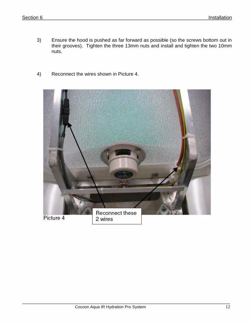
3) Ensure the hood is pushed as far forward as possible (so the screws bottom out in their grooves). Tighten the three 13mm nuts and install and tighten the two 10mm nuts.
4) Reconnect the wires shown in Picture 4.

Section 6 Installation
Cocoon Aqua IR Hydration Pro System 13
5.) Reconnect the wires shown in Picture 5.
6) The wires that were reconnected in Steps 4 and 5 have to be attached to the
aluminum frame via wire ties. Notice 5 black marks on the aluminum frame – these marks indicate the position where wire ties need to be installed to attach the wires to the aluminum frame. Snip the excess plastic off the wire tie after tightening to the aluminum frame.
6.3 Adjusting the Legs
This unit must be installed on an even, dry surface and levelled by adjusting the unit legs.
Loosen nut 2.
Regulate height by adjusting nut 3 (nut 1 must be held while adjusting).
If the position is correct, tighten nut 2.
If unable to hold nut 1 with a wrench, use a wedge (example screwdriver).

Section 6 Installation
Cocoon Aqua IR Hydration Pro System 14
6.4 Cocoon Aqua IR Hydration Pro Installation Instructions
1. Install hood as indicated in the hood installation instructions. 2. Locate the group of wires pictured below under the unit. 3. Plug the 220V 15 amp (NEMA 6-15) connector into the receptacle (Not supplied)
that was installed by an electrician in the customer’s wall (or) buck booster. 4. Route the small white wire up the wall into the double outlet box (Not supplied) that
was installed by the customer’s electrician. 5. Connect the two wires to the J3 contact located on the back of the supplied T Max
3A timer.

Section 6 Installation
Cocoon Aqua IR Hydration Pro System 15

Section 6 Installation
Cocoon Aqua IR Hydration Pro System 16
6.5 Installing Side Panels
2 Tools/Supplies required: Phillips Head screwdriver, flat head screwdriver, 2 people
Installation (install the left side panel first): a. Start by positioning the bottom of the left side panel slightly under the
machine. b. Position the top of the panel as close to the final position as possible. c. While another person slightly lifts the machine, push down gently along the
top of the panel in order for the lip of the side panel to go behind the lip of the bed base. See photo below.
d. At the head of the unit, be sure that the lip of the side panel fits in between the lip of the bed base and the metal rectangular guide. See photo below.
Section 6 Installation
Cocoon Aqua IR Hydration Pro System 17
e. Use the Phillips Head screwdriver to reinstall the 2 screws at the bottom of the left panel.
f. Install the right side panel in the same manner as the left one. g. Use the Phillips Head screwdriver to install the remaining 6 screws for the
head and the foot of the machine. h. Push the screw covers gently back on to cover the screws.
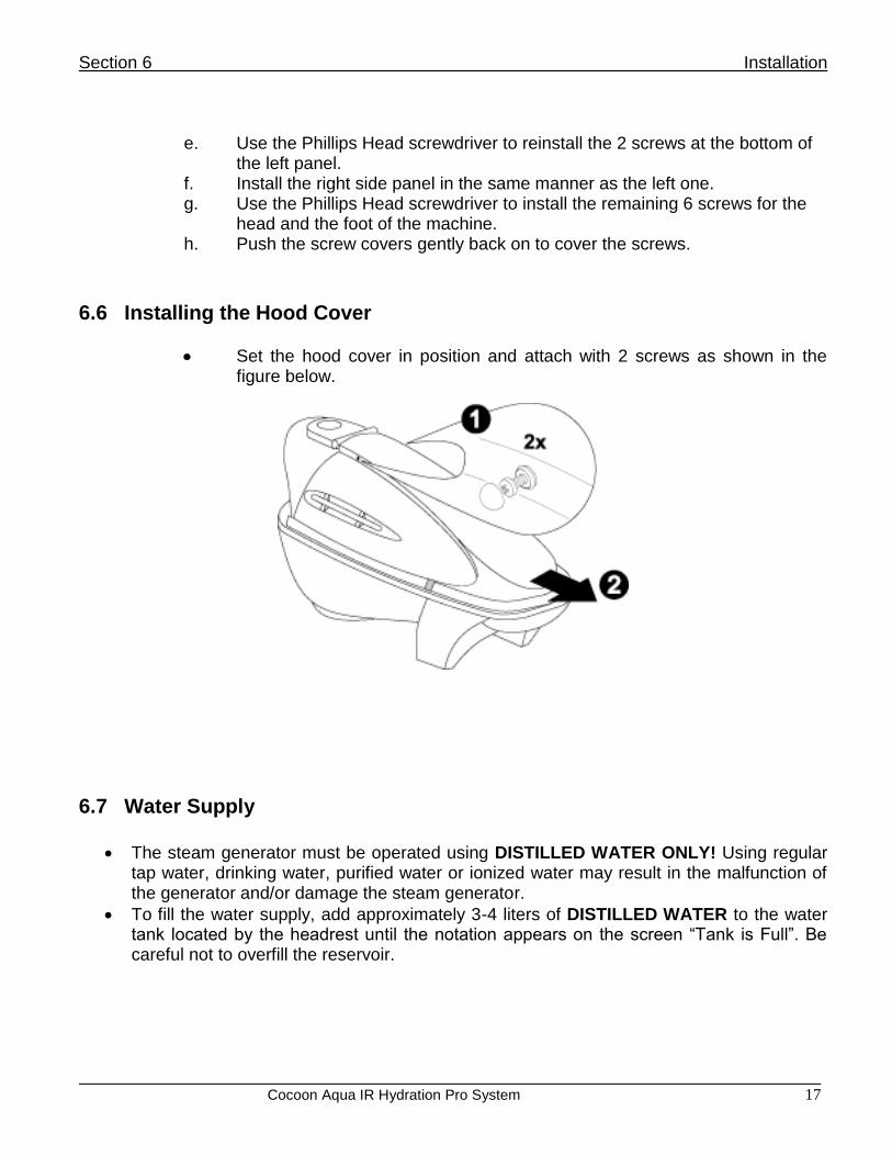
6.6 Installing the Hood Cover
Set the hood cover in position and attach with 2 screws as shown in the figure below.
6.7 Water Supply
The steam generator must be operated using DISTILLED WATER ONLY! Using regular tap water, drinking water, purified water or ionized water may result in the malfunction of the generator and/or damage the steam generator.
To fill the water supply, add approximately 3-4 liters of DISTILLED WATER to the water tank located by the headrest until the notation appears on the screen “Tank is Full”. Be careful not to overfill the reservoir.

Section 6 Installation
Cocoon Aqua IR Hydration Pro System 18
Figures A and B are possible variants to drain the capsule. You can use a water pan to collect water from condensation or connect capsule drainage. NOTE: Condensate pumps offer another drainage option and are available at your local hardware store. A sensor determines the water level at which to turn the pump on. The pump diverts the accumulated water from the pump reservoir and through a hose leading to a drain. They will require 120V and 1.5 to 2 gallons per minute pump capacity.

Section 6 Installation
Cocoon Aqua IR Hydration Pro System 19
6.8 Installing the Pedestal Tools/Supplies required: 1 adjustable wrench, 1 tape measure, 1 3-foot level (optional), and 2 people
Installation Steps
1. Insert the 8 adjustable feet (provided) into the mounting brackets of the pedestal frames (4 in each frame, see Figure 1)
2. Adjust the height of the feet so that all feet will contact the floor and the edges of the pedestal will NOT contact the floor (See Figure 2). Pedestal surface should be level.
3. When pedestal is level, turn it over again and use a wrench to adjust the nut on the stud of the adjustable foot firmly against the frame to lock the foot into place.
4. After the pedestal feet are mounted and correctly adjusted, check the feet of the Cocoon Aqua IR Hydration Pro to see that:
a. The feet are protruding sufficiently from the frame to inset comfortably on the pedestal surface (bottom of foot pad should be approximately 2.0 inches from bottom of the frame)
b. The feet are set appropriately so the Cocoon Aqua IR Hydration Pro System is balanced and level on the floor.
c. A wrench is used to adjust the nut on the stud of the adjustable foot firmly against the frame to lock the foot into place.
After all feet are adjusted and firmly installed:
5. Place all the pedestal sections on the floor in the position desired for system location. There should be approximately 15-16 inches separating the inner edges of the two
pedestal sections (See Figure 3). 6. One person should lift at each end of the Cocoon Aqua IR Hydration Pro and move the
system above the pedestal sections. 7. Lower the foot-end section first, confirming that the feet of the system are correctly in
position on top of the foot-end pedestal (See Figure 4). 8. Person who has set down the foot end should now go the head-end pedestal and adjust
its position to properly accommodate the feet at the head-end of the system. 9. The head end of the system can now be lowered onto the pedestal section into the feet
insets (See Figure 5).

Section 6 Installation
Cocoon Aqua IR Hydration Pro System 20
6.9 Installation Test Upon installation perform the checks listed below:
1. Ensure there is power to the display. 2. At the top of the display will be the message “Blocking Keyboard” this means that there
is no function of the control panels until there is time set on the T Max 3A timer and it is activated.
3. Press the up arrow on the T Max 3A timer to set 30 minutes on the timer. 4. Press the Enter button on the timer to start. 5. The message “Blocking Keyboard” should go away. 6. Slowly add distilled water to the unit until there is a beep and the "FILL TANK WITH
DISTILLED WATER" message goes away. 7. Initial Warm-Up will start once tank is filled with water. 8. Open Hood to cancel out the initial Warm-Up. 9. Welcome Screen displays. Press ENT to continue. 10. Highlight the “Programs” option and press Enter 11. Highlight “Program #4-Custom” and press Enter. 12. Highlight the “Vibration” option and press Enter. Inspect both the upper and lower bed
sections to ensure they are in working order. 13. Highlight the “Radiant Heat” option and press Enter. Select the “High” setting and press
Enter. Allow running for approximately 5 minutes and very carefully tapping the back of each heater housing to confirm that they are in working order.
14. Turn off the “Radiant Heat” option. 15. Highlight the “Temperature” option and press Enter. Use the Right Arrow to adjust the
steam to 118 degrees Fahrenheit. Ensure that the unit reaches 118 degrees in about 5 minutes.
16. Perform an initial run of all functions before installing the “Right Side Panel” and “Hood Cover.”
Section 7 Operation
Cocoon Aqua IR Hydration Pro System 21
SECTION 7: OPERATION
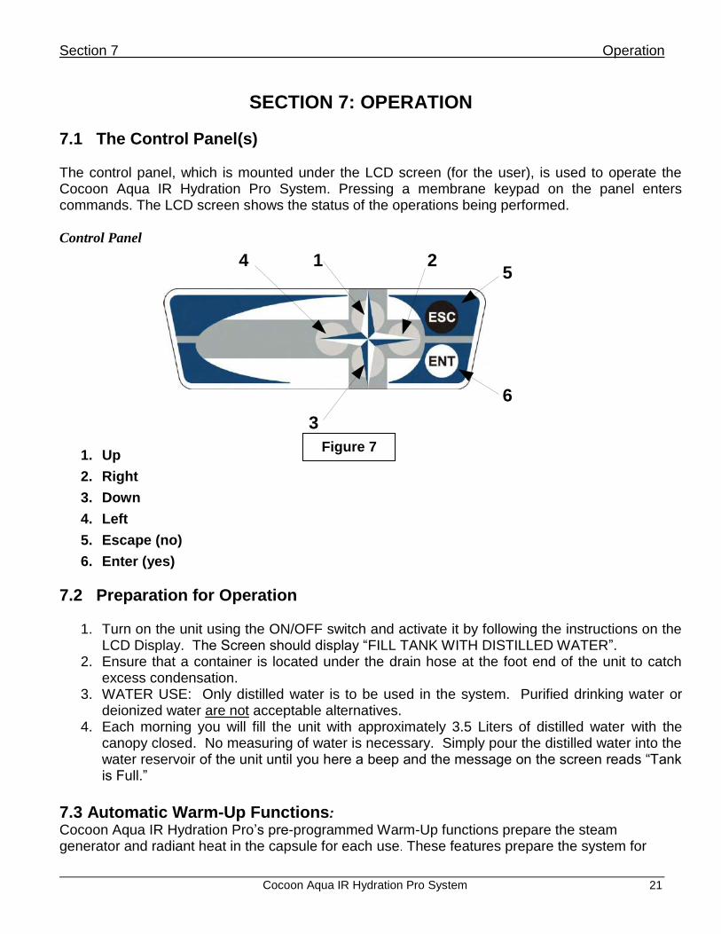
7.1 The Control Panel(s) The control panel, which is mounted under the LCD screen (for the user), is used to operate the Cocoon Aqua IR Hydration Pro System. Pressing a membrane keypad on the panel enters commands. The LCD screen shows the status of the operations being performed. Control Panel
1. Up
2. Right
3. Down
4. Left
5. Escape (no)
6. Enter (yes)
7.2 Preparation for Operation
1. Turn on the unit using the ON/OFF switch and activate it by following the instructions on the
LCD Display. The Screen should display “FILL TANK WITH DISTILLED WATER”. 2. Ensure that a container is located under the drain hose at the foot end of the unit to catch
excess condensation. 3. WATER USE: Only distilled water is to be used in the system. Purified drinking water or
deionized water are not acceptable alternatives. 4. Each morning you will fill the unit with approximately 3.5 Liters of distilled water with the
canopy closed. No measuring of water is necessary. Simply pour the distilled water into the water reservoir of the unit until you here a beep and the message on the screen reads “Tank is Full.”
7.3 Automatic Warm-Up Functions:
Cocoon Aqua IR Hydration Pro’s pre-programmed Warm-Up functions prepare the steam generator and radiant heat in the capsule for each use. These features prepare the system for
1 2
3
45
6
Figure 7

Section 7 Operation
Cocoon Aqua IR Hydration Pro System 22
maximum efficiency of steam production during Cocoon Aqua IR Hydration Pro programs, ensuring the unit is warmed inside efficiently for maximum client comfort whether it is for the first client of the day, running sessions back to back or the unit is idle ( not in use) during the day. The Automatic Warm-Up programs will never interrupt the use of a standard program (Prepare, Prolong, Protect, Customized). If for any reason the Automatic Warm-Up program is running when a client is preparing to use, the user simply opens the hood or presses ESC to interrupt the warm-up session and can immediately proceed with their treatment. Please see Table 1 below for each preprogrammed warm-up functions compositions, preconditions and system responses. Warm Up Functions
System Preconditions and Responses
INITIAL WARM UP AUTOMATIC WARM UP MANUAL WARM UP
Preconditions to start Hood must be closed and steam generator must be filled with water
Hood must be closed and steam generator must be filled with water
Hood must be closed and steam generator must be filled with water
Start time Starts at 3 minutes after machine is turned ON.
Starts every time the unit is filled with new water and 60 minutes after last session has ended.
Starts manually when selected from the MAIN MENU.
Special start time If the steam generator is empty and the steam generator is filled in less time then 3 minutes then the WARM UP starts immediately.
If unit is idle Automatic Warm up starts every 60 min to keep steam generator warm.
none
Duration of the program 10 minutes Total Time ( 5 min steam generator heating & 10 min infrared elements)
5 minutes Total Time ( 3 min steam generator heating & 5 min infrared elements)
5 minutes Total Time ( 5 min steam generator heating & 5 min infrared elements)
T-Max dependency Not dependent Not dependent Can not be started if T-Max block message is shown. Must start TMAX to have access to control panel
Program termination by user intervention by lifting the hood
WARM UP is terminated and WELCOME SCREEN is displayed
WARM UP is terminated and WELCOME SCREEN is displayed
WARM UP is terminated and WELCOME SCREEN is displayed
Program termination by user intervention by pressing ESC on the key pad
Questions to User: "DO YOU WANT TO STOP?" IF YES PRESS ENT. IF NO PRESS ESC.
Questions to User: "DO YOU WANT TO STOP?" IF YES PRESS ENT. IF NO PRESS ESC.
Questions to User: "DO YOU WANT TO STOP?" IF YES PRESS ENT. IF NO PRESS ESC.
Program termination by user intervention by pressing ENT on the key pad
WARM UP is terminated and WELCOME SCREEN is displayed
WARM UP is terminated and WELCOME SCREEN is displayed
WARM UP is terminated and WELCOME SCREEN is displayed
TABLE 1

Section 7 Operation
Cocoon Aqua IR Hydration Pro System 23
7.4 Initial or Automatic “Warm-Up” Session
Select the Warm-Up program with the motion buttons (UP, DOWN, LEFT, RIGHT) until Warm-Up is highlighted. Confirm your selection by pressing ENTER (see Figure 7).
The Cocoon Aqua IR Hydration Pro System automatically warms up the unit within 5 minutes. The timer will count down until the Warm-Up session is finished. Once the Warm-Up session is finished, the Welcome Screen will be displayed on the LCD screen followed by a beep.
From the Welcome Screen press ENT to go to the main menu.
To cancel the Warm-Up program at any time press the ESCAPE button (see Figure 7) and follow the instructions from the LCD screen or lift the hood.
7.5 Working with the Options Set the “Settings”:
Move with the motion buttons until the Settings box is highlighted and confirm your selection with the ENTER button (see Figure 8).
From the Settings submenu, verify that all settings are correct and make any necessary corrections. The submenu will allow you to verify/change the following setting parameters:
Version of program V XXXX*
Version of program V XXXX*
Machine type Cocoon Aqua IR Hydration Pro
Temperature Celsius (Celsius/Fahrenheit)
Control Local (Local / Ethernet)
Brightness
Audio *XXXX represents the version of your machine.
To move up/down in the submenu, use the UP or DOWN buttons (see Figure 7). To select different settings use the LEFT or RIGHT buttons.
Verify that all settings are correct and set your selections with the ENTER button. The Cocoon Aqua IR Hydration Pro System will automatically save all of your settings into the memory.
“Service” Submenu:
Move with the motion buttons until the Service box is highlighted and confirm your selection with the ENTER button (see Figure 7).
From the Settings submenu, verify that all settings are correct and make any necessary corrections. The submenu will allow you to verify/change the following setting parameters:
Vibratory bed OFF (ON / OFF)
Drainage OFF (ON / OFF)
Open liquid concentrate OFF (ON / OFF)
Total time 000,00

Section 7 Operation
Cocoon Aqua IR Hydration Pro System 24
To move up/down in the submenu, use the UP or DOWN buttons (see Figure 7). To select different settings, use the LEFT or RIGHT buttons. To go back to the previous menu, press the ESCAPE button.
VIBRATORY BED – The vibratory bed can be activated without any preset programs.
DRAINAGE – To maintain your Cocoon Aqua IR Hydration Pro System and ensure maximum productivity from the steam generator and heating element, it is necessary to flush the steam generator system at least 2-3 times a week and drain to empty every evening.
OPEN AROMA TANK- will empty all contents in liquid concentrate tank. To ensure maximum productivity, open once per day (at salon close) before draining system.
TOTAL TIME- Keeps track of how many hours the Cocoon Aqua IR Hydration Pro System has been used (tracks in hours and minutes).
Installing New Software: Software updates will ensure that you have the most up-to-date equipment in terms of programming and technology available. Follow these instructions upon receiving software upgrades.
Move UP or DOWN buttons until the INSTALL box is highlighted and confirm your selection with the ENTER button.
To install new software, please follow the Software Installation Manual instructions.
To cancel the installation process, press the ESCAPE button. NOTE: Our software update products, installation kits, and hardware requirements will be available through your dealer or distributor. Please contact your representative for pricing and details.
7.6 Operations: Selecting a Program
In Pre menu, move with the motion buttons until Programs (blue box) is highlighted and confirm your selection by pressing ENTER.
Cocoon Aqua IR Hydration Pro has 3 preset programs, 1 custom program and client tutorial for staff use only.
See Appendix D for information on the programs.
To move up/down in the submenu use the UP or DOWN buttons. Press ESCAPE to go back to the previous menu.
Press ENTER to start the selected Cocoon Aqua IR Hydration Pro program.
7.7 Adjusting Features with a Selected Pre-Program You can change and adjust all available (visible) functions with the touch of a button on the control panel. Programs 1 - 3 are preset programs and have selected default settings for easy use. Program 4 (customized) has no default settings and no preprogrammed activities—all functions are to be selected by the user or the technician. Program 5 is the client tutorial intended for staff use only to train a first time Cocoon Aqua IR Hydration Pro user.

Section 7 Operation
Cocoon Aqua IR Hydration Pro System 25
a. AUDIO (speaker ON/OFF) b. BRIGHTNESS (of LCD display) c. FACE AIR (10 levels) d. COLOR LIGHTS (red, blue, green, turquoise, violet, yellow)
Manual control e. VIBRATION INTENSITY f. STEAM (ON/OFF) (available in Custom programs only) g. TEMPERATURE (between 25oC [77oF] and 48oC [118oF])
a. Audio Activate the Audio function on the LCD display by pressing the motion buttons (UP,
DOWN, LEFT, RIGHT) and make your selection by pressing the ENTER button (see Figure 7).
From the Audio submenu, make your choices and confirm your selection by pressing ENTER.
NOTE: Your selections must be confirmed by pressing ENTER. If you press ESCAPE only, the default settings will be restored.
b. Temperature: To select the desirable steam sauna temperature, activate the Temperature field and
press ENTER. Press the LEFT button to reduce the set temperature and press the RIGHT button to increase the set temperature.
Press ESCAPE to get back to the Program Menu. CAUTION: When using Radiant Heat, be sure to refrain from touching the upper portion of the inside of the cabinet. The radiant heat emitters are located in this area and become very hot when the Radiant Heat feature is in use. Make sure that the chest is always a minimum of four inches from the radiant heat emitters.
c. Vibratory Bed:
To turn on vibration, simply activate the vibration function field and press ENTER.
To control intensity in this mode, choose the SPEED control from the Vibratory Bed submenu and simply press the LEFT or RIGHT buttons until your desired level is reached. Confirm your selections by pressing ENTER.
To turn OFF vibration in either mode, choose OFF from the Vibratory Bed submenu. Confirm your selection by pressing ENTER.
d. Face Air: To turn on the fan, highlight the Face Air function field and press ENTER.
To control intensity in this mode, press LEFT or RIGHT buttons in the Face Air submenu until your desired level is reached. Confirm your selections by pressing ENTER.
NOTE: Your selections must be confirmed by pressing ENTER. If you press ESCAPE only, the default settings will be restored.

Section 7 Operation
Cocoon Aqua IR Hydration Pro System 26
FACE AIR
e. Color Lights:
To choose different colors from the preprogrammed Color Light section, activate the Color Lights field and press ENTER. Scroll to highlight “Pick a Color” and press ENTER.
By choosing the Manual control you can select the desired color and confirm the selection by pressing ENTER. Once you have selected your favorite color that color will remain on throughout the rest of your session unless you make additional color changes/selections.
f. Aroma/Liquid Concentrates: The aroma feature included with your Cocoon Aqua IR Hydration Pro is conveniently located by the steam outlet at the foot of the bed.
To use the aroma liquid diffusion system: 1. Pour 1 oz. of the selected Oxygen Science™ concentrate into the aroma intake
reservoir at the foot of the machine. The concentrate will automatically disperse during session.
NOTE: Regarding Aroma Oils! 1) Essential oils must NOT be used in the aroma reservoir.
2) Use of pure essential oils within the aroma diffuser tank WILL CAUSE DAMAGE to the plastic tank and flow valve.
3) Use only Oxygen Science concentrates in the aroma reservoir of the system! Use of any other non-approved concentrate in your unit will immediately void your product warranty.

Section 7 Operation
Cocoon Aqua IR Hydration Pro System 27
7.8 Safety Shut Off: Lifting the Hood During a Session If you open the Cocoon Aqua IR Hydration Pro System’s hood during the session, the Steam and Radiant Heat will switch off automatically. After shutting the hood once again the unit will begin warming up and steaming, but it can take a few minutes for the temperature to climb in the system and steam to be produced.
7.9 Stopping Your Session You can stop your session at any time by pressing the ESC button. The notation on the LCD panel will read “Do you want to stop?” Press ENTER and you will exit the program. If you do select ENT and stop a program before the session time is complete, the unit will automatically drain any excess water not used during the session. This will ensure that the notation appears on the LCD screen to “FILL TANK WITH DISTILLED WATER” so that your staff will fill the appropriate amount of water needed for the next session and no session ever runs out of water. You can also stop your session by simply lifting the hood.
7.10 Turning Off Your Cocoon Aqua IR Hydration Pro System It is not necessary to turn off your Cocoon Aqua IR Hydration Pro System in between sessions. Simply turn the unit off via the on/off button located at the head of the unit each evening before closing your establishment. Power the unit on each morning.

Section 8 Service (Hood)
Cocoon Aqua IR Hydration Pro System 28
SECTION 8: SERVICE (HOOD)
8.1 Removing the Hood Cover
Required tools: crosshead screwdriver
Remove 2 screws and pull the cover in the direction of the arrow.
8.2 Removing the Hood and Changing the Strut Nut
Required tools: wrench 10mm, 13mm, and two people
Removal: a. Remove panels and hood cover. b. Disconnect electrical wires. c. Open capsule and unscrew strut nuts. d. If you are changing the struts, install new instead of old. e. For hood removal, close capsule and remove hinge pins using punch and
hammer.
Installation: a. Install hinge pins. b. Open capsule and connect struts.
c. Close hood and connect water and electrical wires.
Name Part Number
Strut E4000-28
Hinge

Section 8 Service (Hood)
Cocoon Aqua IR Hydration Pro System 29
8.3 Heat Emitter
Required tools: crosshead screwdriver
Removal: a. Disconnect wires. b. Remove screws and remove parts as shown in the figures in below.
Installation: a. Install parts as shown in the figure below. b. Connect wires.
NOTE: When replacing screws, use stainless steel screws.

Section 8 Service (Hood)
Cocoon Aqua IR Hydration Pro System 30
8.4 Speaker
Required tools: crosshead screwdriver
For speaker removal, remove four (4) screws and retain nut clips.
For speaker installation tighten screws into nut clips.
Name Part Number
Speaker E4000-31
Name Part Number
Heat emitter E4000-19
Screw fixing ring E4000-25
Reflector gasket E4000-21
Glass E4000-22
Glass gasket E4000-23
Screw spacer ring
Connecting screw E4000-30

Section 8 Service (Hood)
Cocoon Aqua IR Hydration Pro System 31
8.5 Temperature Sensor
Required tools: large pliers
The temperature sensor is inserted through the hood and secured with a nut. The nut is round and pliers are required for its removal.
The sensor is connected to “LCDRA2 in LCD housing”. See “Opening the LCD Housing” and “Replacing Parts in the LCD Housing” on the following pages for information on disconnecting wiring.
8.6 Opening the LCD Housing Principal scheme of devices in hood
Required tools: crosshead screwdriver
Move LCD housing position as shown in the figure below.
Remove seven (7) screws.
Keep two (2) housing parts together and turn it to the horizontal position, then lift the upper part.
Name Part Number
Temperature sensor E4000-32

Section 8 Service (Hood)
Cocoon Aqua IR Hydration Pro System 32
8.7 Replacing Parts in the LCD Housing

Section 8 Service (Hood)
Cocoon Aqua IR Hydration Pro System 33
Face Fan
Required tools: crosshead screwdriver
Remove the connector “FAN” from the “LCDrx” PCB.
Remove four (4) screws that hold the fan in position. LCD Panel
Required tools: crosshead screwdriver, knife, silicon glue
Removal: a. Remove all connectors from the “LCDrx” PCB. b. Remove two screws from the “LCDrx” PCB and take off “LCDrx” PCB. c. Cut glue in edges of LCD panel. d. Remove two screws from LCD mounting bracket and carefully remove LCD
display from housing.
Installation: a. Put LCD panel into position and put some glue drops at the bottom corners. b. Install the two (2) screws into the LCD mounting bracket. c. Put “LCDrx” PCB into position and install two (2) screws. d. Install all connections.
NOTE: There is no difference between control panel 1 and control panel 2 (connections KBD1 and KBD2). Upper Control Panel
Required tools: crosshead screwdriver
Removal:
a. Remove “LCDrx” PCB. b. Remove 2 screws from the control panel.
Installation: a. Install two (2) screws in the control panel. b. Install the “LCDrx” PCB and fasten all connectors.

Section 8 Service (Hood)
Cocoon Aqua IR Hydration Pro System 34
Lower Control Panel Removing and installing the lower control panel is the same as the upper control panel with one difference–the control panel plug is larger than the holes. Replacement control panels are sent with the connector not installed.
Install the control panel and route the connection cable to “LCDrx” PCB.
Insert wires into the supplied plug according to the next diagram.
Name Part Number
LCD housing upper part E4000-33
LCD housing lower part E4000-34
Polyurethane arch E4000-35
LCD display E4000-02
PCB LCDrx E4000-03
PCB rabbit E4000-04
Electronic box for main PCB E4000-06
Face fan E4000-17
Control Panel E4000-01

Section 9 Service (Bottom)
Cocoon Aqua IR Hydration Pro System
35
SECTION 9: SERVICE (BOTTOM)
9.1 Removing Side Panels BEFORE ANY REPAIR AND/OR INSPECTION OF THE UNIT, THE ELECTRICAL SUPPLY MUST BE SHUT OFF. BEFORE REMOVING THE SIDE PANEL OF THE UNIT, SHUT OFF THE ELECTRICAL SUPPLY TO THE UNIT.
Tools/Supplies required: Phillips Head screwdriver, flat head screwdriver, 2 people
Removal (remove the right side panel first): a. Use a small flat head screwdriver to gently remove the white
plastic caps over the 10 screws. There are 3 on each end and 2 on each side.
b. Use the Phillips Head screwdriver to remove the 10 screws. c. While another person slightly lifts the front of the machine,
carefully remove the right side panel by gently pulling down and outward on the right panel.
d) Remove the left panel in the same manner.
9.2 Drainage Drainage is connected to bottom floor. Smell lock has 40 mm tube. All tubes are usually 40 mm. For cleaning, remove cover and take away smell lock.
Name Part Number
Smell lock E4000-36

Section 9 Service (Bottom)
Cocoon Aqua IR Hydration Pro System
36
9.3 On-off Switch
The on-off switch breaks electric input when you press it. A temperature increase could cause the unit to automatically shut off. To resolve this problem, remove the right side skirt and disconnect the air tube from the tube connection nipple on the switch.
Name Part Number
Power switch (in electric box) E4000-39
Air tube E4000-38
Air switch E4000-37
9.4 Aroma System 1 Required tools: large pliers 2 The aroma system is shown in the following figures. 3 Valve is connected with tube to steam system.
Aroma system electrical diagram:
Name Part Number
Aroma tank – upper E4000-109
Aroma tank – lower E4000-108
Level sensor E4000-93

Section 9 Service (Bottom)
Cocoon Aqua IR Hydration Pro System
37
9.5 Vibratory Bed 1 Required tools: crosshead screwdriver, knife, wire cutters, wire strippers, wire
crimper, silicone
The vibration system has three (3) electrical motors with EMC filters. The motors with filters are connected to special nests on the back of the beds. Two (2) motors and filters are located on the upper bed, and one (1) motor and filter is located on the lower bed. Two (2) electrical connections for the beds are located on the capsule bottom floor. To remove motors and filters from bed for replacement, follow steps below: 1 Remove the 4 crosshead screws from the cover on the nest. 2 Use a knife to cut around the seam between the cover and the nest to remove the
silicone. 3 Remove the cover from the nest. 4 Use wire cutters to cut all wires from the splices. 5 Remove two (2) screws from the filter bracket and remove bracket to remove the
filter.
Section 9 Service (Bottom)
Cocoon Aqua IR Hydration Pro System
38
6 Remove four (4) screws from the motor brackets. Remove the brackets to remove the motor.
7 If replacing bed, remove cable from the nest to use in new bed. 8 Install motor and filter in reverse order. 9 When installing cover, make sure to apply silicone around the edge of the cover to
ensure watertight seal to the nest.
Name Part Number
Motor+EMC filter E4000-08
Vibration bed upper E4000-89 (w/o motor)
Vibration bed lower E4000-91 (w/o motor)
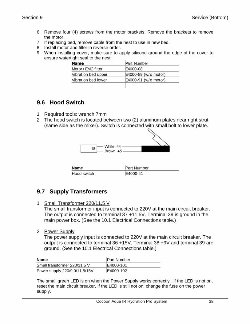
9.6 Hood Switch 1 Required tools: wrench 7mm 2 The hood switch is located between two (2) aluminum plates near right strut
(same side as the mixer). Switch is connected with small bolt to lower plate.
Name Part Number
Hood switch E4000-41
9.7 Supply Transformers
1 Small Transformer 220/11,5 V The small transformer input is connected to 220V at the main circuit breaker. The output is connected to terminal 37 +11.5V. Terminal 39 is ground in the main power box. (See the 10.1 Electrical Connections table.)
2 Power Supply The power supply input is connected to 220V at the main circuit breaker. The output is connected to terminal 36 +15V. Terminal 38 +9V and terminal 39 are ground. (See the 10.1 Electrical Connections table.)
Name Part Number
Small transformer 220/11.5 V E4000-101
Power supply 220/9.0/11.5/15V E4000-102
The small green LED is on when the Power Supply works correctly. If the LED is not on, reset the main circuit breaker. If the LED is still not on, change the fuse on the power supply.

Section 9 Service (Bottom)
Cocoon Aqua IR Hydration Pro System
39
9.8 Steam Generator NOTE: When you are working with the steam generator always disconnect capsule from power supply! 1 The generator is connected to the wooden platform with 4 screws. Wires are
not displayed in the figure. Nuts are in metric system.
Electrical Diagram of Steam Generator NOTE: When you are working with the steam generator always disconnect capsule from power supply!
9.9 Replacing the Heating Element
3 Required tools: flat screwdriver, 10mm wrench 4
5) Removal: a. Remove protective cover nuts. b. Loosen cable grip nuts and pull cover away along cables. c. Disconnect wires in cable #3 from heating element. d. Loosen heating element turning nut three (3) turns to reduce the
pressure on the rubber retainer, but do not remove the nut completely.
e. Pull heating element out.
Installation: a. Loosen securing nut and push the heating element securely into
the steam generator. Tighten the securing nut approximately three
Section 9 Service (Bottom)
Cocoon Aqua IR Hydration Pro System
40
(3) turns. b. Install wires from cable #3 onto the heating element. c. Close protective cover. d. Install the two (2) nuts and tighten the cable grip nuts.
9.10 Replacing the Thermal Fuse 1
2) Required tools: small flat screwdriver, 10mm wrench 2 Removal:
a. Remove the two (2) protective cover nuts. b. Loosen the two (2) cable grip nuts and pull cover away along
cables. c. Remove cable #4 wires from the white terminal strip. d. Remove nut securing white terminal strip to the steam generator. e. Remove thermal fuse.
Installation: a. Push thermal fuse all the way into position. b. Secure white terminal strip to steam generator. c. Connect cable #4 wires to the white terminal strip.
d. Install protective cover nuts and tighten cable grip nuts.
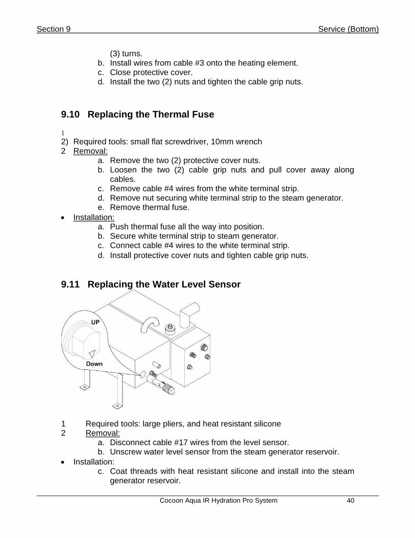
9.11 Replacing the Water Level Sensor
1 Required tools: large pliers, and heat resistant silicone 2 Removal:
a. Disconnect cable #17 wires from the level sensor. b. Unscrew water level sensor from the steam generator reservoir.
Installation: c. Coat threads with heat resistant silicone and install into the steam
generator reservoir.

Section 9 Service (Bottom)
Cocoon Aqua IR Hydration Pro System
41
d. Connect cable #17 wires to the level sensor. NOTE: Be sure that small triangle is directed down. NOTE: If you change water level sensor, check that the thermal fuse and heating element are in proper working order. Name Part Number
Water level sensor 302240-08
Thermal Fuse 302240-07
Heating Element 302240-38

Section 10 Advanced Electronics and Troubleshooting
Cocoon Aqua IR Hydration Pro 42
SECTION 10: ADVANCED ELECTRONICS AND TROUBLESHOOTING
10.1 Electrical Connections All ports in PCB are numbered. Their cable number and description are in the following table.
NOTE: Manufacturer reserves the right to change technical aspects on the products without prior notice.
Port No Color of w ire Cable description Cable No Port No Color of w ire Cable description Cable No
1 Blue 36 Brow n +15 V
2 Brow n 37 Red + 11,5 V
3 Blue 38 Blue + 9 V
4+ Brow n 39 Black -GND
GND Green+yellow 40 Empty
3 Blue 41 Empty
4+ Brow n 42 White 17
GND Green+yellow 43 Brow n
5 Brow n 44 White 18
6 Empty 45 Brow n
7+ White 46 White 19
8 47 Brow n
9 48 Green
10 49 Empty
11 50 Empty
12+ 51 Black 20
13 Brow n 52+ Red
14 53 - Audio line IN
15+ White 54 - Headphones
16 55 Blue 4
17 56 Brow n
18 U0 Blue 2
19 U1 Brow n
20 GND Green+yellow
21 U2 Blue 3
22+ U3 Brow n
23 GND Green+yellow
24 N Blue 1
25 L Brow n
26 GND Green+yellow
27
28
29+
35+ -
35+ -
35+ -
35+ -
Aroma level sensor
Gen. w ater level
Hood Sw itch
4 Chromotherapy
lamps.
No difference
betw een ports.
Speaker
Generator thermal
melting fuse
3 parallel connected
IR emitters
Steam
Mains
Empty
Empty
Drain 10
Aroma 8
Empty
Vibro bed 7
Transformer
230/11,5 V5
from
pow er supply
Vibro bed 6
4 color light lamps
Transformer 220/11,5 V
3 parallel connected Heat emitters
Section 10 Advanced Electronics and Troubleshooting
Cocoon Aqua IR Hydration Pro 43
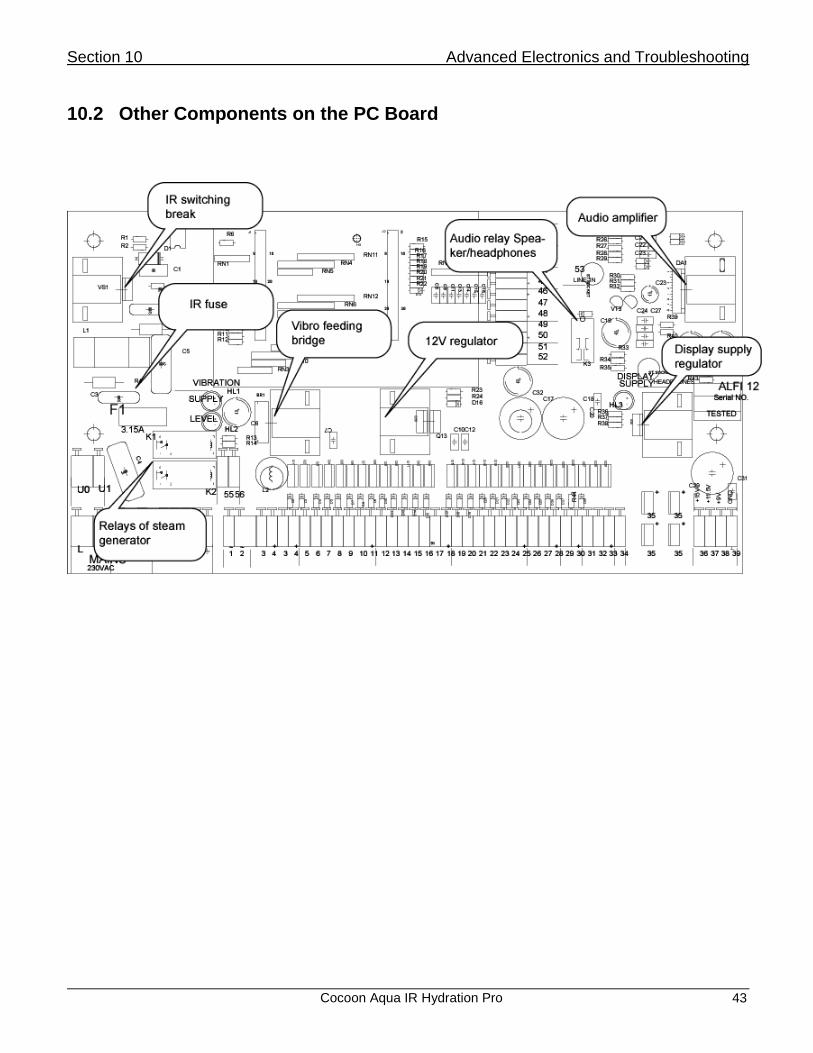
10.2 Other Components on the PC Board

Section 10 Advanced Electronics and Troubleshooting
Cocoon Aqua IR Hydration Pro 44
10.3 Troubleshooting
Always try to restart the capsule before any troubleshooting.
LCD Display Error Messages
Message Trigger Probable Cause Corrective Action
System damage!
Data communication between upper PC board (LCDrx) and lower PC board (Rabbit) is loose
Plug is loose Check the plug connections between upper and lower PC boards
Capsule is blocked Press ON/OFF switch. If you don’t hear the characteristic noise inside the right panel see “On-off Switch”
HOOD OPEN! Hood opening Plug is loose
Check the plug between magnetic switch and PC board
Faulty magnetic switch See “Hood Switch”
READY Warm-up program is finished properly
- Press ENTER to selections
NOT READY Warm-up program is currently running (7min)
Warm-up program did not finish Press ESCAPE to get back to MAIN MENU
Restart the Cocoon Aqua IR Hydration Pro using ON/OFF switch
NO INCOMING WATER!!!
Cocoon Aqua IR Hydration Pro steam generator did not get the water during 15 sec from injection valve opening
Wall faucet is closed Open wall faucet
Generator filling valve faulty Check valve 29 connections and power
Water pressure loss Check the water filter for proper operation
WATER TANK EMPTY!!!
Cocoon Aqua IR Hydration Pro steam generator did not get the water during 25s from injection valve opening
Wall faucet is closed Open wall faucet
Generator filling valve faulty Check valve 29 connections and power
Water pressure loss Check the water filter for proper operation
HEATER COMBUSTION!!! (Heater fault)
The steam generator thermal fuse is blown
Thermal fuse is blown See “Replacing the Thermal Fuse”. Check the heating element too - it may be damaged as well
ADD UP TO 300ml AROMA LIQUID!
Aroma tank is empty
Aroma tank is empty Add aroma liquid
Level sensor adjustment of sensitivity
Adjust the sensitivity level sensor See “Aroma System”
Level sensor plug is loose See “Aroma System”
Level sensor wrong position See “Aroma System”
Level sensor faulty See “Aroma System”
FILL THE WATER TANK!
Cocoon Aqua IR Hydration Pro steam generator does not have enough distilled water to start the steam session
Don’t have enough water Add distilled water
Upper level sensor plug is loose
Check the connection between sensor and PC board
Upper level sensor faulty See “Replacing the Water Level Sensor”

Section 10 Advanced Electronics and Troubleshooting
Cocoon Aqua IR Hydration Pro 45
Message Trigger Probable Cause Corrective Action
WATER TANK FULL! Cocoon Aqua IR Hydration Pro steam generator is full
Water tank is full Do not add water Start the steam session
Water level sensor(s) plug is loose
Check the connection between Sensor and PC board
STEAM ACTIVATING ON MENU IS OK BUT NO STEAM
Thermal fuse is blown
Check the heating element too - it may be damaged as well. See “Replacing the Thermal Fuse” and “Replacing the Water Level Sensor”
Hood is open Close hood
Water level sensor(s) plug is loose
Check the connection between Sensor and PC board
Water level sensor(s) faulty See “Replacing the Thermal Fuse” and “Replacing the Water Level Sensor”
Heating element is burned See “Replacing the Heating Element”
VIBRATORY BED DOESN’T FUNCTION
Plug is loose Check plug connection under the vibratory bed
Motor short circuit See “Vibratory Bed”

Section 11 System Cleaning, Maintenance and Reinstallation
Cocoon Aqua IR Hydration Pro System 46
SECTION 11: SYSTEM CLEANING, MAINTENANCE AND
REINSTALLATION
11.1 General Cleaning and Mandatory Use of Pre-Approved Solution Pre-trained personnel must do all cleaning via written instructions. All plastics and poly carbonate surfaces including the inside and outside of system hood, underbed area and poly carbonate shell, as well as accessories in your Cocoon Aqua IR Hydration Pro System must be cleaned and disinfected using a pre-tested, pre-approved cleaning solution called Accel TB .05% solution. Accel offers a new technology within this disinfectant, based on an active ingredient known as “Accelerated Hydrogen Peroxide (AHP)” or ”Stabilized Hydrogen Peroxide (SHP)” for hard-surface antimicrobial applications. AHP is a cleaner and disinfectant designed for high risk areas such as health care facilities but is safe, effective and environmentally friendly. Facts about ACCEL TB:
a. Effective cleaner b. Effective disinfectant c. Highly efficient (only requires soaking on the material for 60 seconds as
opposed to traditional cleansers whose warnings require up to 10 minutes for total disinfecting)
d. Non-toxic e. Non-corrosive ( this relates to the skin, eye, as well as surfaces) f. Biodegradable
Certifications for the Product: Active Ingredient: Accelerated Hydrogen Peroxide MSDS Specification: See below EPA: 74559-1 OSHA: The product meets the U.S. Occupational Heath and Safety Administration (OSHA) blood-borne pathogen standards for cleaning blood and bodily fluids.
Average Product Usage: Each 32oz. bottle should provide a minimum of 30 full unit cleanings. Product Ordering Procedure: The product is available in 32oz. bottle size and is sold in a case of 12 bottles. You will place all reorders with any Cocoon Aqua IR Hydration Pro Consultant . Just call 1-877-818-9988 and ask for your Cocoon Aqua IR Hydration Pro Territory Manager to place your order. Cleaning instructions using Accel Solution are as follows: There is no product dilution with this solution.

Section 11 System Cleaning, Maintenance and Reinstallation
Cocoon Aqua IR Hydration Pro System 47
1. Spray desired area/surface with Accel TB .05% disinfecting solution. 2. Let solution sit for 60 seconds. 3. Wipe surface dry and clean with a soft cloth or paper towel.
Note: Rinsing is not allowed on the exterior hood or on the side panels of the Cocoon Aqua IR Hydration Pro. Note: Abrasive detergents and scrubbing must not be used to clean the unit. This may result in serious damage to the plastic surfaces of the unit. In addition to abrasive detergents, it is strictly forbidden to use cleaning agents containing acetone, ammonia, petrol, benzene, window/glass cleaners or varnish removers.
Use ONLY the approved Accel TB Cleaning Solution. Use of any and all other cleaning products for cleaning and disinfecting your unit will immediately void your product warranty covering the Polycarbonate material on the machine.
11.2 Cleaning the Shell Your Cocoon Aqua IR Hydration Pro System is shipped to you wrapped carefully in clear plastic wrap. The plastic wrap will keep your Cocoon Aqua IR Hydration Pro System clean and safe during its journey, but the plastic causes one minor side effect—it leaves a slight film on the shell. We recommend that you wipe down your machine as soon as you uncrate it. To clean the inside and outside of the shell:
1. Spray on Accel TB .05% disinfecting solution. 2. Let solution sit for 60 seconds. 3. Wipe surface dry and clean with a soft cloth or paper towel. Note: Do not use any type of abrasive pad or scouring powder as they may scratch the surface finish.
11.3 Cleaning the Underbed Area The following should be done after every Cocoon Aqua IR Hydration Pro session:
1. Carefully remove bed sections from unit, unplug vibratory bed motor chords from the unit if necessary.
2. Clean dirt, dust and perspiration from underbed surfaces following directions below. 3. Spray desired surface/area with Accel .05% TB Disinfectant. 4. Let solution sit for 60 seconds. 5. Wipe surface dry and clean with a soft cloth or paper towel.

Section 11 System Cleaning, Maintenance and Reinstallation
Cocoon Aqua IR Hydration Pro System 48
11.4 Cleaning Contact Surfaces (Bed, Head Pillow, Interior of Shell)
1. Use Accel TB .05% Disinfectant on all contact surfaces AFTER EACH USE to present a clean, sanitary appearance and feel for each new client.
2. Let solution sit for 60 seconds. 3. Wipe dry and clean with paper or soft cloth towel.
NOTE: Cleaning after each use removes oils, perspiration, and cosmetics. It will also prolong the material life of the accessories and bed.
11.5 Cleaning the Steam Generator 11.5.1: Steam Drainage Process Recommended to be completed daily:
1. Turn the system On. 2. Press Enter to continue. 3. Use arrow keys to move to and highlight Service feature and press Enter. 4. Scroll down with arrow keys until Drainage feature is highlighted. 5. Press right arrow key to open drainage. You may hear a small click and water will begin
to flow from the nipple below the bed. Wait until water stops dripping. 6. Proceed by pressing left arrow key to adjust Drainage feature to “off.” 7. Press Esc. key to exit back to the main menu. Discard the excess water from drip pan.
This completes the drainage process. Leave unit empty of water each evening. Refill water in AM before first use of the day. 11.5.2: Steam System Flushing Process Recommended to be completed 2-3 times per week:
1. Turn the System On. 2. Press Enter to Continue. 3. Use arrow keys to move to and highlight Service feature and press Enter. 4. Scroll down with arrow keys until Drainage feature is highlighted. 5. Press right arrow key to open drainage. You may hear a small click and water will begin
to flow from the nipple below the bed. Wait until water stops dripping. 6. Proceed by pressing left arrow key to adjust drainage to off. 7. Press Esc key to exit back to the main menu. This completes the first round of system
flushing. Discard the excess water from the drip pan. 8. Unscrew the distilled water cap of the water reservoir. 9. Fill tank with room temperature distilled water until system indicates it is full with visual
message on LCD screen and audio beep. 10. Screw the cap back on to the distilled water reservoir. 11. Press Enter to continue. 12. Use arrow keys to highlight the Program feature and press Enter. 13. Attach a neck drape as if you were performing a full treatment. Roll a towel and place in
the area where head and neck of client would typically lie.
Section 11 System Cleaning, Maintenance and Reinstallation
Cocoon Aqua IR Hydration Pro System 49
14. Select the Prepare program. Run the program until temperature feature shows the unit is at 110 degrees Fahrenheit or more. Immediately stop the program at this point by pressing Esc then Enter.
15. Proceed to immediately drain the unit a second time by going through steps 1- 7 detailed above. You are now completing phase 2 of the draining process and hot water will be collecting in the drip pan underneath the system.
16. When system is completely empty close drainage feature, press Esc. button and then press Enter (Ent.) button.
17. Unscrew the distilled water cap. 18. Fill tank once more with room temperature distilled water until the system indicates it is
full with visual message on LCD screen and audio beep. 19. Press Enter to continue. 20. Proceed to immediately drain the unit a third time by going through steps 1- 7 listed
above. 21. When system is completely empty close drainage feature, press Esc and then press
Enter (Ent.). Note: The above process may need to be repeated twice to ensure adequate draining. Note: No cleaning disinfectants or chemical compositions of any kind should be added into the water intake reservoir of the machine for any cleaning or maintenance process. Distilled Water only must be used for the Flushing procedure.
11.6 Cleaning the Aroma/Liquid Concentrate Diffusion System 11.6.1: Aroma System Flushing Recommended to be completed nightly:
1. Turn the system on by pressing the On/Off button located at right side of head of system. 2. Press Enter on the LCD panel to continue. 3. Enter the service menu by using the directional arrows until Service feature is
highlighted. 4. Scroll down to Aroma Cup feature until highlighted. 5. Press the right arrow key to open the Aroma Cup feature. You may hear a faint clicking
sound as drainage opens. 6. All excess aroma liquid from the tank will drain from the nipple at the foot end of the unit.
Ensure that the excess aroma liquid is flowing from the nipple into drain pan before continuing to step 7.
7. Pour 4 ounces hot water into the aroma tank reservoir to remove any extra aroma liquid. This water will immediately drain from blue nipple underneath the bed, check to ensure it is draining out appropriately into drainage pan.
Note: This process can be completed with tap water.

Section 11 System Cleaning, Maintenance and Reinstallation
Cocoon Aqua IR Hydration Pro System 50
11.6.2: Aroma System Deep Cleaning Recommended to be completed once per week:
1. Turn the system on by pressing the On/Off button located at right side of head of system. 2. Press Enter on the LCD panel to continue. 3. Enter the service menu by using the directional arrows until Service feature is
highlighted. 4. Scroll down to Aroma Cup feature until highlighted. 5. Press the right arrow to open the Aroma Cup feature. You may hear a faint clicking
sound as drainage opens. 6. Let all aroma oil drain completely from the unit. 7. Look under the left foot end leg to locate the aroma tank. 8. Grasp the red connection on the end of the wire, pull away from valve. Gently unplug the
two wires that lead to the aroma valve. 9. With one hand hold the white plastic valve seat that is attached to the gray bottle cap.
With the other hand grasp the valve and twist a quarter turn clockwise. 10. Wiggle the valve to loosen and pull down and remove. 11. Use some alcohol to clean the black rubber stopper on the valve. 12. Use alcohol to clean the valve seat. 13. Reinstall the valve by inserting the valve into the seat and turning counter clockwise. 14. Reconnect the two wires that lead to the aroma valve.
11.7 Cleaning the System Drain (located under the upper vibratory bed) Recommended to be completed nightly:
1. Carefully unplug the upper and lower vibration beds. The plugs must be unlocked counterclockwise before removing male from female connectors.
2. Remove the bed section and set off to the side of the machine. 3. Use Accel disinfectant and dry towel to wipe the drain clean. A small, soft brush (i.e. a
nail brush) may be helpful. 4. Place a catch pan under the nipple under the foot end of the unit. 5. Pour a half-gallon of hot tap water down the drain to flush it out. 6. Reinstall the upper and lower vibration beds by placing the molded bed supports onto the
bed balls. Gently replace and relock the vibration bed connectors. Note: Tap water can be used for this process & an ounce of Accel solution can be added to the water if so desired.
11.8 Annual Maintenance and Periodic Inspections
IR Emitters Check
o Do all 3 IR emitters warm up?
o Does each IR emitter have a proper and functional protective flock IR cover?

Section 11 System Cleaning, Maintenance and Reinstallation
Cocoon Aqua IR Hydration Pro System 51
Flock covering will deteriorate over time, exposing metal of the protective
cover. The protective cover can heat up, and can cause a burn if a person
presses an extremity against the protective cover. It is required to annually
inspect and replace the protective flocked covers at least annually to
maintain coverage. POINT: You should change the protective flock IR
covers at least once annually for user safety purposes, your customer
satisfaction and best business operation practices.
Usage of the unit with a missing or damaged protective flock IR covers
could cause injury and is AT YOUR OWN RISK. No use of the Pod is
recommend without intact and fully installed protective flocked IR covers.
LED Clusters Check
o Check that all LED diodes are functional and lighting as expected. These LEDs
have a expected lifetime of 10,000 hours. With high usage units, we recommend
changing these at a minimum of once every 2 years to ensure functionality.
Check Speakers and Headphone Port for Functionality
o Ensure speakers produce a clear, audible signal with no hum or distortion
o Ensure when headphones are plugged in, you get a clear signal
Check Control Panel is in Working Order
o To enter the engineering/test menu, press the “Options” then “Enter” buttons
once the unit is powered on.
o All buttons on the control panel should respond to light touch without visible
damage to the buttons or face
Visual Inspection of the Unit
o Ensure the hood and shell of the cocoon are in good order without visible tears or
damage
o Ensure the neck cover is in good repair with no jagged edges, and that you can
more your hands freely through the opening
o Ensure the hood gaskets are in good order with no tears or leaks
o Ensure the LCD on the main display is in good order, with no missing issues and a
comfortable brightness setting
o Ensure the Vibration Bed is in good order. It should be clean without tears or
damage. For hygienic and esthetic purposes, Sybaritic recommends replacing the
bed every 2 years.

Section 12 Specification Information
Cocoon Aqua IR Hydration Pro System 52
SECTION 12: SPECIFICATION INFORMATION
12.1 General Dimensions of Cocoon Aqua IR Hydration Pro System Unit: Length: 90 INCHES, 230 CENTIMETERS Height: 40 INCHES, 102 CENTIMETERS (closed) Height: 84 INCHES, 213 CENTIMETERS (open) Width: 35.5 INCHES, 90 CENTIMETERS
Total Weight: 265 POUNDS/120 KILOGRAMS Power Requirements: AC 220, 50/60 Hz Amperage: 15 A (uses 13 A) Power Consumption:
2951 watts/13.41 amps/220volts (When both heat and steam sessions are running)
551 watts/2.5 amps/220 volts (When only heat session is running)
2551 watts/11.59/220 volts (When only steam session is running) Color: White NOTE: Design and specifications subject to change without notice.

Section 12 Specification Information
Cocoon Aqua IR Hydration Pro System 53
12.2 Supplied Accessories Neck drapes (1 vinyl and 50 disposable)
Water pitcher
1 Cocoon Aqua IR Hydration Pro System Owner’s Manual
1 Accel TB, Disinfectant (32 oz.)
1 Accel TB, Sprayer NOTE: Supplied accessories are subject to change. Contact your supplier with questions.

Cocoon Aqua IR Hydration Pro System
A
Owner Record The model and serial numbers are located on the leg of the right side panel. Record these numbers in the spaces provided below. Refer to these numbers whenever you call your dealer regarding this product.
Model No.: COCOON AQUA IR HYDRATION PRO SYSTEM
Serial No.:
Micro Controller Identification No.:
DISTRIBUTED BY:
NuAge Beauty 9220 James Ave. S. Minneapolis, MN 55431 Phone: 952-888-2088 Fax: 952-888-8887
WARNING
TO PREVENT FIRE OR SHOCK HAZARD: 1. DO NOT EXPOSE UNIT TO RAIN. 2. DO NOT PLACE THE UNIT IN A SHOWERING AREA OR STEAM ROOM.
CAUTION
TO REDUCE RISK OF ELECTRICAL SHOCK, DO NOT REMOVE COVER OF THE ELECTRICAL BOX INSIDE UNIT OR THE FACE PANEL. (NO USER-SERVICEABLE PARTS ARE INSIDE). REFER SERVICING TO QUALIFIED SERVICE PERSONNEL.
CONTACT DEALER, DISTRIBUTOR OR: NuAge Beauty
9220 James Ave. S. Minneapolis, MN 55431 Phone: 952-888-2088

Cocoon Aqua IR Hydration Pro System
B
Cocoon Aqua IR Hydration Pro Owner’s
Registration Form
Please FAX or SEND this Registration Form to:
NuAge Beauty 9220 James Ave. S.
Minneapolis, MN 55431 Phone: 952-888-2088
Fax: 952-888-8887
Serial Number:
Date of Purchased:
Model Number:
Business Name:
Owner's Name:
Mailing Address:
City:
State:
Country:
Telephone:
Fax:
Purchased From:
Name:
Mailing Address:
City:
State:
Country:
Telephone:
Fax:

Cocoon Aqua IR Hydration Pro System C
Standard Warranty Cocoon Aqua IR Hydration Pro
Product Warranty Term
This One Year Product Warranty will expire 12 months from the Original Purchase Invoice Date.
General Terms and Conditions
NuAge Beauty (hereinafter “NB”) agrees to provide warranty service according to the terms and conditions set forth in this document. 1. ACTIVATION: This Product Warranty shall become effective upon the original purchase date on the
invoice. 2. SERVICES INCLUDED IN THIS AGREEMENT ARE:
a) Telephone support from NB Technical Service Team between the hours of 7:30 A.M. through 5:30 P.M. CST Monday through Friday.
b) Labor, Parts and Travel with the exception of Consumables and Accessories. c) Covered Parts: Display Assembly, Main Power Box, Aroma Nebulizer Pump, Audio
Power Supply, Display PC Board, Heater - Main Assembly and Face Fan. d) Any damage to the unit incurred as a result of abuse, misuse, will not be covered under
any warranty agreement. e) Product Warranty Owner must provide NB with reasonable opportunity (as determined by
a NB Technical Representative) for verbal troubleshooting with the Owner or Owner’s Representative prior to assignment of an on-site Technician or shipment of any parts. It is at the discretion of NB Technical Services Management to make the determination to either assign an on-site Technician or require the equipment to be returned to NB for evaluation and/or repair.
f) Parts are provided on an Exchange Basis. Defective parts must be returned to NB. Shipping costs reimbursement will be determined by NB Technical Management. NB Technical Service will provide Owner with a Return Goods Authorization Number *** Return parts not received by NuAge Beauty, Inc. within 30 Days will constitute cause for invoicing of the replacement parts to the Product Warranty Owner at list price. Product Warranty Owner agrees to pay these costs, as assessed.
3. SERVICES NOT INCLUDED BUT NOT LIMITED TO IN THE PRODUCT WARRANTY ARE:
a) Service resulting from operator misuse, abuse, unreasonable wear and tear, negligence, error due to the customer’s prior refusal to perform a recommended repair.
b) Items considered normal “Operator” functions. c) Service due to modifications made by the customer that were not approved by NB. d) Service resulting from facility caused malfunctions including environmental conditions. e) Service resulting from any acts of war, terrorism, natural disaster or other force majeure. f) This Product Warranty does not cover consumable items, including Oils, Lamps, Strut-
Hydrolift and Display Face. g) If a product is not covered by warranty, customer will sign an Authorization Repair Work
Order of the evaluated findings and estimation of required work to bring the equipment up to manufacturer specifications.
4. COVERAGE HOURS: The service hours covered under this agreement are 7:30 A.M. to 5:30 P.M.
Monday through Friday local time, excluding holidays and weekends. Any service that is performed

Cocoon Aqua IR Hydration Pro System D
outside of the normal service hours will be billable at the NB published Time and Materials Rates when the service is rendered.
5. RESPONSIBILITY: NB is not responsible for acts of war, terrorism, natural disaster or other force
majeure or failure of services supplied by third party contracted or other sources. NB agrees to respond in a timely manner, but cannot be held responsible for transportation delays. Furthermore, NB cannot be held responsible for interruption of business of either party due to any other causes beyond NB’s control or revenue lost down to downtime of equipment.
6. CUSTOMER’S RESPONSIBILITES: The Customer is responsible to:
a) Maintain the equipment in an environment suitable for the operation of the equipment as instructed in the applicable Operator’s Manual.
b) Maintain the proper electrical power requirements as recommended by NB. c) Follow all operating instructions as indicated in the applicable Operator’s Manual supplied by
NB. d) Make the equipment available for service within 1 hour after the arrival of the NB Technical
Service Representative. e) Pay all charges incurred by NB due to delays in equipment access or refusal of service after
a Technical Service Representative has been dispatched and is either in-transit or on-site. f) Maintain a safe and accessible environment for the Service Personnel to service the
equipment. g) Allow NB to implement any recommended engineering change deemed necessary by NB. h) Not make any modifications to the equipment that are not approved by NB. i) Customer agrees not to employ or engage a direct or 3
rd party service technician or
organization that is not certified to service NB Equipment. Customer further agrees that any needed NB service resulting from the unauthorized repairs performed by a direct or 3
rd party
technician or organization not certified by NB, will be billed to Customer at the current NB published Time and Materials Rates and will not be covered under this Product Warranty.
j) Use ONLY the SYB approved Accel TB Cleaning Solution. Use of any and all other cleaning products for cleaning and disinfecting your unit will immediately void your product warranty covering the Polycarbonate material on the machine.
7. USE OF SUB-CONTRACTORS: Service provided under this Product Warranty may at NB’s option,
be performed by either NB or its authorized Technical Representatives or Sub-Contractors at the direction of NB.
8. PARTS REPLACEMENT: Repair materials and parts used to perform service pursuant to this
Product Warranty will be replaced only as deemed necessary by NB. NB may use repaired, rebuilt or refurbished parts as necessary in making repairs under this Product Warranty. All parts will be furnished on an Exchange Basis, with the replaced parts becoming the property of NB.
9. FREIGHT COSTS: In-bound freight costs for warranty repairs are incurred by the Customer. All
freight costs on out-bound warranty repaired equipment is paid by NB will be shipped via UPS Ground Services only. Any upgrades to Express Overnight are the responsibility of the Customer. Under this Product Warranty Policy Customs Clearance, Duties or Taxes are not part of the freight expense cost. This warranty policy considers freight costs as transportation expense only, not administrative or government fees mandated by local governments. ***If it is determined the equipment is not covered under warranty due to misuse, the customer incurs all freight charges.
10. LIMITATION OF LIABILITY: The liability of NB hereunder is agreed to be limited to the amount
equal to the total amount of all payments made by Customer pursuant to this Product Warranty Agreement and by acceptance of the Product Warranty Agreement. Customer hereby waives any and all claims for incidental, special, consequential or punitive damages. Customer agrees to hold NB harmless and indemnified from any and all such claims by Customer and its agents, servants, employees and its successors and assigns.

Cocoon Aqua IR Hydration Pro System E
11. FORCE MAJEURE: Neither party shall be liable for any failure or delay in performance under this Agreement (other than for delay in the payment of money due and payable hereunder) to the extent said failures or delays are proximately caused by causes beyond that party's reasonable control and occurring without its fault or negligence, or party to substantially meet its performance obligations under this Agreement, provided that, as a condition to the claim of non-liability, the party experiencing the difficulty shall give the other prompt written notice, with full details following the occurrence of the cause relied upon. Dates by which performance obligations are scheduled to be met will be extended for a period of time equal to the time lost due to any delay so caused.
12. ENTIRE AGREEMENT: This agreement contains the whole agreement between the parties in
regards to extended warranties. There are no other terms, obligations, covenants, representations, statements, or conditions, oral or otherwise, of any kind whatsoever regarding this Product Warranty.
13. JURISDICTION AND GOVERNING LAW: Disputes arising under this Extended Warranty
Agreement shall be exclusively subject to the jurisdiction of the federal courts of the United States and/or the state courts of Hennepin County, State of Minnesota and jurisdiction therefore shall rest solely in Minnesota, without regard to principles of conflicts of law that would require or permit the application of the substantive law of any other jurisdiction.
14. ASSIGNMENT OF BINDING AGREEMENT: Customer shall not assign or transfer its rights under
this Product Warranty without the prior written consent of NB. The provisions of this Product Warranty are binding upon all successors, administrators, trustees and permitted assigns of Customer. This Product Warranty may be amended, altered or changed at any time by NB only.
How to Obtain Product Warranty Service
Contact NuAge Beauty Customer Service Department at: Tel: 877-818-9988 or 952-888-2088 Fax: 952-888-8887 E-mail: [email protected] Mail: NuAge Beauty, 9220 James Avenue S., Bloomington, MN. 55431 USA

COCOON AQUA IR HYDRATION PRO
PROGRAM FEATURES
Program 1: Super Hydration
Program 2: Ultra Brightening
Program 3: Cleanse
Program 4: Weight Management
Music on: 0-20 min.
Music on: 0-20 min.
Music on: 0-25 min.
Music on: 0-30 min.
Steam: 0-20 min. @ 118º
Steam: 0-20 min. @ 118º
Steam: 0-25 min. @ 118º
Steam: 0-30 min. @ 118º
Radiant heat: 0-20 min. on high
Radiant heat: 0-20 min. on high
Radiant heat: 0-25 min. on high
Radiant heat: 0-30 min. on high
Vibratory Massage: 0-20 min. continuous @ level 4
Vibratory Massage: 0-20 min. continuous @ level 7
Vibratory Massage: 0-25 min. continuous @ level 6
Vibratory Massage: 0-30 min. continuous @ level 8
Color: Fades and changes (60 second intervals)
Color: Fades and changes (60 second intervals)
Color: Fades and changes (60 second intervals)
Color: Fades and changes (60 second intervals)
Face Air: Level 3 Face Air: Level 5 Face Air: Level 6 Face Air: Level 7
Program 5: Customize
0-30 min. @ 73º - 188º F
Note: Client must turn on all features.
Program 6: Client Tutorial
This program is inactive, meaning it will not produce steam or radiant heat. It is simply a
software walk-through tutorial for clients to teach them how to navigate into a program and
through feature changes in a program. T-MAX must be set in order to get into this option, as
with the standard programs.