Embed Size (px)
Citation preview

8/3/2019 Coax Stubs
http://slidepdf.com/reader/full/coax-stubs 1/13
Some Q&A About Coax and Stubs for Your HF StationBy Jim Brown K9YC
Second Edition – October 2011
Q: What do I look for when buying coax for my HF station?A: First and foremost, look for a manufacturer you can trust. Don't buy un-branded or off-brand coax! Look for physical properties that match your use – UV resistant to stand up tosunlight, consider weight if it will feed a flat wire dipole, look for "flooded" or armored coaxif it must lay on the ground and resist varmints. The most important electrical property isloss, and loss below about 250 MHz is entirely the result of conductor resistance.
Q: What do RG numbers mean?A: Not much. For all practical purposes, RG-numbers describe only the impedance andapproximate size. RG58 is a 0.2-inch diameter 50 ohm cable suitable for very short runs.RG59 is a 75 ohm cable of about 0.25 inches diameter. RG8X is about 0.25-inch, lower lossversion of RG58, and RG6 is about 0.3-inch, lower loss version of RG59. RG8, RG213, andRG214 are about 0.4-inch diameter 50 ohm cables; 0.4-inch 75 ohm cables are calledRG11. RG174 and RG187 are miniature (0.1-inch diameter) 50 and 75 ohm cables.
RG numbers were the original specification for coax during the military buildup for WorldWar II, when not much happened above 30MHz (other than radar) and the onlycommercial use of radio was AM broadcasting. In those days, RG numbers did meansomething, and defined everything that mattered. That all changed in the 50s, with the
growth of FM and TV broadcasting, which brought about MATV (Master Antenna TV)receiving systems for buildings, and CATV (community antenna TV) receiving anddistribution systems to serve entire communities. We learned how to reduce UHF loss withfoam dielectrics, and to reduce cost and weight with lightweight foil shields andcopperweld (copper coated steel) center conductors. A 1970 Belden catalog lists 14 RG59cables; their 2006 print catalog lists 52 of them. These cables differ in many importantways – braid or foil shields that may be copper, aluminum, or both, solid or strandedcopper center, or copper coated steel center. Their outer jacket may resist UV, or not.Many are designed for use indoors, where their jackets and dielectrics must not burn orcreate noxious fumes (the real Towering Inferno was caused by burning cables). Some havebeefy copper shields for use with broadcast video or in transmitting applications, othershave thin foil/braid shields for use in those MATV and CATV systems.
Q: Do I need cable with a "low loss" foam dielectric for my HF station?A: Not necessarily. At HF, all that really matters is big copper, both in the center conductorand the shield. A foam dielectric reduces loss at UHF – it provides no benefit on the HFbands, and it costs more! However – a foam dielectric can require the use of a largercenter conductor for a given shield diameter. That larger copper reduces loss, especially onthe HF bands.
Q: Published specs for many cables don't show attenuation below 50 MHz.A: That's because most coax is used at VHF and UHF, and because loss in coax is relativelysmall at lower frequencies. For short runs on 160M and 80M, it doesn't matter. But if you're running hundreds of feet, it can matter a lot. If there's no spec for attenuation at HF,the spec to look for is the DC resistance (DCR) of the center conductor and the shield. Addthose two resistances together, and look for a value of 3 ohms/1000 ft or less for RG8, 7ohms or less for RG8X.
Q: Doesn't skin effect make DC resistance irrelevant?A: No! While skin effect concentrates current in the skin of the conductors, it is theresistance of that skin that adds IR drop that burns power and degrades shielding. The R-value that plugs into that equation is the resistance at the frequency of interest, and thatresistance starts with the DC resistance and increase with frequency! Bottom line –reducing the DC resistance of that outer skin reduces loss and improves shielding!
Q:What's the relationship between size and loss?A: The characteristic impedance of cable depends on the ratio of the diameter of theconductors and their spacing, and the loss is directly related to the resistance. That means

8/3/2019 Coax Stubs
http://slidepdf.com/reader/full/coax-stubs 2/13
we need big copper to minimize loss! Bigger coax can also handle more power, but that'snot the only reason we use it – it also provides lower loss.
Q: I'm only running 100 watts. Isn't RG8 or RG11 overkill for wire antennas?A: It depends on the length of your feedlines, the operating frequency, and how much a dB(or two) is worth to you. Study the graph below, which shows the loss for 100 ft of thebest coax on the HF bands. If your feedlines are 100 ft or less, loss will be less than 1dB on40M and below, so an RG8X like LMR240, Belden 9258, or the Wireman's CQ118 are a
good choice. On the other hand, if you're running 200 ft to a tri-bander on a tower, thatsmaller coax would burn more than half of your transmitter's power on 15M and 10M! If you're using a dipole to cover all of 80/75M, the increased SWR away from resonanceincreases loss. Note also that these data are for very good coax cables by majormanufacturers. Off-brand cables are often made with much less copper, and have greaterloss.
Manufacturers Published Data, LMR400 and 3227 are measured dataQ: What about copper coated steel and copper coated aluminum?A: For frequencies below 10 MHz, avoid copper-coated steel. At higher frequencies, skineffect takes over, and all the current is in the thin copper coating, but at lower frequencies,the steel increases the resistance (and the loss). Measurements of LMR400, which has acopper coated aluminum center conductor, show no increased loss due to the higherresistance of the aluminum, even as low as 1 MHz.
Q: What about shielding?A: The shielding provided by coax depends primarily on two factors. First, the resistance of the shield – the lower the resistance, the better the shielding. Second, the density andhomogeneity of the shield – that is, a shield that is more dense and more uniform providesbetter shielding. This is where quality of manufacture comes into play – cut into cheap coaxand you'll find relatively thin copper braid. For best shielding, look for coax that combinesa heavy copper braid with a dense layer of foil.
Q: I have a high power, multi-transmitter station. Can I use RG58 or RG8X between mytransceiver and amplifier?A: Smaller coax cables like RG58 and RG8X provide less shielding than larger coax, thanksto the higher resistance of their shields. To minimize inter-station interference, use coaxwith a beefy copper shield for all cables.
Q: How can I use 75 ohm coax for a transmitting antenna? Aren't all transmitters 50 ohms?A: While most transmitters and power amps are designed to match 50 ohm loads, most of

8/3/2019 Coax Stubs
http://slidepdf.com/reader/full/coax-stubs 3/13
us use antennas that require a tuner to extend their bandwidth, or to load them onadditional bands. That tuner will handle 75 ohm coax just as easily as 50 ohm coax. Someantennas are a better match to 75 ohms, and if you're trying to cover a ham band that isbroad on a percentage basis, you'll achieve lower SWR over greater bandwidth within theantenna system with 75 ohm coax. Also, for the same copper (that is, resistance), 75 ohmcable has about one half the loss of 50 ohm cable because the current is about one thirdless. Looking at it the other way, 75 ohm coax will weigh a bit less than 50 ohm coax forthe same loss, because it requires less copper. I have two 80/40 fan dipoles up at 120 ft,both fed with Belden 8213 (RG11 foam). In addition to reducing losses on those bands,these antennas work quite well on 30M, 17M, 15M, 12M, and even 6M. I've made adozen transcontinental and KH6 QSOs on 6M with 100 watts using these antennas.
Q: Aren't RG8 and RG11 too heavy for use with flat-top wire dipoles not supported at thecenter?A: The additional weight of big coax is certainly significant, and requires that theconstruction of the antenna be more robust. My high dipoles are supported between talltrees that sway in the wind, so I use pulleys in the trees and a 100 pound weight on oneend. After several years trying various constructions, I've settled on #10 solid or strandedcopper, egg insulators at each end, and center insulators like the Alpha Delta or those soldby The Wireman. The Budwig coaxial feedpoint attachment works electrically, but is noteasily rigged to handle the pulling stress on the wires. If you're going to use the Budwig for
this kind of antenna, you'll also need an egg in parallel with it to relieve the stress.Q: How does moisture affect coax? What should I do about it?A: Moisture affects coax in two important ways. First, moisture accelerates corrosion of thebraid, which degrades shielding and increases loss. Second, moisture in the dielectric (theinsulation between center conductor and shield) increases dielectric loss. To keepmoisture out of coax, all connections should be thoroughly weatherproofed.
Q: How do I keep moisture out of coax?A: First, install connectors in a manner that minimizes the openings. If you're using solder-type connectors, try to completely fill the holes in the center pin and the shield. Wheninstalling cables outdoors, wrap every connection thoroughly with Scotch 88 or 33, andcover that with a rubber mastic tape like Scotch 2228. Alternatively, tape the connectionwith Scotch 88 and coat that with a product like Scotchcote. Prevent moisture fromrunning down the cable to the connector by putting a downward loop in the cable thatforms a "rain drip" below the elevation of the connector.
Q: I've heard that coax degrades with age, causing loss to increase drastically. Is that true?.A: As far as performance on the HF bands is concerned, it's another one of those oldwives' tales that, while based on a grain of truth, should not be taken as gospel. What's trueare that 1) as copper braid corrodes, its resistance can increase, which increases loss anddegrades shielding; and 2) moisture in the dielectric can increase dielectric loss. However– I recently acquired a lot of rather old coax from a neighbor who had become a silent key,and when I tried to sell it, no one was interested. All of it was good quality RG8, RG9,RG11, and RG213 from major manufacturers, and Mom and Dad, who had both beenthrough the Great Depression, taught me to be frugal. So rather than throw it away, I usedit to make stubs, and study their performance.
So far, I've built more than a dozen stubs fromthis old coax, and with the exception of onepiece that was obviously of poor quality tobegin with, every one of those stubs performsvery well, including those made from a lengthof RG9 (Belden 8242) that had been storedoutdoors in a shed, probably for a decade ortwo (see photo at right). This is very expensive
cable – the center conductor is #13 silver-plated copper, an inner silver-plated braid

8/3/2019 Coax Stubs
http://slidepdf.com/reader/full/coax-stubs 4/13
shield, a outer copper braid shield, and a non-contaminating grey jacket. That green stuff on the outer braid is copper oxide, and even the braid without the green is a dull brown.Note the gap between the connector and the braid – the double shields make the outerdiameter of this coax 0.424 inches, too big to fit in standard PL259 connectors. HF stubs Ibuilt from this coax produced a very deep notch, indicating very low loss.
Why are my results so different from conventional wisdom (old wives tales)? First, becausedielectric loss is primarily a factor at UHF, not at HF, so degradation of the dielectric
doesn't matter. Resistance of the shield certainly is important, but my stub data suggeststhat the real world degradation is a lot less than predicted by those old wives tales! Doesthis mean that we shouldn't be careful to keep moisture out of coax? Of course not –moisture and corrosion are a bad thing. But if I had runs of good low loss coax on my HFantennas that were installed and trouble-free, I'd find other ways to spend my money.
Q: What's the deal with Commscope 3227 and 2427K?A: Several years ago, a large warehouse full of this cable on 1,000 ft spools came on themarket at a fraction of its normal cost as the result of a telecom bankruptcy. Some of thatstock is still around, selling well below its normal price. It's excellent coax, equivalent inquality and construction to the best of Belden and Times. The two types are identical,except that 2427K , the plenum version, has a higher loss dielectric. The differences onlymatter above about 300 MHz. The center conductor is #10 solid copper, so it's not very
flexible. 2427K is only 0.35-inch o.d., which makes it nice for coaxial ferrite chokes.Q: You don't talk much about RG58 and RG59. Why not?A: Primarily because smaller cables have more loss, thanks to the higher resistance of theirsmaller diameter center conductor and higher resistance shields. The higher resistanceshields also degrades shielding. RG8X and RG6 cables are the smallest cables that makesense in a ham station. I recently bought a mag mount antenna so I could work a networkof 1.2 GHz repeaters here in the SF Bay Area. The mount came with 12 ft of permanentlyattached coax that burns 3dB (half of the transmit power) at that frequency! On 20 meters,160 ft of a good RG58 will burn 3dB, 110 ft will do it on 10M.
Q: I've heard about low loss 75 ohm"hard line" that is often given away bycable TV (CATV) companies in scrap
lengths. Is this useful in my hamstation? How do I use it?A: The half-inch size of this cable hasabout the same low loss as 50Ω half-inch hard line. It's a bit delicate – thecenter conductor is 0.12-inch coppercoated Aluminum, the shield isaluminum, and the dielectric is foam,so it's easy to kink it if you're not verycareful. It's easy to fit PL259 connectorsonto this cable. VF depends on thedielectric used, and is typically on theorder of 0.84.
Mfr data for some 75Ω cables, LMR400 shownfor comparison
Q: Can I use 75 ohm coax on a 50Ω antenna?A: Sure. For monoband antennas, we can take advantage of the fact that even with a mis-matched line, the impedance seen by a transmitter feeding a line that is a half wave long,or some multiple of half waves, will be the actual antenna impedance. In other words, if the line is some multiple of a half wave, it essentially disappears. To use this property,you'll need to carefully prune the feedline to the desired length. A good way to do this is toconnect a short to one end and look for a short at the other end with an impedance bridgelike the MFJ259. If you need more length, simply add 50 ohm cable at either or both ends.

8/3/2019 Coax Stubs
http://slidepdf.com/reader/full/coax-stubs 5/13
Q: How can I attach PL259s to half-inch CATV hard line?A: Begin by removing about 3.5 inches of the outer jacket, then, strip the cable so that atleast 1 5/8-inches of the center conductor is exposed. The hard part of this is that thiscable often has a dielectric that is bonded to the shield and to the center conductor, so it isvery difficult to strip. The only good way to do this is with a coring tool. My neighbor,K6XX, loaned me his, a Cablematic CST500, which works quite well. It's available from USsources for about $75. You'll also want a basic tubing cutter to make the coring andstripping go faster. Be gentle with the tubing cutter – it's easy to crush the shield if youover tighten it. Once the center conductor is exposed, you'll need to scrape the foam that isstill clinging to it. Be careful not to scrape off the copper coating.
For each connector, you'll need two hose clamps just large enough to fit over the cable.Slide them onto the stripped cable, then the retaining ring of the connector, then theconnector body, positioning it snug up against the end of the cable shield. Now, solder thecenter conductor, slide the retaining ring over the connector body and screw it all the wayonto the body. Find a UHF barrel, mate it with the PL259, and carefully tighten it withwrenches. Next, find some copper braid about 3/8-inch wide and cut it into two lengths of about 1.5 inches. We'll use this braid to bond across the joint between the connector shelland the cable shield. Using good electrical tape, carefully tape the two lengths of braid toopposite sides of the joint, and wind multiple layers of the tape so that the outer diameteris about the same as the diameter of the cable, going all the way to cover the connector.
Now, slide the two hose clamps over the joint, making sure that one is around connectorbody and the other is around the cable shield, and tighten them carefully. Apply additionalweatherproofing to the complete joints after mating it to cables at each end.
For more great advice on using CATV hard line, including methods for pruning to lengthand alternate methods for installing connectors, see QST, Jan 2000, p91, and websites byN1BUG, N9ZIA, W9XT.
Q: So if RG numbers don't mean anything, how do I know what coax to buy?
A: First, stick with the major manufacturers – Belden, Commscope, Times, and with thefew cable vendors (Davis RF, The Wireman) who sell quality private-label cables that arewell documented on their website. Study their data sheets, and pay only for thespecifications that you need. For transmitting on the HF bands, look for beefy coppercenter conductor and shields, and don't consider any cable smaller than RG8X or RG6.Don't pay extra for a foam dielectric (unless it also gives you bigger copper), and don't buya cable with unpublished specs. "LMR400 equivalent" is not a specification, it's anadvertising claim, and should treated with the same mistrust as a sideshow barker! Somehigh quality coax cables suitable for use on the HF bands are listed below.
RG8X: Belden 9258, Times LMR240, Wireman CQ116, CQ118 are approximately equal.RG8: Lowest loss – Commscope 3227, 2427K, Times LMR400UF, LMR400; Belden 8268.RG8: Slightly greater loss – Belden 8267, Belden 9913, Wireman CQ1000,
RG8 for stubs: Belden 8237 or 9251, Commscope 3227 or 2427K; Davis RF 213.RG11: Lowest loss – Belden 8213;RG11: More loss – Belden 9212RG6: Lowest loss – Belden 8238, 8261
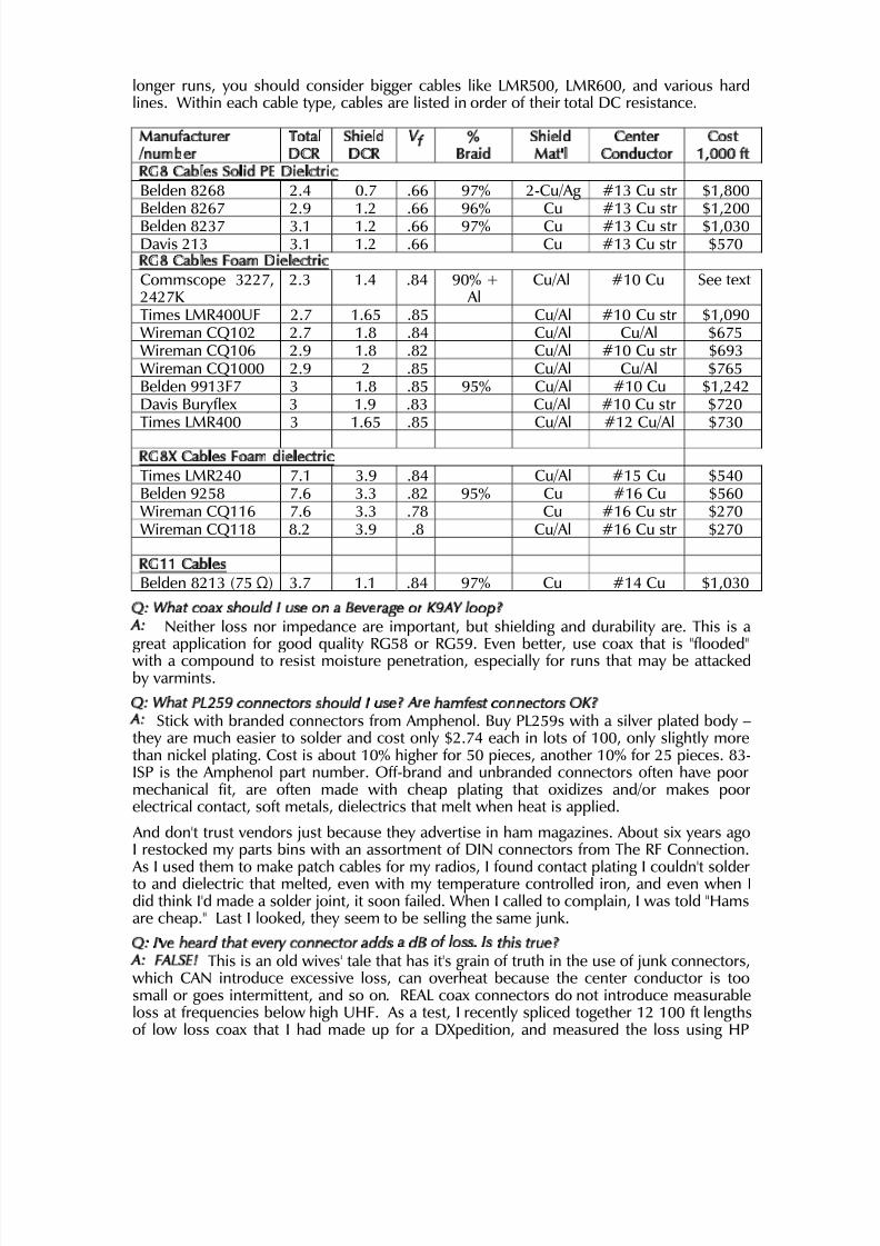
Q: What are some good types of coax for my HF station?A: The table below lists a known good cables with full published specifications fromknown good vendors. Costs listed are those I found with internet searches in Feb 2010from reputable vendors. Shorter lengths are more expensive per foot. Note that RG58 andRG59 are not on this list – they have too much loss for long runs, and their shielding is notas good as the larger cables. As I have time, I plan to add some RG6 cables to the list. For
8/3/2019 Coax Stubs
http://slidepdf.com/reader/full/coax-stubs 6/13
longer runs, you should consider bigger cables like LMR500, LMR600, and various hardlines. Within each cable type, cables are listed in order of their total DC resistance.
Manufacturer/number
TotalDCR
ShieldDCR
Vf %Braid
ShieldMat'l
CenterConductor
Cost1,000 ft
RG8 Cables Solid PE Dielctric Belden 8268 2.4 0.7 .66 97% 2-Cu/Ag #13 Cu str $1,800Belden 8267 2.9 1.2 .66 96% Cu #13 Cu str $1,200Belden 8237 3.1 1.2 .66 97% Cu #13 Cu str $1,030Davis 213 3.1 1.2 .66 Cu #13 Cu str $570RG8 Cables Foam DielectricCommscope 3227,2427K
2.3 1.4 .84 90% + Al
Cu/Al #10 Cu See text
Times LMR400UF 2.7 1.65 .85 Cu/Al #10 Cu str $1,090Wireman CQ102 2.7 1.8 .84 Cu/Al Cu/Al $675Wireman CQ106 2.9 1.8 .82 Cu/Al #10 Cu str $693Wireman CQ1000 2.9 2 .85 Cu/Al Cu/Al $765Belden 9913F7 3 1.8 .85 95% Cu/Al #10 Cu $1,242Davis Buryflex 3 1.9 .83 Cu/Al #10 Cu str $720Times LMR400 3 1.65 .85 Cu/Al #12 Cu/Al $730
RG8X Cables Foam dielectric Times LMR240 7.1 3.9 .84 Cu/Al #15 Cu $540Belden 9258 7.6 3.3 .82 95% Cu #16 Cu $560Wireman CQ116 7.6 3.3 .78 Cu #16 Cu str $270Wireman CQ118 8.2 3.9 .8 Cu/Al #16 Cu str $270
RG11 CablesBelden 8213 (75Ω) 3.7 1.1 .84 97% Cu #14 Cu $1,030
Q: What coax should I use on a Beverage or K9AY loop?A: Neither loss nor impedance are important, but shielding and durability are. This is agreat application for good quality RG58 or RG59. Even better, use coax that is "flooded"with a compound to resist moisture penetration, especially for runs that may be attackedby varmints.
Q: What PL259 connectors should I use? Are hamfest connectors OK?A: Stick with branded connectors from Amphenol. Buy PL259s with a silver plated body –they are much easier to solder and cost only $2.74 each in lots of 100, only slightly morethan nickel plating. Cost is about 10% higher for 50 pieces, another 10% for 25 pieces. 83-ISP is the Amphenol part number. Off-brand and unbranded connectors often have poormechanical fit, are often made with cheap plating that oxidizes and/or makes poorelectrical contact, soft metals, dielectrics that melt when heat is applied.
And don't trust vendors just because they advertise in ham magazines. About six years agoI restocked my parts bins with an assortment of DIN connectors from The RF Connection.
As I used them to make patch cables for my radios, I found contact plating I couldn't solderto and dielectric that melted, even with my temperature controlled iron, and even when Idid think I'd made a solder joint, it soon failed. When I called to complain, I was told "Hamsare cheap." Last I looked, they seem to be selling the same junk.
Q: I've heard that every connector adds a dB of loss. Is this true?A: FALSE! This is an old wives' tale that has it's grain of truth in the use of junk connectors,which CAN introduce excessive loss, can overheat because the center conductor is toosmall or goes intermittent, and so on. REAL coax connectors do not introduce measurableloss at frequencies below high UHF. As a test, I recently spliced together 12 100 ft lengthsof low loss coax that I had made up for a DXpedition, and measured the loss using HP

8/3/2019 Coax Stubs
http://slidepdf.com/reader/full/coax-stubs 7/13
equipment up to about 500 MHz. The total loss in that cable, including 24 PL259s and 11barrels was a dB or so less than the loss specified for the cable by the manufacturer at 500MHz. All connectors were Amphenols.
Using Stubs in Your HF StationQ: What's a Stub?A: A stub is simply a short length of transmission line connected in parallel with the coax
feeding an antenna. At the far end, the stub is terminated with either a short circuit or anopen circuit. In their simplest form, stubs that are some multiple of a quarter wavelengthare used to kill harmonics or sub-harmonics of the operating frequency. One property of atransmission line is that it inverts the impedance every quarter wavelength, so a quarter-wave stub with a short at one end looks like an open circuit at the other end. At the secondharmonic, that same stub is two quarter-waves long, so the short is inverted twice, andlooks like a short circuit to the harmonic. At the third harmonic, it's three quarter-waves, soit's an open circuit again, then at a full wavelength it's a short circuit again. Likewise, aquarter wave stub that is open at the far end looks like a short circuit, but an open circuit atthe second harmonic.
Q: When do we use shorted stubs?A: Shorted quarter-wave stubs are used to kill even-order harmonics (2nd, 4th, 6th, 8th).
For example, a shorted quarter-wave 80M stub passes 80M, but kills 40M, 20M, and 10M. A shorted quarter-wave stub for 40M passes 40M but kills 20M and 10M. Shorted stubsare both transmitting and receiving stubs – they kill harmonics of our transmitter, and theyalso reject signals on harmonically related bands received from nearby transmitters.
Q: What about open stubs?A: An open half-wave stub is primarily a receiving stub, used to minimize the receivedsignal from transmitters on bands below the one where we're listening. For example, ahalf-wave open 40M stub will look "open" on 40M, but will be a quarter-wave on 80M,look like a short, and attenuate the 80M fundamental by about 25dB.
Q: Why Use Stubs?A: Stubs can be used at the output of power amplifiers to attenuate harmonics; nearly allbandpass filters are rated for about 100 watts, so can be used only between the transceiver
and the power amp. Stubs also add to the filtering provided by dedicated band pass filters(ICE, Dunestar, W3NQN), or they can function as a "poor-man's band-stop filter." Properlyused, a stub can provide 20-30 dB of attenuation at one or more harmonically relatedfrequencies. The lower the loss of the cable used for the stub, the more attenuation itprovides.
Q: Does it matter where a stub is connected? Why?A: A stub works by placing a short circuit across the line at the frequency of interference.Placing a stub on a line forms a voltage divider between the line impedance and the stubimpedance. The higher the line impedance at the point of connection, the greater theattenuation. If the line is well matched at both ends, the position doesn't matter, becausethe impedance at every point along the line is the same. But if there's a mismatch, theimpedance will vary along the length of the line, and if the impedance at the location of the
stub is low, it won't be very effective.Q: If I connect a stub between my transmitter and my antenna tuner, isn't that a matchedline?A: Not at the frequency of the harmonic the stub is intended to suppress! All power ampsinclude output networks designed to suppress their harmonics. The right place for atransmitting stub depends mostly on what kind of output network your power amp uses. If you put the stub in the "right" place (that is, at a high impedance point), you get closer tothe full value of the stub's harmonic suppression. If you place it at a low impedance point,you may get little benefit from adding the stub.

8/3/2019 Coax Stubs
http://slidepdf.com/reader/full/coax-stubs 8/13
Q: How do I figure out what to do with my amp?A: See the table below, or study the manual for your amplifier. One common form of amplifier output network is the so-called pi-L – starting with the tube, there's a shuntcapacitor, a series inductor, a shunt capacitor, and an inductor in series with the feed tocoax connector. A pi-L network will have a fairly high output impedance at the frequency of the harmonic, so for these amps, any stub intended to short out a harmonic works bestright at the output terminals of the amp (or a half-wave away at the frequency of theharmonic). That same circuit, but without the last inductor, is called a pi-network (becauseit looks like the Greek letter pi). Many lower cost tube amps, and most solid state ampsuse either a pi-network or a multi-stage filter with a shunt capacitor at the output. Theseamps will have a low output impedance at the harmonic, so any stub intended to short outa harmonic should be placed one-quarter wavelength up the line from the output terminalsof the amp at the frequency of the harmonic (because the quarter-wavelength of linetransforms the low impedance to a high impedance). For example, a quarter-wave shortedstub on the output of a 40M power amp with a pi-network output should be at a distanceof 1/8 wavelength on 40M. When computing the length to move the stub, use the velocityfactor of the main transmission line, not the velocity factor of the stub.
Pi-L Network Pi-network or multiple-Pi Pi-L on 160/80, Pi other bandsPut stub at the amp Put stub λ /4 up the line at the
harmonicStub at the amp if operating on160/80, λ /4 away on other bands
Acom 1000, 1010 Commander HF-1250, HF-2500 Ameritron AL80, AL82, AL-1200
Alpha 374, 76, 77,87, 91B
Dentron Clipperton L,MLA-2500
Heath SB1000
Ameritron AL800H Drake L4, L7QRO 2500DX Elecraft KPA500Ten Tec Titan 425 Heath SB-200/SB201/SB-
220/SB-221Kenwood TL-922A Ten Tec Hercules II,Centurion
Thanks to W5IFP, W4TV, K6XX, and K1HI for adding amplifier models to the table.
Q: I have a set of bandpass filters. Do I also need stubs?
A: Maybe. Nearly all ham bandpass filters are designed for 100-200 watts in matched lines,so in a high power station, they must be placed between the transceiver and the poweramplifier. They protect the receiver from other nearby transmitters, but they can't reduceharmonics produced in your power amp. You could buy bandpass filters to go after thepower amp, but they are very expensive! It also depends on the quality of your bandpassfilters, how much power you're running, how much signal your receiver can tolerate, thespacing between your antennas, and their orientation. Some bandpass filters are muchbetter than others. W3NQN-designed filters are generally acknowledged as the best,Dunestar a bit behind them, and ICE at the low end. The owner of ICE recently became aSilent Key, and the filter business has been taken over by Morgan Manufacturing.
Q: Which coax works best for HF stubs?A: The best coax for HF stubs is one that combines low loss with a low velocity factor. Low
velocity factor means the stub will be shorter. Loss at HF is entirely the result of conductorresistance. It doesn't make sense to spend extra for a premium foam coax that offers lowloss at UHF – foam has a high velocity factor, so the stub must be longer to resonate.Beefy cables like Belden 8237, 8267, and 9251 are great for HF stubs. Coax with a foam PEdielectric will work, but you'll need 25%-30% more cable, and you'll need a #10 centerconductor with a heavy copper braid and heavy foil shield to be as good. Commscope3227 fits this bill, and is great cable if you can find it.
Q: What stubs do I need for a typical SO2R contesting station?A: A good start is outlined in the table below. It was developed many years ago by FredLass, K2TR.

8/3/2019 Coax Stubs
http://slidepdf.com/reader/full/coax-stubs 9/13
Band Stub(s)Approx Length
(Vf = 0.66)160 λ /4 Shorted stub to kill harmonic on 80/75M 89 ft80 λ /4 Shorted stub protects 40, 20, 15, 10 46 ft
λ /4 Shorted stub protects 20, 10 23 ftλ /2 Open stub kills harmonic from 80 46 ft
40:
λ /6Shorted stub
+ λ /12Open stub kills 15M harmonic 16 ft, 8 ftλ /4 wave Shorted stub protects 10 11.5 ft20
λ /2 Open stub protects 15 (3/4 on 15), kills 40M harmonic 23 ft15 3 λ /4 wave Shorted stub protects 20 and 10 (1/4 wave on
40M)23 ft
λ /2 wave Open stub protects RX from 20M 13 ft101 λ wave Open stub protects RX from 40M and 15M (λ /4wave on 40M)
23 ft
Note: All lengths are approximate. All stubs must be trimmed to length. See text.
Q: Can I measure a long spool of coax as a stub to find its length?A: Yes, but there's a bit more to the measurement than meets the eye. That's because thevelocity factor Vf is not a constant – it varies with frequency. The variation is small in the
HF spectrum, but, for many cables, can bequite significant at low radio frequencies. Vf starts out very low at audio frequencies, butquickly begins rising at low radio frequenciesuntil it settles at the familiar published value.The graph at the right is measured data forCommscope 3227, a high quality RG8 coaxialcable. The published Vf for this cable is 0.84.Measurements were made by connecting a full1,000 ft spool of cable as a stub in a precision50 ohm system and observing the frequency of the nulls. The quarter wave resonance was194.5 kHz. Additional nulls were measured up
to 3.8 MHz (19 quarter waves).To extend the measurement to higher frequencies, a 59 ft length of the cable was cut fromthe spool and measured as a stub in the same 50 ohm circuit, starting with its quarter waveresonance at 3.482 MHz, up to its 15 quarter wave resonance at 52.8 MHz. Because its 59ft length was known precisely, it was used to compute Vf, and the data for measurement of the entire spool was adjusted so that the data agreed at the frequency where both lengthswere measured. The two data sets were spliced together in the spreadsheet to get the fullcurve, and used to establish the actual length of the spool as 1,012 ft. The bump in thecurve at 1 MHz is almost certainly a bad data point.
Q: Your measured data is for coax with a foam dielectric. How about a solid dielectric?A: The variability of Vf is a fundamental property of all transmission lines. The onlydifference is the nominal (HF/VHF) value of Vf resulting from its dielectric and the
frequency at which the curve for that cable starts to flatten out to its nominal value. For atutorial discussion of this, see http://audiosystemsgroup.com/TransLines-LowFreq.pdf Youmay be surprised to learn from this tutorial that ZO also varies with frequency, and for thesame reasons! See also two excellent papers by Frank Witt, AI1H, in the ARRL AntennaCompendium Vol 6.
Q: Do I need to account for the variability of Vf when cutting a stub?A: It depends on the cable you're using for your stub, the frequency where the curve of Vf flattens out for your cable, and the frequency of your stubs. For the cable shown in thegraph, this would only be an issue on 160, 80, and 40M. Let's say you're building a shorted
8/3/2019 Coax Stubs
http://slidepdf.com/reader/full/coax-stubs 10/13
stub for 80M, and you don't know the variability of Vf for your cable. You would ordinarilycut the stub 5% long, then trim it to length by observing the null with an open circuit at thefundamental frequency, allowing about one-quarter inch or so extra length to trim andshort the end. To correct for the variability of Vf, simply trim the open stub for a null at thethird harmonic of the operating frequency rather than the fundamental! Now, when youshort the stub, the null at the second harmonic is likely to be exactly where you want it.
Q: What's the best way to measure a stub?
A: Connect a 50 ohm generator to a 50 ohm receiver, placing a Tee connector in line.Connect the Male output of the Tee to the receiver, use any convenient length of 50 ohmcable to connect the generator to one female end of the Tee, connect the stub to theremaining female end.
Q:How do I kill the 3rd harmonic of 40M on 15M?A: In his book (referenced above) George Cutsageorge, W2VJN, describes a number of very useful double-stub solutions. One of them, also described by Ward Silver, N0AX, inNov 2007 QST, solves this problem quite neatly. At the same point on the line, insert twostubs – one a λ /6 Shorted stub and the other a λ /12 Open stub. On 40M, the Shorted stublooks like 86.6Ω of inductive reactance, and the Open stub looks like an equal value of capacitive reactance, so they cancel and are invisible on 40M. But at the third harmonic(15M), the Shorted stub is λ /2 and the Open stub is λ /4, so both stubs look like short
circuits and null the harmonic.To trim the λ /12 Open stub, you simply look for the null on 15M. To trim the λ /6 stub, trimit where it is λ /4 (at 10.5 MHz), cut it 1/4-inch long, and then short it.
Q: What's the best way to add a stub to a transmission line? A: At the desired junction point in the line, connect one side of the junction to one femaleend of the Tee, connect the other side of the junction to the Male output of the Tee (a coaxbarrel is required) and connect the stub to the other female end of the Tee.
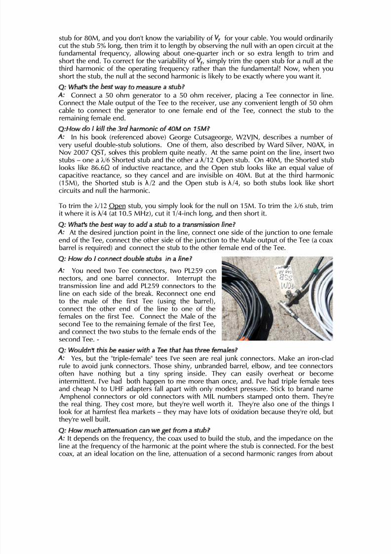
Q: How do I connect double stubs in a line?
A: You need two Tee connectors, two PL259 connectors, and one barrel connector. Interrupt thetransmission line and add PL259 connectors to theline on each side of the break. Reconnect one endto the male of the first Tee (using the barrel),connect the other end of the line to one of thefemales on the first Tee. Connect the Male of thesecond Tee to the remaining female of the first Tee,and connect the two stubs to the female ends of thesecond Tee. -
Q: Wouldn't this be easier with a Tee that has three females?A: Yes, but the "triple-female" tees I've seen are real junk connectors. Make an iron-cladrule to avoid junk connectors. Those shiny, unbranded barrel, elbow, and tee connectorsoften have nothing but a tiny spring inside. They can easily overheat or becomeintermittent. I've had both happen to me more than once, and. I've had triple female tees
and cheap N to UHF adapters fall apart with only modest pressure. Stick to brand name Amphenol connectors or old connectors with MIL numbers stamped onto them. They'rethe real thing. They cost more, but they're well worth it. They're also one of the things Ilook for at hamfest flea markets – they may have lots of oxidation because they're old, butthey're well built.
Q: How much attenuation can we get from a stub?A: It depends on the frequency, the coax used to build the stub, and the impedance on theline at the frequency of the harmonic at the point where the stub is connected. For the bestcoax, at an ideal location on the line, attenuation of a second harmonic ranges from about

8/3/2019 Coax Stubs
http://slidepdf.com/reader/full/coax-stubs 11/13
20dB from a 160M transmitter to 30dB or more on 10M. The null depth of a stub at itsfirst resonance is approximately proportional to frequency. The table summarizes best caseperformance of stubs made with good quality solid PE RG8.
Frequency λ /4 Open λ /2 Shorted, 2nd Harm160M 18-21 dB80M 20-23 dB 23-27 dB40M 23-26 dB 25-27 dB20M 26-29 dB 26-29 dB10M 28-30 dB
A few years ago, I measured a random collection of stubs that I built from a variety of cables for various ham bands. My test set was the HP generator/calibrated voltmeter rigdescribed above for fine-tuning stubs and measuring VF. Here are the results.

8/3/2019 Coax Stubs
http://slidepdf.com/reader/full/coax-stubs 12/13
Q: Where can I learn more about stubs?A: The newest ARRL Handbook has a very good introduction to stubs, and covers use of these simple stubs to solve harmonic problems. It was written by W2VJN, whose self-published book "Managing Interstation Interference" goes into far greater detail, and haslong been considered "the Bible" for hams designing multi-transmitter stations. It covers alot more than stubs, and it also shows how to build multi-element stub filters that providemuch greater attenuation, and to filter bands that can't be tackled with the simple stubs
described here! Buy it from Inrad (the filter people) for $20. They're selling the latestedition, and you want it, because it includes additional techniques and designs that areworth knowing about. Ward Silver, N0AX, has written four very nice pieces on stubs forhis excellent "Hands-On Radio" series in QST. They were published in Nov 2004, Oct andNov 2007, and Jan 2008.

8/3/2019 Coax Stubs
http://slidepdf.com/reader/full/coax-stubs 13/13
These drawings, from K1TTT's website, illustrating K2TR's stub recommendations,assuming cable with a 0.66 velocity factor. Take these lengths as starting points, cuttingthem a bit long and carefully trimming to length using one of the methods noted above.
![qudev.phys.ethz.ch · (b) 500nm 100 m . Gate Charge, ng [e] 40 30 2 20 Gate Charge, ng [e] coax . coax coax coax coax coax . probe 2 serv Control probe I ate 1 Target microwave coupler](https://img.dokumen.tips/doc/110x75/5f07545e7e708231d41c725e/qudevphysethzch-b-500nm-100-m-gate-charge-ng-e-40-30-2-20-gate-charge.jpg)