Embed Size (px)
Citation preview

CO2 capture from oxy-fuel combustion power plants
Yukun Hu
Licentiate Thesis
2011
KTH Royal Institute of Technology School of Chemical Science and Engineering
Department of Chemical Engineering and Technology Energy Processes
Stockholm, Sweden

Cover image created by Belle Mellor.
Copyright © Yukun Hu 2011
All rights reserved
TRITA-CHE Report 2011:52
ISSN 1654-1081
ISBN 978-91-7501-140-0

I
Abstract
To mitigate the global greenhouse gases (GHGs) emissions, carbon dioxide (CO2) capture and
storage (CCS) has the potential to play a significant role for reaching mitigation target. Oxy-fuel
combustion is a promising technology for CO2 capture in power plants. Advantages compared to
CCS with the conventional combustion technology are: high combustion efficiency, flue gas
volume reduction, low fuel consumption, near zero CO2 emission, and less nitrogen oxides (NOx)
formation can be reached simultaneously by using the oxy-fuel combustion technology. However,
knowledge gaps relating to large scale coal based and natural gas based power plants with CO2
capture still exist, such as combustors and boilers operating at higher temperatures and design of
CO2 turbines and compressors. To apply the oxy-fuel combustion technology on power plants,
much work is focused on the fundamental and feasibility study regarding combustion
characterization, process and system analysis, and economic evaluation etc. Further studies from
system perspective point of view are highlighted, such as the impact of operating conditions on
system performance and on advanced cycle integrated with oxy-fuel combustion for CO2 capture.
In this thesis, the characterization for flue gas recycle (FGR) was theoretically derived based on
mass balance of combustion reactions, and system modeling was conducted by using a process
simulator, Aspen Plus. Important parameters such as FGR rate and ratio, flue gas composition,
and electrical efficiency etc. were analyzed and discussed based on different operational
conditions. An advanced evaporative gas turbine (EvGT) cycle with oxy-fuel combustion for
CO2 capture was also studied. Based on economic indicators such as specific investment cost
(SIC), cost of electricity (COE), and cost of CO2 avoidance (COA), economic performance was
evaluated and compared among various system configurations. The system configurations include
an EvGT cycle power plant without CO2 capture, an EvGT cycle power plant with chemical
absorption for CO2 capture, and a combined cycle power plant.
The study shows that FGR ratio is of importance, which has impact not only on heat transfer but
also on mass transfer in the oxy-coal combustion process. Significant reduction in the amount of
flue gas can be achieved due to the flue gas recycling, particularly for the system with more prior
upstream recycle options. Although the recycle options have almost no effect on FGR ratio, flue
gas flow rate, and system electrical efficiency, FGR options have significant effects on flue gas
compositions, especially the concentrations of CO2 and H2O, and heat exchanger duties. In
addition, oxygen purity and water/gas ratio, respectively, have an optimum value for an EvGT
cycle power plant with oxy-fuel combustion. Oxygen purity of 97 mol% and water/gas ratio of
0.133 can be considered as the optimum values for the studied system. For optional operating
conditions of flue gas recycling, the exhaust gas recycled after condensing (dry recycle) results in
about 5 percentage points higher electrical efficiency and about 45 % more cooling water
consumption comparing with the exhaust gas recycled before condensing (wet recycle). The
direct costs of EvGT cycle with oxy-fuel combustion are a little higher than the direct costs of
EvGT cycle with chemical absorption. However, as plant size is larger than 60 MW, even though
the EvGT cycle with oxy-fuel combustion has a higher COE than the EvGT cycle with chemical
absorption, the EvGT cycle with oxy-fuel combustion has a lower COA. Further, compared with
others studies of natural gas combined cycle (NGCC), the EvGT system has a lower COE and
COA than the NGCC system no matter which CO2 capture technology is integrated.

CO2 capture form oxy-fuel combustion power plants
II
Keywords: CO2 capture; oxy-fuel combustion; flue gas recycle; evaporative gas turbine; techno-
economic evaluation.
Language: English
III
Acknowledgments
First of all, I would like to express my appreciation to my supervisor Professor Jinyue Yan for his
encouraging and stimulating guidance during the work with this thesis. Your rigorous academic
approach will benefit me throughout my life. I am also grateful to Dr. Jinying Yan and
Dr. Hailong Li for their useful ideas and tremendous help.
I am honored as one of the PhD students in the division of Energy Processes. Lovely professors
and colleagues, you made me no longer cold in Stockholm’s winter. Especially, my office mate,
Mr. Johannes Persson, your humor and wit made my research life more fun. Additionally, all my
Chinese friends in Sweden are appreciated here for their help over these years.
I gratefully acknowledge China Scholarship Council for providing me financial support and help
from the Education section of the Chinese Embassy in Sweden. Because both of you, I do feel
the meticulous care from my motherland.
I do wish to thank Professor Jing Ding at my home university in China. You offered me this
cherished chance to study in Sweden, being your student was a very rewarding experience.
Finally, I am deeply indebted to my family. Your silent support is the power source to my road
ahead. It is really great having all of you in my life.
Yukun Hu
Stockholm, October 2011

IV

V
List of Appended Papers
This thesis is based on the following papers, referred to by Roman numbers I-IV. The papers are
appended at the end of the thesis.
I. Hu Y., Yan J., 2011. Characterization of flue gas in oxy-coal combustion processes for CO2
capture. Applied Energy, doi: 10. 1016/j.apenergy.2011.03.005.
II. Hu Y., Yan J., Li H., 2011. Effects of flue gas recycle on the performance of particles, SOx
and NOx removal in oxy-coal power generation system. International Conference on
Applied Energy, Perugia, Italy, May 16-18.
III. Hu Y., Li H., Yan J., 2010. Integration of evaporative gas turbine with oxy-fuel combustion
for carbon dioxide capture. International Journal of Green Energy 7, 615-631.
IV. Hu Y., Li H., Yan J., 2012. Techno-economic evaluation of the evaporative gas turbine
cycles combined with different CO2 capture techniques. Applied Energy 89: 303-314.
Other publications which are not included in this thesis:
V. Hu Y., Yan J., Li H. Effects of flue gas recycle on oxy-coal power generation system.
Applied Energy, under review.
VI. Li H., Flores S., Hu Y., Yan J., 2009. Simulation and optimization of evaporative gas turbine
with chemical absorption for carbon dioxide capture. International Journal of Green Energy
6, 527-539.
My contribution to the appended papers Papers I, II, III, IV, and V are the continuous work of the previous studies. The basic concepts
and ideas are from the supervisors/co-authors. I did the specific tasks and wrote the first draft of
the papers. Co-authors made valuable revision to improve the drafts. Additionally, I am a co-
author of Paper VI, in which I did validation of the simulation.

VI

VII
Table of Contents
Abstract .................................................................................................................................................... I
Acknowledgments ................................................................................................................................ III
List of Appended Papers ...................................................................................................................... V
Table of Contents .............................................................................................................................. VII
List of Figures ...................................................................................................................................... IX
List of Tables ........................................................................................................................................ XI
Abbreviations and Nomenclatures .................................................................................................. XIII
1. Introduction ....................................................................................................................................... 1
1.1. Background ........................................................................................................................................ 1
1.2. Previous studies ................................................................................................................................. 2
1.2.1. Combustion characterization ................................................................................................... 3
1.2.2. Process and system analysis ..................................................................................................... 4
1.2.3. Techno-Economic evaluation ................................................................................................. 5
1.3. Problem description ......................................................................................................................... 6
1.4. Objective of this study ..................................................................................................................... 7
1.5. Thesis outline .................................................................................................................................... 7
2. Studied systems .................................................................................................................................. 9
2.1. Reference systems and subsystems ................................................................................................ 9
2.1.1. Conventional pulverized coal power plant ............................................................................ 9
2.1.2. Evaporative gas turbine (EvGT) cycle ................................................................................. 10
2.1.3. Air separation unit (ASU) ....................................................................................................... 10
2.1.4. CO2 conditioning process ...................................................................................................... 11
2.2. Oxy-combustion systems............................................................................................................... 12
2.2.1. Oxy-coal power plant with CO2 capture .............................................................................. 12
2.2.2. Oxy-EvGT cycle power plant with CO2 capture ................................................................ 12
3. Methodology .................................................................................................................................... 15
3.1. Oxy-coal combustion system ........................................................................................................ 15
3.1.1. Combustion parameters ......................................................................................................... 15
3.1.2. System modeling ...................................................................................................................... 15
3.2. Oxy-fuel EvGT system .................................................................................................................. 18
3.2.1. System modeling ...................................................................................................................... 18
3.2.2. Economic evaluation .............................................................................................................. 19
4. Results and discussions ................................................................................................................... 21

CO2 capture form oxy-fuel combustion power plants
VIII
4.1. Mass and energy balances of the oxy-coal combustion process .............................................. 21
4.1.1. Theoretical analysis of flue gas recycle (FGR) .................................................................... 21
4.1.2. Simulation of oxy-coal combustion process ........................................................................ 23
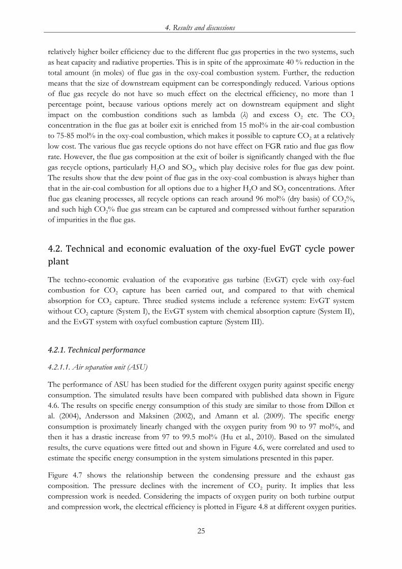
4.2. Technical and economic evaluation of the oxy-fuel EvGT cycle power plant ..................... 25
4.2.1. Technical performance ........................................................................................................... 25
4.2.2. Economic performance .......................................................................................................... 28
5. Conclusions ...................................................................................................................................... 31
6. Future work ...................................................................................................................................... 33
7. References ........................................................................................................................................ 35

IX
List of Figures
Figure 1.1 Strategy to reduce global CO2 .................................................................................................. 1
Figure 1.2 Overview of CO2 capture approaches .................................................................................... 2
Figure 1.3 Schematic diagram of the thesis structure ............................................................................. 7
Figure 2.1 Schematic diagram of a conventional pulverized coal power plant ................................... 9
Figure 2.2 Schematic diagram of the EvGT cycle ................................................................................. 10
Figure 2.3 Schematic diagram of ASU .................................................................................................... 11
Figure 2.4 Schematic diagram of the CO2 conditioning process ......................................................... 11
Figure 2.5 Schematic diagram of flue gas subsystem in the oxy-coal combustion system .............. 12
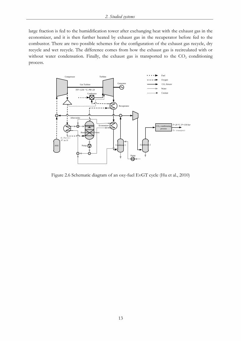
Figure 2.6 Schematic diagram of an oxy-fuel EvGT cycle ................................................................... 13
Figure 3.1 Illustration of combustion parameters of oxy-fuel combustion ....................................... 15
Figure 3.2 Flow sheet of the oxy-coal combustion process ................................................................. 16
Figure 3.3 Simulation model of the humidification tower ................................................................... 19
Figure 4.1 Effect of O2 concentration of oxidant on flue gas recycle rate ........................................ 22
Figure 4.2 Effect of O2 contained in recycled flue gas on flue gas recycle rate ................................ 23
Figure 4.3 Effect of stoichiometric coefficients of O2 (ν) on flue gas recycle rate ........................... 23
Figure 4.4 Effect of moisture in coal on flue gas recycle ratio ............................................................ 24
Figure 4.5 Effect of lambda (λ) on flue gas recycle ratio ...................................................................... 24
Figure 4.6 Specific energy consumption of ASU at different oxygen purity ..................................... 26
Figure 4.7 Minimum condensing pressure of CO2 stream at different oxygen purity ..................... 26
Figure 4.8 Electrical efficiency of oxy-fuel EvGT cycle at different oxygen purity ......................... 26
Figure 4.9 Electrical efficiency at different W/G .................................................................................. 27
Figure 4.10 Stack temperature and humid gas temperature after recuperator at different W/G ... 27
Figure 4.11 Effect of plant size on specific direct field costs in $/kW price of different cycles ... 28
Figure 4.12 Effect of plant size on cost of electricity (COE) .............................................................. 29
Figure 4.13 Effect of plant size on cost of CO2 avoidance (COA) .................................................... 29

X

XI
List of Tables
Table 3.1 Specification and description of unit operation blocks ....................................................... 16
Table 3.2 Specifications of the reactions in SCR and FGD ................................................................. 16
Table 3.3 Input data and assumptions for the oxy-coal combustion system .................................... 17
Table 3.4 Input data and assumptions for the simulation of oxy-fuel EvGT system ...................... 18
Table 3.5 Assumptions made in the cost calculation ............................................................................ 20
Table 4.1 Summary of system simulation results ................................................................................... 24
Table 4.2 Comparison between dry recycle and wet recycle ................................................................ 27
Table 4.3 Comparison on system parameters and economic parameters of different systems ...... 30

XII

XIII
Abbreviations and Nomenclatures Abbreviations: ASU Air separation unit
AIC Amortized investment costs
APH Air preheater
BMC Bare module costs
CC Combined cycle
CCS CO2 capture and storage
CEPCI Chemical engineering’s plant cost index
CF Capacity factor
COA Cost of CO2 avoidance
COE Cost of electricity
ESP Electrostatic precipitator
EvGT Evaporative gas turbine
FC Fuel cost
FCF Fixed charge factor
FGC Flue gas condenser
FGD Flue gas desulfurization
FGR Flue gas recycle
FOB Free on board
FOM Fixed operating & maintenance costs
GHGs Greenhouse gases
HAT Humid air turbine
HGT Humid gas temperature after recuperator
HPC High pressure column
IR Interest rate
LHV Lower heating value
LPC Low pressure column
NGCC Natural gas combined cycle
PG Power generation
PR Primary recycle
SCR Selective catalytic reduction
SIC Specific investment cost
SPH SCR preheater
SR Secondary recycle
TEG Triethylene glycol
TIC Total investment costs
VOM Variable operating & maintenance costs
W/G Water/Gas ratio

CO2 capture form oxy-fuel combustion power plants
XIV
Nomenclatures: P Pressure, bar
Q Heat, J
T Temperature, °C
W Work, W
Y Operating life, year
δ Stoichiometric coefficient of product
η Dust removal efficiency
ε Excess O2
λ Stoichiometric ratio
ν Stoichiometric coefficient of O2

1
1. Introduction
1.1. Background
Global warming caused by greenhouse gases (GHGs) has been recognized as a worldwide issue.
The global average temperature has been increased by 0.74 K since the late 1800s, and would
cause further warming by continued GHGs emission at or above current rates by the end of the
21st century (IPCC, 2007). GHGs, for example, carbon dioxide (CO2), methane (CH4) and nitrous
oxide (N2O), emissions have a long-term influence on climate change. The largest contributor
amongst GHGs is CO2, accounting for half the greenhouse effect (Myers, 1989), and the major
source of it is the combustion of fossil fuels to supply energy (Quadrelli and Peterson, 2007).
Fossil fuels are predicted to be the main energy sources during the next decades (EIA, 2009).
According to the International Energy Agency (IEA, 2008), coal is currently the dominant fuel in
the power sector, whilst natural gas generation becomes the second largest source, surpassing
hydro, accounting for 41 % and 20 % of electricity generated respectively. The need to reduce
anthropogenic emissions of CO2 is globally agreed and represents the driving force to reconsider
the current technologies used for power generation.
CO2 capture and storage (CCS), which involves capture, transport and long-term storage of CO2,
is now widely recognized as one of feasible methods that could contribute significantly to the
reduction of CO2 emissions. CCS is a critical technology amongst a serial of measures to limit
climate change to a manageable level, along with improving the efficiency of energy conversion
and/or utilization, and switching to renewable energy resources. It was reported that it is possible
for the European electricity generation system to meet an 85 % CO2 reduction target by 2050
with a potentially large contribution from CCS (Odenberger and Johnsson, 2010). The
importance of CCS has been highlighted in Figure 1.1 as one of the key elements in the strategy
of reducing greenhouse gas emissions.
Figure 1.1 Strategy to reduce global CO2 (Stangeland, 2007)
At present, power plants and other large-scale industrial processes, like cement and steel
production etc., are the primary candidates for CO2 capture. There are three main approaches to
CO2 capture: post-combustion capture, oxy-fuel combustion (or O2/CO2 recycle combustion)
and pre-combustion capture, which can be envisaged in Figure 1.2:

CO2 capture form oxy-fuel combustion power plants
2
Post-combustion capture: to capture CO2 from flue/exhaust gases by means of chemical
absorption process.
Oxy-fuel combustion capture: a fuel is combusted with oxygen in nitrogen free
environment to produce a flue/exhaust gas consisting essentially of CO2 and water. The
CO2 can be stored with less downstream processing.
Pre-combustion capture: to capture CO2 from synthesis gas after conversion of CO into
CO2, then H2 is used as the fuel in a gas turbine combine cycle or applications.
Figure 1.2 Overview of CO2 capture approaches (IPCC, 2005) Amongst these technologies, oxy-fuel combustion is becoming a highly interesting option for
CO2 capture due to the possibility to use the advanced steam technology, reduce equipment size
and cost and to design a zero-emission power plant (Jordal et al., 2004).
The concept of oxy-fuel combustion has been firstly evaluated by Abraham et al. (1982) for
enhanced oil recovery in the early eighties, which is characterized by the combustion that takes
place in oxygen rich environment rather than air with recycled flue gas. Due to the high cost of
oxygen production using the cryogenic air separation technology in early days of this technology,
the oxy-fuel combustion was originally developed only for special high-flame-temperature
applications in which air-fuel combustion was not applicable. Since air separation technologies
have been improved to reduce the cost of oxygen production and the key issue of CO2 capture
was drawing more attention, oxy-fuel combustion can be widely used in industry. However,
conceptual designs for such applications are still in the research phase.
1.2. Previous studies
As one of the research interests in our group, R&D and pilot test on evaporative gas turbines
(EvGT) or humid air turbine (HAT) had been conducted in system integration for higher
efficiency. (Bartlett, 2002; Jonsson and Yan, 2001, 2002a, 2002b, 2003; Maunsbach et al., 2001;

1. Introduction
3
Wolf et al., 2002; Yan and Eidensten, 2000; Jonsson and Yan, 2005), development of associated
property models of water-air mixtures (Ji and Yan, 2003, 2006; Ji et al., 2003a, 2003b, 2004). In
recent years, Li and Yan (Li and Yan, 2009; Li et al., 2009a; Li et al., 2009b) predicted impurity
impacts on thermodynamic properties of CO2-streams in the purification process of oxy-fuel
combustion based CCS system from the energy consumption point of view, and made a
performance comparison on the EvGT systems with oxy-fuel combustion and post-combustion.
The results showed that the presence of non-condensable gases makes condensation more
difficult and results in the increased condensing pressure of CO2-streams.
To improve the technology of oxy-fuel combustion as well as its application, many efforts have
been focused on the fundamental and feasibility study regarding combustion characterization,
process and system analysis, and economic evaluation etc., especially the understanding of the
differences between oxy-fuel combustion and air-fuel (conventional) combustion arising from the
change of combusting environment.
1.2.1. Combustion characterization
Combustion mechanism, radiative and convective heat transfer, impurity prediction have been
widely investigated to identify the combustion characterization of the oxy-fuel combustion
process including combustion mechanism, heat transfer, impurity formation. Previous studies are
summarized as following.
Combustion mechanism: A fundamental investigation on the combustion of single particles of
different coals and synthetic chars has been conducted by Bejarano and Levendis (2008).
Experimental results revealed that coal particles burned at higher mean temperatures and shorter
combustion times in air-fuel combustion than oxy-fuel combustion at similar oxygen
concentrations. Fuel burnout is delayed for the oxy-fuel combustion compared with the air-fuel
combustion as a consequence of reduced temperature levels. A higher oxygen concentration
yields shorter ignition delay and devolatilization times through its effect on the local mixture
reactivity. CO2 decreases the rate of devolatilization, whereas higher O2 concentrations increase
the mass flux of oxygen to the volatiles flame (Shaddix and Molina, 2009). Krishnamurthy et al.
(2009) compared “flame” and “flameless” oxy-fuel combustion, and concluded that “flameless”
oxy-fuel combustion can be achieved by the asymmetric injection of high velocity oxygen,
meanwhile, which results in a more uniform temperature and total heat flux distribution.
Heat transfer: Solution methods for radiative transfer equation in gaseous oxy-fuel combustion
environments indicated that using gray method for the radiative properties may cause errors on
calculation of heat flux and should be avoided (Porter et al., 2010). Peak radiative heat flux values
are inversely related to recycle ratio. Conversely, convective heat flux values increase with
increasing recycle ratio (Smart et al., 2010a; Smart et al., 2010b). The O2 concentration in the
O2/CO2 mixture has to be 27 % to produce a similar combustion behavior compared to the air-
fuel combustion in terms of in-flame temperature and gas concentration levels (Liu et al. (2005b)
indicated this value is 30 % or even higher), but with significantly increased flame radiation
intensity (Andersson and Johnsson, 2007; Andersson et al., 2008; Li et al., 2009c). Flame
propagation velocity of pulverized coal cloud in oxy-fuel combustion decreases to about 1/3–1/5
CO2 capture form oxy-fuel combustion power plants
4
of that in air-fuel combustion at the same oxygen concentration. Reduction of flame stability in
oxy-fuel combustion is mainly due to the larger heat capacity of CO2 (Suda et al., 2007).
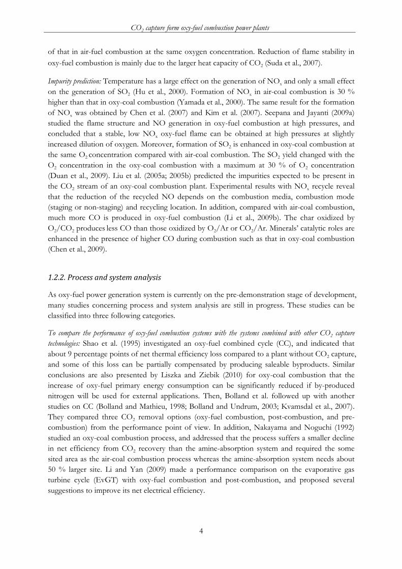
Impurity prediction: Temperature has a large effect on the generation of NOx and only a small effect
on the generation of SO2 (Hu et al., 2000). Formation of NOx in air-coal combustion is 30 %
higher than that in oxy-coal combustion (Yamada et al., 2000). The same result for the formation
of NOx was obtained by Chen et al. (2007) and Kim et al. (2007). Seepana and Jayanti (2009a)
studied the flame structure and NO generation in oxy-fuel combustion at high pressures, and
concluded that a stable, low NOx oxy-fuel flame can be obtained at high pressures at slightly
increased dilution of oxygen. Moreover, formation of SO2 is enhanced in oxy-coal combustion at
the same O2 concentration compared with air-coal combustion. The SO2 yield changed with the
O2 concentration in the oxy-coal combustion with a maximum at 30 % of O2 concentration
(Duan et al., 2009). Liu et al. (2005a; 2005b) predicted the impurities expected to be present in
the CO2 stream of an oxy-coal combustion plant. Experimental results with NOx recycle reveal
that the reduction of the recycled NO depends on the combustion media, combustion mode
(staging or non-staging) and recycling location. In addition, compared with air-coal combustion,
much more CO is produced in oxy-fuel combustion (Li et al., 2009b). The char oxidized by
O2/CO2 produces less CO than those oxidized by O2/Ar or CO2/Ar. Minerals’ catalytic roles are
enhanced in the presence of higher CO during combustion such as that in oxy-coal combustion
(Chen et al., 2009).
1.2.2. Process and system analysis
As oxy-fuel power generation system is currently on the pre-demonstration stage of development,
many studies concerning process and system analysis are still in progress. These studies can be
classified into three following categories.
To compare the performance of oxy-fuel combustion systems with the systems combined with other CO2 capture
technologies: Shao et al. (1995) investigated an oxy-fuel combined cycle (CC), and indicated that
about 9 percentage points of net thermal efficiency loss compared to a plant without CO2 capture,
and some of this loss can be partially compensated by producing saleable byproducts. Similar
conclusions are also presented by Liszka and Ziebik (2010) for oxy-coal combustion that the
increase of oxy-fuel primary energy consumption can be significantly reduced if by-produced
nitrogen will be used for external applications. Then, Bolland et al. followed up with another
studies on CC (Bolland and Mathieu, 1998; Bolland and Undrum, 2003; Kvamsdal et al., 2007).
They compared three CO2 removal options (oxy-fuel combustion, post-combustion, and pre-
combustion) from the performance point of view. In addition, Nakayama and Noguchi (1992)
studied an oxy-coal combustion process, and addressed that the process suffers a smaller decline
in net efficiency from CO2 recovery than the amine-absorption system and required the some
sited area as the air-coal combustion process whereas the amine-absorption system needs about
50 % larger site. Li and Yan (2009) made a performance comparison on the evaporative gas
turbine cycle (EvGT) with oxy-fuel combustion and post-combustion, and proposed several
suggestions to improve its net electrical efficiency.

1. Introduction
5
To improve the system performance by optimal design and analysis: Kakaras et al. (2007b) made an oxy-fuel
boiler design and compared to a conventional air-fuel boiler. It was found that the dominating
factors that affect the dimensioning of the oxy-fuel boiler are the higher radiative heat transfer
and the different flue gas mass flow. Seepana and Jayanti (2009b) optimized the enriched CO2
recycle oxy-fuel combustion for high ash coals. The thermodynamic exergy analysis showed that
the optimized CO2-enriched flue gas recycled power plant has 1.6 % higher thermal efficiency
than retrofitted flue gas recycled plant. Amann et al. (2009) investigated the modification of a
natural gas combined cycle power plant into an oxy-fuel combustion cycle for CO2 capture, and
pointed out that the conversion into an oxy-fuel combustion cycle seems to be more efficient
than amine scrubbing but more difficult to implement because of the specific gas turbine. In
addition, Li et al. (2009b) predicted impurity impacts on thermodynamic properties of CO2-
streams in the purification process of oxy-fuel combustion based CO2 capture and storage system
from the energy consumption point of view. The results showed that the increments of
impurities will make the energy consumption of purification increase, and make CO2 purity of
separation product and CO2 recovery rate decrease. Liu and Shao (2010) also predicted the
impurities expected to be present in the CO2 stream of an oxy-coal combustion plant.
To improve the system performance by innovative methods: Hong et al. (2009) analyzed the oxy-fuel
combustion power cycle utilizing a pressurized coal combustor, and indicated that this approach
recovers more thermal energy from the flue gas because the elevated flue gas pressure raises the
dew point and the available latent enthalpy of the flue gase. Pfaff and Kather (2009), Stadler et al.
(2011) made an analysis on oxy-coal plants with membrane based air separation. The result
showed that the membrane based air separation has comparable efficiency potentials, whereas it
needs a higher degree of integration into the power cycle to compete efficiencies of the power
cycle with the cryogenic based air separation. Then, Burdyny and Struchtrup (2010) examined the
process of hybrid membrane/cryogenic separation of oxygen from air for oxy-fuel combustion,
and found that the hybrid system is more productive in small to medium scale applications than
in large scale applications. Furthermore, Fiaschi et al. (2009) investigated the performance of an
oxy-fuel combustion CO2 power cycle including blade cooling in gas turbine. The results show
that the penalty in efficiency due to the blade cooling is about 1.4 percentage points, which, on
the other hand, leads to an improvement in specific work of about 6 %. White et al. (2010)
proposed that SOx and NOx components can be removed during compression of raw CO2
stream and therefore traditional flue gas deSOx and deNOx systems should not be required in an
oxy-coal power plant.
1.2.3. Techno-economic evaluation
Economic viability is the key point to promote one kind of innovation technology. Costs of CCS
technologies depend on many factors: fuel prices, capital cost, operating and maintenance costs
etc. Although the costs involve greater uncertainty compared to the technical related aspect,
many studies have been made to evaluate if oxy-fuel combustion fits into greenhouse gas
mitigation options on power plants or not.
Singh et al. (2003) made a techno-economic study of CO2 capture from an existing coal-fired
power plant adopting MEA scrubbing (post-combustion capture) and O2/CO2 recycle

CO2 capture form oxy-fuel combustion power plants
6
combustion. The results showed that both processes are expensive options to capture CO2 from
coal power plants. However, O2/CO2 recycle combustion appears to be a more attractive retrofit
than MEA scrubbing due to a lower CO2 emission. Ekström et al. (2009) also made techno-
economic evaluations and benchmarking of the pre-combustion CO2 capture and the oxy-fuel
process developed in the European ENCAP project. The project aimed at developing cost
efficient pre-combustion CO2 capture and oxy-fuel technologies for fossil fuels based power
generation systems, to substantially reduce the cost of CO2 capture. Zanganeh et al. (2005)
compared the refinery fuel gas oxy-fuel combustion options for CO2 capture using simulated
process data. This study showed that oxy-fuel combustion is a possible and viable approach for
CO2 capture from refinery fuel gases. A cost analysis was also performed to find out the
estimated CO2 capture and avoidance costs for each case. The CO2 avoidance cost was found to
be approximately 3 to 4.5 US cents per kg of CO2, excluding the transport and storage costs.
Kakaras et al. (2007a) examined and evaluated the application of the oxyfuel combustion CO2
capture technology in a lignite-fired power plant. The operational characteristics, the efficiency
penalties as well as the net efficiency reduction emerging from the Greenfield application of the
oxy-fuel technology are presented. In addition, Rezuani et al. (2009), Dillon et al. (2005a), and
Nsakala et al. (2003) compared different cycles with oxy-fuel combustion from economic point
of view.
For more information about oxy-fuel combustion, please refer to some comprehensive reviews
(Wall, 2007; Wall et al., 2009; Edge et al., 2011; Toftegaard et al., 2010; Kanniche et al., 2009;
Normann et al., 2009; Stanger and Wall, 2011; Koornneef et al., 2010; Buhre et al., 2005), and
technical reports (Dillon et al., 2005b; IEA, 2005; Rubin et al., 2007).
1.3. Problems description
There are several technical issues that need to be further studied to improve the oxy-fuel
combustion and its applications, e.g., the integration of evaporative gas turbine (EvGT) cycle
with oxy-fuel combustion and its performance analysis
Whether the combustion parameters defined in the traditional way for air-fuel
combustion processes are still appropriate to describe oxy-fuel combustion processes due
to the change of combustion environment?
Compared with air-fuel combustion processes, what are the special operating parameters
of oxy-fuel combustion processes, and how do they affect the combustion processes
under different operating conditions?
What are the main considerations when retrofitting an existing power plant or designing a
new cycle system with oxy-fuel combustion for CO2 capture? For example, flue gas
recycle amount, O2 concentration in oxidizer, dry/wet recycle, impact of impurities, and
system boundary conditions etc.

1. Introduction
7
How is the performance of the EvGT cycle integrated with oxy-fuel combustion for CO2
capture from techno-economic point of view, such as electrical efficiency, cost of
electricity (COE), and cost of CO2 avoidance (COA)?
1.4. Objective of this study
The presented study aims to make an investigation on oxy-coal combustion processes and oxy-
natural gas combustion processes. Detailed comparisons and analyses have been done to
investigate characteristics of flue gas in oxy-coal combustion processes for CO2 capture, such as
the effect of impurities on flue gas recycle (FGR) rate and ratio, and the flue gas cleaning unit
arrangement associated with various flue gas recycle options (See Papers I and II).
Furthermore, to continue our previous work on system integration of evaporative gas turbine
(EvGT) towards higher efficiency, the feasibility study of the EvGT cycle integrated with oxy-
fuel combustion have to be carried out and compared to its integration with other technology
(post-combustion capture) from technical and economic points of view (See Papers III and IV).
1.5. Thesis outline
The schematic diagram of the thesis structure is illustrated in Figure 1.3. The characterization of
flue gas as well as the recycle options were first identified in order to make a full understanding of
oxy-coal combustion processes (Level I); then the simulation and optimization of EvGT cycle
with oxy-fuel combustion was carried out to obtain optimized technical parameters (Level II) and
compared to EvGT cycle with chemical absorption for further economic evaluation (Level III).
The characterization
of flue gas recycle in
oxy-coal combustion
Simulation and optimization of EvGT
integrated with oxy-fuel combustion
Economic evaluation of EvGT integrated
with oxy-fuel combustion vs. Chemical
absorption for CO2 capture
Level Ⅰ
Level Ⅱ
Level Ⅲ
Provide better understanding
Obtain optimal operation parameters
Comparison from economic point of view
The effects of flue
gas recycle in oxy-
coal power system
and
Figure 1.3 Schematic diagram of the thesis structure

CO2 capture form oxy-fuel combustion power plants
8
The thesis is a summary of four scientific papers, which are appended. The outline consists of the
following six chapters.
Chapter 1 Introduction: includes background information, literature review, problems, and objective
etc.
Chapter 2 Studied systems: provides basic information of the studied systems including reference air
combustion systems and oxy-fuel combustion systems. The system configurations and
boundary conditions are also discussed.
Chapter 3 Methodology: introduces research approaches, assumptions and the reference data used
for simulations.
Chapter 4 Results and discussions: presents results of theoretical and modeling analysis, system
performance such as optimized parameters and electrical efficiency etc., as well as
economic evaluations.
Chapter 5 Conclusions: highlights major conclusions for this study and future work.
Chapter 6 Future work: suggestions for continuing the study.

9
2. Studied systems
The present thesis studies the integration of reference power generation systems with oxy-fuel
combustion technology for CO2 capture based on the following complete systems and
subsystems:
Conventional pulverized coal fired power plant (reference system)
Natural gas evaporative gas turbine (EvGT) cycle power plant (reference system)
Air separation unit (ASU) (Subsystem)
CO2 conditioning process (Subsystem)
Brief descriptions of the studied systems and subsystems are presented below.
2.1. Reference systems and subsystems
2.1.1. Conventional pulverized coal power plant
Figure 2.1 shows the schematic diagram of a conventional pulverized coal power plant, which has
7 water preheaters with steam extraction from the steam turbine. Such a kind of power plant can
effectively reduce the exergy loss during heat transfer. Coal is conveyed from an external stack
and ground to fine powder in the coal mill. There it is mixed with around 20 % of the preheated
combustion air and transported to the furnace; the remaining 80 % of air is supplied directly to
the furnace chamber. Water from the steam cycle flows vertically up the water wall of the boiler
and turns into steam, and then it goes through a superheated where its temperature and pressure
increase rapidly to around 200 bar and 570 °C (dependent on the specific technology). The steam
flows through a series of steam turbines to spin an electrical generator. The pan-steam from the
turbines is cooled, condensed back into water, and preheated before being returned to the steam
generator to start the process over. The flue gas is ventilated after emission control processes
(dust removal, desulfurization and denitrification etc).
ESPFGD
MillCoal
Air
Deaerator
HP G
Boiler
FD Fan
Condensor
LP Pump
HP PumpAP
H
Electric HeaterSCR
SPH
Stack
IP LP
Figure 2.1 Schematic diagram of a conventional pulverized coal power plant (Hu et al., 2011b)

CO2 capture form oxy-fuel combustion power plants
10
2.1.2. Evaporative gas turbine (EvGT) cycle
The basic idea of EvGT cycle is injecting water by evaporation to increase the mass flow rate
through the turbine and consequently augment the specific power output (Jonsson and Yan
2005). The schematic diagram of EvGT cycle is shown in Figure 2.2. Water is heated close to
saturated by the compressed air in the aftercooler and exhaust gas in the feedwater heater and
economizer. The heated water enters at the top of a humidification tower and is brought into
counter-current contact with the compressed air that enters as the bottom of the tower, which is
a column with a packing that is either structured or dumped. Some water is evaporated into
steam, corresponding to the partial pressure of water in the mixture, by the heat released when
the hot water is cooled to the temperature at the bottom of the tower. The air is heated and
humidified accordingly in the processes. Here I just want to introduce the reference EvGT cycle.
Combustor
Compressor
GT
Generator
Recuperator
Economizer
Aftercooler
CO2 Stream
Fuel
Water
Air
EvGT Cycle
Feedwater Heater
Coolant
Cooling
Turbine
Humidification Tower
Pump
Pump
Figure 2.2 Schematic diagram of the EvGT cycle (Hu et al., 2010)
2.1.3. Air separation unit (ASU)
Current methods of oxygen production by air separation comprise cryogenic distillation and
adsorption using multi-bed pressure swing units and polymeric membranes (IPCC, 2005). For
larger applications (more than 200 tonne O2/day), oxy-fuel power plant consisting of boiler and
cryogenic air separation is the economic solution (Wilkinson et al., 2003). The schematic diagram
of cryogenic ASU is shown in Figure 2.3.
The ASU mainly consists of a low pressure column (LPC) and a high pressure column (HPC).
The condenser of HPC provides the heat needed by the reboiler of LPC. The pressured air is
firstly liquefied, and then nitrogen and oxygen are separated in turn in the columns according to
their different boiling temperatures. The energy consumption for the cryogenic ASU is increased
with the oxygen purity.

2. Studied systems
11
Air
Heat
Exchanger
1
Heat
Exchanger
2
Oxygen with samll amount of Argon
Nitrogen
Splitter
Turbine 2
Turbine 1
Air Separation Units
CompressorFilter
Condensor
Air
Water vapor, impurities
Preliminary purified oxygen
Oxygen
Nitrogen
Heat
Water
Valve 1
Valve 2
Valve 1
Low Pressure Column
High Pressure Column
Figure 2.3 Schematic diagram of ASU (Hu et al., 2010)
2.1.4. CO2 conditioning process
The conditioning process (Figure 2.4) consists of compressors, condenser, dehydrator, heat
exchanger, stripper and reboiler etc., which is located at the downstream of the flue gas/exhaust
gas condenser. The enriched CO2 stream passes through the CO2 conditioning process to meet
the requirement of CO2 transport and storage processes. As illustrated in Figure 2.4, the CO2
stream is compressed, and then condensed to remove the bulk of the water. The pressure level of
CO2 stream must meet the requirement of the water removal process which uses triethylene
glycol (TEG). The lean sorbent stream and CO2 stream are countercurrent in the dehydrator, and
the sorbent is then regenerated in the stripper. The used sorbent is preheated by the regenerated
sorbent in the heat exchanger to reduce the energy consumption of the reboiler. The bottom
stream of stripper is limited at the maximum reboiler temperature of about 204 °C (Nivargi et al.
2005) to avoid undesirable process of decomposition of TEG. The distillate rate of the stripper is
fitted to reach this condition. After the dehydrator, the residual water in the CO2 stream is limited
to avoid corrosion problems. In order to reach the transport pressure in pipe, the CO2 stream is
firstly compressed to around 90 bar by a two-stage intercooled compressor, and condensed to
liquid at 25 °C; then a pump is used to raise the pressure of the CO2 stream to 150 bar.
Pump
Dehydrator
CO2 conditioning process
Stripper
CO2 Stream
Water
TEG
Heat
Exchanger
Compresser
Condenser
Vapour
Pipe
From flue gas/exhaust
gas condenser
To storage site
Figure 2.4 Schematic diagram of the CO2 conditioning process (Hu et al., 2010)

CO2 capture form oxy-fuel combustion power plants
12
2.2. Oxy-combustion systems
2.2.1. Oxy-coal power plant with CO2 capture
To adapt the oxy-coal combustion system without significant changes of technology in a
conventional pulverized coal boiler and steam cycle, the necessary retrofit mainly focuses on the
region of the flue gas subsystem as shown in Figure 2.5. Flue gas is recycled as primary and
secondary air flows in the furnace. There are four possible ways for the secondary recycle
(Options A-D). In order to carry coal moisture as vapor at relatively low temperature and avoid
the risk of explosion as well as the problem of corrosion, the primary recycle stream must be
dried and recycled after all flue gas cleaning units (Hu and Yan, 2011). The oxygen concentration
of the secondary recycle should not exceed 40 mol% to avoid the need to specify pure oxygen
construction materials standards for the ducting (IEA, 2005). To protect downstream equipment
and operate economically, an electro static precipitator (ESP) is placed downstream of the air
preheater (APH). For the arrangement of flue gas cleaning units, removal of the particles, as the
first step, provides the possibility of applying a low-dust stream downstream of the ESP. In order
to control the sulfur accumulation in the system for preventing both corrosion and ammonium
bisulfate degradation of the catalyst in selective catalytic reduction (SCR) due to high SO3 level, a
flue gas desulphurization (FGD) unit prior to the SCR is installed (Toftegaard et al., 2010). Since
the SCR system requires reheating the flue gas to 300-400 °C (Nalbandian, 2004) for optimum
reaction, an electric heater is used to meet this requirement after the SCR preheater (SPH). After
the flue gas cleaning, the cold flue gas is sent to flue gas condenser (FGC) to lower the water
content. Finally, 60-70 % of the flue gas is recycled as the primary recycle and 30-40 % of the flue
gas is transported to the CO2 conditioning process.
BoilerAPH
ESP FGD
SPH SCR
350 °C
Heater
370 °C
370 °C
340 °C
FGCPrimary Recycle
Secondary Recycle
From ASU
To CO2 Purification and
Compression Process
20 °C
25 °C
A B
CD180 °C
180 °C
Coal
Figure 2.5 Schematic diagram of flue gas subsystem in the oxy-coal combustion system (Hu et al.,
2011b)
2.2.2. Oxy-EvGT cycle power plant with CO2 capture
To apply the oxy-fuel combustion technology on an EvGT cycle, air separation unit (ASU) and
CO2 conditioning process are needed to be integrated with the EvGT cycle (Hu et al., 2010) as
shown in Figure 2.6. A large fraction of the exhaust gas after the Condenser 1 is recycled and
mixed with the oxidant (typically 95-99 % O2) before it is humidified. The stream after the
compressor is split into two parts. A small fraction is used for turbine blade cooling. Another
2. Studied systems
13
large fraction is fed to the humidification tower after exchanging heat with the exhaust gas in the
economizer, and it is then further heated by exhaust gas in the recuperator before fed to the
combustor. There are two possible schemes for the configuration of the exhaust gas recycle, dry
recycle and wet recycle. The difference comes from how the exhaust gas is recirculated with or
without water condensation. Finally, the exhaust gas is transported to the CO2 conditioning
process.
Combustor
Compressor
Gas TurbineGenerator
Recuperator
Economizer
Aftercooler
Humidification Tower
Pump
Turbine
CO2 Stream
Fuel
Water
Oxygen
Coolant
To transport
Condenser 1PumpASU Condenser 2
TIT=1250 °C; PR=20
T=20 °C; P=150 bar
O2 Purity: 97 mol%
CO2 conditioning
process
Figure 2.6 Schematic diagram of an oxy-fuel EvGT cycle (Hu et al., 2010)

14

15
3. Methodology
This chapter will present the system boundary with assumptions and methodology adapted for
the oxy-fuel combustion power plant with CO2 capture. It aims to analyze how the simulations
have been performed to evaluate whether the oxy-fuel combustion technology is suitable for CO2
mitigation or not from technical and economical points of view. The modeling of each system is
implemented in a steady state flow sheet simulator, Aspen plus V7.1 (2010). Some input data used
for the calculations are also presented in this chapter.
3.1. Oxy-coal combustion system
3.1.1. Combustion parameters
Since parts of excess O2 contained in the flue gas are recycled to the boiler with the recycled flue
gases, some combustion parameters defined in the conventional combustion, such as lambda (λ)
and excess air are no longer appropriate to characterize the oxy-coal combustion process. In the
air-coal combustion, they are defined as the ratio of actual air-fuel ratio to stoichiometric mixture
(lambda) and the air supplied in excess that is required for stoichiometric combustion of the fuel
supply (excess air). In the oxy-coal combustion, although they are defined in the same way, the
lambda (λFGR) and excess O2 (εFGR) differ from the traditional definition without FGR due to the
excess O2 contained in the recycled flue gas. These parameters, including lambda and excess O2
etc., are illustrated in Figure 3.1.
Figure 3.1 Illustration of combustion parameters of oxy-fuel combustion (Hu and Yan, 2011)
3.1.2. System modeling
The modeling of a combustion process is conducted by using RYield and RStoic models (Aspen
plus, 2010). Since coal is a non-conventional component according to the definition of Aspen
Plus, it shall be decomposed into constituent elements by the RYield block before it is sent to the
RStoic block. The process is illustrated in Figure 3.2. The following reactions were considered in
the simulation:
( )
( )

CO2 capture form oxy-fuel combustion power plants
16
( )
( )
( )
Figure 3.2 Flow sheet of the oxy-coal combustion process (Hu and Yan, 2011)
The downstream treatment includes electrostatic precipitators (ESP), flue gas desulfurization
(FGD), selective catalytic reduction (SCR) deNOx, and flue gas condensation (FGC). The
electrolyte NRTL model with Redlich-Kwong equation of state is applied to the electrolyte
systems in these units. More detail specifications and descriptions of these unit operation blocks
can be found in Table 3.1 and Table 3.2. The reference power plant used as a base case is a 400
MW gross power output plant with reheat and water preheaters with steam extraction from the
steam turbines. Table 3.3 lists the key parameters used for modeling of the steam cycle.
Table 3.1 Specification and description of unit operation blocks (Hu and Yan, 2011)
Unit name Block parameter Description of unit operation blocks
DECOMP (RYield) P=1 bar; T=75 °C Decompose the coal stream into conventional components BOILER (RStoic) P=1 bar Conventional components combustion process ESP (SSplit) η=99.9 % Remove dust based on specified for substream PR (FSplit) Split fraction Specify primary recycle ratio FGD (Flash2) P=1 bar; Heat duty=0 Removal of SO2 from flue gas SCR ( RStoic) P=1 bar; T=370 °C Removal of NO from flue gas FGC (Flash2) T=20 °C; Heat duty=0 Water condensation SR (FSplit) Split fraction Specify secondary recycle ratio
Table 3.2 Specifications of the reactions in SCR and FGD (Hu and Yan, 2011)
Stoichiometry Type Fractional conversion
SCR 4NO + 4NH3 + O2 ↔ 4N2 + 6H2O 0.95 2NO2 + 4NH3 + O2 ↔ 3N2 + 6H2O* 0.95
FGD CO2 + 2H2O ↔ H3O+ + HCO3
- Equilibrium HCO3
- + H2O ↔ H3O+ + CO3-2 Equilibrium
SO2 + 2H2O ↔ H3O+ + HSO3- Equilibrium
HSO3- + H2O ↔ H3O+ + SO3
-2 Equilibrium CaSO3(Solid) ↔ Ca+2 + SO3
-2 Salt CaCO3(Solid) ↔ Ca+2 + CO3
-2 Salt
CaSO3·0.5H2O(Solid) ↔ Ca+2 + SO3-2+0.5H2O Salt
*NO2 is small part of NOx (NO+NO2) with coal combustion, which is not considered in this work.
COAL
Q-DECOMP
OXYGEN
WAT ER
LIMEW AT E
GYPSUM
ASH
DECOMP
MIXER
FGCSR
FGD
PR
ESP
BOILER
AMMONIA
SCR
HEATQ

3. Methodology
17
Table 3.3 Input data and assumptions for the oxy-coal combustion system
Unit Value (Kakaras et al., 2007a)
Fuel input kg/sec 30.76
Oxidant stream
T °C 15
P bar 1
Air composition
N2 mol% 79
O2 mol% 21
Oxygen composition
Ar mol% 1
O2 mol% 99
Energy consumption of O2 production MJ/kgO2 0.9 (Bolland and Mathieu, 1998)
Boiler
Excess O2 mol% 2.1
O2 content of oxidant mol% 35
Steam cycle
Turbine isentropic efficiency % 87
Pump efficiency % 75
Steam temperature* °C 540/540
Steam pressure** bar 190/0.06
1st extracted steam of IP bar/°C 20/473
2nd extracted steam of IP bar/°C 10.5/386
3rd extracted steam of IP bar/°C 5.2/302
1st extracted steam of LP bar/°C 2.2/210
2nd extracted steam of LP bar/°C 0.7/110
3rd extracted steam of IP bar/°C 0.3/70
Flue gas cleaning process
ESP removal efficiency % 99
FGD removal efficiency % 99
SCR removal efficiency % 95
Other assumptions
ΔTmin gas/gas °C 30
ΔTmin gas/liquid °C 20
Gas/Gas heat transfer coefficient W/(m2°C ) 30
* Temperature of the superheated steam/temperature of the reheated steam **Inlet pressure/back pressure

CO2 capture form oxy-fuel combustion power plants
18
3.2. Oxy-fuel EvGT system
3.2.1. System modeling
The cryogenic air separation process adopted in this study is modeled after the Linde Double
Column (Baron, 1985). A gas turbine, LM1600PD (13.78 MW, GE Energy Aeroderivative), has
been chosen as a reference data and integrates with humidification tower to implement the
EvGT cycle by using Aspen Plus. It should be pointed out that there is no available operation
unit model in Aspen Plus for simulating the humidification tower. However, it can be simulated
by some basic operation unit models for Aspen Plus, such as Heater, Mixer and FSplit, based on
its functions (Yan et al., 1993). Figure 3.3 shows the simulation system for the humidification
tower. In addition, a dehydration process using triethylene glycol (TEG) as the sorbent is
integrated into the system to avoid corrosion implications and wet compression. The key input
parameters used for simulation are listed in Table 3.4.
Table 3.4 Input data and assumptions for the simulation of oxy-fuel EvGT system (Hu et al.,
2010)
Unit Value
ASU
Compressor isentropic efficiency % 87
Intercooling temperature of air compressors °C 60
Pinch temperature of condenser/reboiler °C 2
Gas turbine
Compressor isentropic efficiency % 85
Turbine isentropic efficiency % 88
Turbine inlet temperature °C 1250
CO2 conditioning process
Triethylene glycol (TEG) wt % 99
Operating pressure of the dehydrator bar 20
Operating pressure of the stripper bar 1
Operating temperature of the stripper °C 204 (Nivargi et al., 2005)
Other assumptions
ΔTmin gas/gas °C 30
ΔTmin gas/liquid °C 20
Flue gas condensing temperature °C 30
Intercooler temperature of CO2 compressors °C 30
Maximum humid gas temperature after recuperator °C 600
Pressure drop in humidification tower % 5
Excess oxygen in exhaust gas mol% 3

3. Methodology
19
Q
Hot water
Compressed air
Humid air
Humidification Tower
Cold water
Figure 3.3 Simulation model of the humidification tower (Yan et al., 1993)
3.2.2. Economic evaluation
Based on the simulation results, a cost estimation tool, CAPCOST (Turton et al., 2003), is used
to calculate the bare module costs (BMC) of all equipment. Some key component prices refer to
available data or existing calculation method directly. For example, gas turbine price is taken from
the journal of Gas Turbine Word (2009); absorption and desorption column diameter in the
chemical absorption process can be approximated according to Chapel et al. (1999). The key
economic parameters, like total investment costs (TIC), operating and maintenance costs (O&M),
cost of electricity (COE), and cost of CO2 avoidance (COA) are estimated. If the cost for a piece
of equipment is available for a previous year, chemical engineering plant’s cost index (CEPCI
2009=511.8) is used to account for the inflation. The system is scaled up/down to a new capacity
by using six-tenths-rule (Turton et al., 2003). The amortized investment costs (AIC), fixed charge
factor (FCF), COE, and COA for a power plant can be calculated by the following equations:
( )
( ) ( ) ( )
( ) ( ) ( )
( ) ( )
( ) ( )
(
) ( )
Investment costs consist of three main components: power plant cost, capture plant cost, and
CO2 compression cost. It can be divided into two parts: direct costs and indirect costs. Direct
costs, also called bare module costs (BMC), include equipment free on board (FOB) costs,

CO2 capture form oxy-fuel combustion power plants
20
materials required for installation and labour to install equipment and material etc. The
assumptions made in the cost calculation are listed in Table 3.5. It shall be noted that the
economic analysis in this study is only based on CO2 capture and CO2 compression, and the costs
associated with transport and storage are excluded, this consideration is consistent with the IPCC
special report (2005) and convenient for comparing with other results. For such a kind of cost
estimation methods described above, results provide accuracy in the range of +40 % to -25 %
(Turton et al., 2003).
Table 3.5 Assumptions made in the cost calculation (Hu et al., 2011)
Parameter Unit Value
Direct costs
Bare module costs (BMC) Calculated by CAPCOST
(Turton et al., 2003)
Indirect costs
Specific services (local) % BMC 1 (Jonsson and Yan, 2003)
Confidence limit % BMC 2 (Jonsson and Yan, 2003)
Fees in addition to contractors’ fee % BMC 2 (Jonsson and Yan, 2003)
Contractors’ fee % BMC 3 (Jonsson and Yan, 2003)
Land purchase, surveys, site preparations % BMC 5 (Jonsson and Yan, 2003)
Contingency % BMC 10 (Jonsson and Yan, 2003)
Assumption for COE
Annual interest rate % 8
Economic life years 20 (Li, 2008)
Natural gas price $/MBtu 4.19 (Natural Gas Weekly, 2010)
Fix operating & maintenance costs % TIC 2 (Jonsson and Yan. 2003)
Annual full load hours hours/year 7500 (Li, 2008)
Other assumptions
MEA price $/kg 1.5 (Abu-Zahra et al., 2007)
MEA degradation rate kg/tonne CO2 1.6 (Singh et al., 2003)
TEG price $/kg 1 (TEG price, 2004)
Make-up water $/tonne 0.09 (Turton et al., 2003)
Cooling water $/m3 0.02 (Turton et al., 2003)

21
4. Results and discussions
The results in this study include that:
Theoretical analysis shows that flue gas recycle (FGR) is sensitive to different operating
conditions, such as [O2]oxidant and lambda (λ), and coal contained impurities.
Various FGR options have significant effect on flue gas composition, and little effect on
technical performance.
O2 purity and water/gas ratio, respectively, has an optimal value for specific operating
conditions. Dry recycle is a better technology for oxy-fuel combustion than wet recycle from
the viewpoint of electrical efficiency.
Though oxy-fuel combustion technology needs more direct field costs compared with
chemical absorption technology, it is likely to have lower operating & maintenance costs.
These will be presented in details as follows.
4.1. Mass and energy balances of the oxy-coal combustion process
The study of oxy-coal combustion process is carried out closely around the flue gas and its
recycle configuration options by mass and energy balances to identify the characterization of flue
gas recycle and its impact on energy conversion performance and facilities.
4.1.1. Theoretical analysis of flue gas recycle (FGR)
FGR rate is defined as the amount of recycle flue gas per mole of fuel. It can be expressed as:
(
) ( )
On the right-hand side of the Eq. 4-1, the first term is the total flow rate of oxidant stream to the
boiler and the second term is the flow rate from the air separation unit (ASU). Eq. 4-1 can be
further derived and given as:
( )
(
) ( )
An alternative FGR related term is FGR ratio, which is defined as:
( )
( )
( )
( )
( ) ( )

CO2 capture form oxy-fuel combustion power plants
22
Eq. 4-4 is derived based on Eq. 4-2 and Eq. 4-3, and can be further simplified as [O2]ASU
approaches one when taking carbon as a fuel (Eq. 4-5). The calculated results of FGR rate are
shown in Figure 4.1.
18 20 22 24 26 28 30 32 34 361.5
2.0
2.5
3.0
3.5
4.0
4.5
5.0
5.5
FG
R R
ate
(m
ol
/ m
ol
fuel)
[O2]
oxidant (mol%)
=1.05
=1.03
=1.01[O
2]
ASU=99 mol%
(a)
18 20 22 24 26 28 30 32 34 36
2.0
2.5
3.0
3.5
4.0
4.5
5.0
5.5
6.0
FG
R R
ate
(m
ol
/ m
ol
fuel
)
[O2]
oxidant (mol%)
[O2]
ASU=99%
[O2]
ASU=95%
[O2]
ASU=90%
=1.05
(b)
Figure 4.1 Effect of O2 concentration of oxidant on flue gas recycle rate FGR rate is reduced with the increase of [O2]oxidant. With about 58 % reduction corresponding to
the change of [O2]oxidant from 20 mol% to 35 mol%. The larger lambda (λ) resulted in the higher
FGR rate. Comparing Figure 4.1 (a) and (b), it shall be noticed that [O2]ASU has less effect than
lambda (λ) on the FGR rate. This can be regarded as an advantage, because this allows a
somewhat flexible selection of the [O2]ASU.
In addition to the oxidant from ASU, a small portion of the excess O2 is recycled to the furnace
with recycled flue gas. If the excess O2 contained in the recycled flue gas is not considered, the
FGR rate can be expressed as Eq. 4-6. The deviation of Eq. 4-6 from Eq. 4-1 is shown in Figure
4.2. The result shows that more flue gas is recycled if taking this part of excess O2 into account.
This means more O2 would be lost with emission if still using conventional definition (Eq. 4-6) to
design the oxy-coal combustion process. Moreover, this part of excess O2 can reduce the
adiabatic flame temperature and effective radiative heat. For example, an oxy-carbon combustion
([O2]oxidant = 30 mol%), both lambda (λ) of 1.05 are used at 25 °C, enter a steady-flow combustor with
completed combustion. The adiabatic flame temperatures are 1877 °C and 2102 °C, respectively, when
considering and without considering the O2 in the recycled flue gas. Meanwhile, the effective radiative
heat reduces by about 30 % compared with that when without considering the excess O2 in the recycled
flue gas (Hu and Yan, 2011).
(
) ( )
In addition to the operation parameters, the coal contained impurities, such as S, N, and H, can
also affect FGR rate. Figure 4.3 shows that FGR rate is significantly affected by stoichiometric
coefficient of O2 (ν). FGR rate dramatically increases along with ν. Based on the main reaction
(carbon converts to carbon dioxide), the formation reaction of CO and H2O in the combustion
process can reduce the FGR rate, and it is increasing for the formation reaction of SO3 and NO2.
NO and SO2 have similar effects as CO2 on the FGR rate. In the long term, the composition of

4. Results and discussions
23
coal used in the oxy-fuel combustion will change somewhat during the power plant lifetime.
Adjustment for the FGR rate is necessary to keep the power plant running steadily.
18 20 22 24 26 28 30 32 34 36
2.0
2.5
3.0
3.5
4.0
4.5
5.0
5.5
6.0
[O2]
ASU=99 mol%
=1.05
RF
G R
ate
(m
ol
/ m
ol
fuel
)
[O2]
oxidant (mol%)
Consider O2 in recycled flue gas
Not consider O2 in recycled flue gas
0.5 1.0 1.5 2.0
1
2
3
4
5
6
7
8
[O2]
ASU=99%;
[O2]
oxidant=30%;
=0.05
FG
R R
ate
(m
ol
/ m
ol
fuel
)
Stoichiometric coefficients of O2v
Figure 4.2 Effect of O2 contained in recycled
flue gas on flue gas recycle rate
Figure 4.3 Effect of stoichiometric coefficients
of O2 (ν) on flue gas recycle rate
The above discussion shows that the design of furnace/boiler for the oxy-coal combustion
system is of importance to consider that (1) the appropriate amount of recycled flue gas under
the particular combustion conditions ([O2]oxidant and lambda (λ)); (2) the effects of excess O2
contained in the flue gas on flame temperature and radiative heat transfer; (3) Adjustment range
of FGR rate according to the change of the impurities contained in coal.
4.1.2. Simulation of oxy-coal combustion process
4.1.2.1. Flue gas recycle (FGR) ratio
The effects of moisture and oxygen from fuel (fuel-O) on fuel gas (untreated) recycle are shown
in Figure 4.4. The FGR ratio decreases with the increase of moisture. The moisture can be
considered as an inert diluting the O2 concentration in flue gas, thus less recycled flue gas is
required in the oxy-coal combustion of high moisture coal compared to low moisture one. The
oxygen contained in fuel (fuel-O) will take part in combusting and lower lambda (λ), and result in
the FGR ratio decreased. Thus, coals with high fuel-O contents require less O2. A higher RFG
rate is needed for coals with lower fuel-O contents. Figure 4.4 shows that the FGR ratio in the
bituminous (6.04 wt% fuel-O) case is 1.6 percentage points higher than the sub-bituminous
(16.70 wt% fuel-O) case at the same moisture when lambda (λ) of 1.05 is used. The overlapping
point in Figure 4.4 shows that the actual lambda (λ) of sub-bituminous case increases from 1.01
to 1.09 due to fuel-O under the same FGR ratio. This implies that the sub-bituminous coal could
be operated at a lower lambda (λ) to save oxygen.
Figure 4.5 illustrates the relationship between FGR ratio and lambda (λ). Carbon combustion can
be considered as the ideal situation and taken as reference compared with coal. The line
representing carbon was calculated according to Eq. 4-5. The results show that bituminous and
sub-bituminous have a lower RFG ratio in oxy-combustion than carbon due to the moisture
contained in coal, and have a smaller slop than carbon resulted from the fuel-O and other

CO2 capture form oxy-fuel combustion power plants
24
impurities (H, N, S, and Ash). The line representing carbon can be considered as the up limit of
RFG ratio for the oxy-coal combustion at different lambda (λ).
0 2 4 6 8 10 12 14 16 18 20 22
61
62
63
64
65
66
67
=1.05
=1.09
=1.01
=1.05
[O2]
oxidant=30%;
[O2]
ASU=99%
FG
R R
ati
o (
%)
Moisture (%)
Bituminous
Sub-bituminous
Figure 4.4 Effect of moisture in coal on flue gas recycle ratio
1.00 1.02 1.04 1.06 1.08 1.10
63
64
65
66
67
68
69
70
71
72
73
74
75
76
77
FGR Ratio (1-[O2]
oxidant)
FG
R R
ati
o (
%)
Carbon
Bituminous
Sub-bituminou
[O2]
oxidant=30%;
[O2]
ASU100%
Figure 4.5 Effect of lambda (λ) on flue gas recycle ratio
4.1.2.2. Effect of flue gas recycle options
Table 4.1 summarizes some important system simulation results on difference systems and
options. Compared with the air-coal combustion system, the oxy-coal combustion system has a
Table 4.1 Summary of system simulation results
Air-coal Oxy-coal
Option A Option B Option C Option D
Boiler efficiency, % 94.8 94.6 95.3 95.0 96.0
Gross el. efficiency, LHV% 41.0 41.7 42.1 41.9 42.4
Heat exchanger duty, LHV%
19.8 11.0 14.4 11.4 11.2
FGR ratio, % 61.7 61.6 61.6 61.6
Exit of boiler
Flow rate, kg/hr 1364411 1077069 1013823 1014211 1038441
Flow rate, kmol/hr 45463 26646 26645 26642 26641
Flue gas dew points, °C 114 122 129 129 131
Composition, mol%
CO2 15.6 84.4 75.7 75.0 78.9
H2O 6.2 11.9 21.1 21.1 17.6
NO (ppm) 548 705 624 918 1002
SO2 (ppm) 576 735 736 735 1367
After flue gas cleaning processes
Flow rate, kg/hr 1433090 320116 320894 320900 321582
Flow rate, kmol/hr 49326 7467 7489 7489 7503
Composition, mol%
CO2 14.3 93.8 93.6 93.6 93.7
H2O 13.5 2.2 2.2 2.2 2.2
NO (ppm) 25 39 39 57 60
SO2 (ppm) 5 8 8 8 15
4. Results and discussions
25
relatively higher boiler efficiency due to the different flue gas properties in the two systems, such
as heat capacity and radiative properties. This is in spite of the approximate 40 % reduction in the
total amount (in moles) of flue gas in the oxy-coal combustion system. Further, the reduction
means that the size of downstream equipment can be correspondingly reduced. Various options
of flue gas recycle do not have so much effect on the electrical efficiency, no more than 1
percentage point, because various options merely act on downstream equipment and slight
impact on the combustion conditions such as lambda (λ) and excess O2 etc. The CO2
concentration in the flue gas at boiler exit is enriched from 15 mol% in the air-coal combustion
to 75-85 mol% in the oxy-coal combustion, which makes it possible to capture CO2 at a relatively
low cost. The various flue gas recycle options do not have effect on FGR ratio and flue gas flow
rate. However, the flue gas composition at the exit of boiler is significantly changed with the flue
gas recycle options, particularly H2O and SO2, which play decisive roles for flue gas dew point.
The results show that the dew point of flue gas in the oxy-coal combustion is always higher than
that in the air-coal combustion for all options due to a higher H2O and SO2 concentrations. After
flue gas cleaning processes, all recycle options can reach around 96 mol% (dry basis) of CO2%,
and such high CO2% flue gas stream can be captured and compressed without further separation
of impurities in the flue gas.
4.2. Technical and economic evaluation of the oxy-fuel EvGT cycle power
plant
The techno-economic evaluation of the evaporative gas turbine (EvGT) cycle with oxy-fuel
combustion for CO2 capture has been carried out, and compared to that with chemical
absorption for CO2 capture. Three studied systems include a reference system: EvGT system
without CO2 capture (System I), the EvGT system with chemical absorption capture (System II),
and the EvGT system with oxyfuel combustion capture (System III).
4.2.1. Technical performance
4.2.1.1. Air separation unit (ASU)
The performance of ASU has been studied for the different oxygen purity against specific energy
consumption. The simulated results have been compared with published data shown in Figure
4.6. The results on specific energy consumption of this study are similar to those from Dillon et
al. (2004), Andersson and Maksinen (2002), and Amann et al. (2009). The specific energy
consumption is proximately linearly changed with the oxygen purity from 90 to 97 mol%, and
then it has a drastic increase from 97 to 99.5 mol% (Hu et al., 2010). Based on the simulated
results, the curve equations were fitted out and shown in Figure 4.6, were correlated and used to
estimate the specific energy consumption in the system simulations presented in this paper.
Figure 4.7 shows the relationship between the condensing pressure and the exhaust gas
composition. The pressure declines with the increment of CO2 purity. It implies that less
compression work is needed. Considering the impacts of oxygen purity on both turbine output
and compression work, the electrical efficiency is plotted in Figure 4.8 at different oxygen purities.

CO2 capture form oxy-fuel combustion power plants
26
The electrical efficiency is linearly changed against to the oxygen purity before 97 mol%, and
exponentially changed after 97 mol%. Consequently, 97 mol% can be considered as the optimum
oxygen purity taking into account the trade-off between the ASU penalty of producing higher-
purity oxygen and the electrical efficiency in this study.
80 82 84 86 88 90 92 94 96 98 100700
750
800
850
900
950
1000
1050
1100
1150
1200
1250
E=92.3103+8.2457X
E=383.37733/(100-X)0.45768
+660.05827
This work
Dillon et al
Andersson et al
Amann et al
Spec
ific
Ener
gy C
onsu
mpti
oin
(kJ/
kg O
2)
Oxygen Purity (mol%)
Figure 4.6 Specific energy consumption of ASU at different oxygen purity
80 82 84 86 88 90 92 94 96 98 100
85
90
95
100
105
110
Min
imum
C
onden
sing P
ress
ure
of
CO
2 S
trea
m(b
ar)
Oxygen Purity (mol %)
T= 25 °C
Figure 4.7 Minimum condensing pressure of CO2 stream at different oxygen purity
90 91 92 93 94 95 96 97 98 99 10036.5
37.0
37.5
38.0
38.5
39.0
39.5
40.0
40.5
Ele
ctri
cal
Eff
icie
ncy
(%
)
Oxygen Purity (mol%)
Figure 4.8 Electrical efficiency of oxy-fuel EvGT cycle at different oxygen purity
4.2.1.2. Water/Gas ratio (W/G)
Water/gas ratio (W/G) is defined as the ratio of the mass flow of evaporated water to the inlet
gas to the compressor of turbine. Since water has a higher specific thermal capacity comparing
with other exhaust gas components, it plays as a crucial role in the heat recovery system between
recuperator and economizer. Thus the W/G is of great importance to the electrical efficiency of
the EvGT cycle. As shown in Figure 4.9, the electrical efficiency first rises and then drops along
with the increase of W/G, therefore there always exists an optimum point of W/G regarding
electrical efficiency respectively, and for the EvGT cycle without CO2 capture, the optimized
W/G is 0.14 and correspondingly the electrical efficiency is 52.1 % of LHV. For the EvGT cycle
with CO2 capture, the variation of electrical efficiency with W/G is similar to the cycle without
CO2 capture. It is noted that the optimum value of W/G becomes lower. The highest electrical
efficiency is 40.3 % of LHV, which appears as W/G = 0.133. From Figure 4.10, it can be
observed that humid gas temperature (HGT) after recuperator has to be as high as possible and
stack temperature has to be as low as possible to reduce the temperature difference of heat

4. Results and discussions
27
exchanger respectively to increase efficiency. The highest electrical efficiency occurs when both
the HGT reaches the highest value, and at the same time the stack temperature is at the lowest
value.
0.08 0.09 0.10 0.11 0.12 0.13 0.14 0.15 0.16 0.17 0.18
38.0
38.5
39.0
39.5
40.0
40.5
50.0
50.5
51.0
51.5
52.0
52.5
53.0
Ele
ctr
ical
Eff
icie
ncy
(%
)
W/G
EvGT with CO2 capture
EvGT
0.09 0.10 0.11 0.12 0.13 0.14 0.15 0.16 0.17 0.1860
80
100
120
140
160
180
480
500
520
540
560
580
600
620
Tem
per
ature
(oC
)
W/G
Flue gas after economizer
Humid gas temperature after recuperator
Figure 4.9 Electrical efficiency at different W/G
Figure 4.10 Stack temperature and humid gas temperature after recuperator at different W/G
4.2.1.3. Dry and wet recycle
Table 4.2 shows the comparison between dry recycle and wet recycle for the operating conditions
in oxygen purity of 97 mol% and W/G of 0.133. The wet recycle has a lower gross power output
and exhaust gas recycle ratio, but higher ASU consumption and higher CO2 compression work
comparing to dry recycle. This is because the recycled exhaust gas involves more water in wet
recycle, and water has a relatively higher thermal capacity. Therefore, less exhaust gas needs to be
recycled and correspondingly more exhaust gas is transferred to the CO2 conditioning process. In
addition, since the exhaust gas is recycled before condenser in wet recycle, the condenser has
much lower heat duty than that in dry recycle. This means more cooling water can be saved in
wet recycle. However, dry recycle has a considerably higher electrical efficiency and lower CO2
capture penalty, see Table 4.2. If the power plant does not have the restriction of cooling water
on water cooling system, dry recycle is a better technology for oxy-fuel combustion with CO2
capture than wet recycle from the viewpoint of electrical efficiency.
Table 4.2 Comparison between dry recycle and wet recycle
Dry recycle Wet recycle
Turbine output (WT, % LHV) 75.5 77.3
Compressors work (WC, % LHV) 25.0 24.9
Gross power output ((WT-WC), % LHV) 50.5 52.4
ASU consumption (% LHV) 7.6 8.4
CO2 compression work (% LHV) 2.6 8.9
Condenser heat duty (% LHV) 51.2 28.1
Exhaust gas recycle ratio (%) 93.2 77.1
Electrical efficiency (% LHV) 40.3 35.1
CO2 capture penalty (% LHV) 10.2 17.3

CO2 capture form oxy-fuel combustion power plants
28
4.2.2. Economic performance
The economic performance of the air-fuel combustion evaporative gas turbine (EvGT) cycles
with part or full flow humidification and steam-injection were firstly evaluated by Maria and Yan
(2003) on some economic indicators, such as investment cost, cost of electricity etc. The
following sections of this study mainly focus on the economic performance of the oxy-fuel
combustion EvGT cycles, and compare with EvGT cycles integrated with chemical absorption
for CO2 capture. Marias and Yan’s results and combined cycles for which data from literatures
were also used in the comparison.
4.2.2.1. Specific direct field costs
The direct costs are estimated regarding different sizes of EvGT power plant based on the cost
of base case (Hu et al., 2011a). The results are plotted in Figure 4.11. Meanwhile, the prices of the
simple cycle and the combined cycle without CO2 capture (Gas turbine world, 2009) and some
data about EvGT without CO2 capture are also displayed in Figure 4.11. For the EvGT system
without CO2 capture (System Ι), the direct costs locate between the simple cycle and the
combined cycle. These results are similar with previous work (Jonsson and Yan, 2003). For the
EvGT system with CO2 capture, the direct costs of the EvGT with oxy-fuel combustion (System
III) are little more expensive than those of the EvGT with chemical absorption (System ΙΙ). In
addition, the direct costs of the EvGT system with both capture options are lower than the
combined cycle costs without CO2 capture as plant size is larger than 300 MW. The major reason
is due to the absence of the bottoming cycle in EvGT systems.
Figure 4.11 Effect of plant size on specific direct field costs in $/kW price of different cycles
4.2.2.2. Cost of electricity (COE)
The influence of plant size on COE is shown in Figure 4.12. The COE drops sharply when the
plant size is increased from 13.78 to 100 MW for all of the studied three systems. Meanwhile,
System III always has a slight higher COE than System II. Comparing with System Ι, the
100
300
500
700
900
1100
1300
1500
1700
0 50 100 150 200 250 300 350 400
Sp
ecif
ic d
irec
t fi
eld
co
sts
/ ($
/kW
)
Plant gross power output (MW)
Simple cycle without capture (Gas turbine world, 2009)
Combined cycle without capture (Gas turbine world, 2009)
EvGT without capture (system I)
EvGT + Chemical absorption (system II)
EvGT + Oxy-fuel combustion (system III)
EvGT without capture (refer to Jonsson and Yan, 2003)

4. Results and discussions
29
increments of COE caused by CO2 capture are about 14 $/MWh and 16 $/MWh for System II
and III, respectively, which do not vary much with the increase of plant size. In addition, some
data about COE from references are also shown in Figure 4.12. The results of this work well
agree with other studies.
Figure 4.12 Effect of plant size on cost of electricity (COE)
4.2.2.3. Cost of CO2 avoidance (COA)
The influence of plant size on the cost of CO2 avoidance (COA) is shown in Figure 4.13. The
variation of COA with the increase of plant size is similar to that of COE. However, in contrast
with COE, the COA of System ΙΙΙ becomes lower than that of System ΙΙ as plant size is larger
than 60 MW. This can be explained as that the proportion of total investment cost (TIC) and
fixed operating & maintenance costs in the COA of System III is more than that in the COA of
System II. Consequently, System III is more sensitive to plant size than System II.
Figure 4.13 Effect of plant size on cost of CO2 avoidance (COA)
30
35
40
45
50
55
60
65
70
75
80
0 100 200 300 400
CO
E (
$/M
Wh)
Gross power output (MW)
EvGT without capture (system I)
EvGT + Chemical absorption (system II)
EvGT + Oxy-fuel combustion (system III)
EvGT without capture (refer to Jonsson and Yan, 2003)
Combined cycle without capture (based on the prices given in Figure 6)
Combined cycle without capture (IEA, 2010; Parson et al., 2002; PITG, 2002;
CCP, 2005; Dillon et al., 2005a)
35
40
45
50
55
60
65
70
75
0 100 200 300 400
CO
A (
$/t
on
CO
2)
Gross power output (MW)
EvGT + Chemical absorption (system II)
EvGT + Oxy-fuel combustion (system III)

CO2 capture form oxy-fuel combustion power plants
30
4.2.3. Comparison of technical and economic results with other studies
Studies on the costs of natural gas combined cycle (NGCC) plants with CO2 capture were
conducted before (Parsons et al., 2002; Dillon et al., 2005a). Table 4.3 lists the results from
references and this work. The specific investment costs (SIC) of the systems (EvGT and NGCC)
with chemical absorption capture are less expensive than those with oxy-fuel combustion capture,
which is consistent with other results from Simbeck (2001) and Singh et al. (2003). In addition,
the SIC of the EvGT system is significantly lower than the NGCC system for integrated with the
same CO2 capture technique because no bottoming cycle is involved. As a result, EvGT systems
have lower COE than the NGCC system when integrated with the same CO2 capture technology,
even though the NGCC system has a higher electrical efficiency. Moreover, this study concludes
that at large plant size, the COA of the system with chemical absorption capture is more
expensive than that of the system with oxy-fuel combustion capture. This is also consistent with
the results from Simbeck (2001) and Singh et al. (2003), but inconsistent with the NGCC cases
listed in Table 4.3. Further studies are required to find out the reasons.
Table 4.3 Comparison on system technical and economic results of different oxy-fuel
combustion systems
Chemical absorption oxyfuel combustion EvGT
This study NGCC Parsons et al., (2002)
EvGT This study
NGCC Dillon et al., (2005a)
Plant capacity factor, % 87 85 87 85
Fuel price, LHV ($/GJ) 4.42 3.55 4.42 3.00
Reference plant without CO2 capture Plant net size, MW 400 379 400 388 Electrical efficiency, %LHV 52.1 57.9 52.1 56
COE, $/MWh 34.3 34.7 34.3 33.5
Plant with CO2 capture Plant net size, MW 317 327 309 440 Electrical efficiency, %LHV 41.6 49.9 40.3 44.7
SIC, $/kW 575 911 642 1034
COE, $/MWh 47.9 48.3 49.3 50.3
COA, $/tonne CO2 41 45 39 47
31
5. Conclusions
Two different fuels based oxy-combustion power generation systems, i.e. an oxy-coal combustion
system and an oxy-natural gas evaporative gas turbine (EvGT) system, are studied. Specifically,
the former mainly focuses on the system operation parameters and configuration options; the
latter mainly concentrates in the technical performance comparison and economic evaluation.
Important conclusions for this study are:
(1) The flue gas recycle (FGR) rate is reduced with the increase of O2 concentration of oxidant
([O2]oxidant). It is reduce by about 58 % corresponding to the change of [O2]oxidant from 20 mol% to
35 mol%, and the large lambda (λ) results in the higher FGR rate. [O2]ASU has no obvious effects
on the FGR rate. Compared with the reaction converting carbon to CO2, the formation reaction
of CO and H2O in the combustion process can reduce the FGR rate, and it is increasing for the
formation reaction of SO3 and NO2. NO and SO2 have similar effects as CO2 on the FGR rate.
The coal contained moisture can affect the FGR rate, a higher moisture concentration
contributes to a reduction of the amount of recycled flue gas. The coal contained oxygen takes
part in combusting and lowers actual lambda (λ) in the combustion process, and reduces the FGR
rate consequently.
(2) Compared with the air-coal combustion, much lower amount (in moles) of the flue gas (about
40 % reduction) downstream of the boiler needs to be treated in the oxy-coal combustion,
resulting in lower emitted flow rates of NO and SO2. Various flue gas recycle options have no
effects on FGR ratio and flue gas flow rate, but they have clear effects on the flue gas
composition at the exit of boiler. The dew point of flue gas in the oxy-coal combustion is higher
than that in the air-coal combustion for all options mainly due to the higher moisture content in
raw flue gas. Boiler efficiency in the oxy-coal combustion system is relatively higher than that in
the air-coal combustion system. Various recycle options result in quite similar electrical efficiency,
and the differences are no more than 1 percentage point.
(3) Oxygen purity of 97 mol% can be considered as the optimum oxygen purity taking into
account the trade-off between the ASU consumption penalty of producing higher-purity oxygen
and electrical efficiency. For the EvGT cycle with oxy-fuel combustion, the optimized water/gas
ratio (W/G) is 0.133 and correspondingly the electrical efficiency is 40.3 % of LHV. Dry recycle
has a considerably higher electrical efficiency comparing with wet recycle (about 5 percentage
points), but about 45 % of cooling water can be saved in wet recycle.
(4) The direct costs of the EvGT system with oxy-fuel combustion (System III) are a little higher
than the direct costs of the EvGT system with chemical absorption (System II). Compared to the
combined cycle, the direct costs of the EvGT system integrated with CO2 capture are still lower
as long as the plant size is larger than 300 MW. Moreover, as plant size is larger than 60 MW,
even though System ΙΙ has a lower cost of electricity (COE) than System ΙΙΙ, System ΙIΙ has a
lower cost of CO2 avoidance (COA) than System ΙΙ, which is due to the high CO2 capture ratio
of System III. Compared with others studies of natural gas combined cycle (NGCC), the EvGT
system has a lower COE and COA than the NGCC system no matter which CO2 capture
technology is integrated.

32

33
6. Future work
Although the oxy-fuel combustion technology is well known in early days for special high-flame-
temperature applications, knowledge gaps relating to the application of the large coal based and
the natural gas based power plants with CO2 capture still exist. For example, combustors and
boilers operate at a higher temperature; oxy-fuel power plants integrating with a new efficient air
separation technology or operating with new considerations. The scientific research and
development work is needed to fill in the knowledge gaps in this area. A few suggestions for my
future work are highlighted.
(1) Compared with air-fuel combustion, lower H2O/CO2 ratio and long pressure-path-lengths in
oxy-fuel combustion make approximate gas radiative models no longer reasonable. A new model
suitable for gas radiation calculation in oxy-fuel combustion shall be developed.
(2) Due to the change of flame characterization in oxy-fuel combustion, a new design and
arrangement for heat exchanger components in a real boiler shall be done.
(3) The feasibility study of the performance improvement by peak load shifting for oxygen
production in an oxy-fuel power plant for CO2 capture should be carried out.
(4) Dense O2 conducting membrane has a potential to further reduce the energy consumption of
O2 production. The study of an oxy-fuel combustion power plant integrating with this kind of air
separation technology shall be done.
(5) Simultaneous reduction of NOx and SO2 emission from an oxy-coal combustion CO2 capture
power plant should be studied to simplify desulfurization and denitrification processes.

34

35
7. References
Abraham B.M., Asbury J.G., Lynch E.P., Teotia A.P.S., 1982. Coal-oxygen process provides CO2
for enhanced recovery. Oil and Gas Journal 80, 68-75.
Abu-Zahra M, Niederer J, Feron P, Versteeg G., 2007. CO2 capture from power plants, Part II. A
parametric study of the economical performance based on monoethanolamine. Int J
Greenhouse Gas Control 1, 135–42.
Amann J.M., Kanniche M., Bouallou C., 2009. Natural gas combined cycle power plant modified
into an O2/CO2 cycle for CO2 capture. Energy Conversion and Management 50, 510-21.
Andersson K., Johnsson F., 2007. Flame and radiation characteristics of gas-fired O2/CO2
combustion. Fuel 86, 656-68.
Andersson K., Johnsson R., Hjärtstam S., Johnsson F., Leckner B., 2008. Radiation intensity of
lignite-fired oxy-fuel flames. Experimental Thermal and Fluid Science 33, 67-76.
Andersson, K., and P. Maksinen. 2002. Process evaluation of CO2 free combustion in an O2/CO2
power plant (Report T2002-258). Master thesis, Chalmers University of Technology, Sweden.
Aspen plus, 2010. Aspen plus user guide, Aspen Technology, Massachusetts. US.
Bartlett M., 2002. Developing humidified gas turbine cycles (ISRN KTH/KET/R-165-SE).
Doctoral thesis, Department of Chemical Engineering and Technology, Division of Energy
Processes, Royal Institute of Technology, Sweden.
Bejarano P.A., Levendis Y.A., 2008. Single-coal-particle combustion in O2/N2 and O2/CO2
envirnments. Combustion and Flame 153, 270-287.
Bolland O., Mathieu P., 1998. Comparison of two CO2 removal options in combined cycle power
plants. Energy Conversion and Management 39(16-18), 1653-63.
Bolland O., Undrum H., 2003. A novel methodology for comparing CO2 capture options for
natural gas-fired combined cycle plants. Advances in Environmental Research 7, 901-911.
Buhre B.J.P., Elliott L.K., Sheng C.D., Gupts R.P., Wall T.F., 2005. Oxy-fuel combustion
technology for coal-fired power generation. Progress in energy and combustion science 31,
283-307.
Burdyny T., Struchtrup H., 2010. Hybrid membrane/cryogenic separation of oxygen from air for
use in the oxy-fuel process. Energy 35, 1884-97.

CO2 capture form oxy-fuel combustion power plants
36
CCP, 2005. Economic and cost analysis for CO2 capture costs in the CO2 capture project,
Scenarios. In D.C. Thomas (Ed.), Volume 1-Capture and separation of carbon dioxide from
combustion sources, Elsevier Science, Oxford, UK.
Chapel D.G., Mariz C.L., Ernest J., 1999. Recovery of CO2 from flue gases: commercial trends.
Presented at the Canadian Society of Chemical Engineers annual meeting, Saskatchewan,
Canada, October 4-6.
Chen J., Liu Z., Huang J., 2007. Emission characteristics of coal combustion in different O2/N2,
O2/CO2 and O2/RFG atmosphere. Journal of Hazardous Materials 142, 266-71.
Chen W., Shi G., Wan S., 2009. Characterization of oxy-coal combustion by temperature-
programmed desorption. Energy & Fuels 23, 1134-35.
Dillon D.J., Pansesar R.S., Wall R.A., 2004. Oxy-combustion processes for CO2 capture from
advanced supercritical PF and NGCC power plant. In Proceedings of the seventh
international conference on greenhouse gas control technologies-GHGT7. Vancouver,
Canada.
Dillon D.J., Panesar R.S., Wall R.A., Allam R.J., White V., Gibbins J., Haines M.R., 2005a. Oxy-
combustion processes for CO2 capture from advanced supercritical PF and NGCC power
plant. Greenhouse Gas Control Technologies 2005; 7: 211-220.
Dillon D., White V., Allam R.J., Wall R.A., Gibbins J., 2005b. IEA Greenhouse Gas R&D
Programme: Oxy combustion processes for CO2 capture from power plant. Report Number
2005/9.
Duan L., Zhao C., Zhou W., Liang C., Chen X., 2009. Sulfur evolution from coal combustion in
O2/CO2 mixture. Journal of Analytical and Applied Pyrolysis 86, 269-73.
Edge P., Gharebaghi M., Irons R., Porter R., Porter R.T.J., Pourkashanian M., 2011. Combustion
modeling opportunities and chanllenges for oxy-coal carbon capture technology. Chemical
Engineering Research and Design, doi:10.1016/j.cherd.2010.11.010.
Ekström C., Schwendig F., Biede O., Franco F., Haupt G., Koeijer G., Papapavlou C., Røkke
P.E., 2009. Techno-Economic evaluations and benchmarking of pre-combustion CO2
capture and oxy-fuel processes developed in the European ENCAP project. Energy Procedia
1, 4233-40.
Energy Information Administration (EIA), 2009. Annual Energy Outlook 2009 with Projections
to 2030. DOE/EIA-0383(2009)
Fiaschi D., Manfrida G., Mathieu P., Tempesti D., 2009. Performance of an oxy-fuel combustion
CO2 power cycle including blade cooling. Energy 34 (12), 2240-47.

7. References
37
Gas Turbine World, 2009. GTW Handbook, Pequot Publishing Inc.
Hong J., Chaudhry G., Brisson J.G., Field R., Gazzino M., Ghoniem A.F., 2009. Analysis of oxy-
fuel combustion power cycle utilizting a pressurized coal combustor. Energy 34, 1332-40.
Hu Y., Li H., Yan J., 2010. Integration of evaporative gas turbine with oxy-fuel combustion for
carbon dioxide capture. International Journal of Green Energy 7, 615-631.
Hu Y., Li H., Yan J., 2011a. Techno-economic evaluation of the evaporative gas turbine cycles
combined with different CO2 capture techniques. Applied Energy 89, 303-314.
Hu Y., Naito S., Kobayashi N., Hasatani M., 2000. CO2, NOx and SO2 emissions from the
combustion of coal with high oxygen concentration gases. Fuel 79, 1925-32.
Hu Y., Yan J., 2011. Characterization of flue gas in oxy-coal combustion processes for CO2
capture. Applied Energy 2011, doi: 10. 1016/j.apenergy.2011.03.005.
Hu Y., Yan J., Li H., 2011b. Effects of flue gas recycle on the performance of particles, SOx and
NOx removal in oxy-coal power generation system. International Conference on Applied
Energy, Perugia, Italy, May 16-18.
International Energy Agency (IEA), 2005. IEA Greenhouse Gas R&D Programme: Oxy-
Combustion Processes for CO2 Capture from Power Plant, Report No: E/04/031.
International Energy Agency (IEA), 2008. Key World Energy Statistics. OECD/IEA, Paris.
International Energy Agency (IEA), 2010. Cost and performance of retrofitting existing NGCC
units for carbon capture. DOE/NETL-401/080610, October 1.
Intergovernmental Panel on Climate Change (IPCC), 2005. IPCC Special Report on Carbon
Dioxide Capture and Storage. Cambridge University Press, Cambridge, United Kingdom and
New York, NY, USA, 442 pp.
Intergovernmental Panel on Climate Change (IPCC), 2007. Intergovernmental Panel on Climate
Change (IPCC), Climate change 2007: The physical science basis, summary for policymakers.
Ji X., Yan J., 2003. Saturated thermodynamic properties for the air-water system at elevated
temperature and pressure. Chemical Engineering Science 58 (22), 5069-5077.
Ji X., Yan J., 2006. Thermodynamic properties for humid gases from 298 to 573 K and up to 200
bar, Journal of Applied Thermal Engineering 26 (2-3), 251-258.
Ji X., Lu X., Yan J., 2003a. Survey of experimental data and assessment of calculation methods of
properties for the air–water mixture. Journal of Applied Thermal Engineering 23, 2213–
2228.
CO2 capture form oxy-fuel combustion power plants
38
Ji X., Lu X., Yan J., 2003b. Saturated humidity, entropy and enthalpy for the nitrogen-water
system at elevated temperature and pressure. International Journal of Thermophysics 24 (6),
1681-1696.
Ji X., Lu X., Yan J., 2004. Phase equilibria for the oxygen-water system at elevated temperatures
and pressures. Fluid Phase Equilibria 222–223, 39–47.
Jonsson M., Yan J., 2001. Gas turbine with kalina bottoming cycle versus evaporative gas turbine
cycle (ASME Paper JPGC2001/PWR-19005). International Joint Power Generation
Conference. New Orleans, United States.
Jonsson M., Yan J., 2002a. Exergy Analysis of Part Flow Evaporative Gas Turbine Cycles, Part i -
Assumption and Methods (GT2002-30125). In Proceedings of ASME Turbo Expo.
Amsterdam, Netherlands.
Jonsson M., Yan J., 2002b. Exergy Analysis of Part Flow Evaporative Gas Turbine Cycles, Part II
- Results and Discussion (GT2002-30126). In Proceedings of ASME Turbo Expo.
Amsterdam, Netherlands.
Jonsson M., Yan J, 2003. Economic assessment of evaporative gas turbine cycles with optimized
part flow humidification systems. Proceedings of ASME Turbo Expo, Power for Land, Sea,
and Air, June 16-19, Atlanta, Georgia, USA.
Jonsson M., Yan J., 2005. Humidified gas turbines: A review of proposed and implemented cycles.
Energy 30, 1013-1078.
Jordal K., Anheden M., Yan J. Strömberg L., 2005. Oxyfuel combustion for coal-fired power
generation with CO2 capture-Opportunities and challenges. Greenhouse Gas Control
Technologies 7, 201-209.
Kakaras E., Doukelis A., Giannakopoulos D., Koumanakos A., 2007a. Economic implications of
oxyfuel application in a lignite-fired power plant. Fuel 86, 2151-58.
Kakaras E., Koumanakos A., Doukelis A., Giannakopoulos D., Vorrias I., 2007b. Oxyfuel boiler
design in a lignite-fired power plant. Fuel 86, 2144-50.
Kanniche M., Gros-Bonnivard R., Jaud P., Valle-Marcos J., Amann J.M., Bouallou C., 2010. Pre-
combustion, post-combustion and oxy-combustion in thermal power plant for CO2 capture.
Applied Thermal Engineering 30 (1), 53-62.
Kim H.K., Kim Y., Lee S.M., Ahn K.Y., 2007. NO reduction in 0.03-0.2 MW oxy-fuel
combustor using flue gas recirculation technology. Proceedings of the Combust Institution
31(2), 3377-84.

7. References
39
Koornneef J., Ramirez A., Harmelen T., Horssen A., Turkenburg W., Faaij A., 2010. The impact
of CO2 capture in the power and heat sector on the emission of SO2, NOx, particulate matter,
volatile organic compounds and NH3 in the European Union. Atmospheric Environment 44
(11), 1369-85.
Krishnamurthy N., Paul P.J., Blasiak W., 2009. Studies on low-intensity oxy-fuel burner.
Proceedings of the Combustion Institute 32, 3139-46.
Kvamsdal H.M., Jordal K., Bolland O., 2007. A quantitative comparison of gas turbine cycles
with CO2 capture. Energy 32, 10-24.
Li H., 2008. Thermodynamic properties of CO2 mixtures and their applications in advanced
power cycles with CO2 capture processes. Doctoral Thesis in Chemical Science and
Engineering, Royal Institute of Technology, Sweden.
Li H., Flores S., Hu Y., Yan J., 2009a. Simulation and optimization of evaporative gas turbine
with chemical absorption for carbon dioxide capture. International Journal of Green Energy
6, 527-539.
Li H., Yan J., 2009. Performance comparison on the evaporative gas turbine cycles combined
with different CO2 capture options. International Journal of Green Energy 6, 512-26.
Li H., Yan J., Yan J., Anheden M., 2009b. Impurity impacts on the purification process in oxy-
fuel combustion based CO2 capture and storage system. Applied Energy 86, 202-13.
Liszka M., Ziebik A., 2010. Coal-fired oxy-fuel power unit – Process and system analysis. Energy
35, 943-51.
Liu H., Shao Y., 2010. Predictions of the impurities in the CO2 stream of an oxy-coal combustion
plant. Applied Energy 87(10), 3162-70.
Liu H., Zailani R., Gibbs B.M., 2005a. Comparisons of pulverized coal combustion in air and in
mixtures of O2/CO2. Fuel 84 (7-8), 833-40.
Liu H., Zailani R., Gibbs B.M., 2005b. Pulverized coal combustion in air and in O2/CO2 mixtures
with NOx recycle. Fuel 84 (16), 2109-15.
Li Q., Zhao C., Chen X., Wu W., Li Y., 2009c. Comparison of pulverized coal combustion in air
and in O2/CO2 mixtures by thermo-gravimetric analysis. Journal of Analytical and Applied
Pyrolysis 85, 521-528.
Maunsbach K., Isaksson A., Yan J., Svedberg G., Eidensten L., 2001. Integration of Advanced
Gas Turbines in Pulp and paper Mills for Increased Power Generation. Journal of
Engineering for Gas Turbines and Power, Transactions of ASME 123(4), 734-740.

CO2 capture form oxy-fuel combustion power plants
40
Myers N., 1989. The greenhouse effect: A tropical forestry response. Biomass 18, 73-78.
Nakayama S., Noguchi Y., 1992. Pulverized coal combustion in O2/CO2 mixtures on a power
plant for CO2 recovery. Energy Conversion and Management 33, 379-86.
Nalbandian H., 2004. Air pollution control technologies and their interactions. CCC/92, IEA
Clean Coal Centre, ISBN 92-9029-407-8, 75 pp.
Natural gas weekly update, 2010. <http://www.eia.doe.gov/oog/info/ngw/ngupdate.asp>
(accessed 02.06.10).
Nivargi J.P., Gupta D.F., Shaikh S.J., Shah K.T., 2005. TEG contactor for gas dehydration.
Chemical Engineering World 40(9), 77-80.
Normann F., Andersson K., Leckner B., Johnsson F., 2009. Emission control of nitrogen oxides
in the oxy-fuel process. Progress in Energy and Combustion Science 35 (5), 385-97.
Nsakala N., Liljedahl G., Marion J., Bozzuto C., Andrus H., Chamberland R., 2003. Greenhouse
gas emissions control by oxygen firing in circulating fluidised bed boilers. Presented at
theSecond Annual National Conference on Carbon Sequestration. Alexandria, VA May 5-8,
USA.
Odenberger M., Johnsson F., 2010. Pathways for the European electricity supply system to 2050
– The role of CCS to meet stringent CO2 reduction targets. International Journal of
Greenhouse Gas Control 4, 327-40.
Parsons E.L., Shelton W.W., Lyons J.L., 2002. Advanced fossil power systems comparison study,
Final report prepared for NETL.
Parsons Infrastructure and Technology Group (PITG), Inc., 2002. Updated cost and
performance estimates for fossil fuel power plants with CO2 removal. Report under Contract
No. DE-AM26-99FT40465 to U.S.DOE/NETL, Pittsburgh, PA, and EPRI, Palo, CA.
Pfaff I., Kather A., 2009. Comparative thermodynamic analysis and integration issues of CCS
steam power plants based on oxy-combustion with cryogenic or membrane based air
separation. Energy Procedia 1, 495-502.
Porter R., Liu F., Pourkashanian M., Williams A., Smith D., 2010. Evaluation of solution
methods for radiative heat transfer in gaseous oxy-fuel combustion environments. Journal of
Quantitative Spectroscopy & Radiative Transfer 111, 2084-94.
Quadrelli R., Peterson S., 2007. The energy-climate challenge: Recent trends in CO2 emissions
from fuel combustion. Energy Policy 35, 5938-52.

7. References
41
Rezvani S., Bolland O., Franco F., Huang Y., Span R., Keyser J., Sander F., Mcllveen-Wright D.,
Hewitt N., 2009. Natural gas oxy-fuel cycles – Part 3: Economic evaluation. Energy Procedia
1, 565-72.
Rubin E.S., Rao A.B., Berkenpas M.B., 2007. Technical documentation: Oxygen-based
combustion systems (Oxyfuels) with carbon capture and storage (CCS). Department of
Engineering and Public Policy. Paper 75.
Seepana S., Jayanti S., 2009a. Flame structure and NO generation in oxy-fuel combustion at high
pressures. Energy Conversion and Management 50, 1116-23.
Seepana S., Jayanti S., 2009b. Optimized enriched CO2 recycle oxy-fuel combustion for high ash
coals. Fuel, doi:10.1016/j.fuel.2009.04.029.
Shaddix C.R., Molina A., 2009. Particle imaging of ignition and devolatilization of pulverized coal
during oxy-fuel combustion. Proceeding of the Combustion Institute 32, 2091-98.
Shao Y., Golomb D., Brown G., 1995. Natural gas fired combined cycle power plant with CO2
capture. Energy Conversion and Management 36, 1115-28.
Simbeck D.R., 2001. CO2 mitigation economics for existing coal-fired power plants. In: First
Conference on Carbon Sequestration, Washington DC, United States.
Singh D., Croiset E., Douglas P.L., Douglas M.A., 2003. Techno-economic study of CO2 capture
from an existing coal-fired power plant: MEA scrubbing vs. O2/CO2 recycle combustion.
Energy Conversion and Management 44, 3073-91.
Smart J.P., O’Nions P., Riley G.S., 2010a. Radiation and convective heat transfer, and burnout in
oxy-coal combustion. Fuel 89, 2468-76.
Smart J.P., Patel R., Riley G.S., 2010b. Oxy-fuel combustion of coal and biomass, the effect on
radiative and convective heat transfer and burnout. Combustion and Flame 157, 2230-40.
Stadler H., Beggel F., Habermehl M., Persigehl B., 2011. Oxyfuel coal combustion by efficient
integration of oxygen transport membranes. International Journal of Greenhouse Gas
Control 5 (1), 7-15.
Stangeland A., 2007. Why CO2 capture and storage (CCS) is an important strategy to reduce
global CO2 emissions, The Bellona Foundation, June 1, 2007.
http://www.bellona.org/filearchive/fil_Bellona_Paper_-_Why_CCS_-_1June07.pdf
Stanger R., Wall T., 2011. Sulpur impacts during pulverized coal combustion in oxy-fuel
technology for carbon capture and storage. Progress in Energy and Combustion Science 37
(1), 69-88.

CO2 capture form oxy-fuel combustion power plants
42
Suda T., Masuko K., Sato J., Yamamoto A., Okazaki K., 2007. Effect of carbon dioxide on flame
propagation of pulverized coal cloulds in CO2/O2 combustion. Fuel 86, 2008-15.
TEG price, 2010. <http://www.icis.com/Articles/2004/08/06/602645/deg-andteg-prices-surge.
html> (accessed 02.06.10).
Toftegaard M.B., Brix J., Jensen P.A., Glarborg P., Jensen A.D., 2010. Oxy-fuel combustion of
solid fuels. Progress in Energy and Combustion Science 36, 581-625.
Turton R., Bailie R.C., Whiting W.B., Shaeiwitz J.A.,2003. Analysis, synthesis, and design of
chemical processes (2nd Edition), Prentice Hall PTR.
Wall T.F., 2007. Combustion processes for carbon capture. Proceedings of the Combustion
Institute 31 (1), 31-47.
Wall T.F., Liu Y., Spero C., Elliott L., Khare S., Rathnam R., Zeenathal F., Moghtaderi B., Buhre
B., Sheng C., Gupta R., Yamada T., Makino K., Yu J., 2009. An overview on oxyfuel coal
combustion—State of the art research and technology development. Chemical Engineering
Research and Design 87, 1003-16.
White V., Torrente-Murciano L., Sturgeon D., Chadwick D., 2010. Purification of oxyfuel-
derived CO2. International Journal of Greenhouse Gas Control 4, 137-142.
Wilkinson M.B., Simmonds M., Allam R.J., White V., 2003. Oxy-fuel conversion of heaters and
boiler for CO2 capture, 2nd Annual Conf on Carbon Sequestration, Virginia (USA).
Wolf J., Barone F., Yan J., 2002. Performance analysis of evaporative biomass air turbine cycle
with gasification for topping combustion, Journal of Engineering for Gas Turbines and
Power, Transactions of ASME 124(4), 757-761.
Yamada T., Kiga T., Miyamae S., Suzuki K., Okawa M., 2000. Experimental studies on the
capture of CO2, NOx and SO2 in the oxygen/recycled flue gas coal combustion system.
Reaction Engineering for Pollution Prevention, 31-9.
Yan J., Eidensten L., Svedberg G., 1993. Simulation of externally fired evaporative gas turbine
cycle. Internal Report Project of New Processes for Power and Heat Generation. Royal
Institute of Technology, Sweden.
Yan J., Eidensten L., 2000. Status and perspective of externally fired gas turbines, Journal of
Propulsion and Power 16, 572-576.
Zanganeh K.E., Shafeen A., Thambimuthu K., 2005. A comparative study of refinery fuel gas
oxy-fuel combustion options for CO2 capture using simulated process data. Greenhouse Gas
Control Technologies 7, 1117-23.