Embed Size (px)
Citation preview
Service Support Spirit
Unique Solution WWW.ARCBRO.COM
1
ARCBRO-F7600W series CNC SYSTEM User’s Manual
Operator Manual ARCBRO| Revision 2 | English
Date of issue: August, 2019

Service Support Spirit
Unique Solution WWW.ARCBRO.COM
2
Content
Technical Support ........................................................................................................................... 5
Chapter 1 Introduction of F7600 Control System .......................................................................... 6
1.1 Introduction ........................................................................................................................................................6 1.2 System Features ................................................................................................................................................6 1.3 Technical indicators ...........................................................................................................................................7
Chapter 2 System Boot ................................................................................................................... 9
2.1 System startup and main interface description.................................................................................................9 2.2 Main interface function index ...........................................................................................................................11
Chapter 3 Cutting Function .......................................................................................................... 12
3.1 Cutting function index ......................................................................................................................................15 3.2 Advance ...........................................................................................................................................................16 3.3 Back .................................................................................................................................................................16 3.4 Offset cutting / cutting back / just back...........................................................................................................17 3.5 Resetting function ............................................................................................................................................18 3.6 Oxygen gas preheating time adjustment ........................................................................................................19 3.7 Select the piercing point ..................................................................................................................................20 3.8 Dynamic zoom .................................................................................................................................................21 3.9 Exit cutting ........................................................................................................................................................22 3.10 Walking frame ................................................................................................................................................22 3.11 Statistics function ...........................................................................................................................................23
Chapter 4 Component Options .................................................................................................... 26
4.1 Starting point selection ....................................................................................................................................26 4.2 Angle correction ...............................................................................................................................................27 4.3 Repeated arrangement ....................................................................................................................................29 4.4 Scale ................................................................................................................................................................33 4.5 Selection of lines and holes .............................................................................................................................33
Chapter 5 Manual Functions ........................................................................................................ 38
5.1 Jog ...................................................................................................................................................................39 5.2 Linkage .............................................................................................................................................................39 5.3 Fixed length movement ...................................................................................................................................39 5.4 Break restoration ..............................................................................................................................................40 5.5 Laser offset ......................................................................................................................................................41 5.6 Double-trolley ...................................................................................................................................................42 5.7 Task saving and recovery ................................................................................................................................45
Chapter 6 Document Management .............................................................................................. 48
Service Support Spirit
Unique Solution WWW.ARCBRO.COM
3
6.1 Disk ..................................................................................................................................................................49 6.2 File ....................................................................................................................................................................49 6.3 Find file .............................................................................................................................................................49 6.4 Code editing.....................................................................................................................................................50 6.5 Delete files........................................................................................................................................................51 6.6 Copy files .........................................................................................................................................................51 6.7 New folder ........................................................................................................................................................52 6.8 Preview .............................................................................................................................................................52
Chapter 7 Parameter Settings ...................................................................................................... 54
7.1 Common parameters .......................................................................................................................................55 7.2 Oxygen gas parameter ....................................................................................................................................56 7.3 Plasma parameter............................................................................................................................................62 7.4 Powder injection parameters ...........................................................................................................................65 7.5 System parameters ..........................................................................................................................................66 7.6 Axis parameter .................................................................................................................................................67 7.7 System configuration .......................................................................................................................................69 7.8 IP settings and THC control .............................................................................................................................75 7.9 Parameter import/ export .................................................................................................................................75
Chapter 8 Diagnostic Functions ................................................................................................... 77
8.1 Input diagnostics .............................................................................................................................................77 8.2 Output diagnostics ..........................................................................................................................................77 8.3 Date and time...................................................................................................................................................78 8.4 Manufacturer management .............................................................................................................................79 8.5 Rocker calibration ............................................................................................................................................82 8.6 Program restart and shutdown ........................................................................................................................84 8.7 Power off ..........................................................................................................................................................84 8.8 Restarting shaft card........................................................................................................................................84
Chapter 9 Graphic Management .................................................................................................. 85
9.1 Select graphics ................................................................................................................................................85 9.2 Sheet/ hole size ................................................................................................................................................86 9.3 Chain cutting ....................................................................................................................................................87 9.4 Use nesting software FLCAM ..........................................................................................................................87
Chapter 10 Wiring Instructions ..................................................................................................... 89
10.1 Input port description .....................................................................................................................................89 10.2 Output Port Description .................................................................................................................................90 10.3 Motor interface description ............................................................................................................................91 10.4 Power In Description ......................................................................................................................................94 10.5 Wiring Instructions for Telecontroller F1510 and F7000................................................................................94 10.6 Wiring instructions for remote control F1520 and F7000 ..............................................................................97
Service Support Spirit
Unique Solution WWW.ARCBRO.COM
4
Chapter 11 Code Explanation .................................................................................................... 101
11.1 Code Symbol and interpretation................................................................................................................. 101 11.2 Coordinate System ..................................................................................................................................... 102 11.3 G Code Explanation .................................................................................................................................... 102 11.4 M Code Explanation ................................................................................................................................... 109
Chapter 12 Height Adjustment Device ....................................................................................... 112
12.1 Basic description ........................................................................................................................................ 112 12.2 Mode of wiring ............................................................................................................................................ 112 12.3 Height adjustment device configuration..................................................................................................... 112 12.4 Height adjustment device initialization connection .................................................................................... 113 12.5 Height adjustment device observation window ......................................................................................... 115 12.6 Height adjustment device parameter interface .......................................................................................... 116
Chapter 13 Drilling and Cutting Integrated System ................................................................... 118
13.1 Brief introduction ......................................................................................................................................... 118 13.2 Interface description ................................................................................................................................... 118 13.3 Parameter declaration ................................................................................................................................ 120 13.4 Instructions for use ..................................................................................................................................... 122 13.5 Manual operation ........................................................................................................................................ 124 13.6 Drill axis initial distance setting ................................................................................................................... 124 13.7 Graded drilling instructions ......................................................................................................................... 125 13.8 Cylinder drilling ........................................................................................................................................... 126 13.9 Drilling timing .............................................................................................................................................. 126

Service Support Spirit
Unique Solution WWW.ARCBRO.COM
5
Technical Support
Thank you very much to choose ARCBRO product, our whole engineer department work for
you since the day you receive machine. When you have any questions during assembling or
operating, it is free to contact us by Call, Email, Online help 7x24 hours.
Wish you enjoy a wonderful CNC cutting travel.
ARCBRO CNC Technical Support & Solutions
7x24 Hours +86-10-65798995
www.arcbro.com/about-arcbro-cnc-cutting-solutions/

Service Support Spirit
Unique Solution WWW.ARCBRO.COM
6
Chapter 1 Introduction of F7600 Control System
1.1 Introduction
The F7600 series CNC system absorbs the advantages of many CNC systems at home and
abroad, and with reference to the Company's F2000 series, F3000 series and F5000 series
systems, a CNC system with more complete functions, stronger performance and more
convenient use is developed. The product uses a multi-axis digital position control method that
supports up to 6 axes of linkage, of which 4 axes have position monitoring. It is suitable for all
CNC machine tools that use position control. Such as oxygen gas, plasma, laser cutting
machine tools.
The F7000 controller runs on the Linux real-time operating system. It is equipped with
Cortex-A8 chip and very large programmable device FPGA. The combination of software and
hardware is adopted for interpolation. The Company has been engaged in numerical control
system research for many years. Based on the original trajectory planning, speed preview and
corner control, the S-type acceleration and deceleration and B-spline interpolation technology
of the machine tool have been introduced, which makes the machine control more stable and
the protection mechanism more perfect.
1.2 System Features
More than 90 standard graphics libraries are integrated.
Support EIA code and FLCAM, Fastcam, SigmaNest and other nesting software.
Support suffix TXT, CNC, NC, MPG, B3 and other G code formats.
Support ESSI code common instructions.
Support USB standard keyboard and mouse.
Graphic scale, rotation, mirroring, arranging, etc.
Kerf is added and the original size of the workpiece and the size of the slit are displayed
simultaneously, which makes intuitive and convenient.
Graphic steel plate correction, laser positioning

Service Support Spirit
Unique Solution WWW.ARCBRO.COM
7
Customizable coordinate system supports all eight possibilities for two-dimensional
coordinates.
Edge cutting reduces the warm-up time of thick steel plates.
Input and output port functions and port types (normally open and normally closed) can
be customized.
Oxygen gas, plasma, dusting, demonstration and other modes.
Automatic corner speed limit prevents machine shake effectively.
The starting line and the number of the punch are freely selectable.
Dynamic/static processing graphic display, graphic enlargement/reduction, dynamic
tracking of cutting points under magnification.
Quick adjustment of commonly used parameters, real-time acceleration and
deceleration in motion, etc.
Power failure, breakpoint memory protection.
Statistics on processing piece count, running time, number of piercing, etc.
Support U disk offline upgrade.
Hierarchical management authority facilitates factory management.
System operational statistics and real-time status display.
Support USB mouse and keyboard, touch operation, more humane human interaction.
Support network data transmission, realize system networking, real-time monitoring
operation (subsequent upgrade support).
Reserve a variety of communication interfaces including CAN, RS485, RS²32, etc.
Support encoder feedback for finer cuts.
Support gantry bilateral driving algorithm.
1.3 Technical indicators
Number of linkage axles: 2-axis linkage (maximum expandable to 6 axes).
Control accuracy: ±0.001mm.
Motor drive: pulse + direction.

Service Support Spirit
Unique Solution WWW.ARCBRO.COM
8
Impulse frequency: 250K.
Operation speed: 30m/min.
Power supply: DC24V DC power input, power greater than 80W.
Electrostatic test: ±4KV.
Input and output: 16-way input, 16-way output, full optocoupler isolation.
System working environment: temperature -10℃ - +60℃; relative humidity 0-95%
without condensation.

Service Support Spirit
Unique Solution WWW.ARCBRO.COM
9
Chapter 2 System Boot
2.1 System startup and main interface description
After the system starts, it will enter the welcome interface, as shown in Pic 2.1. The pictures in the welcome screen can be upgraded to the user's picture. When the prompt "Press any key to continue the next step..." appears, press any key and the system will enter the main interface. The main interface of the F7600 series system is shown in Pic 2.2.
Pic 2.1 Welcome Interface
Pic 2.2 F7600 Series System Main Interface

Service Support Spirit
Unique Solution WWW.ARCBRO.COM
10
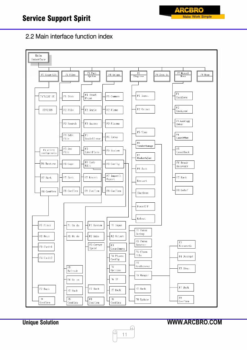
In the main interface, press 【F1】-【F8】to correspond to the following functions:
【F1】Graph management: there are dozens of graphic libraries of common parts, most of
which have both chip size and hole size.
【F2】Document management: enter optional hard disk files, USB flash drive files, find, edit,
delete, file import and export, preview graphics and otherwise operate.
【F3】Parts management: mirror image, rotation, plate correction, alignment, line selection,
code editing, etc. for processing parts.
【F4】Parameter settings: all parameters can be set here.
【F5】System diagnosis: input and output diagnosis, date and time settings and factory
management.
【F6】Enlarge the graph: enlarge the cutting graph.
【 F7】Manual movement: manually move the machine, in this interface, power-off,
breakpoint recovery operation, and laser torch bias operation can be done.
【F8】Zeroing: after the machine starts cutting money or cutting is completed, the
coordinates can be cleared.
【X】: Set cutting speed.
【Y】: Set manual shift speed.
【F】: Set the manual shift mode, which can be set to jog, linkage and fixed length. 【G】:
Set the moving distance when moving at a fixed length. Description: press G
to modify the fixed length distance number, and the manual transfer mode automatically
switches to the fixed length mode.
【Z】: The slit size can be set before the cutting operation starts or after the cutting is
completed.
【M】: Set the cutting mode. There are three modes: demo mode, oxygen gas cutting and
plasma cutting.
【START】: Start cutting.
【STOP】: Stop cutting.
【Space】: Enter the cutting interface.
Service Support Spirit
Unique Solution WWW.ARCBRO.COM
11
2.2 Main interface function index

Service Support Spirit
Unique Solution WWW.ARCBRO.COM
12
Chapter 3 Cutting Function
As shown in Pic 3.1, press the Space button on the main interface to enter the cutting
interface, as shown in Pic 3.2 below:
Pic 3.1 F7600 Series Main Interface
Pic 3.2 Cutting Main Interface
Service Support Spirit
Unique Solution WWW.ARCBRO.COM
13
displays the actual cutting path of the currently machined workpiece, including the
kerf value.
displays the status of the strong key, and the corresponding output port can be
opened and closed by the touch screen operation. Note: The strong current button of
the F7600 is at the operator panel on the right.
displays the status of the input and output ports used in the current cutting mode,
and the real-time IO timing output.
displays the current real-time machining speed, operating status, and machining
files. During the machining process, fast speed control can be achieved by pressing
[1]-[9]. For example, press the number [3], and the speed is automatically adjusted
to 30%; press the number [8], and the speed is automatically adjusted to 80%. At the
same time, [F4] or [END] can be used to decelerate, [F5] and [HOME] to accelerate.
displays the current cutting speed, and some parameters used for cutting, as well
as some cutting statistics information. The letters in [] above are shortcut keys, so
pressing them can quickly change the corresponding parameters.
displays the absolute coordinate position of the workpiece where the torch is
currently located.
displays currently executing G code. This status bar is a transparent form, which
can be folded or expanded by the arrow on the right.
[X] Modify the current cutting speed.
[Y] Modify the current manual shift speed.
[F] Change the current manual shift mode.
[G] Modify the fixed length of the current fixed length movement.
[Z] Press [Z] to set the kerf value before starting cutting or after cutting.
[START] Start cutting.
[STOP] Stop. Pressing it to pause all the actions that are going on in the system.
[F1] Back: The torch returns along the original path of the track (the I/O port is closed
at this time), and the piercing point will be suspended when it is back.
Service Support Spirit
Unique Solution WWW.ARCBRO.COM
14
[F2] Advance: The torch advances along the cutting path (the I/O port is closed).
[F3] walking frame or [F3] resetting: before just transferred into the processing file,
and the machine movement, here is the walking frame function, the machine will walk
the torch along the outer contour of the workpiece. After the machine is moved, here
is the resetting function and the machine will return to the zero coordinate of the
workpiece.
[F4] Deceleration: reduce the cutting speed by 3% per press. Reduce manual shift
speed when moving manually.
[F5] Acceleration: increase the cutting speed by 3% per press. Increase manual shift
speed when moving manually.
[F6] Preheating decrease: reduce the preheating time, skip the remaining preheat
time, and the system automatically remembers the preheat time.
[F7] Preheating increase: increase the preheating time by 15 seconds each time.
[F8] Select punching pointing: when the system is paused, the puncturing point is
selected, and after the startup is started, it is dynamical enlargement function.
Up, down, left and right 4 direction keys: move the cutting torch manually.
Service Support Spirit
Unique Solution WWW.ARCBRO.COM
15
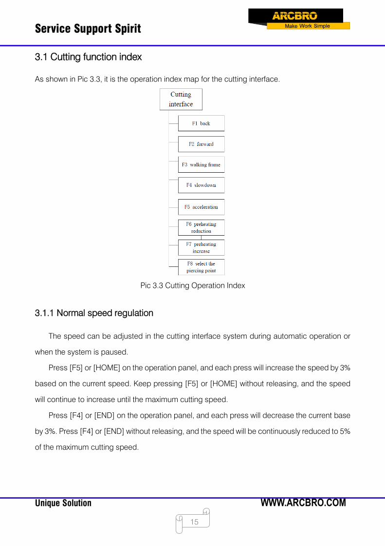
3.1 Cutting function index
As shown in Pic 3.3, it is the operation index map for the cutting interface.
Pic 3.3 Cutting Operation Index
3.1.1 Normal speed regulation
The speed can be adjusted in the cutting interface system during automatic operation or
when the system is paused.
Press [F5] or [HOME] on the operation panel, and each press will increase the speed by 3%
based on the current speed. Keep pressing [F5] or [HOME] without releasing, and the speed
will continue to increase until the maximum cutting speed.
Press [F4] or [END] on the operation panel, and each press will decrease the current base
by 3%. Press [F4] or [END] without releasing, and the speed will be continuously reduced to 5%
of the maximum cutting speed.
Service Support Spirit
Unique Solution WWW.ARCBRO.COM
16
3.1.2 Rapid speed regulation
Rapid speed regulation can be performed on the cutting interface during automatic
operation or when the system is paused.
In the cutting interface, press the number keys [1]-[9] on the operation panel, and the speed
will be quickly adjusted to 10 times the corresponding number. For example, press the number
[3], the speed will be automatically adjusted to 30% ; press the number [8], the speed will be
automatically adjusted to 80%.
3.2 Advance
The cutting is paused or ended. Press the [F2] key in the cutting interface, the system starts
to go empty. There is no IO switching process such as ignition, perforation, etc., and the torch
is moved along the contour of the cutting pattern. Press the [F2] or [STOP] key again to stop
the system.
This function can also be used before cutting, if you want to check whether the cutting path
is correct or the code is correct or not, or you need to pass the torch during processing.
The forward speed and the cutting speed are set separately, and the "forward and reverse
speed" in the commonly used parameters is used to set it.
3.3 Back
In the process of processing, if the original track needs to be returned due to reasons such
as uncut, etc., the following process can be performed:
Press the [STOP] key first to put the cutter in the pause state.
Press the [F1] key in the cutting interface, the cutting machine will return along the original
track. When the torch retreats to the position to be retracted, press the [F1] or [STOP] key again.
If the retraction is too much, press [F2] at this time, and it can move forward in empty and then
proceed to the desired position.
Caution: The forward and reverse functions can be repeated until the torch is in the desired
position.
Service Support Spirit
Unique Solution WWW.ARCBRO.COM
17
When the torch is in the desired position, press the [START] key again. If the current cutting
code line is G01 or G02 or G03, the system will automatically perforate before executing these
programs, and then continue to run the current program; if the current line is not G01 or G02 or
G03, the system directly executes the current line program.
3.4 Offset cutting / cutting back / just back
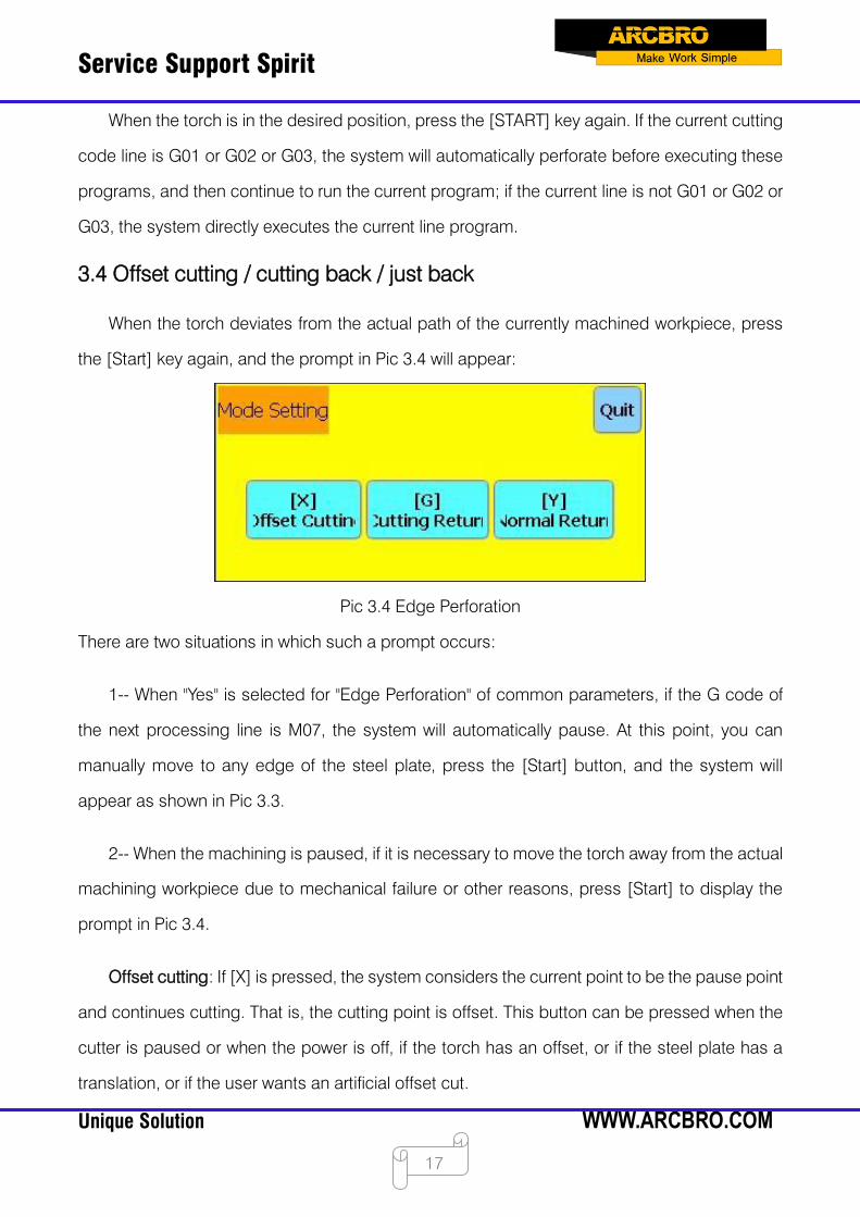
When the torch deviates from the actual path of the currently machined workpiece, press
the [Start] key again, and the prompt in Pic 3.4 will appear:
Pic 3.4 Edge Perforation
There are two situations in which such a prompt occurs:
1-- When "Yes" is selected for "Edge Perforation" of common parameters, if the G code of
the next processing line is M07, the system will automatically pause. At this point, you can
manually move to any edge of the steel plate, press the [Start] button, and the system will
appear as shown in Pic 3.3.
2-- When the machining is paused, if it is necessary to move the torch away from the actual
machining workpiece due to mechanical failure or other reasons, press [Start] to display the
prompt in Pic 3.4.
Offset cutting: If [X] is pressed, the system considers the current point to be the pause point
and continues cutting. That is, the cutting point is offset. This button can be pressed when the
cutter is paused or when the power is off, if the torch has an offset, or if the steel plate has a
translation, or if the user wants an artificial offset cut.

Service Support Spirit
Unique Solution WWW.ARCBRO.COM
18
Cutting back: If [G] is pressed, the system first cuts back to the pause point, and then
continues cutting according to the original graphic. This function is especially useful for thicker
steel plates, which can reduce the preheating time and improve the cutting efficiency; this
function is commonly used edge perforation function.
Just back: If [Y] is pressed, the system will only return to the pause point quickly and then
pause. When the cutting process is found to be faulty, or other problems, the torch needs to be
removed from the cutting area for inspection. When the inspection needs to be returned to the
pause point, the button can be pressed. After returning to the pause point, press the [Start] key
again, and the system will automatically start cutting according to the original graphic.
3.5 Resetting function
When the machining is paused, if [F3] is pressed at this time, the system will automatically
return to the starting point of the machining workpiece. After returning to the original point, the
system will exit the cutting state.
Pic 3.5 Cutting Main Interface

Service Support Spirit
Unique Solution WWW.ARCBRO.COM
19
In the process of returning to the reference, the user can also press the [Stop] key to stop
the operation. After stopping, continue to press [F3] to perform the return operation, or press
the [Start] key to restart the cutting. The return and stop are not limited by the number of times.
3.6 Oxygen gas preheating time adjustment
During the preheating process, press [START] or [F9] to skip the preheating and piercing
delay process and immediately open the punching signal to start cutting.
During the preheating process, press [Stop] (i.e. [F10] key) to maintain the preheating state
until the [F9] key is pressed again, and the system continues the cutting process.
During the preheating process, press the [F6] key to end the preheating state, and
remember this preheating time. This preheating time is used to preheat before encountering the
M02 or M30 code.
Example: For example, the preheating time set by the original system is 60 seconds. When
preheating is required, there will be a countdown on the interface. When the reading is normal,
the system starts to continue cutting, but if there is still 10 seconds remaining in the system
countdown, press F6, and the system immediately stops preheating, starts the cutting operation,
and records the time that the preheating has been 50 seconds. The system automatically
assumes that the user needs the preheating time of 50 seconds, and the preheating time during
the next preheating will become 50 seconds.
During the preheating process, each time the F7 key is pressed, and the preheating time is
increased by 15 seconds, and later preheating time is maintained after the increase, until the
cutting is completed.
Example: The preheating time set by the original system is 60 seconds. During the system
countdown, press F7 once, the countdown on the interface is added for 15 seconds, and the
next preheating time becomes 75 seconds when the next preheating is required.

Service Support Spirit
Unique Solution WWW.ARCBRO.COM
20
3.7 Select the piercing point
Before the cutting is started or when the cutting is paused, [F8] function key is to "Select
Piercing Point". At this time, press F8, and the system will prompt:
Pic 3.6 Selecting the Piercing Point
Pic 3.1 If the ESC is pressed, the system will return to the cutting interface. If F2 is selected,
the system prompt to select the corresponding line number:
Pic 3.7 Line Number Selection

Service Support Spirit
Unique Solution WWW.ARCBRO.COM
21
At this point, you can manually enter the line number, click [F8] to confirm, and the system
will start cutting from the selected code line.
If F1 is selected, the system prompt to select the corresponding hole number:
Pic 3.8 Hole Number Selection
At this point, you can manually enter the hole number, click [F8] to confirm, the system will
start cutting from the selected perforation point.
3.8 Dynamic zoom
After the machining starts, the [F8] of the cutting interface will change to "Zoom". At this
time, press the F8 button, the machining graphic will be enlarged in the drawing area and can
be dynamically tracked.
Pic 3.9 Cutting Interface Function Keys during Dynamic Zooming
Press the F8 button continuously, and the system will enlarge the graph step by step.
Press the ESC key to exit the enlarged display and return to the normal cutting interface.

Service Support Spirit
Unique Solution WWW.ARCBRO.COM
22
3.9 Exit cutting
When the cutting is not completed and the cutting machine is in the pause state, if the [Esc]
key is pressed in the cutting interface, the system will prompt whether to exit the cutting. If [F8]
is pressed, the cutting will be exited; if the [Esc] button is pressed, the cutting will not be exited,
and the cutting will continue at the original position after entering the cutting interface again.
Pic 3.10 Exit Cutting Prompt
3.10 Walking frame
Pic 3.11 Walking Frame
Pic 3.1 Before starting the machining, press the space bar [Space] to enter the automatic
machining interface. At this time, [F3] is the border function. After F3 is pressed, the system will
walk counterclockwise along the blue frame shown in Pic 3.11. The starting point is in the lower
left corner. After walking, the system prompts.
Service Support Spirit
Unique Solution WWW.ARCBRO.COM
23
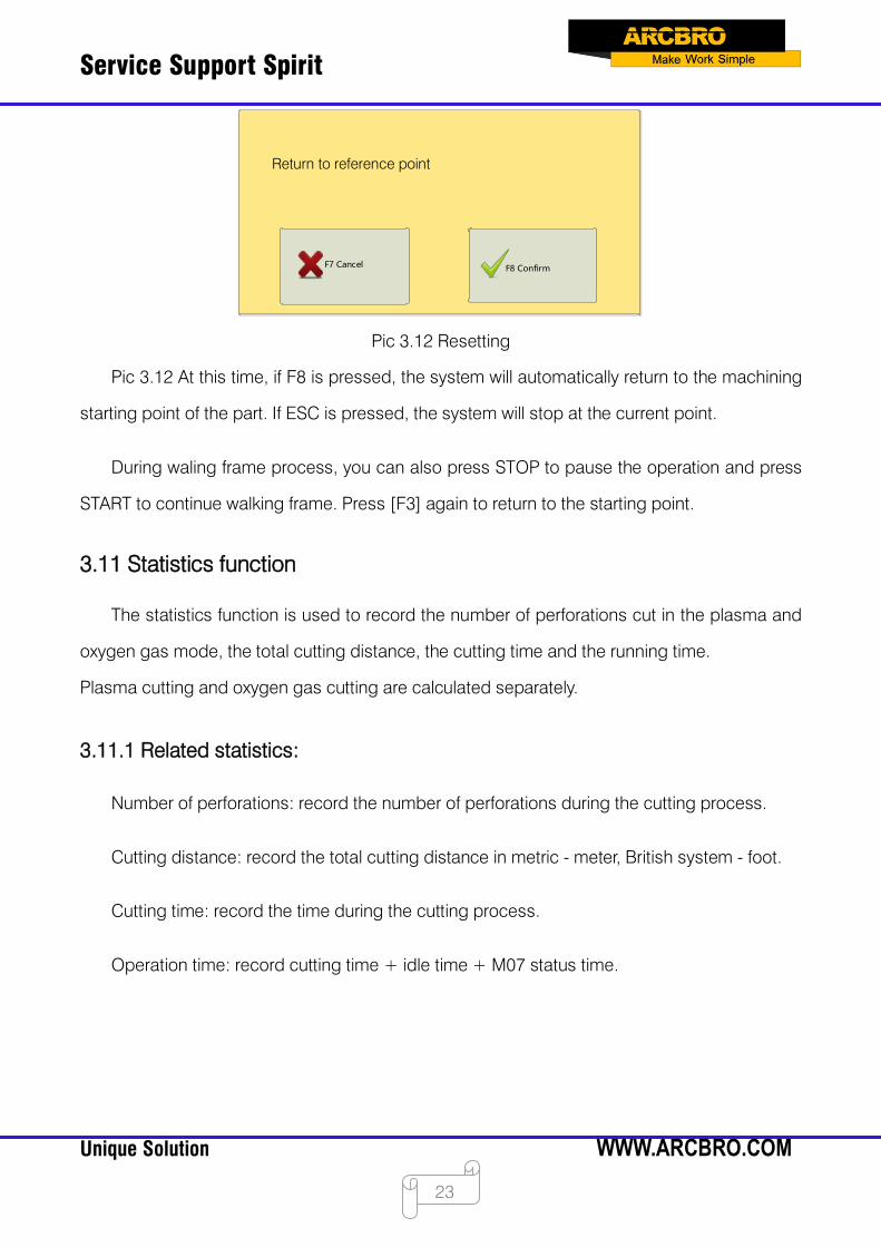
Pic 3.12 Resetting
Pic 3.12 At this time, if F8 is pressed, the system will automatically return to the machining
starting point of the part. If ESC is pressed, the system will stop at the current point.
During waling frame process, you can also press STOP to pause the operation and press
START to continue walking frame. Press [F3] again to return to the starting point.
3.11 Statistics function
The statistics function is used to record the number of perforations cut in the plasma and
oxygen gas mode, the total cutting distance, the cutting time and the running time.
Plasma cutting and oxygen gas cutting are calculated separately.
3.11.1 Related statistics:
Number of perforations: record the number of perforations during the cutting process.
Cutting distance: record the total cutting distance in metric - meter, British system - foot.
Cutting time: record the time during the cutting process.
Operation time: record cutting time + idle time + M07 status time.
Return to reference point

Service Support Spirit
Unique Solution WWW.ARCBRO.COM
24
3.11.2 Statistics display
Under the oxygen gas cutting interface, the number of piercing times and cutting distance
(unit: metric - meter, British system - foot), cutting time and running time of oxygen gas cutting
are displayed in real time in the lower right corner. As shown in Pic 3.13:
Pic 3.13 Oxygen Gas Cutting Interface
Under the plasma cutting interface, the number of piercing times and cutting distance (unit:
metric - meter, British system - foot), cutting time and running time of plasma cutting are
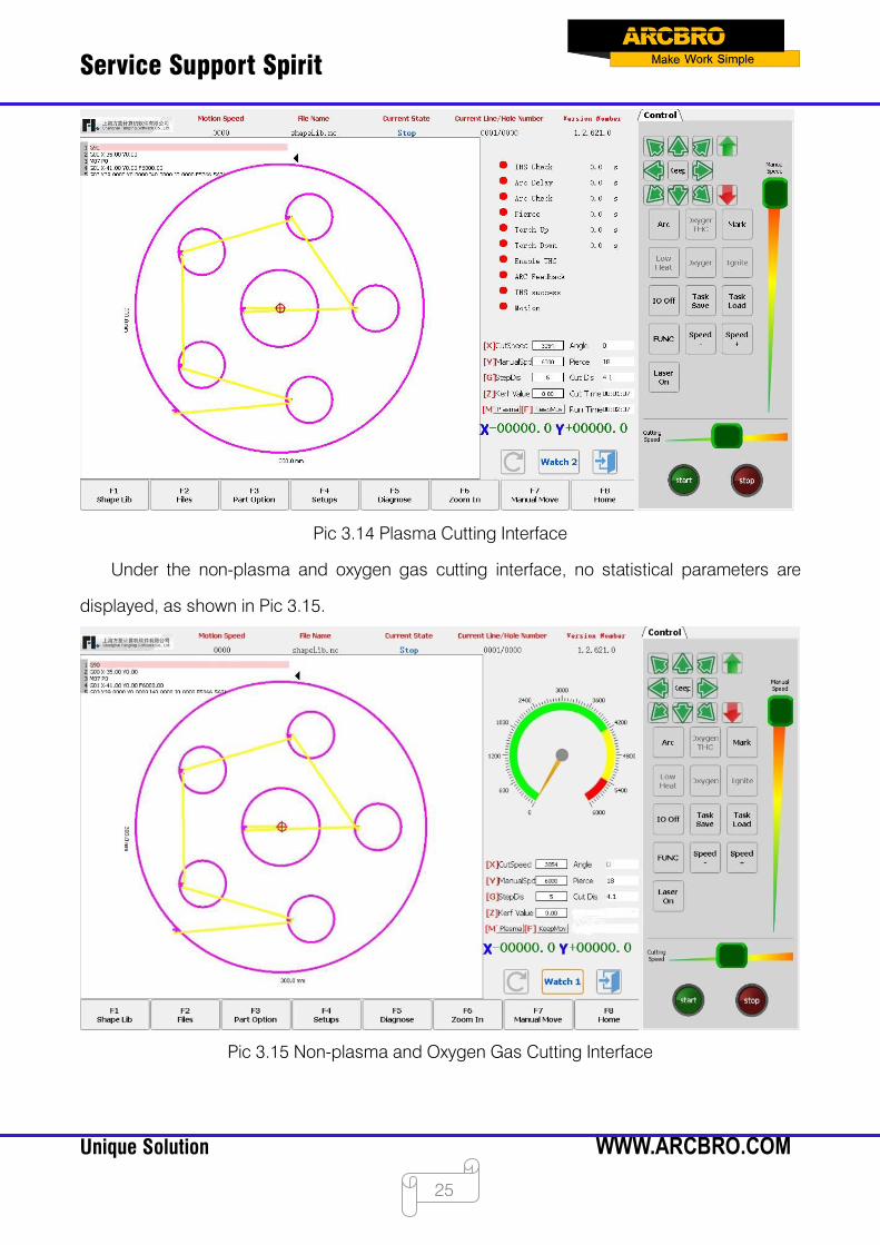
displayed in real time in the lower right corner. As shown in Pic 3.14:
Service Support Spirit
Unique Solution WWW.ARCBRO.COM
25
Pic 3.14 Plasma Cutting Interface
Under the non-plasma and oxygen gas cutting interface, no statistical parameters are
displayed, as shown in Pic 3.15.
Pic 3.15 Non-plasma and Oxygen Gas Cutting Interface

Service Support Spirit
Unique Solution WWW.ARCBRO.COM
26
Chapter 4 Component Options
Before starting to cut, press [F3 Part Options] on the main interface to select the starting
point, angle correction, repeating, scaling, mirroring, rotation, etc. The interface is shown in Pic
4.1 Component Options.
Pic 4.1 Part Options
Press X to mirror the horizontal axis (X axis), that is, up and down mirror.
Press Y to mirror the vertical axis (Y axis), that is, left and right mirror.
4.1 Starting point selection
After pressing F1, the system prompts to select the starting point:
Pic 4.2 Starting Point Selection
Service Support Spirit
Unique Solution WWW.ARCBRO.COM
27
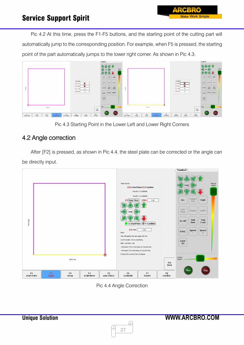
Pic 4.2 At this time, press the F1-F5 buttons, and the starting point of the cutting part will
automatically jump to the corresponding position. For example, when F5 is pressed, the starting
point of the part automatically jumps to the lower right corner. As shown in Pic 4.3.
Pic 4.3 Starting Point in the Lower Left and Lower Right Corners
4.2 Angle correction
After [F2] is pressed, as shown in Pic 4.4, the steel plate can be corrected or the angle can
be directly input.
Pic 4.4 Angle Correction
Service Support Spirit
Unique Solution WWW.ARCBRO.COM
28
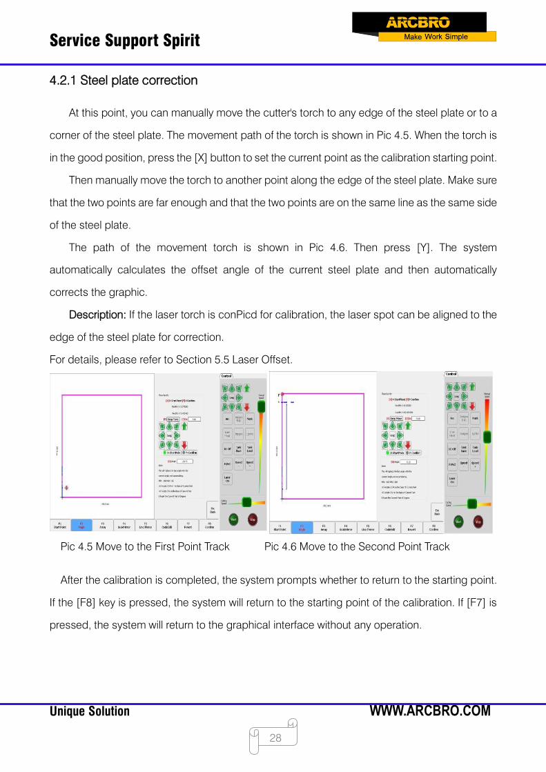
4.2.1 Steel plate correction
At this point, you can manually move the cutter's torch to any edge of the steel plate or to a
corner of the steel plate. The movement path of the torch is shown in Pic 4.5. When the torch is
in the good position, press the [X] button to set the current point as the calibration starting point.
Then manually move the torch to another point along the edge of the steel plate. Make sure
that the two points are far enough and that the two points are on the same line as the same side
of the steel plate.
The path of the movement torch is shown in Pic 4.6. Then press [Y]. The system
automatically calculates the offset angle of the current steel plate and then automatically
corrects the graphic.
Description: If the laser torch is conPicd for calibration, the laser spot can be aligned to the
edge of the steel plate for correction.
For details, please refer to Section 5.5 Laser Offset.
Pic 4.5 Move to the First Point Track Pic 4.6 Move to the Second Point Track
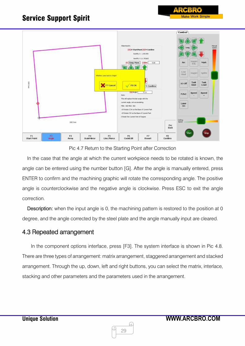
After the calibration is completed, the system prompts whether to return to the starting point.
If the [F8] key is pressed, the system will return to the starting point of the calibration. If [F7] is
pressed, the system will return to the graphical interface without any operation.
Service Support Spirit
Unique Solution WWW.ARCBRO.COM
29
Pic 4.7 Return to the Starting Point after Correction
In the case that the angle at which the current workpiece needs to be rotated is known, the
angle can be entered using the number button [G]. After the angle is manually entered, press
ENTER to confirm and the machining graphic will rotate the corresponding angle. The positive
angle is counterclockwise and the negative angle is clockwise. Press ESC to exit the angle
correction.
Description: when the input angle is 0, the machining pattern is restored to the position at 0
degree, and the angle corrected by the steel plate and the angle manually input are cleared.
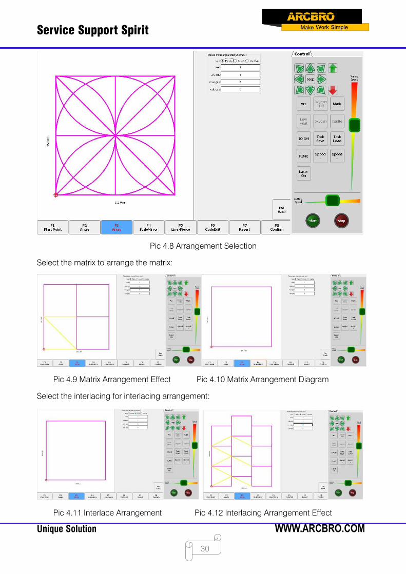
4.3 Repeated arrangement
In the component options interface, press [F3]. The system interface is shown in Pic 4.8.
There are three types of arrangement: matrix arrangement, staggered arrangement and stacked
arrangement. Through the up, down, left and right buttons, you can select the matrix, interlace,
stacking and other parameters and the parameters used in the arrangement.
Service Support Spirit
Unique Solution WWW.ARCBRO.COM
30
Pic 4.8 Arrangement Selection
Select the matrix to arrange the matrix:
Pic 4.9 Matrix Arrangement Effect Pic 4.10 Matrix Arrangement Diagram
Select the interlacing for interlacing arrangement:
Pic 4.11 Interlace Arrangement Pic 4.12 Interlacing Arrangement Effect

Service Support Spirit
Unique Solution WWW.ARCBRO.COM
31
Select the stacking for stacking arrangement:
Pic 4.13 Stacking Arrangement Pic 4.14 Stacking Arrangement Effect
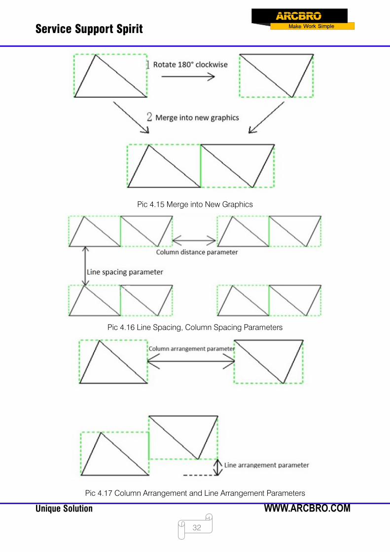
The stacking arrangement is mainly applied to graphics with symmetrical arrangement,
such as triangles, trapezoids, and the like. The stacking arrangement first rotates the
current graphic 180°clockwise from the center, and then the original graphic and the
mirrored graphic are arranged in pairs to form a new graphic. The combination process is
shown in Pic 4.16. Then, the combined new graphics are arranged in a matrix. Parameter
Description:
Number of rows: The number of rows to be arranged for the combined graphics.
Number of columns: The number of columns to be arranged for the combined graphics.
Line spacing: The distance between the combined graphics and the combined graphics
in the Y direction. This parameter can be negative.
Row pitch: The spacing between the combined graphics and the combined graphics in
the X direction. This parameter can be negative.
Line arrangement: The distance between the two graphics in the Y direction when they are
combined into a new graphic. This parameter can be negative.
Column arrangement: When two graphics are combined into a new graphic, the distance
between the two graphics in the X direction. This parameter can be negative.
Service Support Spirit
Unique Solution WWW.ARCBRO.COM
32
Pic 4.15 Merge into New Graphics
Pic 4.16 Line Spacing, Column Spacing Parameters
Pic 4.17 Column Arrangement and Line Arrangement Parameters
Service Support Spirit
Unique Solution WWW.ARCBRO.COM
33
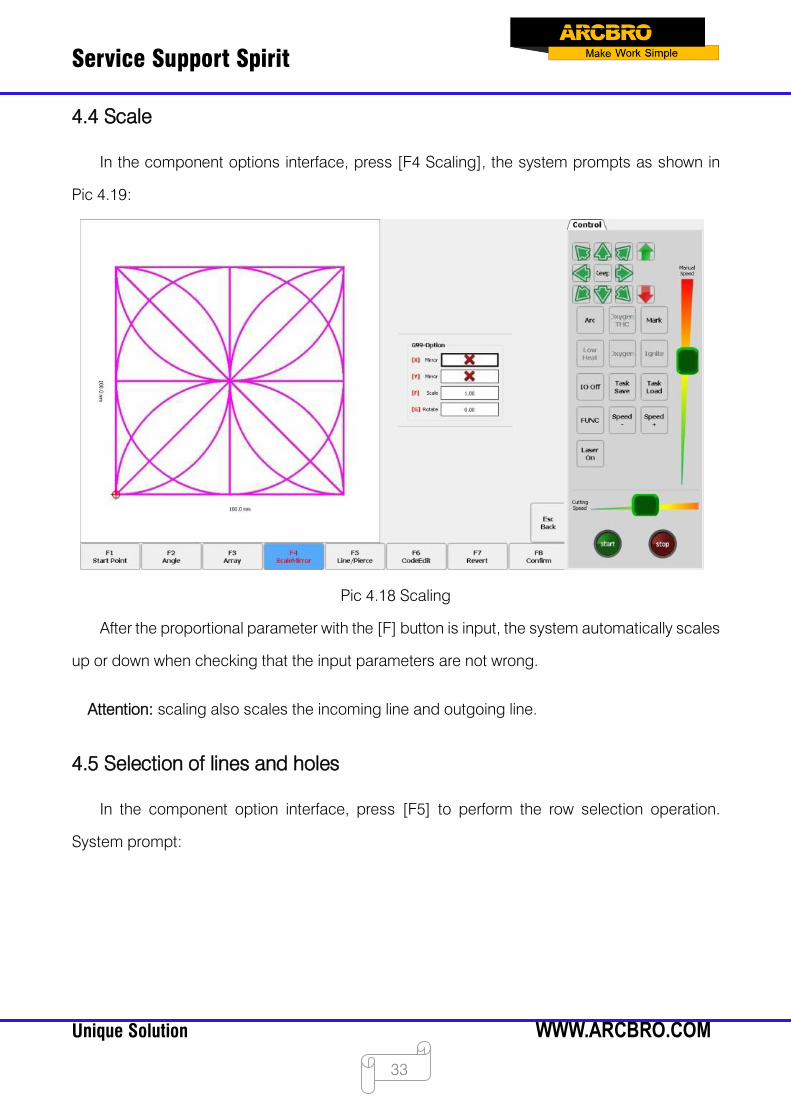
4.4 Scale
In the component options interface, press [F4 Scaling], the system prompts as shown in
Pic 4.19:
Pic 4.18 Scaling
After the proportional parameter with the [F] button is input, the system automatically scales
up or down when checking that the input parameters are not wrong.
Attention: scaling also scales the incoming line and outgoing line.
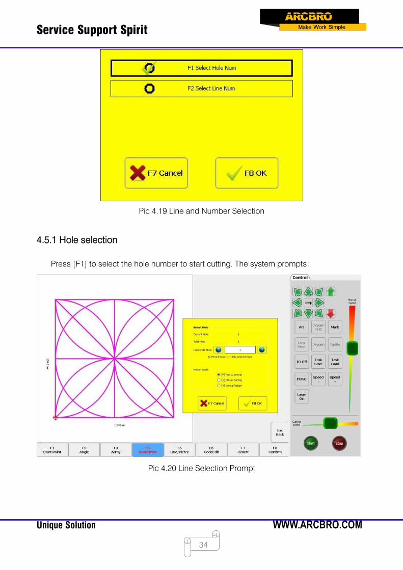
4.5 Selection of lines and holes
In the component option interface, press [F5] to perform the row selection operation.
System prompt:
Service Support Spirit
Unique Solution WWW.ARCBRO.COM
34
Pic 4.19 Line and Number Selection
4.5.1 Hole selection
Press [F1] to select the hole number to start cutting. The system prompts:
Pic 4.20 Line Selection Prompt
Service Support Spirit
Unique Solution WWW.ARCBRO.COM
35
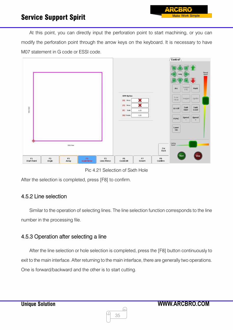
At this point, you can directly input the perforation point to start machining, or you can
modify the perforation point through the arrow keys on the keyboard. It is necessary to have
M07 statement in G code or ESSI code.
Pic 4.21 Selection of Sixth Hole
After the selection is completed, press [F8] to confirm.
4.5.2 Line selection
Similar to the operation of selecting lines. The line selection function corresponds to the line
number in the processing file.
4.5.3 Operation after selecting a line
After the line selection or hole selection is completed, press the [F8] button continuously to
exit to the main interface. After returning to the main interface, there are generally two operations.
One is forward/backward and the other is to start cutting.
Service Support Spirit
Unique Solution WWW.ARCBRO.COM
36
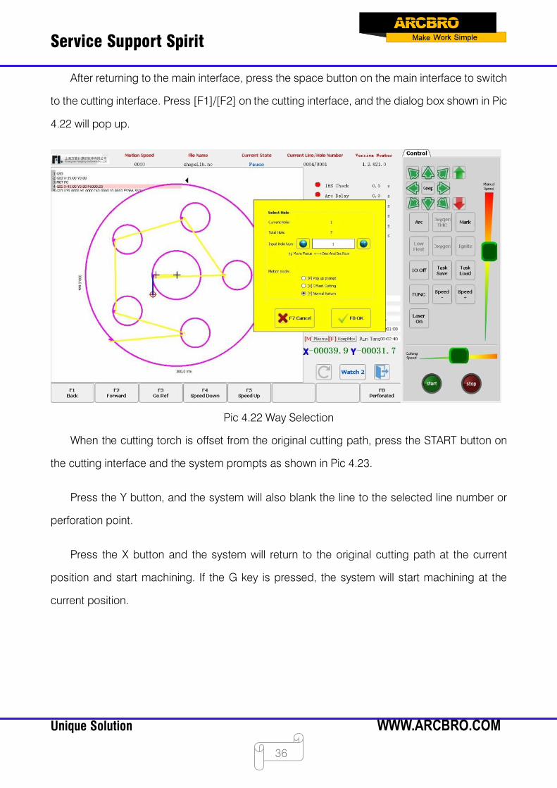
After returning to the main interface, press the space button on the main interface to switch
to the cutting interface. Press [F1]/[F2] on the cutting interface, and the dialog box shown in Pic
4.22 will pop up.
Pic 4.22 Way Selection
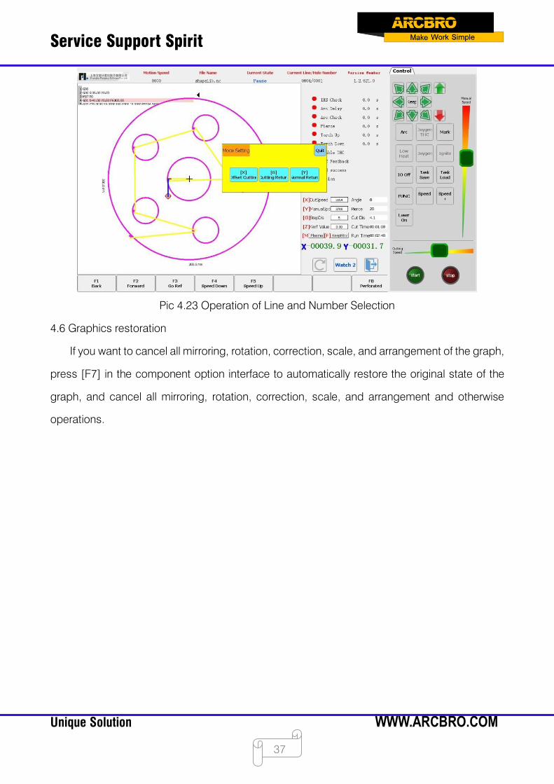
When the cutting torch is offset from the original cutting path, press the START button on
the cutting interface and the system prompts as shown in Pic 4.23.
Press the Y button, and the system will also blank the line to the selected line number or
perforation point.
Press the X button and the system will return to the original cutting path at the current
position and start machining. If the G key is pressed, the system will start machining at the
current position.
Service Support Spirit
Unique Solution WWW.ARCBRO.COM
37
Pic 4.23 Operation of Line and Number Selection
4.6 Graphics restoration
If you want to cancel all mirroring, rotation, correction, scale, and arrangement of the graph,
press [F7] in the component option interface to automatically restore the original state of the
graph, and cancel all mirroring, rotation, correction, scale, and arrangement and otherwise
operations.

Service Support Spirit
Unique Solution WWW.ARCBRO.COM
38
Chapter 5 Manual Functions
Click [F7 Manual Motion] on the main interface of the system to display the panel for manual
shifting. As shown in Pic 5.1, the manual shift mode can be switched by the [F] button, which is
divided into: jog, linkage and fixed length.
Manual shifting of the machine in four directions can be achieved by the up, down, left and
right buttons.
Pic 5.1 Manual Main Interface
The speed in the manual state is controlled by the manual shift speed parameter in the
usual parameters.
When moving manually, you can press HOME to accelerate, END to decelerate, or press
the number key in the manual interface, the system speed will automatically adjust to the
percentage of the corresponding number 10 times speed.
For example, press the number [3], the speed will be automatically adjusted to 30%; press
the number [8], the speed will be automatically adjusted to 80%.
Service Support Spirit
Unique Solution WWW.ARCBRO.COM
39
5.1 Jog
In the main interface, use the [F] button to switch the manual shift mode. In the jog mode,
press any direction button, and the system will move in that direction; release the direction
button, and the system stops moving.
5.2 Linkage
In the main interface, use the [F] key to switch the manual shift mode. In the linkage mode,
press any direction button and release, and the system will move in that direction; press any
direction button or [Stop] button again and the system stops moving.
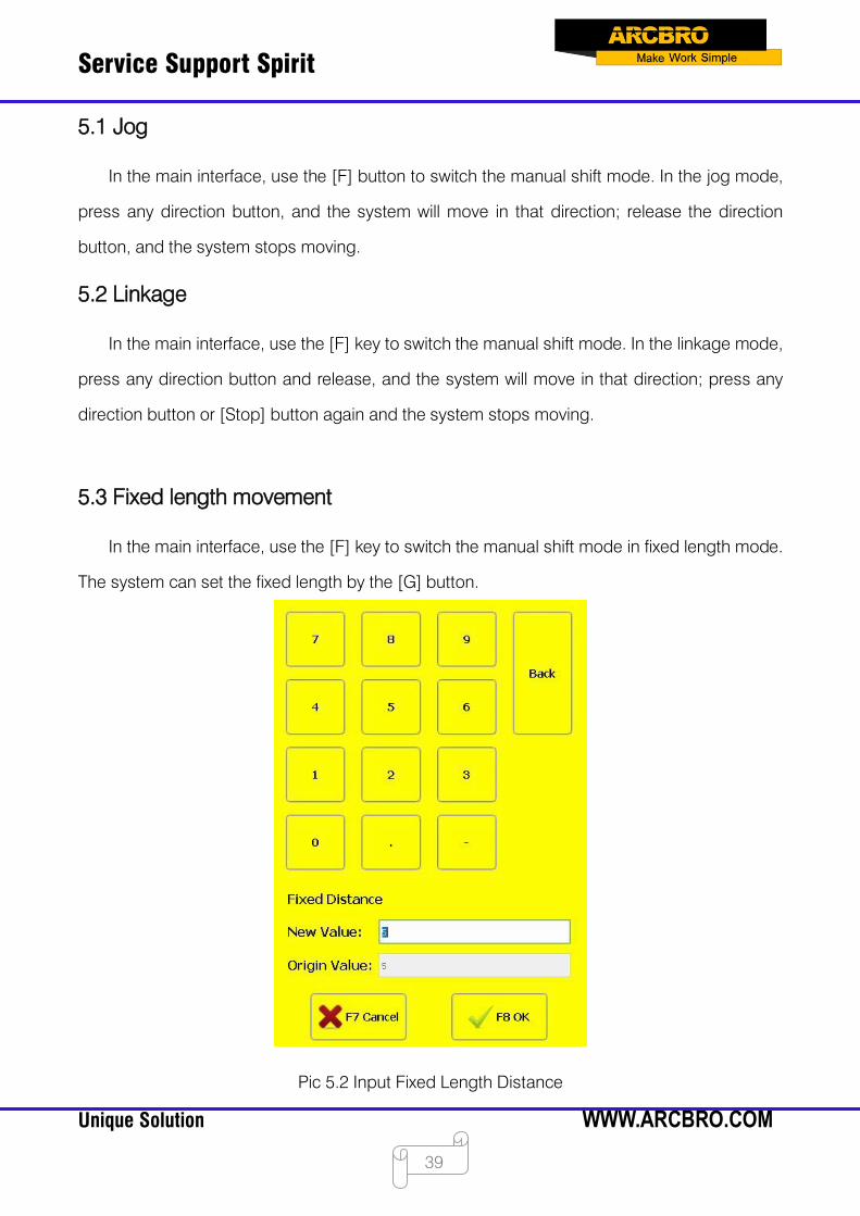
5.3 Fixed length movement
In the main interface, use the [F] key to switch the manual shift mode in fixed length mode.
The system can set the fixed length by the [G] button.
Pic 5.2 Input Fixed Length Distance
Service Support Spirit
Unique Solution WWW.ARCBRO.COM
40
After entering the fixed length, press [F8] to confirm. At this time, press any direction button
and release, the system will automatically stop after moving the fixed distance in that direction;
press any direction button or [stop] button during the movement, and the system will stop
moving.
5.4 Break restoration
The break restoration function is mainly used to cause power failure during the cutting
process and to temporarily stop cutting to handle other things. In order to ensure the normal
use of the break restoration function, the following conditions must be met:
When the system is in the pause state, the system automatically remembers the current
pause point as a breakpoint.
When the system is in the cutting operation, in the case of power failure, the system will
remember the position when the power is off as a breakpoint.
When it is necessary to continue machining from the breakpoint, after the system is powered
on, do not move the torch position. Press [F7] on the main interface to enter the manual shifting
interface, as shown in Pic 5.3, and then press [F6] to restore the breakpoint. After restoration, if
the torch has not been moved, it is just in the position before the power is cut off. At this time,
press the [START] button, the system will start processing directly from the breakpoint.
Service Support Spirit
Unique Solution WWW.ARCBRO.COM
41
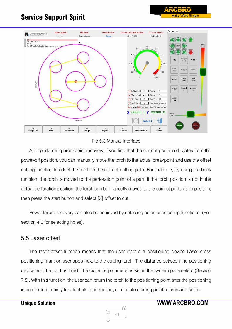
Pic 5.3 Manual Interface
After performing breakpoint recovery, if you find that the current position deviates from the
power-off position, you can manually move the torch to the actual breakpoint and use the offset
cutting function to offset the torch to the correct cutting path. For example, by using the back
function, the torch is moved to the perforation point of a part. If the torch position is not in the
actual perforation position, the torch can be manually moved to the correct perforation position,
then press the start button and select [X] offset to cut.
Power failure recovery can also be achieved by selecting holes or selecting functions. (See
section 4.6 for selecting holes).
5.5 Laser offset
The laser offset function means that the user installs a positioning device (laser cross
positioning mark or laser spot) next to the cutting torch. The distance between the positioning
device and the torch is fixed. The distance parameter is set in the system parameters (Section
7.5). With this function, the user can return the torch to the positioning point after the positioning
is completed, mainly for steel plate correction, steel plate starting point search and so on.
Service Support Spirit
Unique Solution WWW.ARCBRO.COM
42
[F4] Laser offset: You can move the crosshairs to the position of the original torch..
[F5] Laser return: enable to move the torch to the crosshair position.
5.6 Double-trolley
5.6.1 Double-trolley configuration interface
After enabling the double trolley in the X-axis parameter configuration in [F4 Parameter
Setting]-[F5 System]-[F2 Axis Parameter], the double-trolley function can be used after the
program is restarted. (Note: The axis card must be restarted after the double car function is
enabled to use normally, you can enter the double-trolley manual interface by [F7 Manual]-[F3
double-trolley], as shown below:
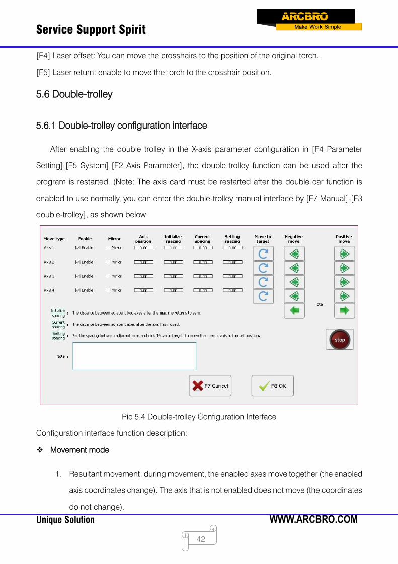
Pic 5.4 Double-trolley Configuration Interface
Configuration interface function description:
Movement mode
1. Resultant movement: during movement, the enabled axes move together (the enabled
axis coordinates change). The axis that is not enabled does not move (the coordinates
do not change).
Service Support Spirit
Unique Solution WWW.ARCBRO.COM
43
2. Uniaxial movement: the current axis can be moved left and right.
Enable
For a single axis, enable or disable. The enabled axis can be moved. There are a total of N
axes. The 2-X axis must be enabled. (X >= 2 , X < = N)
Axis coordinate
The coordinate position of the current axis in the machine coordinate system.
Initial spacing
When the current interval is 0, the time to complete the zero return is performed. The spacing
of the axis from the previous axis.
Current spacing
1. Display as (none) when not set.
2. This value is invalid when there is no return to zero although it is set. (display as: not
returned to zero).
3. If the value is modified, the axis moves to that position immediately. (This function does
not work when there is no zero return).
4. The zero offset is determined. Zero offset = Spacing - Spacing after zeroing.
Description:
5. If the axis 2 is moved separately, the distance from axis 2 to axis 1 will change in real
time (coordinate offset of axis 2 - coordinate offset of axis 1), and the distance of axis 3
from axis 2 will also change in real time (coordinate offset of axis 3 - coordinate offset
of axis 2).
Set spacing
Set the spacing of the current axis to use for the Move In Place button.

Service Support Spirit
Unique Solution WWW.ARCBRO.COM
44
Moving in the negative direction
1. Uniaxial movement: the current axis is moved and the other axes do not move. (At this
point, the "Axis Enable" configuration is invalid)
2. Resultant movement: The enabled axes move together. The axis that is not enabled
does not move.
Moving in the positive direction
Others are the same as "forward movement".
Return to zero
It is convenient for the user to measure the shaft spacing after zero return.
1. Zeroing direction: According to the parameter selection, zero return is supported.
2. Axis 1-axis N has 2 limit switches.
3. Return to zero order:
Positive zero return:
1. Axis 1 first returns to zero, then axis 2, and finally axis N.
2. The axis N moves to the user set pitch and finally the axis 1 moves to the user pitch.
Reverse zero return:
1. Axis N returns to zero first, and finally axis 1.
2. Axis 1 moves to the user set pitch and finally axis N moves to the user pitch.
3. During the zero return process, the other is checked in the hard limit. If the hard limit
occurs, the zero return is stopped.
4. The zero return process can be conPicd to primary zero return or secondary zero return.
Use the encoder to return to zero.
Service Support Spirit
Unique Solution WWW.ARCBRO.COM
45
5.6.2 Shaft wiring
When "Double-trolley Enable" is enabled, use "axis 1" and "axis 4" on the control card to
output terminals. The Z axis used in the “Drilling and Cutting Integrated Function” cannot be
used at this time.
5.7 Task saving and recovery
The following situations will be encountered in actual production: pause a graphic that is
being cut and add a graphic that is urgently needed. In this case, the task saving and recovery
function is used. The prerequisite for using the task saving function is: do not move the
suspended cut plate.
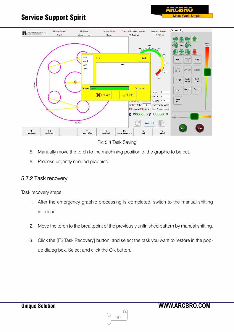
5.7.1 Task saving
The task saving operation steps are as follows:
1. Pause the cut graphic and exit the cutting state.
2. In the main interface, click [F7 Manual Movement] to switch to the manual shifting
interface.
3. Click the [F1 Task Saving] button on the manual transfer interface.
4. Enter the task name in the pop-up dialog box and click OK.
Service Support Spirit
Unique Solution WWW.ARCBRO.COM
46
Pic 5.4 Task Saving
5. Manually move the torch to the machining position of the graphic to be cut.
6. Process urgently needed graphics.
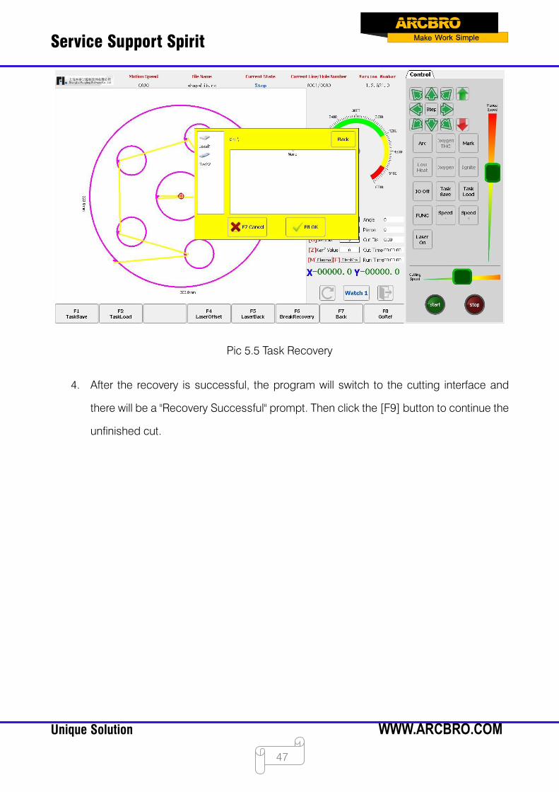
5.7.2 Task recovery
Task recovery steps:
1. After the emergency graphic processing is completed, switch to the manual shifting
interface.
2. Move the torch to the breakpoint of the previously unfinished pattern by manual shifting.
3. Click the [F2 Task Recovery] button, and select the task you want to restore in the pop-
up dialog box. Select and click the OK button.
Service Support Spirit
Unique Solution WWW.ARCBRO.COM
47
Pic 5.5 Task Recovery
4. After the recovery is successful, the program will switch to the cutting interface and
there will be a "Recovery Successful" prompt. Then click the [F9] button to continue the
unfinished cut.
Service Support Spirit
Unique Solution WWW.ARCBRO.COM
48
Chapter 6 Document Management
The cutting file formats supported by this system are txt, cnc, nc, B3, MPG, etc. The system
can not only edit existing files, but also export existing files to the outside or import external files
into the system.
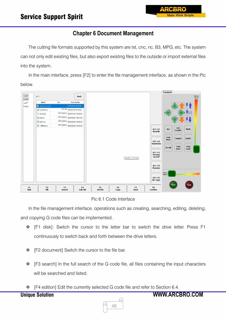
In the main interface, press [F2] to enter the file management interface, as shown in the Pic
below.
Pic 6.1 Code Interface
In the file management interface, operations such as creating, searching, editing, deleting,
and copying G code files can be implemented.
[F1 disk]: Switch the cursor to the letter bar to switch the drive letter. Press F1
continuously to switch back and forth between the drive letters.
[F2 document] Switch the cursor to the file bar.
[F3 search] In the full search of the G code file, all files containing the input characters
will be searched and listed.
[F4 edition] Edit the currently selected G code file and refer to Section 6.4.
Service Support Spirit
Unique Solution WWW.ARCBRO.COM
49
[F5 deletion] Delete the selected file or current folder.
[F6 copy] Copy the file to another folder or to a USB flash drive.
[F7 return]: return to the main interface.
[F8 confirmation] If the current cursor place is a G code file, the current processing file is
loaded into the system, and the system automatically returns to the main interface. If it is
a folder, the folder will be opened.
[SFT+F1]: Create a new G code file.
[SFT+F2]: Create a new file folder.
[SFT+F3] Turn the live preview function on or off, and the G code file where the cursor is
located is displayed graphically in the preview area.
[SFT+F4]: Rename the selected file.
[SFT+F5]: Add the identifiable G code file format suffix.
6.1 Disk
Click [F1 disk] to position the cursor to the drive letter column for the drive letter switch.
6.2 File
Click [F2 File] to position the cursor to the file bar and use the up and down buttons or [F2]
to select the file.
6.3 Find file
Press [F3] in the file management interface to search for files. Enter some or all of the
characters of the file name you are looking for. Press F8 and the system will list the results of
the search.

Service Support Spirit
Unique Solution WWW.ARCBRO.COM
50
Pic 6.2 Find Files
6.4 Code editing
In the file management interface, move the cursor to the file name you want to edit and
press [F4] to edit the code. The selected G code file can be edited as shown in Pic 6.3.
Pic 6.3 Code Edition
[F1] Cancellation: cancel the operation in the previous step.
[F2] Recreation: restore the cancelled operation.
[F3] Copy: select the code to be copied and the copy button is available.
Service Support Spirit
Unique Solution WWW.ARCBRO.COM
51
[F4] Paste: paste the copied code.
[F5] Refresh: refresh the current code.
[F6] Skip: skip to the code of the set line.
[F7] Return: Go back to the previous screen and do not save changes made.
[F8] Confirmation: save modifications and return to the previous screen.
[SFT+F1] Saving: save modifications.
[SFT+F2] Saving as: save the current G code file as another file.
[SFT+F3] Delete line: delete the line where the current cursor is.
[SFT+F5] select row: select the row where the current cursor is located.
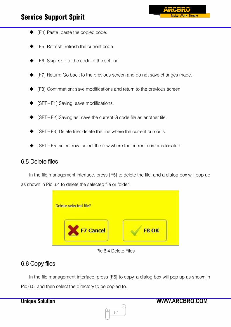
6.5 Delete files
In the file management interface, press [F5] to delete the file, and a dialog box will pop up
as shown in Pic 6.4 to delete the selected file or folder.
Pic 6.4 Delete Files
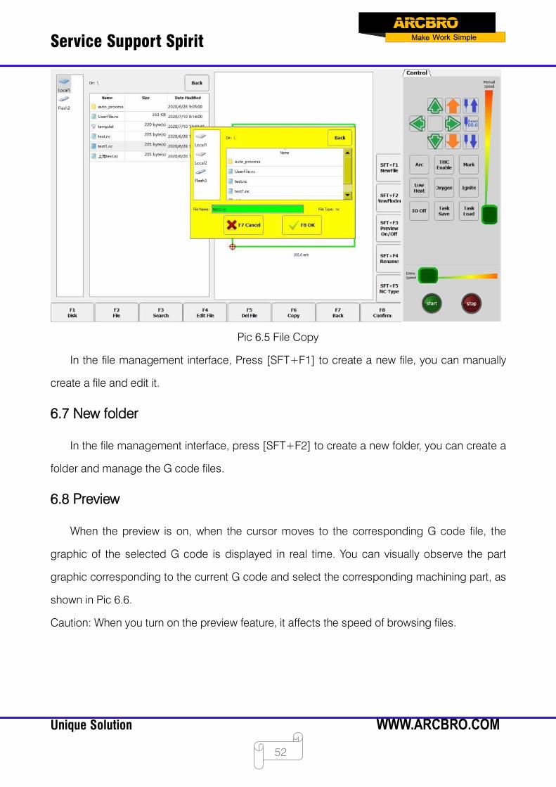
6.6 Copy files
In the file management interface, press [F6] to copy, a dialog box will pop up as shown in
Pic 6.5, and then select the directory to be copied to.
Service Support Spirit
Unique Solution WWW.ARCBRO.COM
52
Pic 6.5 File Copy
In the file management interface, Press [SFT+F1] to create a new file, you can manually
create a file and edit it.
6.7 New folder
In the file management interface, press [SFT+F2] to create a new folder, you can create a
folder and manage the G code files.
6.8 Preview
When the preview is on, when the cursor moves to the corresponding G code file, the
graphic of the selected G code is displayed in real time. You can visually observe the part
graphic corresponding to the current G code and select the corresponding machining part, as
shown in Pic 6.6.
Caution: When you turn on the preview feature, it affects the speed of browsing files.

Service Support Spirit
Unique Solution WWW.ARCBRO.COM
53
Pic 6.6 Graphics Preview
In the file management interface, press [SFT+F5] to add the file format, you can increase
the file suffix of the identifiable G code, separated by spaces, as shown in Pic 6.7.
Pic 6.7 G Code Document Format
Service Support Spirit
Unique Solution WWW.ARCBRO.COM
54
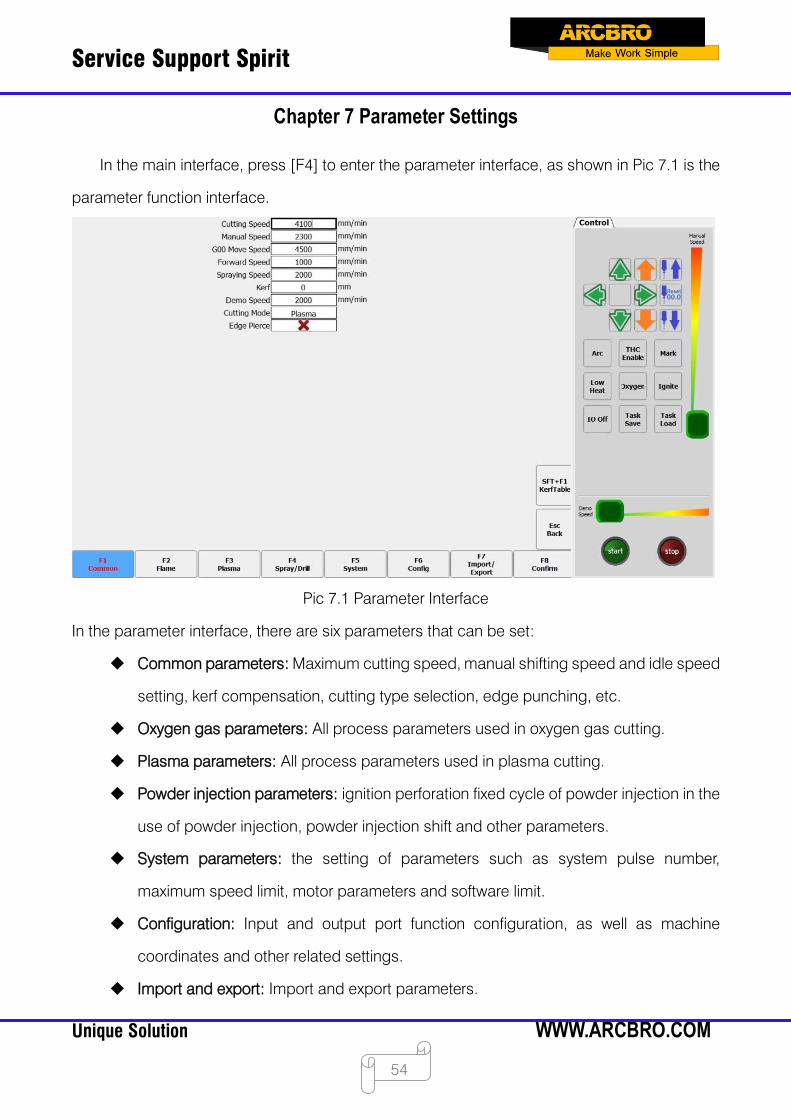
Chapter 7 Parameter Settings
In the main interface, press [F4] to enter the parameter interface, as shown in Pic 7.1 is the
parameter function interface.
Pic 7.1 Parameter Interface
In the parameter interface, there are six parameters that can be set:
Common parameters: Maximum cutting speed, manual shifting speed and idle speed
setting, kerf compensation, cutting type selection, edge punching, etc.
Oxygen gas parameters: All process parameters used in oxygen gas cutting.
Plasma parameters: All process parameters used in plasma cutting.
Powder injection parameters: ignition perforation fixed cycle of powder injection in the
use of powder injection, powder injection shift and other parameters.
System parameters: the setting of parameters such as system pulse number,
maximum speed limit, motor parameters and software limit.
Configuration: Input and output port function configuration, as well as machine
coordinates and other related settings.
Import and export: Import and export parameters.
Service Support Spirit
Unique Solution WWW.ARCBRO.COM
55
7.1 Common parameters
Pic 7.1 shows the common parameters of the system.
Cutting speed: the highest speed when cutting.
Manual shifting speed: the speed at which the torch moves when the torch is manually
moved.
Idle stroke shifting speed: the speed at which the torch moves when G00 or the torch
is quickly returned.
Advance/astern speed: the speed at which the path advances or retreats when paused
during cutting.
Powder injection speed: the speed at which the line is drawn through powder injection.
Kerf (half of kerf): The dimensional accuracy of the cut parts is guaranteed. The user
sets the kerf compensation value according to the kerf width (the kerf compensation
value should be half of the actual kerf width), and the system will automatically generate
a new cutting path to compensate for the kerf. The kerf value can be modified before a
workpiece is cut. After the cutting is started, the kerf value is not allowed to be modified.
Demo speed: cutting speed in demo mode.
Cutting type: aerobic gas and plasma are available. Users can choose between two
methods through the drop-down menu.
Edge perforation: choose whether to use edge perforation. When edge perforation is
used, the cutter automatically pauses whenever the M07 code is encountered. When
the cutter is paused, the user can manually move the torch to the edge of the steel plate
and then press the "Start" button, the system prompts:

Service Support Spirit
Unique Solution WWW.ARCBRO.COM
56
Pic 7.2 Edge Perforation
When [G] is selected, the system will cut from the current point ignition to the pause point
and then continue cutting. This is the function of edge perforation.
This function is especially useful when cutting thick steel plates. Thick steel plates are more
difficult to perforate and have larger holes. If they are directly perforated in the cutting path, they
may have an impact on the final product quality. The application of edge perforations can speed
up the perforation, save cutting time and improve product quality.
Of course, without the use of edge perforations, the use of lead-through perforations is also
a more effective method.
7.2 Oxygen gas parameter
Click [F2] on the parameter interface to switch to the oxygen gas parameter interface. As
shown in Pic 7.3.

Service Support Spirit
Unique Solution WWW.ARCBRO.COM
57
Pic 7.3 Oxygen Gas Parameters
Ignition time: during ignition, delay time when the high-pressure ignition switch is
turned on.
Low-pressure preheating delay: the time of low pressure preheating before
perforation. Input any value in the range of ≥0 (unit: second). During the preheating
process of the perforation, if the system is in the low pressure preheating phase, if
you feel that the preheating time is not enough, you can press the "Stop" button or
the [F7] button. When the stop button is pressed, the system starts to delay
indefinitely. The thermal delay will increase automatically. When the preheating is
completed, press the "Start" button to end the warm-up delay and start the high-
pressure preheating delay. After pressing the [F7] button, the preheating time will
automatically extend 15 seconds. And this time will be saved by the system.
High-pressure preheating delay: same as low-pressure preheating delay. Just IO
opened is different, the high-pressure preheating delay is before the low-pressure
preheating delay.

Service Support Spirit
Unique Solution WWW.ARCBRO.COM
58
Primary perforation time: low-pressure cutting oxygen perforation time. Input any
value in the range of ≥0 (unit: second). When it is greater than 0, the IO port will be
opened. If it is 0, the IO port will not be opened.
Secondary perforation time: middle-pressure cutting oxygen perforation time.
Input any value in the range of ≥0 (unit: second). When it is greater than 0, the IO
port will be opened. If it is 0, the IO port will not be opened.
Level-three perforation time: high-pressure cutting oxygen perforation time. Input any
value in the range of ≥0 (unit: second). When it is greater than 0, the IO port will be
opened. If it is 0, the IO port will not be opened.
Exhausting time: the delay in opening the exhaust when the gas is off. Input any value
in the range of ≥0 (unit: second).
Torch rise time: the time the torch rises when the cutting oxygen is turned off. Input
any value in the range of ≥0 (unit: second).
Torch lower time: the time the torch is lowered before preheating. Input any value in
the range of ≥0 (unit: second).
Perforation rise time: The time when the torch rises before the perforation which is
different from the torch rise time: the torch rise is the time when the torch rises when
the torch needs to move to another place at the end of the current cutting line in the
M08 code or M02 code; the perforation rise time is the time during which the torch
rises after preheating during the perforation fixed cycle in the M07 code.
Perforation lower time: The time when the torch is lowered during perforation, which
is different from the torch lower time: torch lower time is the torch lower time when
the cutting oxygen is not opened before preheating; perforation lower time is the
Service Support Spirit
Unique Solution WWW.ARCBRO.COM
59
torch lower time after the perforation rise is completed and the cutting oxygen is
opened during perforation fixing cycle.
Using heightening box: select whether to use the heightening box according to the
user equipment configuration.
M08 preheating oxygen holding output: If this parameter is set to "Yes", the low
pressure preheated oxygen IO port is always open during the cutting process before
the cutting is completed (i.e. before the M02 code is encountered). If "No" is selected,
the low pressure preheating will be turned off when M08 or M02 is encountered
during processing.
Cutting ending preheating oxygen output retention: if this parameter is set to "Yes",
the preheated oxygen is always on.
Number of perforations: record the number of perforations during the flame cutting
process.
Piece number: record the number of workpieces that have been flame cut.
Cutting distance: record the total flame cutting distance in metric - meter, British
system - foot.
Cutting time: record the time during the flame cutting process.
Operation time: record flame cutting time + idle time + M07 status time.
Crawl time: crawl time. See Article 7.2.1 Dynamic perforation and crawling.
Crawling speed: crawling speed. See Article 7.2.1 Dynamic perforation and crawling.
Service Support Spirit
Unique Solution WWW.ARCBRO.COM
60
7.2.1 Dynamic perforation and crawling
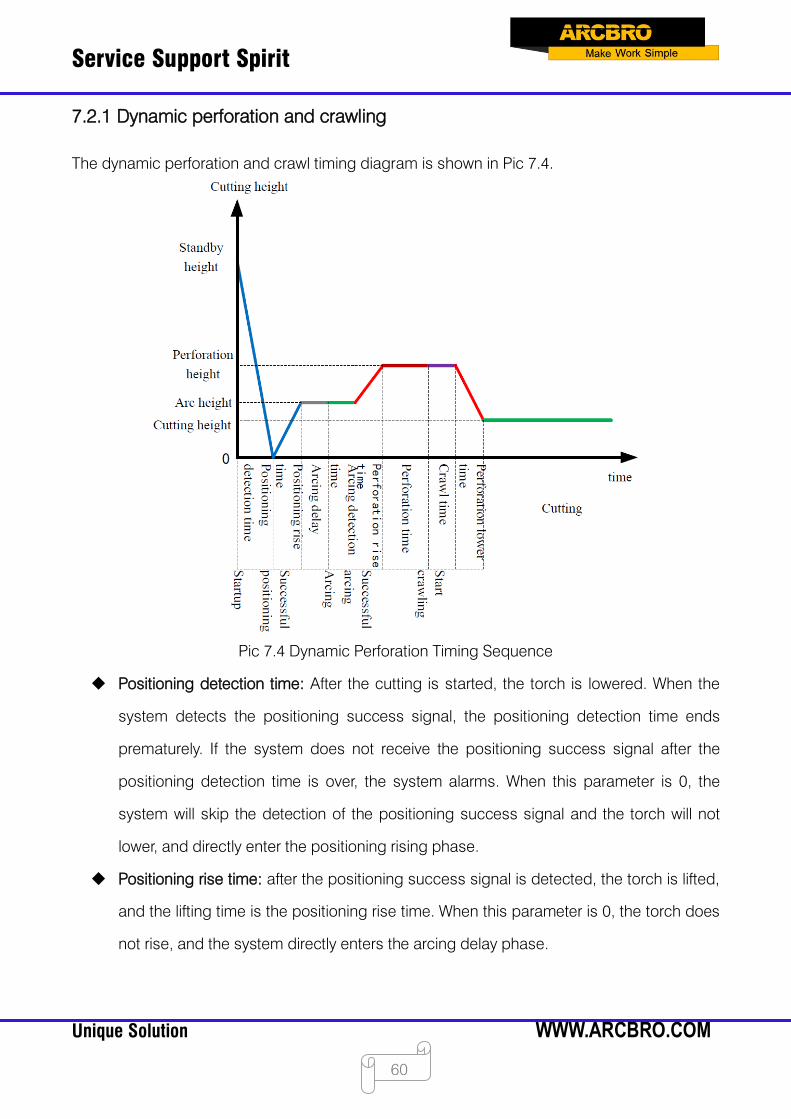
The dynamic perforation and crawl timing diagram is shown in Pic 7.4.
Pic 7.4 Dynamic Perforation Timing Sequence
Positioning detection time: After the cutting is started, the torch is lowered. When the
system detects the positioning success signal, the positioning detection time ends
prematurely. If the system does not receive the positioning success signal after the
positioning detection time is over, the system alarms. When this parameter is 0, the
system will skip the detection of the positioning success signal and the torch will not
lower, and directly enter the positioning rising phase.
Positioning rise time: after the positioning success signal is detected, the torch is lifted,
and the lifting time is the positioning rise time. When this parameter is 0, the torch does
not rise, and the system directly enters the arcing delay phase.
Service Support Spirit
Unique Solution WWW.ARCBRO.COM
61
Arcing delay: After the positioning rise time is over, the system will delay the arcing for a
while, which is defined as the arcing delay. When this parameter is 0, the system does
not delay and directly starts arcing.
Arcing detection time: After the arcing delay time is over, the system will open the arcing
port and start detecting the arcing success feedback signal. When the arcing success
return signal is detected, the arcing detection time ends early. If the system has not
received the arcing success feedback signal after the arcing detection time is over, the
system prompts an error and terminates the cutting of the current workpiece, and exits
the program according to the break-point memory. When the parameter is 0, the system
directly detects the arcing success feedback signal. If the signal is not detected, an error
will be reported. After the signal is detected, the system enters the next stage.
Perforation rise time: After the arc is successfully started, the torch starts to rise, and the
lifting time is the perforation rise time. When this parameter is 0, the torch does not rise
and the system goes directly to the next stage.
Perforation time: After the end of the perforation rise time, the system begins to statically
perforate, and the time of perforation is the perforation time. When this parameter is 0,
the system will skip this time and enter the crawling phase.
Crawl time: after the end of the static perforation, if there is more and higher slag
accumulation at the perforation point, the arc pressure will be unstable when cutting in
this area, and at the same time, in order to prevent the slag from blocking the torch.
Therefore, it is necessary to move forward for a period of time without prohibiting the
increase, which is the crawl time. When this parameter is 0, the system will skip this time
and enter the perforation lower phase.
Perforation lower time: At the end of the crawling time, the torch is lowered to the normal
cutting height to start cutting. This lower time is the perforation lower time. When this
parameter is 0, the torch does not drop and the normal cutting starts directly.

Service Support Spirit
Unique Solution WWW.ARCBRO.COM
62
7.3 Plasma parameter
As shown in Pic 7.5, it is the plasma parameter. These parameters need to be set when the
machine uses plasma cutting.
Pic 7.5 Plasma Parameters
Arcing detection time: The longest time to send an arcing command to accept feedback
to receive a command.
Arcing delay: The time the system waits before arcing. At this point, all outputs are
closed. Input any value in the range of ≥0 (unit: second).
Perforation delay: the perforation time, input any value in the range of ≥ 0 (the unit:
second).
Torch rise time: the time the torch rises before arc breaking. Input any value in the range
of ≥0 (unit: second).
Arcing detection time: Input any value in the range of ≥0 (unit: second). If the arcing
success feedback signal is not detected within the detection time, the system prompts

Service Support Spirit
Unique Solution WWW.ARCBRO.COM
63
an error message and terminates the cutting of the current workpiece, and exits the
program according to the break-point memory. If the successful arcing input signal is
detected within the arcing detection time, the system stops detecting and starts cutting.
Positioning detection time: Input any value in the range of ≥0 (unit: second). The time
used for the positioning detection. If the positioning success signal input is not detected
beyond this time, it is considered that the positioning is unsuccessful and the system
alarms. If the positioning success signal input is detected within the detection time, the
positioning detection is ended and the positioning starts to rise.
Positioning rise time: Input any value in the range of ≥0 (unit: second). If the positioning
success signal input is detected during the positioning detection, the torch lifting time.
Low speed off arc voltage adjustment (corner signal): This parameter is a percentage.
Open the "close arc voltage auto-adjustment" port at X% of the cutting speed to keep
the torch at a fixed height to prevent the arc height from changing at low speed and the
torch to be burnt in severe cases. Unit: %.
Close heightening minimum distance: The effect is the same as the low speed closing
arc voltage adjustment (corner signal). This signal is not turned off according to the
speed of the arc voltage, but according to the length of the line segment at the
beginning and end of the current machining curve. From the distance of "close the
height-adjusted minimum distance" at the beginning of the curve, and within the
distance of "close the height-adjusted minimum distance" before the end of the curve,
open the "close arc voltage auto-adjustment" port to keep the torch at a fixed height.
Heightening enabling delay after perforation: After the perforation is completed, the arc
voltage is unstable. At this time, the height is not adjusted. After the delay is set, the arc
voltage is stable and the height is increased.

Service Support Spirit
Unique Solution WWW.ARCBRO.COM
64
Arc breaking detection time: When the arc break occurs, the system delays the time of
"arc breaking detection delay". If the arc break still occurs, it is considered that the arc
break has occurred, stopping the machine operation and alarming. This function is
used to process the workpiece with the lead wire. After the delay time, the lead wire has
passed, and the plasma has not broken the arc, the next workpiece can be directly
processed. This function effectively prevents false arcing when cutting the lead wire.
Using air cylinder to heighten: When this parameter is selected, the cutting torch in the
cut keeps the output.
Cutting middle arcing voltage detection: If this option is selected, the continuity of the
arc voltage is detected during cutting, and an arc-breaking alarm is issued when the
arc voltage is lost.
M08 advance close arcing voltage time: Under normal circumstances, the plasma arc
voltage is turned off when M08 is encountered. When this value is greater than 0, the
plasma arc voltage is turned off before the M08 is encountered. Unit: s. Use this function
when cutting small circles or having lead wires.
Number of perforations: record the number of perforations during the plasma cutting
process.
Piece number: record the number of workpieces that have been plasma cut.
Cutting distance: record the total plasma cutting distance in metric - meter, British
system - foot.
Cutting time: record the time during the plasma cutting process.
Operation time: record plasma cutting time + idle time + M07 status time.
Crawl time: crawl time. See Article 7.2.1 Dynamic perforation and crawling.
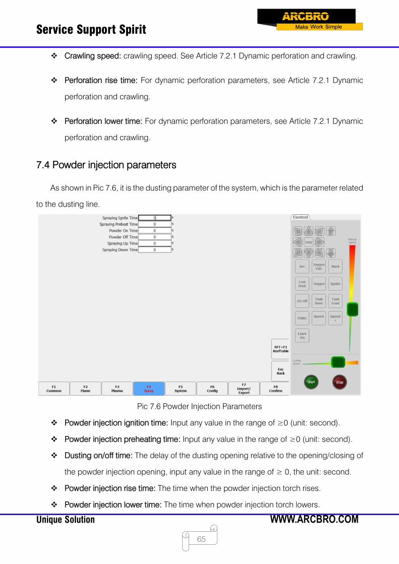
Service Support Spirit
Unique Solution WWW.ARCBRO.COM
65
Crawling speed: crawling speed. See Article 7.2.1 Dynamic perforation and crawling.
Perforation rise time: For dynamic perforation parameters, see Article 7.2.1 Dynamic
perforation and crawling.
Perforation lower time: For dynamic perforation parameters, see Article 7.2.1 Dynamic
perforation and crawling.
7.4 Powder injection parameters
As shown in Pic 7.6, it is the dusting parameter of the system, which is the parameter related
to the dusting line.
Pic 7.6 Powder Injection Parameters
Powder injection ignition time: Input any value in the range of ≥0 (unit: second).
Powder injection preheating time: Input any value in the range of ≥0 (unit: second).
Dusting on/off time: The delay of the dusting opening relative to the opening/closing of
the powder injection opening, input any value in the range of ≥ 0, the unit: second.
Powder injection rise time: The time when the powder injection torch rises.
Powder injection lower time: The time when powder injection torch lowers.
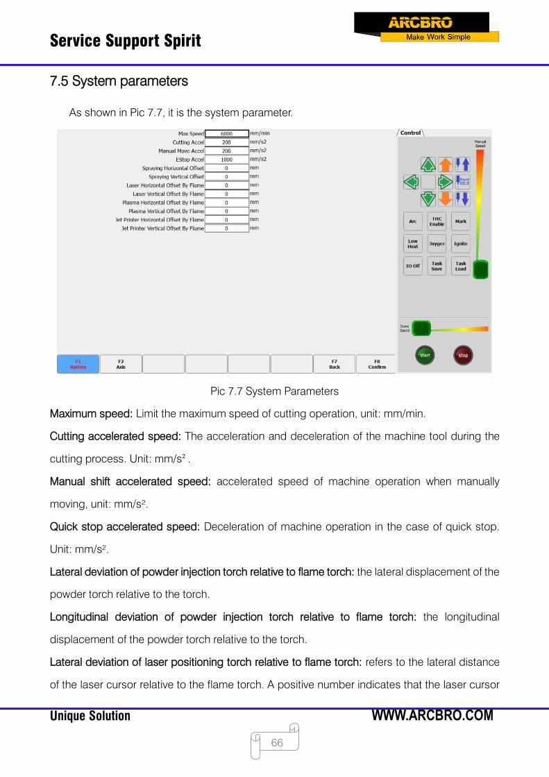
Service Support Spirit
Unique Solution WWW.ARCBRO.COM
66
7.5 System parameters
As shown in Pic 7.7, it is the system parameter.
Pic 7.7 System Parameters
Maximum speed: Limit the maximum speed of cutting operation, unit: mm/min.
Cutting accelerated speed: The acceleration and deceleration of the machine tool during the
cutting process. Unit: mm/s².
Manual shift accelerated speed: accelerated speed of machine operation when manually
moving, unit: mm/s².
Quick stop accelerated speed: Deceleration of machine operation in the case of quick stop.
Unit: mm/s².
Lateral deviation of powder injection torch relative to flame torch: the lateral displacement of the
powder torch relative to the torch.
Longitudinal deviation of powder injection torch relative to flame torch: the longitudinal
displacement of the powder torch relative to the torch.
Lateral deviation of laser positioning torch relative to flame torch: refers to the lateral distance
of the laser cursor relative to the flame torch. A positive number indicates that the laser cursor
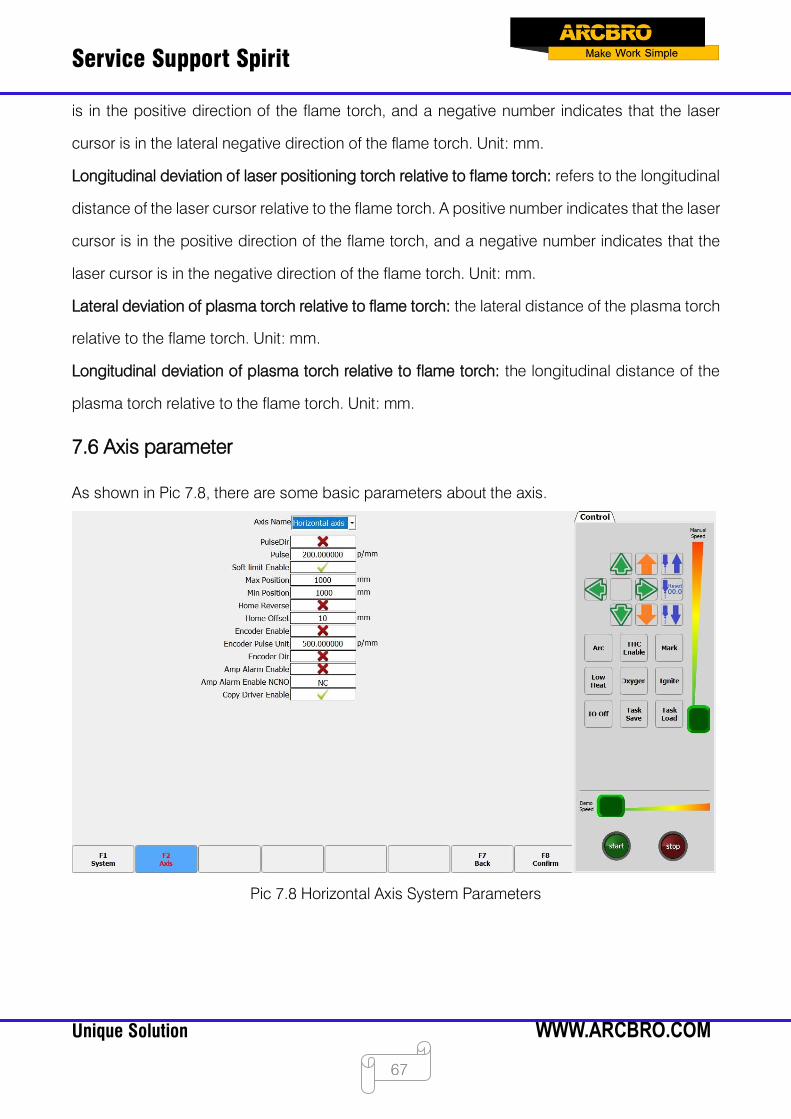
Service Support Spirit
Unique Solution WWW.ARCBRO.COM
67
is in the positive direction of the flame torch, and a negative number indicates that the laser
cursor is in the lateral negative direction of the flame torch. Unit: mm.
Longitudinal deviation of laser positioning torch relative to flame torch: refers to the longitudinal
distance of the laser cursor relative to the flame torch. A positive number indicates that the laser
cursor is in the positive direction of the flame torch, and a negative number indicates that the
laser cursor is in the negative direction of the flame torch. Unit: mm.
Lateral deviation of plasma torch relative to flame torch: the lateral distance of the plasma torch
relative to the flame torch. Unit: mm.
Longitudinal deviation of plasma torch relative to flame torch: the longitudinal distance of the
plasma torch relative to the flame torch. Unit: mm.
7.6 Axis parameter
As shown in Pic 7.8, there are some basic parameters about the axis.
Pic 7.8 Horizontal Axis System Parameters
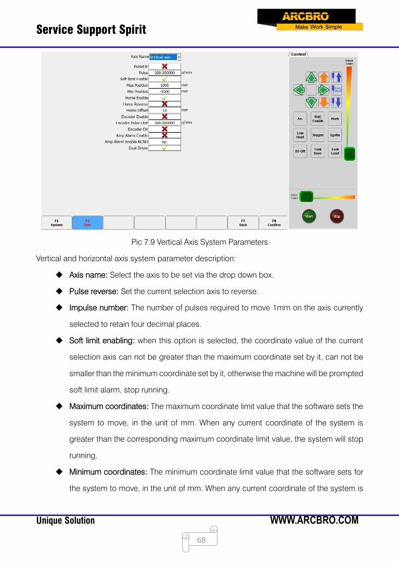
Service Support Spirit
Unique Solution WWW.ARCBRO.COM
68
Pic 7.9 Vertical Axis System Parameters
Vertical and horizontal axis system parameter description:
Axis name: Select the axis to be set via the drop down box.
Pulse reverse: Set the current selection axis to reverse.
Impulse number: The number of pulses required to move 1mm on the axis currently
selected to retain four decimal places.
Soft limit enabling: when this option is selected, the coordinate value of the current
selection axis can not be greater than the maximum coordinate set by it, can not be
smaller than the minimum coordinate set by it, otherwise the machine will be prompted
soft limit alarm, stop running.
Maximum coordinates: The maximum coordinate limit value that the software sets the
system to move, in the unit of mm. When any current coordinate of the system is
greater than the corresponding maximum coordinate limit value, the system will stop
running.
Minimum coordinates: The minimum coordinate limit value that the software sets for
the system to move, in the unit of mm. When any current coordinate of the system is

Service Support Spirit
Unique Solution WWW.ARCBRO.COM
69
less than the corresponding minimum coordinate limit value, the system will stop
running.
Bilateral drive: Open the dual drive function of the gantry shaft.
Zeroing reserve: The current axis returns zero in reverse direction.
Zeroing offset: The distance from the origin of the machine coordinate system to the
zeroing switch after zeroing. (>0) The setting is too small. After the zero return is
completed, the zero return switch status may still be triggered, and the limit alarm is
reported.
Encoder enabling: Use the encoder feedback coordinates as the feedback of the shaft
card.
Encoder pulse equivalent: pulse type corresponding when the encoder feedback
shaft moves 1mm.
Encoder reverse: The encoder feedback axis coordinate value is inversed.
Servo alarm enabling: turn on the servo alarm function.
Servo alarm enabling constant opening and closing: servo alarm type selection of
input port.
Double-trolley enabling: open double-trolley function.
7.7 System configuration
In the parameter setting interface, press [F6] to enter the system configuration interface.
Under this interface, you can set the system's input IO port, output IO port, System coordinates,
controller options, and IP.
7.7.1 Input port definition
The controller can change the definition of the input IO port according to the user's needs,
including changing the serial number of the IO port on the input terminal, and the normally open
or normally closed type of the input port. As shown in Pic 7.9.

Service Support Spirit
Unique Solution WWW.ARCBRO.COM
70
Pic 7.10 Input Port Definition
In this interface, use the arrow buttons [↑], [↓], [←], [→] to position the cursor to the
option to be modified, press [Enter] to open the tab of the drop-down box where the cursor is
located, and through [↑] , [↓], move the cursor, press [Enter] again to set the selected
parameter.
Number: 01 - 16.
Type: NO is normally open, NC is normally closed.
7.7.2 Output port definition
This controller can change the definition of the output port according to the user's
requirement: the sequence number of the output port on the output terminal and the normally
closed type. As shown in Pic 7.10.
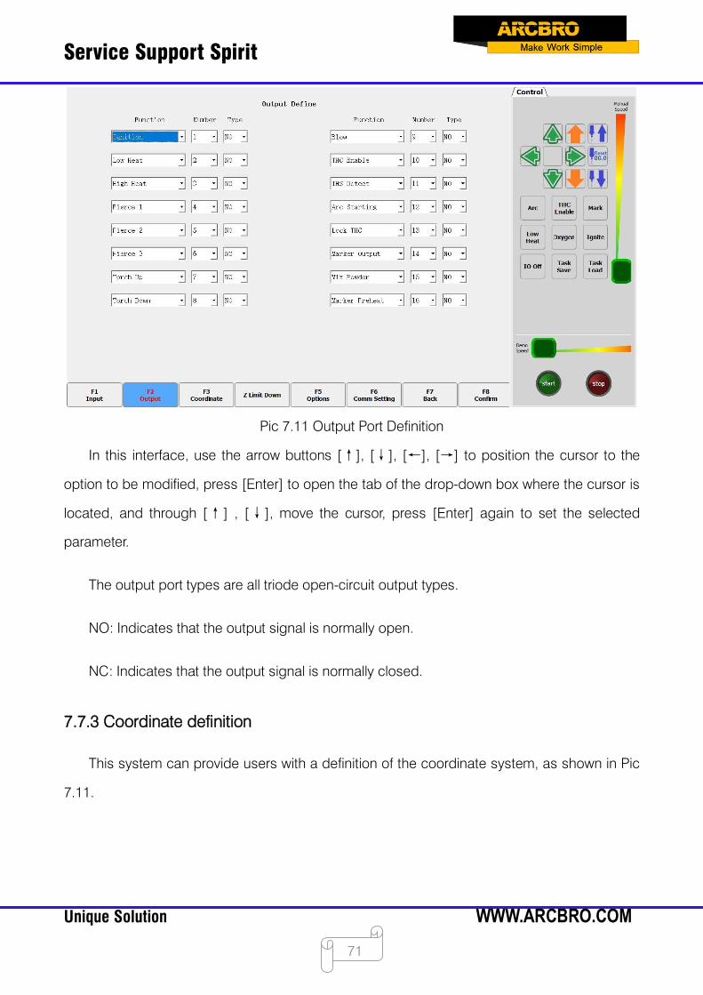
Service Support Spirit
Unique Solution WWW.ARCBRO.COM
71
Pic 7.11 Output Port Definition
In this interface, use the arrow buttons [↑], [↓], [←], [→] to position the cursor to the
option to be modified, press [Enter] to open the tab of the drop-down box where the cursor is
located, and through [↑] , [↓], move the cursor, press [Enter] again to set the selected
parameter.
The output port types are all triode open-circuit output types.
NO: Indicates that the output signal is normally open.
NC: Indicates that the output signal is normally closed.
7.7.3 Coordinate definition
This system can provide users with a definition of the coordinate system, as shown in Pic
7.11.
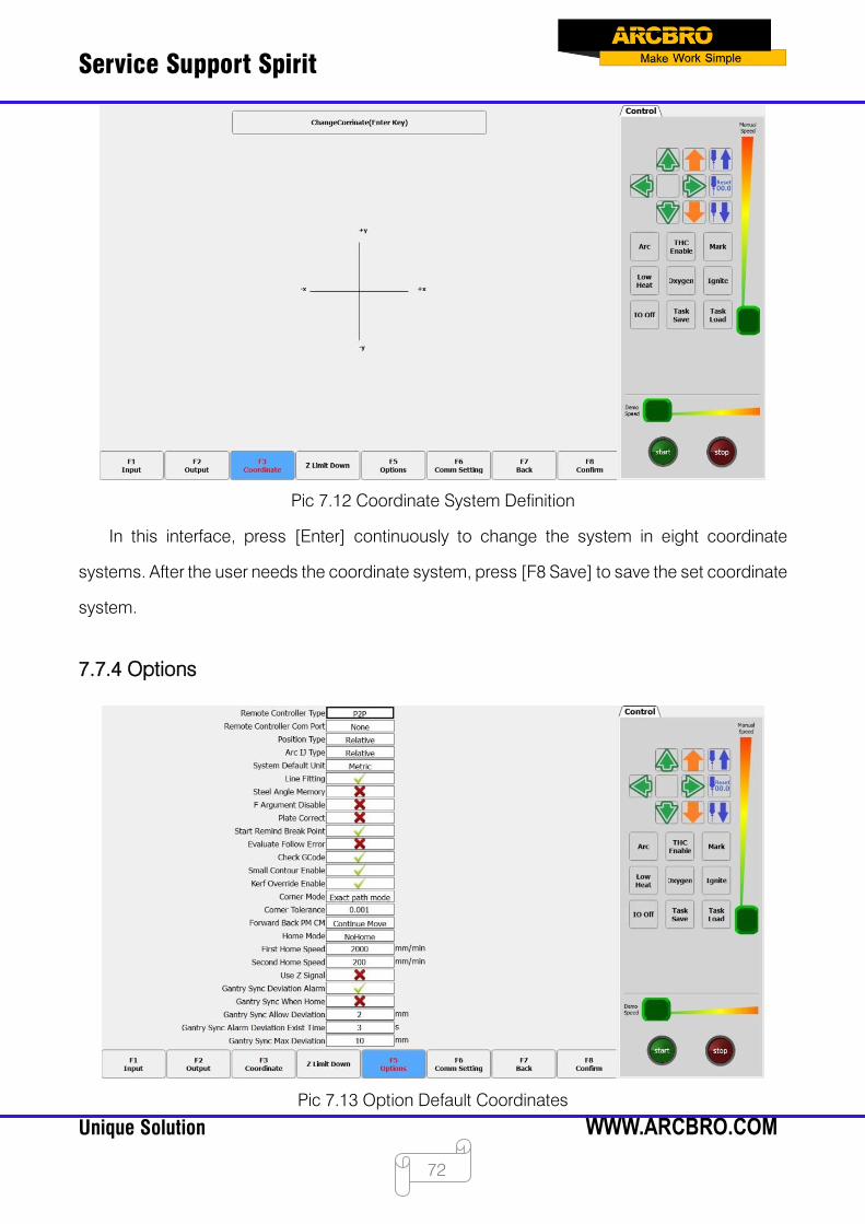
Service Support Spirit
Unique Solution WWW.ARCBRO.COM
72
Pic 7.12 Coordinate System Definition
In this interface, press [Enter] continuously to change the system in eight coordinate
systems. After the user needs the coordinate system, press [F8 Save] to save the set coordinate
system.
7.7.4 Options
Pic 7.13 Option Default Coordinates
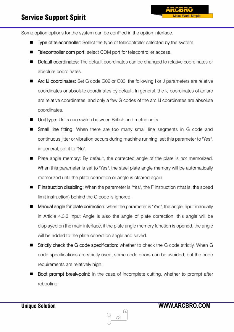
Service Support Spirit
Unique Solution WWW.ARCBRO.COM
73
Some option options for the system can be conPicd in the option interface.
Type of telecontroller: Select the type of telecontroller selected by the system.
Telecontroller com port: select COM port for telecontroller access.
Default coordinates: The default coordinates can be changed to relative coordinates or
absolute coordinates.
Arc IJ coordinates: Set G code G02 or G03, the following I or J parameters are relative
coordinates or absolute coordinates by default. In general, the IJ coordinates of an arc
are relative coordinates, and only a few G codes of the arc IJ coordinates are absolute
coordinates.
Unit type: Units can switch between British and metric units.
Small line fitting: When there are too many small line segments in G code and
continuous jitter or vibration occurs during machine running, set this parameter to "Yes",
in general, set it to "No".
Plate angle memory: By default, the corrected angle of the plate is not memorized.
When this parameter is set to "Yes", the steel plate angle memory will be automatically
memorized until the plate correction or angle is cleared again.
F instruction disabling: When the parameter is "Yes", the F instruction (that is, the speed
limit instruction) behind the G code is ignored.
Manual angle for plate correction: when the parameter is "Yes", the angle input manually
in Article 4.3.3 Input Angle is also the angle of plate correction, this angle will be
displayed on the main interface, if the plate angle memory function is opened, the angle
will be added to the plate correction angle and saved.
Strictly check the G code specification: whether to check the G code strictly. When G
code specifications are strictly used, some code errors can be avoided, but the code
requirements are relatively high.
Boot prompt break-point: in the case of incomplete cutting, whether to prompt after
rebooting.
Service Support Spirit
Unique Solution WWW.ARCBRO.COM
74
Follow the error measurement: the hardware is connected to the encoder, and the shaft
parameter uses the encoder. The interface draws the trajectory graph using the
coordinates fed back by the encoder.
Slot coverage enabling: whether the parameters for slot modification behind G41, G42,
and G43 work.
Corner way: choose the way of corner of machine tool.
Corner tolerance: Use the arc to fit the corner accuracy, the lower the value, the closer
to the sharp angle, but the more obvious deceleration.
Forward and backward jog and linkage: used to control the forward and backward
mode of cutting.
Zeroing mode: Select the zeroing mode of the machine tool.
Primary zeroing speed: zeroing parameters: the speed at which zeroing switch is
quickly found.
Secondary zeroing speed: zeroing parameter: Slow approach zeroing speed.
Use Z signal: When returning to zero, return to zero using the Z trust number.
Gantry synchronization error alarm: Open gantry synchronization error check function.
Gantry synchronization when zeroing: return to zero after the completion, it will
automatically perform gantry synchronization function. Need to turn on parameters:
return to zero using Z-phase number, shaft open encoder feedback.
Gantry synchronization allowance error: The value of the gantry's error, and it lasts for a
certain time (gantry's synchronization error duration). The machine will generate an
alarm.
Duration of the gantry synchronization error: the value of the gantry error (the gantry
synchronization error) and the duration of a certain amount of time. The machine will
generate an alarm.
Maximum error of gantry synchronization: The maximum deviation allowed in the
execution of gantry synchronization after the function of gantry synchronization is
enabled. Once the error reaches this value, the machine immediately stops running.
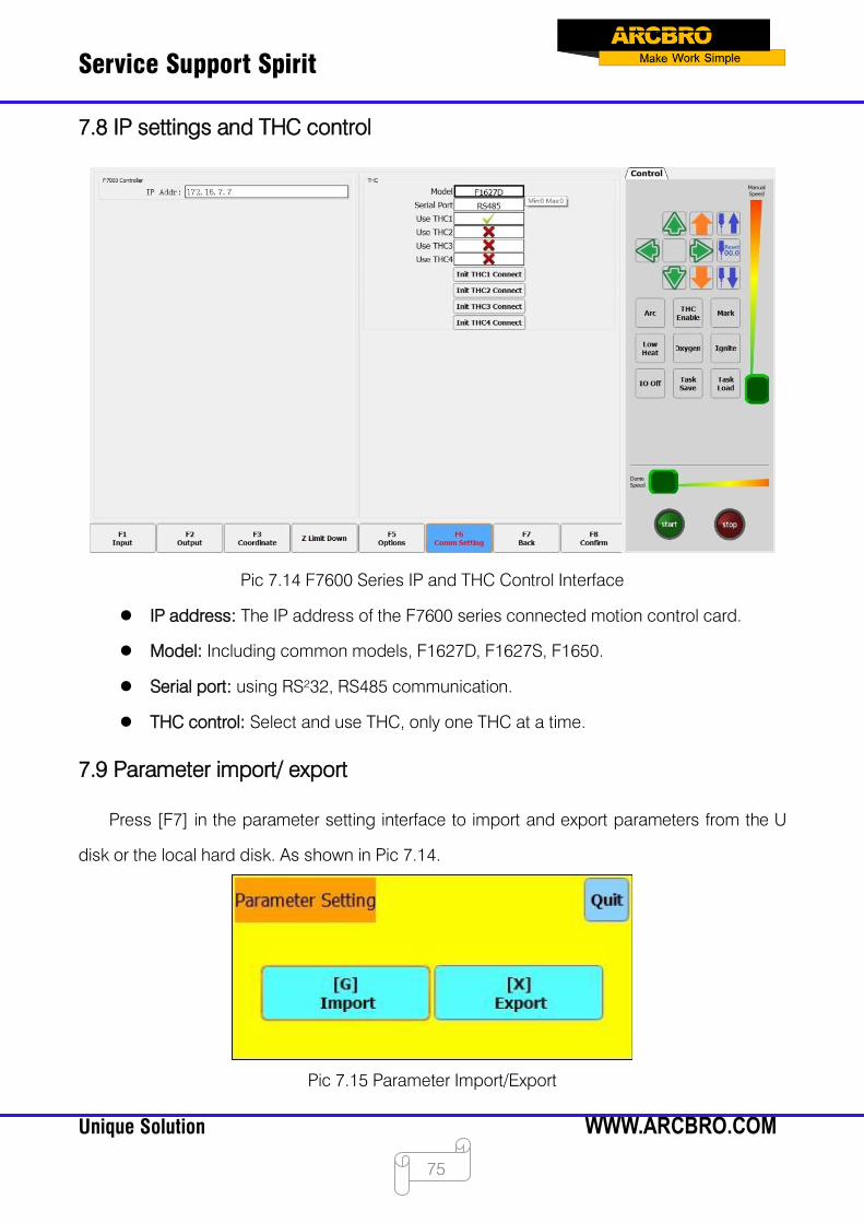
Service Support Spirit
Unique Solution WWW.ARCBRO.COM
75
7.8 IP settings and THC control
Pic 7.14 F7600 Series IP and THC Control Interface
IP address: The IP address of the F7600 series connected motion control card.
Model: Including common models, F1627D, F1627S, F1650.
Serial port: using RS²32, RS485 communication.
THC control: Select and use THC, only one THC at a time.
7.9 Parameter import/ export
Press [F7] in the parameter setting interface to import and export parameters from the U
disk or the local hard disk. As shown in Pic 7.14.
Pic 7.15 Parameter Import/Export

Service Support Spirit
Unique Solution WWW.ARCBRO.COM
76
Select [X] to export the parameters and the dialog box in Pic 7.14 will pop up. After selecting
the exported location, click [F8 Confirmation] to save all parameters of the current system to the
target location. When exporting, you can modify the exported file name.
Pic 7.16 Parameter Export
Select [G] to import parameters, you can load the saved parameter file. Combined with the
parameter export function, it is convenient for the user to save the parameters of different
materials and thicknesses into parameter files, and when needed, directly load the
corresponding parameter files.
Pic 7.17 Parameter Import
After modifying the parameters, press [F8] to save.
Caution: After any parameter has been modified, it must be saved if the modified parameter
is to take effect. Otherwise, the system will continue to use the parameter that was not modified.

Service Support Spirit
Unique Solution WWW.ARCBRO.COM
77
Chapter 8 Diagnostic Functions
Press [F5] on the main interface to enter the system diagnosis interface, as shown in Pic
8.1. In the diagnostic interface, you can diagnose the input and output of the system.
8.1 Input diagnostics
In this interface, the system will read the information of the current input IO and display the
status information of the current input IO. Green "●" indicates that the input is valid, and red "
●" indicates that the input is invalid. It can be used to test the status of the input port.
Pic 8.1 Input Port Diagnosis
8.2 Output diagnostics
In the diagnosis interface, press [F2] to enter the output diagnosis interface, as shown in
Pic 8.2.
Press [↑], [↓], [←], [→] to move the cursor to the corresponding output port, press [F3]
to open the corresponding output port, and press [F4] to close the corresponding output port.
The green "●" indicates that the output is valid, and the red "●" indicates that the output is
invalid. It can be used to test whether the output port can work normally.
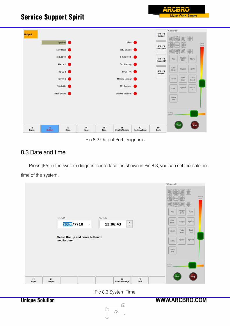
Service Support Spirit
Unique Solution WWW.ARCBRO.COM
78
Pic 8.2 Output Port Diagnosis
8.3 Date and time
Press [F5] in the system diagnostic interface, as shown in Pic 8.3, you can set the date and
time of the system.
Pic 8.3 System Time
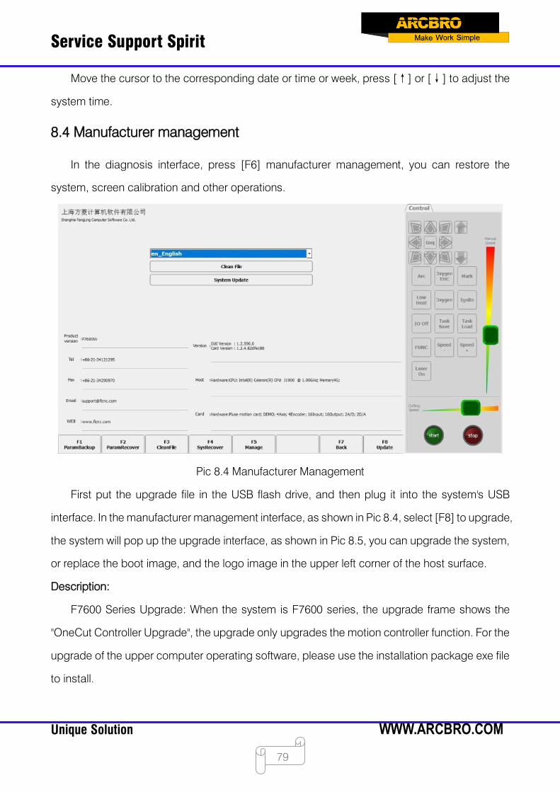
Service Support Spirit
Unique Solution WWW.ARCBRO.COM
79
Move the cursor to the corresponding date or time or week, press [↑] or [↓] to adjust the
system time.
8.4 Manufacturer management
In the diagnosis interface, press [F6] manufacturer management, you can restore the
system, screen calibration and other operations.
Pic 8.4 Manufacturer Management
First put the upgrade file in the USB flash drive, and then plug it into the system's USB
interface. In the manufacturer management interface, as shown in Pic 8.4, select [F8] to upgrade,
the system will pop up the upgrade interface, as shown in Pic 8.5, you can upgrade the system,
or replace the boot image, and the logo image in the upper left corner of the host surface.
Description:
F7600 Series Upgrade: When the system is F7600 series, the upgrade frame shows the
"OneCut Controller Upgrade", the upgrade only upgrades the motion controller function. For the
upgrade of the upper computer operating software, please use the installation package exe file
to install.
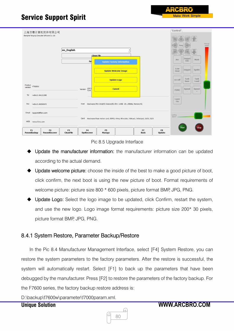
Service Support Spirit
Unique Solution WWW.ARCBRO.COM
80
Pic 8.5 Upgrade Interface
Update the manufacturer information: the manufacturer information can be updated
according to the actual demand.
Update welcome picture: choose the inside of the best to make a good picture of boot,
click confirm, the next boot is using the new picture of boot. Format requirements of
welcome picture: picture size 800 * 600 pixels, picture format BMP, JPG, PNG.
Update Logo: Select the logo image to be updated, click Confirm, restart the system,
and use the new logo. Logo image format requirements: picture size 200* 30 pixels,
picture format BMP, JPG, PNG.
8.4.1 System Restore, Parameter Backup/Restore
In the Pic 8.4 Manufacturer Management Interface, select [F4] System Restore, you can
restore the system parameters to the factory parameters. After the restore is successful, the
system will automatically restart. Select [F1] to back up the parameters that have been
debugged by the manufacturer. Press [F2] to restore the parameters of the factory backup. For
the F7600 series, the factory backup restore address is:
D:\backup\f7600w\parameter\f7000param.xml.
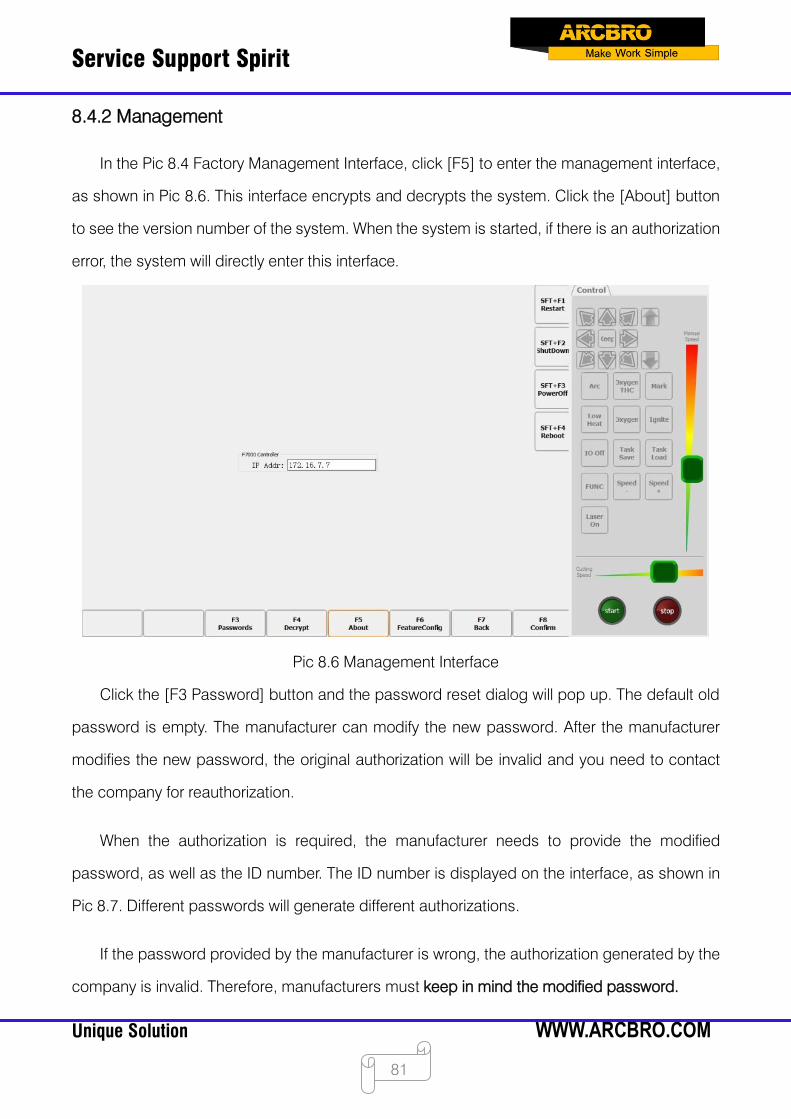
Service Support Spirit
Unique Solution WWW.ARCBRO.COM
81
8.4.2 Management
In the Pic 8.4 Factory Management Interface, click [F5] to enter the management interface,
as shown in Pic 8.6. This interface encrypts and decrypts the system. Click the [About] button
to see the version number of the system. When the system is started, if there is an authorization
error, the system will directly enter this interface.
Pic 8.6 Management Interface
Click the [F3 Password] button and the password reset dialog will pop up. The default old
password is empty. The manufacturer can modify the new password. After the manufacturer
modifies the new password, the original authorization will be invalid and you need to contact
the company for reauthorization.
When the authorization is required, the manufacturer needs to provide the modified
password, as well as the ID number. The ID number is displayed on the interface, as shown in
Pic 8.7. Different passwords will generate different authorizations.
If the password provided by the manufacturer is wrong, the authorization generated by the
company is invalid. Therefore, manufacturers must keep in mind the modified password.

Service Support Spirit
Unique Solution WWW.ARCBRO.COM
82
Pic 8.7 About Interface
After the authorization expires, click [F4] to pop up the decryption dialog box. Enter a new
authorization code to re-authorize. After the authorization is successful, the number of
authorized days of the decryption dialog is updated.
8.4.3 File clean up
In Pic 8.4 Manufacturer Management Interface, select [F3] to delete the file, you can clean
all the G code files in the current system.
8.5 Rocker calibration
As shown in the Diagnostic Interface shown in Pic 8.1, press F7 to enter the rocker
calibration interface, as shown in Pic 8.8:
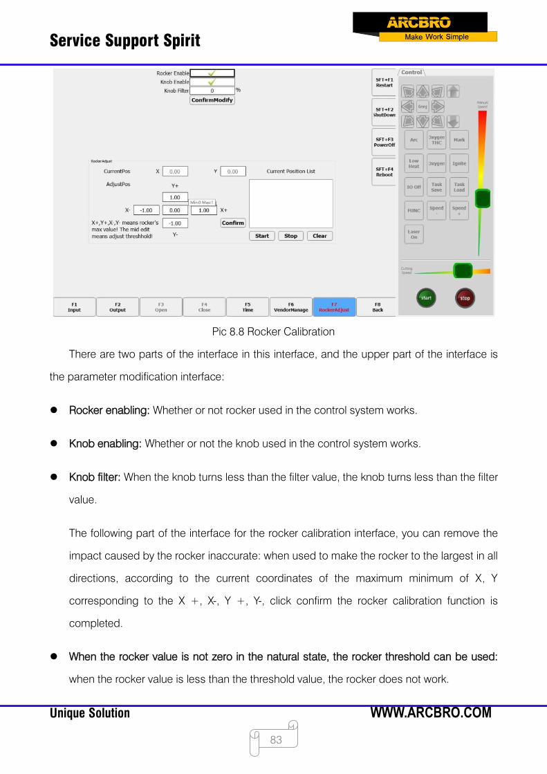
Service Support Spirit
Unique Solution WWW.ARCBRO.COM
83
Pic 8.8 Rocker Calibration
There are two parts of the interface in this interface, and the upper part of the interface is
the parameter modification interface:
Rocker enabling: Whether or not rocker used in the control system works.
Knob enabling: Whether or not the knob used in the control system works.
Knob filter: When the knob turns less than the filter value, the knob turns less than the filter
value.
The following part of the interface for the rocker calibration interface, you can remove the
impact caused by the rocker inaccurate: when used to make the rocker to the largest in all
directions, according to the current coordinates of the maximum minimum of X, Y
corresponding to the X +, X-, Y +, Y-, click confirm the rocker calibration function is
completed.
When the rocker value is not zero in the natural state, the rocker threshold can be used:
when the rocker value is less than the threshold value, the rocker does not work.
Service Support Spirit
Unique Solution WWW.ARCBRO.COM
84
8.6 Program restart and shutdown
On the right side of the system diagnostic interface shown in Pic 8.1, there are two buttons
[Restart Program] [Close Program]. The function of restarting and closing the program can be
realized by these two buttons.
8.7 Power off
As shown in the right side of the System Diagnostic Interface in Pic 8.1, the system can be
turned off by this button [SFT+F3 Shutdown].
8.8 Restarting shaft card
On the right side of the system diagnostic interface shown in Pic 8.1, there is a button
[SFT+F4 Restart Axis Card]. The function of restarting the axis card can be realized by this
button.
When this function is used, the program must be connected to the axis card, otherwise
there will be an error reminder. After the axis card restarts successfully, the program will restart
automatically.
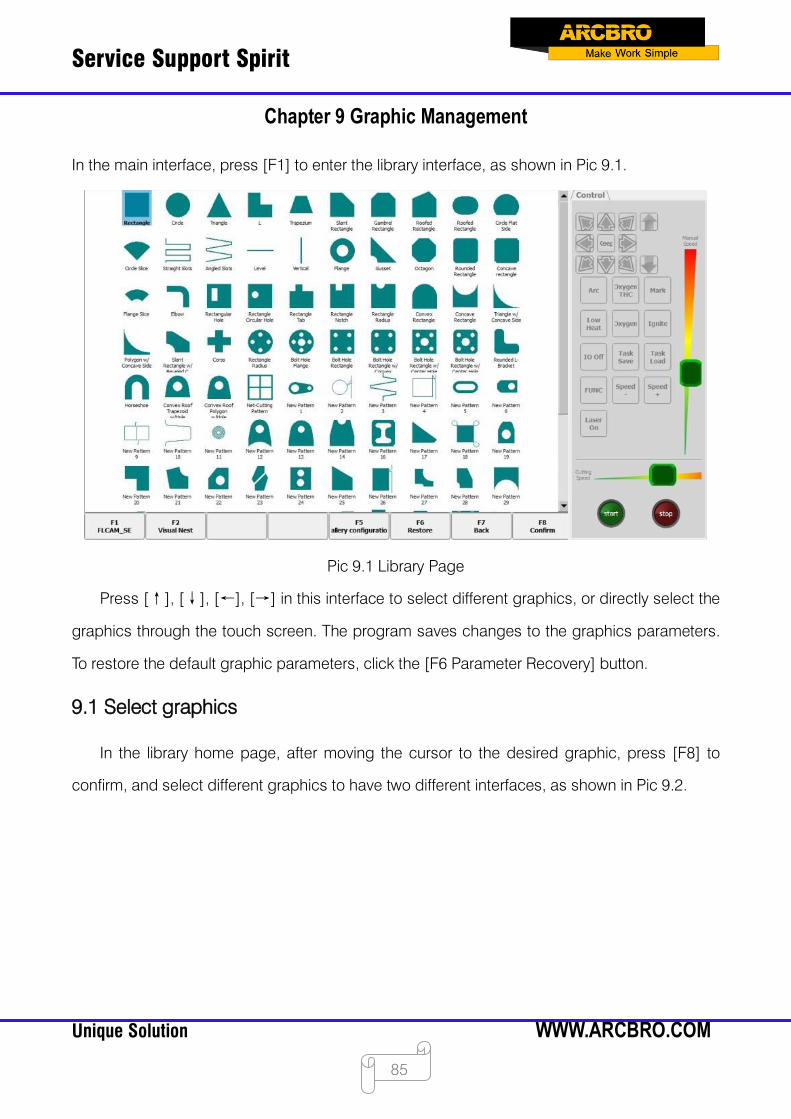
Service Support Spirit
Unique Solution WWW.ARCBRO.COM
85
Chapter 9 Graphic Management
In the main interface, press [F1] to enter the library interface, as shown in Pic 9.1.
Pic 9.1 Library Page
Press [↑], [↓], [←], [→] in this interface to select different graphics, or directly select the
graphics through the touch screen. The program saves changes to the graphics parameters.
To restore the default graphic parameters, click the [F6 Parameter Recovery] button.
9.1 Select graphics
In the library home page, after moving the cursor to the desired graphic, press [F8] to
confirm, and select different graphics to have two different interfaces, as shown in Pic 9.2.
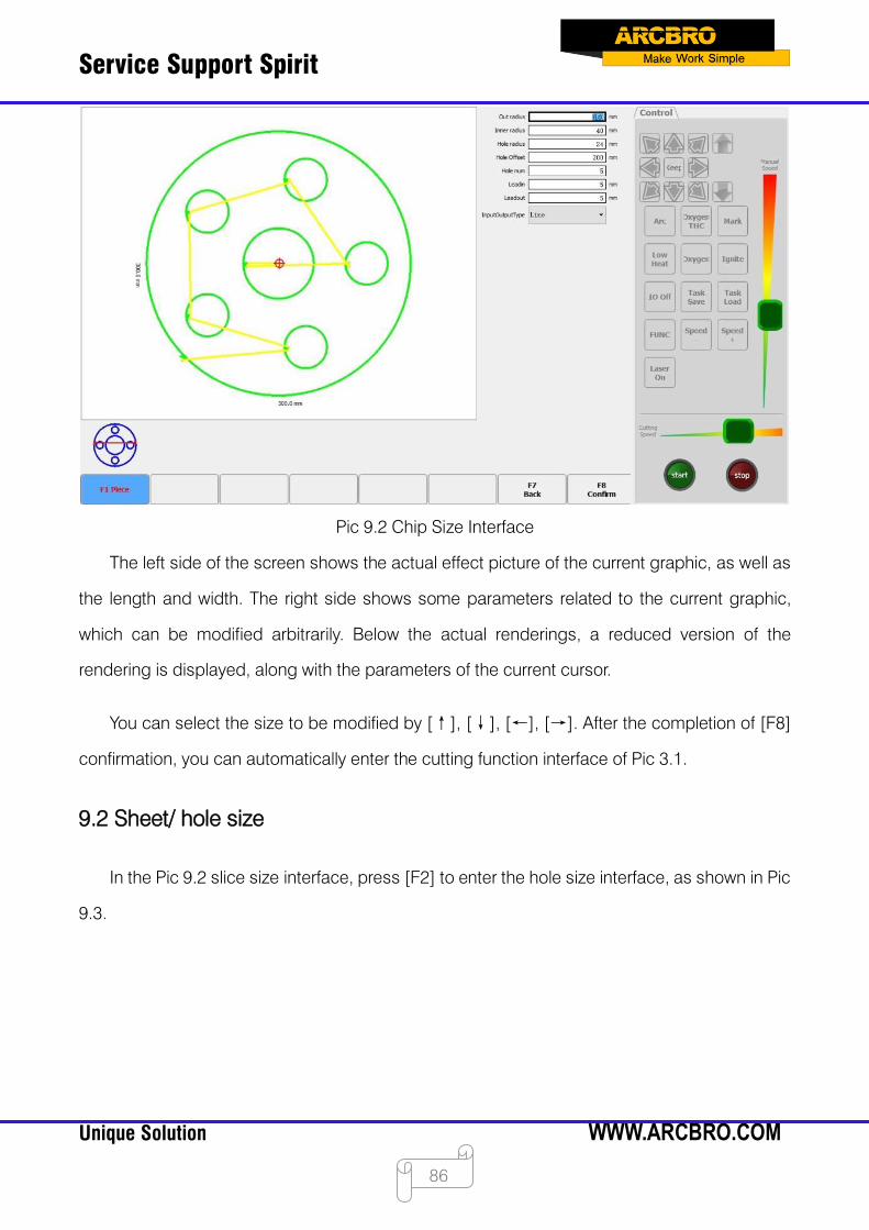
Service Support Spirit
Unique Solution WWW.ARCBRO.COM
86
Pic 9.2 Chip Size Interface
The left side of the screen shows the actual effect picture of the current graphic, as well as
the length and width. The right side shows some parameters related to the current graphic,
which can be modified arbitrarily. Below the actual renderings, a reduced version of the
rendering is displayed, along with the parameters of the current cursor.
You can select the size to be modified by [↑], [↓], [←], [→]. After the completion of [F8]
confirmation, you can automatically enter the cutting function interface of Pic 3.1.
9.2 Sheet/ hole size
In the Pic 9.2 slice size interface, press [F2] to enter the hole size interface, as shown in Pic
9.3.

Service Support Spirit
Unique Solution WWW.ARCBRO.COM
87
Pic 9.3 Hole Size
Modify the parameters to the same size. After the modification is completed, [F8] confirms,
and you can also enter the cutting function interface in Pic 3.1.
9.3 Chain cutting
The controller can realize the chain cutting function of the graphic library, and the chain
cutting can reduce the piercing point, improve the cutting quality, reduce the number of piercing
times and improve the efficiency when the flame is cut.
9.4 Use nesting software FLCAM
F7600 series system if FLCAM nesting software is installed. When you open the library
interface, the FLCAM_SE button will appear in the lower left corner of the interface, as shown in
Pic 9.4. Clicking this button will open FLCAM.
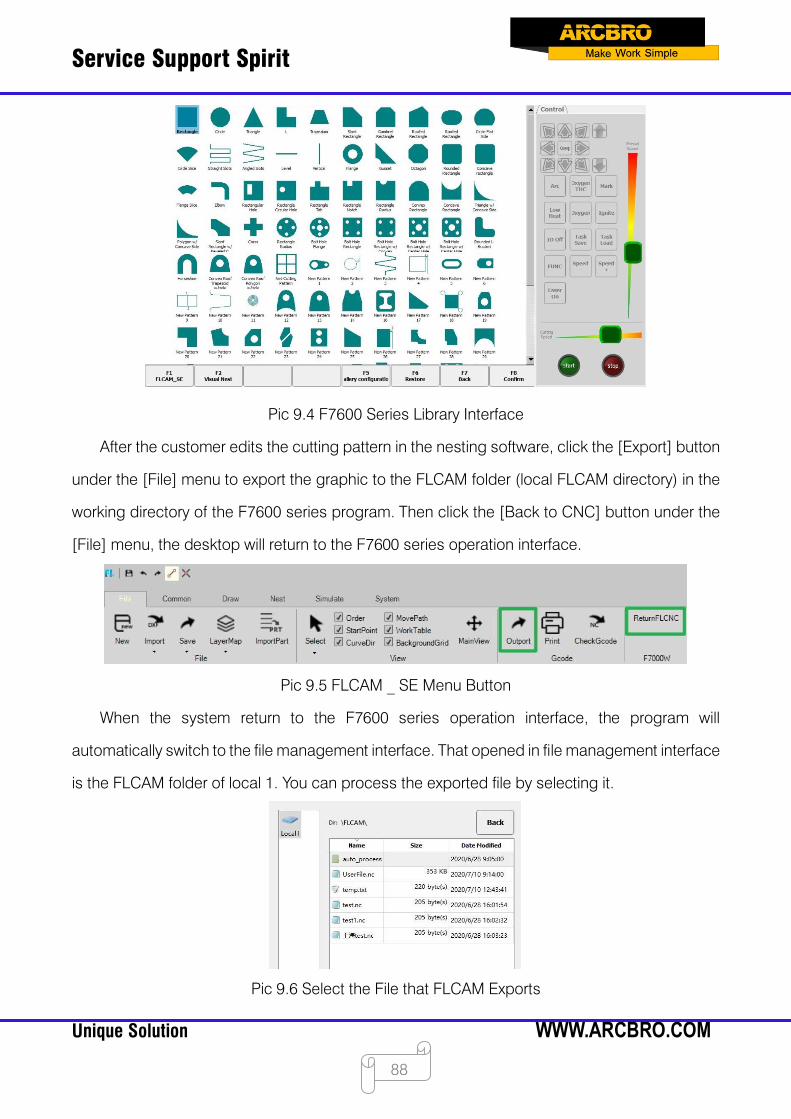
Service Support Spirit
Unique Solution WWW.ARCBRO.COM
88
Pic 9.4 F7600 Series Library Interface
After the customer edits the cutting pattern in the nesting software, click the [Export] button
under the [File] menu to export the graphic to the FLCAM folder (local FLCAM directory) in the
working directory of the F7600 series program. Then click the [Back to CNC] button under the
[File] menu, the desktop will return to the F7600 series operation interface.
Pic 9.5 FLCAM _ SE Menu Button
When the system return to the F7600 series operation interface, the program will
automatically switch to the file management interface. That opened in file management interface
is the FLCAM folder of local 1. You can process the exported file by selecting it.
Pic 9.6 Select the File that FLCAM Exports
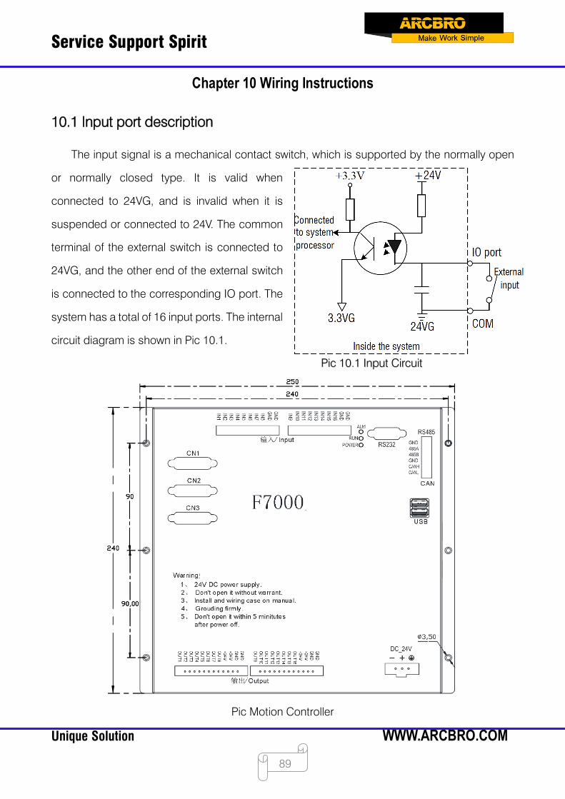
Service Support Spirit
Unique Solution WWW.ARCBRO.COM
89
Chapter 10 Wiring Instructions
10.1 Input port description
The input signal is a mechanical contact switch, which is supported by the normally open
or normally closed type. It is valid when
connected to 24VG, and is invalid when it is
suspended or connected to 24V. The common
terminal of the external switch is connected to
24VG, and the other end of the external switch
is connected to the corresponding IO port. The
system has a total of 16 input ports. The internal
circuit diagram is shown in Pic 10.1.
Pic Motion Controller
Pic 10.1 Input Circuit
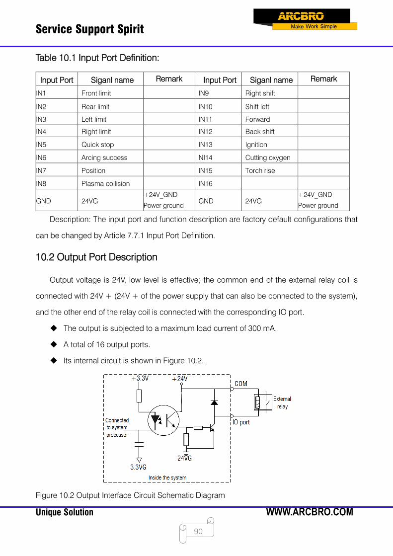
Service Support Spirit
Unique Solution WWW.ARCBRO.COM
90
Table 10.1 Input Port Definition:
Description: The input port and function description are factory default configurations that
can be changed by Article 7.7.1 Input Port Definition.
10.2 Output Port Description
Output voltage is 24V, low level is effective; the common end of the external relay coil is
connected with 24V + (24V + of the power supply that can also be connected to the system),
and the other end of the relay coil is connected with the corresponding IO port.
The output is subjected to a maximum load current of 300 mA.
A total of 16 output ports.
Its internal circuit is shown in Figure 10.2.
Figure 10.2 Output Interface Circuit Schematic Diagram
Input Port Siganl name Remark Input Port Siganl name Remark
IN1 Front limit IN9 Right shift
IN2 Rear limit IN10 Shift left
IN3 Left limit IN11 Forward
IN4 Right limit IN12 Back shift
IN5 Quick stop IN13 Ignition
IN6 Arcing success NI14 Cutting oxygen
IN7 Position IN15 Torch rise
IN8 Plasma collision IN16
GND 24VG +24V_GND
Power ground GND 24VG
+24V_GND
Power ground

Service Support Spirit
Unique Solution WWW.ARCBRO.COM
91
Table 10.2 Output Port Definition:
Description: Output port and function description is factory default configuration, can be
changed through Article 7.7.2 output port definition.
10.3 Motor interface description
The system has a total of six motor interfaces. The first four motor interfaces are identical
and support the encoder function. A DB port is a motor interface. The latter two motor interfaces
do not support encoders, and they are defined in the same DB port.
Output Port
Siganl name Remark Output Port
Siganl name Remark
OUT 1 Ignition OUT 9 Exhaust vent
OUT 2 Low pressure
preheating OUT 10
Height adjustment
box enabling
OUT 3 High pressure
preheating OUT 11 Plasma positioning
OUT 4 Low pressure cutting
Oxygen OUT 12 Plasma arcing
OUT 5 Medium pressure
cutting oxygen OUT 13
Turn off heightening
(corner signal)
OUT 6 High pressure cutting
oxygen OUT 14 Powder injection
OUT 7 Torch rise OUT 15 Dusting
OUT 8 Torch down OUT 16 Powder injection
preheating
+24V +24V +24V/3A Power
output +24V +24V
+24V/3A Power
output
GND 24VG +24V_GND
Power ground GND 24VG
+24V_GND
Power ground
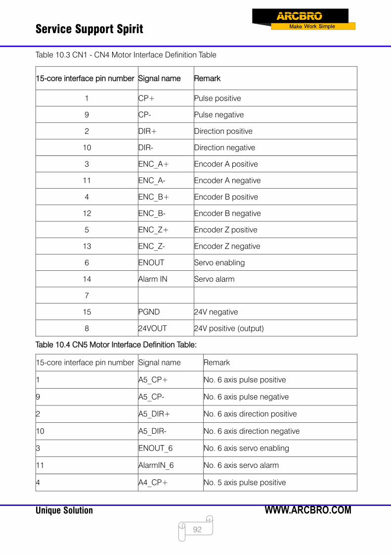
Service Support Spirit
Unique Solution WWW.ARCBRO.COM
92
Table 10.3 CN1 - CN4 Motor Interface Definition Table
Table 10.4 CN5 Motor Interface Definition Table:
15-core interface pin number Signal name Remark
1 CP+ Pulse positive
9 CP- Pulse negative
2 DIR+ Direction positive
10 DIR- Direction negative
3 ENC_A+ Encoder A positive
11 ENC_A- Encoder A negative
4 ENC_B+ Encoder B positive
12 ENC_B- Encoder B negative
5 ENC_Z+ Encoder Z positive
13 ENC_Z- Encoder Z negative
6 ENOUT Servo enabling
14 Alarm IN Servo alarm
7
15 PGND 24V negative
8 24VOUT 24V positive (output)
15-core interface pin number Signal name Remark
1 A5_CP+ No. 6 axis pulse positive
9 A5_CP- No. 6 axis pulse negative
2 A5_DIR+ No. 6 axis direction positive
10 A5_DIR- No. 6 axis direction negative
3 ENOUT_6 No. 6 axis servo enabling
11 AlarmIN_6 No. 6 axis servo alarm
4 A4_CP+ No. 5 axis pulse positive
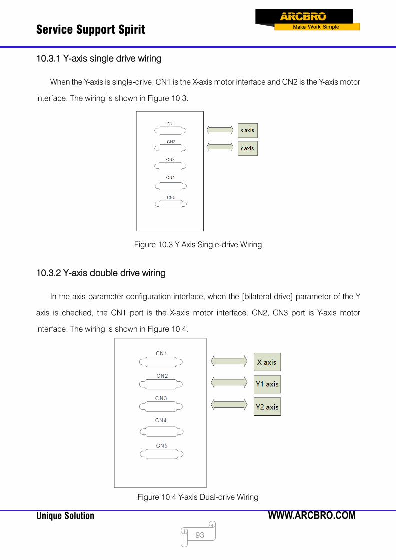
Service Support Spirit
Unique Solution WWW.ARCBRO.COM
93
10.3.1 Y-axis single drive wiring
When the Y-axis is single-drive, CN1 is the X-axis motor interface and CN2 is the Y-axis motor
interface. The wiring is shown in Figure 10.3.
Figure 10.3 Y Axis Single-drive Wiring
10.3.2 Y-axis double drive wiring
In the axis parameter configuration interface, when the [bilateral drive] parameter of the Y
axis is checked, the CN1 port is the X-axis motor interface. CN2, CN3 port is Y-axis motor
interface. The wiring is shown in Figure 10.4.
Figure 10.4 Y-axis Dual-drive Wiring
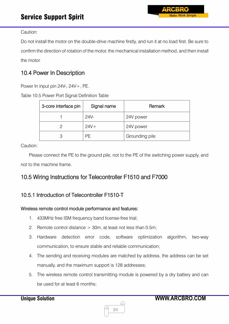
Service Support Spirit
Unique Solution WWW.ARCBRO.COM
94
Caution:
Do not install the motor on the double-drive machine firstly, and run it at no load first. Be sure to
confirm the direction of rotation of the motor, the mechanical installation method, and then install
the motor.
10.4 Power In Description
Power In input pin 24V-, 24V+, PE.
Table 10.5 Power Port Signal Definition Table
3-core interface pin Signal name Remark
1 24V- 24V power
2 24V+ 24V power
3 PE Grounding pile
Caution:
Please connect the PE to the ground pile, not to the PE of the switching power supply, and
not to the machine frame.
10.5 Wiring Instructions for Telecontroller F1510 and F7000
10.5.1 Introduction of Telecontroller F1510-T
Wireless remote control module performance and features:
1. 433MHz free ISM frequency band license-free trial;
2. Remote control distance > 30m, at least not less than 0.5m;
3. Hardware detection error code, software optimization algorithm, two-way
communication, to ensure stable and reliable communication;
4. The sending and receiving modules are matched by address, the address can be set
manually, and the maximum support is 128 addresses;
5. The wireless remote control transmitting module is powered by a dry battery and can
be used for at least 6 months;

Service Support Spirit
Unique Solution WWW.ARCBRO.COM
95
6. The receiving module is 8421 port mode or single IO mode, and up to 16 output ports.
Remote control layout
Figure 10.13 Remote Control Layout
Transmitter description:
Buttons: Start, Stop, Start (start), four directions (↑↓→←), one hand (Manual), Ignition,
Preheat, CutOxy, Plasma, Forward, Back, Close, Manual Rate, 19 buttons in total.
Pilot lamps: 3 manual speed lights (5%, 50%, 100%), 3 manual mode lights (electric, linkage,
fixed length), 1 signal indicator, 1 battery indicator (or same as signal indicator).
Instructions: When the power is turned on, the manual rate defaults to 50% light, the manual
speed is secondary state, and the manual rate is continuously pressed. The manual rate change
state machine is manual rate twice (50% light) -> manual rate three times (100%) The light is
on) -> manual rate once (5% light on) -> manual rate twice (50% light on). When starting up,
the default is to activate the manual as one state, the jog light is on, the manual change state
machine is Manual once (the jog light is on) -> Manual second (continuous light is on) ->
Manual three times (fixed light is on) - > Manual once (the jog light is on).
10.5.2 Receiver output
Model No.: Numerical control F1510-R Output port: 8
Power supply: 24 VDC.

Service Support Spirit
Unique Solution WWW.ARCBRO.COM
96
Each output port has an LED light corresponding to the state of the IO port. When it is ON, it is
on, and when it is OFF, it is off.
Remote control and F7000 series wiring instructions:
10.14 Wiring Diagram of F7000 Pin and F1510-R
10.5.3 Remote control configuration of F7000 system
After the F7000 system is started, you need to enter F4 parameter setting→F6 configuration
→F5 option→"Remote type" to "8421" in the interface, as shown in Figure 10.10.
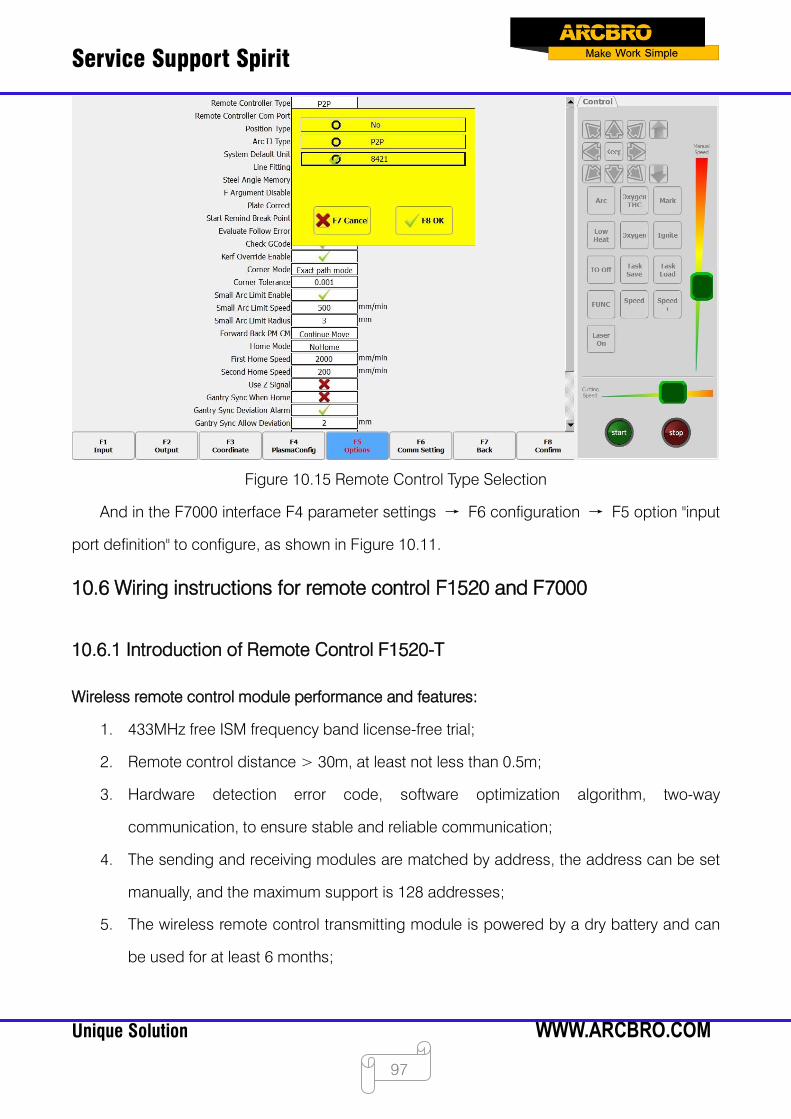
Service Support Spirit
Unique Solution WWW.ARCBRO.COM
97
Figure 10.15 Remote Control Type Selection
And in the F7000 interface F4 parameter settings → F6 configuration → F5 option "input
port definition" to configure, as shown in Figure 10.11.
10.6 Wiring instructions for remote control F1520 and F7000
10.6.1 Introduction of Remote Control F1520-T
Wireless remote control module performance and features:
1. 433MHz free ISM frequency band license-free trial;
2. Remote control distance > 30m, at least not less than 0.5m;
3. Hardware detection error code, software optimization algorithm, two-way
communication, to ensure stable and reliable communication;
4. The sending and receiving modules are matched by address, the address can be set
manually, and the maximum support is 128 addresses;
5. The wireless remote control transmitting module is powered by a dry battery and can
be used for at least 6 months;

Service Support Spirit
Unique Solution WWW.ARCBRO.COM
98
6. F1520 remote control is divided into handheld transmitter F1520-R and receiving
terminal F1520-T;
7. The receiving module F1520-R is a serial port RS232 wiring mode, which is convenient
for user wiring.
Transmitter F1520-T Description:
Figure 10.16 Remote Control Layout
Buttons: Start, Stop, Start (start), four directions (↑↓→←), one hand (Manual), Ignition,
Preheat, CutOxy, Plasma, Forward, Back, Close, Manual Rate, 19 buttons in total.
Pilot lamps: 3 manual speed lights (5%, 50%, 100%), 3 manual mode lights (electric,
linkage, fixed length), 1 signal indicator, 1 battery indicator (or same as signal indicator).
Instructions: When the power is turned on, the manual rate defaults to 50% light, the
manual speed is secondary state, and the manual rate is continuously pressed. The
manual rate change state machine is manual rate twice (50% light) -> manual rate three

Service Support Spirit
Unique Solution WWW.ARCBRO.COM
99
times (100%) The light is on) -> manual rate once (5% light on) -> manual rate twice (50%
light on). When starting up, the default is to activate the manual as one state, the jog light
is on, the manual change state machine is Manual once (the jog light is on) -> Manual
second (continuous light is on) -> Manual three times (fixed light is on) - > Manual once
(the jog light is on).
10.6.2 Receiver F1520-R wiring instructions:
The telecontroller receiver F1520-R adopts the standard serial port wiring mode and is
directly connected to the 9-pin DB connection terminal of the RS232 serial port of the system,
as shown in Figure 10.13, the serial port telecontroller receiver.
Figure 10.17 Serial Telecontroller Receiver
As shown in Figure 10.14, you can connect the RS232 back interface diagram of the serial
port, and you can plug the receiver directly.

Service Support Spirit
Unique Solution WWW.ARCBRO.COM
100
F7000 series motion controller:
Figure 10.18 Rear Interface Diagram
10.6.3 Remote control F1520 and F7000 wiring instructions:
F1520-R -RS232 F7000--RS232
Figure 10.19 F1520-R Wiring Definition Diagram

Service Support Spirit
Unique Solution WWW.ARCBRO.COM
101
Chapter 11 Code Explanation
11.1 Code Symbol and interpretation
In the cutting machine programming, the following programming symbols are generally
available, with corresponding parameter following it.
Table 11.1 Programming symbols interpretation
Programming symbols Function interpretation
N Programming segment number
G Code for ready
M Auxiliary function
X Relative coordinate or absolute coordinate of X axle
\Y Relative coordinate or absolute coordinate of Y axle
U Relative coordinate of X axle
V Relative coordinate of Y axle
I Coordinate d-value of X axle between circle center and
arc’s start
J Coordinate d-value of Y axle between circle center and
arc’s start
R Arc’s radius, when it’s positive value, the arc <180°; when
it’s negative value, the arc >180°
F Cutting rate, used for G01, G02, G03
In the following context, all the symbol “/” is the relationship of OR. For example, X/U
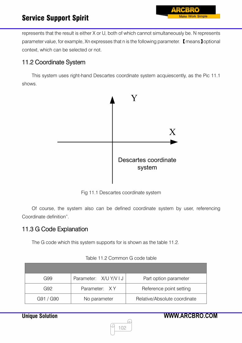
Service Support Spirit
Unique Solution WWW.ARCBRO.COM
102
represents that the result is either X or U, both of which cannot simultaneously be. N represents
parameter value, for example, Xn expresses that n is the following parameter. 【means】optional
context, which can be selected or not.
11.2 Coordinate System
This system uses right-hand Descartes coordinate system acquiescently, as the Pic 11.1
shows.
Y
X
Descartes coordinate system
Fig 11.1 Descartes coordinate system
Of course, the system also can be defined coordinate system by user, referencing
Coordinate definition”.
11.3 G Code Explanation
The G code which this system supports for is shown as the table 11.2.
Table 11.2 Common G code table
G99 Parameter: X/U Y/V I J Part option parameter
G92 Parameter: X Y Reference point setting
G91 / G90 No parameter Relative/Absolute coordinate

Service Support Spirit
Unique Solution WWW.ARCBRO.COM
103
G20 / G21 No parameter inches/metric
G41 / G42 No parameter Left/right Kerf compensation
G40 No parameter Cancel Kerf compensation
G00 Parameter: X/U Y/V straight line rapid moving tool
G01 Parameter: X/U Y/V Straight line cutting
G02 Parameter: X/U Y/V I J Clockwise arc cutting
G03 Parameter: X/U Y/V I J Anticlockwise arc cutting
1. G92 Reference point setting
Format:
G92 【Xn】【Yn】
Parameters meaning:
【Xn】【Yn】 expresses absolute coordinate of setted reference point and is also absolute
coordinate of which machine tool goes back to. If no parameter after G92, the default reference
point coordinate is (0, 0). Generally, while machine tool is taking (0,0) as reference point, this
code can be ignored.
Note:
After input this code, coordinate of reference point setted by G92 can be saved
automatically. Before new cutting code hasn’t been inputted, the coordinate of this reference
point is always available, whether system is power off or not. After input a new cutting code, if
new code has G92 instruction, the coordinate of this reference point is the context after G92, if
no G92, the reference point is default (0, 0). in one code file, G92 only appears once.
Example:
a. G92 X0 Y0
Take (0,0) as reference coordinate, when press “go back” function key, the machine tool
goes back to coordinate point (0, 0).
b. G92 X20 Y0
Take (20,0) as reference coordinate, when press “go back” function key, the machine tool
goes back to coordinate point (20,0).
2. G90/G91
Format:

Service Support Spirit
Unique Solution WWW.ARCBRO.COM
104
G90/G91
G90: absolute coordinate. X/Y in the code means absolute coordinate value; U and V mean
relative coordinate value.
G91: relative coordinate. X/Y in the code means relative coordinate value; U and V also
mean relative coordinate value.
Example:
a. G90 usage
G92 X0 Y0 // Reference point (0,0)G90 // Absolute coordinateG00 X20 Y0 // Rapidly moving tool to (20,0)M07 // Cutting device onG01 X120 Y100 //Cutting to (120,100)M08 //Cutting device offM02 // End of program (20,0)
(120,100)
Fig 10.2 G90 usage
b. G91 usage
G92 X0 Y0 // Reference point (0,0)G91 // Relative coordinateG00 X20 Y0 //Rapidly moving gun to (20,0)M07 //Cutting device onG01 X120 Y100 //Cutting to(140,100)M08 //Cutting device offM02 // End of program (20,0)
(140,100)
Fig 10.3 G91 usage
3. G20/G21
Format:
G20/G21
G20: inches unit. All of X,Y,I,J,R,U,V after G20 are inches unit.
G21: metric unit. All of X,Y,I,J,R,U,V after G21 are metric unit.
Note:
If no G20/G21 in the code, take the metric as data’s unit.
The conversion formula of inches and metric: 1 inches ≈ 25.4mm。
4. G00 Traverse rapidly
This instruction expresses that rapidly traverse to specific location, which the system will
rapidly move to at the rate of “G00 move speed* time ratio” from start point.

Service Support Spirit
Unique Solution WWW.ARCBRO.COM
105
Format:
G00 X/Un Y/Vn 【Fn】
Parameters meaning:
Fn – rapidly moving to specific location at the limited rate;
Un – displacement of endpoint’s X coordinate relative to start point of current segment,
unit(mm);
Vn – displacement of endpoint’s Y coordinate relative to start point of current segment,
unit(mm);
(in the relative coordinate system):
Xn – displacement of endpoint’s X coordinate relative to start point of current segment,
unit(mm);
Yn – displacement of endpoint’s Y coordinate relative to start point of current segment,
unit(mm);
(in the absolute coordinate system):
Xn – displacement of endpoint’s X coordinate relative to working start point, unit(mm);
Yn – displacement of endpoint’s Y coordinate relative to working start point, unit(mm);
Example:
G92 X0 Y0 // Reference point (0,0)G91 // Relative coordinateG00 X100 Y100 //rapidly moving tool to (100,100)M02
(100,100)
Fig 10.4 G00 usage
5. G01 Linear interpolation(at cut speed)
Service Support Spirit
Unique Solution WWW.ARCBRO.COM
106
This instruction expresses that linearly incise to specific location, which the system will cut
to at the rate of “incise speed* time ratio” from start point of current segment.
Format:
G01 X/Un Y/Vn 【Fn】
Parameters meaning:
The same to the meaning of G00 code, the difference of them is only that G00 expresses
linearly walking(meaning: input ports are all closed), but G01 expresses linearly incising.
6. G02 Clockwise Circular interpolation
This instruction expresses that incise clockwise arc (clockwise interpolation) to specific
location, which the system will cut to at the rate of “incise speed* time ratio” from start point of
current segment.
Format:
G02 X/Un Y/Vn in Jn 【Fn】or G02 X/Un Y/Vn R【-】n 【Fn】
Parameters meaning:
Fn – incise at limited rate;
Un – displacement of endpoint’s X coordinate relative to start point of current segment,
unit(mm);
Vn – displacement of endpoint’s Y coordinate relative to start point of current segment,
unit(mm);
in – displacement of circle centre’s X coordinate relative to start point of current segment,
unit(mm);
Jn – displacement of circle centre’s Y coordinate relative to start point of current segment,
unit(mm);
R【】-]n – the radius of arc, when the angle of arc <=180°, R is positive. Otherwise, it’s
negative, unit(mm);
(in the relative coordinate system):
Xn – displacement of endpoint’s X coordinate relative to start point of current segment,
unit(mm);
Yn – displacement of endpoint’s Y coordinate relative to start point of current segment,
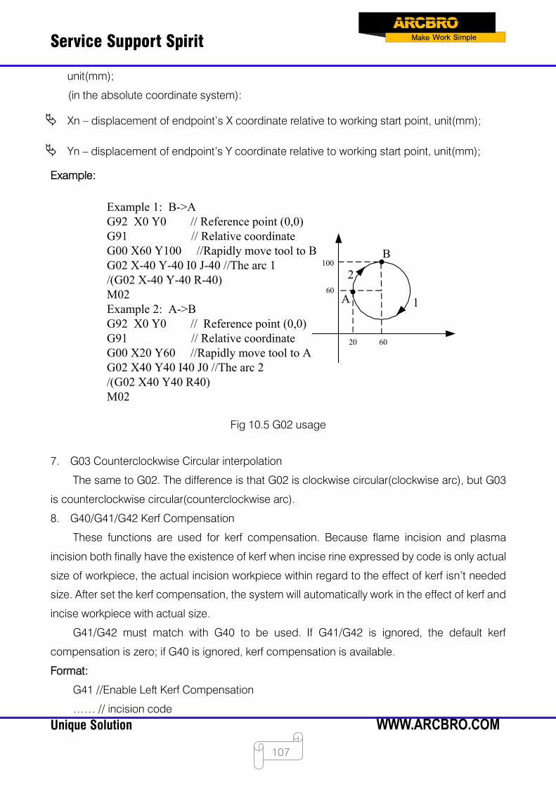
Service Support Spirit
Unique Solution WWW.ARCBRO.COM
107
unit(mm);
(in the absolute coordinate system):
Xn – displacement of endpoint’s X coordinate relative to working start point, unit(mm);
Yn – displacement of endpoint’s Y coordinate relative to working start point, unit(mm);
Example:
Example 1: B->AG92 X0 Y0 // Reference point (0,0)G91 // Relative coordinate G00 X60 Y100 //Rapidly move tool to BG02 X-40 Y-40 I0 J-40 //The arc 1/(G02 X-40 Y-40 R-40)M02Example 2: A->BG92 X0 Y0 // Reference point (0,0)G91 // Relative coordinate G00 X20 Y60 //Rapidly move tool to AG02 X40 Y40 I40 J0 //The arc 2/(G02 X40 Y40 R40)M02
A
B
1
2
60
60
20
100
Fig 10.5 G02 usage
7. G03 Counterclockwise Circular interpolation
The same to G02. The difference is that G02 is clockwise circular(clockwise arc), but G03
is counterclockwise circular(counterclockwise arc).
8. G40/G41/G42 Kerf Compensation
These functions are used for kerf compensation. Because flame incision and plasma
incision both finally have the existence of kerf when incise rine expressed by code is only actual
size of workpiece, the actual incision workpiece within regard to the effect of kerf isn’t needed
size. After set the kerf compensation, the system will automatically work in the effect of kerf and
incise workpiece with actual size.
G41/G42 must match with G40 to be used. If G41/G42 is ignored, the default kerf
compensation is zero; if G40 is ignored, kerf compensation is available.
Format:
G41 //Enable Left Kerf Compensation
…… // incision code
Service Support Spirit
Unique Solution WWW.ARCBRO.COM
108
G40 //Disable Left Kerf Compensation
G42 // Enable Right Kerf Compensation
…… // incision code
G40 // Disable Right Kerf Compensation
Example:
( Convex Roof Trapezoid w/Hole )
G21 /* metric unit */
G91 /* relative coordinate */
G99 X1 Y0 I0 J0 /*proportion factor is 1, rotate angle is 0, no mirror image*/
G00 X44.45 Y41.275 /* Rapidly moving to (44.45, 41.275)*/
G41 /* Left Kerf Compensation */
M07 /* incision beginning*/
G03 X0 Y0 I19.05 J0 /*Counterclockwise Circular interpolation */
M08 /* incision ending */
G40 /* Disable Left Kerf Compensation */
G00 X-44.45 Y-41.275 /* Rapidly moving to (-44.45, -41.275) */
G41 /* Right Kerf Compensation */
M07 /* incision beginning */
G01 X25.779438 Y58.031634 /*Linear interpolation */
G02 X75.441125 Y0 I37.720562 J-16.756634 /* Clockwise Circular incision*/
G01 X25.779438 Y-58.031634 /* Linear interpolation */
G01 X-127 Y0 /* Linear interpolation */
M08 /* incision ending */
G40 /* Disable Right Kerf Compensation */
M02 /* End of program */
Note:
The value of Kerf Compensation should be half of actual kerf width.
9. G99 proportion、rotate、image
Format:
G99 Xn Yn in Jn
Parameters meaning:
X – proportion factor, can be set from 0.001 to 1000.
Y – rotate angle, can be set from -360° to 360°.
Service Support Spirit
Unique Solution WWW.ARCBRO.COM
109
I – image of X axis, make image along X axis, 1 expresses that there is image, 0 expresses
that there is no image.
J –image of Y axis, make image along Y axis, 1 expresses that there is image, 0 expresses
that there is no image.
Note:
A code can have G99, also cannot. If there is G99, the parameter X, Y, I, J after code should
not be ignored. Mirror image and rotation will take the origin (0, 0) of Descartes coordinate as
reference point.
10. Programming notice items
The program must contain the instruction of G92 (reference point setting) and M02(end of
program).
G41/G42 must match with G40 to be used. If G41/G42 is ignored, the default kerf
compensation is zero; if G40 is ignored, kerf compensation is available.
If G20 / G21 is ignored, the system will execute G21 (metric unit).
If G90 / G91 is ignored, the system will execute G91 (relative coordinate).
M07 and M08 can’t be neglected.
When there is one parameter in the code of G00、G01、G02、G03 is ignored, if this parameter
is absolute coordinate, the system will set it G code coordinate value of last row; If it’s relative
coordinate, the system will set it 0.
G00、G01、G02、G03 can be simplified: G0、G1、G2、G3.
If there is contiguous G00 (or G01、G02、G03) around, the following G00 (or G01、G02、
G03) can be ignored.
11.4 M Code Explanation
Table 10.3 Common M code
M07 No parameters Perforation fixed cycle
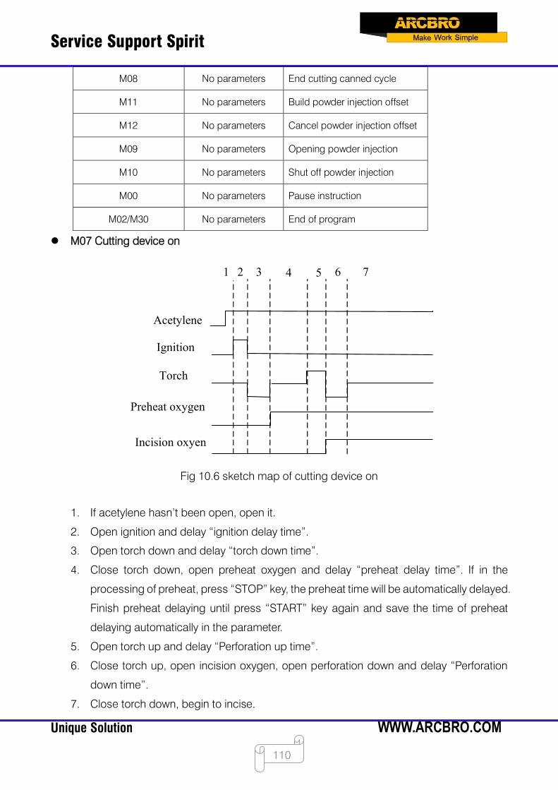
Service Support Spirit
Unique Solution WWW.ARCBRO.COM
110
M08 No parameters End cutting canned cycle
M11 No parameters Build powder injection offset
M12 No parameters Cancel powder injection offset
M09 No parameters Opening powder injection
M10 No parameters Shut off powder injection
M00 No parameters Pause instruction
M02/M30 No parameters End of program
M07 Cutting device on
Ignition
Torch
Preheat oxygen
Incision oxyen
Acetylene
1 2 3 4 5 6 7
Fig 10.6 sketch map of cutting device on
1. If acetylene hasn’t been open, open it.
2. Open ignition and delay “ignition delay time”.
3. Open torch down and delay “torch down time”.
4. Close torch down, open preheat oxygen and delay “preheat delay time”. If in the
processing of preheat, press “STOP” key, the preheat time will be automatically delayed.
Finish preheat delaying until press “START” key again and save the time of preheat
delaying automatically in the parameter.
5. Open torch up and delay “Perforation up time”.
6. Close torch up, open incision oxygen, open perforation down and delay “Perforation
down time”.
7. Close torch down, begin to incise.
Service Support Spirit
Unique Solution WWW.ARCBRO.COM
111
M08 Cutting device off
1. Close incision oxygen;
2. Open torch up and delay “Torch up time”;
3. Close torch up.
M00 End of instruction
in the processing of incision, the system will stop the machine tool with the M00 instruction,
waiting for the next operation.
M02/M03 End of program
Service Support Spirit
Unique Solution WWW.ARCBRO.COM
112
Chapter 12 Height Adjustment Device
12.1 Basic description
F2000 CNC system V1.2 version has added the function of multi-height adjustment device.
Currently supported height adjustment devices are F1650, F1627D, F1627S. This document
mainly describes the configuration of the height adjuster and the operation interface.
12.2 Mode of wiring
For details on the F1650 wiring, please refer to the "Fine Hole Cutting Installation and
Commissioning Manual".
For details on the F1627S/D wiring, see 10.5 F7000 and FCB1200PC and F1627D/S Wiring
Instructions below.
12.3 Height adjustment device configuration
To use the multi-level adjuster function, you need to configure the height adjustment device
in the program first. After the program starts, click [F4 Parameter Setting] - [F6 Configuration] -
enter the password 1396 - [F6 Communication Settings]. In the pop-up communication interface,
there are configuration options for the height adjuster.
As shown in Figure 12.1.
Figure 12.1 Height Adjustment Device Configuration
Service Support Spirit
Unique Solution WWW.ARCBRO.COM
113
Type of height adjustment device: Select the height adjustment device you want to use.
The default height adjuster model is "common", which means that the normal IO height
adjuster is used, that is, the external height adjuster is not used. This type of height
adjuster does not support the multi-tune function. Caution: F7000 software needs to be
restarted after the model of the altifier is changed.
Use THC1,2,3,4: System mount up to 4 height adjustment devices. Please check if you
want to use the height adjuster. If only one height adjuster is used, tick "Use THC1" to
turn off the other three options. If using two height adjustment devices, check "Use THC1"
and "Use THC2". And so on.
Initialize THC1,2,3,4 connections: The communication of the multi-height adjustment
device is implemented via ModBus. Each height adjustment device has a ModBus slave
address. If the slave address of height adjustment devices is the same, the
communication will not be normal. Therefore, after the height adjustment device is
connected to the system, you need to set the ModBus slave address of the height
adjustment device. The initialization button is used to implement the function of changing
the slave address.
12.4 Height adjustment device initialization connection
The height adjustment device initializes the connection process only after the height
adjuster is replaced, and it is not necessary to repeat the configuration if the height adjuster
device is unchanged.
The height adjustment device initializes the connection steps:
Enter the aligner configuration interface: Connect the actual aligner 1 to the system and
disconnect the other THC. Click the [Initialize THC1 Connection] button. A confirmation
dialog will pop up, as shown in Figure 12.2.
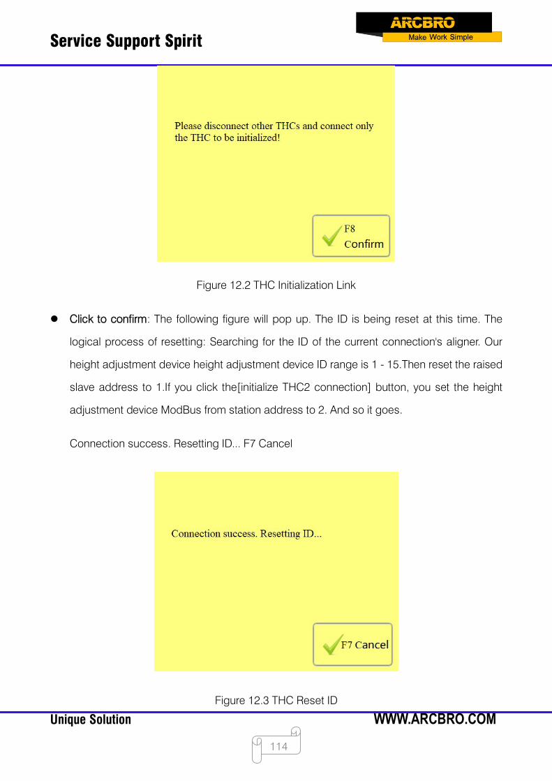
Service Support Spirit
Unique Solution WWW.ARCBRO.COM
114
Figure 12.2 THC Initialization Link
Click to confirm: The following figure will pop up. The ID is being reset at this time. The
logical process of resetting: Searching for the ID of the current connection's aligner. Our
height adjustment device height adjustment device ID range is 1 - 15.Then reset the raised
slave address to 1.If you click the[initialize THC2 connection] button, you set the height
adjustment device ModBus from station address to 2. And so it goes.
Connection success. Resetting ID... F7 Cancel
Figure 12.3 THC Reset ID

Service Support Spirit
Unique Solution WWW.ARCBRO.COM
115
After the reset is successful, the following interface will pop up.
Figure 12.4 THC Link Initialization Success
Disconnect the physical connection of the height adjustment device 1, or power off. Then
go to the height adjustment device 2 and click the [Initialize THC2] button... Repeat this process
until all the height adjustment devices to be used are initialized successfully.
12.5 Height adjustment device observation window
After the height adjustment device is configured successfully, go to the main interface,
switch the cutting mode to [Plasma], and then click the observation window switch button to
switch to the height adjustment device observation window. The height adjustment device
observation window is shown in Figure 12.5 below:
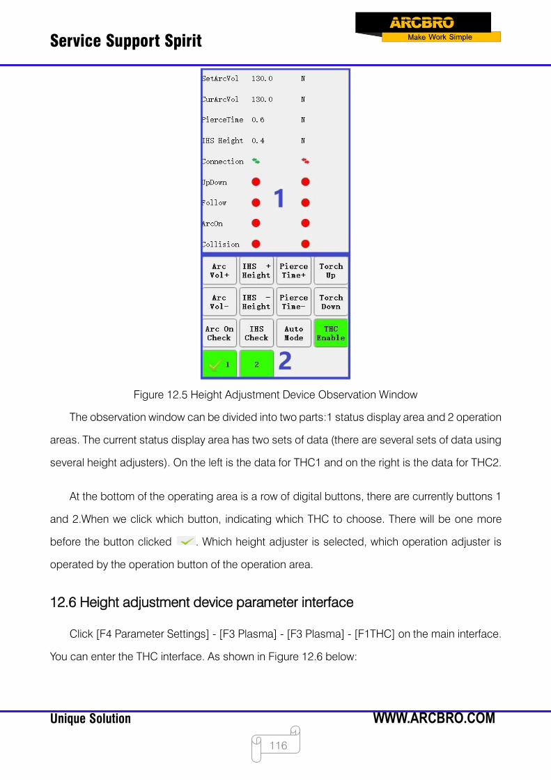
Service Support Spirit
Unique Solution WWW.ARCBRO.COM
116
Figure 12.5 Height Adjustment Device Observation Window
The observation window can be divided into two parts:1 status display area and 2 operation
areas. The current status display area has two sets of data (there are several sets of data using
several height adjusters). On the left is the data for THC1 and on the right is the data for THC2.
At the bottom of the operating area is a row of digital buttons, there are currently buttons 1
and 2.When we click which button, indicating which THC to choose. There will be one more
before the button clicked . Which height adjuster is selected, which operation adjuster is
operated by the operation button of the operation area.
12.6 Height adjustment device parameter interface
Click [F4 Parameter Settings] - [F3 Plasma] - [F3 Plasma] - [F1THC] on the main interface.
You can enter the THC interface. As shown in Figure 12.6 below:
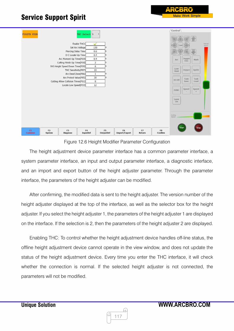
Service Support Spirit
Unique Solution WWW.ARCBRO.COM
117
Figure 12.6 Height Modifier Parameter Configuration
The height adjustment device parameter interface has a common parameter interface, a
system parameter interface, an input and output parameter interface, a diagnostic interface,
and an import and export button of the height adjuster parameter. Through the parameter
interface, the parameters of the height adjuster can be modified.
After confirming, the modified data is sent to the height adjuster. The version number of the
height adjuster displayed at the top of the interface, as well as the selector box for the height
adjuster. If you select the height adjuster 1, the parameters of the height adjuster 1 are displayed
on the interface. If the selection is 2, then the parameters of the height adjuster 2 are displayed.
Enabling THC: To control whether the height adjustment device handles off-line status, the
offline height adjustment device cannot operate in the view window, and does not update the
status of the height adjustment device. Every time you enter the THC interface, it will check
whether the connection is normal. If the selected height adjuster is not connected, the
parameters will not be modified.

Service Support Spirit
Unique Solution WWW.ARCBRO.COM
118
Chapter 13 Drilling and Cutting Integrated System
13.1 Brief introduction
The F7000 series of drilling and cutting integrated systems for cutting machines with drilling
functions. Drilling shafts are controlled in two ways: one using a motor and the other using a
cylinder. Different control methods have different parameter configurations of the system.
The configuration of the drilling and cutting integrated system is relatively simple, and only
the drilling-related parameters need to be additionally configured on the basis of the ordinary
F7000 system. Therefore, before reading this manual, users need to know about the company's
F7000 system. Refer to the company's " CNC cutting machine control system F7000" manual.
Ordinary F7000 system, if you want to upgrade to a drill-and-cut system, you need to update
the license.
13.2 Interface description
The drilling and cutting integrated system requires an additional interface. Different drill axis
control modes and different interface configurations. The basic IO configuration of the F7000
system, as well as the hardware wiring, refer to the " CNC Cutting Machine Control System
F7000" manual.
13.2.1 Motor control
The input port needs to be configured with the "Z-axis upper limit" and "Z-axis lower limit"
functions.
Figure 14.1 Motor Control Input Configuration
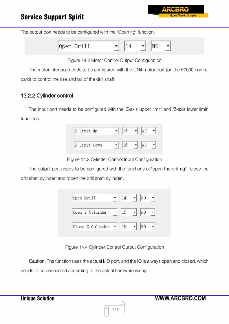
Service Support Spirit
Unique Solution WWW.ARCBRO.COM
119
The output port needs to be configured with the "Open rig" function.
Figure 14.2 Motor Control Output Configuration
The motor interface needs to be configured with the CN4 motor port (on the F7000 control
card) to control the rise and fall of the drill shaft.
13.2.2 Cylinder control
The input port needs to be configured with the "Z-axis upper limit" and "Z-axis lower limit"
functions.
Figure 14.3 Cylinder Control Input Configuration
The output port needs to be configured with the functions of "open the drill rig", "close the
drill shaft cylinder" and "open the drill shaft cylinder".
Figure 14.4 Cylinder Control Output Configuration
Caution: The function uses the actual I/ O port, and the IO is always open and closed, which
needs to be connected according to the actual hardware wiring.
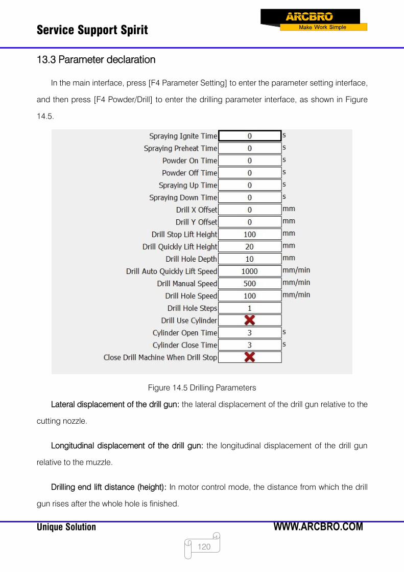
Service Support Spirit
Unique Solution WWW.ARCBRO.COM
120
13.3 Parameter declaration
In the main interface, press [F4 Parameter Setting] to enter the parameter setting interface,
and then press [F4 Powder/Drill] to enter the drilling parameter interface, as shown in Figure
14.5.
Figure 14.5 Drilling Parameters
Lateral displacement of the drill gun: the lateral displacement of the drill gun relative to the
cutting nozzle.
Longitudinal displacement of the drill gun: the longitudinal displacement of the drill gun
relative to the muzzle.
Drilling end lift distance (height): In motor control mode, the distance from which the drill
gun rises after the whole hole is finished.
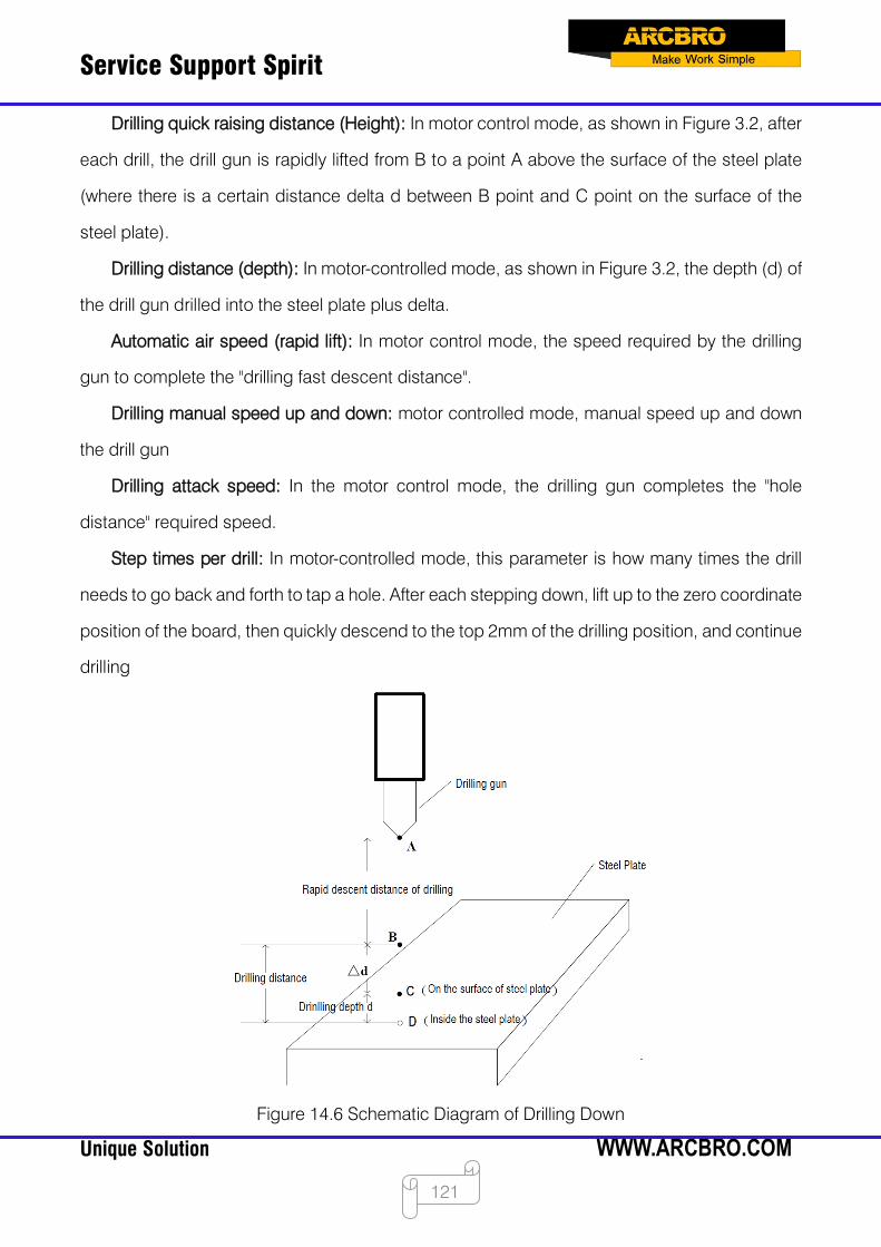
Service Support Spirit
Unique Solution WWW.ARCBRO.COM
121
Drilling quick raising distance (Height): In motor control mode, as shown in Figure 3.2, after
each drill, the drill gun is rapidly lifted from B to a point A above the surface of the steel plate
(where there is a certain distance delta d between B point and C point on the surface of the
steel plate).
Drilling distance (depth): In motor-controlled mode, as shown in Figure 3.2, the depth (d) of
the drill gun drilled into the steel plate plus delta.
Automatic air speed (rapid lift): In motor control mode, the speed required by the drilling
gun to complete the "drilling fast descent distance".
Drilling manual speed up and down: motor controlled mode, manual speed up and down
the drill gun
Drilling attack speed: In the motor control mode, the drilling gun completes the "hole
distance" required speed.
Step times per drill: In motor-controlled mode, this parameter is how many times the drill
needs to go back and forth to tap a hole. After each stepping down, lift up to the zero coordinate
position of the board, then quickly descend to the top 2mm of the drilling position, and continue
drilling
Figure 14.6 Schematic Diagram of Drilling Down
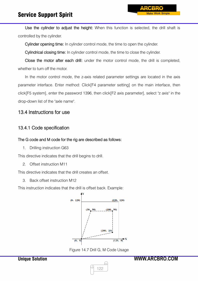
Service Support Spirit
Unique Solution WWW.ARCBRO.COM
122
Use the cylinder to adjust the height: When this function is selected, the drill shaft is
controlled by the cylinder.
Cylinder opening time: In cylinder control mode, the time to open the cylinder.
Cylindrical closing time: In cylinder control mode, the time to close the cylinder.
Close the motor after each drill: under the motor control mode, the drill is completed,
whether to turn off the motor.
In the motor control mode, the z-axis related parameter settings are located in the axis
parameter interface. Enter method: Click[F4 parameter setting] on the main interface, then
click[F5 system], enter the password 1396, then click[F2 axis parameter], select "z axis" in the
drop-down list of the "axle name".
13.4 Instructions for use
13.4.1 Code specification
The G code and M code for the rig are described as follows:
1. Drilling instruction G63
This directive indicates that the drill begins to drill.
2. Offset instruction M11
This directive indicates that the drill creates an offset.
3. Back offset instruction M12
This instruction indicates that the drill is offset back. Example:
Figure 14.7 Drill G, M Code Usage
Service Support Spirit
Unique Solution WWW.ARCBRO.COM
123
G92 X0 Y0 / / Set the reference point coordinates to (0,0)
G91 // Set relative coordinates. The parameters after X, Y appearing in the
code represent relative coordinate values.
G21 / / Set the metric unit. All X, Y, I, J, R, U, V are metric units
M11 // Build Offsets
G00 X100
Y10
//The drill gun moves quickly to the (100,10) point
G63 // Drilling holes
G00 Y80 //The drill gun moves quickly to the (100,90) point.
G63 // Drilling holes
G00 X-70 //The drill gun moves quickly to the (30,90) point
G63 // Drilling holes
G00 X-30
Y-90
//The drill gun moves quickly to the (0,0) point
M12 // Offset back
G42 // right-hand slot compensation
M07 // perforation fixed cycle
G01 X120 Y0 //Line cut to point (120,0)
G01 X0 Y120 //Line cut to point (120,120)
G01 X-120
Y0
//Line cut to point (0,120)
G01 X0
Y-120
//Line cut to point (0,0)
M08 // End Cutting Fixed Cycle
G40 // Cancel right-hand seam compensation
M02 // End of program
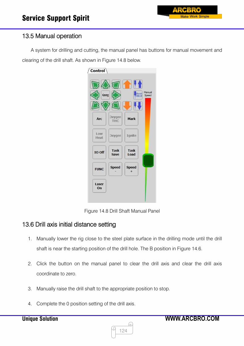
Service Support Spirit
Unique Solution WWW.ARCBRO.COM
124
13.5 Manual operation
A system for drilling and cutting, the manual panel has buttons for manual movement and
clearing of the drill shaft. As shown in Figure 14.8 below.
Figure 14.8 Drill Shaft Manual Panel
13.6 Drill axis initial distance setting
1. Manually lower the rig close to the steel plate surface in the drilling mode until the drill
shaft is near the starting position of the drill hole. The B position in Figure 14.6.
2. Click the button on the manual panel to clear the drill axis and clear the drill axis
coordinate to zero.
3. Manually raise the drill shaft to the appropriate position to stop.
4. Complete the 0 position setting of the drill axis.
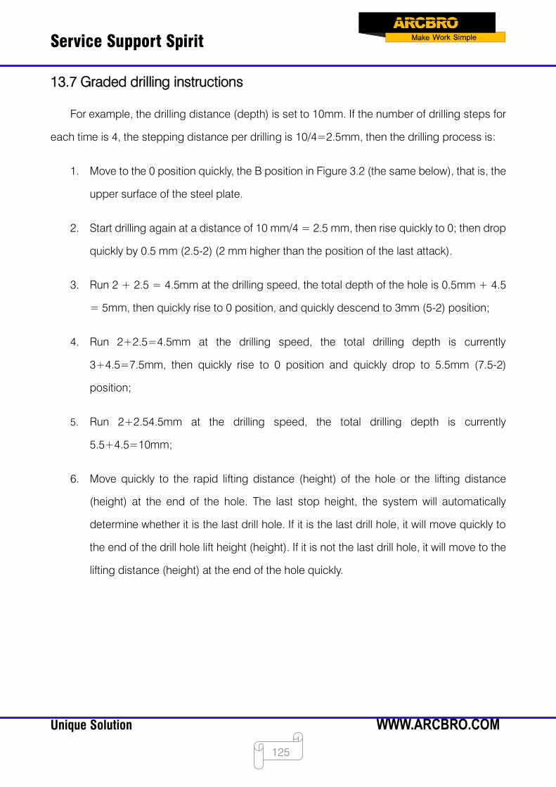
Service Support Spirit
Unique Solution WWW.ARCBRO.COM
125
13.7 Graded drilling instructions
For example, the drilling distance (depth) is set to 10mm. If the number of drilling steps for
each time is 4, the stepping distance per drilling is 10/4=2.5mm, then the drilling process is:
1. Move to the 0 position quickly, the B position in Figure 3.2 (the same below), that is, the
upper surface of the steel plate.
2. Start drilling again at a distance of 10 mm/4 = 2.5 mm, then rise quickly to 0; then drop
quickly by 0.5 mm (2.5-2) (2 mm higher than the position of the last attack).
3. Run 2 + 2.5 = 4.5mm at the drilling speed, the total depth of the hole is 0.5mm + 4.5
= 5mm, then quickly rise to 0 position, and quickly descend to 3mm (5-2) position;
4. Run 2+2.5=4.5mm at the drilling speed, the total drilling depth is currently
3+4.5=7.5mm, then quickly rise to 0 position and quickly drop to 5.5mm (7.5-2)
position;
5. Run 2+2.54.5mm at the drilling speed, the total drilling depth is currently
5.5+4.5=10mm;
6. Move quickly to the rapid lifting distance (height) of the hole or the lifting distance
(height) at the end of the hole. The last stop height, the system will automatically
determine whether it is the last drill hole. If it is the last drill hole, it will move quickly to
the end of the drill hole lift height (height). If it is not the last drill hole, it will move to the
lifting distance (height) at the end of the hole quickly.
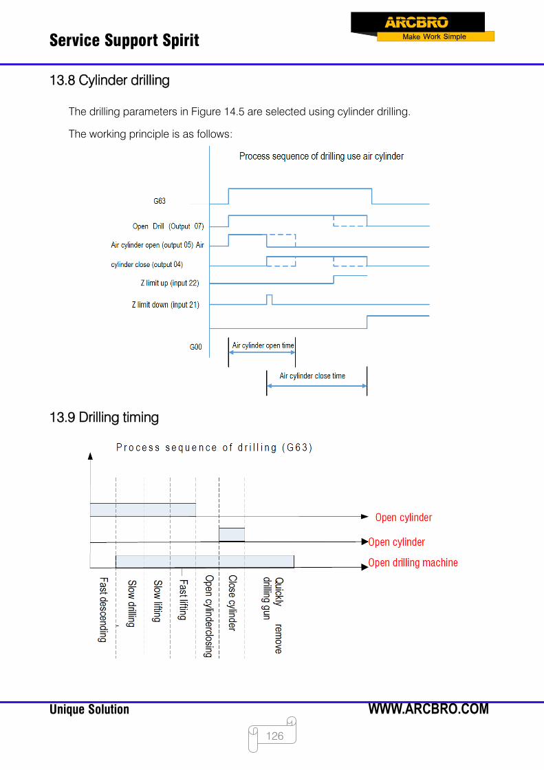
Service Support Spirit
Unique Solution WWW.ARCBRO.COM
126
13.8 Cylinder drilling
The drilling parameters in Figure 14.5 are selected using cylinder drilling.
The working principle is as follows:
13.9 Drilling timing