Embed Size (px)
Citation preview

CNC Procedure Manual and Lab Reports
Steven M. Wulf Professor John P. Sullivan
School of Aeronautics and Astronautics Purdue University
December 29, 2000

2
Table of Contents
Table of Figures .................................................................................................................. 4
Operations Reminders ........................................................................................................ 7
CNC Router..................................................................................................................... 7
CNC Jr. 4-Axis Mill ........................................................................................................ 7
Lab 1: Machining a Set of Rivet Holes ............................................................................... 9
1.1 Objectives.................................................................................................................. 9
1.2 Procedure.................................................................................................................. 9
1.2.1 Brief Description of the Experiment .................................................................. 9
1.2.2 Rivet Layout ....................................................................................................... 9
1.2.3 Tool Paths ........................................................................................................ 12
1.2.4 Verifying the Tool Paths .................................................................................. 14
1.2.5 Posting Files and Transferring Files to the CNC Jr. Computer...................... 16
Lab 2: How to create a wing using the CNC Router ........................................................ 18
2.1 Objectives................................................................................................................ 18
2.2 Procedure................................................................................................................ 18
2.2.1 Brief Description of the Experiment ................................................................ 18
2.2.2 Airfoil Input Into SurfCAM.............................................................................. 18
2.2.3 Creating the Wing ............................................................................................ 20
2.2.4 Surface Creation .............................................................................................. 24
2.2.5 Alignment Holes ............................................................................................... 26
2.2.6 Generating Tool Paths..................................................................................... 27
2.2.7 Verifying, posting, and transferring *.tap files between SurfCAM and the CNC
Machines ............................................................................................................. 34
Lab 3: How to create a mold ............................................................................................ 37
3.1 Objectives................................................................................................................ 37
3.2 Procedure................................................................................................................ 37
3.2.1 Brief Description of the Experiment ................................................................ 37
3.2.2 Notes on Input to SurfCAM.............................................................................. 37
3.2.3 Section Setup in SurfCAM................................................................................ 38

3
3.2.4 Surface Creation .............................................................................................. 41
3.2.5 Alignment Holes ............................................................................................... 42
3.2.6 Tool Path Generation ...................................................................................... 43
3.2.7 Tool Path Simulations and Mold Verification ................................................. 46
3.2.8 Finishing of the Wing Mold ............................................................................. 48
Lab 4: Creating An Axial Flow Turbine ........................................................................... 49
4.1 Objectives................................................................................................................ 49
4.2 Procedure................................................................................................................ 49
4.2.1 Brief Description of the Experiment ................................................................ 49
4.2.2 Setup of the Turbine in SurfCAM..................................................................... 49
4.2.3 Generating Tool Paths..................................................................................... 57
Procedure for Operating CNC Router Using Control Program ...................................... 59
Models created on dT Technologies CNC Router ............................................................ 62

4
Table of Figures Figure 1: Set up of axes and settings in box ..................................................................... 10
Figure 2: Single hole located at origin ............................................................................. 11
Figure 3: 4 Hole arrangement after copying locations .................................................... 12
Figure 4: Complete drilling layout ................................................................................... 13
Figure 5: Operations Manager Menu............................................................................... 14
Figure 6: Verify Menu....................................................................................................... 15
Figure 7: Stock size........................................................................................................... 15
Figure 8: Simulated tool paths in a material stock........................................................... 16
Figure 9: Clark Y airfoil inputted from ASCII file ........................................................... 19
Figure 10: Frame of wing after copying airfoil to second location ................................. 22
Figure 11: Airfoils positioned with origin at mid-span .................................................... 23
Figure 12: Surface created between two airfoil cross sections ........................................ 24
Figure 13: Detail of arrow at rear of wing surface.......................................................... 25
Figure 14: Alignment holes in place................................................................................. 27
Figure 15: Tool information screen.................................................................................. 28
Figure 16: Tool paths for the alignment holes ................................................................. 29
Figure 17: Tool path for top surface of wing ................................................................... 31
Figure 18: Operations manager screen............................................................................ 32
Figure 19: Final tool paths on wing ................................................................................. 33
Figure 20: Wing ready for simulation, with SurfCAM verify toolbar in upper right hand
corner ........................................................................................................................ 35
Figure 21: Simulation of wing being cut .......................................................................... 36
Figure 22: Airfoil input for lower surface mold ............................................................... 39
Figure 23: Airfoil ready for mold development ................................................................ 40
Figure 24: Mold progress after copying airfoil section ................................................... 41
Figure 25: Mold Surface................................................................................................... 42
Figure 26: Alignment hole placement on mold................................................................. 43
Figure 27: Span wise tool paths of the mold .................................................................... 44
Figure 28: Alignment hole tool paths ............................................................................... 46
Figure 29: Setup of material stock.................................................................................... 47

5
Figure 30: Simulated mold cuts using SurfCAM verify.................................................... 48
Figure 31: Airfoil input for Turbine ................................................................................. 50
Figure 32: Rotated Airfoil ................................................................................................ 51
Figure 33: Turbine hub and airfoil................................................................................... 52
Figure 34: Turbine with hub surrounded with surfaces ................................................... 53
Figure 35: Hub with one blade extruded.......................................................................... 54
Figure 36: New blade position, from the top view of the turbine..................................... 55
Figure 37: Turbine with arrayed blades........................................................................... 56
Figure 38: Rendered turbine............................................................................................. 56

6
Safety Procedures for CNC Machinery
Revised 06-26-00 1. The CNC machines are NOT to be operated by any individual without approval,
proper training, and knowledge of the machine and the software that controls the machine. See Prof. Sullivan, Don Bower, or the Teaching Assistant for training and approval to operate machines.
2. Safety glasses, available in the CNC Lab Area, are required to be worn at all times of operation of the CNC machines. Hearing protection is available, and it is highly recommended that it be used during machine operations.
3. Keep all appendages from any part of the moving machinery at all times. While the motor is running on any of the CNC machines, do not place hands or fingers near cutting area. Long hair has the potential of being caught in the motor or spindle; make sure hair is secured back in place before operating the devices.
4. Do NOT operate the machine tools alone. You must have another person in the area when operating the machine.
5. In case of emergency, a phone is available near the Zero G test tower, beside the Boeing Wind Tunnel. Call 911 in case of emergency.

7
Operations Reminders
1. Know and understand the properties of both the material you are cutting, and the tool you are cutting with. High Speed Stainless and Carbide tools have different strengths and useful speeds.
2. Know the axis for the particular machine being used. The motion of the bit direction reverses when moving from a stationary table (the CNC Router) to a moving table (CNC Jr.).
CNC Router
1. Routinely clean cutting table, and the gears of the track that the machine runs on.
Debris that is compacted in the teeth of the gears can cause unsteady motion of the machine, leading to poor performance.
2. Always have safety shields in place during operation of the CNC Router. This prevents flying debris from hitting any operators of the machine.
3. Make sure to have direct access to an emergency stop button. There are two accessible emergency shutoff buttons, both located near the computer terminal. This button will stop the travel of the router; however, this will not stop the spindle from rotating. This must be done using the ON/OFF switch on the router motor.
CNC Jr. 4-Axis Mill
1. When machine is not in use, unplug the cord labeled ‘OIL’. This stops the
operation of the oil pump circulating. Extended use of the pump with empty the reservoir needed to lubricate the table. Also unplug the cord that drives the motors. These stepping motors can become overheated, even when not in use.
2. Make sure any material is secure in the rotating 4th axis plate. Attaching the material is possible using the pass through axial plug, or the T-Bolts found in the workbench.

8
Lab possibilities for Spring 2000 AAE490 Design, Build, Test Class Written By Steven Wulf, For Dr. Sullivan
1.) Machine a random array of rivet holes. Machine the same pattern into two different plates, and have the riveted together by the Aviation Technology department. Uses these two plates to test the different configurations of rivet placement by loading them in tension until failure.
2.) Construct a simple wing design, using a single airfoil element. This will be the first step into the realm of 3-D design in SurfCAM and on the CNC router. A simple straight wing that can fit within a 2” thick piece of foam will be a simple and inexpensive way to show the usefulness of the machine. Limit airfoil choice to a thin NACA airfoil, with a maximum chord of 4-5”, and a thickness not to exceed the 2” of the material.
3.) Axial flow turbine blade design and machining. This section of the labs will introduce 4-Axis design and machining, using the CNC Jr. machine. These files will have to be fully tested before their use, as the 4-Axis machining is not well tested yet. Keeping these turbine sections small will help with time, and using small blocks of wood will keep cost down. The maximum radius of the cascade would have to be around 3 to 3.5”, as this is the maximum the CNC Jr. can handle in the current configuration.
A simple lab report format follows:
9
Lab 1: Machining a Set of Rivet Holes
1.1 Objectives
1.) Introduce the CNC Jr. Milling machine. 2.) Create a random set of rivet holes to machine into two metal plates 3.) Have these plates riveted together; test plates for failure mode and record path
of crack on material
1.2 Procedure 1.2.1 Brief Description of the Experiment
This lab will introduce the CNC Jr. milling machine, which is capable of up to 4Axes of motion, and will use it to machine a set of four rivet holes. An analysis of the rivet hole location is being conducted to learn about the propagation of cracks in materials as they are stressed, as an aircraft skin would be. Some rivet layouts will cause the skin to fail quickly, while others will be considered ‘optimal’, and will not fail until a much higher load is applied.
1.2.2 Rivet Layout
Although the layout of rivet holes in aircraft is not arbitrary, for the purposes of this lab, the layout is such. All that is required is the layout of 4 holes that will be used to rivet plates together. The following procedures will produce plates with rivet holes.
1.) Open SurfCAM. 2.) Change the VIEW of the workspace by clicking on the word VIEW in the
lower left hand corner. Change the value to 7 – ISOMETRIC. 3.) Set the coordinate system for the drawing to VIEW. This uses the small set of
yellow coordinate axes to reference all cuts and movements, instead of the world set of coordinated. Again, do this by clicking on the word COORD in the lower left hand corner, and toggling between VIEW and WRD.
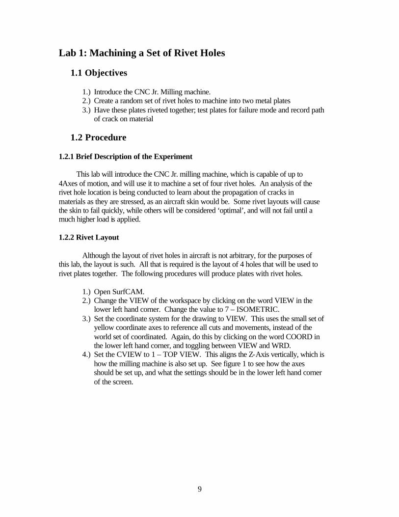
4.) Set the CVIEW to 1 – TOP VIEW. This aligns the Z-Axis vertically, which is how the milling machine is also set up. See figure 1 to see how the axes should be set up, and what the settings should be in the lower left hand corner of the screen.

10
Figure 1: Set up of axes and settings in box
5.) Press the MAIN button to return to the main menu of SurfCAM. Once here, click the CREATE button. This will bring up another menu of different objects that can be created in SurfCAM. Select CIRCLE.
6.) Another menu comes up asking about the properties of the circle to be created. Click CENTER/DIA. At the prompt for the diameter of the circle, enter 0.125. This will create a 1/8th inch hole for the rivets.
7.) At the prompt to select the center point of the circle, click KEYBOARD. This will allow the entering of the desired coordinates for the hole. Make sure the
center is at the origin, and click ok. Press the (called the Zoom button from here on). The SurfCAM screen will look like figure 2. The radius of the hole is indeed 0.125 inches, although it appears larger.

11
Figure 2: Single hole located at origin
8.) Return to the main menu of SurfCAM. Click on the TRANSFORM button. 9.) Make sure the COPY button is highlighted on the menu bar. Click the
ROTATE button. This will be used to rotate the hole around a set point, making an array of hole for the rivets.
10.) SurfCAM prompts for the item to rotate. Either click directly on the circle on the screen, or press VISIBLE on the menu.
11.) Enter 90 for the angle for SurfCAM to rotate through at the prompt that comes up. Click ACCEPT.
12.) When prompted to ‘Select the point of rotation’, press the KEYBOARD button on the menu. Enter the following values in the boxes that appear:
X 0 Y 0.5 Z 0
Enter 3 for the number of copies to be made, and leave all other settings as they are at the prompt. This will create an arrangement of 4 holes in the shape of a diamond (from the top view). Click the Zoom button, and the SurfCAM screen should resemble figure 3.

12
Figure 3: 4 Hole arrangement after copying locations
1.2.3 Tool Paths After the layout of the holes is established, it is time to drill the pattern into two
different plates. The following section will setup the tool paths in SurfCAM. 1.) From the SurfCAM main menu, click NC. This will open the numerically
controlled tool path generation section of SurfCAM. 2.) Make sure the NC MODE is set to 2-Axis. Click the NC MODE button on
the NC menu; click 2-AXIS on the menu that comes up. 3.) Select DRILL from the menu to start the process of making the rivet holes.
This will bring up the 2Axis Drill properties page. The following items will need to be changed on the Tool Information tab for the drill process:
Tool (click on the numbered button to the right of the drill size to change) 1/8 HSS Drill ( Number 16)
Spindle Speed 1790 CW Feed Rate 6 IPM

13
4.) Switch to the Drill Control tab. The main setting to change here is the Hole Depth. Assuming the material is 1/8th inch thick aluminum plate, the hole depth must be at least 0.125 inches. In the Box next to the hole depth, enter 0.200.
5.) Click OK. 6.) SurfCAM then prompts: ‘Select points and/or circles for drilling and then
‘Done’’. BEFORE clicking any of the circles on the screen, click the
button. Make sure that it says ON, instead of OFF. This will allow all of the items on the screen to be selected before the tool path is made. Click on each of the circles on the screen. Each one should turn red once it is selected. Click DONE once all of the circles are highlighted.
7.) SurfCAM prompts: ‘Select the start point of the drill cycle.’ Click CENTER on the menu on the left side of the screen, then click on any one of the holes. White lines denoting the path of the bit will appear on the screen. Click DONE.
8.) SurfCAM prompts: ‘Select a new drilling tool or done to end the operation.’ If a second drill bit were being used, this would be the place to specify it. For the purposes here, simply click DONE to end the operation.
9.) ACCEPT the tool path. Figure 4 shows how SurfCAM will appear after the
tool path has been accepted, and the (Zoom out) button has been pressed twice.
Figure 4: Complete drilling layout

14
1.2.4 Verifying the Tool Paths
Once all of the setup has been done for the rivet holes, it is time to simulate the procedure in SurfCAM. SurfCAM has a built in 3-D solid simulation engine, capable of showing all of the tool paths created. Follow this procedure to verify the tool paths in SurfCAM.
1.) From any screen in SurfCAM, press the Operations Manager button on the top toolbar. This will bring up a menu, and the SurfCAM screen should look like figure 5.
Figure 5: Operations Manager Menu
2.) Once the Operations Manager screen is open, all of the tool paths that have been created can be seen listed in the center window. In the case of the rivets, there is only one set of holes to drill, so only one tool path is needed. This is labeled as the 2Axis Drill: Drill- file in the center window. Highlight this tool path (if it is not already) by clicking on it once.
3.) Click on the (verify button) in the top menu. Another menu will appear at the upper right of the screen. See figure 6 for a visual of this menu.

15
Figure 6: Verify Menu
4.) Before the simulation can be done of the tool paths that have been created, a model of the material must be established around the holes that have been created. To do this, click MODEL on the toolbar, STOCK at the pull down, and select BOX.
5.) A menu, as seen in figure 7, will appear. Fill in the numbers as seen in figure 7. If these are not readable, use the following table to establish these dimensions:
Corner 1 X = -1.0 Y = -1.0 Z = -0.125 Corner 2 X = 1.0 Y = 6.0 Z = 0.0
Figure 7: Stock size
6.) Press the Zoom all key again, so the screen shows the full outline of the simulated material. At this time, the tool paths can be simulated. Press the
(simulation button) on the toolbar. The material specified on the screen will appear to become solid, and the tool paths can now be simulated by pressing the play button on the toolbar. The actual drilling of the holes will be quick. The final result of the simulation will appear like figure 8.

16
Figure 8: Simulated tool paths in a material stock
7.) Close the verify section, and the original hole arrangement and tool paths will be displayed.
1.2.5 Posting Files and Transferring Files to the CNC Jr. Computer
After all of the tool paths have been verified, it is time to post the files in G-Code, and transfer the information to the computers that control the machines.
1.) Re-enter the Operations Manager Screen of SurfCAM (refer to earlier sections
to remember how to do this). 2.) Highlight the operation to be sent to the control computer. In the case of the
rivet holes, the tool path will be the 2Axis Drill cycle located under Setup 1. 3.) Make sure ‘CNC Router” is highlighted in the right window, and click POST
at the bottom of the Operations Manager window. a short time will pass as SurfCAM calculates the coordinates and commands, known as G-Code, that will be needed to accurately control the machine. Finally, a screen full of coordinates will appear.
4.) Save this file in the aae490dbt/Lab1/yourgroup directory. Make sure the file has a name that makes sense, and make sure it has a *.tap extension. The control programs will not recognize the file without the *.tap extension.

17
5.) Transfer the file to a floppy disk, and take it over to the CNC Jr. control computer to be uploaded and machined.

18
Lab 2: How to create a wing using the CNC Router
2.1 Objectives
1.) Learn about file input into SurfCAM, including the use of ASCII files for airfoil points
2.) Create, in SurfCAM, a simple wing planform using the inputted airfoil point file
3.) Create a tool path representative of the surface of the created wing 4.) Transfer the machining files to the CNC router, and than use these files to cut
the wing shape.
2.2 Procedure 2.2.1 Brief Description of the Experiment
The focus of this experiment will be to design a simple wing within SurfCAM,
starting with a Clark Y airfoil file provided to you. This wing will be created using the basic features of SurfCAM, along with the 2 and 3-Axes NC Modes inside of the program. Once the wing is designed, it will be machined on the CNC router. 2.2.2 Airfoil Input Into SurfCAM The process of developing and machining a wing using the CNC router and SurfCAM is fairly straightforward and simple. There are several programs available from different sources to design airfoils. Sources such as the UIUC airfoil database have listings for hundreds of different airfoils already in file form, containing points. Although the files are in a *.dat format, which SurfCAM does not accept, they are easily changed to a SurfCAM friendly *.asc format. This has turned out to be one of the best ways to get airfoils into SurfCAM for machining wings. The following procedure should be followed to get ASCII data files into SurfCAM:
1.) Open SurfCAM 2.) On the main menu on the left hand side of the screen, click on the button
FILES 3.) Click OPEN 4.) A windows file screen should pop up. Under the file name box, go to the
extension pull down menu, and switch to the ASCII extension, *.asc. ASCII files should now be available. If you change the directory before you change the file type, the file directory automatically returns to the default folder under SurfCAM.
5.) Select the file named ‘clarky1.asc’, located in the C:\aae490dbt\lab3 directory, and click open. This is a common airfoil in remote control gliders.

19
6.) SurfCAM will give you the option to open the data as several different formats. Select e.) Splines for best the results when opening only a single airfoil.
7.) Click O.K. A screen telling you whether the file conversion from ASCII to SurfCAM usable information was successful or not. Close this screen. The outline should be on the screen with the leading edge at the origin.
8.) Click the VIEW button at the lower left of the screen, and switch to 7.) Isometric View.
9.) Return to the main Menu of SurfCAM by pressing the MAIN button in the left side of the screen. There should be a complete airfoil section in the display, just like figure 9.
Figure 9: Clark Y airfoil inputted from ASCII file
Once the initial airfoil is inputted to SurfCAM, it is easy to manipulate the section in any way. This includes rotating the section, scaling it, and copying it to different locations. These features fall into the next section of the manual, the creation of a simple wing planform design in SurfCAM.

20
2.2.3 Creating the Wing After inputting an airfoil into SurfCAM, it is necessary to go through a couple steps in order to make sure the section is ready to be used in a wing design. The first required step is to make sure the wing is in the right plane for the eventual machining process in the CNC router. The CNC router has a fixed coordinate system associated with it. The X-axis of the table runs from left to right along the table. The Y-axis runs from the front of the machine to the rear of the machine. The Z-axis is the axis where the router moves the drill bit up and down, creating the contours of a surface such as an airfoil. In order to coordinate the axis in SurfCAM with those inside the router control program, it is necessary to change three features in SurfCAM. The first is to change to view of the object. As the program opens, there is an arbitrary coordinate system placed at the nose of the airfoil (0,0,0). To get this to the appropriate, Z-axis vertical orientation, follow this procedure:
1.) Click on the VIEW button in the lower left-hand side of the screen. 2.) Click 1.) TOP VIEW, to get the axis oriented. The Z-axis should now be
pointing toward the top of the screen.
The second feature to change in SurfCAM is exactly how the program is going to see to machine the object. To get this oriented correctly, press the following keys:
1.) Click on the CVIEW button in the lower left-hand corner. 2.) Choose option 1.) TOP VIEW to get this oriented correctly. This tells
SurfCAM and the router that the CVIEW (Construction View) is coming down onto the upper surface of the airfoil.
The final feature to change at this time is which coordinate system SurfCAM will
base its operations on. Currently, as the airfoil sits on the desktop, there are two different coordinate systems at work (although there may appear to be only one). The first coordinate system is the WRD (world) system. This system always has the Z-axis pointing up. This may be fine for some features, but as can be seen later, this will not work for airfoils. The second coordinate system on the desktop is the Construction View coordinate system, or VIEW. The airfoil nose is currently placed on this system. This allows SurfCAM to machine other surfaces of an object, according to which view CVIEW is set on. This feature will be seen as the wing takes shape, and is ready to be machined later. To change the coordinate system that SurfCAM is using, click on the COORD button in the lower left-hand corner of the screen. Clicking here should toggle either WRD or VIEW to be displayed. For the airfoil, make sure to put COORD equal to VIEW.
Once the correct coordinate systems have been established in SurfCAM, the screen should consist of a 2-D airfoil sitting in the y-z plane. Once the airfoil is positioned correctly in SurfCAM, it is time to create the surface of the wing itself. To do this, a few steps are required:
21
1.) Make sure the main menu is up on the left side of the screen. Click TRANSFORM. The menu that is brought up should contain several different options, including SCALE, LOCATION, and ROTATE. There should also be two other buttons toward the middle of this menu, labeled COPY and MOVE. These buttons refer to the object that is being worked on. If COPY is highlighted, the object will be copied to a new location. This will mean that two of the exact same objects will be on the display – one where the object originally was, and one in the new location. MOVE, however, takes the object on the desktop, and places it in whatever new location is specified. Either button may be used to the same effect, however, if it is set incorrectly, it may take some time to restore an original image if something went wrong in the process. For now, change the menu to read MOVE.
2.) It is necessary to scale the 2-D airfoil to a certain dimension before it is manipulated further. Depending on the method of input for the original airfoil file, the length from leading edge to trailing edge may vary. If the ASCII program mentioned earlier is used, the chord length of the airfoil is outputted to be one. To change this to a desired chord length, click SCALE in the TRANSFORM menu.
3.) Click VISIBLE to highlight the airfoil on the display. Click DONE on the display.
4.) A window asking for a scale factor should come up. Enter ‘5’ to increase the size of the airfoil to 5 inches. SurfCAM also prompts for a ‘point to scale about’. Click KEYBOARD, and enter zero for each X, Y, and Z.
5.) As long as MOVE is selected in the TRANSFORM menu, the original airfoil will be deleted, and the appropriately sized airfoil will appear.
6.) Press the BACKUP button to return to the TRANSFORM menu. 7.) Change the menu to read COPY. Click LOCATION. 8.) A screen will come up asking which item to change the location of. Click
VISIBLE to select the airfoil on the screen. Again, as SurfCAM prompts for a ‘location to move from’, click KEYBOARD on the menu, and enter the origin.
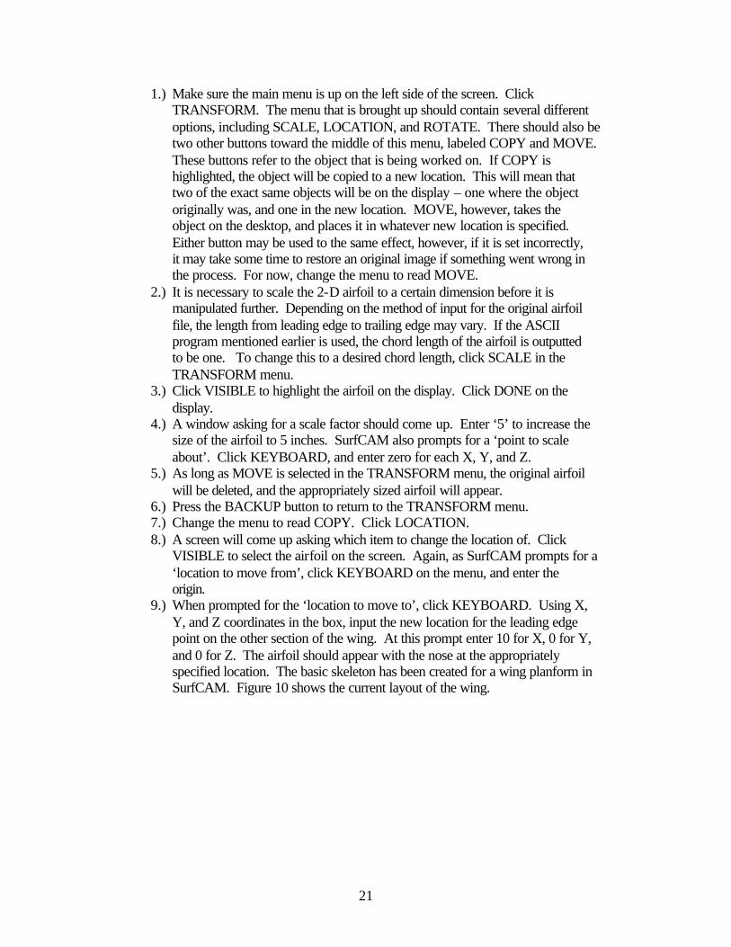
9.) When prompted for the ‘location to move to’, click KEYBOARD. Using X, Y, and Z coordinates in the box, input the new location for the leading edge point on the other section of the wing. At this prompt enter 10 for X, 0 for Y, and 0 for Z. The airfoil should appear with the nose at the appropriately specified location. The basic skeleton has been created for a wing planform in SurfCAM. Figure 10 shows the current layout of the wing.
22
Figure 10: Frame of wing after copying airfoil to second location
For alignment later, it will be necessary to shift the location of the entire wing so the origin is exactly half way between the tips. Follow this procedure to accomplish this:
1.) On the TRANSFORM menu, making sure that MOVE is highlighted instead
of COPY, press the DISTANCE button. 2.) Click on VISIBLE to choose both airfoils. Click DONE. 3.) A prompt comes up asking the distance to translate the items. Enter ‘-5’ for X,
while making sure Y and Z are both zero. 4.) The airfoils will translate left 5 inches, making the origin of the drawing mid-
span of the wing. Your screen should now look like figure 11.

23
Figure 11: Airfoils positioned with origin at mid-span

24
2.2.4 Surface Creation After the airfoils are placed in SurfCAM, it is time to actually create the surface that will be machined. The following procedure can be used to create this surface.
1.) Return to the main menu. Click CREATE to begin forming the wing. 2.) Click SURFACE. Since the wing will be created from two different airfoils,
select CROSS SECT, and then SECTIONS. This will get you to the point of making the wing fro the two airfoils on the screen.
3.) At this point, SurfCAM prompts for the selection of different cross sections to make the surface out of. Click on the two airfoils placed earlier. Click DONE. A surface should appear between the two cross sections. Check the surface to make sure it appears correct in relation to the airfoils created earlier. Refer to figure 12 for how the wing should look.
Figure 12: Surface created between two airfoil cross sections

25
4.) Use the (zoom window key) located on the top toolbar to examine the yellow arrow that represents the surface. Press the zoom button, and surround the arrow on the rear of the wing. See figure 13 for the zoomed in view of the arrow.
Figure 13: Detail of arrow at rear of wing surface
5.) Make sure that the stem of the arrow is pointing toward the outside of the surface. The position of the arrow is correctly depicted in Figure 12 above. This provides information to the router as to which side of the surface to machine – the inside or the outside. If it appears that the arrow is pointing toward the inside of the surface or the airfoil, this can be easily changed using the following procedure: a.) Return to the main menu. b.) Click EDIT, then click SURFACE. c.) Click on SIDE, and then click on the arrow at the surface. It will flip from
the inside of the surface to the outside. The surface should be ready to make tool paths on. However, since the wing is a two sided object, there must be a way to machine both sides. It could be done with a 4-Axis machine, where the router table could flip completely over. Instead, the object must be flipped during the machining, so both surfaces are cut. This is accomplished through two

26
alignment holes drilled in material, with pegs holding the item straight. The next section of the lab will deal with the setup to flip the wing during machining. 2.2.5 Alignment Holes In order to cut the bottom of the wing, there must be at least two reference holes to line up when flipping.
1.) From the main menu, click CREATE. For the alignment holes, it will be necessary to use a CIRCLE representation on the surface.
2.) Click CENTER/DIA to draw the hole. A prompt will come up for the diameter of the hole to create. Enter 0.5.
3.) When SurfCAM prompts to enter a location for the holes, use the KEYBOARD button. Enter the following coordinates for the center of the hole:
X 0 Y -1 Z 1
This will place the first hole an inch in front of and above the leading edge of the wing.
4.) SurfCAM will place a circle on the screen representing the top of the hole that will be used for the alignment pins. SurfCAM will be prompting for the center location of another hole at this point. Click KEYBOARD again, and enter the following points:
X 0 Y 6 Z 1
This will place another circle one inch behind and above the trailing edge. Figure
14 shows the proper hole locations.

27
Figure 14: Alignment holes in place
2.2.6 Generating Tool Paths
Since the wing that is being made is two sided, the alignment holes, created in the file as circles, should be machined first.
1.) Return to the main menu. Make sure the CVIEW is on TOP view, and the
COORD is on VIEW. 2.) From the main menu, click NC. Change the NC MODE to 2-AXIS. 3.) Select POCKET, and then select SINGLE. SurfCAM is now prompting to
‘Select beginning elements’. Click on one of the two circles (order doesn’t matter here), then the other.

28
4.) Click DONE on the menu to the left. A menu comes up asking for information about the 2 Axis Pocket process. Under the ‘Tool Information’ tab, enter the following information:
Tool ¼” HSS End
Spindle Speed 10000 Feed Rate 65 Plunge Rate 35
To enter the tool information, click on the numbered button next to the tool
description on the ‘Tool Information’ screen. The tool info screen, as seen in Figure 15, will be where the actual tool is specified.
Figure 15: Tool information screen
To select the correct tool here, make sure the tool shape is selected as an end
mill: . This will allow the correct tools to be displayed in the left window. Here, select tool #32: ¼ Inch HSS End.
29
5.) Click on the ‘Cut Control’ tab. Enter the following values (do not change any other settings on this menu, besides these):
Cutting Method Climb
Pocket Cut Mode Spiral Amount to Remove In Z 2.5
Plunge Type Plunge Once this information is entered, press APPLY, then OK. A tool path will appear
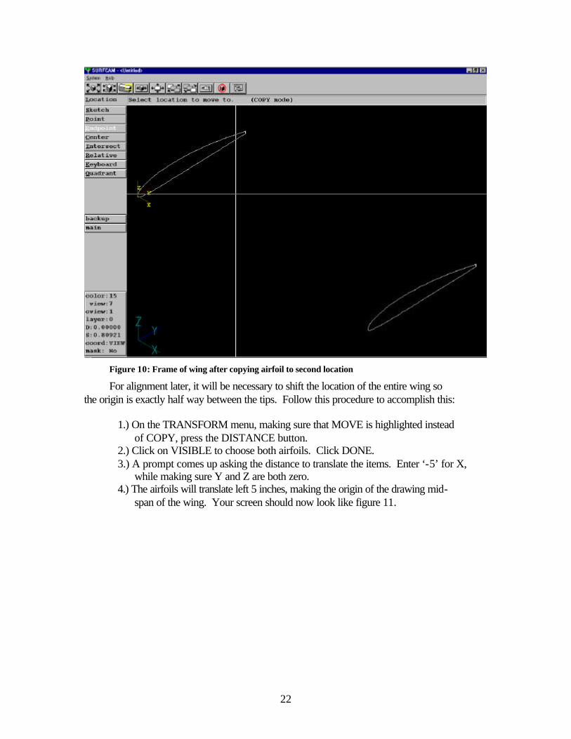
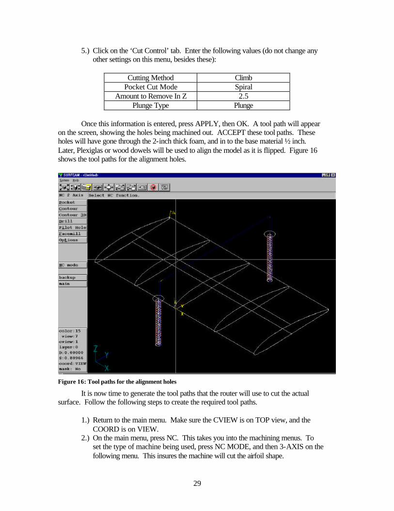
on the screen, showing the holes being machined out. ACCEPT these tool paths. These holes will have gone through the 2-inch thick foam, and in to the base material ½ inch. Later, Plexiglas or wood dowels will be used to align the model as it is flipped. Figure 16 shows the tool paths for the alignment holes.
Figure 16: Tool paths for the alignment holes
It is now time to generate the tool paths that the router will use to cut the actual surface. Follow the following steps to create the required tool paths.
1.) Return to the main menu. Make sure the CVIEW is on TOP view, and the
COORD is on VIEW. 2.) On the main menu, press NC. This takes you into the machining menus. To
set the type of machine being used, press NC MODE, and then 3-AXIS on the following menu. This insures the machine will cut the airfoil shape.

30
3.) Press PLANAR to begin the tool path creation. SurfCAM will prompt: ‘Select surfaces to cut across’. Simply click on the yellow arrow that defines the surface. Another menu will come up that will be used to define the feeds and speeds of the router, the bit you are using, the material you are cutting, and how you want the surface cut.
4.) This lab will use blue foam for the machining of the wings. The following is a table of values to enter in the respective boxes on the ‘Tool Information’ screen. No other information should be changed on the ‘Tool Information’ tab, or the ‘Cut Control’ tab.
Tool (select ballnose with the
button) ½ HSS Ballnose
Spindle Speed 10000 Feed Rate 125
Plunge Rate 65
5.) Switch to the ‘Cut Control’ tab to adjust some of the other settings in SurfCAM. Use the following table to adjust the appropriate settings.
Rapid Plane 2.0 Step Type Scallop Step Size 0.005
6.) Press APPLY, then OK. This will return you to the main screen of SurfCAM,
with a prompt saying ‘Select point to begin’. This is the place where the actual bit will travel to first.
7.) With ENDPOINT highlighted in the menu to the left, click on either of the corners of the trailing edge. A yellow box should appear around the endpoint closest to the mouse click.
8.) SurfCAM then prompts: ‘Select point in direction of cut’. This reference point defines the direction of the tool bit across the object to be cut. Click on the leading edge of the wing, along the same side that the trailing edge was chosen. Another yellow box will appear.
9.) Finally, SurfCAM prompts: ‘Select offset side’. Click anywhere on the surface being machined. This reference point defines the direction the progressing tool paths will cover.
10.) After a very brief processing time, a tool path will begin to appear on the screen, over the surface you defined. At the end of this tool path, you will be asked if you would like to accept or reject the path. Choose ACCEPT. This completes the tool path generation for the upper surface of the wing. Figure 17 shows the tool path for the top of the wing (note: tool paths for the alignment holes have been hidden to allow full view of the surface cuts.

31
Figure 17: Tool path for top surface of wing
After the tool paths have been generated for the upper surface, it is necessary to generate the paths for the bottom surface. It may be difficult to create these paths with the upper paths in place on the screen, however. Follow this procedure to get the wing ready for the lower surface tool paths:
1.) Return to the main menu of SurfCAM. On the tool bar, press the operations
manager button, . This will open the tool path screen. Refer to figure 18.

32
Figure 18: Operations manager screen
2.) Highlight the 3Axis Planar tool path in the window by clicking on it once.
This tool path can be removed from the display by clicking the hide path button. On the main screen, the tool path should have been removed.
3.) Click DONE to return to the SurfCAM main menu. 4.) Click the CVIEW button at the lower left of the screen. Change the CVIEW
from 1.) Top View to 4.) Bottom View. This produces the effect of flipping the item over in SurfCAM, so the lower surface of the airfoil can be machined. Also, make sure VIEW is selected on the COORD button.
5.) For a better view, click the VIEW button and select 8.) Axonometric View. This allows a good view of the lower surface of the wing to make the tool paths on.
6.) From this point, the same procedure will be used to generate the tool paths on the lower surface of the wing as were used on the upper surface of the wing. Refer to the previous procedure to create these tool paths. Figure 19 shows the final wing with both the top and bottom tool paths in place, and the view changed back to 7.) Isometric.

33
Figure 19: Final tool paths on wing

34
2.2.7 Verifying, posting, and transferring *.tap files between SurfCAM and the CNC Machines
The above procedure will have gotten the wing to a point where it can be simulated in SurfCAM, and the desired shape should be revealed. The following procedure will verify the tool paths and get the file to the CNC machines.
1.) Enter the SurfCAM NC Operations Manager by pressing the button at the far right of the toolbar at the top of the SurfCAM screen.
2.) A flowchart will be visible with the different sections of tool paths listed (see figure 17 earlier in the lab). Each of the surfaces of the wing will be labeled ‘3Axis Planar’, and the alignment holes will be labeled ‘2Axis Pocket’. It is necessary to verify the cuts that were generated earlier by running the verification program built into SurfCAM. Highlight ‘Setup One’ on the
flowchart. Press the ‘Run SURFCAM Verify’ button, , located next to the stopwatch symbol on the Operations Manager toolbar.
3.) SurfCAM will load the tool paths, and after a short processing period, the SurfCAM Verify toolbar appears in the upper right hand corner of the screen. In order to verify the tool paths, an imaginary block of material must be setup in SurfCAM. To do this, press the ‘Add Model’ button on the Verify toolbar (looks like a hollow cube; third from left). Enter the final values for the block of material:
Corner 1 Corner 2
X -5 X 5 Y -2 Y 7 Z -1 Z 1
4.) Click ADD. A blue box will appear around the wing on the screen,
surrounding the area to be machined. See figure 20.
35
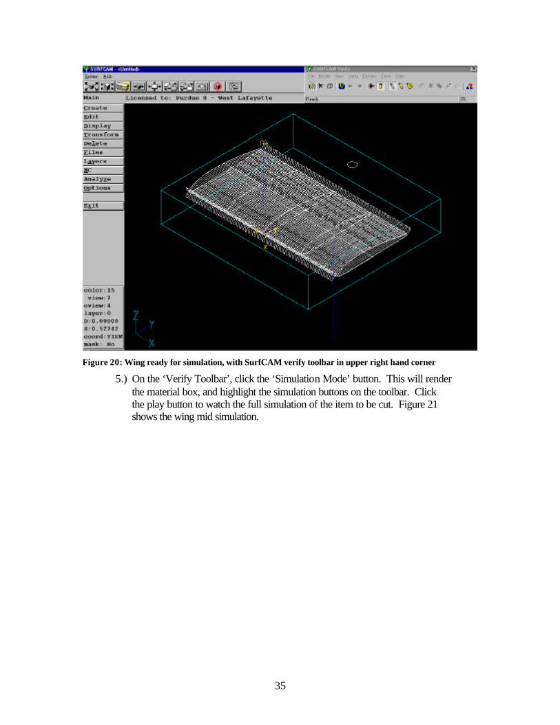
Figure 20: Wing ready for simulation, with SurfCAM verify toolbar in upper right hand corner
5.) On the ‘Verify Toolbar’, click the ‘Simulation Mode’ button. This will render the material box, and highlight the simulation buttons on the toolbar. Click the play button to watch the full simulation of the item to be cut. Figure 21 shows the wing mid simulation.

36
Figure 21: Simulation of wing being cut
6.) Click ‘Close’ after the file is finished being verified. As long as the file looked good in the verify mode, it will work on the actual machine.
7.) For each section, it will be necessary to POST the path to a file usable by the CNC machines. Simply click on each of the tool path sections (post the upper, lower, and holes files separately), change the machine to ‘CNC Router”, and click POST at the bottom of the file manager screen. After a short time of processing, SurfCAM will return a long file filled with data points. These will be read by the CNC machine, and will be translated into the motion of the actual bit.
8.) Save these files with any name, and the file extension *.tap. Without this extension, the CNC machine will not recognize the file and will not cut the piece.

37
Lab 3: How to create a mold
3.1 Objectives
1.) Setup a SurfCAM file to create a mold of a wing 2.) Machine a mold and prepare it for a lay-up 3.) Lay-up a wing surface using composite materials
3.2 Procedure
3.2.1 Brief Description of the Experiment
Composite materials are currently being effectively used in the Aerospace industry. The purpose of this lab will be to create a mold for composite materials to be ‘laid-up’ in. The wing skin being produced could be used, along with some stiffening material, to be the first component in a flight test vehicle, or a very robust wind tunnel model. Projects to use composite materials in a molding process include several Micro Air Vehicles, a wing for a high-speed pylon racing R/C airplane, and the wings for a 451 senior design project.
3.2.2 Notes on Input to SurfCAM
The molding process is much the same as the manufacturing of a wing. A mold represents the negative of the wing, but it can be used to create the positive using lay ups. Although the process is similar to the machining of a wing, there are a few subtleties to the mold that are necessary to review. The following procedure documents the current method of developing a mold. The first section of the procedure evaluates several ways to enter the airfoil coordinate data into SurfCAM to make the mold development process quicker.
There are three easy methods to enter the airfoil data into SurfCAM. The first would be to use toe data from the UIUC database of airfoils. This database has a wide variety of different airfoils for different purposes. The text files can also be edited fairly easily in Windows Notepad. The next method of entering the airfoil data would be to get the points lists from a program, such as MATLAB. Airfoil programs are prevalent in Matlab, and very easy to code. The third method to get airfoil data into SurfCAM is by using AutoCAD or IDEAS. Designs, saved as an AutoCAD *.dxf, or an IDEAS *.igs files, are actually compatible with the *.dxf and *.igs input in SurfCAM. This method works for full wing designs, also.
There are certain disadvantages to each of the above methods, however. The point file input to SurfCAM, making sure the file is in the proper *.asc format, depicts a full airfoil section. For the mold, it is necessary to have an upper and a lower section of the airfoil. The section in SurfCAM can be cut or trimmed to create these surfaces, but it is often easier to change the input file to ensure proper break locations. The upper and lower surfaces of the airfoil can be placed in separate files to make things easier, also. Caution must be taken to ensure that a complete airfoil section can be made from these two files, though. This means that if a file were taken and separated into the upper and

38
lower surface, each of these files must have a coordinate of (1,0) for the trailing edge, and of (0,0) for the leading edge (assuming the airfoil is of unit length, with the trailing edge positioned at (1,0)).
As mentioned before, AutoCAD and IDEAS files can be, and have been, used as input to SurfCAM. This is a quick and simple way to move from the design to the manufacturing stage. If a model is complicated, this may be the only way to move the design. However, there have been occasions where SurfCAM has imported these file types as a single line or surface. This reduces the amount of manipulation of the design once in SurfCAM. For a complicated design, this is very important as surfaces are defined to machine; for the case of the mold, this is most likely not an important issue.
The following lab and procedure will use the first method described here – using a point input, separated into two different files. The airfoil will be an Eppler 169, which is a symmetric airfoil. This means that the upper and lower surface molds would be the same (actually, any symmetric airfoil only needs one mold, unless time dictates that a mold of both surfaces be made, halving the production time).
3.2.3 Section Setup in SurfCAM
After the original airfoil file is separated into an upper and lower half, it is time to begin the mold development.
1.) Open SurfCAM. 2.) Move to the FILES menu, and click OPEN. 3.) Change the extension pull down menu to *.asc, and open the file you created
for either the upper or lower surface. In this case, the file is Eppler169_lower.asc.
4.) Bring the file in as a SPLINE. Onc ethe file is opened, change the VIEW to 7 – Isometric View, and change CVIEW to 1 – Top View. Also , change the frame of reference for SurfCAM to VIEW by pressing on the COORD field in the lower left hand of the screen. There should be just the lower surface of the airfoil on the screen, much like figure 22.

39
Figure 22: Airfoil input for lower surface mold
5.) Once the airfoil is in SurfCAM, other modifications need to be made before
the section is copied to make the mold form. From the main menu, click TRANSFORM.
6.) The section needs to be scaled along the y axis to change the chord length form 1 to something larger; the chord length will be 5 inches in this case. Press the SCALE button on the transform menu. Also make sure that MOVE is highlighted on the transform menu.
7.) Click VISIBLE for the object to move. Enter 5.0 as the scaling factor. 8.) For the point to scale about, click KEYBOARD, and enter the origin, (0,0,0). 9.) Return to the main menu. 10.) Click LINE. 11.) Click ENDPOINTS, then KEYBOARD. 12.) Lines will be created from the leading and trailing edges of the section to
create a flat surface on the mold to align the upper and lower sections after the molds are formed. On the Keyboard menu, enter the origin: (0,0,0). This should be the leading edge of the airfoil.
13.) Click KEYBOARD again and enter (0,-1,0) for the endpoint of the line. This completes the leading edge extension.
14.) On the create line menu, click KEYBOARD once again, enter the point (0,5,0) for the trailing edge location of the start of a new line.

40
15.) Using KEYBOARD one last time, set the end of this line to (0,6,0). There should now be two lines protruding from the front and rear of the airfoil section, as in figure 23.
Figure 23: Airfoil ready for mold development
The next part of the mold development process is to move the modified airfoil section to a location at the other end of the wing.
1.) From the main menu, press the TRANSFORM button 2.) Change the transform mode from move to COPY. Click DISTANCE. 3.) Change the MULTSELOFF button to MULTSELON, and then select
VISIBLE as the items to copy. Click DONE to finish the selection. 4.) In the coordinate box that comes up, enter x = 10, y = 0, and z = 0 for the
translation distance. Select only one copy.
5.) Press the button to see the results of the copy. Results should appear as in figure 24.

41
Figure 24: Mold progress after copying airfoil section
3.2.4 Surface Creation It is now time to create the surface for the mold, and a method to align the upper and lower surface after the two halves are machined.
1.) From the main menu, click CREATE. Click SURFACE. 2.) We will be making the surface from the two sections, and the lines, so click
CROSS SECT. 3.) Choose SECTIONS, and then click VISIBLE. Click DONE after the sections
are highlighted. 4.) Another menu may come up asking about the synchronization of the sections.
On the pull down menu, select ELEMENTS, and click OK. 5.) A surface will appear between the two cross sections, with an arrow at the
back end. Refer to figure 25.
42
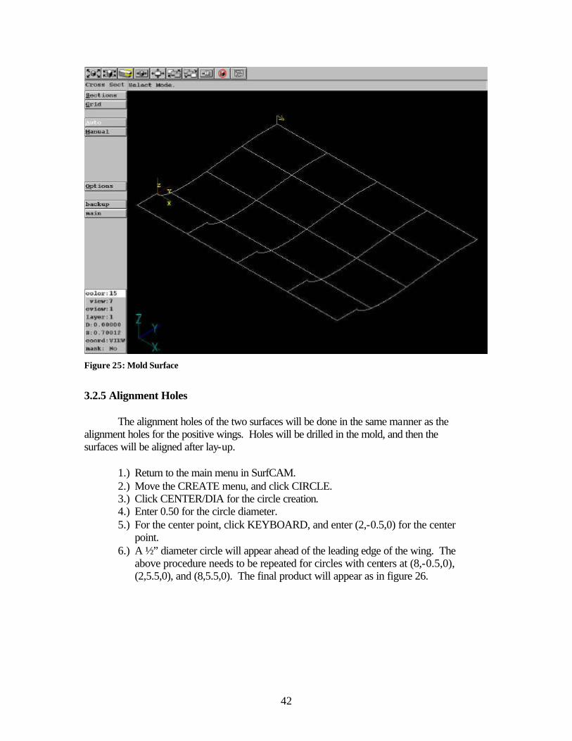
Figure 25: Mold Surface
3.2.5 Alignment Holes
The alignment holes of the two surfaces will be done in the same manner as the alignment holes for the positive wings. Holes will be drilled in the mold, and then the surfaces will be aligned after lay-up.
1.) Return to the main menu in SurfCAM. 2.) Move the CREATE menu, and click CIRCLE. 3.) Click CENTER/DIA for the circle creation. 4.) Enter 0.50 for the circle diameter. 5.) For the center point, click KEYBOARD, and enter (2,-0.5,0) for the center
point. 6.) A ½” diameter circle will appear ahead of the leading edge of the wing. The
above procedure needs to be repeated for circles with centers at (8,-0.5,0), (2,5.5,0), and (8,5.5,0). The final product will appear as in figure 26.

43
Figure 26: Alignment hole placement on mold
3.2.6 Tool Path Generation
The mold is now ready to have the tool paths generated. This procedure will be basically the same as the procedure for previous sections.
1.) From the main menu of SurfCAM, press the NC Button. Once in the NC
menu, make sure SurfCAM is in the 3-Axis mode. The mode is listed in the upper left hand corner of the screen. In the mode is not set to 3-Axis, press the NC MODE button, and then the 3-Axis button to change it.
2.) Select PLANAR from the 3-Axis NC menu. 3.) When SurfCAM asks for the surface to cut across, click on the yellow arrow
on the surface for the mold. Click DONE once the surface is selected. 4.) The 3-Axis Planar milling menu will come up. In set values as appropriate in
the following fields:

44
On the ‘Tool Information’ Page
Tool ½” HSS Ballnose, tool #6 Spindle Speed 10000 RPM
Feed Rate 30 IPM Plunge Rate 10 IPM
On the ‘Cut Control’ Page
Step Type Scallop Step Size 0.0025
5.) Click OK. 6.) SurfCAM will now ask for a point to begin the tool path on the surface. For
the mole, click on the ENDPOINT of the arrow that defines the surface. 7.) For the direction of the cut, click on the corner of the mold that is in the x-
direction of the mold. This will mean that the tool paths will be span wise on the wing.
8.) Click anywhere toward the leading edge on the lower surface to select the offset side for the cuts. The final sequence of cuts on the wing will resemble figure 27.
Figure 27: Span wise tool paths of the mold

45
Once the surface of the wing has been done, it is time to create the tool paths for the alignment holes. For these holes, a bit of smaller diameter than the hole will be used.
1.) Click the (operations manager) button on the tool bar at the top of the screen.
2.) A screen will come up the shows all of the tool paths created (only one at this time). Highlight this tool path, listed as ‘3axis Planar’.
3.) Click on the (hide path) button on the upper tool bar. This removes the previous tool path from view on the wing surface. This does not, however, remove the path from memory. This feature makes the creation of other tool paths and the manipulation of the surfaces easier.
4.) After the tool path is hidden, return to the main menu by clicking DONE on the Operations Manager screen.
5.) Return to the main menu of SurfCAM. 6.) Click on the NC button. For the alignment holes, the NC MODE needs to be
on 2-Axis. 7.) Select POCKET. Choose SINGLE. 8.) The process of choosing which alignment hole is drilled first does not matter.
Click on each of the four circles in succession. Click DONE. 9.) The 2 Axis Pocket menu will come up. Enter the following values in the
appropriate boxes (leave all other boxes/tabs alone): On the ‘tool information’ tab
Tool ¼” HSS End Mill Spindle Speed 10000 RPM
Feed Rate 30 IPM Plunge Rate 20
On the ‘cut control’ tab
Cutting Method Climb Pocket Cut Mode Spiral
Amount to Remove, In Z 0.25 in Plunge Type Plunge
Once all of these value shave been entered, press OK. The tool paths will be placed on the mold, and will appear like figure 28.
46
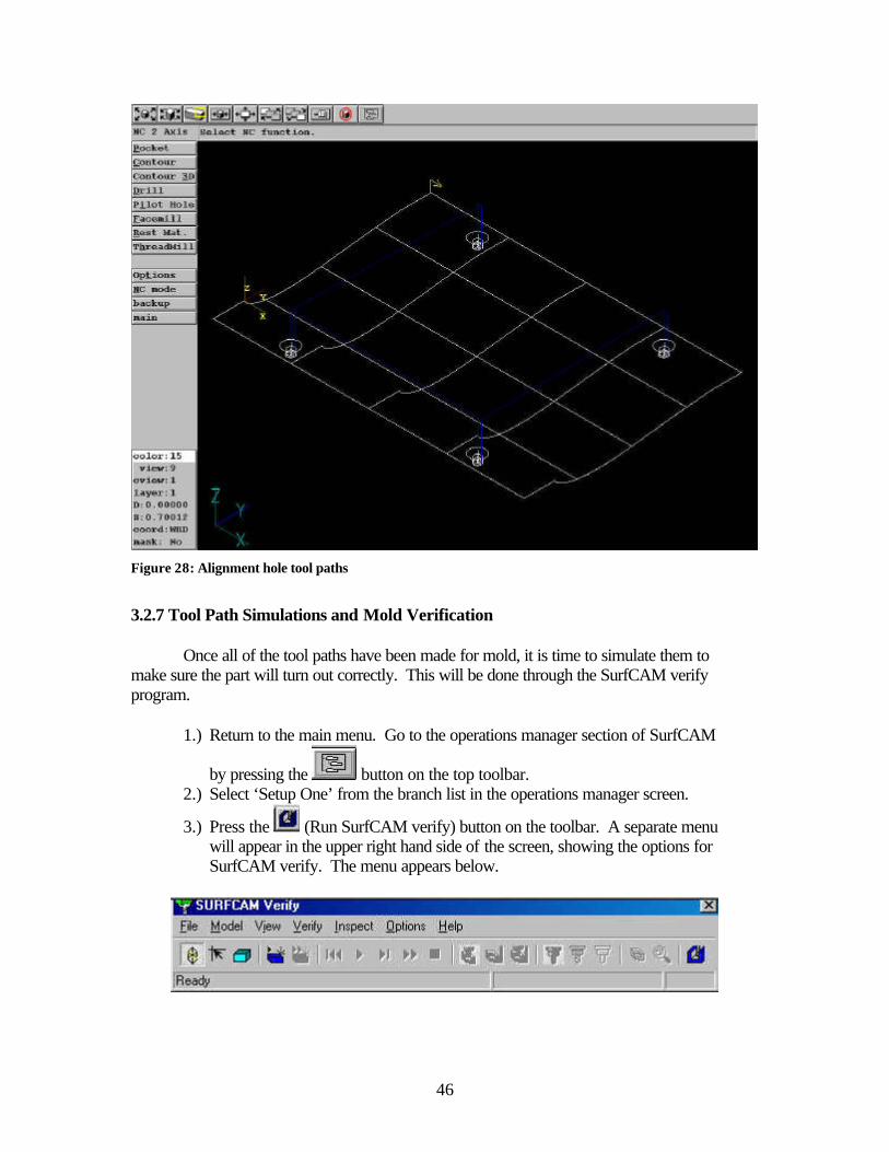
Figure 28: Alignment hole tool paths
3.2.7 Tool Path Simulations and Mold Verification
Once all of the tool paths have been made for mold, it is time to simulate them to make sure the part will turn out correctly. This will be done through the SurfCAM verify program.
1.) Return to the main menu. Go to the operations manager section of SurfCAM
by pressing the button on the top toolbar. 2.) Select ‘Setup One’ from the branch list in the operations manager screen.
3.) Press the (Run SurfCAM verify) button on the toolbar. A separate menu will appear in the upper right hand side of the screen, showing the options for SurfCAM verify. The menu appears below.

47
4.) Click MODEL on the menu. This will bring up another screen that will be used to create a virtual block of material around the mold part that will be machined in a computer simulation.
5.) Setup up the material to have the properties as seen in figure 29, then click ADD.
Figure 29: Setup of material stock
A blue box will appear around the mold section. This simulates a 2 inch thick piece of material, such as the blue foam commonly used to build wings.
6.) Click the (verify) button. This will make the predefined region into a solid model, representing the material to be machined.
7.) Click the (start) button to begin the simulation. The final image of the simulated cuts will appear as in figure 30.

48
Figure 30: Simulated mold cuts using SurfCAM verify
The final mold will be made from a block of wood, instead of blue foam, because it is much more durable, and easier to seal.
3.2.8 Finishing of the Wing Mold
Once the mold is cut from the wood, it must be finished to create a smooth final product. This finishing consists of 1.) sanding the wood to a smooth, splinter free surface; 2.) sealing the wood with a varnish or lacquer, and 3.) applying wax to the mold to allow removal of the surface after lay up.

49
Lab 4: Creating An Axial Flow Turbine
4.1 Objectives
1.) Use SurfCAM to create an axial flow turbine 2.) Generate tool paths in SurfCAM using a 4 Axis NC Mode 3.) Setup the CNC Jr. to cut using all 4 of the available axes 4.) Machine an axial flow turbine from aluminum
4.2 Procedure
4.2.1 Brief Description of the Experiment
This lab introduces the 4th Axis to create much more complicated items. With the 4th axis, items such as turbines and 3-sided fixtures may be machined easily. The principle of the 4th axis is a device that sits at one end of the table and rotates to coordinates specified by G-Code. The rotating plate has no limit to the amount of motion – any degree amount may be entered, including values over 360 degrees. For repetitive machine of a round object, the 4th axis saves time and reduces error by not requiring the object to be removed from a fixed object, remounted, and realigned. This lab will show the benefits of the 4th axis.
4.2.2 Setup of the Turbine in SurfCAM
The main source of airfoil coordinates, the UIUC Airfoil Database, does not list airfoils used for commercial turbines. However, since the purpose of this lab is not to replicate a larger scale turbine, these airfoils are not directly required. Instead, a highly cambered airfoil, a modified Eppler 420, will be used. The following procedure will get the turbine started.
1.) Open SurfCAM. 2.) Click FILES on the main menu. Click OPEN. 3.) Switch to the *.asc file extension, and move to the c:/aae490dbt/Lab 4
directory. Select the file e420_1.asc file. 4.) Enter the airfoil in as an NCURVE on the pull down menu. 5.) Change the VIEW to 7.) Isometric, the CVIEW to 1.) Top, and the COORD to
VIEW. The airfoil should look as it does in figure 31.

50
Figure 31: Airfoil input for Turbine
6.) Return to the main menu of SurfCAM. Click the TRANSFORM button. It will be necessary to adjust the size of the airfoil to get the blade size desired.
7.) On the TRANSFORM menu, click MOVE. Next, click SCALE. Choose SINGLE on the menu, and click on the airfoil.
8.) The length of the airfoil is approximately 1” when it is inputted. For the scale factor, enter 0.5.
9.) When prompted for ‘Point to Scale About’, click KEYBOARD, and enter the origin at the X, Y, and Z prompts. The airfoil will reduce to half the original input size.
It will also be necessary to adjust the angle of the airfoil, so the blade will have
some angle of attack to it. In a full size turbine section, the pitch of the blades will change along its length. Although this can be done, it is much more time consuming. For this purpose, the blades will be angled slightly, without twist. In addition, for time reasons, the stock being used for the props will be 2 5/8” diameter brass. This material is soft enough, that higher feed rates may be used, versus aluminum or steel. Follow this procedure to create the body of the turbine.
1.) Click TRANSFORM on the main menu. 2.) Make sure MOVE is highlighted on the TRANSFORM menu. Click
ROTATE.

51
3.) Select the airfoil for the ‘item to be moved’. A box will come up asking for the rotation angle (in a counter clockwise direction). Enter –20 for the rotation angle (degrees).
4.) Click KEYBOARD and enter the origin for the point of rotation. The airfoil should rotate slightly on the screen. See figure 32. (Two lines have been created here for effect only. These lines, along with the dimension, show the 20 degree rotation of the airfoil only. These items should not appear on the screen after the airfoil is rotated).
Figure 32: Rotated Airfoil
The airfoil is now at an angle, so it is now time to begin making the actual turbine. A hub will be required so the turbine can be mounted for both machining and for use afterwards. This hub will be constructed directly from a simple circle:
1.) Return to the main menu. Switch the CVIEW from 1.) Top View, to 5.) Right Side View. The Z-axis should now be pointing toward the bottom right of the screen.
2.) Click CREATE on the main menu. Click CIRCLE on the create menu. 3.) Select CIRCLE/DIA for the type of circle to create. The diameter box will
appear on the screen. Enter 1.625, and click ACCEPT. 4.) Using the KEYBOARD option, enter the origin for the center point of the
circle. Although it may not look like there is a circle on the screen, make sure

52
to use the (zoom extents) button. The screen should resemble Figure 33.
Figure 33: Turbine hub and airfoil
5.) Return the CVIEW to 1.) Top view.
The hub and blades can now be formed from the cross sections on the screen. This following procedure will take care of this.
1.) Click CREATE on the main menu. 2.) Choose SURFACE. Both the hub and all of the blades will be made from
these sections on the screen. 3.) Select EXTRUDE. At the prompt ‘Select vector for extrusion’, choose
KEYBOARD. Also at this time, make sure that the CVIEW is 1.) Top View, and the COORD is set to VIEW.
4.) Select X-AXIS for the axis to extrude about. Click ACCEPT. 5.) Enter 0.6 for the length of the extrusion, and select BOTH on the CAP pull
down menu. 6.) For the selection of the cross section to extrude, click SINGLE on the menu to
the right. Click the circle created earlier as the cross section to extrude. Click DONE. Three surfaces will appear on the screen, forming a cylinder. In the

53
middle of this cylinder will be the cross section of the airfoil. Refer to figure 34 to see what the turbine should now look like.
Figure 34: Turbine with hub surrounded with surfaces
7.) Return to the main menu, and click CREATE once again. Click SURFACE, and then extrude one more time.
8.) Again, click KEYBOARD, selecting the Z-AXIS this time. For the length this time, input 1.3. For CAP, select NONE. Click ACCEPT.
9.) Click SINGLE to select the airfoil cross section in the center of the hub. After the section is selected, click DONE. The airfoil will become a blade for the turbine. See figure 35 for the extruded blade and hub.

54
Figure 35: Hub with one blade extruded
There will be a need to move the blade back slightly, so the placement is better on the hub. This will be accomplished quickly using the following procedure.
1.) From the main menu, click TRANSFORM. 2.) Make sure MOVE is highlighted on the TRANSFORM menu. Click
DISTANCE. 3.) Click WITHIN on the menu. This will be used to highlight the blade and the
airfoil section that made it. To select the blade more easily, click on the VIEW button at the bottom right, and select 1.) Top View.
4.) Click on the screen to the upper left of the airfoil only. Using the cursor, highlight around the airfoil and the blade.
5.) In the menu that comes up to enter values to move the item, enter the following values:
X 0.05 Y 0.0 Z 0.0
Click OK, and the airfoil and blade should move along the x-axis only. See
figure 36 for the new placement of the blade, from the top view of the turbine.

55
Figure 36: New blade position, from the top view of the turbine
Once the first blade has been created, it is easy to create more blades about the hub.
1.) Return to the main menu. Click TRANSFORM. 2.) Make sure COPY is highlighted on the menu. Click ROTATE. 3.) Select SINGLE from the menu, and click on the blade. If MultSel is On, click
DONE. 4.) For the angle between blades, enter 60. This will produce 6 blades around the
hub. Click ACCEPT. 5.) SurfCAM prompts for a point to rotate about at this time. Before a point is
selected, the CVIEW must be changed to 5.) Right Side view. This is because SurfCAM rotates about the Z-Axis generally, and the blades need to be rotated about the centerline of the hub to be effective.
6.) After changing the CVIEW, click KEYBOARD on the menu. Enter the origin and click OK.
7.) For the number of blades to copy, enter 5 (6 total blades, one is already on the screen). Click ACCEPT. The blades should rotate about the hub, and produce a screen like figure 37.

56
Figure 37: Turbine with arrayed blades
Figure 38 shows the turbine rendered, for a better understanding of the project.
Figure 38: Rendered turbine

57
It will also be necessary to trim the blades of the turbine to the hub so SurfCAM does not see the interior surfaces as a place to machine.
1.) Return to the main menu of SurfCAM. Move to EDIT. 2.) Click TRIM/BREAK. 3.) Click on the trim button until it reads TRIM 2. This will be used to trim a
specific surface at the intersection of another. In this case, the turbine blades will be trimmed to the outer diameter of the hub.
4.) For the first element to trim, click one of the blades. For the ‘second element to trim or location,’ click SURFEDGE on the menu to the left. This specifies the surface edge of the hub to be used for the trimming action.
5.) Click on the outer edge of the hub. SurfCAM will automatically figure the intersection of the two surfaces, and trim the inner section of the blade off. Repeat this process for all of the turbine blades. Figure 39 shows the final result of the trimming.
Figure 39: Trimmed blades on the turbine
This finishes the creation of the hub in SurfCAM. The next step is to set up the tool paths. 4.2.3 Generating Tool Paths

58
Once the turbine has been placed in SurfCAM, tool paths can be created. The turbine will require the 4th Axis on the CNC Jr., and the 4th Axis option in the NC area.
1.) From the main menu, click NC. Click NC MODE, and select 4Axis. 2.) The 4 Axis cut menu differs from the 3 Axis by having less options for types
of cuts. For the Turbine, the blades will be cut using the SWARF command. 3.) Click SET AXIS. This is used to define the centerline of the object, which is
a reference for how it is mounted during machining. SurfCAM prompts ‘Select first point on rotation axis’. First return the CVIEW to 1.) Top View. Next, click KEYBOARD, and enter the origin.
4.) For the second point along the rotation axis, click KEYBOARD again, and enter 1.0 in the X-axis. Although there is no physical change in the image on the screen, SurfCAM now sees the rotation point of the item to be along the centerline of the hub.
5.) To begin the tool path setup, click SWARF on the 4th axis NC menu. SurfCAM prompts ‘Select a surface’. Only one surface may be selected at a time in the 4-Axis mode.

59
Procedure for Operating CNC Router Using Control Program SurfCAM, or another CAM program, will have generated a G-Code file. Transfer the file to the CNC router Terminal using a 3.5” floppy. The file should have the extension *.tap for the program to recognize it. Procedure for file transfer:
1.) Save G-Code file onto 3.5” floppy disk, making sure file extension is *.tap 2.) Place disk in drive of Router Control Computer 3.) At command prompt, type:
i. C:\>cd cnc ii. C:\cnc>copy a: yourfile.tap .
4.) This should copy your file with the *.tap extension to the directory. 5.) Type RUN at the C:\cnc> prompt. This should bring up the CNC Router
control program 6.) The following commands can be used to control the router:
a. G92 – Use to set the zero position for the tip of the router bit. i. USE: G92 X0Y0Z0 – This will set the origin for the tip of the
router bit b. G01 – Use to tell router to travel to a specific location
i. USE: G01 X0Y0Z0 – This will travel the router bit tip back to the predefined origin location from anywhere in the router area
c. F4 – Transit the router using the arrow keys at a rapid rate d. F5, F6, F7 – Transit the router using predefined increments, shown in
the control program e. F5 – 0.001-inch increments f. F6 – 0.01-inch increments g. F7 – 0.1-inch increments h. Arrow Keys – Control the X and Y Directions of the router i. PgUp – Move the router bit and motor in the +Z direction j. PgDn – Move the router bit and motor in the -Z direction
7.) Place the material to be cut on the Router Table. 8.) Secure the material to the board using one of two methods:
i. Large Steel clamps found in the top drawer of the desk. The
holes in the router table are used to secure the clamps with the bolts also found in the drawer.
ii. Drill holes through the material, in a location far from the routing area, and hold the material down with Drywall screws, found in the top, middle drawer of the desk.
9.) If a router tool path will go through the material you are machining, make sure there are no hold-down bolts under the tool path of the router. If the router bit

60
hits a hold-down bolt, it will damage the bit and possibly send metal pieces flying. Use caution in laying the material up for machining.
10.) Using the transit (arrow) keys, position the center of the router bit approximately where the zero location is, as shown in the part drawing. For a quicker accuracy, bring the router bit low to the surface of the material (not in contact with) and visually locate a center point.
11.) Use a sheet of paper to set the Z location on the material. The paper should be able to move between the material and the router bit tip, but with noticeable resistance.
12.) Use the G92 command to set the coordinate location of the tip of the bit. It is not always the case that the tip of the bit will represent the zero point on the material (where x, y, and z = 0).
i. Example: 2” foam is a commonly used material. Often a part lies within the bounds of the 2” thick material. To account for this, the tip of the tool is placed on the surface of the material, and this point can be defined as X = 0, Y = 0, Z = 1 (assuming the part is exactly one inch deep into the foam). This action automatically sets the zero also.
13.) Transit the router bit up 1 to 2 inches, to get it away from the material, by
using the G01Z1 command. 14.) To ensure the tool path is correct, it will be necessary to run the file and
‘cut air’. Re-Zero the Z location at this predefined distance away from the material, using G92Z0. This will prevent damage to the material during the first test of the tool path.
15.) Type the name of the file, including the .tap extension, and press enter. This should begin the routing process. This process is referred to as ‘cutting air.’ This free air cutting allows you to see mistakes in the tool path, or incorrect material position.
16.) Once the file has shown that it was generated correctly, stop the file first by using the Space Bar to pause, and then the ESC key to terminate the entire cut file.
17.) Re-transit the Z location back down the predetermined distance, again using the G01Z-1. This should put the router bit tip on the material. Re-zero the position in the control program, using G92Z0 (assuming the zero location is on the upper surface of the material being cut).
18.) Select the appropriate RPM on the side of the router motor, and turn the motor on.
19.) Making sure all guards are up, all safety equipment is on, and all hands are out of the area, re-type the file name with the .tap extension. This should begin the routing process. If you need to stop the machine during the routing process, make sure to press the SPACEBAR first, and then the ESC key to terminate the file. In emergencies, use the red emergency stop button located near the computer. This stops the motion of the router head. This button DOES NOT stop the rotation of the bit or the router motor.

61

62
Models created on dT Technologies CNC Router Laminar Flow Body – Shann Rufer Wooden Dragster Wing – Amato 8 – David Ong Dragster Wing Mold – Eppler 423– David Ong Micro Air Vehicle Mold – Pat Foam C-Wing – Steve Wulf & Shawn Russel Wooden C-Wing – Steve Wulf & Shawn Russel Rigid Sail (3 sections) – Bradley Gifford Blue Fin Tuna Laminar Flow Body Micro Air Vehicle Mold - Thomas Scmidt-Lange Micro Air Vehicle Mold – Ben Cardinal S – Duct for UCAV – Professor Sullivan High Contraction Wortmann FX 63-137 – Steve Wulf Wooden ‘Oscar’ Model for 451 Spring 2000 – Jason Helms Foam ‘Oscar’ Model for 451 Spring 2000 – Jason Helms Large Scale Eppler 327 wing – Professor Thompson Wooden Flying Wing Design for 451 Spring 2000 – Andrew Peters Wings for ‘Jester’ aircraft for 451 Spring 2000 – Steve Wulf Half Scale rear wing for ‘Jester’ aircraft – Steve Wulf Small Laminar Flow Body – Bridget Fitzpatrick