Embed Size (px)
Citation preview

6000MCNC Control
TRAINING GUIDE
Navigation Instructions
Follow the bookmarks at the left sideof the page to navigate to desired topic.
Click plus and minus symbols to expandand compress menu display.
Bookmarks

5000M CNC CONTROLTRAINING GUIDE

1.
Turning the Control ON
F10After the control has been turned ON press F10 to continue.
Then press ENTER to select CNC mode.
1. Control Software This allows you enter CNC software2. Setup Utility Machine configuration3. Motion Setup/Testing Used to setup drive

2.
First CNC Screen
SECTION #1
SECTION #2
SECTION #3
Control Manual Screen

3.
Program name Machine status
Mode of operationMachine position status
Messages display in this areaError and warnings
Command line for MANUAL(MDI) instructions
Position relative to machine HOME
Position relative to part ZERO
Target or position to reach
Distance to go to reach target
Section #1
Section #2

4.
Section #3
Active tool #
Tool diameter
Tool length offset
Spindle speed
FeedratePercentage offeed and RPM’s
Number of loops
Dwell in seconds
Active fixture offset
Active M functions
Active G codes
Override of feed and rapid
Parts counter and timer

5.
Softkey in Manual ModeAccess help
menu
Access list ofprograms
Edit programin memory
Manual Mode
Single StepMode
AutomaticMode
Delete fromcommand line
Insert in command line
Access tool page
Activatehandwheel
Softkey in Manual mode when shift key is pressed
Display last 8 messages Teach Mode
Sends machine home
Exits back mainmanual screen
Note:When handwheel is active colors will be reversed in boxas shown below.
F10

6.
Alfa - Numeric key boardNote :- Most used key are yellow . Most key also double functions , the
shift key is use to use secondary functions.
D
A C D
C
B
F G H
I K LJ
M O PN
Q S TR
U WV
X 8 97
Y 5 64
Z 2 31
0
<
{ $
Clear key
Enter key
Cursor keysSpace key
Shift key
> ^
[ ] !
~ @
}
_ ‘/
? :
% “
| ; /
( ) #
*
&
=
‘
Rapid Feed Arc
Feed Tool Mcode
mm/in Dwell Plane
R.M.P....

7.
% FEED
X
Y U
W
AXIS % SPDL OVRD
1
10100
FEED
JOG
RAPIDSERVORESET
SPDL OFF
SPDL REV
SPDL FWD
+
COOL READY
Z
Manual panel
There are two type of Manual panels.1.As shown below.2.The other without Handwheel on left side
Manual handwheel
Axis select for handwheel
Feedrate override
Axis feed type
Spindle override
Servo reset
Direction key for manual
Manual spindle keys
HoldStart
Emergence stop
8.
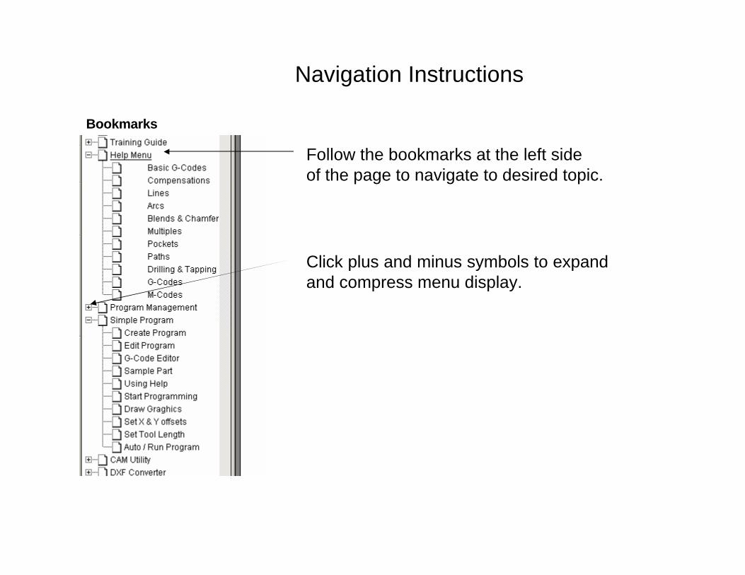
MOVING WITH COMMANDS
Type commands as needed and press the START button located on theMANUAL PANEL
EXAMPLE:
Type: G0 G90 Z-5. and press Start Z axis goes to Z-5. in ABS and RAPID
EXAMPLE:
Type G97 S1000 M3 and press START to start the spindle at a fixed 1000rpm.
MOVING WITH JOG MOVEMENTS
1) Turn the jog mode selector switch on the MANUAL PANEL to 100, 10, 1, FEED or
RAPID
2) Select the axis to move with the AXIS SELECTOR switch at the MANUAL PANEL
3) Press the or the key to move in the desired direction._ +

9.
MOST COMMON G-CODE COMMANDS TO REMEMBER:G00: Rapid move.
G01: Feed move.
G02: Arc clockwise
G03: Arc counter clockwise
G17: XY plane
G18: XZ plane
G19: Yz plane
G40: Cutter comp off
G41: Cutter comp left
G42: Cutter comp right
G53 Ox: Fixture offsets ( absolute shift from Machine Home).
G70: Inch programming
G71: MM programming
G80: Used for Drilling Cycles.
G90: Absolute co-ordinate system
G91: Incremental co-ordinate system
G92: Incremental shift
G94: Feed Rate in Inch per minute (mm per minute).
G95: Feed Rate in Inch per revolution (mm per revolution)
M0: Stop program .
M2: End of program
M3: Spindle forward
M4: Spindle reverse
M5: Spindle OFF
M8: Coolant ON
M9: Coolant OFF

10.
ADDRESS LETTERS USED IN PROGRAMMING
A: Used for angles around X axis.B: Used for angles around Y axis.C: Used for angles around Z axis.D: Designates tool diameter in a program.F: Feedrate.I: Circle center X axis.J: Circle center Y axis.K: Circle center Z axis.L: Dessignates tool length in a program.M: Miscellaneous functions.N: Line number prefix.O: Program or subroutine number prefix.P: Subroutine number call prefix. S: R.P.M. prefix.T: Tool call.U: Rotary axis or spindle.V: Rotary axis or spindle.W: Rotary axis or spindle.LOOP: Repete operation.END: End of loop.
Note: Some of these letters are used inside canned cyclesalso some that are not listed above.

11.
Programs can be restored into the control if they have been previously saved on a disk.
From the MANUAL mode press then press SHIFT
Next, press select “A:” and press ENTER
Using the arrow keys hi-lite the program to be restored and press
then press twice to select COPY and then C:
RETREIVING PROGRAMS FROM DISK
Insert the disk into the floppy disk drive (A:) on the machine.
Transferring a program from a disk into the control
Program
Log
Utility
WARNINGRemove the diskette when complete and save in a safe place. Donot leave the diskette in the machine, the will not start correctlywith disk in the drive.
12.
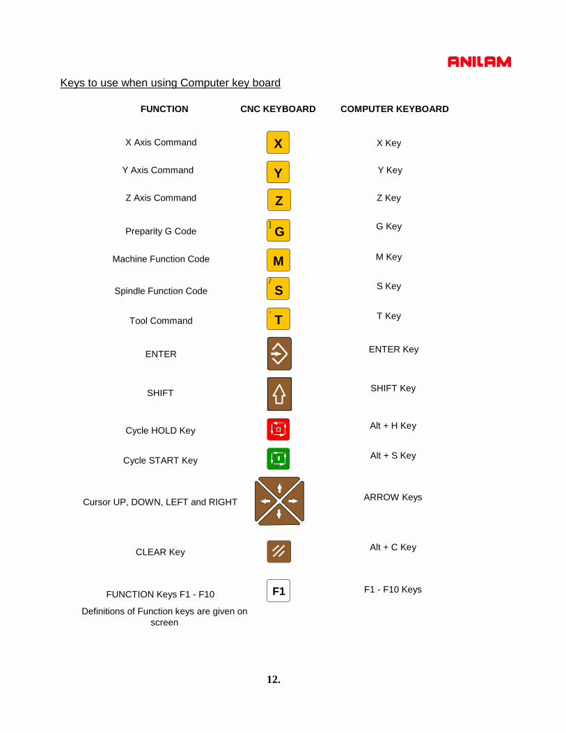
FUNCTION CNC KEYBOARD COMPUTER KEYBOARD
Z Axis Command
X Axis Command
Preparity G Code
Machine Function Code
Spindle Function Code
Tool Command
ENTER
SHIFT
Cycle HOLD Key
Cycle START Key
Cursor UP, DOWN, LEFT and RIGHT
CLEAR Key
FUNCTION Keys F1 - F10
Z Key
X Key
G Key
M Key
S Key
T Key
ENTER Key
SHIFT Key
Alt + H Key
Alt + S Key
ARROW Keys
Alt + C Key
F1 - F10 Keys
X
Z
M
S
T
F1
Definitions of Function keys are given on screen
YY Axis Command Y Key
G]
/
‘
Keys to use when using Computer key board

5000M CNC CONTROLHELP MENU’S

1
HELPF1The HELP MENU’S are access by pressing.
This can be done from either Manual or Edit.
Manual mode soft keys
Edit mode soft keys
First Help screen
Note: The center of the screen. There are two different displays, one has text about Help the other shows the program as it is being entered.
Press will toggle these screens.F4 Text

2
ExitF10
F3
F4
F5
F6
F7
F8
F9
F1
F2
Text
Select
ReEdit
Abort
Accept
Prev
There are two different set of soft keys , as shown above.
Arrow up and around to desired selection.
Arrow down and around to desired selection.
Not used.
Text changes center of screen to diplay program.
Selects required cycle.Enter will as do this.
ReEdits a cycle after it is already in a program.
Goes back to edit without saving last set of inputs.
Accepts inputs and stays in HELP.
Goes back to previous page in HELP menu.
Exits to EDIT page and saves inputs.
3
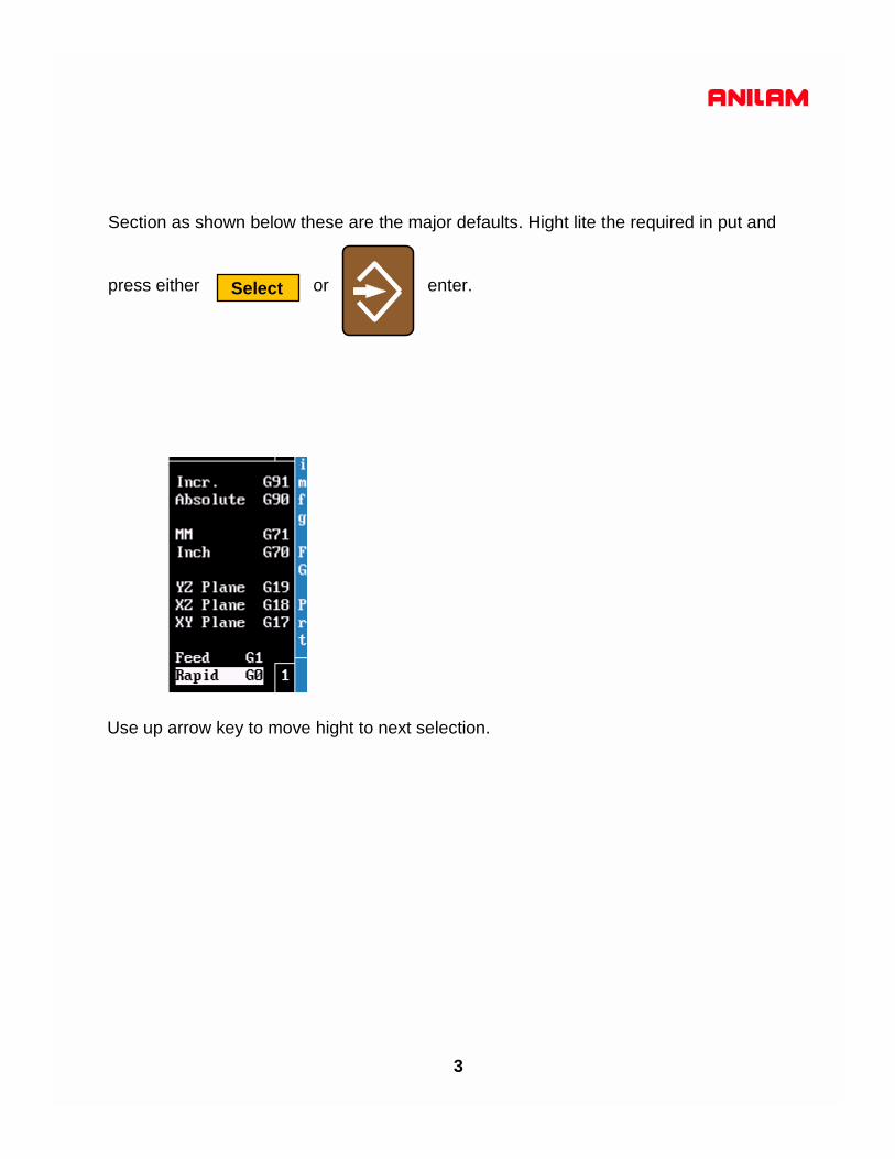
Section as shown below these are the major defaults. Hight lite the required in put and
press either or enter.Select
Use up arrow key to move hight to next selection.

4
Press the number 2 key or arrow up to number 2 .
Press either or enterSelect
Note:- the reverse color around Compensation.
Press either or enterSelect
1. Puts a G40 into program comp off.2. Enters G41 into program cutter comp left.3. Enters G42 into program cutter comp right.4. G68 rotates a shape around a center.5. G72 scale program to required size.

5
Center of rotation X axis.Center of rotation Y axis.Start angle when using loop.Angle between loops or single shot.Subroutine #.Number of repeats.
This cycle can be programmed in main program or in a subroutine. If programmed in the main, the cycle is entered and then the diminsion of the shape and turned off with a G68.
This example is show rotation just one time not usinga subroutine,note the G68 to turn off rotation.
Example on left show rotation using subroutine,note there is no G68 turning off rotation ,it’s notrequired when programming this way.
Rotation G68
Note:The only entry that has to be program is C because it has 0 (Zero’s)next to it.

6
Scaling G72
When using scaling if threre are any the axis must be scaled the sameon both of these axis.If part is required to be half size .5 would be factor.G72 alone will turn off scaling.
7
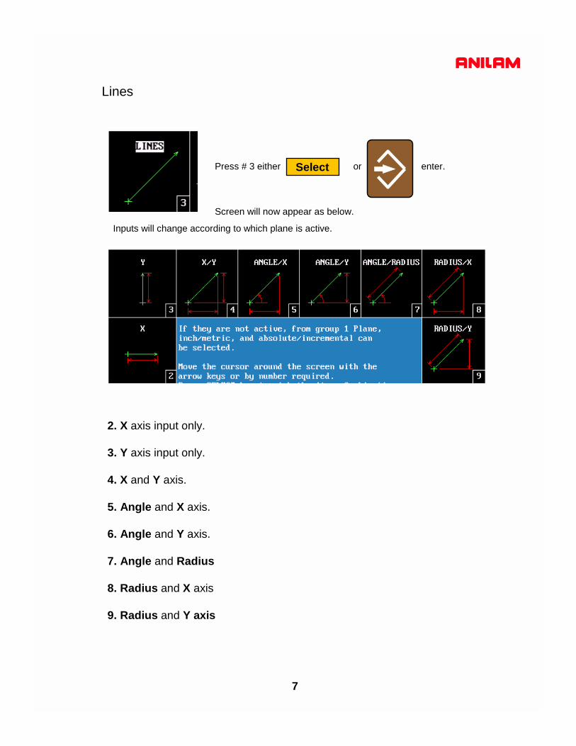
Lines
Press # 3 either or enter.
Screen will now appear as below.
Select
2. X axis input only.
3. Y axis input only.
4. X and Y axis.
5. Angle and X axis.
6. Angle and Y axis.
7. Angle and Radius
8. Radius and X axis
9. Radius and Y axis
Inputs will change according to which plane is active.

8
Arc’s
Press # 4 either or enter.
Screen will now appear as below.
Select
2. Radius and End Point.
3. Center and End Point. This can be used for helical interpolation (thead mill.)
4. Center and X End Point.
5. Center and Y End Point.
6. Center and Angle. Angle is dependant Absolute or increamental.
7. Arc and Line. Inputs are Radius, Angle and End Point X and Y
8. Line and Arc. Inputs are Angle, Radius and End Point X and Y
9. Arc and Arc. Inputs Center X and Y first arc, Center X and Y second arcand End Point X /Y
Tool must be at start point before inputting arc’sCenters of arcs X=I , Y=J and Z=KInputs will change according active plane.

9
Corner Rounding And Chamfering
Press # 5 either or enter.
Screen will now appear as below.
Select
2. Radius One shot corner rounding.Inputs mid point X / Y,radius and end point X/Y.
3.Chamfer One shot chamfer. Inputs mid point X/Y, chamfer andend point X/Y.
4.Corner Radius Modal command puts radius on all intersects.
5.Corner Chamfer Modal command puts chamfer on all intersects.
6.Cancel Cancels #4 and #5

10
Multiple line, arc and chamfer moves.
Press # 6 either or enter.
Screen will now appear as below.
Select
2. Definition Inputs first angle, second angle and end point.
3.Radius Inputs first angle, radius, second angle andend point.
4.Chamfer Inputs first angle, radius, second angle and end point.
5.Rad/Rad Inputs first angle, first radius, second angle,mid point, second radius and end point.
6.Chamf/Chamf Inputs first angle, first radius, second angle,
7.Rad/Chamf Inputs first angle, radius, second angle, mid pointX/Y chamfer and end point.
8.Chamfer/Rad Inputs first angle, chamfer, second angle, mid pointX/Y, radius and end point.
Tool must be positioned at start point.Inputs will change according to active plane.

11
Pockets
Press # 7 either or enter.
Screen will now appear as below.
Select
Cutter comp is built into all pocket except Mold Rotation.X and Y centers are Optional but if not entered will assume it is positioned at centerof pocket.
#2. Frame Milling.#3. Hole Milling.#4. Circular Pocket.#5. Rectangular Pocket.#6. Area Clearance.#7. Mold Rotation.#8. Elbow Milling.#9. Draft Pocket./ . Plunge pockets.
Plunge Pockets#2. Circular Plunge Pocket#3. Rectangular Plunge Pocket.
Leave island in middle of pocket.Enlarges existing hole, used on smaller holes.Cuts flat bottom circular pocket.Cuts flat bottom rectangular pocket.Cuts irregular shape pocket and takes profile cut.Rotates a profile around an axis.Produces a radial groove.Rectangular pocket with angled sides.Rectangular and circular pocket plunging straight down.
Plunges straight into material.Plunges straight into material.

12
Hole Milling G76
A good use for this cycle to produce small counterbores.
DiameterRough FeedFinsih StockFinish Feed
DJSK
Diameter of pocket.Feedrate roughing.Finish Stock.Feedrate finish pass.
X Center Y Center Length Width Start Hgt. Z Depth (abs)Stepover Max. Z cutRamp FeedRough FeedInside Rad.Outside Rad.Frame WidthFinish StockFinish FeedRetract Hgt.
XYMWHZABIJUVCSKP
Center of pocket X axis.If not entered will assume tool is at center of pocket.OptionalCenter of pocket Y axis.If not entered will assume tool is at center of pocket.OptionalLength of island (X).Width of island (Y).Start height .1inch or 2mm above top surface of pocket.Absolute depth to bottom of pocket.Cut per pass, not to exceed 70% of cutter dia. Negative value path will climb mill.Depth per pass Z axis.OptionalFeedrate when feeding down into pocket. OptionalFeedrate roughing pocket.OptionalRadius on corners of island.Radius on outside, will assume cutter radius if no entry. OptionalDimension from island to outside.Amount of material left for finish pass.OptionalFeedrate for finish pass.OptionalHigh retract allows tool to be move above the surface part when finished. Optional
Frame pocket G75Only the input with in Zeros have to be entered the rest are optional. It will assume being at the centerof pocket if no dimension are entered.

13
Rectangular Pocket. G78XYMWHZUABIJSKP
Center of pocket XCenter of pocket Y
Actual length X axis
Actual width Y axis.1 above surface to be cutAbsolute depth of pocketRadius in corners70% of cutter or lessMax depth per passFeedrate on 3 axis first moveFeedrate for roughingAmount of stock for finish cutFinish feedrateRetract after finished.
X CenterY CenterLengthWidthZ Start Hgt.Z Depth (abs)Corner Rad.StepoverZ Max. CutRamp FeedRough FeedFinish StockFinish FeedRetract Hgt.
Circular pocket G77
X CenterY CenterZ Start Hgt.Z Depth (abs)DiameterStepoverZ Max. cutRough Feed.Finish StockFinish Feed.Retract Hgt.
XYHZDABISKP
Center X axis. OptionalCenter Y axis. OptionalStart height .1 above surface to be cut into.Absolute Z depth.Diameter of pocket, comp built in. Move over per pass. OptionalMax. Z depth per pass. OptionalFeedrate roughing. OptionalAmount of material left for finish pass. OptionalFinish pass feedrate. OptionalHigh returnwhen finished. Optional

14
Mold Rotation G45
Start Angle End AngleNum of CyclesNum of Fwd SubNum of Rev SubAxis of RotationOther axis CLCenterlineRotation Angle
ABCFRXIJK
Angle where rotation is going to startAngle where rotation is going to end 1 cycle equals 1 Fwd and 1 Rev. Sub.Sub. Profile forward directionSub. Profile Reverse directionAxis rotation is around X,Y or ZCenter line X or Y if not ZeroCenter line Z Axis if not ZeroAngle rotation Z axis only
Input Sub # XYZ Start Hgt.Z Depth (abs)Cut AngleX StartY StartStepoverZ Max. CutRamp FeedRough FeedFinish StockFinish FeedRetract Htg.
WXYHZCDEABIJSKP
Subroutine number.X position tool will Z down into part Y position tool will Z down into part Start height .1 above top of pocketTotal depth of pocket absoluteUsed if starting in middle of radiusPosition of cut at start X axis. OptionalPosition of cut at start Y axis. OptionalCutter stepover each passMax depth of cut per pass.Ramp feedrate Z downRough feedrateStock left for finish passFinish feedrateRetract after finished.
Area Clearance G169.

15
Draft Pocket G73
Length, bottom Width, bottom Start HeightZ Depth (abs)Lower Left Rad.Lower Right Rad.Upper Left Rad.Upper Right Rad.Draft AngleZ step RoughMax XY StepoverFinish Stock XYZ step FinishFinish FeedFlat 0, Ball 1
XYHZABCDEIVSQRW
Length at bottom of pocket. requiredWidth at bottom of pocket. required Height above part to rapid. requiredAbsolute depth requiredLower left Radius requiredLower right radius optional Upper left radius optionalUpper right radius optionalDraft angle Degrees requiredDepth per pass in Z axis requiredMaximum stepover XY optionalFinish stock XY optionalZ step finish pass optionalFinish feedrate optionalFlat mill = 0 Ball mill = 1 optional
Note: Tool must be positioned at centerof radius bottom left corner.Center of pocket must be clearedbefore using this cycle.When using flat endmill will go toprogrammed depth. If ball endmill uses will only go todepth minus cutter radius, .5 millAbsolute depth -1 actual depthit would go to is -.75.
Elbow Milling G49
Start Radius End RadiusIncluded AngleNum of CyclesX CenterY CenterDirection CCW+End AngleStart AngleCtr. Line RadiusRapid HeightStart HeightRough FeedFinish StockFinish Feed
BKACIJDFERZHUSV
Radius at start of ElbowRadius at end of Elbow Included angleSub. Profile forward directionSub. Profile Reverse directionAxis rotation is around X,Y or ZCenter line X or Y if not ZeroCenter line Z Axis if not ZeroAngle rotation Z axis onlyRadius at center of elbowStarting hieght above surface.Z height to startRough feedrateAmount of stock for finish passFeedrate for finish cut

16
Plunge Circular Pocket G177
Plunge Pocket Pocket G178
X CenterY CenterZ Start Hgt.Z Depth (abs)DiameterStepoverZ Max. cutZ FeedrateRough Feed.Finish StockFinish Feed.Retract Hgt.
XYHZDABIJSKP
Center X axis OptionalCenter Y axis. Same as above. OptionalStart height .1 above surface to be cut.Absolute Z depth.Diameter of pocket, comp built in. Move over per pass. OptionalMax. Z depth per pass. OptionalFeedrate plunging OptionalFeedrate roughing. OptionalAmount of material left for finish pass. OptionalFinish pass feedrate. OptionalHigh returnwhen finished. Optional
XYMWHZUABIJSKP
Center of pocket X Center of pocket YActual length X axisActual width Y axis.1 above surface to be cutAbsolute depth of pocketRadius in corners70% of cutter or lessMax depth per passFeedrate on 3 axis first move Feedrate for roughingAmount of stock for finish cutFinish feedrateRetract after finished.
X CenterY CenterLengthWidthZ Start Hgt.Z Depth (abs)Corner Rad.StepoverZ Max. CutRamp FeedRough FeedFinish StockFinish FeedRetract Hgt.
High lite plunge pockets press

Pockets with Islands (G162) Format: G162 An Bn Cn Dn En
This cycle allows islands in irregular pockets. The main pocket must the lowest subroutine number. Normally, this would be one (1). Pockets with Islands can be programmed using: • DXF (see “Section 17, Using DXF for Pockets with Islands
(G162)”) • CAM (see “Section 18, Example #12 Using CAM for Pockets
with Islands (G162)”) • Subroutines More than one G162 Island cycle can be programmed at a time. They may be strung together, but on separate lines. Islands can be programmed inside of islands. Five islands can be put on a line. The shape number subroutine number is used as inputs.. Refer to Table 5-21.
Activate a tool prior to programming G78, so cutter diameter is known. Table 5-21, G162 Address Words
Address Word
Description
A First island. Required. B Second island. Optional. C Third island. Optional. D Fourth island. Optional. E Fifth island. Optional.
Using Subroutines for Pockets with Islands The program below is the same one used in the DXF portion with subroutines added for the letters. In the third G162 some of the numbers have negative sign (-) in front of them, this changes the side of the cutter comp for the islands in islands. See Figure 5-13, Subroutines Pockets with Islands Example Workpiece and Table 5-22, Pockets with Islands Subroutines Programming Example.

Figure 5-13, Subroutines Pockets with Islands Example Workpiece
Table 5-22, Pockets with Islands Subroutines Programming Example N1 G00 G17 G70 G90 N2 T1D.0205 L-1 M6 N3 S1250M3 N4 M8 N5 G53O01 N6 G162 A2 B3 C4 D5 E6 N7 G162 A7 B8 C9 D10 N8 G162 A-11 B12 C-13 D-14 N9 G169 W1 H0.1 Z-0.0050 C299. A0.0080 I5.0 J12.0
S0.0010 K10.0 P1 N10 M2 N11 N12 O11 N13 X1.1044 Y0.5 N14 Z0.1 N15 G01 Z-0.005 N16 G01 X1.159 Y0.65 N17 X1.2052

N18 X1.2598 Y0.5 N19 X1.2226 N20 X1.2135 Y0.525 N21 X1.1507 N22 X1.1416 Y0.5 N23 X1.1044 N24 G00 Z0.1 N25 M99 N26 N27 N28 O12 N29 X1.1634 Y0.56 N30 Z0.1 N31 G01 Z-0.005 N32 G01 X1.1821 Y0.6112 N33 X1.2007 Y0.56 N34 X1.1634 N35 G00 Z0.1 N36 M99 N37 N38 O13 N39 X1.4007 Y0.55 N40 Z0.1 N41 G01 Z-0.005 N42 G01 X1.3612 N43 G02 Y0.6 I-0.0312 J0.025 N44 G01 X1.4007 N45 G03 Y0.55 I-0.0707 J-0.025 N46 G00 Z0.1 N47 M99 N48 N49 O14 N50 G0 X1.42Y.5 N51 G1 X1.42Y.65 N52 G1 X1.460 Y.65 N53 G1 X1.460 Y.5 N54 G1 X1.42 Y.5 N55 M99

17
#2. Ellipse.#3. Spiral.#5. Facing.#7. Circular Profile#8. Rectangular Profile.
Produces an ellipse, uses special cutter comp.Will cut a tapered thead.Faces large surfaces.Cut circle either inside or outside.Cut rectangle inside or outside.

18
Ellipse G05
Spiral G06
Note: All dimensions are INCREMENTAL.
End HorizontalEnd vertical.Center HorizontalCenter VerticalHalf lenghtHalf widthCCW +,CW -.
XYIJABL
Distance from start to end X axis.Distance from start to end Y axis.Distance to center from start.Distance to center from start. Half length of ellipse x axisHalf width of ellipse Y axis.Direction of cut.
Note: All dimensions are INCREMENTAL.
End HorizontalEnd vertical.End Depth ZCenter HorizontalCenter VerticalNumber of revolutionCCW +,CW -.
XYZIJL
Distance from start to end X axis.Distance from start to end Y axis.Distance from start to end Z axis.Distance to center from start.Distance to center from start. Number of turn it will make.Direction of cut.
Cutter comp for ellipse uses M1040 X0 = off, X1 = outside and X2 = inside.Cutter must be positioned in compensated position before ellipse is programmed.
No compensation available for spiral.

19
Facing G170
LengthWidthX StepoverY StepoverFeedrateZ Start hieghtZ Depth Absolute X StartY Start
XYABFHZDE
Increamental length X axis.Increamental width Y axis.Stepover X .Stepover Y.Feedrate. Start height .1 above surface.Finish depth.Start X axis.Start Y axis.
Note: Only A or B not both can be used.Cutter will step away from start cornerby half the cutter diameter.

20
Circular profile G171
Rectangular Profile G172
Center X.Center Y.Start height.Diameter.Z depth (absolute).0 = inside, 1 = outside. Ramp Distance.Z Maximum cut.Finish Stock.Z Feedrate.Rough feedrate.Finish Feedrate.Retract height.
XYHDZARBSIJKP
X Center (optional).Y Center (optional ).Start height above surface to be cut.Diameter of pocket (actual).Depth to be cut (absolute). 0 insde ,1 outside of circle.Size of ramp on radius.Maximun depth in Z per pass.Amount of stock left for finish cut.Feedrate in Z axis.Feedrate for roughing.Feedrate for finishing.High retact if higher than H value.
Center X.Center Y.Start height.LengthWidth..Z depth (absolute).0 = inside, 1 = outside. Ramp Distance.Corner radiusZ Maximum cut.Finish Stock.Z Feedrate.Rough feedrate.Finish Feedrate.Retract height.
XYHMWZARUBSIJKP
X Center (optional).Y Center (optional ).Start height above surface to be cut.Length of pocket X axis (actual).Width of pocket Y axis (actual)Depth to be cut (absolute). 0 insde ,1 outside of circle.Size of ramp on radius.Radius in corners.Maximun depth in Z per pass.Amount of stock left for finish cut.Feedrate in Z axis.Feedrate for roughing.Feedrate for finishing.High retact if higher than H value.

Thread Mill Cycle (G181) Format: G181 Xn Yn Zn Hn Pn Dn Cn Bn Rn Sn En Jn Kn Vn
WARNING: The first move in this cycle is a rapid move to the center of the thread before moving the Z axis. Make sure the tool is properly located before calling up this cycle.
Use the thread milling for cutting inside or outside threads. It will cut either Inch or MM, left or right hand, and Z movement up or down. A single tooth or multi-toothed tool may be used. Start can be at the top or bottom of the hole or boss. The tools are set, as you would normally set TLO.
Programming the Thread Mill Cycle To program the Thread Mill Cycle: 1. In Edit mode, press Help (F1), select PATHS from the menu,
then “THREAD MILL” to display the G181 Thread Mill pop-up menu (refer to Figure 5-20).
2. Complete the entry fields (refer to Table 5-28, G181 Address Words), and press EXIT (F10).
Depending on the parameters used and their values, when cutting a thread, the tool can ramp into the cut as illustrated in Figure 5-20. See Table 5-28, G181 Address Words.
THREADMILLPU
Figure 5-20, Thread Mill Pop-up Menu
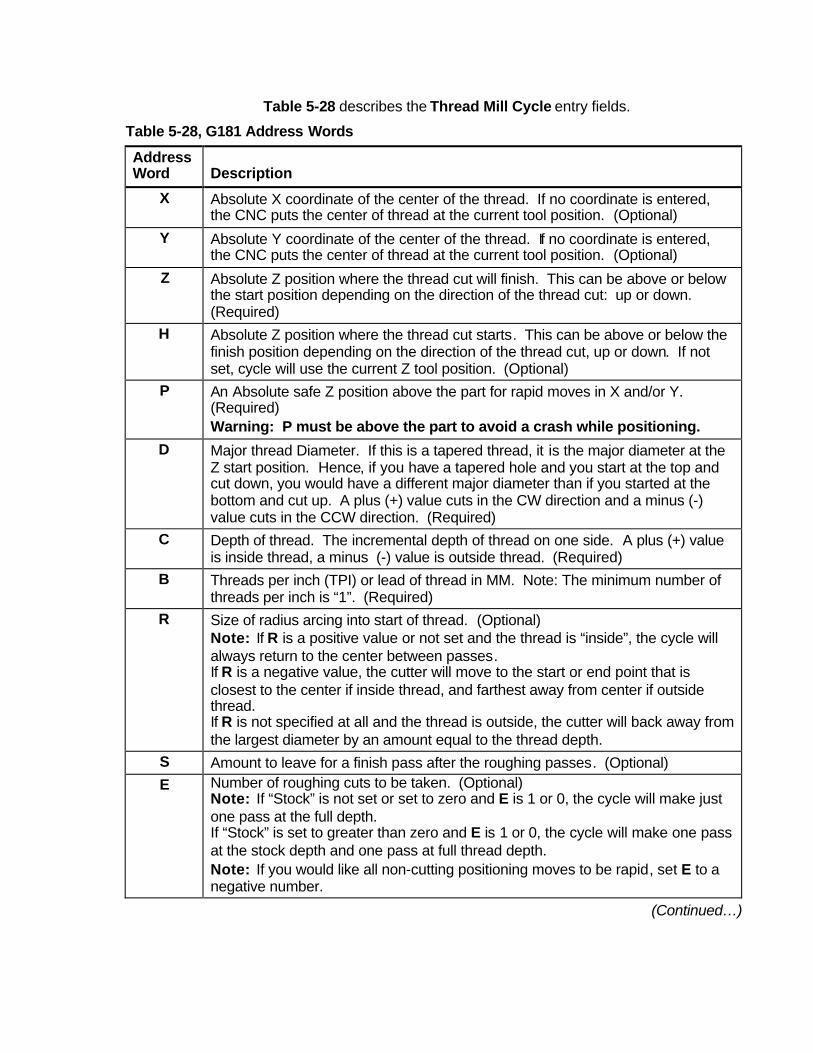
Table 5-28 describes the Thread Mill Cycle entry fields.
Table 5-28, G181 Address Words
Address Word
Description
X Absolute X coordinate of the center of the thread. If no coordinate is entered, the CNC puts the center of thread at the current tool position. (Optional)
Y Absolute Y coordinate of the center of the thread. If no coordinate is entered, the CNC puts the center of thread at the current tool position. (Optional)
Z Absolute Z position where the thread cut will finish. This can be above or below the start position depending on the direction of the thread cut: up or down. (Required)
H Absolute Z position where the thread cut starts. This can be above or below the finish position depending on the direction of the thread cut, up or down. If not set, cycle will use the current Z tool position. (Optional)
P An Absolute safe Z position above the part for rapid moves in X and/or Y. (Required) Warning: P must be above the part to avoid a crash while positioning.
D Major thread Diameter. If this is a tapered thread, it is the major diameter at the Z start position. Hence, if you have a tapered hole and you start at the top and cut down, you would have a different major diameter than if you started at the bottom and cut up. A plus (+) value cuts in the CW direction and a minus (-) value cuts in the CCW direction. (Required)
C Depth of thread. The incremental depth of thread on one side. A plus (+) value is inside thread, a minus (-) value is outside thread. (Required)
B Threads per inch (TPI) or lead of thread in MM. Note: The minimum number of threads per inch is “1”. (Required)
R Size of radius arcing into start of thread. (Optional) Note: If R is a positive value or not set and the thread is “inside”, the cycle will always return to the center between passes. If R is a negative value, the cutter will move to the start or end point that is closest to the center if inside thread, and farthest away from center if outside thread. If R is not specified at all and the thread is outside, the cutter will back away from the largest diameter by an amount equal to the thread depth.
S Amount to leave for a finish pass after the roughing passes. (Optional) E Number of roughing cuts to be taken. (Optional)
Note: If “Stock” is not set or set to zero and E is 1 or 0, the cycle will make just one pass at the full depth. If “Stock” is set to greater than zero and E is 1 or 0, the cycle will make one pass at the stock depth and one pass at full thread depth. Note: If you would like all non-cutting positioning moves to be rapid, set E to a negative number.
(Continued…)

Table 5-28, G181 Address Words
Address Word
Description
J Feedrate for roughing. (If not set (blank), the cycle will use the current active feedrate) (Optional)
K Feedrate for the finish pass. (If not set (blank), the cycle will use the current active feedrate) (Optional)
V Angle on one side of the thread, (not the included angle). The angle is measured from the right side going counter clockwise with a positive number and clockwise with a negative number. A standard pipe tape with an inside cut would be -1.7833. If not set (blank), than the thread is straight. (Optional)
Tool Length Offset is set the same as with any other tool or operation. A tool diameter also has to be set in the tool table, as cutter compensation is built into this cycle (cutter compensation is not allowed during the use of this cycle).
If X and Y are not programmed, position tool center of the thread before the G181 line:
• X and Y will rapid to the starting position of the thread. • Z will rapid to the safe height specified in “P”. • The Z axis will feed down to the start cut position “H”. This
could be above or below the Z position specified in the “Z” finish position.
• Depending on what is in the “R” parameter the tool will arc into the first cut position.
• Spiral up or down, depending on the difference between “Z” and “H” and go counterclockwise or clockwise depending if “D” is plus or minus.
• Then arc-out and feed to the thread center for inside threads or a safe distance away from the thread for outside threads depending on the value in “R”.
• Then feed back to the “H” height. • Then feed X and Y to the next depth of cut. The depth of each
roughing pass will be the thread depth specified in the “C” parameter minus the stock amount specified in the “S” parameter, divided by the number of roughing passes specified in the “E” parameter.
• The cycle repeats this process until the final finish pass. • It will then cut the thread at the full thread major diameter.
When cutting a taper on an inside thread, care should be taken. An error will be generated if the diameter on the small end of the taper becomes too small for the tool to fit along with arc in and out moves. Not entering and arc-in value in the “R” parameter will allow the cycle to move to the center of the hole for maximum clearance.

Sample Thread Milling Cycle Program
1 G0 G90 G70 G17 2 T1 M6 3 S2000 M3 4 X0 Y0 5 G181 Z-1. H0.1 P.5 D1. C.0625 B8. R.1 S.002 E2 J20.0 K5.0 6 Z5 7 M5 8 M2
With a cutter diameter of 0.625, this program will cut a 1-8 inside thread at X0 Y0. The tool will spiral down the thread pitch of 8 threads per inch, finishing at a depth of –1. The starting height is 0.1, the safe rapid Z height is 0.5, the major thread diameter is 1 inch, and depth of thread is 0.0625. The arc-in radius is 0.1 and the stock amount for the finish pass is 0.002. The rough feedrate is 20.0 and the finish feedrate is 5.0.
Note: If you would like all non-cutting positioning moves to be rapid, set “E” to a negative number. The idea is to initially set “E” as a positive number and after proving out the program, change “E” to a negative number for faster production. If you only need one pass to size and you want the positioning moves to be rapid, set “E” to -1.

21
Drilling Cycles G80 Series
Note:That there is now a G80 in the first box on left.All G80 cycles must be turn OFF with a G80 as soon as drill operation is finished.

22
Basic Drilling Cycles G81
Counter Boring Cycles G82
Peck Drilling Cycles G83
Finish Depth.Start Hgt.Feedrate.Return Hgt.
ZRFP
Finish depth of hole.Start height above surface to be drilled.Feedrate for drilling. Return height if higher than R plane.
Finish Depth.Start Hgt.Feedrate.Dwell timeReturn Hgt.
ZRFDP
Finish depth of hole.Start height above surface to be drilled.Feedrate for drilling. Dwell time qat bottom of hole.Return height if higher than R plane.
Finish Depth.Start Hgt.Feedrate.Maximun PeckReturn Hgt.
ZRFIP
Finish depth of hole.Start height .1 above surface to be drilled.Feedrate for drilling. Maximun peck before retracting.Return height if higher than R plane.
23
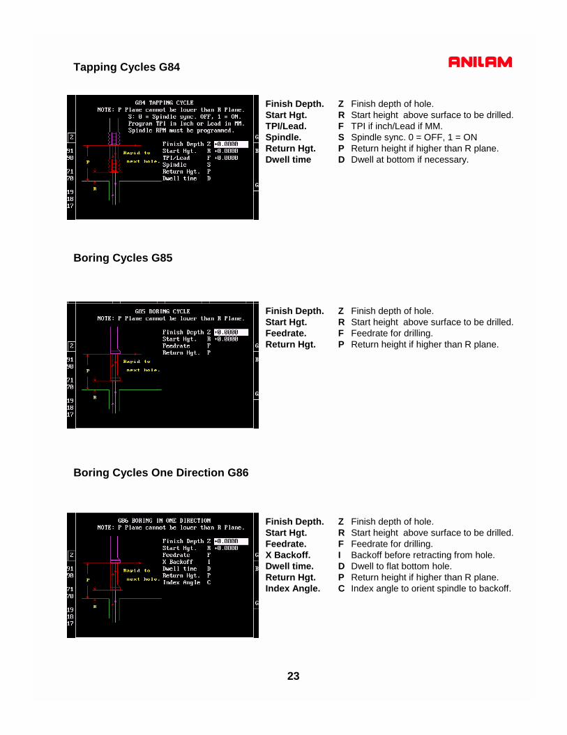
Finish Depth.Start Hgt.Feedrate.X Backoff.Dwell time.Return Hgt.Index Angle.
ZRFIDPC
Finish depth of hole.Start height above surface to be drilled.Feedrate for drilling. Backoff before retracting from hole.Dwell to flat bottom hole.Return height if higher than R plane.Index angle to orient spindle to backoff.
Finish Depth.Start Hgt.Feedrate.Return Hgt.
ZRFP
Finish depth of hole.Start height above surface to be drilled.Feedrate for drilling. Return height if higher than R plane.
Finish Depth.Start Hgt.TPI/Lead.Spindle.Return Hgt.Dwell time
ZRFSPD
Finish depth of hole.Start height above surface to be drilled.TPI if inch/Lead if MM. Spindle sync. 0 = OFF, 1 = ONReturn height if higher than R plane.Dwell at bottom if necessary.
Boring Cycles One Direction G86
Tapping Cycles G84
Boring Cycles G85

24
Flat Bottom Boring Cycle G89
Chip Breaking Cycle G87
Finish Depth.Start Hgt.Feedrate.Dwell.Return Hgt.
ZRFDP
Finish depth of hole.Start height above surface to be drilled.Feedrate for drilling. Dwell in second at bottom of hole.Return height if higher than R plane.
Finish Depth.Start Hgt.Feedrate.First Peck.Delta Peck.Minimum Peck.Chp. Brk. Inc.Retract Depth.Return Hgt.
ZRFIJKWUP
Finish depth of hole.Start height .1 above surface to be drilled.Feedrate for drilling. Amount of first peck.Amount to decrease peck each peck.Smallest peck amount.Retract for chip breakDepth full retract accures.Return height if higher than R plane.

25
Bolt Hole Circle Drilling G79
Hole Pattern Dilling G179
Center.Center.Index Angle.First Angle.Last Angle.Number Holes.Diameter.Radial Path.
XYCABHDR
Center X axis.Center Y axis.Angle to rotate 0 angle from 3 o’cclock. Angle of first hole from 0.Angle of last hole, if full pattern not required.Number of holes to drill.Diameter of pattern.If 1 is entered will move radially around pattern
X Start.Y Start.Angle.X Length.Y WidthNum. Holes X.Num. Holes Y.X Increment.Y Increment.Pat.=0 Sqr.=1
XYCABDEUVW
Start point X axis.Start point Y axis.Angle If pattern is rotated. Distance from first to last hole X axis.Distance from first to last hole Y axis.Number of holes X axis.Number of holes Y axis.Distance between holes X axis.Distance between holes Y axis.Pattern as shown or square around outside.
Use D & E or U & W not both.

26
G-Code without Graphics
Miscellaneous M-Codes
Dwell In seconds with TnExact stop will stop exactly in positiion one shot.Stroke Limit set a box that tool cannot move outside or inside.Reference Point Return sends machine home in designated axis.Reference Point ReturnFixture offset Absolute zero shift from Home.Exact Stop will stop after each move to get into exact position.Contouring Mode continuous path no stops between moves.Macro Call one shot user writen macro.Macro Call modal macro has to be turned off.Cancel Macro cancel modal macro.Preset Zero increamental zero shift canceled by G53 or homing.Feed Per Minute feed in inches per minute.Feed Per Revolution feed in inches per revolution.
Program Stop stop program until START is pressed to to continue.End of Program end of main program.Spindle ON Forward turn spindle ON FORWARD.Spindle ON Reverse turns spindle ON REVERSE.Spindle OFF turns spindle OFF.Coolant ON tuns coolant ON.Coolant OFF turns coolant OFF.Jump to New Program entered using Pxxxx. Call Subroutine call a subroutine using Pxx.End Subroutine Last line of subroutine.Mirror Image axis need to be entered X,Y or Z.M100 turns OFFDry Run All Axis display shows motion but no table movement.Dry Run NO Z Axis X and Y move no Z axis movement.Dry Run OFF turns OFF dry run.

5000M CNC Control
Program Management

2.
INTRODUCTION
The Program Directory provides access to all the program management and disk utilities. These functions include Creating, Selecting, Deleting, Undeleting and Copying programs.The Program Directory also provides access to the Floppy Drive utilities.
Accessing PROGRAM DIRECTORY page.
(1) From the MANUAL mode press: The Program files are listed in alphabetical order.
To access a PROGRAM file from the Program page.
There are 2 methods to access a particular Program File:
(1) Using the keys move the High Light to the desired program and Press:
or
(2) Press the first letter of the desired program name, this will move the High Light to the first program
name with that letter, then use the keys to move the High Light to the desired program
and Press:
To CREATE a new Program.
NOTE: There are 2 methods of creating a program file, both are shown below.
Method No.1 Creating a new program file. From the PROGRAM page:
(1) Press: At the prompt type in the new program name
and Press:
NOTE: Program names can be up to 8 characters in length, but may not include spaces or periods.
Program
Create
Edit
Edit
3.
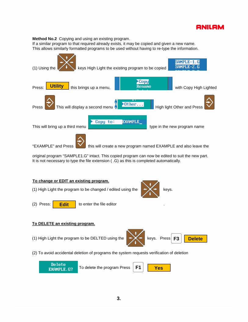
Method No.2 Copying and using an existing program.If a similar program to that required already exists, it may be copied and given a new name. This allows similarly formatted programs to be used without having to re-type the information.
(1) Using the keys High Light the existing program to be copied
Press: this brings up a menu, with Copy High Lighted
Press This will display a second menu High light Other and Press
This will bring up a third menu type in the new program name
“EXAMPLE” and Press this will create a new program named EXAMPLE and also leave the
original program “SAMPLE1.G” intact. This copied program can now be edited to suit the new part.It is not necessary to type the file extension ( .G) as this is completed automatically.
Utility
(1) High Light the program to be changed / edited using the keys.
(2) Press: to enter the file editor .
To DELETE an existing program.
(1) High Light the program to be DELTED using the keys. Press
(2) To avoid accidental deletion of programs the system requests verification of deletion
To delete the program Press
To change or EDIT an existing program.
Edit
F3 Delete
F1 Yes
4.
Utility
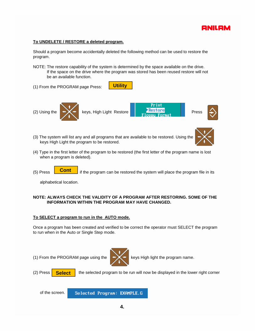
To UNDELETE / RESTORE a deleted program.
Should a program become accidentally deleted the following method can be used to restore the program.
NOTE: The restore capability of the system is determined by the space available on the drive.If the space on the drive where the program was stored has been reused restore will not be an available function.
(1) From the PROGRAM page Press:
(2) Using the keys, High Light Restore Press
(3) The system will list any and all programs that are available to be restored. Using thekeys High Light the program to be restored.
(4) Type in the first letter of the program to be restored (the first letter of the program name is lost when a program is deleted).
(5) Press if the program can be restored the system will place the program file in its
alphabetical location.
NOTE: ALWAYS CHECK THE VALIDITY OF A PROGRAM AFTER RESTORING. SOME OF THE INFORMATION WITHIN THE PROGRAM MAY HAVE CHANGED.
To SELECT a program to run in the AUTO mode.
Once a program has been created and verified to be correct the operator must SELECT the programto run when in the Auto or Single Step mode.
(1) From the PROGRAM page using the keys High light the program name.
(2) Press the selected program to be run will now be displayed in the lower right corner
of the screen.
Cont
Select

5.
To COPY a program to the A: Drive (Floppy Disk).
The 5000M control uses the C:\ drive and the USER directory to store programs within the system. When in the PROGRAM directory the drive and directory are displayed in the lower left corner of the
screen.
The 5000M uses the A:/ drive for the Floppy Disk Drive. Programs may be copied to or copied from the Floppy Drive individually or in multiples.
(1) From the PROGRAM directory use the keys to High light the program to be copied to the
A:\ (Floppy Disk) drive. (Place a floppy disk in the A:\ floppy disk drive unit).
(2) If multiple programs are to be copied High light the first program to be copied using the keys
and Press Then using the keys again High light the next program to be copied and
Press Continue until all programs to be copied are High lighted.
(3) When all programs to be copied are High light Press
(4) With Copy Hi-lited Press
(5) This brings up a menu With A: High lighted Press
The lower left corner of the screen displays COPYING…. while the program is copied. The procedure
is complete when COPYING…. is no longer displayed.
Utility

6.
To COPY a program from the A: Drive (Floppy Disk) to the Program Directory C:\USER
The 5000M uses the A:/ drive for the Floppy Disk Drive. Programs may be copied to or copied from the Floppy Drive individually or in multiples. To view or copy the programs on a Floppy Disk, the operator must first LOG to the Floppy disk Drive (A:\)
(1) From the PROGRAM directory Press (Shift) this will change the descriptions of the F keys,
Press This shows a menu of the drives that the operator can view on screen.
(2) High light A: and Press the programs on the Floppy Dive (A:\) will now
be displayed.
(3) Use the keys to High light the program(s) to be copied to the Program Directory (C:\)
If multiple programs are to be copied High light the first program to be copied using the keys
and Press Then using the keys again High light the next program to be copied and
Press Continue until all programs to be copied are High lighted.
(4) When all programs to be copied are High lighted Press
(5) With Copy High lighted Press A menu is shown
With C: High lighted Press The lower left corner of the screen displays COPYING. while the
program(s) are copied. The procedure is complete when COPYING…. is no longer displayed.
Utility
Log
7.
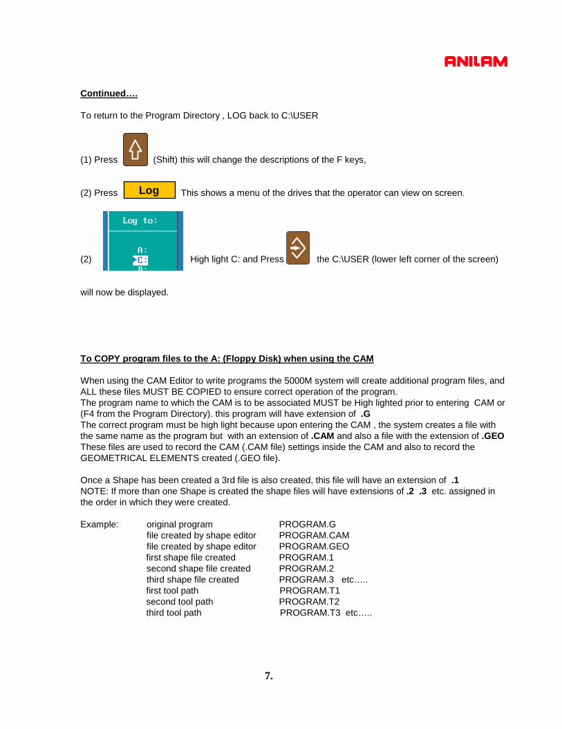
Continued….
To return to the Program Directory , LOG back to C:\USER
(1) Press (Shift) this will change the descriptions of the F keys,
(2) Press This shows a menu of the drives that the operator can view on screen.
(2) High light C: and Press the C:\USER (lower left corner of the screen)
will now be displayed.
To COPY program files to the A: (Floppy Disk) when using the CAM
When using the CAM Editor to write programs the 5000M system will create additional program files, and ALL these files MUST BE COPIED to ensure correct operation of the program. The program name to which the CAM is to be associated MUST be High lighted prior to entering CAM or(F4 from the Program Directory). this program will have extension of .GThe correct program must be high light because upon entering the CAM , the system creates a file with the same name as the program but with an extension of .CAM and also a file with the extension of .GEOThese files are used to record the CAM (.CAM file) settings inside the CAM and also to record the GEOMETRICAL ELEMENTS created (.GEO file).
Once a Shape has been created a 3rd file is also created, this file will have an extension of .1NOTE: If more than one Shape is created the shape files will have extensions of .2 .3 etc. assigned in the order in which they were created.
Example: original program PROGRAM.Gfile created by shape editor PROGRAM.CAMfile created by shape editor PROGRAM.GEOfirst shape file created PROGRAM.1 second shape file created PROGRAM.2third shape file created PROGRAM.3 etc…..first tool path PROGRAM.T1second tool path PROGRAM.T2third tool path PROGRAM.T3 etc…..
Log

8.
To COPY all the program files to the A: (Floppy Disk) when using the CAM continued…..
The 5000M uses the C:/USER drive in the Program Directory. Upon entering the Program Directory the programs displayed will all have an extension of .GTo view all the program files described on the previous page the operator must first LOG to the the root of C:\USER directory (this is where all program files with any extension can be viewed). This is achieved by using wildcard symbols. These symbols are * . * (any program name with any extension).
(1) From the PROGRAM directory Press (Shift) this will change the descriptions of the F keys,
Press This shows a menu of the drives that the operator can view on screen.
(2) High light Other: and Press
(3) At the next menu type *.* Press
(4) Press The screen will now display all programs with all extensions.
Log
* * *
9.
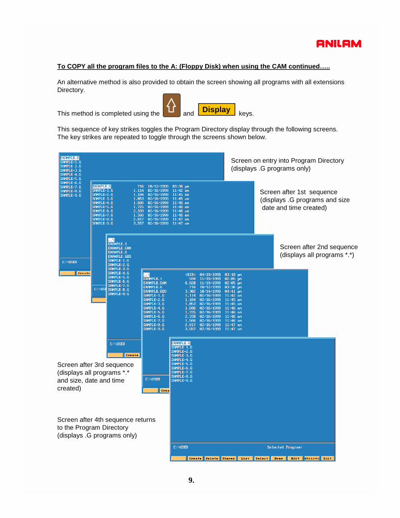
To COPY all the program files to the A: (Floppy Disk) when using the CAM continued…..
An alternative method is also provided to obtain the screen showing all programs with all extensions Directory.
This method is completed using the and keys.
This sequence of key strikes toggles the Program Directory display through the following screens.The key strikes are repeated to toggle through the screens shown below.
Screen on entry into Program Directory(displays .G programs only)
Screen after 1st sequence (displays .G programs and sizedate and time created)
Screen after 2nd sequence(displays all programs *.*)
Screen after 3rd sequence(displays all programs *.*and size, date and timecreated)
Screen after 4th sequence returnsto the Program Directory(displays .G programs only)
Display
10.
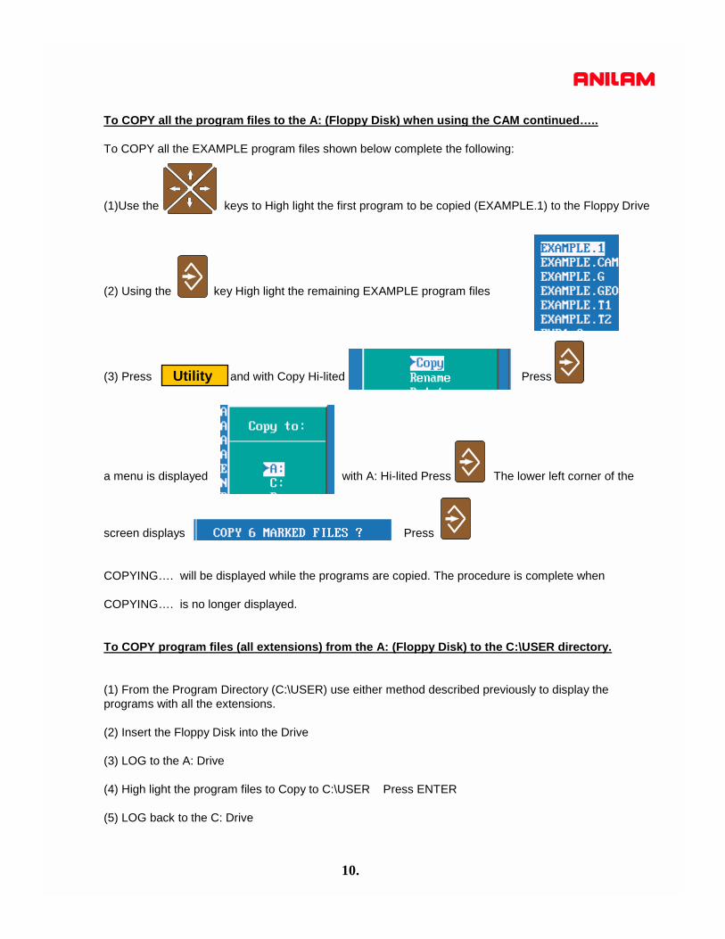
To COPY all the program files to the A: (Floppy Disk) when using the CAM continued…..
To COPY all the EXAMPLE program files shown below complete the following:
(1)Use the keys to High light the first program to be copied (EXAMPLE.1) to the Floppy Drive
(2) Using the key High light the remaining EXAMPLE program files
(3) Press and with Copy Hi-lited Press
a menu is displayed with A: Hi-lited Press The lower left corner of the
screen displays Press
COPYING…. will be displayed while the programs are copied. The procedure is complete when
COPYING…. is no longer displayed.
To COPY program files (all extensions) from the A: (Floppy Disk) to the C:\USER directory.
(1) From the Program Directory (C:\USER) use either method described previously to display the programs with all the extensions.
(2) Insert the Floppy Disk into the Drive
(3) LOG to the A: Drive
(4) High light the program files to Copy to C:\USER Press ENTER
(5) LOG back to the C: Drive
Utility
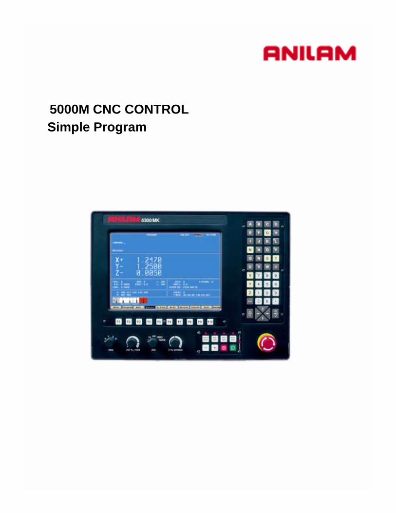
5000M CNC CONTROLSimple Program

1.
CREATING A PROGRAM
From Manual page press F2 PROGRAM
CREATEF2Press
The softkeys will changed as shown below.
Type the program name (Maximum 8 letters/numbers).
Press Enter put into program directory
2.
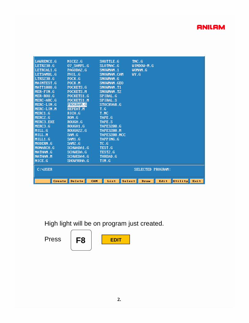
EDIT
High light will be on program just created.
Press F8

3.
This is how screen will appear when entering EDIT
Program name
Note:Softkeys have change .
Note:Insert is turn ON ,if not will not go past bottom of page.

4.
X0 Y0
.75
2.75
.5
1.5
This part needs to have 4 hole drilled .25 dia and .5 deep

5.
Press HELP
High light will be on G0 press enter
Move high light G17 , G70 and G90 press enter on each of these.
F1
Press M5 press
ExitPress it will go into program as shown below.F10

6.
Top line of program.
Program has been edited
Cursor position line and columnLines 2 and 3 are typed in manually.The * allows commence into program control will readignore after it.

7.
Screen will appear as shown below.
Press #2 for basic drilling, press enter.
Press press #9 for DRILL pressHELPF1

8.
Enter values Finish Depth -.5 press down arrow, enterStart Hgt .1 down arrow and Feedrate 12
The next enter hole positions.
Type G0 X.75 Y.5 X2.75 Y1.5 X.75
Type G80
Cancel drill, this must always in program after last hole.
ExitPress exits help menu and enters line into program.F10

9.
Press pressExit Draw
View XY planeView XZ planeView YZ planeView isometric
Fit to screenZoom windowHalf current sizeDouble current sizeScale drawingPans part around screenErase screen
Displays text ----------------Displays tool-----------------Show tool comp-------------Rapid ON/OFF--------------Displays axis----------------Grid ON/OFF----------------Size of grid-------------------Auto/single step/motion---Run ON/OFF----------------Erase screen----------------Block to start draw---------Block to end draw----------
Edit program
Run program
Exit draw mode
F10 F7
Soft key will change as shown below.
Type in last three lines.

10.
Press cursor will be on FIT press enterDISPLAY
This will fits drawing to screen.
Red lines are RAPID moves , blue circle are the holes andpurple circle is the tool.
Press this brings control back to program page
Press to select program ,check that high light is on correct program.
Press go to Manual
Select
Exit
F5
ExitF10
F6
F10

12.
SETTING PART ZERO.
If using an edge finder , touch edge of part using jog keys.
Go to tool page press pressTool OFFSETS
Press this will enter value into table.CalibX
Cursor to required OFFSET using arrow up and down keys.Move X axis until part is located with edge finder.
Because the edge find is .2 dia the position will be incorrect , pressthe letter A key ,a box as shown below will appear. Type in X.1 this will adjust offset to correct position press ENTER.
Repeat for Y axis
All offset are taken from machine Home position.
F9 F1
F4
13.
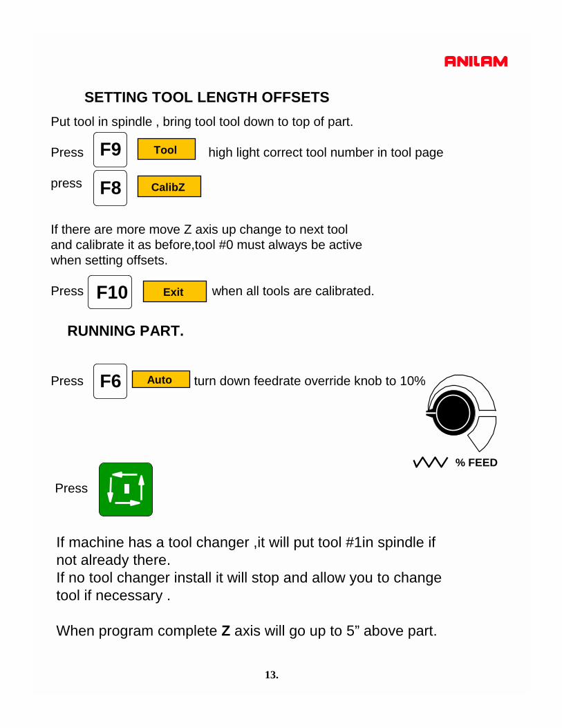
SETTING TOOL LENGTH OFFSETSPut tool in spindle , bring tool tool down to top of part.
Press high light correct tool number in tool page
press
If there are more move Z axis up change to next tooland calibrate it as before,tool #0 must always be activewhen setting offsets.
Press when all tools are calibrated.
Tool
CalibZ
Exit
F9
F8
F10
RUNNING PART.
Press turn down feedrate override knob to 10%Auto
If machine has a tool changer ,it will put tool #1in spindle ifnot already there.If no tool changer install it will stop and allow you to changetool if necessary .
When program complete Z axis will go up to 5” above part.
Press
% FEED
F6

5000M CNC CONTROL GENERATING PROGRAMS USING CAM

STEP BY STEP CREATION OF A PROGRAM USING THE SHAPE EDITOR
The following presentation shows a step by step procedure of how to create a part program using theAnilam 5000 Control. This procedure details the use of the interactive CAM that creates the part profile through simple entry of geometrical elements (points, lines and circles) without having to calculate intersections,tangency points etc. These elements are then connected or “chained” to complete the shape.
Creating the Part Program File in the PROGRAM page.
(1) From the MANUAL mode press:
NOTE: There are 2 methods of creating a program file, both are shown below.
Method No.1 Creating a new program file.
(2) Press: At the prompt type in the program name
and press
NOTE: Program names can be up to 8 characters in length, but may not include spaces or periods.
Method No.2 Copying and using an existing program.If a similar program to that required already exists, it may be copied and given a new name. This allows similarly formatted programs to be used without having to re-type the information.
(2a) Using the keys hi-lite the existing program to be copied
Press: this brings up a menu, with Copy hi-lited
press This will display a second menu Hi-lite Other and press
This will bring up a third menu type in the new program name
“EXAMPLE” and press this will create a new program named EXAMPLE and also leave the
original program “SAMPLE1.G” intact. This copied program can now be edited to suit the new part.It is not necessary to type the file extension ( .G) as this is completed automatically.
Program
Utility
Create
1.

2.
- High light the name the needs the program for, press - The machine program can be coompletely produced in CAM.
CAM
Line tool
Arc tool
Geometry toolCorner radius
Corner chamfer
Chaining tool
When is press, soft keys will change as shown below.
F4- Back Moves curser backwards on a shape.F5- Forw Moves curser forward on a shape.F6- Prev-S Moves curser to previous shape.F7- Next-S Moves curser to next shape.F8- DelMove Deletes last move in shape.F9- DelGeom Deletes geometry, an element number is required.
F1 F2 F3 F4 F5 F6 F7 F8 F9 F10
Press again to turn OFF and return previous funtion keys
Shape
Shape

3.
S-EditPressing the following pop-up menu will appear
Create Create a start point for a shape.Copy Copy a shape to another location.Move Move a shape to anew location.Delete Delete a shape.Rev Arc Reverses direction of an arc in a shape.Project Replaces a radius and joins lines.Join Connects lines together.Import Imports shape from another CAM file.
Pressing the following pop-up menu will appearView
XY planeXZ planeYZ planeIsometric

4.
Pressing the following pop-up menu will appearDisplay
Fit to screen.Zoom in on windowed area.Redraw screenHalf size of screen.Double size of screen.Scale screen.Pan move part around on screen.Erase screen.
List shapes by number.Lists all geometry. Showing coordinates.Recover a deleted shape.Recover a deleted tool path.
Pressing the following pop-up menu will appearMisc
Pressing the following pop-up menu will appearMotion
Generate a tool path around a shape.Generate tool path for pocketing a part.Drilling cycles and paths.Edit any of the above paths.Delete a tool path.

5.
Pressing the following pop-up menu will appearSetup
Parameters for CAM.Turn shapes ON/OFF.Turn geometry ON /OFF.Turn tool paths ON/OFF.Parameters for post.
When high light is on setting press the pop-up menu will appear.
When high light is on paths press the pop-up menu will appear.
Type of dimensioning ABS/INC.Units INCH/MM.Turns Arrows ON/OFF.Turns ON/OFF element labels.Turns Axis marrkers ON/OFF.Turns grid ON/OFF.Size of grid.
Out-put program name.Over write existing program.Out-put type ABS/INC.Unit INCH/MM.Only out-put Axis if it moves.Text on while posting.Program number.Block number.Tool change requirements.Format Number of decimals

6.
2” rad
4”rad
1.8”rad
3.75”
6.25”
X0 Y0
The part below needs to be pocketed.
7.
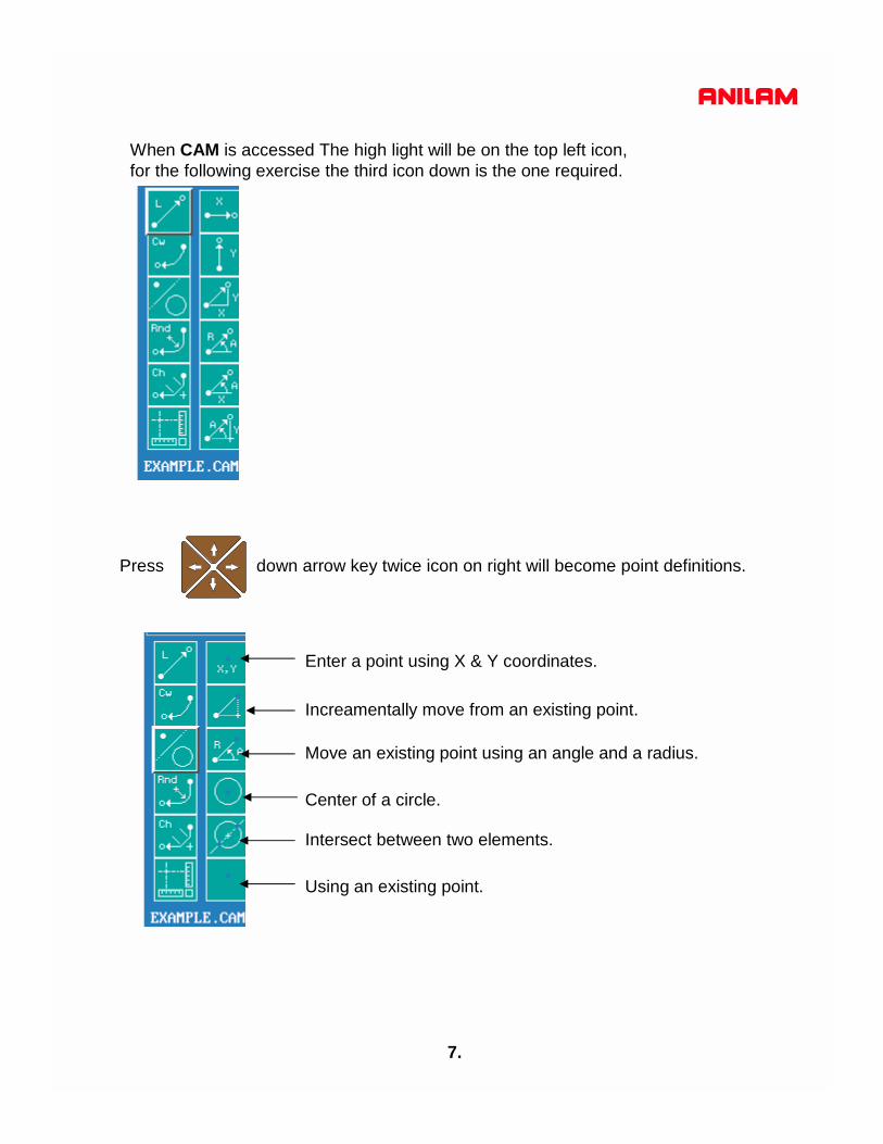
When CAM is accessed The high light will be on the top left icon,for the following exercise the third icon down is the one required.
Press down arrow key twice icon on right will become point definitions.
Enter a point using X & Y coordinates.
Increamentally move from an existing point.
Move an existing point using an angle and a radius.
Center of a circle.
Intersect between two elements.
Using an existing point.
8.
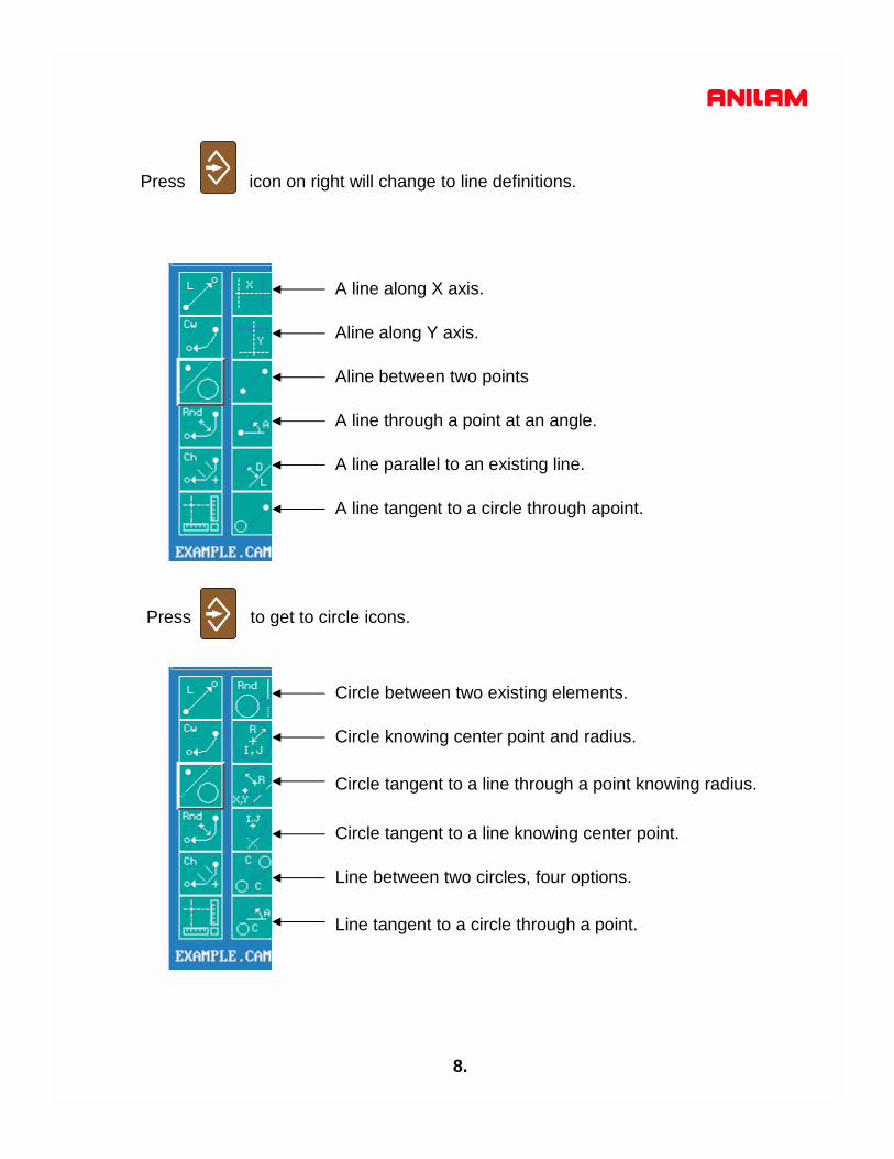
Press icon on right will change to line definitions.
A line along X axis.
Aline along Y axis.
Aline between two points
A line through a point at an angle.
A line parallel to an existing line.
A line tangent to a circle through apoint.
Circle between two existing elements.
Circle knowing center point and radius.
Circle tangent to a line through a point knowing radius.
Circle tangent to a line knowing center point.
Line between two circles, four options.
Line tangent to a circle through a point.
Press to get to circle icons.
9.
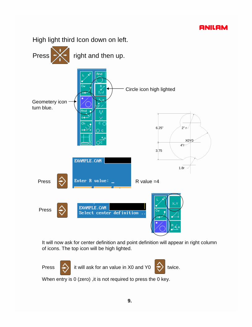
High light third Icon down on left.
Press right and then up.
Geometery iconturn blue.
Circle icon high lighted
Press R value =4
Press
It will now ask for center definition and point definition will appear in right columnof icons. The top icon will be high lighted.
Press it will ask for an value in X0 and Y0 twice.
When entry is 0 (zero) ,it is not required to press the 0 key.
2” r
4”r
1.8r
6.25”
3.75
X0Y0
10.
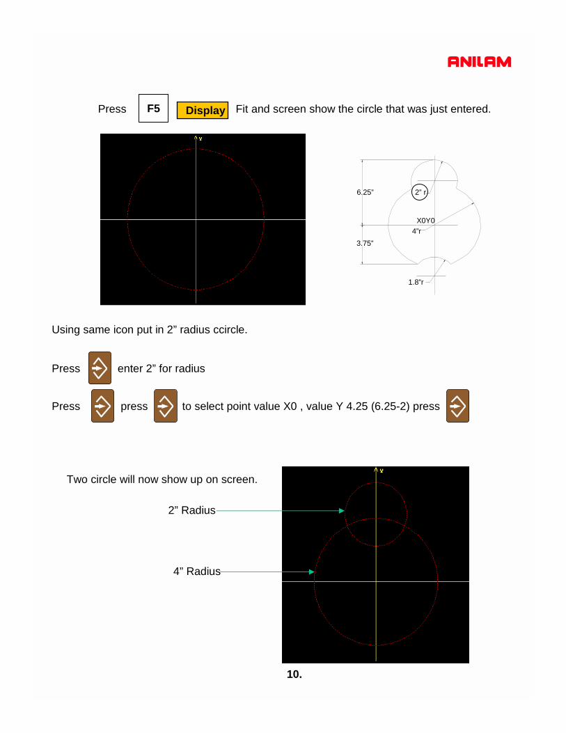
DisplayPress Fit and screen show the circle that was just entered.
Using same icon put in 2” radius ccircle.
2” r
4”r
1.8”r
6.25”
3.75”
Press enter 2” for radius
Press press to select point value X0 , value Y 4.25 (6.25-2) press
Two circle will now show up on screen.
2” Radius
4” Radius
F5
X0Y0

11.
2” r
4”r
1.8r
6.25”
3.75”
The next element required is the 1.8 radius arc.
In order to do this it is necessary put in some constrution geometry.First a line has to be draw at -3.75 in the Y axis.
First high light geometry icon as shown below,
press until line definition appear.
Use arrow keys to get to circled line definition.
Press enter a value of -3.75
X0Y0
12.
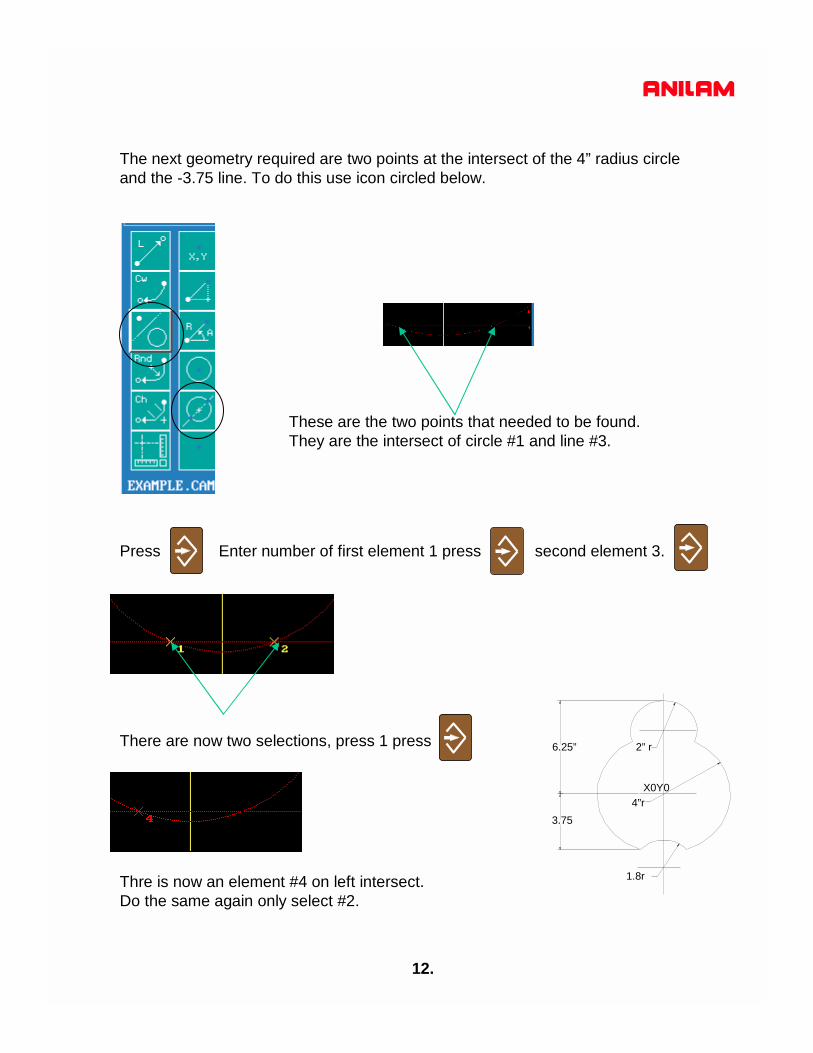
The next geometry required are two points at the intersect of the 4” radius circleand the -3.75 line. To do this use icon circled below.
These are the two points that needed to be found.They are the intersect of circle #1 and line #3.
Press Enter number of first element 1 press second element 3.
There are now two selections, press 1 press 2” r
4”r
1.8r
6.25”
3.75
Thre is now an element #4 on left intersect.Do the same again only select #2.
X0Y0

13.
It is now posible to drive an arc between points #4 & #5.
Use the Icon that allows a circle between two elements.
First question R value. Press
Second question Press
Third question Press
2” r
4”r
1.8r
6.25”
3.75
X0Y0
14.
2” r
4”r
1.8r
6.25”
3.75
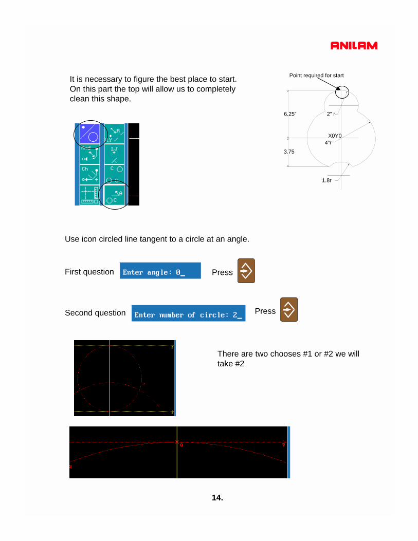
It is necessary to figure the best place to start.On this part the top will allow us to completelyclean this shape.
Use icon circled line tangent to a circle at an angle.
First question Press
Second question Press
There are two chooses #1 or #2 we willtake #2
X0Y0
Point required for start

15.
All the necessary geometry has been established, the next thing is to make a shape, to pocket and contour.
S-EditF3Press
A start point needs to be established for are shape, high light will be onCreate. Create will set where the shape is going to start.
Press select point definition,Use the icon circled.

16.
Press
Press
Enter 8 when it says “From point”
The white number one is the start point for shape #1.
The icon circle is the construction icon,
high light it press it will ask for
an element tobe selected.
Enter -2 press
When selecting circles if cutting in clockwise the number is positive if counter clockwise the number is negative as shown above.
Selected element will show up in green.

17.
The next selection is -1 and there are selection 1 and 2, inthis case 2 is required.
Press 2
Notice that after 2 was selected element #2 when from green to white and element #1 became green.
The next element is #6, this is positive because the direction is clockwise.
Press 6 select #2
press -1 select #2
press-2 select#2
press 8
The shape is now complete press CancelF9
Notice the shape is now outlined in white.

18.
The geometry and shape are complete, the next is to produce atool path to pocket and contour.
MotionPress F7
The first tool path is pocket using arrow keys high light pocket press.
Press

19.
A pop-up window will appear as above.
To enter a value in any of these parameters first press
enter value press
There are two methods of entering tooldiameters, direct just type in value andselect it from toll table.
When More is reached it will bring up anew pop-up window.
Tool table
20.
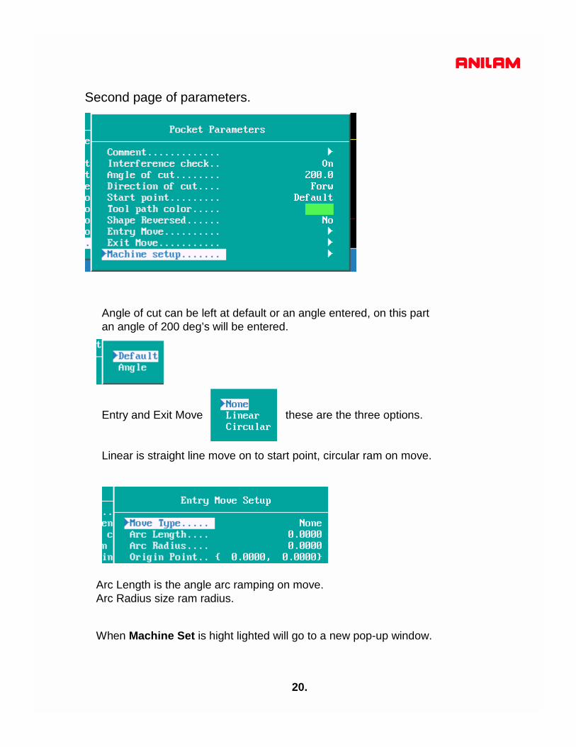
Second page of parameters.
Angle of cut can be left at default or an angle entered, on this partan angle of 200 deg’s will be entered.
Entry and Exit Move these are the three options.
Linear is straight line move on to start point, circular ram on move.
Arc Length is the angle arc ramping on move.Arc Radius size ram radius.
When Machine Set is hight lighted will go to a new pop-up window.

21.
Coolant turn ON at start but not OFF at end as the same tool will be used for pocketing and contouring. The same applies with spindle.
Press ContF10 Press ContF10 Press CalcF8
On the right is how it will appear on screen.Red is geometry.White is the shape outline.Green is tool path.
YesF1

22.
The Contour now need to be done as the edges are still rough.
Press pressMotionF7
It now needs to know which side to put tool comp.
Stepover this is around contour only. Number of passes around contour.
Do this for both Entry and exit moves.
23.
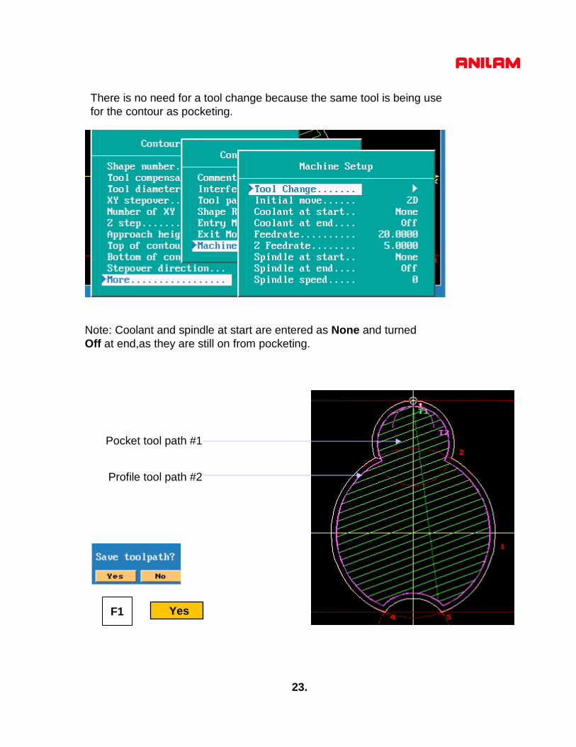
Note: Coolant and spindle at start are entered as None and turnedOff at end,as they are still on from pocketing.
YesF1
Pocket tool path #1
Profile tool path #2
There is no need for a tool change because the same tool is being usefor the contour as pocketing.

24.
Setup F9 Arrow down to post
If machine has a tool changer arrow downto Tool Change press enter arrow down toTool Change Format if M06 is required itshould read as follows T%02DM06.
Block Number are set to start at 10 and increament by 10 this can be changedependinng on your preferance.
Format is set for 8 decimal place change these to 4.
Cont F10 Setup F9Press press
Post F8Press
When finish press it will now return to Program Page.Exit F10

25.
High light EXAMPLE.G press
press fit will be high lighted press
Draw F7
Display F5
XY view Isometic view
All that is left to do is set tool length offsets and fixture offsets,part is ready to run.

26.
If the G-Code Configuration is now correct it can be savefor future use.
Press until top left corner shows
..\ high light EXAMPLE.CAM press high light
will be on Copy press Arrow down to Other Type in
C:\P5M\DEFAULTS.CAM
Display F5
Utility F9

5000M CNC CONTROLDXF Converter
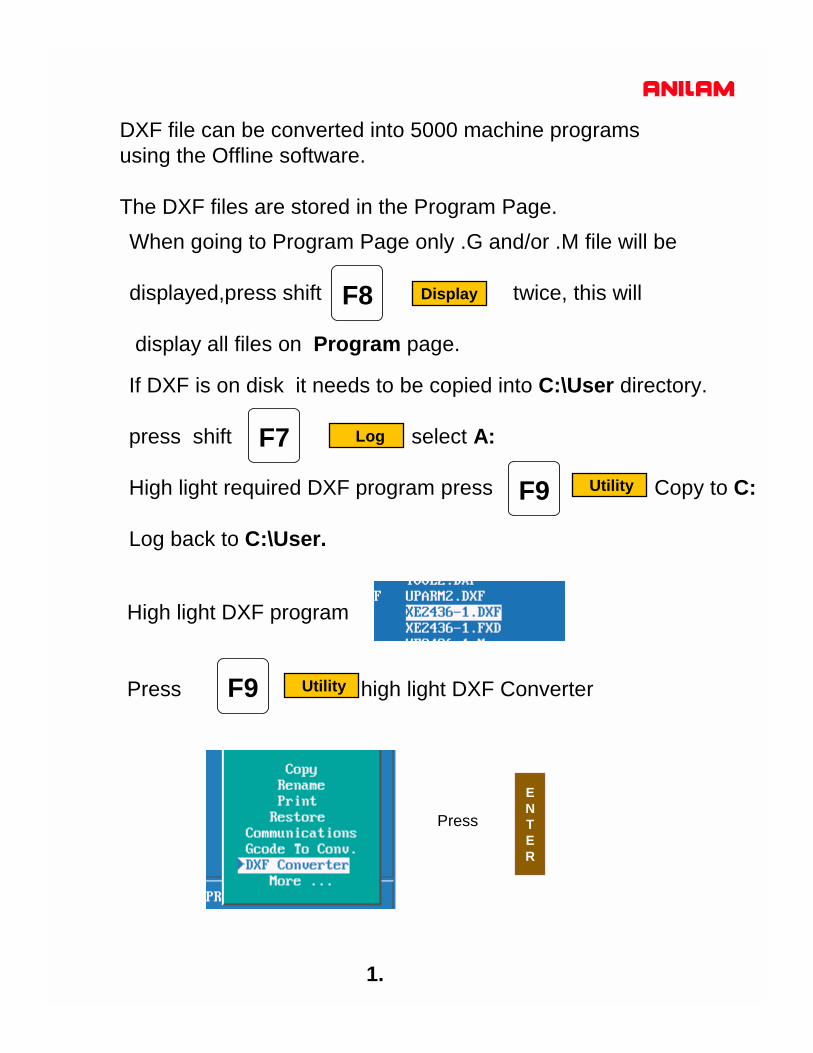
DXF file can be converted into 5000 machine programsusing the Offline software.
The DXF files are stored in the Program Page.When going to Program Page only .G and/or .M file will be
displayed,press shift twice, this will
display all files on Program page.
F8 Display
High light DXF program
Press high light DXF Converter
F7 Log
Press
ENTER
If DXF is on disk it needs to be copied into C:\User directory.
press shift select A:
High light required DXF program press Copy to C:
Log back to C:\User.
F9 Utility
F9 Utility
1.

2.
File name
Select: Used when selecting elements on drawing.Layers: Allows layer on drawing to be turned Off or On.View: XY,XZ,YZ or isometric.Display:Fit, window, redraw, half or double.Save: Saves program with .G once converted.Setup: Allows setup of inputs and outputs.Exit : Goes back to Program page
3.
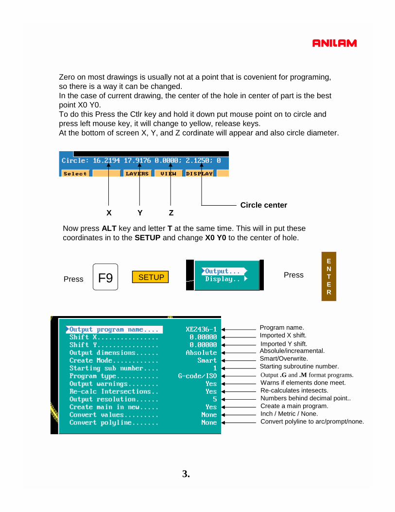
Zero on most drawings is usually not at a point that is covenient for programing,so there is a way it can be changed.In the case of current drawing, the center of the hole in center of part is the bestpoint X0 Y0.To do this Press the Ctlr key and hold it down put mouse point on to circle andpress left mouse key, it will change to yellow, release keys.At the bottom of screen X, Y, and Z cordinate will appear and also circle diameter.
X Y ZCircle center
F9 SETUP Press
ENTER
Now press ALT key and letter T at the same time. This will in put these coordinates in to the SETUP and change X0 Y0 to the center of hole.
Press
Program name.Imported X shift.Imported Y shift.Absolule/increamental.Smart/Overwrite.Starting subroutine number.
Warns if elements done meet.Re-calculates intesects.Numbers behind decimal point..Create a main program.Inch / Metric / None.Convert polyline to arc/prompt/none.
Output .G and .M format programs.

4.
F10 ExitPress
Press ALTkey and letter Fkey at the same time, this will mark the end of eachelement.
F6 Compress
Press high light Window press
A box will appear on screen move around sceen using
press position box as shown below press
ENTER
F5 DISPLAY
ENTER

5.
F1 SelectPress point mouse arrow to lower end of a line as shown
and pess left mouse key. Line will turn green as above and put a number at low end of line, the position of the number is the start point.Now point to the line below it and press left mouse key, all off the line will be come green.
Press ALT key and letter Fkey at the same time the end of line markerswill disappear.
Press press Part will appear at full size on screenF5 DISPLAY
ENTER

6.
F10 ExitPress
F8 SavePress
High light .G or .M file press
F4 Edit
ENTER
Press Y it will now return to Program page.F1Press or

7.
High light .M file press in coversational will appear as belowF8 Edit
Start of program
End of program
Program has to be Edited , to put in tool changes or cutter comp and Z moves.
High light .G file press in G code format will appear as belowF8 Edit
Program has to be Edited , to put in tool changes or cutter comp and Z moves.

8.
This example will show multiple subroutines.
and pick all holes that are the same size , in thiscase 8. When going to second set of holes pressright key on mouse.
F1 SelectPress
The green circle is the last of previously selected holes. The yellowcircle is the one selected with right mouse button and in the bottomleft it is asking if this is a new shape, the answer is Y .It will put a number 2 next to this hole, meaning this is shape 2.

9.
The print below shows the four shapes of the different size holes.
Press F8 Save
F10 ExitPress
1
2 34
5
67 8
1
21 2
1

10.
Below is the output from the DXF converter.Some editing is required to put in drilling cycles.
Subroutine calls
Subroutine for positions of the eight holes numbered in black.
Subroutine for positions of the two holes numbered in green.
Subroutine for positions of the two holes numbered in blue.
Subroutine for positions of the one hole numbered in blue.

The program below is Edited with the drill cycles in the program.
11.

12.
In this example of a full drawing and how to turn off unnecessaryinformation ,such as dimensions etc.

13.
F3 LayersPress
High light Toggle Layers press
ENTER
Put high light on layers not required and press to turn OFF.
ENTER
In the drawing shown the only layer required to be left on is #11
14.
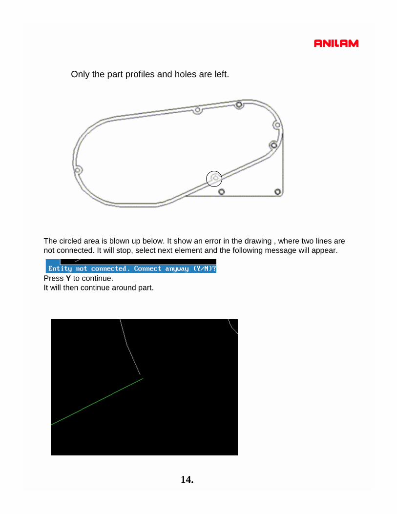
Only the part profiles and holes are left.
The circled area is blown up below. It show an error in the drawing , where two lines arenot connected. It will stop, select next element and the following message will appear.
Press Y to continue.It will then continue around part.