Embed Size (px)
Citation preview

CNC600L Series
PROGRAMMING MANUAL
BNP-B2232C(ENG)

MELDAS is a registered trademark of Mitsubishi Electric Corporation. Other brands and product names throughout this manual are trademarks or registered trademarks of their respective holders.

I
Introduction This instruction manual describes the methods of using the high-performance contour control software-fixed type CNC (NC hereafter) MELDAS 600L Series mainly for a lathe. The programming methods for all of the above models are described, so read this manual thoroughly before starting use. In respect to the functions related to the multi-axis multi-system, the programming and alarm details for each system are the same as the general-purpose (2-axis, 3-axis) lathe. Explanations in this manual assume that all functions are provided with all of the above models. However, all options are not necessarily provided with each CNC, so refer to the specifications issued by the machine manufacturer before starting use. Thoroughly read the "Precautions for Safety" given on the next page to ensure safe use of this numerical control unit. Details described in this manual (1) This manual gives general explanations from the standpoint of the NC side. For explanations concerning individual machine tools, refer to the instruction manual
issued by the machine manufacturer. For items described as "Restrictions, "Usable State", etc., the instruction manual
issued by the machine manufacturer takes precedence over this manual. (2) While every effort has been made to describe special handling in this manual, items
not described in this manual should be interpreted as "Not Possible". (3) The multi-system function is an additional specification. The 3-system model is
explained as an example in this manual, but the number of systems that can be used will differ according to the model.
Note that the maximum number of spindle axes will also differ according to the model. Check the specifications before starting use.
CAUTION
For items described in "Restrictions" or "Usable State", the instruction manual issued by the machine manufacturer takes precedence over this manual.
Items not described in this instruction manual should be interpreted as "Not Possible". This manual has been written on the assumption that all option functions are added.
Refer to the specifications issued by the machine manufacturer before starting use. Refer to the instruction manual issued by the machine manufacturer for explanations on each machine tool.
Some screens and functions may differ or may not be usable depending on the NC system version.

II
Precautions for Safety Always read the specifications issued by the machine manufacturer, this manual, related manuals and attached documents before installation, operation, programming, maintenance or inspection to ensure correct use. Understand this numerical control unit, safety items and cautions before using the unit. This manual ranks the safety precautions into "DANGER", "WARNING" and "CAUTION".
When the user may be subject to imminent fatalities or major injuries if handling is mistaken. When the user may be subject to fatalities or major injuries if handling is mistaken. When the user may be subject to injuries or when physical damage may occur if handling is mistaken.
Note that even items ranked as " CAUTION", may lead to major results depending on the situation. In any case, important information that must always be observed is described.
DANGER
Not applicable in this manual.
WARNING
Not applicable in this manual.
CAUTION
1. Items related to product and manual For items described as "Restrictions" or "Usable State" in this manual, the instruction manual issued by the machine manufacturer takes precedence over this manual.
Items not described in this instruction manual should be interpreted as "Not Possible". This manual is written on the assumption that all option functions are added. Refer to the specifications issued by the machine manufacturer before starting use.
Some screens and functions may differ or may not be usable depending on the NC system version.
DANGER
WARNING
CAUTION

III
CAUTION
2. Items related to programming Because of key chattering etc., during editing, the commands with no value after G become a "G00" operation during running.
";", "EOB" and "%" "EOR" are expressions used for the explanation. The actual codes are "; (line feed)" and "%" for ISO, and "EOB" (End Of Block) and "EOR" (End Of Record) for EIA.
The commands with no value after G become a "G00" operation during running. Always carry out dry run operation before actual machining, and confirm the machining program, tool offset amount and workpiece offset amount, etc.
When creating the machining program, select adequate machining conditions, and make sure not to exceed the machine and NC's performance, capacity and limits. Examples given in this manual do not take the machining conditions into consideration.
Do not change fixed cycle programs without the prior approval of the machine manufacturer.
When programming the multi-system, take special care to the movements of the programs for other systems.
During the spindle synchronous control mode, do not turn the rotation command for the slave spindle OFF while the master spindle and slave spindle are chucked on the same workpiece. This will be hazardous as the slave spindle will stop.
Do not issue another axis name change command before axis name change cancel is issued once axis name change is commanded.

i
CONTENTS 1. CONTROL AXES ..................................................................................................................... 1 1.1 Coordinate Word and Control Axis ................................................................................. 1 1.2 Coordinate Systems and Coordinate Zero Point Symbols ............................................. 2 2. INPUT COMMAND UNITS....................................................................................................... 3 2.1 Input Command Units...................................................................................................... 3 2.2 Input Setting Units ........................................................................................................... 3 3. DATA FORMATS..................................................................................................................... 4 3.1 Tape Codes..................................................................................................................... 4 3.2 Program Formats ............................................................................................................ 6 3.3 Tape Storage Format ...................................................................................................... 8 3.4 Optional Block Skip ......................................................................................................... 8 3.5 Program/Sequence/Block Numbers (O, N)..................................................................... 9 3.6 G Code System............................................................................................................... 10 3.7 Precautions Before Machining ........................................................................................ 14 4. BUFFER REGISTER................................................................................................................ 15 4.1 Pre-read Buffers .............................................................................................................. 15 5. POSITION COMMANDS.......................................................................................................... 16 5.1 Incremental/Absolute Value Commands ........................................................................ 16 5.2 Radius/Diameter Commands.......................................................................................... 18 5.3 Inch/Metric Conversion (G20, G21) ................................................................................ 19 5.4 Decimal Point Input ......................................................................................................... 20 6. INTERPOLATION FUNCTIONS.............................................................................................. 24 6.1 Positioning (Rapid Traverse); G00.................................................................................. 24 6.2 Linear Interpolation; G01................................................................................................. 27 6.3 Circular Interpolation; G02, G03 ..................................................................................... 29 6.4 R-designated Circular Interpolation; G02, G03............................................................... 33 6.5 Plane Selection; G17, G18, G19..................................................................................... 35 6.6 Helical Interpolation; G17, G18, G19, and G02, G03 ..................................................... 37 6.7 Thread Cutting................................................................................................................. 41 6.7.1 Constant lead thread cutting; G33 .......................................................................... 41 6.7.2 Inch thread cutting; G33 .......................................................................................... 45 6.7.3 Continuous thread cutting ....................................................................................... 46 6.7.4 Variable lead thread cutting..................................................................................... 47 6.7.5 Circular thread cutting; G35/G36 ............................................................................ 49 6.8 Milling Interpolation; G12.1/G13.1................................................................................... 55 6.8.1 Selecting milling mode ............................................................................................ 56 6.8.2 Milling interpolation control and command axes..................................................... 57 6.8.3 Selecting a plane during the milling mode .............................................................. 59 6.8.4 Setting milling coordinate system............................................................................ 61 6.8.5 Preparatory functions .............................................................................................. 63 6.8.6 Switching from milling mode to turning mode; G13.1 ............................................. 68 6.8.7 Feed function........................................................................................................... 68 6.8.8 Program support functions ...................................................................................... 68 6.8.9 Miscellaneous functions .......................................................................................... 69 6.8.10 Tool offset functions ................................................................................................ 70 6.8.11 Interference check................................................................................................... 87 7. FEED FUNCTIONS .................................................................................................................. 95 7.1 Rapid Traverse Rate ....................................................................................................... 95 7.2 Cutting Feedrate.............................................................................................................. 95 7.3 Synchronous/Asynchronous Feed; G94, G95 ................................................................ 96 7.4 Feedrate Designation and Effects on Control Axes........................................................ 98

ii
7.5 Thread Cutting Leads...................................................................................................... 102 7.6 Automatic Acceleration/Deceleration .............................................................................. 103 7.7 Rapid Traverse Constant Inclination Acceleration/Deceleration .................................... 104 7.8 Speed Clamp................................................................................................................... 106 7.9 Exact Stop Check; G09................................................................................................... 107 7.10 Exact Stop Check Mode; G61......................................................................................... 111 7.11 Cutting Mode; G64 .......................................................................................................... 111 7.12 Feed Forward Control ..................................................................................................... 112 8. DWELL ..................................................................................................................................... 113 8.1 Dwell Per Second; (G94) G04......................................................................................... 113 8.2 Dwell Per Rotation; (G95) G04 ....................................................................................... 115 9. MISCELLANEOUS FUNCTIONS ............................................................................................ 116 9.1 Miscellaneous Functions (M2-digit BCD)........................................................................ 116 9.2 Miscellaneous Functions (M8-digit) ................................................................................ 118 9.3 2nd Miscellaneous Functions (A8/B8/C8-digit)............................................................... 118 10. SPINDLE FUNCTIONS.......................................................................................................... 119 10.1 Spindle Functions (S2-digit BCD) ................................................................................. 119 10.2 Spindle Functions (S8-digit) .......................................................................................... 119 10.3 Constant Surface Speed Control; G96, G97 ................................................................ 120 10.4 Spindle Clamp Speed Setting; G92 .............................................................................. 127 10.5 Spindle Functions (Multiple Spindles)........................................................................... 129 10.5.1 Multiple-spindle commands................................................................................... 130 10.6 Second Spindle Control Function ................................................................................. 132 10.6.1 Second spindle extension selection...................................................................... 134 11. TOOL FUNCTIONS................................................................................................................ 135 11.1 Tool Functions (T4-digit) ............................................................................................... 135 11.2 Tool Functions (T8-digit) ............................................................................................... 136 11.3 Number of T Command Digits Judgment Function ...................................................... 137 12. TOOL OFFSET FUNCTIONS .............................................................................................. 139 12.1 Tool Offset ................................................................................................................... 139 12.2 Tool Length Offset ....................................................................................................... 141 12.3 Tool Nose Wear Offset ................................................................................................ 143 12.3.1 Wear offset amount hold ..................................................................................... 144 12.4 Nose R Compensation; G40, G41, G42, G46 .............................................................. 145 12.4.1 Tool nose point and compensation directions ..................................................... 147 12.4.2 Nose R compensation operations ....................................................................... 150 12.4.3 Other operations during nose R compensation .................................................. 160 12.4.4 G41/G42 commands and I, J, K designation ...................................................... 168 12.4.5 Interrupts during nose R compensation .............................................................. 173 12.4.6 General precautions for nose R compensation ................................................... 176 12.4.7 Interference check ............................................................................................... 177 12.5 Programmed Tool Offset Input; G10 ............................................................................ 182 12.6 Common System Offset .............................................................................................. 185 13. PROGRAM SUPPORT FUNCTIONS .................................................................................. 186 13.1 Fixed Cycles for Turning ............................................................................................. 186 13.1.1 Longitudinal cutting cycle; G77 ............................................................................. 187 13.1.2 Thread cutting cycle; G78 ..................................................................................... 189 13.1.3 Face cutting cycle; G79......................................................................................... 192 13.2 Compound Fixed Cycles ............................................................................................. 195 13.2.1 Longitudinal rough cutting cycle I; G71................................................................. 196 13.2.2 Face rough cutting cycle I; G72 ............................................................................ 201 13.2.3 Formed material rough cutting cycle; G73............................................................ 206

iii
13.2.4 Finishing cycle; G70 .............................................................................................. 210 13.2.5 Face cut-off cycle; G74 ......................................................................................... 211 13.2.6 Longitudinal cut-off cycle; G75.............................................................................. 213 13.2.7 Compound thread cutting cycle; G76.................................................................... 215 13.2.8 Precautions for compound fixed cycles (G70 to G76) .......................................... 219 13.3 Hole Drilling Fixed Cycles; G80 to G89 ........................................................................ 221 13.3.1 G83 face deep hole drilling cycle 1 (G87 longitudinal deep hole drilling cycle 1)......................................................... 225 13.3.2 G84 face tapping cycle (G88 longitudinal tapping cycle)...................................... 227 13.3.3 G85 face boring cycle (G89 longitudinal boring cycle) ......................................... 232 13.3.4 G80 hole drilling fixed cycle cancel ....................................................................... 232 13.3.5 Precautions for using hole drilling fixed cycles ..................................................... 233 13.4 Deep Hole Drilling Cycle 2; G83.2 ................................................................................ 234 13.5 Subprogram Control; M98, M99.................................................................................... 237 13.6 Variable Commands .................................................................................................... 243 13.7 User Macro.................................................................................................................... 245 13.7.1 User macro commands; G65, G66, G66.1, G67 .................................................. 245 13.7.2 Macro call instruction ........................................................................................... 246 13.7.3 G code for macro................................................................................................... 253 13.7.4 Variables................................................................................................................ 254 13.7.5 Types of variables ................................................................................................. 256 13.7.6 Operation commands............................................................................................ 271 13.7.7 Control commands ................................................................................................ 276 13.7.8 Precautions............................................................................................................ 279 13.8 Double-Turret Mirror Image; G68, G69......................................................................... 281 13.9 Corner Chamfering, Corner Rounding Function I ........................................................ 286 13.9.1 Corner chamfering (,C_)........................................................................................ 286 13.9.2 Corner rounding (,R_) ........................................................................................... 288 13.10 Corner Chamfering, Corner Rounding Function II..................................................... 290 13.10.1 Corner chamfering (,C_)...................................................................................... 290 13.10.2 Corner rounding (,R_) ......................................................................................... 292 13.10.3 Interrupt during corner chamfering/rounding....................................................... 294 13.11 Linear Angle Command ............................................................................................. 295 13.12 Geometric Command ................................................................................................ 296 13.12.1 Geometric command IA .................................................................................... 296 13.13 Program Parameter Input; G10/G11 ......................................................................... 299 13.14 Programmable In-position Check................................................................................ 307 13.15 Positioning (G00)/Machine Coordinate System Selection (G53) Feedrate Designation.................................................................................................................. 310 13.16 Inclined Coordinate Rotation; G173............................................................................ 316 14. COORDINATE SYSTEM SETTING FUNCTIONS ................................................................ 328 14.1 Coordinate Words and Control Axes ............................................................................ 328 14.2 Basic Machine, Workpiece and Local Coordinate Systems......................................... 329 14.3 Machine Zero Point and 2nd Reference Point (Zero Point) ......................................... 330 14.4 Automatic Coordinate System Setting .......................................................................... 331 14.5 Machine Coordinate System Selection; G53................................................................ 332 14.6 Coordinate System Setting; G92 .................................................................................. 333 14.7 Reference Point Return; G28, G29............................................................................... 334 14.8 2nd, 3rd, and 4th Reference (Zero) Point Return; G30 ................................................ 338 14.9 Reference Point Check; G27 ........................................................................................ 341 14.10 Workpiece Coordinate System Setting and Offset; G54 to G59................................... 342 14.11 Local Coordinate System Setting; G52 ......................................................................... 347
iv
15. PROTECTION FUNCTIONS.................................................................................................. 348 15.1 Chuck Barriers/Tailstock Barriers ................................................................................. 348 16. MEASUREMENT SUPPORT FUNCTIONS .......................................................................... 351 16.1 Skip Function; G31........................................................................................................ 351 16.2 Multi-step Skip Function; G31....................................................................................... 356 16.3 Automatic Tool Length Measurement; G37.................................................................. 358 17. MULTI-AXIS, MULTI-SYSTEM COMPOUND CONTROL FUNCTIONS ............................. 361 17.1 Synchronizing Operation between Systems................................................................. 364 17.2 Start Point Designation Synchronizing (Type 1); G115................................................ 369 17.3 Start Point Designation Synchronizing (Type 2); G116................................................ 371 17.4 Balance Cut Command; G15, G14 ............................................................................... 373 17.5 Program Call Control..................................................................................................... 376 17.6 Cross Axis Control; G110.............................................................................................. 377 17.7 Control Axis Synchronization; G125 ............................................................................. 383 17.8 Spindle Synchronization; G114.1, G113....................................................................... 386 17.9 Tool/Spindle Synchronization 1 (Polygon); G114.2, G113........................................... 393 17.10 Tool/Spindle Synchronization 2 (Hobb Machining); G114.3, G113 ............................. 400 17.11 Control Axis Superimposition; G126............................................................................. 411 17.12 Spindle Superimposition; G164, G113 ......................................................................... 426 17.12.1 Relation with other functions ............................................................................. 430 17.12.2 Precautions and restrictions................................................................................ 431 17.13 2-System Simultaneous Thread-cutting Cycle ............................................................. 433 17.13.1 Parameter setting command............................................................................... 433 17.13.2 2-system simultaneous thread-cutting cycle I ..................................................... 434 17.13.3 2-system simultaneous thread-cutting cycle II ................................................... 436 18. OTHER MULTI-AXIS, MULTI-SYSTEM CONTROL FUNCTIONS ...................................... 439 18.1 Miscellaneous Function Output during Axis Movement; G117 .................................... 439 18.2 G Code Macros ............................................................................................................. 441 18.3 Axis Name Change; G111 ............................................................................................ 442 APPENDIX 1 LIST OF FUNCTION CODES............................................................................. 450 APPENDIX 2 LIST OF COMMAND VALUES AND SETTING RANGES................................ 451 APPENDIX 3 CIRCULAR CUTTING RADIUS ERROR ........................................................... 452 APPENDIX 4 STANDARD FIXED CYCLE SUBPROGRAMS................................................. 453 APPENDIX 5 LIST OF VARIABLE NUMBERS........................................................................ 461 APPENDIX 6 CORRESPONDENCE TABLE OF PROGRAM PARAMETER INPUT N NUMBERS........................................................................................... 463 6.1.1 Control parameter........................................................................................................ 464 6.1.2 Axis parameter ............................................................................................................ 466 6.1.3 Setup parameter.......................................................................................................... 467 6.1.4 Setup parameter 2....................................................................................................... 469 6.2.1 Base axis parameter.................................................................................................... 470 6.2.2 Base system parameter .............................................................................................. 471 6.2.3 Base common parameter............................................................................................ 473 6.2.4 Axis specification parameter ....................................................................................... 475 6.2.5 Zero point return parameter ........................................................................................ 476 6.2.6 Absolute position set ................................................................................................... 477 6.2.7 Position switch............................................................................................................. 477 6.2.8 Servo parameter.......................................................................................................... 478 6.2.9 Machine error compensation....................................................................................... 478 6.2.10 Machine compensation data ....................................................................................... 478 6.2.11 Macro list ..................................................................................................................... 479

v
6.2.12 Spindle NC parameter................................................................................................. 484 6.2.13 Spindle parameter ....................................................................................................... 485 6.2.14 Spindle type servo parameter ..................................................................................... 485 6.2.15 PLC constant ............................................................................................................... 486 6.2.16 PLC timer..................................................................................................................... 486 6.2.17 PLC counter................................................................................................................. 486 6.2.18 Bit selection ................................................................................................................. 486 APPENDIX 7 SUPPLEMENTARY DETAILS ON INCOMPLETE THREAD AREAS ARISING DURING THREAD CUTTING............................................................. 487 APPENDIX 8 MACRO INTERFACE EXPANSION................................................................... 491 8.1 Macro Interface Input ...................................................................................................... 492 8.2 Macro Interface Output.................................................................................................... 494 APPENDIX 9 SYSTEM COMMON POSITION INFORMATION RETRIEVING VARIABLES........................................................................................................ 496 APPENDIX 10 LIST OF ALARMS ............................................................................................ 498

1. CONTROL AXES 1.1 Coordinate Word and Control Axis
– 1 –
1. CONTROL AXES 1.1 Coordinate Word and Control Axis
Function and purpose
In the case of a lathe, the axis parallel to the spindle is known as the Z axis and its forward direction is the direction in which the turret moves away from the spindle stock while the axis at right angles to the Z axis is the X axis and its forward direction is the direction in which it moves away from the Z axis, as shown in the figure below.
Spindle stock
Tailstock
Tool
Turret
Coordinate axes and polarities
Since coordinates based on the right hand rule are used with a lathe, the forward direction of the Y axis in the above figure which is at right angles to the X-Z plane is downward. It should be borne in mind that an arc on the X-Z plane is expressed as clockwise or counterclockwise as seen from the forward direction of the Y axis. (Refer to the section on circular interpolation.)
Spindle nose
Machine zero point
Workpiece zero points (G54 to G59)
Local coordinate system(Valid in G54 to G59)
2nd reference point
Reference point
Relationship between coordinates

1. CONTROL AXES1.2 Coordinate Systems and Coordinate Zero Point Symbols
– 2 –
1.2 Coordinate Systems and Coordinate Zero Point Symbols
Function and purpose
Upon completion of the reference point return, the parameters are referred to and automatically set for the basic machine coordinate system and workpiece coordinate systems (G54 to G59). The basic machine coordinate system is set so that the first reference point is at the position designated by the parameter from the basic machine coordinate zero point (machine zero point).
1st reference point
Workpiececoordinatesystem1 (G54)
Workpiececoordinatesystem2 (G55)
Workpiececoordinatesystem5 (G58)
Workpiececoordinatesystem 6 (G59) Z3
Z1
X3
X1
Z2X2
Basic machinecoordinate system
Machine zero point
Hypotheticalmachinecoordinate system(shifted by G92)
The local coordinate system (G52) is valid on the coordinate systems designated by the commands for the workpiece coordinate systems 1 to 6. Using the G92 command, the basic machine coordinate system can be shifted and made the hypothetical machine coordinate system. At the same time, workpiece coordinate systems 1 to 6 are also shifted.
: Reference point
: Machine coordinate zero point
: Workpiece coordinate zero points (G54 to G59)

2. INPUT COMMAND UNITS2.1 Input Command Units
– 3 –
2. INPUT COMMAND UNITS 2.1 Input Command Units
Function and purpose
These are the units used for the movement amounts in the program as commanded by the MDI input. They are expressed in millimeters, inches or degrees (°).
2.2 Input Setting Units
Function and purpose
These are the units of setting data which are used, as with the compensation amounts, in common for all axes.
The input command unit can be selected for each axis and input setting units can be selected in common for the axes by parameters from among the following types. (For further details on settings, refer to the sections about control.)
Linear axis
Millimeter Inch Rotation
axis Type Diametrical command
Radial command
Diametrical command
Radial command
(°)
#1003 cunit=10 0.001 0.001 0.0001 0.0001 0.001 Input
command unit =1 0.0001 0.0001 0.00001 0.00001 0.0001
IS-B 0.0005 0.001 0.0005 0.0001 0.001 Min. movement unit IS-C 0.00005 0.0001 0.00005 0.00001 0.0001
IS-B 0.001 0.001 0.0001 0.0001 0.001 Input setting unit IS-C 0.0001 0.0001 0.00001 0.00001 0.0001
(Note 1) Inch/metric conversion is performed in either of 2 ways: conversion from the
Parameter screen ("Initial inch": valid only when the power is turned ON) and conversion using the G command (G20 or G21).
However, when a G command is used for the conversion, the conversion applies only to the input command units and not to the input setting units.
Consequently, the tool offset amounts and other compensation amounts as well as the variable data should be preset to correspond to input setting unit.
(Note 2) The millimeter and inch systems cannot be used together.

3. DATA FORMATS3.1 Tape Codes
– 4 –
3. DATA FORMATS 3.1 Tape Codes
Function and purpose
The tape command codes used for this NC are combinations of alphabet letters (A, B, C...Z), numbers (0, 1, 2...9) and signs ( +, –, /...). These alphabet letters, numbers and signs are referred to as characters. Each character is represented by a combination of 8 holes which may, or may not, be present. These combinations make up what is called codes. This NC employs the ISO code (R-840).
CAUTION ";", "EOB" and "%" "EOR" are expressions used for the explanation. The actual codes are "line feed" and "%" for ISO.
Detailed description
(1) For the sake of convenience, a ";" has been used in the NC display to indicate End Of
Block (EOB/LF) which separates one block from another. Do not use the ";" key, however, in actual programming but use the keys in the following table instead.
EOB/EOR keys and displays
Code used Key used ISO NC display
End Of Block LF or NL ; End Of Record % %
(Note 1) If a code not given in Table of tape codes is assigned during operation, an Illegal
address error "P32" will result.
(Note 2) The following codes which exist with ISO can be designated by parameter: [ (left square parenthesis) ] (right square parenthesis) # (sharp sign) ∗ (asterisk) = (equals sign) : (colon) ! (exclamation mark) = (queuing code) $ (dollar sign) = (code designating system number)
Any codes which overlap with existing codes or codes which result in parity H cannot be designated.

3. DATA FORMATS3.1 Tape Codes
– 5 –
(2) Significant data section (label skip function) All data up to the first EOB (;), after the power has been turned ON or after operation has been reset, are ignored during automatic operation based on tape, memory loading operation or during a search operation. In other words, the significant data section of a tape extends from the character or number code after the first EOB (;) code after resetting to the point where the reset command is issued.
(3) Control out, control in
When the ISO code is used, all data between control out "(" and control in ")" are ignored by the NC, although these data appear on the setting display unit. Consequently, the command tape name, number and other such data not directly related to control can be inserted in this section. This information will also be loaded, however, during tape loading. The system is set to the "control in" mode when the power is turned ON.
Example of ISOcode
Operator information print-out example
Information in this section is ignored and nothing is executed.
(4) EOR (%) code
Generally, End Of Record is punched at both ends of the tape. It has the following functions: (a) Rewind stop when rewinding tape (with tape handler) (b) Rewind start during tape search (with tape handler) (c) Completion of loading during tape loading

3. DATA FORMATS3.2 Program Formats
– 6 –
3.2 Program Formats
Function and purpose
The prescribed arrangement used when assigning control information to the NC unit is known as the "program format", and the format used with the NC is called the "word address format."
Detailed description
(1) Word and address
A word is a collection of characters arranged in a specific sequence. This entity is used as the unit for processing data and for causing the NC to execute specific operations. Each word used for the NC consists of an alphabet letter and a number of several digits (sometimes with a "+" or "–" sign placed at the head of the number).
Word ------ Numerical (word data) Alphabet (address)
Word configuration
The alphabet letter at the head of the word is the address. It defines the meaning of the numerical information which follows it. With the NC, "S =" can be commanded for a multiple number of spindle commands although this applies only to address S. For details of the types of words and the number of significant digits of numbers used for this NC, refer to Table 1 Format details and abbreviations.
(2) Blocks
A block is a collection of words. It includes the information which is required for the NC to execute one specific operation. One block unit constitutes a complete command. The end of each block is marked with an EOB (End-Of-Block) code.
(3) Programs
A program is a collection of several blocks.
(Note 1) If there is no number after the alphabetic character in the actual program, the value following the alphabetic character will be handled as 0.
(Example) G28XYZ; → G28X0Y0Z0;

3. DATA FORMATS3.2 Program Formats
– 7 –
Table 1 Format details and abbreviations
Item Abbreviation Program number O8 Sequence number N5 Preparatory function G3/G21
Input setting unit A 0.01°, mm X + 62 Z + 62 + 62 Input setting unit B 0.001°, mm X + 53 Z + 53 + 53
Movement command
Input setting unit C 0.0001°, mm X + 44 Z + 44 + 44 Input setting unit A 0.01°, mm I + 62 K + 62 Input setting unit B 0.001°, mm I + 53 K + 53
Movement command, circular, cutter radius
Input setting unit C 0.0001°, mm I + 44 K + 44 Input setting unit A 0.01°, mm X + 53 P8 Input setting unit B 0.001°, mm X + 53 P8
Dwell
Input setting unit C 0.0001°, mm X + 53 P8 Input setting unit A 0.01°, mm F62 (feed per minute)
F43 (feed per rotation) Input setting unit B 0.001°, mm F53 (feed per minute)
F34 (feed per rotation)
Feed function
Input setting unit C 0.0001°, mm F54 (feed per minute) F25 (feed per rotation)
Tool offset T1/T2 Miscellaneous function M2/M8 Spindle function S2/S5/S8 or S = n Tool function T2/T8 2nd miscellaneous function A8/B8/C8 Subprogram P8H5L4
Input setting unit A 0.01°, mm R + 62 Q62 P8 L4 Input setting unit B 0.001°, mm R + 53 Q53 P8 L4
Fixed cycle
Input setting unit C 0.0001°, mm R + 44 Q44 P8 L4
(Note 1) " " denotes the A, B, C, Y, P or R.
(Note 2) The number of digits in the words is checked by the maximum number of digits in the addresses.

3. DATA FORMATS3.3 Tape Storage Format
– 8 –
3.3 Tape Storage Format
Function and purpose
(1) Storage tape and storage sections
The section which is stored into the memory extends from the character following the head EOB after resetting as far as the EOR code. The significant codes listed in Table of tape codes in Section 3.1 are the codes in the above storage section which are actually stored into the memory. All other codes are ignored and are not stored. The data between control out "(" and control in ")" are stored into the memory.
3.4 Optional Block Skip
Function and purpose
This function selectively ignores specific blocks in a machining program which starts with the "/" (slash) code.
Detailed description
(1) Provided that the optional block skip switch is ON, blocks starting with the "/" code are
ignored. They are executed if the switch is OFF. Parity check is valid regardless of whether the optional block skip switch is ON or OFF. When, for instance, all blocks are to be executed for one workpiece but specific blocks are
not to be executed for another workpiece, the same command tape can be used to machine different parts by inserting the "/ " code at the head of those specific blocks.
Precautions for using optional block skip
(1) Put the "/" code at the head of the block. When inserted in a block, this is handled as a
division sign.
(Example) N20G1X25./Z25.; ・・・・・・ NG (This will be handled as 25. /0, so the error P283 "Divided by zero" will occur.)
/N20G1X25.Z25.; ・・・・・・ OK
(2) Parity checks (H and V) are conducted regardless of the optional block skip switch state.
(3) The optional block skip is processed immediately before the pre-read buffer. Consequently, it is not possible to skip up to the block which has been read into the
pre-read buffer.
(4) This function is valid even during a sequence number search.
(5) AII blocks with the "/" code are also input and output during tape storing and tape output, regardless of the state of the optional block skip switch.

3. DATA FORMATS3.5 Program/Sequence/Block Numbers
– 9 –
3.5 Program/Sequence/Block Numbers (O, N)
Function and purpose
These numbers are used for monitoring the execution of the machining programs and for calling both machining programs and specific stages in machining programs. (1) Program numbers are classified by workpiece correspondence or by subprogram units,
and they are designated by the address "O" followed by a number with up to 8 digits.
(2) Sequence numbers are attached where appropriate to command blocks which configure machining programs, and they are designated by the address "N" followed by a number with up to 5 digits.
(3) Block numbers are automatically provided inside the NC itself. They are preset to "0" every time a program number or sequence number is read, and they are counted up one at a time unless program numbers or sequence numbers are commanded in blocks which are subsequently read. Consequently, all the blocks of the machining programs given in the table below can be determined without further consideration by combinations of program numbers, sequence numbers and block numbers.
NC monitor display
NC input machining program Program No.
Sequence No.
Block No.
O12345678 (DEMO.PROG); 12345678 0 0 N100 G00 G90 X120. Z100.; 12345678 100 0 G94 S1000; 12345678 100 1 N102 G71 P210 Q220 I0.2 K0.2 D0.5 F600; 12345678 102 0 N200 G94 S1200 F300; 12345678 200 0 N210 G01 X0 Z95.; 12345678 210 0 G01 X20.; 12345678 210 1 G03 X50. Z80. K–15.; 12345678 210 2 G01 Z55.; 12345678 210 3 G02 X80. Z40. I15.; 12345678 210 4 G01 X100.; 12345678 210 5 G01 Z30.; 12345678 210 6 G02 Z10. K–15.; 12345678 210 7 N220 G01 Z0; 12345678 220 0 N230 G00 X120. Z150.; 12345678 230 0 N240 M02; 12345678 240 0 % 12345678 240 0

3. DATA FORMATS3.6 G Code System
– 10 –
3.6 G Code System
Function and purpose
These numbers are used to monitor the execution status of the machining program, or to call a machining program or a specific process in the machining program. There are 3 G code systems: 1, 2 and 3. Parameters "G code type 1", "G code type 2" and "G code type 3" are used to set the applicable system. G code system 3 is an additional specification. The description of the G functions is based on G code system 2 which serves as the standard.
(Note 1) An alarm results when a G code not listed in the table is commanded. ("P34": Illegal G code)
(Note 2) An alarm results when a G code not included in the additional specifications is commanded.
(Example) An alarm ("P50 No spec: Inch/mm") occurs when the inch command G code (G20) is commanded although the inch/mm specifications have not been provided.
Table of G code systems
G code system (standard = 2) Group Function name
Reference section in
this manual (Section)
1 2 3 G00 G00 G00 01 Positioning 6.1
■ G01 ■ G01 ■ G01 01 Linear interpolation 6.2 G02 G02 G02 01 Circular interpolation (clockwise) 6.3, 6.4 G03 G03 G03 01 Circular interpolation (counterclockwise) 6.3, 6.4 G04 G04 G04 00 Dwell 8.1, 8.2
G09 G09 G09 00 Exact stop 7.8 G10 G10 G10 00 Data setting 12.5 G11 G11 G11 00 Data setting mode cancel 12.1
G12.1 G12.1 G12.1 19 Milling mode ON 6.8
▲ G13.1 ▲ G13.1 ▲ G13.1 19 Milling mode OFF ▲ G14 ▲ G14 ▲ G14 18 Balance cut OFF 17.4
G15 G15 G15 18 Balance cut ON G16 G16 G16 02 Y-Z cylindrical plane selection 6.8
■ G17 ■ G17 ■ G17 02 X-Y plane selection 6.5 ■ G18 ■ G18 ■ G18 02 Z-X plane selection ■ G19 ■ G19 ■ G19 02 Y-Z plane selection ■ G20 ■ G20 ■ G70 06 Inch command ■ G21 ■ G21 ■ G71 06 Metric command
5.3
G22 G22 G22 04 Barrier check ON 15.1 ▲ G23 ▲ G23 ▲ G23 04 Barrier check OFF

3. DATA FORMATS3.6 G Code System
– 11 –
G code system (standard = 2) Group Function name
Reference section in
this manual (Section)
G27 G27 G27 00 Reference point return check 14.9 G28 G28 G28 00 Reference point return 14.7 G29 G29 G29 00 Return from reference point G30 G30 G30 00 2nd reference point return 14.8 G31 G31 G31 00 Skip function 16.1 G32 G33 G33 01 Thread cutting 6.7 G34 G34 G34 01 Variable lead thread cutting G35 G35 G35 01 Circular thread cutting (CW) G36 G36 G36 01 Circular thread cutting (CCW)
G37 G37 G37 00 Automatic tool length offset, automatic tool length measurement
16.3
▲ G40 ▲ G40 ▲ G40 07 Tool nose R compensation cancel 12.4
G41 G41 G41 07 Tool nose R compensation left G42 G42 G42 07 Tool nose R compensation right
■ G43 ■ G43 ■ G43 08 2nd spindle control OFF 10.6 ■ G44 ■ G44 ■ G44 08 2nd spindle control ON
G46 G46 G46 07 Tool nose R compensation (automatic selection of direction) ON
12.4
G50 G92 G92 00 Coordinate system setting Spindle clamp speed setting
14.6 10.4
G52 G52 G52 00 Local coordinate system setting 14.11 G53 G53 G53 00 Machine coordinate system selection 14.5
▲ G54 ▲ G54 ▲ G54 12 Workpiece coordinate system selection 1 14.10 G55 G55 G55 12 Workpiece coordinate system selection 2 G56 G56 G56 12 Workpiece coordinate system selection 3 G57 G57 G57 12 Workpiece coordinate system selection 4 G58 G58 G58 12 Workpiece coordinate system selection 5 G59 G59 G59 12 Workpiece coordinate system selection 6 G61 G61 G61 13 Exact stop check mode 7.9
▲ G64 ▲ G64 ▲ G64 13 Cutting mode 7.10
G65 G65 G65 00 Macro call 13.7.1 G66 G66 G66 14 Macro modal call A G66.1 G66.1 G66.1 14 Macro modal call B
▲ G67 ▲ G67 ▲ G67 14 Macro modal call cancel G68 G68 G68 15 Facing turret mirror image ON 13.8
▲ G69 ▲ G69 ▲ G69 15 Facing turret mirror image OFF
G70 G70 G72 09 Finishing cycle 13.2.4 G71 G71 G73 09 Longitudinal rough cutting cycle 13.2.1 G72 G72 G74 09 Face rough cutting cycle 13.2.2 G73 G73 G75 09 Stock removal in rough cutting cycle 13.2.3

3. DATA FORMATS3.6 G Code System
– 12 –
G code system (standard = 2) Group Function name
Reference section in
this manual (Section)
G74 G74 G76 09 Face cut-off cycle 13.2.5 G75 G75 G77 09 Longitudinal cut-off cycle 13.2.6 G76 G76 G78 09 Compound thread cutting cycle 13.2.7 G76.1 G76.1 G76.1 09 2-system simultaneous thread cutting cycle 1 17.13 G76.2 G76.2 G76.2 09 2-system simultaneous thread cutting cycle 2
▲ G80 ▲ G80 ▲ G80 09 Hole drilling cycle cancel 13.3.4 G83 G83 G83 09 Deep hole drilling cycle 1 (Z axis) 13.3.1 G79 G83.2 G83.2 09 Deep hole drilling cycle 2 13.4 G84 G84 G84 09 Tap cycle (Z axis) 13.3.2 G85 G85 G85 09 Boring cycle (Z axis) 13.3.3 G87 G87 G87 09 Deep hole drilling cycle (X axis) 13.3.1 G88 G88 G88 09 Tap cycle (X axis) 13.3.2 G89 G89 G89 09 Boring cycle (X axis) 13.3.3 G90 G77 G20 09 Longitudinal cutting fixed cycle 13.1.1 G92 G78 G21 09 Thread cutting fixed cycle 13.1.2 G94 G79 G24 09 Face cutting fixed cycle 13.1.3
■ G96 ■ G96 ■ G96 17 Constant surface speed control 10.3 ■ G97 ■ G97 ■ G97 17 Constant surface speed control cancel ■ G98 ■ G94 ■ G94 05 Asynchronous feed 7.3 ■ G99 ■ G95 ■ G95 05 Synchronous feed
– ■ G90 ■ G90 03 Absolute value command – ■ G91 ■ G91 03 Incremental value command
5.1
– ▲ G98 ▲ G98 10 Hole drilling cycle initial return 13.3 – G99 G99 10 Hole drilling cycle reference point return
G110 G110 G110 00 Cross machining command 17.6 G111 G111 G111 00 Axis name change 18.3
G113 G113 G113 00 Spindle synchronization, tool/spindle synchronization cancel
17.8-17.12
G114.1 G114.1 G114.1 00 Spindle synchronization 17.8
G114.2 G114.2 G114.2 00 Tool/spindle synchronization 1 (polygon machining)
17.9
G114.3 G114.3 G114.3 00 Tool/spindle synchronization 2 (hobb machining)
17.10
G115 G115 G115 00 Waiting at designated start point 1 17.2 G116 G116 G116 00 Waiting at designated start point 2 17.3
G117 G117 G117 00 Miscellaneous function output during axis movement
18.1, 18.2
G125 G125 G125 00 Control axis synchronization 17.7 G126 G126 G126 00 Control axis superimposition 17.11 G164 G164 G164 00 Spindle superimposition 17.12 G173 G173 G173 00 Inclined coordinate rotation control 13.16 G200 to G200 to G999 G macro call 18.3

3. DATA FORMATS3.6 G Code System
– 13 –
(Note 1) The " ▲ " mark denotes a G code which is selected within each group when the power is turned ON or when resetting that initializes the modal commands is executed.
(Note 2) The " ■ " mark denotes a G code for which a parameter can be selected as the initial status when the power is turned ON or when resetting that initializes the modal commands is executed. Note that the inch/metric conversion can be made only when the power is turned ON.
CAUTION The commands with "no value after G", will be handled as "G00" during operation.

3. DATA FORMATS3.7 Precautions Before Machining
– 14 –
3.7 Precautions Before Machining
Precautions before machining
CAUTION Before starting actual machining, always carry out dry operation to confirm the machining program, tool offset amount and workpiece offset amount, etc.
When creating the machining program, select the appropriate machining conditions, and make sure that the performance, capacity and limits of the machine and NC are not exceeded. The examples do not consider the machining conditions.

4. BUFFER REGISTER4.1 Pre-read Buffers
– 15 –
4. BUFFER REGISTER 4.1 Pre-read Buffers
Function and purpose
During automatic processing, the contents of 1 block are normally pre-read so that program analysis processing is conducted smoothly. However, during nose R compensation, a maximum of 5 blocks are pre-read for the intersection point calculation including interference check. The specifications of pre-read buffer are as follows: (1) The data of 1 block are stored in this buffer.
(2) Only the significant data in the significant data section are stored into the pre-read buffer.
(3) When codes are sandwiched in the control in or control out mode and the optional block skip function is ON, the data extending from the "/" (slash) code up to the EOB code are not read into the pre-read buffer.
(4) The pre-read buffer contents are cleared with resetting.
(5) When the single block function is ON during continuous operation, the pre-read buffer stores the following block data and then stops operation.
Keyboard
Memory
MDI data
Modeswitching
Max. 5 execution blocks
Pre-readbuffer 5
Buffer 4
Arithmeticprocessing
(Note) Data equivalent to 1 block are stored in 1 pre-read buffer.
Buffer 3
Buffer 2
Buffer 1
Analysis processing

5. POSITION COMMANDS5.1 Incremental/Absolute Value Commands
– 16 –
5. POSITION COMMANDS 5.1 Incremental/Absolute Value Commands
Function and purpose
There are 2 methods of issuing tool movement amount commands: the incremental value command and the absolute value command. The incremental value method applies for coordinates of a point which is to be moved and it issues a command using the distance from the present point, on the other hand, the absolute value method issues a command using the distance from the coordinate zero point. The following figure shows what happens when the tool is moved from point P1 to point P2.
Spindle
Z axis
Coordinate zero point
X axis
Incremental and absolute value commands
The incremental and absolute value commands for the X and Z axes are identified by addresses when control parameter "#6 ABS/INC Addr." is ON and by G codes (G90/G91) when it is OFF. Similarly, even with additional axes (C or Y axis), they are differentiated by addresses, or G code.
Command system Remarks
X axis Address X Z axis Address Z Absolute
value C/Y axis Address C/Y X axis Address U Z axis Address W Incremental
value C/Y axis Address H/V
For setting correspondence between addresses and axes into machine parameters. Absolute and incremental values can be used together in the same block.
(Example)
X_____ W _____ ; Incremental value command for Z axis Absolute value command for X axis
5. POSITION COMMANDS5.1 Incremental/Absolute Value Commands
– 17 –
Precautions
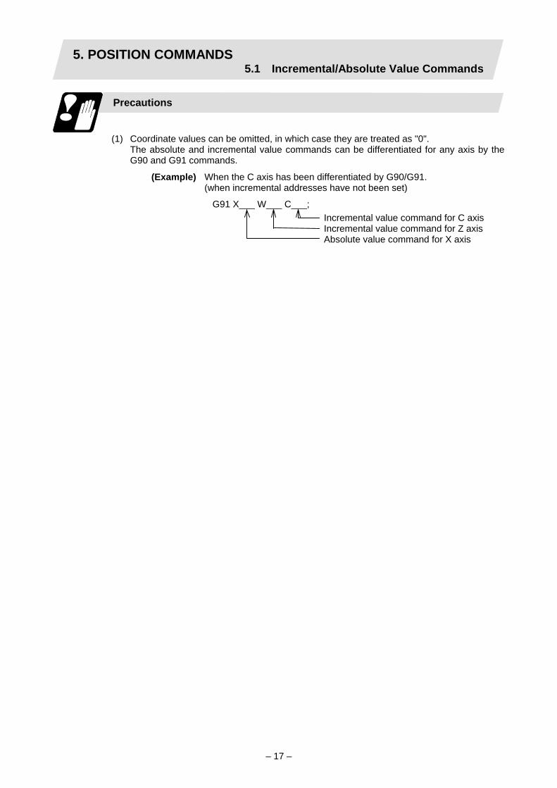
(1) Coordinate values can be omitted, in which case they are treated as "0". The absolute and incremental value commands can be differentiated for any axis by the
G90 and G91 commands.
(Example) When the C axis has been differentiated by G90/G91. (when incremental addresses have not been set)
G91 X___ W___ C___; Incremental value command for C axis Incremental value command for Z axis Absolute value command for X axis

5. POSITION COMMANDS5.2 Radius/Diameter Commands
– 18 –
5.2 Radius/Diameter Commands
Function and purpose
The cross sections of workpieces machined on a lathe are circular, and the diameter or radius value of those circles can be used for movement commands in the X-axis direction. A radius command will move the tool by the commanded amount only, but a diameter command will move the tool both in the X-axis direction by an amount equivalent to one-half the command amount only and in the Z-axis direction by the commanded amount only. This system permits radius or diameter commands to be issued, depending on the parameter setting. The figure below shows the command procedure when the tool is to be moved from point P1 to point P2.
Spindle
Coordinate zero point
Z axis
X axis
r1
r2
X command U command Remarks Radius Diameter Radius Diameter
X = r1 X = 2r1 U = r2 U = 2r2
Even when a diameter command has been selected, only the U command can be made a radius command by parameter.
Radius and diameter commands
Precautions
(1) In the above example, the tool moves from P1 to P2 in the minus direction of the X axis
and so when an incremental value is issued, the minus sign is given to the numerical value being commanded.
(2) In this manual, diameter commands are used in descriptions of both the X and U axes for the sake of convenience.

5. POSITION COMMANDS5.3 Inch/Metric Conversion
– 19 –
5.3 Inch/Metric Conversion (G20, G21)
Function and purpose
These G commands are used to switch between the inch and millimeter (metric) systems.
Command format
G20/G21; G20 Inch command G21 Metric command
Detailed description
The G20 and G21 commands merely select the command units. They do not select the Input units. G20 and G21 selection is meaningful only for linear axes and it is meaningless for rotation axes.
(Example) Relationship between input command units and G20/G21 commands (with
decimal point input type I)
"Initial inch" OFF "Initial inch" ON Input command unit
"cunit" Axis type Command
example G21 G20 G21 G20
Linear axes X100; 0.100mm 0.254mm 0.0039 inch 0.0100 inch 10
Rotation axes C100; 0.100° 0.100° 0.100° 0.100°
Linear axes X100; 0.0100mm 0.0254mm 0.00039 inch 0.00100 inch1
Rotation axes C100; 0.0100° 0.0100° 0.0100° 0.0100°

5. POSITION COMMANDS5.4 Decimal Point Input
– 20 –
5.4 Decimal Point Input
Function and purpose
This function enables the decimal point command to be input. It assigns the zero point in millimeter or inch units for the machining program input information that defines the tool paths, distances and speeds. A parameter selects whether type I (minimum input command unit) or type II (zero point) is to apply for the least significant digit of data without a decimal point.
Command format
. Inch system
. Metric system
Detailed description
(1) The decimal point command is valid for the distances, angles, times and speeds in
machining programs.
(2) Refer to the table "Addresses used and valid/invalid decimal point commands" for details on the valid addresses for the decimal point commands.
(3) The number of significant digits in a decimal point command is shown below (for input command unit CS-B).
Movement command (linear)
Movement command (rotation) Feedrate Dwell (X)
Integer part
Decimal part
Integer part
Decimal part Integer part Decimal part Integer
part Decimal
part 0 to 60000. .000 to .999 MM
(milli- meter)
0 to 99999.
.000 to .999
0 to 99999.
.000 to .999 0 to 999. .0000 to .9999
0. to 99999.
.000 to .999
0 to 2362. .0000 to .9999 INCH (inch)
0 to 9999.
.0000 to .9999
99999. (359.) .0 to .999
0 to 99. .000000 to .999999
0 to 99. .000 to .999
(Note) The top row of Feedrate is for feed per minute and the bottom row is for feed per
rotation. (4) The decimal point command is valid even for commands defining the variable data used
in subprograms, etc.
(5) Decimal point commands for decimal point invalid addresses are processed as integer data only and everything below the decimal point is ignored. Addresses which are invalid for the decimal point are D, H, L, M, N, O, P, S and T. All variable commands, however, are treated as data with decimal points.
Precautions
(1) If an arithmetic operator is inserted, the data will be handled as data with a decimal point.
(Example) G00 X123+0;・・・・・・ This is the X axis 123mm command. It will not be 123µm.

5. POSITION COMMANDS5.4 Decimal Point Input
– 21 –
Example of program
(1) Example of program for decimal point valid address
Decimal point command 1 Specificationdivision
Program example
When 1 = 1µm When 1 = 10µm
Decimal point command 2
1 = 1mm
G0 X123.45 (decimal points are all mm points)
X123.450mm X123.450mm X123.450mm
G0 X12345 X12.345mm (last digit is 1µm unit)
X123.450mm X12345.000mm
#111=123, #112=5.55 X#111 Z#112
X123.000mm, Z5.550mm
X123.000mm, Z5.550mm
X123.000mm, Z5.550mm
#113=#111+#112 (addition) #113 = 128.550 #113 = 128.550 #113 = 128.550
#114=#111–#112 (subtraction) #114 = 117.450 #114 = 117.450 #114 = 117.450
#115=#111∗#112 (multiplication) #115 = 682.650 #115 = 682.650 #115 = 682.650
#116=#111/#112 #117=#112/#111 (division)
#116 = 22.162, #117 = 0.045
#116 = 22.162, #117 = 0.045
#116 = 22.162, #117 = 0.045

5. POSITION COMMANDS5.4 Decimal Point Input
– 22 –
Addresses used and valid/invalid decimal point commands
Add-ress
Decimal point com- mand
Application Re- marks
Valid Coordinate position data Invalid 2nd miscellaneous function
code
Valid Angle data Invalid MRC program number Invalid Data setting, axis number
A
Valid Deep hole drilling cycle (2)Safety distance
Valid Coordinate position data B Invalid 2nd miscellaneous function
code
Valid Coordinate position data Invalid 2nd miscellaneous function
data
Valid Corner chamfering amount ,C
C
Valid Program tool compensation input Nose R compensation amount (incremental)
Valid Automatic tool length measurement, deceleration range d
D
Invalid Data setting, byte type data E Valid Inch threads
Precision thread lead
Valid Feedrate F Valid Thread lead
G Valid Preparatory function code Valid Coordinate position data
Invalid Sequence numbers in subprograms
H
Invalid Data setting, bit type data Valid Circular center coordinates Valid Nose R compensation/tool
radius compensation vector components
I
Valid Deep hole drilling cycle (2)First cut amount
Valid Circular center coordinates Valid Nose R compensation/
nose radius compensation vector components
J
Invalid Deep hole drilling cycle (2)Dwell at return point
(Note 1) Decimal points are all valid in user macro arguments.
Add-ress
Decimal point com- mand
Application Re- marks
Valid Circular center coordinates Valid Nose R compensation/tool
radius compensation vector components
Invalid Hole drilling cycle Number of repetitions
K
Valid Deep hole drilling cycle (2)Second and subsequent cut amounts
Invalid Subprogram Number of repetitions
Invalid Program tool compensation input type selection
L2, L10, L11
Invalid Data setting selection L50
L
Invalid Data setting 2-word type data
4 bytes
M Invalid Miscellaneous function codes
Invalid Sequence numbers N Invalid Data setting, data numbers
O Invalid Program numbers Invalid Dwell time Invalid Subprogram call program
numbers
Invalid 2nd reference point number Invalid Constant surface speed
control, axis number
Invalid MRC finishing shape start sequence number
Valid Cut-off cycle Shift amount/cut amount
Invalid Compound thread cutting cycle, number of cutting passes, chamfering, tool nose angle
Valid Compound thread cutting cycle Thread height
Invalid Program tool compensation input/ Offset number
Invalid Data setting, broad classification number
Invalid Return sequence number from subprogram
P
Valid Coordinate position data

5. POSITION COMMANDS5.4 Decimal Point Input
– 23 –
Add-ress
Decimal point com- mand
Application Re- marks
Invalid Minimum spindle clamp speed
Invalid MRC finishing shape end sequence number
Valid Cut-off cycle Shift amount/cut amount
Valid Compound thread cutting cycle Minimum cut amount
Valid Compound thread cutting cycle First cut amount
Valid Deep hole drilling cycle (1)Cut amount of each pass
Invalid Program tool compensation input Hypothetical tool nose point number
Q
Invalid Deep hole drilling cycle (2)Dwell at cut point
Valid R-designated arc radius Valid Corner rounding circular
radius ,R
Valid Automatic tool length measurement, deceleration range r
Valid MRC longitudinal/face escape amount
Invalid MRC shaping division number
Valid Cut-off cycle, return amount Valid Cut-off cycle, escape
amount
Valid Compound thread cutting cycle, finishing allowance
Valid Compound thread cutting cycle/turning cycle, taper difference
Valid Hole drilling cycle/deep hole drilling cycle (2), distance to reference point
R
Valid Program tool radius compensation input Nose R compensation amount (absolute)
Valid Coordinate position data
Add-ress
Decimal point com- mand
Application Re- marks
Invalid Spindle function codes Invalid Maximum spindle clamp
speed
Invalid Constant surface speed control, surface speed
S
Invalid Data setting, word type data 2 bytesT Invalid Tool function codes
Valid Coordinate position data Invalid 2nd miscellaneous function
codes
U
Valid Program tool compensation input
Valid Coordinate position data Invalid 2nd miscellaneous function
codes
V
Valid Program tool offset input Valid Coordinate position data
Invalid 2nd miscellaneous function codes
W
Valid Program tool compensation input
Valid Coordinate position data Valid Dwell
Invalid 2nd miscellaneous function codes
X
Valid Program tool compensation input
Valid Coordinate position data Invalid 2nd miscellaneous function
codes
Y
Valid Program tool compensation input
Valid Coordinate position data Invalid 2nd miscellaneous function
codes
Z
Valid Program tool compensation input

6. INTERPOLATION FUNCTIONS6.1 Positioning (Rapid Traverse)
– 24 –
6. INTERPOLATION FUNCTIONS 6.1 Positioning (Rapid Traverse); G00
Function and purpose
This command is accompanied by coordinate words. It positions the tool along a linear or non-linear path from the present point as the start point to the end point which is specified by the coordinate words.
Command format
G00 Xx/Uu Zz/Ww;
x, u, z, w Coordinate values
The command addresses are valid for all additional axes.
Detailed description
(1) Once this command has been issued, the G00 mode is retained until it is changed by
another G function or until the G01, G02, G03 or G33 command in the 01 group is issued. If the next command is G00, all that is required is simply that the coordinate words be specified.
(2) In the G00 mode, the tool is always accelerated at the start point of the block and decelerated at the end point. Execution proceeds to the next block after it has been confirmed that the command pulse of the present block is 0 and that the tracking error of the acceleration/deceleration circuit is 0. The in-position width is set by parameter.
(3) Any G function (G83 to G89) in the 09 group is cancelled (G80) by the G00 command.
(4) Whether the tool moves along a linear or non-linear path is determined by parameter, but the positioning time does not change.
(a) Linear path ・・・・・・・・ This is the same as linear interpolation (G01), and the speed is limited by the rapid traverse rate of each axis.
(b) Non-linear path ・・・・ The tool is positioned at the rapid traverse rate independently for each axis.
(5) When no number following the G address, this is treated as G00.
CAUTION The commands with "no value after G" will be handled as "G00" during operation.

6. INTERPOLATION FUNCTIONS6.1 Positioning (Rapid Traverse)
– 25 –
Example of program
Workpiece
Chuck
Turret
Start point (+180, +300)
End point (+100, +150)
(Unit: mm)
G00 X100000 Z150000; Absolute value command G00 U-80000 W-150000; Incremental value command
(With an input setting unit of 0.001mm)
(Note 1) When the "G0 interpolation OFF" user parameter is OFF, the path along which the tool is positioned is the shortest path connecting the start and end points. The positioning speed is automatically calculated so that the shortest distribution time is obtained in order that the commanded speeds for each axis do not exceed the rapid traverse rate.
When, for instance, the X-axis and Z-axis rapid traverse rates are both 9600mm/min, the tool will follow the path in the figure below if the following is programmed:
G00 Z–300000 X400000; (With an input setting unit of 0.001mm)
End point
(Unit: mm)
Start point
Actual X axis rate: 6400mm/min
Actual Z axis rate: 9600mm/min

6. INTERPOLATION FUNCTIONS6.1 Positioning (Rapid Traverse)
– 26 –
(Note 2) When the "G0 interpolation OFF" user parameter is ON, the tool will move along the path from the start point to the end point at the rapid traverse rate of each axis.
When, for instance, the X-axis and Z-axis rapid traverse rates are both 9600mm/min, the tool will follow the path in the figure below if the following is programmed:
G00 Z–300000 X400000; (With an input setting unit of 0.001mm)
End point
Start point
Actual Z axis rate: 9600mm/min
Actual X axis rate: 9600mm/min
(Unit: mm) (Note 3) The rapid traverse rate for each axis with the G00 command differs according to the
individual machine and so refer to the instruction manual issued by machine manufacturer.
(Note 4) Rapid traverse (G00) deceleration check Upon completion of the rapid traverse (G00), execute the next block after the
deceleration check time (Td) has elapsed. The deceleration check time (Td) is as follows, depending on the acceleration/ deceleration type.
Linear acceleration/linear deceleration ・・・・・・・・・・・・・・・・ Td = Ts + α Exponential acceleration/linear deceleration ・・・・・・・・・・・ Td = 2 × Ts + α Exponential acceleration/exponential deceleration ・・・・・・ Td = 2 × Ts + α
Where Ts is the acceleration/deceleration time constant, α = 0 to 14ms The time required for the deceleration check during rapid traverse is the longest
among the rapid traverse deceleration check times of each axis determined by the rapid traverse acceleration/deceleration time constants and by the rapid traverse acceleration/deceleration mode of the axes commanded simultaneously.

6. INTERPOLATION FUNCTIONS6.2 Linear Interpolation
– 27 –
6.2 Linear Interpolation; G01
Function and purpose
This command is accompanied by coordinate words and a feedrate command. It makes the tool move (interpolate) linearly from its present position to the end point specified by the coordinate words at the speed specified by address F. In this case, the feedrate specified by address F always acts as a linear speed in the tool center advance direction.
Command format
G00 Xx/Uu Zz/Ww αα Ff; ("α" is an additional axis)
x, u, z, w, α Coordinate values
Command point
X axis
Present positionZ axis
Detailed description
Once this command is issued, the mode is maintained until another G function (G01, G02, G03, G33) in the 01 group which changes the G01 mode is issued. Therefore, if the next command is also G01 and if the feedrate is the same, all that is required to be done is to specify the coordinate words. If no F command is given in the first G01 command block, program error "P62" results. The feedrate for a rotation axis is commanded by °/min (decimal point position unit). (F300 = 300°/min) The G functions (G70 to G89) in the 09 group are cancelled (G80) by the G01 command.

6. INTERPOLATION FUNCTIONS6.2 Linear Interpolation
– 28 –
Example of program
(Example 1)
X axis
Present position
Z axis
(Unit: mm)
G01 X50.0 Z20.0 F300;
(Example 2) Cutting in the sequence of P1 → P2 → P3 → P4 at 300mm/min feedrate P0 → P1 , P4 → P0 is for tool positioning
Turret
Input setting unit :
(Unit: mm)
G00 X200000 Z40000; P0 → P1 G01 X100000 Z90000 F300; P1 → P2
Z160000; P2 → P3 X140000 Z220000; P3 → P4
G00 X240000 Z230000; P4 → P0

6. INTERPOLATION FUNCTIONS6.3 Circular Interpolation
– 29 –
6.3 Circular Interpolation; G02, G03
Function and purpose
These commands serve to move the tool along a circular.
Command format
G02 (G03) Xx/Uu Zz/Ww Ii Kk Ff;
G02 Clockwise (CW) G03 Counterclockwise (CCW) Xx/Uu Circular end point coordinates, X axis (absolute value of workpiece
coordinate system for X, incremental value from present position for U) Zz/Ww Circular end point coordinates, Z axis (absolute value of workpiece
coordinate system for Z, incremental value from present position for W) Ii Circular center, X axis (for I, radius command/incremental value of X
coordinate at center as seen from start point) Kk Circular center, Z axis (for K, incremental value of Z coordinate at center
as seen from start point) Ff Feedrate
End point
Startpoint
CenterX axis
Z axis

6. INTERPOLATION FUNCTIONS6.3 Circular Interpolation
– 30 –
Detailed description
(1) G02 (or G03) is retained until another G command (G00, G01 or G33) in the 01 group that
changes its mode is issued. The direction of the circular rotation is differentiated by G02 and G03: G02: CW (Clockwise) G03: CCW (Counterclockwise)
Chuck
Work-piece
Turret
Turret
(2) An arc which extends for more than one quadrant can be executed with a single block command.
(3) The following information is needed for circular interpolation.
(a) Rotation direction : Clockwise (G02) or counterclockwise (G03).
(b) Circular end point coordinates : Given by addresses X, Z, U, W.
(c) Circular center coordinates : Given by addresses I, K (incremental value commands).
(d) Feedrate : Given by address F. (4) A program error results when I, K or R is not commanded. Consideration must be given to the sign for I and K since I is the distance in the X-axis
direction to the arc center as seen from the start point and K is the distance in the Z-axis direction.
(5) No T commands can be issued in the G2/G3 modal status. A program error results "P151" if a T command is issued in the G2/G3 modal status.

6. INTERPOLATION FUNCTIONS6.3 Circular Interpolation
– 31 –
Example of program
Coordinatezero point
X axis
Z axis
(Unit: mm)
G2 X120.0 Z70.0 I50.0 F200; Absolute value command G2 U100.0 W-50.0 I50.0 F200; Incremental value command

6. INTERPOLATION FUNCTIONS6.3 Circular Interpolation
– 32 –
(Note 1) The terms "clockwise" (G02) and "counterclockwise" (G03) used for circular operations are defined as a case where in a right-hand coordinate system, the negative direction is viewed from the positive direction of the coordinate axis which is at right angles to the plane in question.
(Note 2) When the end point is the same position as the start point, a 360° circular (full circle) is commanded when the center is commanded using l and K. In this case, always command the end point.
(Note 3) The following occurs when the start and end point radius do not match in a circular command:
(1) Program error "P70" results at the circular start point when error ∆R is greater
than the "G02/G03 Error" parameter value.
G02 Z80. K50.;
Alarm stop
Start point radius End pointradius
Center End pointStartpoint
(2) Spiral interpolation in the direction of the commanded end point results when error ∆R is less than the parameter value.
Start point radius End pointradius
CenterStartpoint
Endpoint
Spiral interpolationG02 Z90. K50.;
Although the parameter setting range is from 0 to 100 (input unit), the parameter values in the above examples are assumed to be extremely high in order to facilitate understanding.
6. INTERPOLATION FUNCTIONS6.4 R-designated Circular Interpolation
– 33 –
6.4 R-designated Circular Interpolation; G02, G03
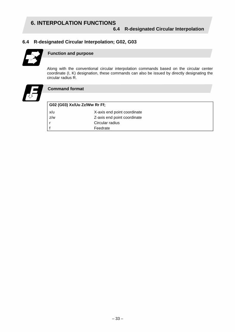
Function and purpose
Along with the conventional circular interpolation commands based on the circular center coordinate (I, K) designation, these commands can also be issued by directly designating the circular radius R.
Command format
G02 (G03) Xx/Uu Zz/Ww Rr Ff;
x/u X-axis end point coordinate z/w Z-axis end point coordinate r Circular radius f Feedrate

6. INTERPOLATION FUNCTIONS6.4 R-designated Circular Interpolation
– 34 –
Detailed description
The circular center is on the bisector line which is perpendicular to the line connecting the start and end points of the circular. The point, where the circular with the specified radius whose start point is the center intersects the perpendicular bisector line, serves as the center coordinates of the circular command. If the R sign of the commanded program is plus, the circular command is smaller than a semicircle, if it is minus, the circular command is larger than a semicircle.
Start point
Center point
Center point
Circular path when R sign is minus
Circular path when R sign is plus
End point
The following condition must be met with an R-designated circular interpolation command: ≤ 1 Where L is the line from the start point to end point. If the above conditions are not satisfied and the arc center cannot be calculated, a program error (P71) will occur. If an R designation and I, K designation are given at the same time in the same block, the circular command with the R designation takes precedence. In the case of a full-circle command (where the start and end points match), an R designation circular command will be completed immediately if it is issued and no operation will result. An I, K designation circular command should therefore be used in such a case.
Example of program
(Example 1)
G03 Zz1 Xx1 Rr1 Ff1; R-designated arc on Z-X plane
(Example 2)
G02 Xx1 Zz1 Ii1 Kk1 Rr1 Ff1; R-designated arc on X-Z plane (When the R designation and I, K designation are contained in the same block, the R designation has priority in processing.)
L 2 × r

6. INTERPOLATION FUNCTIONS6.5 Plane Selection
– 35 –
6.5 Plane Selection; G17, G18, G19
Function and purpose
These commands are used to select the control plane and the plane on which the circular exists. If the 3 basic axes and the parallel axes corresponding to these basic axes are entered as parameters, the commands can select the plane composed of any 2 axes which are not parallel axes. If a rotation axis is entered as a parallel axis, the commands can select the plane containing the rotation axis. These commands are used to select:
• The plane for circular interpolation • The plane for nose R compensation • The plane for milling interpolation
Command format
G17; (I-J plane selection) G18; (K-I plane selection) G19; (J-K plane selection)
I, J and K indicate each basic axis or parallel axis. When the power is turned ON or when the system is reset, the plane set by the control parameters (Initial Z-X plane, Initial Y-Z plane) is selected. If neither of these has been set, the X-Y plane is selected.
G17 (I-J) plane G18 (K-I) plane G19 (J-K) plane

6. INTERPOLATION FUNCTIONS6.5 Plane Selection
– 36 –
Parameter entry
Basic axis Parallel axis I X Y J Y K Z
Plane selection system
This section describes the plane selection for the parameter entry samples shown in Fig. 1.
(1) Axis addresses assigned in the same block as the plane selection (G17, G18, G19)
command determine which of the basic axes or parallel axes are to be in the actual plane selected.
(Example)
G19YZ;G18YZ;G18XZ;
(2) Plane selection is not performed with blocks in which the plane selection G code (G17, G18, G19) is not assigned.
G18X_Z_; Z-X plane Y_Z_; Z-X plane (no plane change)
(3) When the axis addresses are omitted in the block containing the plane selection G codes (G17, G18, G19), it is assumed that the axis addresses of the 3 basic axes have been assigned.
G18; (Z-X plane = G18XZ;)
(4) When the basic axes or their parallel axes are duplicated and assigned in the same block as the plane selection G code (G17, G18, G19), the plane is determined in the order of basic axes, and then parallel axes.
G18XYZ; The Z-X plane is selected. Therefore, the Y movement is unrelated to the selected plane.
(Note 1) When the "#8121 Initial Z-X plane" in the control parameter is kept ON, the G18
plane is selected when the power is turned ON or when the system is reset.
Basic axes and parallel axes can be entered in the parameters. The same axis name can be entered in duplication, but when it is assigned in duplication, the plane is determined by plane selection system (4). It is not possible to set axes, which have not been entered, as control axes.
Fig. 1 Examples of plane selection parameter entry

6. INTERPOLATION FUNCTIONS6.6 Helical interpolation
– 37 –
6.6 Helical interpolation; G17, G18, G19, and G02, G03
Function and purpose
With three orthogonal axes, large diameter screws and solid cams can be machined with simultaneous 3-axis control. With this control, circular interpolation is carried out with two random axes, and at the same time, linear interpolation is carried out with the other axis in synchronization with the circular interpolation.
X
Y
Z
Command format
G17 G02 (G03) Xx/Uu Yy/Vv Zz/Ww Ii Jj Pp Ff;
G17 Arc plane (G17: X-Y plane, G18: Z-X plane, G19: Y-Z plane) (Note 2) G02 (G03) Arc rotation direction (G02: clockwise, G03: counterclockwise) (Note 3)Xx/Uu, Yy/Vv Arc end point coordinates Zz/Ww Linear axis end point Ii, Jj Arc center coordinates Pp Number of pitches Ff Feedrate
(Note 1) In this manual, the following setting descriptions are used. I axis: X, J axis: Y, K axis:
Z
(Note 2) The linear interpolation axis is the other axis not included in the plane selection.
Arc plane Linear interpolation axis G17 X-Y plane Z axis G18 Z-X plane Y axis G19 Y-Z plane X axis
(Note 3) The rotation direction is that looking at the arc plane in the linear interpolation axis'
positive to negative direction.
Command program path
Start point
X-Y plane projected path in command program
End point

6. INTERPOLATION FUNCTIONS6.6 Helical interpolation
– 38 –
Explanation of addresses Add- ress
Address meaning Command range (unit) Remarks
X/U Y/V
Arc end point coordinates
Coordinate command range (mm/inch) (Decimal point command valid)
1. If a value that exceeds the command range is commanded, a program error will occur. (P35 Setting value range over)
2. If an axis other than one which can be controlled with the command system is commanded, a program error will occur. (P33 Format error).
Z/W Linear axis end point coordinates
Coordinate command range (mm/inch) (Decimal point command valid)
1. If a value that exceeds the command range is commanded, a program error will occur. (P35 Setting value range over)
2. If an axis other than one which can be controlled with the command system is commanded, a program error will occur. (P33 Format error).
I J
Arc center coordinates
Coordinate command range (mm/inch) (Decimal point command valid)
1. If a value that exceeds the command range is commanded, a program error will occur. (P35 Setting value range over)
2. If an axis other than one which can be controlled with the command system is commanded, a program error will occur. (P33 Format error).
3. Input a radius value. 4. An arc radius value command (R
command) cannot be used for the arc center coordinates.
P Number of pitches (*)
0 to 99 1. If a value that exceeds the command range is commanded, a program error will occur. (P35 Setting value range over)
2. When omitted, this will be handled as P0. F Feedrate Speed command range
(mm/inch, inch/min) (Decimal point command valid)
1. Command the speed in the direction of each axis' composite element as the feedrate.
2. If a value that exceeds the command range is commanded, a program error will occur. (P35 Setting value range over)
(Example: X-Y plane) * Calculating the pitch (I1)
Z
X
YNumber ofpitches (P1)
End point Command program path
Pitch (l1)
Start point Command program'sX-Y plane projection path
X
Y
pEnd point (xe, ye)
Start point (xs, ys)
θ
l1 = z1/((2π · p1 + θ)/2π) θ = θe – θs = arctan (ye/xe) – arctan (ys/xs) (0 ≤ θ < 2π) Whereas, ys and xs indicate the start point coordinates, ye and xe indicate the end point coordinates, z1 indicates the linear axis end point coordinates, and p1 indicates the number of pitches. θe and θs each indicate the phase difference from the arc center coordinates.

6. INTERPOLATION FUNCTIONS6.6 Helical interpolation
– 39 –
Detailed description
The following type of movement will take place when the following type of command is issued.
G17 G02 Xx Yy Zz Ii Jj Pp Ff;
Z
XY
j
i
z
Number ofpitches p
Endpoint
Command program path
Start point
Command program'sX-Y plane projection path
X
Y
W
j
i
p
End point
Start point
The left drawing shows the process as an exploded view, and the right drawing shows the arc plane from directly above. Using the point designated as the arc center coordinates as the center, the axis starts to rotate at the feedrate f, and after uniformly cutting from the start point to the end point with the number of pitches designated with p, the axis stops.
Example of program
(Example 1)
G17 G02 U0. V0. W150. I-100. J0. P3 F300;
Normal command
Z
XY
150.100.
End point Command program path
Start point
Command program'sX-Y plane projection path
X
Y
p(=3)
Start point
End point
W
100.
The left drawing shows the process as an exploded view, and the right drawing shows the arc plane from directly above. At the start of the block, the axis centers at the point -100mm in the X axis direction and 0mm in the Y axis direction from the workpiece coordinates (start point), and starts cutting at the feedrate 300mm/min while rotating. While carrying out circular interpolation, the axis uniformly cuts three-step pitches while moving 100mm in the Z axis direction, and then stops.

6. INTERPOLATION FUNCTIONS6.6 Helical interpolation
– 40 –
(Example 2)
G17 G02 U-50. V200. W100. I-100. J100. F1500;
When P command is omitted
X
Y
Z
指令プログラム軌跡
終点
始点
指令プログラムのXY平面投影軌跡
100.
Command program’s X-Yplane projection path
Z
XY
100.
Start point
Command programpath
End point
X
Y
Start point
End point
W
I-100.J100.
The left drawing shows the process as an exploded view, and the right drawing shows the arc plane from directly above. At the start of the block, the axis centers at the point -100mm in the X axis direction and 100mm in the Y axis direction from the workpiece coordinates (start point), and starts cutting at the feedrate 1500mm/min while rotating. Since the P command is omitted, the number of pitches is 0. Thus, the axis will cut 100mm in the Z axis direction while carrying out circular interpolation, and then stops.
Precautions and restrictions
(1) When the P designation is omitted, the setting will be the same as P0.
(2) When the arc center coordinates are omitted, "P70 Arc radius error" will occur.
(3) Circular machining is possible by omitting the arc end point coordinates.
(4) If P0 is commanded when the start point and end point coordinates are the same, linear interpolation will take place only in the direction of the linear interpolation axis. If P0 is commanded when the start point and end point coordinates differ, helical interpolation will take place from the start point to end point in one cycle.
(5) A circular interpolation radius command (R command) cannot be issued when carrying out helical interpolation.
(6) If the linear interpolation axis is omitted, the movement will be the same as normal circular interpolation. However, the axis will stop at the end point after carrying out circular interpolation the number of times commanded with P.
(7) If a height axis is set with the same axis designating an arc plane, the latter setting will become valid and normal circular interpolation will take place. However, the circle will be traced only the number of times designated with the P command.
(8) The feedrate is the speed in the direction of each axis' composite element.

6. INTERPOLATION FUNCTIONS6.7 Thread Cutting
– 41 –
6.7 Thread Cutting 6.7.1 Constant lead thread cutting; G33
Function and purpose
The G33 command exercises feed control over the tool which is synchronized with the spindle rotation and so this makes it possible to conduct constant-lead straight thread cutting, tapered thread cutting, and continuous thread cutting.
Straight thread Scrolled thread Continuous thread
Command format
G33 Zz/Ww Xx/Uu Ff Qq ; (Normal lead thread cutting commands)
Zz, Ww, Xx, Uu Thread end point addresses and coordinates Ff Lead of long axis (axis which moves most) direction Qq Thread cutting start shift angle (0.001 to 360.000°)
G33 Zz/Ww Xx/Uu Ee Qq ; (Precision lead thread cutting commands)
Zz, Ww, Xx, Uu Thread end point addresses and coordinates Ee Lead of long axis (axis which moves most) direction Qq Thread cutting start shift angle (0.001 to 360.000°)
δ1δ2
Start point
End point
Z axis
X axis

6. INTERPOLATION FUNCTIONS6.7 Thread Cutting
– 42 –
Detailed description
(1) The E command is also used for the number of threads in inch thread cutting, and
whether the threads or precision lead is to be designated can be selected by parameter setting. (The parameter "#8114 Precision thrd cut E" is set to ON for precision lead designation.)
(2) The lead in the long axis direction is commanded for the tapered thread lead.
Tapered thread section
When a < 45° lead is in Z-axis direction When a > 45° lead is in X-axis direction When a = 45° lead can be in either Z or X-axis direction.
Thread cutting metric input
Input unit system A (0.01mm) B (0.001mm) C (0.0001mm)
Command address F (mm/rev) E (mm/rev) E (threads/
inch) F (mm/rev) E (mm/rev) E (threads/ inch) F (mm/rev) E (mm/rev) E (threads/
inch)
Minimum command unit
1 (= 0.001), (1.=1.000)
1 (= 0.0001), (1.=1.0000)
1 (= 1), (1.=1.0)
1 (= 0.0001),(1.=1.0000)
1 (= 0.00001),(1.=1.00000)
1 (= 1), (1.=1.00)
1 (= 0.00001), (1.=1.00000)
1(=0.000001), (1.=1.000000)
1 (= 1), (1.=1.000)
Command range
0.001 to 9999.999
0.0001 to 9999.9999
0.1 to 9999999.9
0.0001 to 999.9999
0.00001 to 999.99999
0.01 to 999999.99
0.00001 to 99.99999
0.000001 to 99.999999
0.001 to 99999.999
Thread cutting inch input
Input unit system A (0.001inch) B (0.0001inch) C (0.00001inch)
Command address F (inch/rev) E (inch/rev) E (threads/
inch) F (inch/rev) E (inch/rev) E (threads/ inch) F (inch/rev) E (inch/rev) E (threads/
inch)
Minimum command unit
1(=0.00001), (1.=1.00000)
1(=0.000001) (1.=1.000000)
1 (= 1), (1.=1.000)
1(=0.000001),(1.=1.000000)
1(=0.0000001),(1.=1.0000000)
1 (= 1), (1.=1.0000)
1(=0.0000001), (1.=1.0000000)
1(=0.00000001), (1.=1.00000000)
1(=1), (1.=1.00000)
Command range
0.00001 to 999.99999
0.000001 to 99.999999
0.001 to 99999.999
0.000001 to 99.999999
0.0000001 to 9.9999999
0.0001 to 9999.9999
0.0000001 to 9.9999999
0.00000001 to 0.99999999
0.001 to999.99999
(Note 1) It is not possible to assign a lead where the feedrate as converted into feed per
minute exceeds the maximum cutting feedrate.
(3) The constant surface speed control function should not be used for tapered thread cutting commands or scrolled thread cutting commands.
(4) The spindle speed should be kept constant throughout from the rough cutting until the finishing.

6. INTERPOLATION FUNCTIONS6.7 Thread Cutting
– 43 –
(5) If the feed hold function is employed during thread cutting to stop the feed, the thread ridges will lose their shape. For this reason, feed hold does not function during thread cutting.
If the feed hold switch is pressed during thread cutting, block stop will result at the end point of the block following the block in which thread cutting is completed (no longer G33 mode).
(6) The converted cutting feedrate is compared with the cutting feed clamp speed when thread cutting starts, and if it is found to exceed the clamp speed, an operation error will result. (Note 1)
(7) In order to protect the lead during thread cutting, a cutting feedrate which has been converted may sometimes exceed the cutting feed clamp speed.
(8) An illegal lead is normally produced at the start of the thread cutting and at the end of the cutting because of servo system delay and other such factors.
Therefore, it is necessary to command a thread length which is determined by adding the illegal lead lengths δ1 and δ2 to the required thread length.
(9) The spindle speed is subject to the following restriction: 1 ≤ R ≤ Where R ≤ Permissible speed of encoder (r/min) R = Spindle speed (r/min) Thread lead = mm or inches Maximum feedrate = mm/min or inch/mm (this is subject to the restrictions imposed by the machine specifications). (10) Dry run is valid for thread cutting but the feedrate based on dry run is not synchronized
with the spindle rotation. The dry run signal is checked at the start of thread cutting and any switching during
thread cutting is ignored.
(11) Synchronous feed applies for the thread cutting commands even with an asynchronous feed command (G94).
(12) For the spindle override during thread cutting, select either valid or invalid (100% fixed) with the parameters. When the override is valid, the thread will not be cut correctly because of a delay in the servo system if the override is changed during thread cutting. When the override is invalid, the override will change to 100% when operation with an override other than 100% is started. Thus, the thread will not be cut correctly due to a delay in the servo system.
(13) When a thread cutting command is programmed during nose R compensation, the compensation is temporarily canceled and the thread cutting is executed.
(14) When the mode is switched to another automatic mode while G33 is executed, the following block which does not contain a thread cutting command is first executed and then the automatic operation stops.
(15) When the model is switched to the manual mode while G33 is executed, the following block which does not contain a thread cutting command is first executed and then the automatic operation stops. In the case of a single block, the following block which does not contain a thread cutting command is first executed and then the automatic operation stops.
(16) The thread cutting command waits for the single rotation synchronous signal of the rotation encoder and starts movement.
However, movement starts without waiting for this signal when another system issues a thread cutting command during ongoing thread cutting by one particular system. Therefore, thread cutting commands should not be issued by a multiple number of systems.
Maximum feedrateThread lead
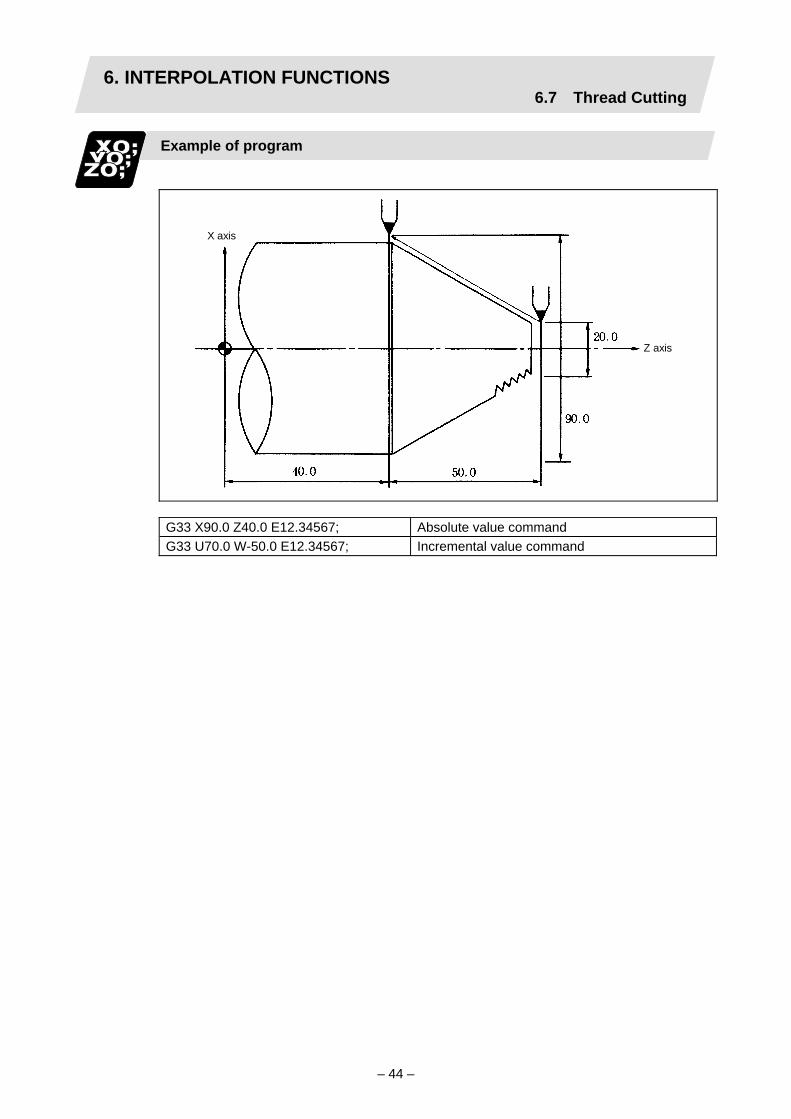
6. INTERPOLATION FUNCTIONS6.7 Thread Cutting
– 44 –
Example of program
X axis
Z axis
G33 X90.0 Z40.0 E12.34567; Absolute value command G33 U70.0 W-50.0 E12.34567; Incremental value command
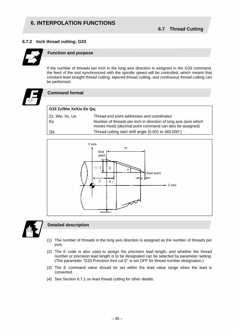
6. INTERPOLATION FUNCTIONS6.7 Thread Cutting
– 45 –
6.7.2 Inch thread cutting; G33
Function and purpose
If the number of threads per inch in the long axis direction is assigned in the G33 command, the feed of the tool synchronized with the spindle speed will be controlled, which means that constant-lead straight thread cutting, tapered thread cutting, and continuous thread cutting can be performed.
Command format
G33 Zz/Ww Xx/Uu Ee Qq;
Zz, Ww, Xx, Uu Thread end point addresses and coordinates Ee Number of threads per inch in direction of long axis (axis which
moves most) (decimal point command can also be assigned) Qq Thread cutting start shift angle (0.001 to 360.000°)
Start point
Endpoint
X axis
Z axis
Detailed description
(1) The number of threads in the long axis direction is assigned as the number of threads per
inch.
(2) The E code is also used to assign the precision lead length, and whether the thread number or precision lead length is to be designated can be selected by parameter setting. (The parameter "G33 Precision thrd cut E" is set OFF for thread number designation.)
(3) The E command value should be set within the lead value range when the lead is converted.
(4) See Section 6.7.1 on lead thread cutting for other details.

6. INTERPOLATION FUNCTIONS6.7 Thread Cutting
– 46 –
Example of program
X axis
Z axis
(Unit: mm)
G33 X90.0 Z40.0 E12.0; Absolute value command G33 U70.0 W-50.0 E12.0; Incremental value command
6.7.3 Continuous thread cutting
Function and purpose
Continuous thread cutting is possible by assigning thread cutting commands continuously. In this way, it is possible to cut special threads whose lead or shape changes.

6. INTERPOLATION FUNCTIONS6.7 Thread Cutting
– 47 –
6.7.4 Variable lead thread cutting
Function and purpose
Variable lead thread cutting is enabled by a command specifying a lead increment or decrement amount per turn of the screw.
Command format
G34 X/U____ Z/W____ F/E____ K____ ;
X/U X coordinate at the end of thread cutting Z/W Z coordinate at the end of thread cutting F/E Standard thread lead K Lead increment or decrement amount per turn of the screw
Non-lead axis
Lead speed
Lead axis

6. INTERPOLATION FUNCTIONS6.7 Thread Cutting
– 48 –
Detailed description
(1) The command range is as shown below.
Thread cutting metric input
Input unit system A (0.01mm) B (0.001mm) C (0.0001mm) A/B/C
Command address F (mm/rev) E (mm/rev) F (mm/rev) E (mm/rev) F (mm/rev) E (mm/rev)
Minimum command unit
1 (=0.001) (1.=1.000)
1 (=0.0001) (1.=1.0000)
1 (=0.0001) (1.=1.0000)
1 (=0.00001)(1.=1.00000)
1 (=0.00001)(1.=1.00000)
1 (=0.000001) (1.=1.000000)
Command range
0.001 to 9999.999
0.0001 to 9999.9999
0.0001 to 999.9999
0.00001 to 999.99999
0.00001 to 99.99999
0.000001 to 99.999999
K (n ∗ mm/rev)n: Number of pitches Same as F or E (signed)
Thread cutting inch input
Input unit system A (0.001inch) B (0.0001inch) C (0.00001inch) A/B/C
Command address F (inch/rev) E (inch/rev) F (inch/rev) E (inch/rev) F (inch/rev) E (inch/rev)
Minimum command unit
1 (=0.00001) (1.=1.00000)
1 (=0.000001) (1.=1.000000)
1 (=0.000001)(1.=1.000000)
1 (=0.0000001)(1.=1.0000000)
1 (=0.0000001)(1.=1.0000000)
1 (=0.00000001) (1.=1.00000000)
Command range
0.00001 to 999.99999
0.000001 to 99.999999
0.000001 to 99.999999
0.0000001 to 9.9999999
0.0000001 to 9.9999999
0.00000001 to 0.99999999
K (n ∗ inch/rev)n: Number of pitches Same as F or E (signed)
(2) A positive value of K indicates incremental pitches. Movement amount of one block (n pitches) = (F + K) + (F + 2K) + (F + 3K) + · · + (F + nK)
(3) A negative value of K indicates decremental pitches. Movement amount of one block (n pitches) = (F – K) + (F – 2K) + (F – 3K) + · · + (F – nK)
(4) A program error will occur if the thread lead is not set correctly.
Error number Meaning Remedy P93 Illegal pitch value
1) An invalid value is specified for F/E or K in a thread cutting command.
2) The last lead goes outside of the F/E command range.
Specify valid values for F/E and K. (Reference 1)
Reference 1) Last lead = √(F2 + 2KZ) Number of pitches = (–F + last lead)/K Z : Length of lead axis
(5) The other matters are the same as G33. Refer to section "6.7.1 Constant lead thread cutting; G33".

6. INTERPOLATION FUNCTIONS6.7 Thread Cutting
– 49 –
6.7.5 Circular thread cutting; G35/G36
Function and purpose
Circular thread cutting is carried out by applying circular interpolation while feeding the tool in synchronization with the spindle rotation.
F/E: Long axis direction lead
F/E
Thread cutting tool
Workpiece center

6. INTERPOLATION FUNCTIONS6.7 Thread Cutting
– 50 –
Command format
G35/G36 Xx/Uu Zz/Ww Ii Kk
Rr Ff/Ee Qq ;
G35 Clockwise (CW) G36 Counterclockwise (CCW) Xx/Uu X axis circular end point coordinate (X: absolute value for workpiece
coordinate system, U: incremental value from current position) Zz/Ww Z axis circular end point coordinate (Z: absolute value for workpiece
coordinate system, W: incremental value from current position) Ii X axis circular center coordinate (incremental value of circular center
looking from start point) Kk Z axis circular center coordinate (incremental value of circular center
looking from start point) Rr Circular radius Ff/Ee Lead of long axis (axis with longest movement amount) direction
(Ff … Normal lead thread/Ee … Precision lead thread or inch thread) Qq Thread cutting start shift angle (0.001 to 360.000°)
Start point
End point
R I
K
Center
WZ
U/2
X
X axis
Z axis
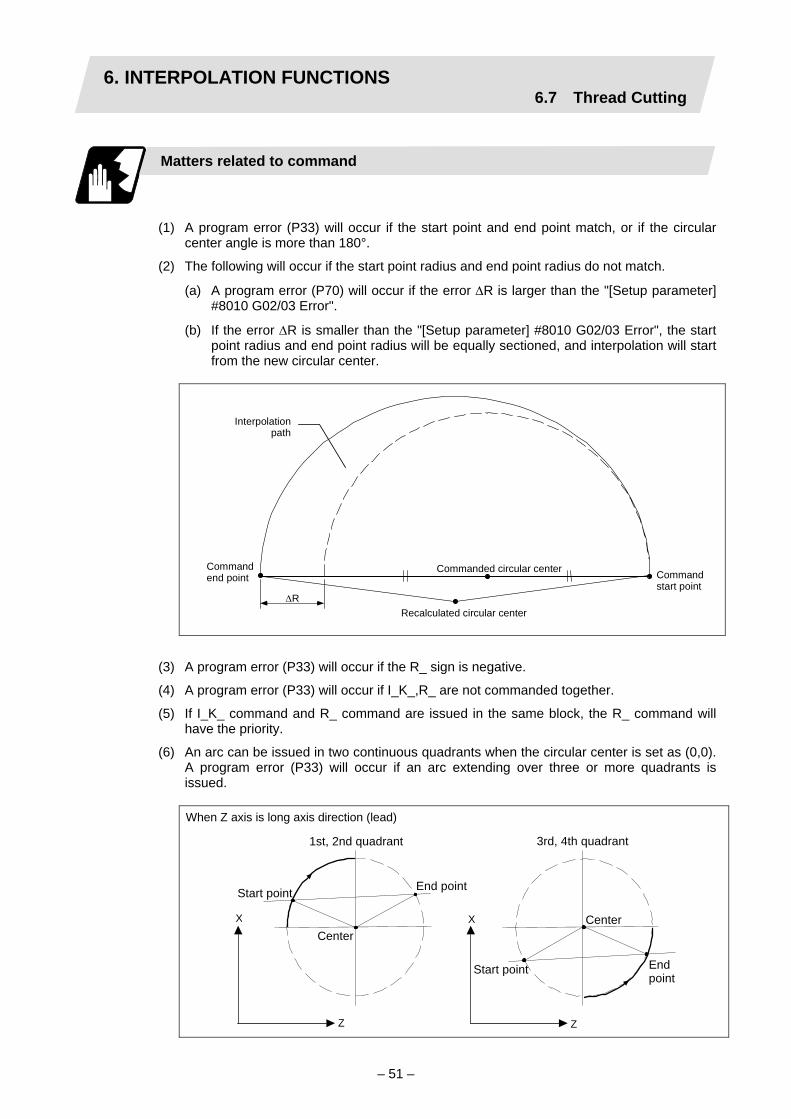
6. INTERPOLATION FUNCTIONS6.7 Thread Cutting
– 51 –
Matters related to command
(1) A program error (P33) will occur if the start point and end point match, or if the circular center angle is more than 180°.
(2) The following will occur if the start point radius and end point radius do not match.
(a) A program error (P70) will occur if the error ∆R is larger than the "[Setup parameter] #8010 G02/03 Error".
(b) If the error ∆R is smaller than the "[Setup parameter] #8010 G02/03 Error", the start point radius and end point radius will be equally sectioned, and interpolation will start from the new circular center.
Interpolation
path
Command end point
Commanded circular center Command start point
Recalculated circular center ∆R
(3) A program error (P33) will occur if the R_ sign is negative.
(4) A program error (P33) will occur if I_K_,R_ are not commanded together.
(5) If I_K_ command and R_ command are issued in the same block, the R_ command will have the priority.
(6) An arc can be issued in two continuous quadrants when the circular center is set as (0,0). A program error (P33) will occur if an arc extending over three or more quadrants is issued.
When Z axis is long axis direction (lead)
X
Z
1st, 2nd quadrant
X
Z
3rd, 4th quadrant
Center
Start point End point
Center
Start point End point

6. INTERPOLATION FUNCTIONS6.7 Thread Cutting
– 52 –
(7) If the vertical axis and horizontal axis command movement amount is the same, the horizontal axis direction in the selected plane will be the long axis.
Plane selection Long axis when movement amount is the same
G17 : (IJ plane) I axis G18 : (KI plane) K axis G19 : (JK plane) J axis
Matters related to speed
(1) If "cutting feedrate > clamp speed (thread cutting clamp speed)" when thread cutting is started, the "M01 operation error 0107" will occur and thread cutting will not start. The lead axis and non-lead axis feedrate is checked in the following manner.
(a) Lead axis .................. Checked with the spindle rotation speed and commanded pitch when thread cutting starts.
(b) Non-lead axis............ Feedrate of the section with the largest movement per unit time between the circular start point and end point is checked at the start of thread cutting.
(2) The cutting feedrate may exceed the clamp speed to guarantee the lead during thread cutting. In this case, "M01 operation error 0107" will appear, but thread cutting will continue. Note that only when the circular thread command is successively commanded, if the cutting feedrate exceeds the clamp speed during thread cutting, the automatic operation will stop just before the circular thread command, and "M01 operation error 0107" will appear.
(3) Related parameters • #2002 clamp (cutting feed clamp speed) • #2044 thr_clamp (thread cutting clamp speed)
Matters related to continuous thread cutting
(1) Continuous thread cutting is possible by successively commanding the thread cutting command. This makes it possible to cut a lead midway or to cut a special thread having a changing shape.
(2) Continuous thread cutting is possible as arc → arc, arc → constant lead, constant lead → constant lead, constant lead → arc.
Matters related to servo system delay
(1) Illegal leads will result at the start and end of thread cutting due to normal servo system
delay, etc. Thus, command the length including the illegal lead length at the start and end of thread cutting to the required thread length. Another method is to command the required thread length with the circular thread, and command the illegal lead length before and after (start and end of thread cutting) as a uniform lead thread (G33). (Continuous thread cutting with constant lead → arc → constant lead.)

6. INTERPOLATION FUNCTIONS6.7 Thread Cutting
– 53 –
Relation with other functions
(1) Coordinate system
(a) A program error (P113) will occur if a circular thread command is used for an orthogonal axis in the selected plane.
(2) Program test (a) The thread cutting feedrate is not synchronized with the spindle rotation when dry run
is valid. (The thread pitch is not guaranteed.) (b) The dry run signal input during thread cutting is invalid. (c) The thread cutting feedrate is not synchronized with the spindle rotation during
program check. (The thread pitch is not guaranteed.) The circular thread is a reverse run prohibit command, so reverse run is not possible.
(3) Calling, starting and stopping the program (a) Feed hold cannot be applied during thread cutting. If the feed hold switch is pressed
during thread cutting, block stop will result at the end point of the block following the block in which thread cutting is completed (no longer thread cutting mode).
(4) Functions for supporting machining methods (a) Circular thread cutting will function correctly even during mirror image. (b) Circular thread cutting will function correctly even during cross. (c) The "M01 operation error 1003" will occur if the circular thread command is used
during superimposition control. (d) A program error (P201) will occur of there is a circular thread command in the
finished shape program while using the compound lathe fixed cycle. (e) A program error (P385) will occur if a corner R/C is commanded during thread cutting
or in the next block's thread cutting. (f) The geometric function cannot be used with the circular thread command. A program
error (P395 or P70) will occur if the geometric command is issued with the circular thread command.
(5) Inputting the speed (a) The thread cutting command will be synchronous feed even during the per minute
feed (asynchronous) mode.
(6) Tool diameter (a) Thread cutting during nose R compensation will be executed after nose R
compensation is temporarily canceled.
(7) Feed (a) "Thread cutting time constant (axis specification parameter #2045: thr_t1" can be
applied to the acceleration/deceleration of the NC control axis during circular thread cutting.
(8) Interpolation (a) A program error (P481) will occur if the thread cutting command is issued during
milling.
(9) Spindle (a) The spindle motor energy saving mode is invalid during thread cutting even if the
ECMD signal is valid.
(10) Machine structure related functions (a) A program error (P712) will occur if the circular thread cutting command is issued
during the inclined coordinate rotation mode. A program error (P711) will occur if the inclined coordinate rotation command is issued during the circular thread modal.

6. INTERPOLATION FUNCTIONS6.7 Thread Cutting
– 54 –
Precautions and restrictions
(1) Do not issue the circular thread cutting command during constant surface speed control. The threads will not be cut correctly because the spindle rotation speed will change during thread cutting.
(2) If the spindle override is changed during thread cutting, the threads will not be cut correctly due to a delay in the servo system.
(3) A program error (P39) will occur if the circular thread (G35/G36) command is issued without the additional specifications.
(4) Circular threads cannot be cut with the thread cutting fixed cycle or the compound thread cutting fixed cycle.

6. INTERPOLATION FUNCTIONS6.8 Milling Interpolation
– 55 –
6.8 Milling Interpolation; G12.1/G13.1
Function and purpose
Milling interpolation is used to perform contouring control by converting commands programmed in an orthogonal coordinate system into movements of a linear axis and rotation axis (workpiece rotation).
Y (Hypothetical axis)
A G12.1 command is issued to perform milling and a G13.1 command is issued to cancel milling and returns to normal turning.
Command format
G12.1; Milling mode ON G13.1; Milling mode OFF (Turning mode)
The following G codes are used to select milling and set the conditions.
G code Function Remarks G12.1 Milling mode ON Default is G13.1. G13.1 Milling mode OFF G16 Selection of Y-Z cylindrical plane G17 Selection of X-Y plane G19 Selection of Y-Z plane
One of G17, G16, and G19 can be defined as the default (when G12.1 is issued) by the parameter.
G41 Tool R compensation left Default is G40. G42 Tool R compensation right

6. INTERPOLATION FUNCTIONS6.8 Milling Interpolation
– 56 –
G46, G41, G42/G40 (Nose R compensation) G41, G42/G40 (Tool compensation)
6.8.1 Selecting milling mode
Detailed description
(1) The G12.1 and G13.1 commands are used to switch between the turning (G13.1) and
milling (G12.1) modes.
(2) These commands are modal and the initial mode effective at power ON is the turning mode.
(3) The following requirements must be satisfied before a G12.1 command is issued. Otherwise, a program error results.
(a) Nose R compensation has been canceled.
(b) Constant surface speed control has been canceled.
(4) If one of the command axes in the milling mode has not completed reference point return, a program error results.
(5) The G12.1 command automatically cancels an asynchronous mode F command. Therefore, specify an F value in milling mode.
(Note) If G12.1 is executed, while no movement command has been given, after nose R
compensation is canceled by an independent G40 command, nose R compensation is canceled in the G12.1 block.
Machining mode
G13.1 (Turning mode) G12.1 (Milling mode)
G17 (X-Y plane)
G18 (Z-X plane)
G19 (Y-Z plane)
G16 X-Y cylindrical plane
G17 (X-Y plane)
G19 (Y-Z plane)

6. INTERPOLATION FUNCTIONS6.8 Milling Interpolation
– 57 –
6.8.2 Milling interpolation control and command axes
Detailed description
(1) The two orthogonal linear axes (X axis and Z axis) and a rotation axis are used as control
axes for milling interpolation. The rotation axis is defined by a parameter.
(2) Three orthogonal linear axes are used as the command axes for milling interpolation. They are the X, Z, and a hypothetical axis. The hypothetical axis is a hypothetical axis for interpolation which intersects the X and Z axes at right angles.
The name of the hypothetical axis is defined by a parameter, either Y or the name of the control rotation axis selected in (1) above.
Hypotheticalaxis
(3) Command axis X for milling is not just the interpolated one of control axis X. It is handled as X in the milling coordinate system when a G12. 1 command is issued.
(4) All values are treated as radius values in the milling coordinate system. (Any parameters
commanded with radius/diameter in turning mode are ignored.)
(Example 1)
Hypothetical axis
(Program 1)
N1 G0 X40; N2 G12.1; (or G12.1 E=C, D0;) N3 G1 X10. Y10. F10.;
(Unit: mm)

6. INTERPOLATION FUNCTIONS6.8 Milling Interpolation
– 58 –
N3 of program 1 is executed as follows:
X axis
Hypotheticalaxis
Hypotheticalaxis
X axis
X axis
Hypotheticalaxis
Hypotheticalaxis
Current values X 28.284 (diameter value display) C 45.000
(5) Milling interpolation is also available for a two-control-axis system consisting of one linear axis and one rotation axis. The X axis must be used as the linear axis. The rotation and milling hypothetical axes are selected as shown above. In milling mode, the G17 plane must be selected.
(6) The table below lists the incremental axis names of the hypothetical axis used in milling mode. These axis commands handle radius commands only.
mill_c (hypothetical axis parameter) Absolute axis name Incremental axis name
0 Y V 1 Rotation axis name (C) Rotation axis incremental name
(H)
(The following description uses Y for the hypothetical axis name and C for the rotation axis name.)

6. INTERPOLATION FUNCTIONS6.8 Milling Interpolation
– 59 –
6.8.3 Selecting a plane during the milling mode
Function and purpose
A plane selection command decides the plane on which the tool moves for circular interpolation or tool radius compensation in milling mode.
Command format
G17/G19; G16 C_;
G16 Y - Z cylindrical plane C_ Cylindrical radius value G17 X - Y plane G19 Y - Z plane
(1) These G commands for plane selection are modal. The G17 plane is automatically selected as the default each time the turning mode is switched to the milling mode by a G12.1 command. When the milling mode is switched back to the turning mode by a G13.1 command, the plane that was selected before the milling mode is entered is restored.
(2) G16 or G19 can also be defined as the default effective when a G12.1 command is issued. A parameter is used for this.
(3) The three planes selected are explained below.
(a) G16 G16 indicates the plane obtained by developing a cylinder with its bottom radius X. This is useful to process the side face of a workpiece.
X
Y-Z cylindrical plane

6. INTERPOLATION FUNCTIONS6.8 Milling Interpolation
– 60 –
(b) G17 G17 is an X-Y plane in an XYZ orthogonal coordinate system. This is useful to process the end face of a workpiece.
X-Y plane
(c) G19
G19 is a Y-Z plane in an XYZ orthogonal coordinate system.
Center of workpiece
Y-Z plane

6. INTERPOLATION FUNCTIONS6.8 Milling Interpolation
– 61 –
6.8.4 Setting milling coordinate system
Function and purpose
The coordinate system for the milling mode is set according to the selected plane each time the turning mode (G13.1) is switched to the milling mode by a G12.1 command.
G17 and G19 planes
(1) For the X and Z axes, the current positions are set as radius value on the coordinate
value.
(2) The Y axis is decided as the axis which intersects the X and Z axes at right angles. Y=0 is defined in a G12.1 command.
Z
ToolX
Y
G16 plane
(1) To select a G16 plane, the radius value of a cylinder is specified by G16C_;. If no radius
value is specified, the current X axis value is used as the radius value to define a cylinder. If no radius value can be defined, a program error "P485" occurs.
(2) As in normal turning mode, the X axis indicates the distance from the center line of the workpiece.
(3) G16 (Y-Z cylindrical plane) is actually the side of a cylinder. The X axis indicates the distance from the center line of the workpiece. The Y axis
indicates the circumference with the radius value of the bottom of a cylinder defined by a G16 command.

6. INTERPOLATION FUNCTIONS6.8 Milling Interpolation
– 62 –
(4) The zero point of the Y axis is the position where a G12.1 command is issued.
(Example)
: : : : G12.1 G16 G50.; or G12.1; G16 C50.; : : : :

6. INTERPOLATION FUNCTIONS6.8 Milling Interpolation
– 63 –
6.8.5 Preparatory functions
Valid G codes in milling mode
Classifi- cation
G code Function Classifi-cation
G code Function
∗ G00 Positioning G65 Macro call ∗ G01 Linear interpolation G66 Macro modal call A ∗ G02 Circular interpolation (CW) G66.1 Macro modal call B ∗ G03
Circular interpolation (CCW) G67 Macro modal call cancel
G04 Dwell G09 Exact stop check G80 Hole drilling cycle cancel G83 Deep hole drilling cycle (Z axis) G13.1 Turning mode G84 Tap cycle (Z axis) G85 Boring cycle (Z axis) G87 Deep hole drilling cycle (X axis) G16 Y-Z cylindrical plane selection G88 Tap cycle (X axis)
G17 X-Y plane selection G89 Boring cycle (X axis) G90 Absolute value command G19 Y-Z plane selection G91 Incremental value command G22 Barrier check ON G94 Asynchronous feed G23 Barrier check OFF G98 Hole drilling cycle initial point
return G99 Hole drilling cycle reference point
return G61 Exact stop mode G40 Tool radius compensation
cancel
G41 Tool R compensation left G64 Turning mode G42 Tool R compensation right
∗ : Milling interpolation command : G code effective only in milling mode
(1) If an invalid G code is issued in milling mode, a program error "P481" occurs.
(2) In milling mode, all movement commands are commanded with the coordinate system determined by the selected machining plane. The rotation axis thus cannot be moved by a direct command in milling mode. To perform milling at a specific position of a workpiece, therefore, positioning must have been made in turning mode.
(Example)
: : G0 X100. C180.; ⇒ Positioning before milling G12.1; G0 X50.; : :
(3) If a command for an axis other than X, Z, and Y (rotation axis) is issued in milling mode, a program error results.

6. INTERPOLATION FUNCTIONS6.8 Milling Interpolation
– 64 –
(4) In milling mode, the Y axis can be specified by only four G codes: G00, G01, G02, and G03. These are called the milling interpolation commands.
Positioning (G00)
If a G00 command is issued in milling mode, positioning is made to the specified point on the selected plane at a rapid traverse rate.
G00 X/U__ Y/V__ Z/W__;
Linear interpolation (G01)
If a G01 command is issued in milling mode, linear interpolation is made to the specified point on the selected plane at the speed specified by an F speed. (1) G16 mode
Program format
G01 Y/V__ Z/W__ X/U__ F__;
Development

6. INTERPOLATION FUNCTIONS6.8 Milling Interpolation
– 65 –
(2) G17 mode Program format
G01 X/U__ Y/V__ Z/W__ F__;
(3) G19 mode Program format
G01 Y/V__ Z/W__ X/U__ F__;

6. INTERPOLATION FUNCTIONS6.8 Milling Interpolation
– 66 –
Circular interpolation (G02/G03)
If a G02 or G03 command is issued in milling mode, circular interpolation is performed at the specified speed on the selected plane.
(1) G16 mode
G02/G03 Y/V__ Z/W__ J__ K__ F__; or G02/G03 Y/V__ Z/W__ R__ F__;
G02 Circular interpolation (clockwise) G03 Circular interpolation (counterclockwise) Y/V Circular end point coordinate Y axis (Y: absolute value, V:
incremental value) Z/W Circular end point coordinate Z axis (Z: absolute value, W:
incremental value) J/K Circular center incremental value (radius command
incremental value from the start point to the center) R Circular radius F Feedrate
Development

6. INTERPOLATION FUNCTIONS6.8 Milling Interpolation
– 67 –
(2) G17 mode
G02/G03 X/U__ Y/V__ I__ J__ F__; or G02/G03 X/U__ Y/V__ R__ F__;
X/U Circular end point coordinate X axis (X: absolute value, U: incremental value)
Y/V Circular end point coordinate Y axis (Y: absolute value, V: incremental value)
I/J Circular center incremental value (incremental value from the start point to the center)
R Circular radius F Feedrate
Q
(2) G19 mode
G02/G03 Y/V__ Z/W__ J__ K__ F__ ; or G02/G03 Y/V__ Z/W__ R__ F__ ;
Y/V Circular end point coordinate Y axis (Y: absolute value, V: incremental value)
Z/W Circular end point coordinate Z axis (Z: absolute value, W: incremental value)
J/K Circular center incremental value (incremental value from the start point to the center)
R Circular radius F Feedrate

6. INTERPOLATION FUNCTIONS6.8 Milling Interpolation
– 68 –
6.8.6 Switching from milling mode to turning mode; G13.1
Detailed description
(1) A G13.1 command is used to cancel the milling mode and return to the turning mode.
(2) The G13.1 command is effective if the following requirement is met. If not, a program error occurs.
(a) Tool radius compensation has been canceled.
(3) The G13.1 command restores the plane selected before the preceding G12.1 command was issued.
(4) The G13.1 command restores the mode (synchronous or asynchronous) and the F value (if in asynchronous mode) selected before the preceding G12.1 command was issued.
(Note) If G13.1 is executed, while no movement command has been given, after cancellation
by an independent G40 command, tool radius compensation is canceled in the G13.1 block.
6.8.7 Feed function
Asynchronous cutting feed
An asynchronous feed mode (G94 command) can use F5.3 digits to specify the feedrate per minute in units of 0.001mm/min. The specifiable range is 0.001 to 60000.000mm/min. If the effective speed exceeds the cutting feed clamp speed, it is clamped by that clamp speed.
(Note 1) Whenever the turning mode is switched to the milling mode by a G12.1 command,
the F command modal value is canceled. After mode change, therefore, the feedrate must be set by an F command.
(Note 2) A G12.1 command forces the mode to shift to the asynchronous mode. (Note 3) When the milling mode is canceled by a G13.1 command, both the feed mode and F
command modal value return to the original state before the preceding G12.1 command was issued.
6.8.8 Program support functions
Relation with other functions
The following program support functions are effective in milling mode: (1) Linear angle command (2) Variable command (3) Automatic corner chamfering/corner R (4) Geometric function (5) Hole drilling cycle (6) Subprogram function (7) User macro

6. INTERPOLATION FUNCTIONS6.8 Milling Interpolation
– 69 –
6.8.9 Miscellaneous functions
Relation with other functions
(1) M and B commands can be issued in milling mode.
(2) In milling mode, an S command specifies not the spindle speed but the rotary tool speed.
(3) If a T command is issued in milling mode, a program error occurs. Before a G12.1 command is issued, therefore, tool selection must be done.
: T1212; ⇒ Specify a T command before a G12.1 command. G0 X100. Z0.; G12.1; : T1200; ⇒ In milling mode, a T command causes a program error. : G13.1;

6. INTERPOLATION FUNCTIONS6.8 Milling Interpolation
– 70 –
6.8.10 Tool offset functions
Tool length offset
(1) In milling mode, tool compensation is performed by adding the tool length offset amount
specified on the cutting coordinates converted from the milling coordinate system.
Tool length offset
Tool positionTool position
Milling coordinate systemActual tool position
Movement on the millingcoordinate system

6. INTERPOLATION FUNCTIONS6.8 Milling Interpolation
– 71 –
(2) As in (1) above, if the offset amount is different from the actual one, the shape is not corrected normally.
(a) If the offset amount is larger than tool length:
Example: The actual tool length is 15.0 when tool length X = 20.0
Milling command
Actual shape
Tool movement

6. INTERPOLATION FUNCTIONS6.8 Milling Interpolation
– 72 –
(b) If the offset amount is smaller than tool length:
Example: The actual tool length is 25.0 when tool length X = 20.0
Milling command
Actualshape
Tool movement
Tool radius compensation
The workpiece shape can be compensated in the direction of the vector by the radius amount of the tool specified by a G command (G40 to G42) and selected compensation number.
Command format
G40 Xx Yy; Tool radius compensation cancel G41 Xx Yy; Tool radius compensation (left) G42 Xx Yy; Tool radius compensation (right)
(1) A tool radius compensation command must be issued after the milling mode is entered. The tool radius compensation command must be canceled before the turning mode is
restored.
(2) A tool compensation number must be specified before the milling mode is entered (before a G12. 1 command is issued).
A T command in milling mode causes a program error.
(3) Tool radius compensation is performed on the selected plane.
G17 plane ... XY axes G19 plane G16 plane
YZ axes

6. INTERPOLATION FUNCTIONS6.8 Milling Interpolation
– 73 –
Tool radius compensation cancel mode
Tool radius compensation is canceled under either of the following conditions: (1) While a G12.1 command is effective
(2) After a compensation cancel command (G40) is issued In the compensation cancel mode, the offset vector is 0 and the tool center path matches the programmed path. A program that contains tool radius compensation must end after the compensation is canceled.
Starting tool radius compensation (startup)
Tool radius compensation starts if all the following requirements are met in compensation cancel mode: (1) A G41 or G42 command is issued.
(2) The tool radius compensation number is greater than 0 and equal to or less than the maximum compensation number.
(3) The movement command is not a circular command. Whether in continuous or single block operation, compensation always starts after reading three movement command blocks, or if three movement command blocks are not found, up to five continuous blocks. Similarly, in compensation mode, up to five blocks are pre-read for compensation operation.
Control state diagram
Starting to pre-readfive blocks
T___; S___; G00___; G41___; G01___; G02___;Machining program
Pre-read buffer
Executed block
G02_;G01_;G41_;G00_;S_;T_;
G02_;G01_;
G02_;G01_;G41_;G00_;S_;T_;
There are two ways of starting tool radius compensation: type A and type B. The type depends on selection of the control parameter "Radius compen type B". This type is used in common with the compensation cancel type. In the following explanatory figure, "S" denotes the single block stop point.

6. INTERPOLATION FUNCTIONS6.8 Milling Interpolation
– 74 –
Start operation for tool radius compensation
(1) Machining an inside corner
Linear → Linear Linear → Circular
Tool center path
r = Compensation amount
Program path
Start point
Tool centerpath
Start pointCenter of Circular
Program path
(2) Machining an outside corner (obtuse angle) (Type A or B can be selected by parameter) [90° ≤ θ < 180°]
Linear → Linear (Type A) Linear → Circular (Type A)
Tool centerpath
Center ofcircular
Program path
Start point
Tool center path
Programpath
Start point
Tool centerpath
Program path
Tool center path
Start point
r = Compensation amount
Start point
IntersectionIntersection
Center ofcircular
Programpath
Linear → Linear (Type B) Linear → Circular (Type B)

6. INTERPOLATION FUNCTIONS6.8 Milling Interpolation
– 75 –
(3) Machining an outside corner (acute angle) (Type A or B can be selected by parameter) [θ < 90°]
Linear → Linear (Type A) Linear → Circular (Type A)
Tool centerpath
Center ofcircular
Program path
Start point
Tool center path
Program path
Start point
Tool centerpath
Center ofcircular
Program path
Tool center path
Start point
Start point
Programpath
Linear → Linear (Type B) Linear → Circular (Type B)
6. INTERPOLATION FUNCTIONS6.8 Milling Interpolation
– 76 –
Operations in compensation mode
Compensation is valid both for positioning and for interpolation commands such as circular and linear interpolation. Even if the same compensation command (G41 or G42) is specified in the compensation mode, the command will be ignored. If four or more blocks not accompanying movement are assigned continuously in the compensation mode, over-cutting or under-cutting will result.

6. INTERPOLATION FUNCTIONS6.8 Milling Interpolation
– 77 –
(1) Machining an outside corner
Linear → Linear (90° ≤ θ < 180°) Linear → Linear (0° < θ < 90°)
Tool center path
Program path
Intersection Tool center path
Program path
Linear → Circular (90° ≤ θ < 180°) Linear → Circular (0° < θ < 90°)
Tool center path
Center ofcircular
Program path
Tool center path
Program path
Center of circular
Circular→ Linear (90° ≤ θ < 180°) Circular → Linear (0° < θ < 90°)
Tool center path
Center of circularProgram path
Intersection
Tool centerpath
Program path
Center ofcircular
Circular → Circular (90° ≤ θ < 180°) Circular → Circular (0° < θ < 90°)
Tool centerpath
Center of circular
Program path
Intersection
Tool centerpath
Program path
Center of circularCenter of circular

6. INTERPOLATION FUNCTIONS6.8 Milling Interpolation
– 78 –
(2) Machining an inside corner
Linear → Linear (Obtuse angle) Linear → Linear (Obtuse angle)
Tool center path
Center of circular
Program path
Intersection Tool center path
Program path
Center ofcircular
Tool center path
Program path
Inter-section
Program path
Intersection
Center of circular
Center of circular
Tool center
Program path
Inter-sectionInter-
section
Tool center path
Program path
Tool center path
Circular → Circular (Obtuse angle) Circular → Circular (Acute angle)
Tool center path
Center of circular
Program path
IntersectionTool center path
Program path
Centerofi l
Center ofcircular
Center ofcircular
Inter-section
Linear → Circular (Obtuse angle) Linear → Circular (Obtuse angle)
Circular → Linear (Obtuse angle) Circular → Linear (Obtuse angle)
6. INTERPOLATION FUNCTIONS6.8 Milling Interpolation
– 79 –
(3) When the arc end point is not on the circular With a spiral circular command: the area from the arc start point to the end point is interpolated as a spiral arc. With a normal circular command: if the error after compensation is within the parameter value, it is interpolated as a spiral arc.
Hypothetical circle
Program path
Center of circular
Tool center path
End point of circular
(4) When the inside intersection does not exist In an instance such as that shown in the figure below, the intersection of arcs A and B may cease to exist due to the compensation amount. In such cases, program error "P152" appears, and the tool stops at the end point of the preceding block.
Center ofcircular A
Tool center path
Program path
Program error stop
Linear intersecting circulars A and B

6. INTERPOLATION FUNCTIONS6.8 Milling Interpolation
– 80 –
Tool radius compensation cancel
If either of the following conditions is met in the tool radius compensation mode, the compensation will be canceled. However, the movement command must be a command other than a circular command. If an attempt is made to cancel the compensation by a circular command, program error "P151" results.
(1) A G40 command has been executed.
The cancel mode is established once the compensation cancel command has been read, the 5-block pre-read process is suspended, and 1-block pre-read applies instead.
Tool radius compensation cancel operation
(1) Machining an inside corner
Linear → Linear Circular → Linear
Tool centerpath
r = Compensation amount
Center ofcircularEnd point
Tool center path
Program path
Program path
End point

6. INTERPOLATION FUNCTIONS6.8 Milling Interpolation
– 81 –
(2) Machining an outside corner (obtuse angle) (Type A or B can be selected by parameter) [90° ≤ θ < 180°]
Linear → Linear (Type A) Circular → Linear (Type A)
Tool centerpath
r = Compensation amount
Center ofcircular
Program pathEnd point
Tool center path
Program path
End point
Tool centerpathTool center path
Program path
Intersection Intersection
Center ofcircular
Program pathEnd pointEnd point
Linear → Linear (Type B) Circular → Linear (Type B)

6. INTERPOLATION FUNCTIONS6.8 Milling Interpolation
– 82 –
(3) Machining an outside corner (acute angle) (Type A or B elm be selected by parameter) [θ < 90°]
Linear → Linear (Type A) Circular → Linear (Type A)
Tool centerpath
Center ofcircular
Program path
End point
Tool center path
Program path
End point
Tool centerpath
Center ofcircular
Tool center path
Program pathProgram path
End point
End point
Linear → Linear (Type B) Circular → Linear (Type B)

6. INTERPOLATION FUNCTIONS6.8 Milling Interpolation
– 83 –
Changing the compensation direction during tool radius compensation
The compensation direction can be changed by changing the compensation command in the compensation mode without the compensation having to be first canceled. However, no change is possible in the compensation start block and the following block.
Linear → Linear
Tool center path
Program path
Intersection
Linear ↔ Circular
Program path
Tool center path
If there is no intersection when the compensation direction is changed:

6. INTERPOLATION FUNCTIONS6.8 Milling Interpolation
– 84 –
Circular → Circular
Program path G41
Center of circular
Center of circular
Tool center path
Linear return
Tool center path
Program path
G0 block
If there is a block containing a G0 command, the preceding block does not perform intersection operation, the tool comes to the position vertical to the end point, and the G0 block temporarily loses the offset vector. Compensation is not canceled, but instead the tool moves from the intersection vector directly to a point without vector, that is, to the point specified by the program. The offset vector is regenerated by a block containing a G1 command.
: : N10 G12.1; N11 G42; N12 G1 Y100..F100; N13 X–100.; N14 G0 Y–100.; N15 G1 X100.; N16 Y0.; N17 G40 G0 X200.; : :
(Unit: mm)

6. INTERPOLATION FUNCTIONS6.8 Milling Interpolation
– 85 –
Blocks without movement and M commands inhibiting pre-read
The following blocks are known as blocks without movement;
a. M03;・・・・・・・・・・・・・・・・・・・・・・・・・M command b. S12; ・・・・・・・・・・・・・・・・・・・・・・・・・S command c. G04 X500;・・・・・・・・・・・・・・・・・・・・Dwell d. G10 P01 R50; ・・・・・・・・・・・・・・・・Compensation amount setting e. (G17)Z40; ・・・・・・・・・・・・・・・・・・・・Movement but not on compensation plane f. G90;・・・・・・・・・・・・・・・・・・・・・・・・・G code only g. G91 X0;・・・・・・・・・・・・・・・・・・・・・・Movement amount 0 ・・・・・・ Zero movement amount
M00, M01, M02, and M30 are treated as M codes inhibiting pre-read.
(1) Blocks without movement commands specified at compensation start If four or more blocks without movement continue or if M command inhibiting pre-read is issued, offset vectors are not generated.
(Intersection)
(2) Blocks without movement commands specified in compensation mode If four or more blocks without movement do not continue in compensation mode and if no M command inhibiting pre-read is issued, intersection vectors are generated as usual.
Block N7 isexecuted here.
If four or more blocks without movement continue or if M command inhibiting pre-read is issued, offset vectors are generated perpendicularly at the end point of the preceding block.
No movement
N1 X30. Y60.; N2 G41; N3 G4 X1000; N4 F100; N5 S500; N6 M3; N7 X20. Y–50.; N8 X50. Y–20.;
Block without movement
N6 G91 X100. Y200.; N7 G04 X P1000; ....... N8 X200.;
Block without movement
This may cause cutting.
N6 X100. Y200.; N7 G4 X1000; N8 F100; N9 S500; N10 M4; N11 X100.;
Block without movement

6. INTERPOLATION FUNCTIONS6.8 Milling Interpolation
– 86 –
(3) Compensation cancel alone
(a) G1 precedes the block containing G40:
Compensation is canceled by a movement command following G40.
(b) G0 precedes the block containing G40:
Compensation is canceled by a G0 command before G40.
(Note) In program (a), if G13.1 is commanded after G40 without a movement command, cancellation is done at block G13.1.
Corner movement
When a multiple number of offset vectors are created at the joints between movement command blocks, the tool will move in a straight line between those vectors. This action is called corner movement. When the vectors do not match, the tool moves in order to turn the corner although this movement belongs to the next block. Consequently, operation in the single block mode will execute the previous block + corner movement as a single block and the remaining joining movement + next block will be executed as a single block in the following operation.
Program path
Center of circular
Tool centerpath
This movement and feedrateare under block N2.
Stop point in single block mode
: N10 G1 X__ Y__; N11 G40; N12 G0 X__ Y__;
: N20 G1 X__ Y__; N21 G0 X__ Y__; N22 G40;

6. INTERPOLATION FUNCTIONS6.8 Milling Interpolation
– 87 –
6.8.11 Interference check
Function and purpose
A tool, whose tool radius has been compensated under the tool radius compensation function by the usual 2-block pre-reading, may sometimes cut into the workpiece. This is known as interference. An interference check is the function which prevents such interference from occurring. The types of interference check are indicated below, and each can be selected for use by parameter.
Function Parameter Operation Interference check alarm function
Rad compen intrf byp : OFF Interference check invalid signal OFF
Operation stops with a program error before execution of the block causing cutting.
Interference check avoiding function
Rad compen intrf byp : ON Interference check invalid signal OFF
The tool path is changed to prevent cutting from occurring.
(Example)
Cutting by N2 Cutting by N2
Tool outside diameter
Avoided path
(1) With alarm function
An alarm is given before N1 is executed. The buffer correction function can thus be used to change N1 to the following, enabling machining to continue: N1 G1 X20. Y-40.;
(2) With avoidance function
The intersection of N1 and N3 is calculated to create interference avoidance vectors.
(G41) N1 G90 G1 X50. Y–100.; N2 X70. Y–100.; N3 X120. Y0;

6. INTERPOLATION FUNCTIONS6.8 Milling Interpolation
– 88 –
(1)
(1)’(4)
(2)’ (3)
(4)’(3)’(2)
Examples of interference check:
Vector (1) (4)’ check → No interference ↓ Vector (2) (3)’ check → No interference ↓ Vector (3) (2)’ check → Interference → Vectors (3) (2)’ deleted ↓ Vectors (4) (1)’ deleted As a result of the above processing, vectors (1) (2) (3)’ , and (4)’ remain as valid, and operation is done with the path connecting these vectors as the interference avoidance path.

6. INTERPOLATION FUNCTIONS6.8 Milling Interpolation
– 89 –
Detailed description
(1) Conditions regarded as interference
With three blocks containing movement commands of five pre-read blocks, interference is regarded as occurring if the compensation calculation vectors, which have been created at contact of movement commands, intersect each other.
Tool center pathProgram path
Vectors intersect here.
(2) Interference check is not available when:
(a) Three blocks containing movement commands cannot be pre-read (three or more blocks of five pre-read blocks do not contain movement commands).
(b) Interference occurs in the fourth or subsequent block containing movement commands.
Tool center path
Program path
No interference check available
(3) Operation during interference avoidance
If the interference avoidance function is available, the tool moves as follows.
Tool center pathProgram path

6. INTERPOLATION FUNCTIONS6.8 Milling Interpolation
– 90 –
Solid line : Interference avoidance path Broken lines : Interference check invalid path
Linear movement
Program path
Center of circular
Program path
Tool center path when interference is avoided
Tool center path when interference check is invalid
Tool center path when interference is avoided
Tool center path when interference check is invalid
Program path
Avoidancevector
Avoidance vector 1
Avoidancevector
Program path
Avoidance vector 2
Tool center path
Tool center path 2
Tool center path 1
If all interference avoidance line vectors have been deleted, new avoidance vectors are created to avoid interference as shown in the figure at right.

6. INTERPOLATION FUNCTIONS6.8 Milling Interpolation
– 91 –
In the figure below, the groove is left uncut.
Program path
Interference avoidance path
Nose R center path
Solid line : Interference avoidance path Broken lines : Interference check invalid path
In the figure below, the tool moves in the opposite direction at N2. After N1 is executed, program error "P153" occurs.
Interference check alarm
An interference check alarm occurs under the following conditions.
(1) With the interference check alarm function selected
(a) All vectors are deleted at the end point of the current block. As shown in the figure, if vectors 1 to 4 are all deleted at the end point of the N1 block,
program error "P153" results prior to N1 execution.

6. INTERPOLATION FUNCTIONS6.8 Milling Interpolation
– 92 –
(2) With the interference check avoidance function selected
(b) There are valid vectors at the end point of the following block though all vectors at the end point of the current block were deleted.
(i) In the figure, if N2 interference check is conducted, the N2 end point vectors are all deleted but the N3 end point vectors are regarded as valid.
This causes program error "P153" at the N1 end point.
Alarm stop
(ii) In the figure, the tool moves in the opposite direction at N2. This causes program error "P153" after N1 execution.

6. INTERPOLATION FUNCTIONS6.8 Milling Interpolation
– 93 –
(c) The avoidance vectors cannot be created. As shown in the figure, even when the conditions for creating avoidance vectors are
met, it may still be impossible to create avoidance vectors or the avoidance vectors may interfere with N3. Program error "P153" thus occurs at the N1 end point if the vectors intersect at an angle of 90° or more.
N1
N2
N3
N4
Alarm stop.
Alarm stop
N4
N2
N1
N3Angle of intersection

6. INTERPOLATION FUNCTIONS6.8 Milling Interpolation
– 94 –
(d) The program advance direction and the advance direction after compensation are reversed.
An interference may be assumed when no interference occurs actually if grooves running in parallel with narrower width between the two than the tool diameter or a bottom-widened groove is programmed.
Stop
Tool center pathProgram path
Stop

7. FEED FUNCTIONS7.1 Rapid Traverse Rate
– 95 –
7. FEED FUNCTIONS 7.1 Rapid Traverse Rate
Function and purpose
The rapid traverse rate can be set independently for each axis. The available speed range depends on the input setting unit. When the input setting unit becomes 1/10, the available speed range also becomes 1/10. For instance, when the input setting unit is 0.1µm, the minimum and maximum speeds become 1/10 of those for the input setting unit of 1µm. Refer to the specifications manual for details of setting ranges. The maximum speed is further limited depending on the machine specifications. Refer to the specifications manual of the machine for the rapid traverse rate settings. Two paths are available during positioning: the interpolation type where the area from the start point to the end point is linearly interpolated or the non-interpolation type where movement proceeds at the maximum speed of each axis. The type is selected by parameter. The positioning time is the same in each case.
(Note) Rapid traverse override Override can be applied by an external input signal for both manual and automatic
rapid traverse. There are 2 types which are determined by the PLC specifications. Type 1: Override in 4 steps: 1%, 25%, 50% and 100% Type 2: Override in 1% steps from 0% to 100%.
7.2 Cutting Feedrate
Function and purpose
The cutting feedrate is assigned with address F and 8 digits (F8-digit direct designation). The F8 digits are assigned with a decimal point for a 5-digit integer and a 3-digit fraction. The cutting feedrate is valid for the G01, G02, G03 and G33 commands
Examples (asynchronous feed)
Feedrate G1 X100. Z100. F200; 200.0mm/min F200. or F200.000 gives the same rate. G1 X100. Z100. F123.4; 123.4mm/min G1 X100. Z100. F56.789; 56.789mm/min
(Note 1) A program error "P62" results when there is no F command in the first cutting
command (G01, G02, G03, G33) after the power has been turned ON.
(Note 2) When a metric system machine is used with inch commands, the maximum speeds for both rapid traverse and cutting feed are indicated in inches after conversion of values in millimeters.

7. FEED FUNCTIONS7.3 Synchronous/Asynchronous Feed
– 96 –
7.3 Synchronous/Asynchronous Feed; G94, G95
Function and purpose
Using the G95 command, it is possible to assign the feed amount per rotation with an F code. When this command is used, the rotary encoder must be attached to the spindle.
Command format
G94; G95;
G94 Feed per minute (mm/min) (asynchronous feed) G95 Feed per rotation (mm/rev) (synchronous feed)
The G95 command is a modal command and so it is valid until the G94 command (feed per minute) is next assigned.
(1) The F code command range is as follows. The movement amount per spindle rotation with synchronous feed (feed per rotation) is
assigned by the F code and the command range is as shown in the table below.
Metric input Input unit
system B (0.001mm) C (0.0001mm)
Command mode Feed per minute Feed per rotation Feed per minute Feed per rotation
Command address F (mm/min) E (mm/rev) F (mm/min) E (mm/rev)
Minimum command unit
1 (= 1.000), (1. = 1.000)
1 (= 0.0001), (1. = 1.0000)
1 (= 1.0000), (1. = 1.0000)
1 (= 0.00001), (1. = 1.00000)
Command range 0.001 to 480000.000 0.0001 to 999.9999 0.0001 to
108000.0000 0.00001 to 99.99999
Inch input
Input unit system B (0.0001inch) C (0.00001inch)
Command mode Feed per minute Feed per rotation Feed per minute Feed per rotation
Command address F (inch/min) E (inch/rev) F (inch/min) E (inch/rev)
Minimum command unit
1 (= 0.01), (1. = 1.0000)
1 (= 0.000001), (1. = 1.000000)
1 (= 0.01), (1. = 1.00000)
1 (= 0.0000001), (1. = 1.0000000)
Command range
0.0001 to 18897.6370
0.000001 to 99.999999
0.00001 to 4251.96850
0.0000001 to 9.9999999

7. FEED FUNCTIONS7.3 Synchronous/Asynchronous Feed
– 97 –
(2) The effective speed (actual movement speed of machine) under feed per rotation conditions is given in the following formula (Formula 1).
FC = F × N × OVR・・・・・・・・・・・ (Formula 1)
FC Effective speed (mm/min, inch/min) F Commanded speed (mm/rev, inch/rev) N Spindle speed (r/min) OVR Cutting feed override
When a multiple number of axes have been commanded at the same time, the effective speed FC in Formula 1 applies in the vector direction of the command.
(Note 1) The effective speed (mm/min or inch/min), which is produced by converting the
commanded speed, the spindle speed and the cutting feed override into the feedrate per minute, appears as the FC on the "Monitor 1" screen of the setting display unit.
(Note 2) When the above effective rate exceeds the cutting feed clamp speed, it is clamped at that clamp speed.
(Note 3) If the spindle speed is zero when synchronous feed is executed, operation alarm "105" results.
(Note 4) During machine lock high-speed processing, the rate will be 60,000 mm/min (or 2,362 inch/min, 60,000°/min) regardless of the commanded speed and spindle speed. When high-speed processing is not undertaken, the speed will be the same as for non-machine lock conditions.
(Note 5) Under dry run conditions, asynchronous speed applies and movement results at the externally set speed (mm/min or inch/min).
(Note 6) Whether asynchronous feed (G94) or synchronous feed (G95) is to be established when the power is turned ON or when M02 or M30 is executed can be selected with the parameter "Initial sychr feed" setting.

7. FEED FUNCTIONS7.4 Feedrate Designation and Effects on Control Axes
– 98 –
7.4 Feedrate Designation and Effects on Control Axes
Function and purpose
It has already been mentioned that a machine has various control axes. These control axes can be divided into linear axes which control linear movement and rotation axes which control rotary movement. The feedrate is designed to assign the displacement speed of these axes, and the effect exerted on the tool movement speed which poses problems during cutting differs according to when control is exercised over the linear axes or when it is exercised over the rotation axes. The displacement amount for each axis is assigned separately for each axis by a value corresponding to the respective axis. The feedrate is not assigned for each axis but assigned as a single value. Therefore, when two or more axes are to be controlled simultaneously, it is necessary to understand how this will work for each of the axes involved. The assignment of the feedrate is described with the following related items.
When controlling linear axes
Even when only one machine axis is to be controlled or there are two or more axes to be controlled simultaneously, the feedrate which is assigned by the F code functions as a linear speed in the tool advance direction.
(Example) When the feedrate is designated as "f" and linear axes (X and Z) are to be controlled
Speed in this direction is "f"
P2 (Tool end point)
P1 (Tool start point)
When only linear axes are to be controlled, it is sufficient to designate the cutting feed in the program. The feedrate for each axis is such that the designated rate is broken down into the components corresponding to the movement amounts. In the above example:
Feedrate for X axis = f × Feedrate for Z axis = f ×
x x2 + z2
z x2 + z2

7. FEED FUNCTIONS7.4 Feedrate Designation and Effects on Control Axes
– 99 –
When controlling rotation axes
When rotation axes are to be controlled, the designated feedrate functions as the rotation speed of the rotation axes or, in other words, as an angular speed. Consequently, the cutting feed in the tool advance direction, or in other words the linear speed, varies according to the distance between the rotation center and the tool. This distance must be considered when designating the feedrate in the program.
(Example) When the feedrate is designated as "f" and rotation axis (C axis) is to be controlled ("f" units = °/min)
P2 (Tool end point)Angular speed is "f"
P1 (Tool start point)
Linear speed is :
Rotation center
π • r • f 180
In this case, in order to make the cutting feed (linear speed) in the tool advance direction "fc": fc = f × Therefore, the feedrate to be designated in the program must be: f = fc × (Note) When the circular interpolation function is used and the tool is moved
along the circumference of an arc by the linear control axis, the rate in the tool advance direction, or in other words the tangential direction, will be the feedrate designated in the program.
P1
P2
Linear speed is "f".
(Example) When the feedrate is designated as "f" and the linear axes (X and Z axes) are to be controlled using the circular interpolation function
In this case, the feedrate of the X and Z axes will change along with the tool movement. However, the combined speed will always be maintained at the constant value "f".
π • r 180
180 π • r

7. FEED FUNCTIONS7.4 Feedrate Designation and Effects on Control Axes
– 100 –
When linear and rotation axes are to be controlled at the same time
The NC unit proceeds in exactly the same way whether linear or rotation axes are to be controlled. When a rotation axis is to be controlled, the numerical value assigned by the coordinate words (C, H) is the angle and the numerical values assignees by the feedrate (F) are all handled as linear speeds. In other words, 1° of the rotation axis is treated as being equivalent to 1mm of the linear axis. Consequently, when both linear and rotation axes are to be controlled simultaneously, the components for each axis of the numerical values assigned by F will be the same as for section above (applying "when linear axes are to be controlled"). However, although in this case both the size and direction of the speed components based on linear axis control do not vary, the direction of the speed components based on rotation axis control will change along with the tool movement (their size will not change). This means, as a result, that the combined tool advance direction feedrate with vary along with the tool movement.
(Example) When the feedrate is designated as "f" and linear (X) and rotary (C) axes are to be controlled simultaneously
If the X-axis incremental command value is "x" and the C-axis incremental command value is "c":
Rotation center
P1
P2
Size and direction are fixed for fx.
Size is fixed for fc but direction varies.
Both size and direction vary for ft.

7. FEED FUNCTIONS7.4 Feedrate Designation and Effects on Control Axes
– 101 –
X-axis feedrate (linear speed) "fx" and C-axis feedrate (angular speed) "ω" are expressed as:
fx = f × ・・・・・ (1) ω = f × ・・・・・・ (2) Linear speed "fc" based on C-axis control is expressed as:
fc = f × ・・・・・・ (3) If the speed in the tool advance direction at start point P1 is "ft" and the component speeds in the X-axis and Y-axis directions are "ftx" and "fty," respectively, then these can be expressed as:
ftx = –rsin ( θ ) × ω + fx ・・・・・・ (4)
fty = –rcos ( θ ) × ω ・・・・・・・・・・ (5) Where r is the distance between rotation center and tool (in mm units), and θ is the angle between the P1 point and the X axis at the rotation center (in ° units). The combined speed "ft" according to formulas (1), (2), (3), (4) and (5) is:
ft = ftx2 + fty2
x2 – x • c • rsin ( θ) + ( )2 = f ×
x2 + c2 Consequently, feedrate "f" designated by the program must be as follows: x2 + c2 x2 – x • c • rsin ( θ) + ( )2 "ft" in formula (6) is the speed at the P1 point and the value of θ changes as the C axis rotates, which means that the value of "ft" will also change. Consequently, in order to keep the cutting feed "ft" as constant as possible, the rotation angle which is designated in one block must be reduced to as low as possible and the change width in the θ value must be minimized.
x x2 + c2
c x2 + c2
π • r 180
π 180
π 180
π 180
π 180
π 180
π90
π • r • c 180
π 180
π90
π • r • c 180
f = ft ×
・・・・・・ (6)
・・・・・・ (7)

7. FEED FUNCTIONS7.5 Thread Cutting Leads
– 102 –
7.5 Thread Cutting Leads
Function and purpose
F7-digit or E8-digit commands for thread leads can be issued for the thread cutting mode (G33, G34, G76, G78 commands). The thread lead command range is 0.0001 to 999.9999mm/rev (F7 digits) or 0.0001 to 999.99999mm/rev (E8 digits) (with input unit of µm).
Thread cutting metric input Input unit
system A (0.01mm) B (0.001mm) C (0.0001mm)
Command address F (mm/rev) E (mm/rev) E (threads/
inch) F (mm/rev) E (mm/rev) E (threads/ inch) F (mm/rev) E (mm/rev) E (threads/
inch)
Minimum command unit
1 (= 0.001), (1.=1.000)
1 (= 0.0001), (1.=1.0000)
1 (= 1), (1.=1.0)
1 (= 0.0001), (1.=1.0000)
1 (= 0.00001),(1.=1.00000)
1 (= 1), (1.=1.00)
1 (= 0.00001), (1.=1.00000)
1 (=0.000001),(1.= 1.000000)
1 (= 1), (1.=1.000)
Command range
0.001 to 9999.999
0.0001 to 9999.9999
0.1 to 9999999.9
0.0001 to 999.9999
0.00001 to 999.99999
0.01 to 999999.99
0.00001 to 99.99999
0.000001 to 99.999999
0.001 to99999.999
Thread cutting inch input Input unit
system A (0.001inch) B (0.0001inch) C (0.00001inch)
Command address F (inch/rev) E (inch/rev) E (threads/
inch) F (inch/rev) E (inch/rev) E (threads/ inch) F (inch/rev) E (inch/rev) E (threads/
inch)
Minimum command unit
1 (=0.00001), (1.=1.00000)
1 (=0.000001), (1.=1.000000)
1 (= 1), (1.=1.000)
1(=0.000001),(1.=1.000000)
1 (=0.0000001),(1.= 1.0000000)
1 (= 1), (1.=1.0000)
1 (=0.0000001), (1.= 1.0000000)
1(= 0.00000001), (1.= 1.00000000)
1(=1), (1.=1.00000)
Command range
0.00001 to 999.99999
0.000001 to 99.999999
0.001 to 99999.999
0.000001 to 99.999999
0.0000001 to 9.9999999
0.0001 to 9999.9999
0.0000001 to 9.9999999
0.00000001 to 0.99999999
0.001 to 999.99999

7. FEED FUNCTIONS7.6 Automatic Acceleration/Deceleration
– 103 –
7.6 Automatic Acceleration/Deceleration
Function and purpose
The rapid traverse and manual feed acceleration/deceleration pattern is linear acceleration and linear deceleration. Time constant TR can be set independently for each axis using parameters in 1ms steps from 1 to 500ms. The cutting feed (not manual feed) acceleration/deceleration pattern is exponential acceleration/ deceleration. Time constant Tc can be set independently for each axis using parameters in 1ms steps across a range from 1 to 500ms. (Normally, the same time constant is set for all axes.)
With continuous commands
With continuous commands
With rapid traverse and manual feed, the following block is executed after the command pulse of the present block has become "0" and the tracking error of the acceleration/deceleration circuit has become "0". However, with cutting feed, the following block is executed as soon as the command pulse of the present block becomes "0" although an external signal (error detect) can detect that the tracking error of the acceleration/deceleration circuit has reached "0" and the following block can be executed. When the in-position check has been made valid (selected by machine parameter) during the deceleration check, it is first confirmed that the tracking error of the acceleration/deceleration circuit has reached "0", then it is checked that the position deviation is less than the parameter setting value, and finally the following block is executed. It depends on the machine as to whether the error detect function can be activated by a switch or M function and so reference should be made to the instruction manual issued by the machine manufacturer.
Cutting feed acceleration/ deceleration pattern
(Tc = Cutting feed time constant)
Rapid traverse acceleration/ deceleration pattern
(TR = Rapid traverse time constant) (Td = Deceleration check time)

7. FEED FUNCTIONS7.7 Rapid Traverse Constant Inclination Acceleration/Deceleration
– 104 –
7.7 Rapid Traverse Constant Inclination Acceleration/Deceleration
Function and purpose
This function allows acceleration/deceleration to be carried out at a constant inclination during linear acceleration/acceleration in the rapid traverse mode. The constant inclination acceleration/deceleration method is effective in improving the cycle time compared to conventional methods.
Detailed description
(1) Rapid traverse constant inclination acceleration/deceleration is effective only when rapid
traverse is commanded. This is also only effective when the rapid traverse command's acceleration/deceleration mode is linear acceleration and linear deceleration.
Rapid traverse constant inclination acceleration/deceleration selection parameters (Machine parameter "SP-1") SP-1/bit1 = 0: Rapid traverse constant time acceleration/deceleration 1: Rapid traverse constant inclination acceleration/deceleration
(2) The acceleration/deceleration pattern for when rapid traverse constant inclination acceleration/ deceleration is carried out is shown below.
<When interpolation distance is longer than acceleration/deceleration distance>
TdTs
T
rapid
θ
rapid : Rapid traverse rate Ts : Acceleration/deceleration
time constant Td : Command deceleration
check time θ : Acceleration/deceleration
inclination T : Interpolation time L : Interpolation distance
T = +TsL
rapid
Td = Ts + (0 to 14ms)
θ = tan-1( )rapidTs
L
Ts
Next block

7. FEED FUNCTIONS7.7 Rapid Traverse Constant Inclination Acceleration/Deceleration
– 105 –
<When interpolation distance is shorter than acceleration/deceleration distance>
Ts
T
rapid
Next block
θ
Td
Td = + (0 to 14ms)T2
θ = tan-1 rapidTs
( )
T = 2 × Ts × L/rapid
rapid : Rapid traverse rate Ts : Acceleration/deceleration
time constant Td : Command deceleration
check time θ : Acceleration/deceleration
inclination T : Interpolation time L : Interpolation distance
(3) When 2-axis simultaneous interpolation (linear interpolation) is carried out during rapid
traverse constant inclination acceleration/deceleration, the longest time will be applied among the acceleration/deceleration times for all axes commanded at the same time. Note that the time is determined by the rapid traverse rate, rapid traverse acceleration/ deceleration time constant, and interpolation distance.
Thus, linear interpolation will be carried out even when the acceleration/deceleration time constants for each axis differ.
<For 2-axis simultaneous interpolation (for linear interpolation Tsx <Tsz, Lx ≠ Lz)>
Tdx
Lx
Tsx
Tx
Tsx
rapidX
Next block
θx
Tdz
Lz
Tsz
Tz
Tsz
rapidZ
Next block
θz
X axis
Z axis
When Tsz > Tsx, Tdz > Tdx will be established, and Td = Tdz in this block.

7. FEED FUNCTIONS7.7 Rapid Traverse Constant Inclination Acceleration/Deceleration
– 106 –
(4) As for the time required for checking the commanded deceleration during rapid traverse constant inclination acceleration/deceleration, the longest time will be applied among the checking times for all axes. Note that the checking time is determined by the rapid traverse acceleration/deceleration time constant and interpolation distance.
(5) The G0 (rapid traverse command) program format for rapid traverse constant inclination acceleration/deceleration is the same as when this function is invalid (constant time acceleration/deceleration).
This function is valid only when G0 (rapid traverse) is commanded.
Relation with other functions
(1) Relation with override and dry run If the rapid traverse rate changes due to override or dry run, etc., the acceleration/
deceleration inclination will change, and constant inclination acceleration/deceleration will not take place.
TsTs
rapid
Next block
Next block
θ
Override100%
TsTs
rapid
Override50%
7.8 Speed Clamp
Function and purpose
This function exercises control over the actual cutting feedrate in which override has been applied to the cutting feedrate command so that the speed clamp value which has been preset independently for each axis is not exceeded.
(Note) Speed clamping is not applied to synchronous feed and thread cutting.

7. FEED FUNCTIONS7.9 Exact Stop Check
– 107 –
7.9 Exact Stop Check; G09
Function and purpose
In order for roundness to be prevented during corner cutting and for machine shock to be alleviated when the tool feedrate changes suddenly, there are times when it is desirable to start the commands in the following block once the in-position state after the machine has decelerated and stopped or the elapsing of the deceleration check time has been checked. The exact stop check function is designed to accomplish this purpose. The "inpos" machine parameter among the basic specifications parameters enables control to be exercised either by the deceleration check time or in-position state. The in-position state is valid when "inpos" is set to "1". The in-position width is set into parameter "ZRZ" on the Servo param screen by the machine manufacturer.
Command format
G09 G01 (G02, G03);
The exact stop check command G09 has an effect only with the cutting command (G01 to G03) in its particular block.
Example of program
N001 G09 G01 X100.000 F150; The commands in the following block are started
once the deceleration check time or in-position state has been checked after the machine has decelerated and stopped.
N002 Z100.000;
N002
N001
N001
N002
f (Commanded speed)
Time
Tool
With G09
Without G09
X axis
Z axis
Solid line indicates speed pattern with G09 command. Broken line indicates speed pattern without G09 command.
Fig. 1 Exact stop check result

7. FEED FUNCTIONS7.9 Exact Stop Check
– 108 –
Detailed description
(1) With continuous cutting feed
Next blockPrevious block
Fig. 2 Continuous cutting feed command
(2) With cutting feed in-position check
Next blockPrevious block
Lc (in-position width)
Fig. 3 Block joint with cutting feed in-position check
In Figs. 2 and 3:
Ts = Cutting feed acceleration/deceleration time constant Lc = In-position width
As shown in Fig. 3, the in-position width "Lc" can be set into the "ZRZ" servo parameter as the remaining distance (shaded area in Fig. 3) of the previous block when the next block is started. The setting unit for the "ZRZ" servo parameter is 0.001mm or 0.0001inch. The in-position width is designed to reduce the roundness at the workpiece corners to below the constant value.

7. FEED FUNCTIONS7.9 Exact Stop Check
– 109 –
Next block
Previous block
To eliminate corner roundness, set the "ZRZ" servo parameter to zero and perform an in-position check or assign the dwell command (G04) between blocks.
(3) With deceleration check
(a) With linear acceleration/deceleration
Next blockPrevious block
Ts : Acceleration/deceleration time constantTd : Deceleration check time Td = Ts + (0 to 14ms)
(b) With exponential acceleration/deceleration
Next blockPrevious block
Ts : Acceleration/deceleration time constantTd : Deceleration check time Td = 2 × Ts + (0 to 14ms)

7. FEED FUNCTIONS7.9 Exact Stop Check
– 110 –
(c) With exponential acceleration/linear deceleration
Next blockPrevious block
Ts : Acceleration/deceleration time constantTd : Deceleration check time Td = 2 × Ts + (0 to 14ms)
The time required for the deceleration check during cutting feed is the longest among the cutting feed deceleration check times of each axis determined by the cutting feed acceleration/deceleration time constants and by the cutting feed acceleration/ deceleration mode of the axes commanded simultaneously. (Note 1) To execute exact stop check in a fixed cycle cutting block, insert command
G09 into the fixed cycle subprogram.

7. FEED FUNCTIONS7.10 Exact Stop Check Mode
– 111 –
7.10 Exact Stop Check Mode; G61
Function and purpose
Exact stop check with G09 confirms the in-position state only for that block, while G61 functions as a modal. Thus, cutting commands (G01 to G03) issued after G61 will all decelerate at the end point of that block, and the in-position state will be checked. G61 is canceled with the cutting mode command (G64).
Command format
G61;
7.11 Cutting Mode; G64
Function and purpose
In this mode, the next block is successively executed instead of decelerating and stopping between the cutting feed blocks such as with the exact stop check mode (G61). The cutting mode (G64) is entered when the power is turned ON. The cutting mode command is canceled by the exact stop check mode command (G61).
Command format
G64;

7. FEED FUNCTIONS7.12 Feed Forward Control
– 112 –
7.12 Feed Forward Control
Function and purpose
This function is used to decrease the difference in continuous speed that occurs during servo position loop control.
Detailed description
<Feed forward control> Generally with machine tools, the movement path error at the machine end in respect to the commanded path is caused by the following three accuracies.
(1) Machine static accuracy (assembly accuracy/thermal displacement) (2) Machine dynamic accuracy (machine displacement caused by movement) (3) Control system accuracy (error caused by NC control delay)
The (3) control system accuracy is a factor for the following two errors.
• Error caused by smoothing circuit droop amount because of NC control acceleration/ deceleration
• Continuous speed error caused by servo position loop control
The feed forward control function improves the speed error caused by the servo position loop control, which is one of the errors caused by the control system accuracy. (Refer to following diagram.)
Command afteracceleration/deceleration
Feed forward control
Machine errorcompensationamount
+ -
+
-
Kp Kv Motor
Detector
S
Kp : Position loop gainKv : Speed loop gainS : Differential
Feed forward control
Feed forward parameters (machine parameters "G0fwdg" "fwd-g") G0fwdg : G0 feed forward gain 0 to 200% fwd-g : G1 feed forward gain 0 to 200%
Restrictions
(1) Feed forward control is valid for a movement command during automatic operation. Note that this control will not function on axes for which skip, dog-type zero point return,
synchronous tap or hobb machining is being carried out.
(2) If the machine vibrates when the feed forward gain is set to 100%, the feed forward gain must be lowered or the servo system must be adjusted.

8. DWELL8.1 Dwell Per Second
– 113 –
8. DWELL
The G04 command can delay the start of the next block. 8.1 Dwell Per Second; (G94) G04
Function and purpose
When the dwell command is given in the feed per minute mode (G94), the execution of the next block is delayed for the designated time.
Command format
G94 G04 X/U__; or G94 G04 P__;
Command unit: 0.001s Decimal point commands are invalid for address P and if such commands are assigned, everything following the decimal point will be ignored.
Detailed description
(1) The table below lists the dwell time.
Input setting unit Command range based on address X, U
Command range based on address P
0.01/0.001mm 0.001 to 99999.999 (s) 1 to 99999999 (×0.001s) 0.0001inch 0.001 to 99999.999 (s) 1 to 99999999 (×0.001s)
(2) When a cutting command is in the previous block, the dwell command starts calculating the dwell time after the machine has decelerated and stopped. When it is commanded in the same block as an M, S, T or B command, the calculation starts simultaneously.
(3) Dwell is valid even for machine lock but it can be completed immediately by the control parameter "Machine lock rapid".
(4) The per-second dwell can be established regardless of the G94 or G95 mode by means of the control parameter "G04 time fixed".
Previous blockcutting command
Next block
Dwell command
Dwell time
8. DWELL8.1 Dwell Per Second
– 114 –
Example of program
(1) When input setting unit is 0.01mm, 0.001mm or 0.0001inch
(Example 1)
G04 X500; 0.5s dwell time (Example 2)
G04 X5000; 5s dwell time (Example 3)
G04 X5.; 5s dwell time (Example 4)
G04 P5000; 5s dwell time (Example 5)
G04 P12.345; 0.012s dwell time
(2) When the time designation has been inserted prior to G04 with an input setting unit of 0.0001 inch
(Example 6)
X5. G04; 50s dwell time (this is equivalent to X50000 G04)

8. DWELL8.2 Dwell Per Rotation
– 115 –
8.2 Dwell Per Rotation; (G95) G04
Function and purpose
When the G04 command is issued in the feed per rotation mode (G95), the spindle first rotates by the designated speed and then the next block is executed.
Command format
G95 G04 X/U__; or G95 G04 P__;
Command unit: 0.001rev Decimal point commands are invalid for address P and if such commands are assigned, everything following the decimal point will be ignored.
Detailed description
(1) The table below lists the dwell speeds.
Input setting unit Command range based on address X, U
Command range based on address P
0.01/0.001mm 0.001 to 99999.999 (rev) 1 to 99999999 (× 0.001rev)
(2) When a cutting command is in the previous block, the dwell command starts controlling the dwell speed after the machine has completed its deceleration. If it is commanded in the same block as an M, S, T or B command, the control is started simultaneously.
(3) Dwell is valid even for machine lock but it can be completed immediately by the control parameter "Machine lock rapid".
(4) Dwell also stops during spindle stop. It is resumed when the spindle starts to rotate again.
(5) The per-second dwell can be fixed by means of the control parameter "G04 time fixed".
(6) This function cannot be used unless a position detection encoder has been mounted on the spindle.
Previous blockcutting command
Next block
Dwell command
Dwell rotationangle

9. MISCELLANEOUS FUNCTIONS9.1 Miscellaneous Functions (M2-digit BCD)
– 116 –
9. MISCELLANEOUS FUNCTIONS 9.1 Miscellaneous Functions (M2-digit BCD)
Function and purpose
The miscellaneous functions are also known simply as M functions, and they include such numerically controlled machine miscellaneous functions as spindle forward run and reverse run, operation stop and coolant ON/OFF. These functions are designated by a 2-digit number following the address M with this NC, and only one command can be commanded in a single block.
(Example) G00 Xx1 Mm1;
When two or more commands are issued, only the last one will be valid. The six commands of M00, M01, M02, M30, M98 and M99 are used as miscellaneous commands for specific purposes and so they cannot be used as general miscellaneous commands. This therefore leaves 94 miscellaneous functions which are usable as such commands. Refer to the instruction manual issued by the machine manufacturer for the actual correspondence between the functions and numerical values. When the M00, M01, M02 and M30 functions are used, the next block is not read into the pre-read buffer due to pre-read inhibiting. An M function can be specified together with other commands in the same block, and when such a function is specified together with a movement command in the same block, there are two possible sequences in which the commands are executed:
(1) The M function is executed after the movement command.
(2) The M function is executed at the same time as the movement command.
Which of these sequences actually applies depends on the machine specifications. Processing and completion sequences are required in each case for all M commands except M98 and M99. The six M functions used for specific purposes will now be described.
Program stop; M00
When the tape reader has read this function, it stops reading the next block. As far as the NC's functions are concerned, only the tape reading is stopped. Whether such machine functions as the spindle rotation and coolant supply are stopped or not differs according to the machine specifications. Restart is enabled by pressing the automatic start button on the machine operation board. Whether resetting can be carried out by M00 depends on the machine specifications.

9. MISCELLANEOUS FUNCTIONS9.1 Miscellaneous Functions (M2-digit BCD)
– 117 –
Optional stop; M01
If the tape reader reads the M01 command when the optional stop switch on the machine operation board is ON, it will stop and the same effect as with the M00 command will apply. If the optional stop switch is OFF, the M01 command is ignored.
(Example)
: N10 G00 X1000; N11 M01; N12 G01 X2000 Z3000 F600; :
Optional stop switch status and operation Stops at N11 when switch is ON Next command (N12) is executed without stopping at N11 when switch is OFF
Program end; M02 or M30
This command is normally used in the final block for completing the machining, and so it is primarily used for tape rewinding. Whether the tape is actually rewound or not depends on the machine specifications. Depending on the machine specifications, the NC is reset by the M02 or M30 command upon completion of tape rewinding and any other commands issued in the same block. (Although the contents of the command position display counter are not cleared by this reset action, the modal commands and compensation amounts are cancelled.) The NC stops when the rewinding operation is completed (the in-automatic operation lamp goes off.) To restart the unit, the automatic start button must be pressed or similar steps must be taken.
(Note 1) Independent signals are also output respectively for the M00, M01, M02 and M30 commands and these outputs are each reset by pressing the reset key.
(Note 2) M02 or M30 can be assigned by manual data input MDI. At this time, commands can be issued simultaneously with other commands just as with the tape.
Subprogram call/completion; M98, M99
These commands are used as the return instructions from branch destination subprograms and branches to subprograms. M98 and M99 are processed inside the NC and so M code signals and strobe signals are not output.
NC internal processing with M00/M01/M02/M30 commands
NC internal processing suspends pre-reading when the M00, M01, M02 or M30 command has been read. Other tape rewinding operations and the initialization of modals by resetting differ according to the machine specifications.

9. MISCELLANEOUS FUNCTIONS9.2 Miscellaneous Functions (M8-digit)
– 118 –
9.2 Miscellaneous Functions (M8-digit)
Function and purpose
These functions are assigned with an 8-digit (0 to 99999999) number following the address M, and up to 4 commands can be assigned in one block. However, the number of commands which can be assigned in one block depends on the machine specifications.
(Example) G00 Xx Mm1 Mm2 Mm3 Mm4;
When five or more commands have been assigned in one block, the last four commands will be valid. Parameters are used to select whether BCD output or binary output is to apply for the M8-digit commands. The output signals are 8-digit BCD code and start signals or 32-bit binary data with sign and start signals. As with the M2-digit functions, the M00, M01, M02, M30, M98 and M99 codes are reserved for special applications. Processing and completion sequences are required for all M commands except for M98 and M99.
9.3 2nd Miscellaneous Functions (A8/B8/C8-digit)
Function and purpose
These serve to assign the indexing table position and other such functions. In this NC, they are assigned by an 8-digit number from 0 to 99999999 following address A, B or C. The machine specifications determine which codes correspond to which positions. The output signals are command value BCD signals and start signals. The A, B and C functions can be assigned simultaneously with any other commands but when they are in the same block as movement commands, there are 2 sequences in which the commands are executed, as below. The following two cases may apply depending on the machine specifications.
(1) The A, B or C function is executed after the movement command.
(2) The A, B or C function is executed simultaneously with the movement command.
Processing and completion sequences are required for all 2nd miscellaneous functions. The table below gives the various address combinations. It is not possible to use an address which is the same for the axis name of an additional axis and 2nd miscellaneous function.
Additional axis name2nd miscellaneous function
A B C
A B C
(Note) When "A" has been assigned as the 2nd miscellaneous function address, the following commands cannot be used.
(1) Linear angle commands (2) Geometric I commands

10. SPINDLE FUNCTIONS10.1 Spindle Functions (S2-digit BCD)
– 119 –
10. SPINDLE FUNCTIONS 10.1 Spindle Functions (S2-digit BCD)
Function and purpose
The spindle functions are also known simply as S functions and they assign the spindle speed. In this NC, they are assigned with a 2-digit number following the address S ranging from 0 to 99, and 100 commands can be specified. In actual fact, however, it depends on the machine specifications as to how many of these 100 functions are used and which numbers correspond to which functions, and thus refer to the instruction manual issued by the machine manufacturer. When a number exceeding 2 digits is assigned, the last 2 digits will be valid. The S functions can be assigned simultaneously with any other commands but when they are in the same block as movement commands, there are 2 sequences in which the commands are executed, as below. The following two cases may apply depending on the machine specifications.
(1) The S function is executed after the movement command.
(2) The S function is executed simultaneously with the movement command.
Processing and completion sequences are required for all S commands from S00 to S99. 10.2 Spindle Functions (S8-digit)
Function and purpose
These functions are assigned with an 8-digit (0 to 99999999) number following the address S, and only one command can be assigned in one block. The output for S8-digit functions can be either BCD or binary, and this can be selected by parameter. The output signals are 8-digit BCD signals and start signals or 32-bit binary data with sign and start signals. Processing and completion sequences are required for all S commands.

10. SPINDLE FUNCTIONS10.3 Constant Surface Speed Control
– 120 –
10.3 Constant Surface Speed Control; G96, G97
Function and purpose
This function automatically adjusts the spindle rotation speed according to changes in the coordinate values when cutting in the axis direction designated with the program or parameters. Using this function, cutting can be carried out while maintaining the cutting point speed at a constant level. When cross machining is commanded, if the axis layout of the constant surface speed control axis changes, the spindle rotation speed will be maintained at the speed applied before the layout of the constant surface speed control axis changed. The spindle rotation speed is maintained until the constant surface speed control axis returns to its original position or until constant surface speed control is canceled.
Command format
G96 Ss Pp; Constant surface speed ON
Ss Surface speed Pp Constant surface speed control axis
G97; Constant surface speed cancel
Address Address meaning Command range (unit) Remarks
S Surface speed Initial metric 1 to 99999999 (m/min)Initial inch 1 to 99999999 (feet/min)
• If the command range is exceeded, the "P35 Setting value range over" alarm will occur.
P Constant surface speed control axis
1 to number of control axes in G96 system
• If P is not commanded, the movement will follow the constant surface speed control axis parameter (base system parameter 1 1117 G96_ax).
• When the constant surface speed control axis parameter is set to 0, the 1st axis will be the constant surface speed axis regardless of whether P is commanded or not.
• If the command range is exceeded, the "P133 Illegal P No.: G96" alarm will occur. (This will not occur if the constant surface speed control axis parameter is set to 0.)

10. SPINDLE FUNCTIONS10.3 Constant Surface Speed Control
– 121 –
Detailed description
(1) The constant surface speed control axis is set with parameter (machine parameter
"G96 ax"). G96 ax = 0 : Fixed at 1st axis (P command invalid) 1 : 1st axis 2 : 2nd axis 3 : 3rd axis
(2) When the above-mentioned parameter is not 0, the constant surface speed control axis can be assigned with address P.
(Example) When G96 ax = 1 Program Constant surface speed control axis G96 S100; → 1st axis G96 S100 P3 ; → 3rd axis
(3) Example of selection program and operation
G90 G96 G01 X50. Z100. F300 S200; : G97 G01 X50. Z100. F300 S500; : M02; The modal returns to the initial value.
(Note) The initial value of the modal can be selected with parameter.
Explanation of operations
(1) The constant surface speed control axis is set with the parameter (machine parameter
"G96 ax").
(2) Designate the spindle surface speed with the S command when the constant surface speed control command is ON. The surface speed can be changed with the S command only during the constant surface speed control mode.
(Example)
State of control axis in constant surface speed
command system Machining program
example 1st axis 2nd axis 3rd axis
Explanation of operation
: G96 G01 X50. S200 F100
:
X1 ↓ ↓ ↓
Z1 ↓ ↓ ↓
C1 ↓ ↓ ↓
The spindle rotation speed is controlled so that the surface speed for the constant surface speed control axis is 200 (m/min).
The spindle speed is controlled so that the surface speed is 200m/min.
The spindle speed is controlled to 500 r/min.

10. SPINDLE FUNCTIONS10.3 Constant Surface Speed Control
– 122 –
(3) By issuing the P command during constant surface speed control, a random axis in the constant surface speed control system can be set as the constant surface speed control axis.
To change the constant surface speed control axis during the constant surface speed control mode, command with the G96 P∗ format.
The surface speed can also be changed by commanding S at the same time. (When the base system parameter 1 1117 G96_ax is set to 0, the axis will be fixed to the
1st axis.)
(Example 1)
State of control axis in constant surface speed
command system Machining program
example 1st axis 2nd axis 3rd axis
Explanation of operation
: G96 S200 P1; : :
X1 ↓ ↓ ↓
Z1 ↓ ↓ ↓
C1 ↓ ↓ ↓
The X1 axis will become the constant surface speed control axis. (The spindle rotation will be controlled so that the surface speed for the X1 axis is 200 (m/min).)
G96 P2; :
↓ ↓
↓ ↓
↓ ↓
The Z1 axis will become the constant surface speed control axis.
(Example 2)
State of control axis in constant surface speed
command system Machining program
example 1st axis 2nd axis 3rd axis
Explanation of operation
: G96 S200 P1; : :
Z1 ↓ ↓ ↓
C1 ↓ ↓ ↓
The Z1 axis will become the constant surface speed control axis. (The spindle rotation will be controlled so that the surface speed for the Z1 axis is 200 (m/min).)
(4) The constant surface speed control and spindle clamp speed command can be issued to
the first spindle or the other spindle. Designate whether the commands are issued to the first spindle or the other spindle with
the spindle selection command G code (G43/G44). Set the parameter (base system parameter 1131 Sselect) to select either the 1st spindle
or the other spindle as the default.
Spindle targeted for constant surface speed control Spindle
During G43 During G44 First spindle ×
The other spindle ×
(Note) The spindle selection command is an option.
(5) Set whether to the calculate the surface speed for the rapid traverse command constantly or at the block's end point with the parameter (base common parameter 2 1312 (G96_G0).

10. SPINDLE FUNCTIONS10.3 Constant Surface Speed Control
– 123 –
Relation with other functions
(1) Relation with axis exchange command (cross machining control)
(a) If the axis layout of the constant surface speed control axis changes due to an axis exchange command during cross machining control etc., the spindle rotation speed will be maintained at the speed applied before the layout was changed.
(b) If the surface speed is commanded with the S command while the spindle rotation speed is being held, the commanded speed will be validated when the constant surface speed axis returns to its original position.
[When constant surface speed control axis number changes with cross machining control command in constant surface speed command system after constant surface speed is designated]
(Example 1) State of control axis in constant surface speed
command system Machining
program example1st axis 2nd axis 3rd axis
Explanation of operation
G110 X1 Z1 C1; :
X1 ↓
Z1 ↓
C1 ↓
G96 S100 P1; :
↓ ↓
↓ ↓
↓ ↓
Constant surface speed control is carried out for X1.
G110 Z1; : :
Z1 ↓ ↓
– – –
– – –
Since the 1st axis has changed from the X1 axis to the Z1 axis, the present rotation speed will be held as the spindle speed.
S200; :
↓ ↓
– –
– –
The command for changing the surface speed from 100 (m/min) to 200 (m/min) will not be valid as the constant surface rotation speed is held.
G110 X1; :
X1 ↓
– –
– –
Since the 1st axis has changed to the X1 axis, the constant surface speed will be recalculated. The surface speed will be changed to 200 (m/min).
(Example 2) State of control axis in constant surface speed
command system Machining
program example1st axis 2nd axis 3rd axis
Explanation of operation
G110 X1 Z1 C1; :
X1 ↓
Z1 ↓
C1 ↓
G96 S100 P2; :
↓ ↓
↓ ↓
↓ ↓
Constant surface speed control is carried out for Z1.
G110 Z1; : :
Z1 ↓ ↓
– – –
– – –
The Z1 axis number in the system changes from the 1st axis to the 2nd axis. Thus, the spindle speed is the constant rotation speed commanded with the constant surface speed final command value for the Z1 axis before G140 Z = Z1 command.
G110 X1 Z1; :
X1 ↓
Z1 ↓
– –
Since the Z1 axis has changed to the 2nd axis, the constant surface speed will be recalculated.

10. SPINDLE FUNCTIONS10.3 Constant Surface Speed Control
– 124 –
[When constant surface speed control axis number changes with axis exchange command from the system other than the constant surface speed command system after constant surface speed is commanded]
(Example)
Machining program exampleState of control axis in constant surface speed
command system Constant surface speed command
system
Other system 1st axis 2nd axis 3rd axis
Explanation of operation
G110 X1 Z1 C1; :
: :
X1 ↓
Z1 ↓
C1 ↓
G96 S100 P1; :
: :
↓ ↓
↓ ↓
↓ ↓
Constant surface speed control is carried out for X1.
G110 Z1; : :
G110 X1;: :
Z1 ↓ ↓
– – –
– – –
Since the 1st axis has changed from the X1 axis to the Z1 axis, the present rotation speed will be held as the spindle speed.
G110 X1; :
: :
X1 ↓
– –
– –
Since the 1st axis has changed to the X1 axis, the constant surface speed will be recalculated. The surface speed will be changed to 200 (m/min).
(c) When the spindle rotation speed is being maintained at the constant rotation speed after the layout of the constant surface speed axis has changed, if the constant surface speed command is executed again, the spindle rotation speed being maintained will be canceled, and the constant surface speed control command issued again will be executed.
(Example)
Machining program exampleState of control axis in constant surface speed
command system Constant surface speed command
system
Other system 1st axis 2nd axis 3rd axis
Explanation of operation
G110 X1 Z1 C1; :
: :
X1 ↓
Z1 ↓
C1 ↓
G96 S100 P1; :
: :
↓ ↓
↓ ↓
↓ ↓
Constant surface speed control is carried out for X1.
G110 Z1; : :
G110 X1;: :
Z1 ↓ ↓
– – –
– – –
Since the 1st axis has changed from the X1 axis to the Z1 axis, the present rotation speed will be held as the spindle speed.
G96 S100 P1; :
: :
Z1 ↓
– –
– –
Constant surface speed control is carried out for Z1.

10. SPINDLE FUNCTIONS10.3 Constant Surface Speed Control
– 125 –
Precautions and restrictions
(1) If an axis number that does not exist in the command system is commanded for the
constant surface speed command, the program error "P133 Illegal P No.: G96" will occur.
(2) Even if the spindle rotation speed is maintained when the axis is exchanged during constant surface speed control, the speed clamp command will be valid.
(3) If the axis layout changes due to an axis exchange during the constant surface speed control and the position of the axis for constant surface speed changes while the spindle rotation speed is maintained, the rotation speed of the constant surface speed spindle may differ greatly when the control is resumed.
(Example)
Machining program example State of control axis in constant surface speed command system
constant surface speed command
system Other system 1st axis 2nd axis 3rd axis
Explanation of operation
G110 X1 Z1 C1; S500
: :
X1 ↓
Z1 ↓
C1 ↓
: ↓ ↓ ↓ G0 X300.; : : ↓ ↓ ↓ G96 S100 P1; G94 G1 X200. F500;
: :
↓ ↓
↓ ↓
↓ ↓
Constant surface speed control is carried out for X1.
G110 Z1; : :
G110 X1; :
G94 G1 X50. F500;
:
Z1 ↓ ↓
– – –
– – –
Since the 1st axis has changed from the X1 axis to the Z1 axis, the present rotation speed will be held as the spindle speed.
G110 X1; :
: :
X1 ↓
– –
– –
Constant surface speed control is carried out for Z1.

10. SPINDLE FUNCTIONS10.3 Constant Surface Speed Control
– 126 –
(Operation diagram)
0
100
200
300
0
200
400
600
500
300
100
S1=500 G0X300.
G96S100P1
G94G01X100.F500
G94G1X50.F300
G140X=X1
The spindle rotation speedwill change once because ofthe surface speedrecalculation
G140X=X1
With constant surfacespeed control, thespindle rotation speedwill follow and changeaccording to the X1axis position changes.
The X1 axis position hasbeen changed, but as thespindle rotation speed ismaintained, the spindlerotation speed will notchange.
(4) If reset is applied during constant surface speed control, the spindle rotation speed will change to "0".
Constant surface speed command system Other system
S1 command position speed (r/min)
X1 axis workpiece position (mm)

10. SPINDLE FUNCTIONS10.4 Spindle Clamp Speed Setting
– 127 –
10.4 Spindle Clamp Speed Setting; G92
Function and purpose
The maximum clamp speed of the spindle can be assigned by address S following G92 and the minimum clamp speed by address Q.
Command format
G92 Ss Qq ; Spindle clamp speed setting
Ss Maximum clamp speed Qq Minimum clamp speed
Detailed description
(1) To accommodate gear selection between the spindle and spindle motor, parameters can
be used to set the speed range up to 4 stages in 1r/min units.
(2) The lower value among the speed based on the parameter and based on "Ss" of "G92 Ss Qq;" is valid as the upper limit. Similarly, the higher value among the parameter and "Qq" is as the lower limit.
(3) Set the parameter (sp_6/Bit 3) to select whether to validate the spindle clamp speed setting only during constant surface speed control mode or even for normal spindle rotation commands.
(4) The spindle clamp speed command can be commanded for the first spindle or the other spindles.
Set the spindle selection command G code (G43/G44) to designate whether to issue the commands to the first spindle or the other spindles.
Set the parameter (base system parameter 1131 Sselect) to select either the first spindle or the other spindles as the default.
Spindle targeted for constant surface speed control Spindle
During G43 During G44 First spindle ×
The other spindle ×
(Note) The spindle selection command is an option.

10. SPINDLE FUNCTIONS10.4 Spindle Clamp Speed Setting
– 128 –
(5) Even if the spindle rotation speed is maintained when the axis is exchanged during constant surface speed control, the speed clamp command will be valid.
(Example)
State of control axis in constant surface speed command system Machining program example1st axis 2nd axis 3rd axis
Explanation of operation
G110 X1 Z1 C1; :
X1 ↓
Z1 ↓
C1 ↓
G96 S100 P2; :
↓ ↓
↓ ↓
↓ ↓
Constant surface speed control is carried out for X1.
G110 Z1; : :
Z1 ↓ ↓
– – –
– – –
Since the 1st axis has changed from the X1 axis to the Z1 axis, the present rotation speed will be held as the spindle speed.
G92 S4500 Q200; :
↓ ↓
– –
– –
The maximum clamp rotation speed for the constant surface speed control spindle will be 4500 (r/min) and the minimum rotation speed will be 200 (r/min).

10. SPINDLE FUNCTIONS10.5 Spindle Functions (Multiple Spindles)
– 129 –
10.5 Spindle Functions (Multiple Spindles)
Function and purpose
In addition to the spindle (first spindle) control function, the multiple-spindle control function is available. An S command can be used to specify the spindle speed. To specify spindle speeds for multiple spindles, use an S = ××××× command. The S command can be issued from a machining program running in any system. The second spindle control function is also available to perform cutting in synchronous with the rotation of the second spindle.
Spindle
Turret 1
Turret 2
Third spindle (rotating tool 1)
Second spindle
Fourth spindle(rotating tool 2)
(Note) The number of spindles depends on the model. Check the specifications.

10. SPINDLE FUNCTIONS10.5 Spindle Functions (Multiple Spindles)
– 130 –
10.5.1 Multiple-spindle commands
Function and purpose
The S command can be used to specify individual spindles in the "S = ∗∗∗∗∗" format as well as to specify the first spindle in the standard format "S∗∗∗∗∗".
Command format
The command format is as follows:
S = ∗∗∗∗∗ S5-digit analog S = ∗∗∗∗∗∗∗∗ S8-digit binary/BCD
A digit from 1 to 9 ∗ ... ∗ Spindle speed or surface speed command value
Detailed description
(1) Each spindle command can be specified by with parameter setting (sname), which is a
digit from 1 to 9.
(Example)
Spindle Parameter < 1 > < 2 > < 3 > < 4 > < 5 > < 6 >
sname 1 2 3 4 5 6
G97; S1=3500; Instructs the first spindle to rotate at 3,500 (r/min). S2=1500; Instructs the second spindle to rotate at 1,500 (r/min). S3=2000; Instructs the third spindle to rotate at 2,000 (r/min). S4=2500; Instructs the fourth spindle to rotate at 2,500 (r/min). S5=2000; Instructs the fifth spindle to rotate at 2,000 (r/min). S6=3000; Instructs the sixth spindle to rotate at 3,000 (r/min).
(2) Commands for multiple spindles can be issued in one block.
(3) If two or more commands are specified for the same spindle in one block, the last command is valid.
(Example) S1=3500 S1=3600 S1=3700; S1 = 3700 is a valid command.
(4) S commands in the "S∗∗∗∗∗" and "S = ∗∗∗∗∗" formats can be specified simultaneously. The S command in the "S∗∗∗∗∗" format applies to the first spindle. When second spindle
control is ON (G44), it applies to the second spindle. The S command in this format cannot be used for the third, fourth, fifth, or sixth spindles. Use the "S = ∗∗∗∗∗" format for these spindles.

10. SPINDLE FUNCTIONS10.5 Spindle Functions (Multiple Spindles)
– 131 –
(5) A command for each spindle can be issued from a program running in any system. Each spindle rotates according to the S command specified last for it. (See the figure below.)
If S commands are simultaneously issued from multiple systems, the command from the largest system number is valid.
Firstspindle
S1
Secondspindle
S2
Thirdspindle
S3
Fourthspindle
S4
Fifthspindle
S5
Sixthspindle
S6
Sn=××××Sn=××××
System 1 program System 2 program
Fig. Spindle commands and system programs

10. SPINDLE FUNCTIONS10.6 Second Spindle Control Function
– 132 –
10.6 Second Spindle Control Function
Function and purpose
This function controls whether cutting is carried out synchronized with the first spindle or second spindle. This function is required to machine the back of a workpiece by passing it from the first spindle to the second spindle. It is also required to cut two workpieces with two spindles and two turrets.
Turret 1
Work-piece 1
Workpiece 2
Turret 2
First spindle(Main spindle)
Second spindle(Subspindle)
Command format
G43; Second spindle control OFF (first spindle control) G44; Second spindle control ON
Detailed description
(1) G43 and G44 are modal G codes.
(2) Use of G43 or G44 when the power is turned ON or the system is reset depends on the parameter (Sselect) setting.
The parameter is available for each system.
Sselect = 0: First spindle control 1: Second spindle control
(3) If G43 or G44 is specified with an S command in the same block, the target spindle of the S command varies depending on the order the G43 or G44 and S command are specified.
If the S command is specified first, the previous G43 or G44 mode applies. If the S command is specified last, the G43 or G44 in the same block applies.
(4) The G43 or G44 command can be issued from any system.

10. SPINDLE FUNCTIONS10.6 Second Spindle Control Function
– 133 –
(5) The following control functions are switched after the G43 or G44 command is issued:
(a) Feed per rotation (synchronous feed) A feedrate command in G95 mode indicates the feedrate per rotation of the first
spindle in G43 mode or the second spindle in G44 mode.
(b) S command (S∗∗∗∗∗, S = ∗∗∗∗∗), constant surface speed control
Function G43 mode G44 mode S command in G97 or G96 mode Constant surface speed control Command specifying the upper or lower limit of spindle speed in constant surface speed control mode (G92 S__Q__)
Command control for the first spindle
Command control for the second spindle
(Note) Even in G43 mode, the S = ∗∗∗∗∗ command can be used to specify the second spindle. Similarly, the S = ∗∗∗∗∗ command can be used to specify the first spindle even in G44 mode. In this case, however, the spindle speed needs to be specified even in G96 mode.
Example 1: S1 = First spindle, S2 = Second spindle
Spindle speed G43 ; First spindle Second spindle G97 S1000 (same as for "G97
S1=1000") :
0 (r/min)
S2=2000; :
S1000 (r/min)
G96 S100; :
S2000 (r/min)
S2=2500; :
S100 (m/min) S2500 (r/min)
G44 S200; : (Note 1)
S1=3000; :
S200 (m/min)
G97 S4000; :
S3000 (r/min) S4000 (r/min)
(Note 1) The G44 command switches constant surface speed control to the second
spindle. Therefore, the speed of the first spindle remains unchanged as the speed at "G44 S200;". When "S1=3,000;" is specified, it changes to 3000 (r/min).

10. SPINDLE FUNCTIONS10.6 Second Spindle Control Function
– 134 –
10.6.1 Second spindle extension selection
Function and purpose
This function is the second spindle control function extension, and enables the second spindle control command (G44) to be issued to a random spindle between the second and sixth spindles. Set the parameter (machine parameter SP2name) to select the spindle from the second to sixth spindles.
SP2name value Selected spindle 0 Second spindle 1 to 6 First to sixth spindle 7 to 9 Second spindle
The functions targeted for second spindle control are synchronous feed, thread cutting, spindle rotation command, constant surface speed, dwell per rotation, and spindle clamp speed setting.
Detailed description
(1) Setting the spindle clamp speed If the spindle targeted for second spindle control is changed, the clamp rotation speed
commanded before the changes will not be held. Execute the spindle clamp speed setting command again.
Example of program
G44; Second spindle control ON G92 S2000; Clamp speed setting for spindle set with parameter S1000; Rotation command for spindle set with parameter G95 G1 X100. F1.; Synchronous feed control for spindle set with parameter G43; First spindle control ON (Second spindle control OFF)
Precautions
(1) Serial encoder input of spindle-type servomotor control is not possible.
(2) The spindle rotation speed upper/lower limit over signals are output to the spindle selected with the G43/G44 commands.
(3) The spindle no-signal detection function is carried out on the spindle selected with the G43/G44 commands.

11. TOOL FUNCTIONS11.1 Tool Functions (T4-digit)
– 135 –
11. TOOL FUNCTIONS 11.1 Tool Functions (T4-digit)
Function and purpose
The tool functions are also known simply as T functions and they assign the tool numbers and tool offset numbers. They are assigned with a 3- or 4-digit number following the address T, and the first two digits designate the tool number. One group of T command can be assigned in one block, but refer to the instruction manual issued by the machine manufacturer since the number of T commands which can be used differs according to the individual machine. Parameter setting is used to determine whether a T command is to be used with 3 or 4 digits.
Command format
T ∗∗ ∗ ;
Tool offset number Tool number
T ∗∗ ∗∗ ;
Tool offset number Tool number
Refer to the instruction manual issued by the machine manufacturer for the correspondence between the actual tools and the tool numbers commanded in the program. BCD codes and start signal are output. The T functions can be assigned simultaneously with any other commands but when they are in the same block as movement commands, there are 2 sequences in which the commands are executed, as below. The following two cases may apply depending on the machine specifications.
(a) The T function is executed after the movement command.
(b) The T function is executed simultaneously with the movement command.
Processing and completion sequences are required for all T commands.

11. TOOL FUNCTIONS11.2 Tool Functions (T8-digit)
– 136 –
11.2 Tool Functions (T8-digit)
Function and purpose
These functions are assigned with an 8-digit (0 to 99999999) number following the address T with the first 6 or 7 digits used as the tool number and the last 2 digits or 1 digit used as the tool offset number. Parameters are set to determine how many digits are used. Refer to the instruction manual issued by the machine manufacturer since the number of T commands which can be used differs according to the individual machine. One group of T command can be assigned in a block.
Command format
T ∗∗∗∗∗∗ ∗∗ ;
Tool offset number Tool number
T ∗∗∗∗∗∗∗ ∗ ; Tool offset number Tool number
Refer to the instruction manual issuers by the machine manufacturer for the correspondence between the actual tools and the tool numbers commanded in the program. 6-digit (or 7-digit) BCD signals and start signal or binary data and start signal are output. The BCD or binary output can be selected with parameter. Processing and completion sequences are required for all T commands.

11. TOOL FUNCTIONS11.3 Number of T Command Digits Judgment Function
– 137 –
11.3 Number of T Command Digits Judgment Function
Function and purpose
The following effects can be achieved by judging the number of digits when the tool compensation command is issued.
(1) When T macro call is valid, whether to call the T macro can be judged with the number of T digits.
(2) If the tool length offset number and wear offset number are commanded individually by the parameters, the wear offset number can be changed without changing the tool length offset number.
Detailed description
When this function is valid, the following actions will take place according to the details of the T command.
Command with 2-digit wear offset
number
Command with 1-digit wear offset
number
Tool length offset
number Wear offset
number T macro call
(Note 2)
T00 (T0) T0 Hold Cancel Not called T0000 (T000) T00 Cancel Cancel Called T▲▲00 T▲▲▲0 ▲▲(▲▲▲) Cancel Called T■■ T■ Hold ■■(■) Not called T00■■ T0■ Cancel ■■(■) Called T▲▲■■ T▲▲▲■ ▲▲(▲▲▲) ■■(■) Called
▲ indicates a random tool length offset number, ■ indicates a random wear offset number
(Note 1) In the above example, the tool length offset number and wear offset number are commanded individually.
(Note 2) T macro call indicates the case to call the T macro only when the tool number is commanded.
Example of operation
Upper 2 digits: Tool length offset number, lower 2 digits: Wear offset number
Program Handling of command
Tool length offset number
Tool wear offset number
T0000 T0000 Cancel Cancel T101 T101 01 01 T02 T02 Hold 02 T003 T003 Cancel 03 #501=0001 – – – – – – T#501 T1 Hold 01 T100+10 T110 01 10 T220-200 T20 Hold 20 T[100+10] T110 01 10 T[0001] T1 Hold 01

11. TOOL FUNCTIONS11.3 Number of T Command Digits Judgment Function
– 138 –
Precautions and restrictions
(1) When using variables (local variables, common variables, etc.) for the T command, if the
value has three or more digits, the tool length offset and T macro call will be executed.
(2) When a calculation expression (100 + 10, etc.) is used for the T command, if the value has three or more digits, the tool length offset and T macro call will be executed.
(3) When a value enclosed in brackets [ ] is commanded for the T command, if the value has three or more digits, the tool length offset and T macro call will be executed.
(4) If the T command is issued with a decimal point, the number of digits may be mistaken. Always command T with an integer.

12. TOOL OFFSET FUNCTIONS12.1 Tool Offset
– 139 –
12. TOOL OFFSET FUNCTIONS
12.1 Tool Offset
Function and purpose
Tool offset is performed by the T functions which are commanded with the 3-, 4- or 8-digit number following address T. There are two types of tool offset: tool length offset and tool nose wear offset. There are two ways to issue the commands: the tool length offset and tool nose wear offset are designated by the last 1 digit or 2 digits of the T command or the tool wear offset is assigned by the last 1 digit or 2 digits of the T command and the tool length offset by the tool number. Parameter setting is used to switch between them. A parameter is also used to select the last 1 digit or 2 digits for the offset. One group of T command can be assigned in a block.
Command format
(1) When designating the tool length and tool nose wear offset number using the last 1 digit
or 2 digits of the T command
T ∗∗ ∗ ; Tool length offset + tool nose wear offset Tool number
T ∗∗ ∗∗ ; Tool length offset + tool nose wear offset Tool number
T ∗∗∗∗∗∗∗ ∗ ; Tool length offset + tool nose wear offset Tool number
T ∗∗∗∗∗∗ ∗∗ ; Tool length offset + tool nose wear offset Tool number
(2) When differentiating between the tool length offset number and tool nose wear offset
number
T ∗∗ ∗ ; Tool nose wear offset Tool number + tool length offset
T ∗∗ ∗∗ ; Tool nose wear offset Tool number + tool length offset
T ∗∗∗∗∗∗∗ ∗ ; Tool nose wear offset Tool number + tool length offset
T ∗∗∗∗∗∗ ∗∗ ; Tool nose wear offset Tool number + tool length offset

12. TOOL OFFSET FUNCTIONS12.1 Tool Offset
– 140 –
Detailed description
There are two ways to execute tool offset and these can be selected by parameter: executing offset when the T command is executed and executing offset in the block with a movement command without performing offset when the T command is executed.
(1) Offset with T command execution
Tool path after offset
Offset amount
Programmed machining path
N1 T0101; N2 X100. Z200.;
Tool length offset and tool nose wear offset are conducted simultaneously.
(Note 1) The movement applying to offset with the T command execution is rapid traverse in a G00 modal and cutting feed in the other modals.
(Note 2) When performing offset with T command execution, the path is offset as a linear movement in a circular modal.
(Note 3) When performing offset with T command execution, offset will not function until the arrival of any G command except those listed below when the T command has been assigned in the same block as the G commands listed below.
G04 : Dwell G10 : Program tool offset input/data setting G11 : Data setting mode cancel G65 : User macro simple call G92 : Coordinate system setting
(2) Offset with movement command
Tool path after offset
Offset amount
Programmed machining path
N1 T0101; N2 X100. Z200.;
Tool length offset and tool nose wear offset are conducted simultaneously.
(Note 1) When performing offset with a movement command, offset is applied if the offset amount is lower than the "#8010 G02/03 Error" parameter when offset is performed for the first time with a circular command. If the amount is higher, the program error "P70 Arc end point deviation large" results. (This also applies when the arc command and T command are in the same block for offsetting with T command execution.)

12. TOOL OFFSET FUNCTIONS12.2 Tool Length Offset
– 141 –
12.2 Tool Length Offset
Tool length offset amount setting
This function offsets the tool length with respect to the programmed reference position. This position may generally be set to either the center position of the turret or the tool nose position of the reference tool.
(1) Center position of turret
Reference position(reference point)
X-axis tool lengthoffset amount
Z-axis tool lengthoffset amount
(2) Tool nose position of reference tool
Reference point
Tool used for machining
X-axis tool lengthoffset amount
Z-axis tool lengthoffset amount
Reference tool
Tool length offset number change
When tool numbers are changed, the tool length offset corresponding to the new tool numbers are added to the movement amounts in the machining program.
Offset tool path
Offset amount(old)
Programmed machining path
Offset amount(new)
N1 T0100; N2 G1 X10.0 Z10.0 F100; N3 G1 X13.0 Z15.0 F20.0; N4 T0200; N5 G1 X13.0 Z20.0 F25.0;
In this example, the tool length offset is applied with the tool number and offset is performed in the block with the movement command.

12. TOOL OFFSET FUNCTIONS12.2 Tool Length Offset
– 142 –
Tool length offset cancel
(1) Offset is canceled when "0" has been assigned as the tool length offset number by the T
command.
Tool offset path
Offset amount
Programmed machining path
N1 X10.0 Z10.0 F10; N2 T0000; N3 G1 X10.0 Z20.0; In this case, offset is performed by the block with the movement command.
(2) Offset is canceled when the offset amount in the tool length offset number assigned by the
T command is "0".
Tool offset path
Offset amount
Programmed machining path
N1 G1 X10.0 Z10.0 F10; N2 T0100; N3 G1 X10.0 Z20.0; In this case, offset is performed by the block with the movement command.
(Note 1) When G28, G29 or G30 is commanded, the machine moves to the position
where the offset was canceled and the offset amount is stored in the memory. This means that with the next movement command the machine will move to the offset position.
(Note 2) Even if the offset amount of the offset number currently selected by MDI, etc., is changed during automatic operation, the changed offset amount will not be valid unless a T command with the same number is executed again.
(Note 3) The tool length offset and tool nose wear offset amounts are cleared by resetting and by emergency stop. They can be retained by parameters.

12. TOOL OFFSET FUNCTIONS12.3 Tool Nose Wear Offset
– 143 –
12.3 Tool Nose Wear Offset
Tool nose wear offset amount setting
The wear sustained by the tool being used can be offset.
Z-axis tool nose wear offset amount
Tool nose
X-axis tool nose wearoffset amount
Tool nose wear offset cancel
Tool nose wear offset is canceled when "0" has been assigned as the offset number.
Tool offset path
Offset amount
Programmed machining path
N1 G1 X10.0 Z10.0 F10; N2 T0100; N3 G1 X10.0 Z20.0; In this case, offset is performed in the block with the movement command.
(Note 1) When G28, G29 or G30 is commanded, the machine moves to the position where
the offset was canceled and the offset amount is stored in the memory. This means that with the next movement command the machine will move to the offset position.
(Note 2) Even if the offset amount of the offset number currently selected by MDI, etc., is changed during automatic operation, the changed offset amount will not be valid unless a T command with the same number is executed again.
(Note 3) The tool length offset and tool nose wear offset amounts are cleared by resetting and by emergency stop. They can be retained by parameters.

12. TOOL OFFSET FUNCTIONS12.3 Tool Nose Wear Offset
– 144 –
12.3.1 Wear offset amount hold
Function and purpose
If the tool length offset number and wear offset number are individually commanded with the parameters, the wear offset number must be designated when the tool length offset number is changed. Thus, to change the tool length offset number without changing the wear offset number, the previously commanded wear offset number must be memorized and commanded. By using this command, the tool length offset number can be commanded while holding the wear offset number.
Command format
T 97;
is a random tool length offset number. Wear offset amount hold is validated by commanding "97" for the tool wear offset number.
Precautions
(1) When the tool length offset number is the last 2 digits of the T command (same as the
wear offset number), this function will be invalid. If "97" is commanded for the wear offset number, a program error (P170 No offset number) will occur.
(2) If the tool wear offset number has only 1 digit, this function will be invalid. If "97" is commanded, the wear offset number will be handled as "7".
(3) Select the validity of this function with the parameter. sp_3/bit 9 Wear offset amount hold
0: Invalid 1: Valid

12. TOOL OFFSET FUNCTIONS12.4 Nose R Compensation
– 145 –
12.4 Nose R Compensation; G40, G41, G42, G46
Function and purpose
The tool nose is generally rounded and so a hypothetical tool nose point is treated as the tool nose for programming purposes. When this is done, an error caused by the tool nose rounding arises during taper cutting or circular cutting between the actually programmed shape and the cutting shape. Nose R compensation is a function for automatically calculating and offsetting this error by setting the tool nose radius value. The command codes enable the offset direction to be fixed or automatically identified.
Tool nose center path at programmedmachining shape
Tool nose center
Actual machiningshape
Machining shapecommanded in program
Hypothetical tool nose point
Functions and command format
Code Function Command format G40 Nose R compensation mode cancel G40 (Xx/Uu Zz/Ww Ii Kk); G41 Nose R compensation left mode ON G41 (Xx/Uu Zz/Ww); G42 Nose R compensation right mode ON G42 (Xx/Uu Zz/Ww); G46 Nose R compensation automatic direction
identification mode ON G46 (Xx/Uu Zz/Ww);
(Note 1) By means of the preset hypothetical tool nose point and movement commands in the
machining program, the G46 nose R compensation function automatically identifies the compensation direction and provides nose R compensation.
(Note 2) G40 serves to cancel the nose R compensation mode.

12. TOOL OFFSET FUNCTIONS12.4 Nose R Compensation
– 146 –
Automatic identification in G46 mode
Left compensationLeft compen-sation fixed in G41 mode
X axis
Right compensationRight compensation fixed in G42 mode
Z axis
(Note 3) Nose R compensation pre-reads the data in the following two movement command blocks (up to 5 blocks when there are no movement commands) and controls the nose R center path by the intersection calculation method so that it is offset from the programmed path by an amount equivalent to the nose radius.
r
N3
N2 block
N1 block
Prior to the N1 block execution, the next movement command block is pre-read and the coordinates at the intersection are calculated.
(Note 4) In the above figure, "r" is the nose R compensation amount (nose radius). (Note 5) The nose R compensation amount corresponds to the tool length number and it is
preset along with the tool nose point. (Note 6) If there are 4 or more blocks without movement amounts among 5 continuous
blocks, overcutting or undercutting will result. Blocks in which optional block skip is valid are ignored.
(Note 7) Nose R compensation is also valid for fixed cycles (G77 to G79) and for rough cutting cycles (G70, G71, G72, G73). However, in the rough cutting cycles, the finishing shape with the nose R compensation applied will be turned with the compensation canceled and, upon completion of the turning, operation will automatically return to the compensation mode.
(Note 8) With thread cutting commands, compensation is temporarily canceled 1 block before.
(Note 9) A nose R compensation (G41 or G42) command can be assigned during nose R compensation (G46). There is no need to cancel the G40 data compensation.
(Note 10) The compensation plane, movement axes and next advance direction vector follow the plane selection command designated by G17, G18 or G19.
G17 ・・・・・ X-Y plane X, Y, I, J G18 ・・・・・ Z-X plane Z, X, K, I G19 ・・・・・ Y-Z plane Y, Z, J, K

12. TOOL OFFSET FUNCTIONS12.4 Nose R Compensation
– 147 –
12.4.1 Tool nose point and compensation directions
Tool nose point
Since the tool nose is generally rounded, the programmed tool nose position is aligned with point P shown in the examples of the figures below. With nose R compensation, one point among those in the figures below indicating the position relationship is selected for each tool length number and preset. (Selection from points 1 to 8 in the G46 mode and 0 to 9 in the G41/G42 mode.)
Tool nosepoint 0 or 9
Correspondence between hypothetical toolnose numbers and tool nose points
Tool nose point and compensation operation
(1) When the nose R center has been aligned with the machining start position
Machining completion position
Nose R center path with nose R compensation
Machining start position
Machining shape with nonose R compensation
Programmed path or machiningshape with nose R compensation

12. TOOL OFFSET FUNCTIONS12.4 Nose R Compensation
– 148 –
(2) When the tool nose point has been aligned with the machining start position
Machining completion position
Machining shape with no nose R compensation
Machining start position
Nose R tool nose point path withnose R compensation
Programmed path or machiningshape with nose R compensation
G42 or G46
Compensation directions
(1) The compensation direction of the G41/G42 commands is determined by the G41/G42
codes. The direction in a G46 command is automatically determined in accordance with the following table from the relationship between the tool nose points and the commanded movement vectors.
(2) When nose R compensation has been started and the initial movement vector (including G0) corresponds to an "×" mark in the table, the compensation direction cannot be specified and so it is determined by the next movement vector. When the direction cannot be determined even after pre-reading 5 blocks, program error "P156" results.
(3) When an attempt is made to reverse the compensation direction during nose R compensation, program error "P157" results except when the reversal is done in the G00 block. Even if the directions differ before and after the G28, G30 or G53 block, an error will not result since compensation is temporarily canceled. Using a parameter, the tool can also be moved unchanged in the same compensation direction.
(4) When the compensation direction during nose R compensation coincides with an "×" in the following table, the direction complied with the previous compensation direction.

12. TOOL OFFSET FUNCTIONS12.4 Nose R Compensation
– 149 –
Determining the compensation direction by the movement vectors and tool nose point in command G46
Tool nose points Compensation
direction of tool nose
Direction of tool nose advance
Compensation direction of tool nose Direction of tool nose advance
Right Right Left Left Right Left
Right Left Left Right Right Left
Left Right Right Left Left Right
Left Right Left Left Right Right
Left Left Right Right Left Right
Left Right Right Left Left Right
Right Left Left Right Right Left
Move- ment vector (tool nose points 1 to 4)
Right Left Right Right Left Left
Move- ment vector (tool nose points 5 to 8)
(Note 1) An "×" mark in the tables indicates that the compensation direction is not determined
from the movement vector tool nose points.
(Note 2) The" " mark denotes a movement vector in the 45° direction. (The other movement vectors are based on this.)
(Note 3) The " " mark denotes a movement vector with a range larger than 45° and smaller than 135°. (The other movement vectors are based on this.)
(Example) With tool nose point 3, movement vector in the Z-axis (–) direction (with ← movement vector)
X axis
Tool nosepoint P Tool movement direction
Z axis
As shown in the figure on the left, the workpiece is on the X-axis (–) side from the tool nose position and tool movement direction. Consequently, the right side compensation of the workpiece in the direction of the tool’s advance serves as the compensation direction.
2 3 4 5 6 7 8 1

12. TOOL OFFSET FUNCTIONS12.4 Nose R Compensation
– 150 –
12.4.2 Nose R compensation operations
Nose R compensation cancel mode
The nose R compensation cancel mode is established by any of the following conditions.
(1) After the power has been turned ON
(2) After the reset button on the setting display unit has been pressed
(3) After the M02 or M03 command with reset function has been executed
(4) After the compensation cancel command (G40) has been executed
(5) After tool number 0 has been selected (T00 has been executed)
The offset vectors are 0 in the compensation cancel mode, and the tool nose point path coincides with the program path. Programs including nose R compensation must be terminated in the compensation cancel mode.
Nose R compensation start (start-up)
Nose R compensation starts when all the following conditions are met in the compensation cancel mode.
(1) The G41, G42 or G46 command has been issued.
(2) The movement command is any command except a circular command.
At the start of compensation, the operation is executed after at least 2 to 5 blocks have been read continuously for intersection calculation regardless of single block operation (Two flocks are pre-read if movement commands are present; 5 blocks are pre-read if such commands are not present.) During compensation mode, up to 5 blocks are pre-read and the compensation is calculated.
Control mode transition diagram
Starting to pre-read 2 to 5 blocks
Machiningprogram
Pre-read buffer
Execution block
T___; S___; G00___; G41___; G01___; G02___;
S_;
G02_;G01_;G41_;G00_;S_;T_;
G01_; G02_;
T_; G00_; G41_; G01_; G02_;
There are two ways of starting the compensation operation: type A and type B. The type can be selected or de-selected by the control parameter "Radius compen type B". This type is used in common with the compensation cancel type. In the following explanatory figure, "S" denotes the single block stop point.

12. TOOL OFFSET FUNCTIONS12.4 Nose R Compensation
– 151 –
Start operation for tool nose R compensation
(1) Machining an inside corner
Linear → Linear Linear → Circular
Program path
Start point Start point
r = Nose radius
Nose Rcenter path
Nose R center path
Center of circular
Program path
(2) Machining an outside corner (obtuse angle) (elope A or B can be selected it parameter) [90° ≤ θ < 180°]
Linear → Linear (Type A) Linear → Circular (Type A)
Start point Start point
r = Nose radius
Programpath
Nose R center path
Program path
Center ofcircular
Start point Start point
Nose R center path
Program path
Intersection Intersection
Nose Rcenter path
Programpath
Center ofcircular
Nose Rcenter path
When nose R compensation is started, if G41, G42 or G46 is commanded independently, the tool will not move the amount equal to nose R compensation. The G00 command does not apply nose R compensation. Nose R compensation is applied from the G01, G02 or G03 command. However, even if the axis is commanded, nose R compensation will not be applied if there is no movement.
Linear → Linear (Type B) Linear → Circular (Type B)

12. TOOL OFFSET FUNCTIONS12.4 Nose R Compensation
– 152 –
(3) Machining an outside corner (acute angle) (Type A or B can be selected by parameter) [θ < 90°]
Linear → Linear (Type A) Linear → Circular (Type A)
Start point
Start point
Nose R center path
Program path
Nose Rcenter path
Center ofcircular
Start point
Nose R center path
Program path
Nose Rcenter path
Center of circular
Program path
Start point
Program path
(Note 1) Where is no axis movement command in the same block, compensation is performed perpendicularly to the next block direction.
Linear → Linear (Type B) Linear → Circular (Type B)

12. TOOL OFFSET FUNCTIONS12.4 Nose R Compensation
– 153 –
Operations in compensation mode
Compensation is valid both for positioning and for interpolation commands such as circular and linear interpolation. Even if the same compensation command (G41, G42, G46) is issued in a nose R compensation (G41, G42, G46) mode, the command will be ignored. When 4 or more blocks not accompanying movement are commanded continuously in the compensation mode, overcutting or underwriting will result. When the M00 command has been issued during nose R compensation, pre-reading is prohibited.
(1) Machining an outside corner
Linear → Linear (90° ≤ θ < 180°) Linear → Linear (0° < θ < 90°)
Intersection Nose R center path
Program path
Nose R center path
Program path
Linear → Circular (90° ≤ θ < 180°) Linear → Circular (0° < θ < 90°)
Center ofcircular
Nose R center path
Program path
Nose R center path
Program path
Center of circular

12. TOOL OFFSET FUNCTIONS12.4 Nose R Compensation
– 154 –
Circular → Linear (90° ≤ θ < 180°) Circular → Linear (0° < θ < 90°)
Nose Rcenter path
Program path
Program pathCenter of circular
Nose Rcenter path
Intersection
Center ofcircular
Circular → Circular (90° ≤ θ < 180°) Circular → Circular (0° < θ < 90°)
Center ofcircular
Intersection
Center of circular
Nose Rcenter path
Program path
Nose Rcenter path
Program path
Center of circular Center of circular

12. TOOL OFFSET FUNCTIONS12.4 Nose R Compensation
– 155 –
(2) Machining an inner wall
Linear → Linear (Obtuse angle) Linear → Linear (Obtuse angle)
Center of circular
Intersection Nose R center path
Program path
Nose R center path
Program path
Center of circular
Intersec-tion
Nose R center path
Program path
Nose R center path
Program path
Intersection
Center of circular
Center of circular
Intersec-tion Nose R center path
Program path
Program path
Nose R center path Intersection
r s
θ
r
r s
θ
r
s
θ
r
r s
θ
r
s
θ
r
θ
s
Linear → Circular (Obtuse angle) Linear → Circular (Obtuse angle)
Circular → Linear (Obtuse angle) Circular → Linear (Obtuse angle)
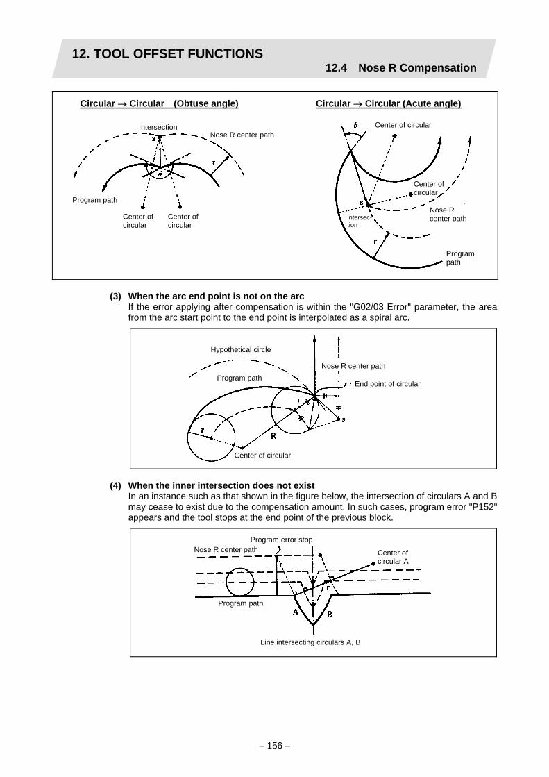
12. TOOL OFFSET FUNCTIONS12.4 Nose R Compensation
– 156 –
Circular → Circular (Obtuse angle) Circular → Circular (Acute angle)
Center of circularIntersection
Nose Rcenter path
Center ofcircular
Nose R center path
Programpath
Program path
Center ofcircular
Intersec-tion
Center ofcircular
(3) When the arc end point is not on the arc If the error applying after compensation is within the "G02/03 Error" parameter, the area
from the arc start point to the end point is interpolated as a spiral arc.
Program path
Center of circular
Hypothetical circle
Nose R center path
End point of circular
(4) When the inner intersection does not exist In an instance such as that shown in the figure below, the intersection of circulars A and B
may cease to exist due to the compensation amount. In such cases, program error "P152" appears and the tool stops at the end point of the previous block.
Program path
Center ofcircular A
Nose R center pathProgram error stop
Line intersecting circulars A, B

12. TOOL OFFSET FUNCTIONS12.4 Nose R Compensation
– 157 –
Tool nose radius compensation cancel
If either of the following conditions is met in the nose R compensation mode, the compensation will be canceled. However, the movement command must be a command which is not a circular command. If the compensation is canceled by a circular command, program error "P151" results.
(1) The G40 command has been executed.
(2) The T00 tool number has been executed.
The cancel mode is established once the compensation cancel command has been read, 5-block pre-reading is suspended and 1-block pre-reading is applies instead.
Tool nose radius compensation cancel operation
(1) Machining an inside corner
Linear → Linear Circular → Linear
End pointEnd point
r = Compensation amountNose R center path
Program path
Nose Rcenter path
Program path
Center of circular

12. TOOL OFFSET FUNCTIONS12.4 Nose R Compensation
– 158 –
(2) Machining an outside corner (obtuse angle) (type A or B can be selected by parameter)
Linear → Linear (Type A) Circular → Linear (Type A)
End pointEnd point
r = Nose radius
Program path
Nose R center path
Program path
Center of circular
Intersection Intersection
Nose R center path
Program path
End pointEnd point Program pathCenter of circular
Nose Rcenter path
Nose Rcenter path
Linear → Linear (Type B) Circular → Linear (Type B)

12. TOOL OFFSET FUNCTIONS12.4 Nose R Compensation
– 159 –
(3) Machining an outside corner (acute angle) (type A or B can be selected by parameter)
Linear → Linear (Type A) Circular → Linear (Type A)
End point
Nose R center path
Program path
Nose Rcenter path
Program path
Center ofcircular
End point
End point
Nose R center path
Program path
Nose Rcenter path
Center of circular
Program path
End point
Linear → Linear (Type B) Circular → Linear (Type B)

12. TOOL OFFSET FUNCTIONS12.4 Nose R Compensation
– 160 –
12.4.3 Other operations during nose R compensation
Changing the compensation direction during nose R compensation
The compensation direction is determined by the nose R compensation commands (G41, G42).
G code Compensation direction G41 Left-side compensation G42 Right-side compensation
The compensation direction can be changed by changing the compensation command in the compensation mode without the compensation having to be first canceled. However, no change is possible in the compensation start block and the following block.
Linear → Linear
r
Nose R center path
Program path
G41
r
G41 G42
r
r
Linear → Circular
Nose R center path
Program path
G41
r
G41 G42G41G42
r
r
r
r
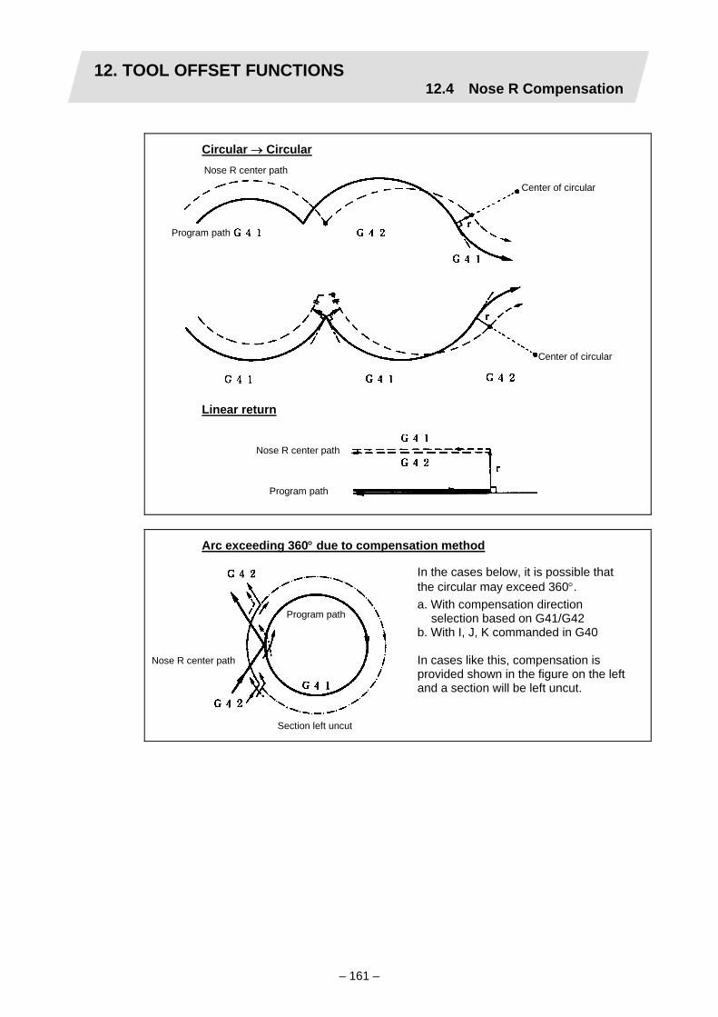
12. TOOL OFFSET FUNCTIONS12.4 Nose R Compensation
– 161 –
Circular → Circular Nose R center path
Program path
Center of circular
Center of circular
Linear return
Nose R center path
Program path
Arc exceeding 360° due to compensation method
Program path
Nose R center path
Section left uncut
In the cases below, it is possible that the circular may exceed 360°. a. With compensation direction
selection based on G41/G42 b. With I, J, K commanded in G40 In cases like this, compensation is provided shown in the figure on the left and a section will be left uncut.

12. TOOL OFFSET FUNCTIONS12.4 Nose R Compensation
– 162 –
Nose R compensation of path closed by G46/G41/G42
(1) G46 command operation (2) G42 → G41 command operation
Program
Intersection
G41 command
Left
Right
(3) G42 → G41 command operation

12. TOOL OFFSET FUNCTIONS12.4 Nose R Compensation
– 163 –
Command for eliminating offset vectors temporarily
When the following command is issued in the compensation mode, the offset vectors are temporarily eliminated and a return is then made automatically to the compensation mode. In this case, the compensation is not canceled, and the tool goes directly from the intersection vector to the point without vectors or, in other words, to the programmed command point. When a return is made to the compensation mode, it goes directly to the intersection.
(1) Reference point return command
Intermediate point
(G41)
N5 G01 U+60. W+60.;
N6 G28 U–80. W+50.; ←
N7 U–120. W+30.;
N8 U+80. W+70.;
(Note 1) The offset vectors do not change with the coordinate system setting (G92)
command.
(2) G33 thread cutting command Nose R compensation does not apply to the G33 block.
Nose R center path
Program path
Intersection
(3) Compound fixed cycles When a compound fixed cycle I command (G70, G71, G72, G73) is assigned, the nose R
compensation is temporarily canceled, the finishing shape to which nose R compensation has been applied is turned with the compensation canceled and, upon completion, a return is automatically made to the compensation mode.
~
~ ~
Temporarily no compensation vectors at intermediate point (Reference point when there is no intermediate point)

12. TOOL OFFSET FUNCTIONS12.4 Nose R Compensation
– 164 –
Blocks without movement
The following blocks are known as blocks without movement.
a. M03;・・・・・・・・・・・・・・・・ M command b. S12; ・・・・・・・・・・・・・・・・ S command c. T0101; ・・・・・・・・・・・・・・ T command d. G04 X500;・・・・・・・・・・・ Dwell e. G10 P01 R50;・・・・・・・・ Compensation amount setting f. G92 X600. Z500.; ・・・・ Coordinate system setting g. Y40. ; ・・・・・・・・・・・・・・・ Movement but not on compensation
plane h. G00; ・・・・・・・・・・・・・・・・ G code only i. U0 ; ・・・・・・・・・・・・・・・・ Movement amount 0 ・・・ Movement amount is 0
(1) When commanded at compensation start
Offset vector cannot be generated for a block without movement.
N1 U60. W30. T0101; N2 G41; N3 G4 X1000; N4 F100; N5 S500; N6 M3; N7 U–100. W20.; N8 U–40. W50.;
(Intersection)
N1 T0101; N2 G41 U120. W30.; N3 G4 X1000; N4 F100; N5 S500; N6 M3; N7 U–100. W20.; N8 U–40. W50.;
(Intersection)
Block withoutmovement
Block withoutmovement
No movement

12. TOOL OFFSET FUNCTIONS12.4 Nose R Compensation
– 165 –
(2) When command is assigned in the compensation mode When 4 or more blocks without movement does not follow in succession in the
compensation mode, the intersection vectors will be created as usual.
N6 U400. W100.; N7 G04 XP1000; ..... N8 X200.;
Block N7 isexecuted here.
When 4 or more blocks without movement follow in succession, the offset vectors are created perpendicularly at the end point of the previous block.
N6 U200. W200.; N7 G4 X1000; N8 F100; N9 S500; N10 M4; N11 X100.; In this case, a cut results.
(3) When commanded together with compensation cancel Only the offset vectors are canceled when a block without movement is commanded
together with the G40 command.
Block without movement
Block without movement
N6 U400. W100.; N7 G40 G04 P1000; N8 U100. W100.;

12. TOOL OFFSET FUNCTIONS12.4 Nose R Compensation
– 166 –
When I, J, K are commanded in G40
(1) When the last movement command block among the 4 blocks before the G40 block is in
the G41or G42 mode, it is considered to be commanded in the vector I, J and K direction from the end point of the last movement command, and compensation is canceled after interpolation up to the intersection with the corresponding hypothetical nose R center path. There is no change in the compensation direction.
Nose R center path
Program path
Hypothetical nose R center path
In this case, care is required since the intersection must be sought even when the command vector is incorrect, as in the figure below, regardless of the compensation direction.
Nose R center path
Program path
Hypothetical nose R center path
When the intersection calculation and offset vectors cannot be sought, perpendicular vectors are created in the block before G40.
Nose R center path
Program path
Hypothetical nose R center path
X
Z
N1 (G41) G1Z__; N2 G40 XaZbIiKk;
When the I, K signs are incorrect in the above program example

12. TOOL OFFSET FUNCTIONS12.4 Nose R Compensation
– 167 –
(2) Care should be taken with the G40 command after an circular command since there is a danger of a section being left uncut when the circular exceeds 360° due to the contents of I, J and K.
Section left uncut
Nose R center path
Program path
Corner movement
When a multiple number of offset vectors are created at the joins between movement command blocks, the tool will move in a linear between those vectors. This action is called corner movement. When the vectors do not coincide, the tool moves in order to machine the corner although this movement is part and parcel of the join block. Consequently, operation in the single block mode will execute the previous block + corner movement as a single block and the remaining joining movement + following block will be executed as a single block in the following operation.
Stop point with single block
Nose R center path
Program path
Center of circular
This movement and feedrate fallunder block N2.
N1 (G42) G01 W200.; N2 G03 I150.; N3 G40 G1 U–300. W150. I100. K–100.;

12. TOOL OFFSET FUNCTIONS12.4 Nose R Compensation
– 168 –
12.4.4 G41/G42 commands and I, J, K designation
Function and purpose
The compensation direction can be intentionally changed by issuing the G41/G42 command and I, J, K in the same block.
Command format
G18 (Z-X plane) G41/G42 X__ Z__ I__ K__ ;
Assign a linear command (G00, G01) in a movement mode.
I, K type vectors (G18 X-Z plane selection)
The new I, K type vector (G18 plane) created by this command is now described. (Similar descriptions apply to vector I, J for the G17 plane and to J, K for the G19 plane.) As shown in the figures below, the vectors with a size equivalent to the compensation amount are made to serve as the I, K type offset vector perpendicularly to the direction designated by I, K without the intersection of the programmed path being calculated. The I, K vector can be commanded even in the mode (G41/G42 mode in the block before) and even at the compensation start (G40 mode in the block before).
(1) When I, K is commanded at compensation start
Program path
Nose R center path
(2) When there are no movement commands at the compensation start
(G40)
N100 G41 U200. W100. K150. T0101; N110 G04 X1000; N120 G01 F1000; N130 S500; N140 M03; N150 Z150.;
~ ~
(G40)
N1 G41 K150. T0101; N2 U200. W100.; N3 W150.;
~ ~

12. TOOL OFFSET FUNCTIONS12.4 Nose R Compensation
– 169 –
(3) When I, K has been commanded in the mode (G18 plane)
Program path
Nose R center pathPath for intersection calculation
(2)
(1)
(4) When I, K has been commanded in a block without movement
N1 G41 T0101 G01 F1000; N2 U200. W100.; N3 G41 K50.; N4 W150.; N5 G40;
(G18 G41 T0010) N100 G41 G01 W150. I50.; N110 G02 W100. K50.; N120 G01 W–150.;
~ ~
(1) I, K type vector (2) Intersection calculation type vector

12. TOOL OFFSET FUNCTIONS12.4 Nose R Compensation
– 170 –
Direction of offset vectors
(1) In G41 mode Direction produced by rotating the direction commanded by I, K through 90° to the left
from the forward direction of the Y axis (3rd axis) as seen from the zero point
(Example 1) With K100. (Example 2) With K–100. Offset vector direction (0, –100) IK direction
(0, 100) IK direction Offset vector direction
(2) In G42 mode Direction produced by rotating the direction commanded by I, K through 90° to the right
from the forward direction of the Y axis (3rd axis) as seen from the zero point
(Example 1) With K100. (Example 2) With K–100. (0, 100) IK direction Offset vector direction
Offset vector direction (0, –100) IK direction
Selection of offset modal
The G41 or G42 modal can be selected at any time.
N3
Z
T1
N2
N6
(I,K)
N5
X
N4 T2
N1 G28 X0 Z0; N2 G41 T0101 F1000; N3 G01 U200. W100.; N4 G42 W100. I–100. K100; N5 X100. Y–100; N6 G40; N7 M02; %
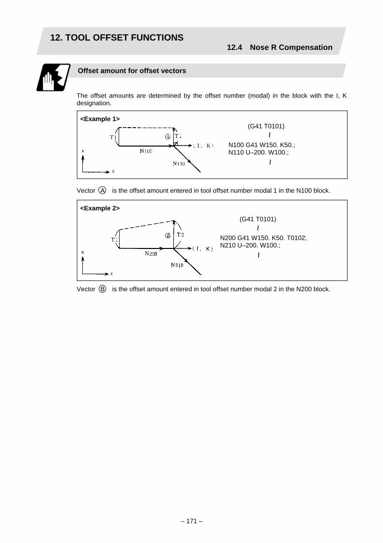
12. TOOL OFFSET FUNCTIONS12.4 Nose R Compensation
– 171 –
Offset amount for offset vectors
The offset amounts are determined by the offset number (modal) in the block with the I, K designation.
<Example 1>
Vector A is the offset amount entered in tool offset number modal 1 in the N100 block.
<Example 2>
Vector B is the offset amount entered in tool offset number modal 2 in the N200 block.
(G41 T0101)
N100 G41 W150. K50.; N110 U–200. W100.;
~ ~
(G41 T0101)
N200 G41 W150. K50. T0102; N210 U–200. W100.;
~ ~

12. TOOL OFFSET FUNCTIONS12.4 Nose R Compensation
– 172 –
Precautions
(1) Issue the I, K type vector in a linear mode (G0, G1). If it is issued in an arc mode at the
start of compensation, program error "P151" will result. An I, K designation in an arc mode functions as an arc center designation in the offset
mode.
(2) When the I, K type vector has been designated, it is not deleted (avoidance of interference) even if there is interference. Consequently, overcutting may arise in such a case.
Cut
N3 N4 N5 N6
(I,K)
X
Z
(3) Refer to the following table for the offset methods based on the presence and/or absence of the G41 and G42 commands and I, K (J) command.
G41/G42 I, K (J) Offset method No No Intersection calculation type vector No Yes Intersection calculation type vector Yes No Intersection calculation type vector Yes Yes I, K type vector
No insertion block
N1 G28 X0 Z0; N2 G41 T0101 F1000; N3 W100.; N4 G41 U–200. W100. K10.;N5 U200. W100.; N6 G40; N7 M02;

12. TOOL OFFSET FUNCTIONS12.4 Nose R Compensation
– 173 –
12.4.5 Interrupts during nose R compensation
MDI interrupt
Nose R compensation is valid in any automatic operation mode - whether memory or MDI operation. An interrupt based on MDI will give the result as in the figure blow after block stop during memory operation.
(1) Interrupt without movement (tool path does not change)
(Stop position with single block)
(2) Interrupt with movement The offset vectors are automatically re-calculated at the movement block after interrupt.
N1 G41 T0101;
N2 U100. W20.;
N3 G3 U–80. W40. R70.; S1000 M3;
MDI interrupt
With linear interrupt N1 G41 T0101;
N2 U100. W20.;
N3 G3 U–80. W40. R70.; U–60. W50.;
U100. W30.;
MDI interrupt

12. TOOL OFFSET FUNCTIONS12.4 Nose R Compensation
– 174 –
Manual interrupt
(1) Interrupt with manual absolute OFF
The tool path is shifted by an amount equivalent to the interrupt amount.
Interrupt
Program path
Tool path aftercompensation
Tool path after interrupt
With circular interrupt N1 G41 T0101;
N2 U100. W20.;
N3 G3 U–80. W40. R70.; G2 U–80. W40. R70.;
G1 W40.;
MDI interrupt

12. TOOL OFFSET FUNCTIONS12.4 Nose R Compensation
– 175 –
(2) Interrupt with manual absolute ON In the incremental value mode, the same operation results as with manual absolute OFF.
Inter-rupt
In the absolute value mode, however, the tool returns to its original path at the end point of the block following the interrupted block, as shown in the figure.
Inter-rupt

12. TOOL OFFSET FUNCTIONS12.4 Nose R Compensation
– 176 –
12.4.6 General precautions for nose R compensation
Assigning the compensation amounts
(1) The compensation amount is normally assigned by designating the number of the
compensation amount by the last 1 digit or 2 digits of the T code. Depending on the machine specifications, the high-order digits may be used. The T code will remain valid once designated until another T code is subsequently commanded.
Besides being used to designate the compensation amounts for nose R compensation, the T codes are also used to designate the compensation amounts for tool length offset.
(2) The compensation amounts are normally changed when a different tool has been selected in the compensation cancel mode. However, when an amount is changed in the compensation mode, the vectors at the end point of the block are calculated using the compensation amount designated in that block.
Errors during nose R compensation
(1) An error results when any of the following commands are programmed during nose R
compensation. G17, 18, 19 ("P112" when a plane differing from that applying during the compensation
has been commanded) G31 ("P608") G74, 75, 76 ("P155") G81 to G89 ("P155")
(2) An error "P158" results when a tool nose point other than 1 to 8 has been designated in the G46 mode.
(3) An error "P156" results when the compensation direction is not determined by the movement vector of the initial cutting command even when the nose R compensation operation has started in the G46 mode and 5 blocks have been pre-read.
(4) An error "P151" results when an circular command is issued in the first or last block of the nose R compensation.
(5) A program error "P157" results when the compensation direction is reversed in the G46 mode.
A parameter can be set to move the tool in the same compensation direction. (Control parameter #8137 G46 no reverse error)
(6) A program error "P152" results during nose R compensation when the intersection is not determined with single block skip in the interference block processing.
(7) A program error results when there is an error in one of the pre-read blocks during nose R compensation.
(8) A program error "P153" results when interference arises under no interference avoidance conditions during nose R compensation.
(9) A program error "P150" results when a nose R compensation command is issued even though the nose R compensation specification has not been provided.

12. TOOL OFFSET FUNCTIONS12.4 Nose R Compensation
– 177 –
12.4.7 Interference check
Function and purpose
A tool, whose tool nose has been compensated under the tool nose R compensation function by the usual 2-block pre-read, may sometimes cut into the workpiece. This is known as interference, and interference check is the function which prevents this from occurring. There are two types of interference check, as indicated below, and each can be selected for use by parameter.
Function Parameter Operation Interference check alarm function
Rad compen intrf byp OFF
A program error results before the execution of the block in which the cut arises, and operation stops.
Interference check avoidance function
Rad compen intrf byp ON
The tool path is changed so that workpiece is not cut into.
Detailed description
(Example)
Avoidance path
Outer diameterof nose R
Cutting with N2Cutting with N2
(1) With alarm function The alarm occurs before N1 is executed and so, using the buffer correction function, N1
can be changed as below and machining can be continued:
N1 G1 X–80. Z20.;
(2) With avoidance function The intersection of N1 and N3 is calculated and the interference avoidance vectors are
created.
(G41) N1 G1 X–200. Z50.; N2 X–200. Z70.; N3 X0. Z120.;

12. TOOL OFFSET FUNCTIONS12.4 Nose R Compensation
– 178 –
Operation during interference avoidance
Solid line vector : valid Broken line vector : invalid
Linear movement
Nose R center path when interference is avoided
Nose R center path without interference check
Program path
Center of circular
Nose R center path when interference is avoided
Program path
Nose R center path without interference check
In the case of the figure below, the groove will be left uncut.
Interference avoidance path
Nose R center path
Program path

12. TOOL OFFSET FUNCTIONS12.4 Nose R Compensation
– 179 –
Interference check alarm
The interference check alarm occurs under the following conditions.
(1) When the interference check alarm function has been selected
(a) When all the vectors at the end block of its own block have been deleted When, as shown in the figure below, vectors 1 to 4 at the end point of the N1 block have all been deleted, program error "P153" results prior to N1 execution.
(2) When the interference check avoidance function has been selected
(a) When there are valid vectors at the end point of the following block even when all the vectors at the end point of its own block have been deleted (i) When, in the figure below, the N2 in interference check is conducted, the N2 end
point vectors are all deleted but the N3 end point vectors are regarded as valid. Program error "P153" now occurs at the N1 end point.
Alarmstop

12. TOOL OFFSET FUNCTIONS12.4 Nose R Compensation
– 180 –
(ii) In a case such as that shown in the figure below, the tool will move in the reverse direction at N2. Program error "P153" now occurs prior to N1 execution.
(b) When avoidance vectors cannot be created
(i) Even when, as in the figure below, the conditions for creating the avoidance vectors are met, it may still be impossible to create these vectors or the interference vectors may interfere with N3. As a result, program error "P153" will occur at the N1 end point when the vector intersecting angle is more than 90°.
Alarm stop
Alarm stop
N4
N2
N1
N3Angle of intersection

12. TOOL OFFSET FUNCTIONS12.4 Nose R Compensation
– 181 –
(ii) Avoidance vectors cannot be created when pre-read prohibit blocks are interfered with and so program error "P153" occurs.
Pre-readprohibit block
(c) When the program advance direction and the advance direction after compensation are reversed.
In the following case, interference is still regarded as occurring even when there is actually no interference.
When grooves which are narrower than the nose R diameter or which have parallel or widening walls are programmed.
Stop
Program path Nose R center path
(G41)
N10 G01 Zz1; N20 Xx1; N30 M02; :
~

12. TOOL OFFSET FUNCTIONS12.5 Programmed Tool Offset Input
– 182 –
12.5 Programmed Tool Offset Input; G10
Function and purpose
The amount of tool offset and workpiece offset can be set or changed by the G10 command. When commanded with absolute values (X, Z, R), the commanded offset amounts serve as the new amounts; when commanded with incremental values (U, W, C), the new offset amounts are equivalent to the commanded amounts plus the current offset amount settings.
Command format
(1) Workpiece offset input (L2)
G10 L2 P__ X__ (U__) Z__ (W__) ;
P_ Offset number X_ X-axis offset amount (absolute) U_ X-axis offset amount (incremental) Z_ Z-axis offset amount (absolute) W_ Z-axis offset amount (incremental)
(2) Tool length offset input (L10)
G10 L10 P__ X__ (U__) Z__ (W__) R__ (C__) Q__ ;
P_ Offset number X_ X-axis offset amount (absolute) U_ X-axis offset amount (incremental) Z_ Z-axis offset amount (absolute) W_ Z-axis offset amount (incremental) R_ Nose R compensation amount (absolute) C_ Nose R compensation amount (incremental) Q_ Hypothetical tool nose point
(3) Tool nose wear offset input (L11)
G10 L11 P__ X__ (U__) Z__ (W__) R__ (C__) Q__ ;
P_ Offset number X_ X-axis offset amount (absolute) U_ X-axis offset amount (incremental) Z_ Z-axis offset amount (absolute) W_ Z-axis offset amount (incremental) R_ Nose R compensation amount (absolute) C_ Nose R compensation amount (incremental) Q_ Hypothetical tool nose point
(4) When there is no L command with tool length offset input (L10) or tool nose wear
offset input (L11) Tool length offset input command : P = 10000 + offset number
(Equivalent to G10 L10 P compensation number) Tool nose wear offset input : P = offset number
(Equivalent to G10 L11 P compensation number)

12. TOOL OFFSET FUNCTIONS12.5 Programmed Tool Offset Input
– 183 –
Detailed description
(1) The following table shows the offset numbers and the setting ranges of the hypothetical
tool nose points.
Setting range Add- ress
Signifi- cance of address L2 L10 L11
P Offset number
0: External workpiece offset
1: G54 workpiece offset
2: G55 workpiece offset
3: G56 workpiece offset
4: G57 workpiece offset
5: G58 workpiece offset
6: G59 workpiece offset
When L command is present:
1 to Max. number of offset sets
When L command is not present:
10001 to 10000 + Max. number of offset sets
When L command is/is not present:
1 to Max. number of offset sets
Q Hypothetical tool nose point
— 0 to 9
(Note 1) The maximum number of offset sets for P (offset number) with tool offset input (L10
or L11) is 20 under the standard specifications and up to a total of 80 with the addition of options.
(2) The setting range for the offset amount is given blow. Program error "P35" occurs for any value not listed in the table after command unit
conversion. With an incremental value command, the setting range for the offset amount is the sum of
the present setting and command value.
Tool length offset amount Tool wear offset amount Input unit Metric system Inch system Metric system Inch system
IS - B ±99999.999 (mm) ±9999.9999 (inch) ±99999.999 (mm) ±9999.9999 (inch)IS - C ±9999.9999 (mm) ±999.99999 (inch) ±9999.9999 (mm) ±999.99999 (inch)
(3) The number of axes that can be commanded is as follows.
• Workpiece offset input : Maximum 5 axes • Tool length offset input : Maximum 3 axes • Tool nose wear offset input : Maximum 3 axes

12. TOOL OFFSET FUNCTIONS12.5 Programmed Tool Offset Input
– 184 –
Precautions and restrictions
(1) Offset setting range check The maximum value of the wear offset amount and the maximum additional value (Setup
parameter 8031/8032) for the wear offset input check respectively take precedence for a single-time offset amount in the maximum value and incremental value command of the wear offset amount, and when an amount greater than these values has been commanded, program error "P35" results.
(2) G10 is an unmodal command and is valid only in the commanded block.
(3) The data changed with workpiece offset input is validated at the next workpiece coordinate system selection command. The data changed with tool length offset input or tool nose wear offset input is validated at the next T command.
(4) Address C is treated as an incremental command value of the tool nose radius in the L10 or L11 command. In L10 and L11, address C is handled as the nose R incremental command value, thus, an absolute value cannot be commanded for the axis named "C".
(5) If an illegal L number or P number is commanded, program error "P172" or "P170" will result, respectably. Program error "P170" occurs when the P command is omitted.
(6) Program error "P35" results when the offset amount exceeds the setting range.
(7) X, Z and U, W are input together in a single block but when an address that commands the same offset input (X, U or Z, W) is commanded, the address which is input last is valid.
(8) Offset will be input if even one address following "G10 L (2/10/11) P__" is commanded. The command is ignored when not even a single command has been assigned. (Offset is not input.)
(Example) G10 L10 P3 Z50.;
↓
(9) When the absolute/incremental address is invalid (when 8106 ABS/INC Addr. is invalid), addition is possible with the incremental amount using the G91 mode + absolute value address command.
(10) Decimal points are valid for offset amounts.
(11) Program error "P171" occurs when this command is input even though the corresponding specifications have not been provided.
(12) G40 to G42 are ignored when they have been commanded in the same block as G10.
(13) Do not command G10 in the same block as fixed cycles and subprogram call commands. This will cause malfunctioning and program errors.
(14) When a T command has been issued in the same block as G10 with Tmove (tool offset operation) as 0 (Base common parameter 1317), the offset will be accomplished in the following block.
[Tool length data] # Z 3 50.000 Input as per left

12. TOOL OFFSET FUNCTIONS12.6 Common System Offset
– 185 –
12.6 Common System Offset
Function and purpose
In the multi-system NC, when the basic common parameter 1334 Tcom∗ is turned ON, offset data is valid for all common offset systems. With this convenient function, one tool can be used in multiple systems. Programming is easy; there is no need to distinguish the T command in the machining program.
Command format
T □□ □□ ;
Tool offset number Tool number T command
T □□ ;
Tool offset number T command
Detailed description
(1) This command is issued with 4 digits or 2 digits that follow the T address. (When two
digits are commanded, the tool number will not be output.) (2) One set of this command can be issued in one block. (3) The T function can be used simultaneously with any other command. However, when in the
same block as the movement command, there are two types of command execution procedures. (Which procedure is suitable depends on the basic common parameter Tmove). (a) Execute the T function after movement is completed. (b) Execute T function and movement command at the same time.
(i) Tmove = 0
Offset amount Tool path after offset
Machining program path
N1 T0101; N2 X100. Z200.;
(ii) Tmove = 1
Offset amount
Tool path after offset
Machining program path
N1 T0101; N2 X100. Z200.;

13. PROGRAM SUPPORT FUNCTIONS13.1 Fixed Cycles for Turning
– 186 –
13. PROGRAM SUPPORT FUNCTIONS
13.1 Fixed Cycles for Turning
Function and purpose
When performing rough cutting and other such operations during turning, these functions enable shapes normally commanded in several blocks to be commanded in a single block. In other words, they simplify the machining program.
G code Function G77 Longitudinal turning cycle G78 Thread cutting cycle G79 Face turning cycle
Command format
G77 X/U_ Z/W_ R_ F_ ;
(Same for G78, G79)
Detailed description
(1) Fixed cycle commands are modal G codes and so they are valid until another command
in the same modal group or a cancel command is issued. The following G code cancel commands are available.
G00, G01, G02, G03 G07, G09, G10, G11, G27, G28, G29, G30, G31, G33, G34, G37, G92, G52, G53, G65,
(2) There are two fixed cycle call types, movement command block call and block-by-block call. These are selected by a control parameter setting.
A movement command block call serves to call the fixed cycle macro subprogram only when there is an axial movement command in the fixed cycle mode. The block-by-block call serves to call the fixed cycle macro subprogram in each block in the fixed cycle mode. Both types are executed until the fixed cycle is canceled.
(3) A manual interrupt can be applied while a turning fixed cycle (G77 to G79) is being executed. Upon completion of the interrupt, however, the tool must be returned to the position where the manual interrupt was applied and then the turning fixed cycle should be resumed. If it is resumed without the tool having been returned, all subsequent operations will deviate by an amount equivalent to the manual interrupt.

13. PROGRAM SUPPORT FUNCTIONS13.1 Fixed Cycles for Turning
– 187 –
13.1.1 Longitudinal cutting cycle; G77
Straight cutting
This function enables continuous straight cutting in the longitudinal direction using the following command.
G77 X/U_ Z/W_ F_;
X axis
Z axis
Taper cutting
This function enables continuous taper cutting in the longitudinal direction using the following command.
G77 X/U_ Z/W_ R_ F_;
X axis
Z axis
R : Taper depth (radius designation, incremental value, sign required)
With a single block, the tool stops at the end points of operations 1, 2, 3 and 4.
(R) : Rapid traverse (F) : Cutting feed
(R) : Rapid traverse (F) : Cutting feed

13. PROGRAM SUPPORT FUNCTIONS13.1 Fixed Cycles for Turning
– 188 –
Depending on the U, W and R signs, the following shapes are created.
(1) U < 0, W < 0, R < 0 (2) U < 0, W < 0, R > 0
(3) U > 0, W < 0, R < 0 (4) U > 0, W < 0, R > 0
Program error "P191 Taper length error" results with shapes (2) and (3) unless the following condition is satisfied.
| U/2 | ≥ | r |

13. PROGRAM SUPPORT FUNCTIONS13.1 Fixed Cycles for Turning
– 189 –
13.1.2 Thread cutting cycle; G78
Straight cutting
This function enables straight thread cutting using the following command.
G78 X/U_ Z/W_ F/E_;
X axis
Z axis
(R) : Rapid traverse(F) : Cutting feed
Taper cutting
This function enables taper thread cutting using the following command.
G78 X/U_ Z/W_ R_ F/E_;
X axis
Z axis
(R) : Rapid traverse(F) : Cutting feed
R: Taper depth (radius designation, incremental value, sign required)

13. PROGRAM SUPPORT FUNCTIONS13.1 Fixed Cycles for Turning
– 190 –
Details for chamfering
α : Chamfering amount of thread If the thread lead is assumed to be
L, then the parameter can be set in 0.1L units from 0 to 12.7L.
θ : Chamfering angle of thread The parameter can be set in 1° units
from 0 to 89°
With a single block, the tool stops at the end points of operations 1, 3 and 4. When the feed hold function is applied during a thread cutting cycle, automatic operation will stop if no thread is then being cut. If thread cutting is proceeding, operation stops at the next movement completion position (completion of operation 3) of the thread cutting. The dry run valid/invalid status does not change during thread cutting.

13. PROGRAM SUPPORT FUNCTIONS13.1 Fixed Cycles for Turning
– 191 –
Depending on the U, W and R signs, the following shapes are created.
(1) U < 0, W < 0, R < 0 (2) U < 0, W < 0, R > 0
(3) U > 0, W < 0, R < 0 (4) U > 0, W < 0, R > 0
Program error "P191 Taper length error" results with shape (2) and (3) unless the following condition is satisfied.
| U/2 | ≥ | r |

13. PROGRAM SUPPORT FUNCTIONS13.1 Fixed Cycles for Turning
– 192 –
13.1.3 Face cutting cycle; G79
Straight cutting
This function enables continuous straight cutting in the face direction using the following command.
G79 X/U_ Z/W_ F_;
X axis
Z axis
XZ W
(R): Rapid traverse(F): Cutting feed
3(F)
2(F) 4(R)
1(R)
U2

13. PROGRAM SUPPORT FUNCTIONS13.1 Fixed Cycles for Turning
– 193 –
Taper cutting
This function enables continuous taper thread cutting using the following command.
G78 X/U_ Z/W_ R_ F_;
X axis
Z axis
X Z W
(R): Rapid traverse(F): Cutting feed
3(F)
2(F) 4(R)
1(R)
R: Taper depth (radius designation, incremental value, sign required)
r
U 2
With a single block, the tool stops at the end points of operations 1, 2, 3 and 4.

13. PROGRAM SUPPORT FUNCTIONS13.1 Fixed Cycles for Turning
– 194 –
Depending on the U, W and R signs, the following shapes are created.
(1) U < 0, W < 0, R < 0 (2) U < 0, W < 0, R > 0
(3) U > 0, W < 0, R < 0 (4) U > 0, W < 0, R > 0
Program error "P191 Taper length error" results with shapes (2) and (3) unless the following condition is satisfied.
| w | ≥ | r |

13. PROGRAM SUPPORT FUNCTIONS13.2 Compound Fixed Cycles
– 195 –
13.2 Compound Fixed Cycles
Function and purpose
These functions enable prepared fixed cycle to be executed by commanding the corresponding program in a block. The types of fixed cycles are listed below.
G code Function G70 Finishing cycle G71 Longitudinal rough cutting cycle (finished shape chamfering) G72 Face rough cutting cycle (finished shape chamfering) G73 Formed material rough cutting cycle
Compound fixed cycles I
G74 Face cut-off cycle G75 Longitudinal cut-off cycle G76 Compound thread cutting cycle
Compound fixed cycles II
(1) If, with any of the above functions for the compound canned cycle I (G70 to G73), the finished shape program has not been entered in the memory, the function cannot be used.
Command format
G70 A_ P_ Q_ ; G71 U_ R_ ; G71 A_ P_ Q_ U_ W_ F_ S_ T_ ; G72 W_ R_ ; G72 A_ P_ Q_ U_ W_ F_ S_ T_ ; G73 U_ W_ R_ ; G73 A_ P_ Q_ U_ W_ F_ S_ T_ ; G74 R_ ; G74 X(U)_ Z(W)_ P_ Q_ R_ F_ ; (Same for G75) G76 P_ R_ ; G76 X(U)_ Z(W)_ P_ Q_ R_ F_ ;
Refer to the explanation of each G code (13.2.1 and following) for details on each address.
Detailed description
(1) The A, P and Q commands of the compound fixed cycles I are described below.
(a) When the A command is not present, P and Q in the program now being executed are called.
When the A command is present and the P command is not present, the head block of the program designated by the A command is treated as the P command.
(b) When the Q command is not present, operation continues until the M99 command is located. When both the Q and M99 commands are not present, operation continues until the final block in the finished shape program.
(2) Two pre-read blocks are required to create a finished shape program.

13. PROGRAM SUPPORT FUNCTIONS13.2 Compound Fixed Cycles
– 196 –
13.2.1 Longitudinal rough cutting cycle I; G71
Function and purpose
This function calls the finished shape program and, while automatically calculating the tool path, performs rough cutting in the longitudinal direction.
Command format
G71 Ud Re ; G71 Aa Pp Qq Uu Ww Ff Ss Tt ;
Ud Cut amount "d" (cut amount without P, Q commands) (modal) ・・・・・・・・・ Variable parameter valid Re Retract amount "e" (modal) ・・・・・・・ Variable parameter valid Aa Finished shape program number (program being executed when omitted) Pp Finished shape start sequence number (program head when omitted) Qq Finished shape end sequence number (up to end of program when omitted) Up to M99 command when M99 comes first even if Q command is present Uu X-axis direction finishing allowance (diameter or radius designation) Ww Z-axis direction finishing allowance Ff Cutting feedrate Ss Spindle speed Tt Tool command
Detail of retract operation
(Cycle command point)
Cut amount
Finishing allowance
(Note 1) A "variable parameter" is a parameter which can use a parameter setting value without the issue of a program command or a parameter which is that parameter value rewritten by the program command.
(Note 2) The U command applied to the finishing allowance when it is in the same block as the A, P and Q commands.

13. PROGRAM SUPPORT FUNCTIONS13.2 Compound Fixed Cycles
– 197 –
Cutting shape
It must be ensured that the finished shape changes monotonically (increase or decrease only) in both the X- and Z-axis directions. Program error "P203 D cmnd figure error (MRC)" occurs with the following shapes.
(1) When there is movement away from the Z axis
(2) When there is no Z axis movement in the second block
Oppositemovement
No Z-axis movement
(3) When the depth of the finished shape X axis is smaller than cut amount "d"
(Note) For the following shape, no program error occurs but the program performs rough cutting down to the X coordinate of the first block and traces the specified shape for finishing.
X coordinate of the first block

13. PROGRAM SUPPORT FUNCTIONS13.2 Compound Fixed Cycles
– 198 –
Configuration of a cycle
A cycle is composed as shown below.
(R) : Rapid traverse(F) : Cutting feed
Based on shapeprogram command
Cut amount
The cut amount is designated by "d". However, it is possible to change the cut amount with each cutting pass by setting the cut change amount (∆d) using a parameter. Program error "P204 E cmnd fixed cycle error (MRC)" results when "d" is less than "∆d".
Remainder
1st cutting pass d + ∆d
2nd cutting pass d
3rd cutting pass d – ∆d 4th cutting pass d + ∆d d, d – ∆d, d + ∆d are repeated Final cutting pass Remainder
~

13. PROGRAM SUPPORT FUNCTIONS13.2 Compound Fixed Cycles
– 199 –
Nose R compensation
When this cycle is commanded with the nose R compensation mode still in force, nose R compensation is applied to the finished shape program covered by this cycle and the cycle is executed for this shape. However, when this cycle is commanded with the nose R compensation mode still in force, the compensation is applied to the shape as follows.
• The mode is temporarily canceled immediately before the cycle. • It starts up with the finished shape program. • The end block of this program serves as the pre-read prohibit block.
Shape with nose Rcompensation applied G71 A__ U__ W__ ・・・ ;
Command point
Finished shape program
Temporary cancellation

13. PROGRAM SUPPORT FUNCTIONS13.2 Compound Fixed Cycles
– 200 –
Others
(1) After the cutting, the remainder is made the cut amount. However, if this amount is less
than the value set by parameter, finishing rough cutting is executed and the workpiece is not cut.
(2) Finishing allowance direction The finishing allowance direction is determined by the shape as follows. A→B→C apply
for the finishing program.

13. PROGRAM SUPPORT FUNCTIONS13.2 Compound Fixed Cycles
– 201 –
13.2.2 Face rough cutting cycle I; G72
Function and purpose
This function calls the finished shape program and, while automatically calculating the path, performs rough cutting in the face direction.
Command format
G72 Wd Re ; G72 Aa Pp Qq Uu Ww Ff Ss Tt ;
Wd Cut amount "d" (cut amount without P, Q commands) (modal) ・・・・・・・・・ Variable parameter valid Re Retract amount "e" (modal) ・・・・・・・ Variable parameter valid Aa Finished shape program number (program being executed when omitted) Pp Finished shape start sequence number (program head when omitted) Qq Finished shape end sequence number (up to end of program when omitted) Up to M99 command when M99 comes first even if Q command is present Uu X-axis direction finishing allowance (diameter or radius designation) Ww Z-axis direction finishing allowance Ff Cutting feedrate Ss Spindle speed Tt Tool command
Cut amount
Detail of retractoperation
Cycle command point
Finishing allowance

13. PROGRAM SUPPORT FUNCTIONS13.2 Compound Fixed Cycles
– 202 –
The F, S and T commands in the finished shape program are ignored and the value in the rough cutting cycle command or previous value is valid.
(Note 1) A "variable parameter" is a parameter which can use a parameter setting value without the issue of a program command or a parameter which is that parameter value rewritten by the program command.
(Note 2) The W command applies to the finishing allowance when it is in the same block as the A, P and Q commands.
Cutting shape
It must be ensured that the finished shape changes monotonically (increase or decrease only) in both the X- and Z-axis directions. Program error "P203 D cmnd figure error (MRC)" occurs with the following shapes.
(1) When there is movement away from the X axis
(2) When there is no X axis movement in the second block
Oppositemovement ofX axis
No X-axismovement
(3) When the depth of the finished shape X axis is smaller than cut amount "d"

13. PROGRAM SUPPORT FUNCTIONS13.2 Compound Fixed Cycles
– 203 –
(Note) For the following shape, no program error occurs but the program performs rough cutting down to the Z coordinate of the 1st block and traces the specified shape for finishing.
Z coordinate of the 1st block
Configuration of a cycle
A cycle is composed as below.
Based on shape program command
R : Rapid traverseF : Cutting feed

13. PROGRAM SUPPORT FUNCTIONS13.2 Compound Fixed Cycles
– 204 –
Cut amount
The cut amount is designated by "d". However, it is possible to change the cut amount with each cutting pass by setting the cut change amount (∆d) using a parameter. When d < ∆d, a program error "P204 E cmnd fixed cycle error (MRC)" will occur.
Remainder
1st cutting pass d + ∆d
2nd cutting pass d
3rd cutting pass d – ∆d
4th cutting pass d + ∆d
d, d – ∆d, d + ∆d are repeated
Final cutting pass Remainder
~
Nose R compensation
When this cycle is commanded with the nose R compensation mode still in force, nose R compensation is applied to the finished shape program covered by this cycle and the cycle is executed for this shape. However, when this cycle is commanded with the nose R compensation mode still in force, the compensation is applied to the shape as follows.
• The mode is temporarily canceled immediately before the cycle. • It starts up with the finished shape program. • The end block of this program serves as the pre-read prohibit block.
Shape with nose Rcompensation applied
Finished shape
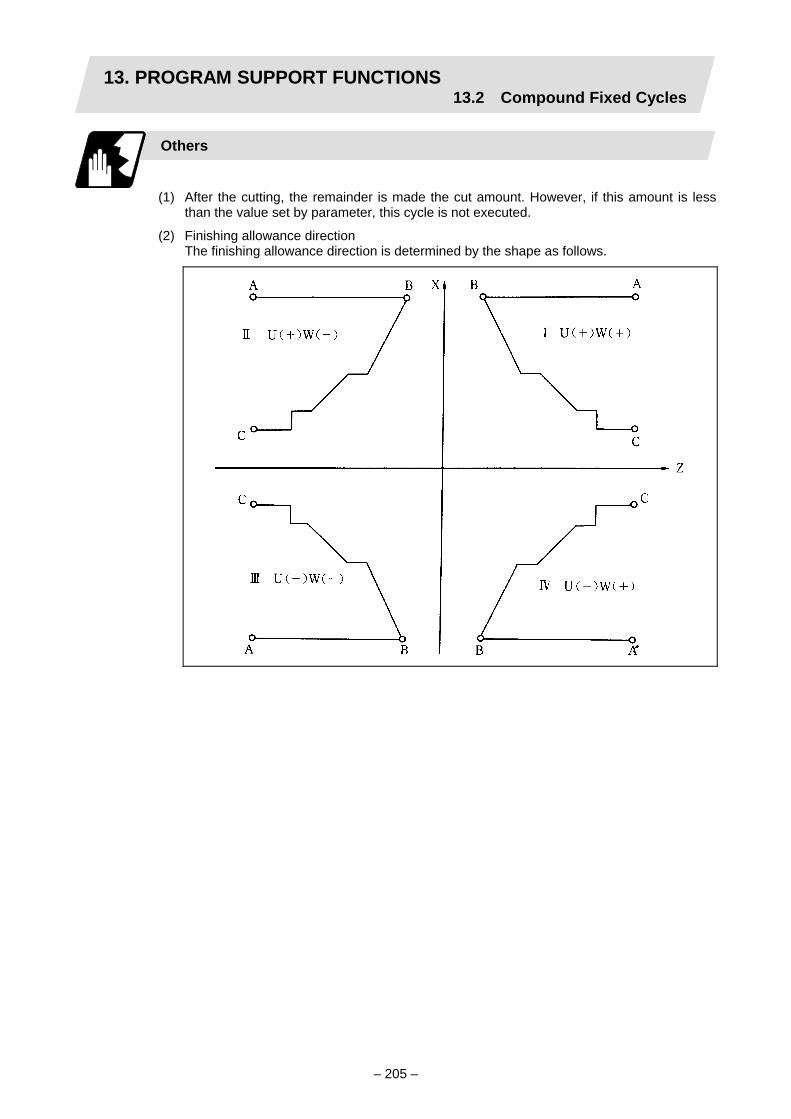
13. PROGRAM SUPPORT FUNCTIONS13.2 Compound Fixed Cycles
– 205 –
Others
(1) After the cutting, the remainder is made the cut amount. However, if this amount is less
than the value set by parameter, this cycle is not executed.
(2) Finishing allowance direction The finishing allowance direction is determined by the shape as follows.

13. PROGRAM SUPPORT FUNCTIONS13.2 Compound Fixed Cycles
– 206 –
13.2.3 Formed material rough cutting cycle; G73
Function and purpose
This calls the finished shape program, automatically calculates the path and performs rough machining while cutting the workpiece into the finished shape.
Command format
G73 Ui Wk Rd ; G73 Aa Pp Qq Uu Ww Ff Ss Tt ;
Ui X-axis direction cutting allowance i Wk Z-axis direction cutting allowance k Rd Number of divisions d Aa Finished shape program number (program being executed when omitted) Pp Finished shape start sequence number (program head when omitted) Qq Finished shape end sequence number (up to end of program or M99 when omitted) Uu X-axis direction finishing allowance u Ww Z-axis direction finishing allowance w
Ff Cutting feedrate (F function) Ss Spindle speed (S function) Tt Tool selection (T function)
• Cutting allowances when P, Q commands are not present.
• Modal data; variable parameters are valid.• Sign is ignored. • Radius designation applies to the cutting
allowance.
• Cutting allowance when P, Q commands are present.
• Sign is ignored. • Diameter/radius designation changes in
accordance with the parameters. • The shift direction is determined by the
shape. For details, reference should be made to the "finishing allowance direction" for G71.
The F, S and T commands in the finished shape program are ignored and the value in the rough cutting cycle command or previous value is valid.

13. PROGRAM SUPPORT FUNCTIONS13.2 Compound Fixed Cycles
– 207 –
(Note 1) A "variable parameter" is a parameter which can use a parameter setting value without the issue of a program command or a parameter which is that parameter value rewritten by the program command.
(Note 2) With a single block, operation stops at the end point of each block. (Note 3) When the finished shape is specified in a separate program or ends with M99,
operation proceeds to the block next to G73 after execution of G73. When the finished shape is specified with P or Q in the same program, operation
proceeds to the block next to the one specified by Q after execution of G73.
Finished shape
In the program, S → A → E in the previous program are commanded. The section between A and E must be a shape with monotonous changes in both the X-axis and Z-axis directions.
1 cycle configuration
A cycle is configured as shown below.
1 : Based on shape program with shape profiling
2 : Rapid traverse on return

13. PROGRAM SUPPORT FUNCTIONS13.2 Compound Fixed Cycles
– 208 –
Cut amount
The cut amount is the value produced by dividing the cutting allowances (i, k) by the number of divisions (d–1). X-axis direction i/(d–1) Z-axis direction k/(d–1) When divisions cannot be made, chamfering is performed and adjustment is made at the final pass.
Remainder
Remainder
Nose R compensation
When this cycle is commanded with the nose R compensation mode still in force, nose R compensation is applied to the finished shape program covered by this cycle and the cycle is executed for this shape. However, when this cycle is commanded with the nose R compensation mode still in force, the compensation is temporarily canceled immediately before this cycle and started at the head block of the finished shape program.

13. PROGRAM SUPPORT FUNCTIONS13.2 Compound Fixed Cycles
– 209 –
Example of program
G28 XZ; G0 X80. Z50.; G73 U10. W10. R3; G73 P10. Q20. U2. W2. F100.; N10 G1 X20. Z50. F150.; G1 X20. Z30.; G1 X40. Z20.; G1 X40. Z10.; N20 G1 X50. Z5.; M02;
Shift direction
Cutting direction
Operation
Others
(1) Cutting direction
The cutting direction is determined according to the following table by the finished program shape.
1 2 3 4 X axis A < E A < E A >= E A >= E
General Z axis – + + –
Drawing S
S1
E
A
S
S1
E
A
S
S1
E
A
SS1
E
A
X axis – – + + Z axis – + + –

13. PROGRAM SUPPORT FUNCTIONS13.2 Compound Fixed Cycles
– 210 –
13.2.4 Finishing cycle; G70
Function and purpose
After rough cutting have been carried out by the G71 to G73 commands, finishing cutting can be performed by the following command.
Command format
G70 A_ P_ Q_ ;
A Finished shape program number (program being executed when omitted) P Finished shape start sequence number (program head when omitted) Q Finished shape end sequence number (up to end of program when omitted)
(1) The F, S and T commands in the finished shape program are valid during the finishing cycle.
(2) When the G70 cycle is completed, the tool returns to the start point by rapid traverse and the next block is read.
(Example 1) When a sequence number is designated
N100 G70 P200 Q300; N200 ・・・・・・ ; N110 N300 ・・・・・・ ; N120 N200 N300 N310
(Example 2) When a program number is designated
N100 G70 A100; N110 ・・・・・・ ; G01 X100 Z50 F0.5; N120 ・・・・・・ ;
M99;
If the N100 cycle is executed in either Example 1 or Example 2, the N110 block is executed next.
O100
~ ~
~
~ ~
~ ~
~
Finished shape program

13. PROGRAM SUPPORT FUNCTIONS13.2 Compound Fixed Cycles
– 211 –
13.2.5 Face cut-off cycle; G74
Function and purpose
The G74 fixed cycle automatically enters a groove in the face direction of the workpiece by commanding the coordinates of the groove end point, cut amount, cutter shift amount and cutter escape at the bottom of the cut.
Command format
G74 Re ; C74 X/(U)x Z/(W)z Pi Qk Rd Ff ;
Re Return amount (no X/U, P commands) (modal).....Variable parameter valid X/Ux B point X coordinate (absolute/incremental value) Z/Wz B point Z coordinate (absolute/incremental value) Pi Tool shift amount (radius designation, incremental value, sign not required) Qk Cut amount (radius designation, incremental value, sign not required) Rd Escape at the bottom of the cut Ff Feedrate
(Start point)
(8) (7)(10)
(11)
(9)
(6)
(5)(4) (3) (2)
(12)(1)
• Operation (9) as well as operation (12) immediately before the final cycle are executed with the remainder amount.
• Operations (2), (4), (6), (8), (10), (11) and (12) are executed at the rapid traverse rate.

13. PROGRAM SUPPORT FUNCTIONS13.2 Compound Fixed Cycles
– 212 –
Single block stop
Operation stops at each block from (1) to (12).
Others
(1) "e" can also be set by parameter. (It is rewritten by the program command.)
(2) When X/U and P are omitted or when the values of "x" and "i" are "0", operation will apply to the Z axis only.
(3) A case where the X/U or Z/W command is not present is treated as the assignment of a parameter setting command (G74 Re). If Re as well as the X/U or Z/W command is not present, no processing results.
(4) When the value of cut amount "k" is higher than hole depth "w", the command is executed with "k" equal to "w".
(5) A program error "P204 E cmnd fixed cycle error (MRC)" results in the following cases.
(a) When "i" is 0 or P has not been commanded even though X/U has been commanded
(b) When tool shift amount "i" is greater than the "x" movement amount
(c) When the escape amount "d" is greater than the shift amount "i"
(d) When the return amount "e" is greater than the cut amount "k"

13. PROGRAM SUPPORT FUNCTIONS13.2 Compound Fixed Cycles
– 213 –
13.2.6 Longitudinal cut-off cycle; G75
Function and purpose
The G75 fixed cycle automatically enters a groove in the longitudinal direction of the workpiece by commanding the coordinates of the groove end point, cut amount, cutter shift amount and cutter escape at the bottom of the cut.
Command format
G75 Re ; C75 X/(U)x Z/(W)z Pi Qk Rd Ff ;
Re Return amount (no X/U, P commands) (modal).....Variable parameter valid X/Ux B point X coordinate (absolute/incremental value) Z/Wz B point Z coordinate (absolute/incremental value) Pi Cut amount (radius designation, incremental value, sign not required) Qk Tool shift amount (radius designation, incremental value, sign not required) Rd Escape at the bottom of the cut Ff Feedrate
(Start point)
(5)
(3)(2)
(10)
(9)(8)
(7)(6)
(11)
(4)
(1)(12)
• Operation (9) as well as operation (12) immediately before the final cycle are executed with the remainder amount.
• Operations (2), (4), (6), (8), (10), (11) and (12) are executed at the rapid traverse rate.

13. PROGRAM SUPPORT FUNCTIONS13.2 Compound Fixed Cycles
– 214 –
Single block stop
Operation stops at each block from (1) to (12).
Others
(1) "e" can also be set by parameter. (It is rewritten by the program command.)
(2) When Z/W and Q are omitted or when the values of "z" and "k" are "0", operation will apply to the X axis only.
(3) A case where both the X/U and Z/W commands are not present is treated as the assignment of a parameter setting command (G74 Re). If Re as well as the X/U and Z/W commands is not present, no processing results.
(4) When the value of cut amount "i" is higher than hole depth "u/2", the command is executed with "i" equal to "u/2".
(5) A program error "P204 E cmnd fixed cycle error (MRC)" results in the following cases.
(a) When "k" is 0 or Q has not been commanded even though Z/W has been commanded
(b) When tool shift amount "k" is greater than the "z" movement amount
(c) When the escape amount "d" is greater than the shift amount "k"
(d) When the return amount "e" is greater than the cut amount "i"

13. PROGRAM SUPPORT FUNCTIONS13.2 Compound Fixed Cycles
– 215 –
13.2.7 Compound thread cutting cycle; G76
Function and purpose
The G76 fixed cycle enables the workpiece to be cut at the desired angle by designating the thread cutting start point and end point, and it automatically cuts so that the cutting cross section (cutting torque) per cutting pass is constant. Various longitudinal direction threads can be cut by bearing in mind the command value for the thread end point coordinate and taper height component.
Command format
G76 Pmra Q∆d min Rd ; G76 X/(U) Z/(W) Ri Pk Q∆d Ff ;
m Number of cutting passes for finishing: 00 to 99 (modal) r Chamfering amount: 00 to 99 (modal)
The chamfering width based on thread lead "λ" is designated by a 2-digit integer without decimal point from 0.0 λ to 9.9 λ.
a Tool nose angle (thread angle): 00 to 99 (modal) The angle from 0° to 99° is assigned in 1° units. "m", "r" and "a" are commanded in succession in address P. (Example) When "m" = 5, "r" = 1.5 and "a" = 0°, P is 051500 and the
leading and trailing "0" cannot be omitted. ∆d min Minimum cut amount (modal)
This is the clamping value for guaranteeing the cut amount of a single cutting pass and it is valid only for rough cutting. Finishing is performed by the cutting allowance designated separately. When the calculated value for the cut amount of a single cutting pass is less than ∆d min, the clamping is performed at ∆d min.
d Finishing allowance (modal) X/U The X coordinate of the end point for the thread is commanded by an
absolute or incremental value. Z/W The Z coordinate of the end point for the thread is commanded by an
absolute or incremental value. i Taper height component (radius value) for thread
Straight thread when "i" is 0. k Thread height is commanded by a positive radial value. ∆d The cut amount of the first cutting pass is commanded by a positive radius
value. λ Thread lead
(Note 1) The two above G76 commands cannot be placed in the same block. The data commanded by P, Q and R are automatically identified according to the
presence or absence of the X/U and Z/W axis addresses. Command the axis address before P, Q or R.
(Note 2) Parameter settings can be used for the above "m", "r", "a", "∆d min" and "d" modal data but these parameter settings are rewritten by the program commands.
(Note 3) The chamfering amount designation is valid even for thread cutting fixed cycles.

13. PROGRAM SUPPORT FUNCTIONS13.2 Compound Fixed Cycles
– 216 –
(Note 4) Program error "P204 E cmnd fixed cycle error (MRC)" results in the following cases.
(a) When "a" is outside the rating.
(b) When both the X and Z commands have not been issued or when the start and end point coordinates are the same for either the X or Z command.
(c) When the thread is greater than the movement of the X axis at the thread bottom.
(Note 5) The precautions for the thread cutting command (G33) and thread cutting cycle (G78) should be observed.
1 cycle configuration
The tool moves at rapid traverse for operations (1), (2), (5) and (6) in the cycle and at the cutting feed based on the F designation for operations (3) and (4).
When Ri is negative
(6)
(5)
(4)
(3)
(2)
(1)
When Ri is positive
(6)
(5)
(4)(3)
(2)
(1)

13. PROGRAM SUPPORT FUNCTIONS13.2 Compound Fixed Cycles
– 217 –
k
a° ∆d for 1st cutting pass
2nd cutting pass
∆d × √ 2
nth cutting pass ∆d × √ n Finishing allowance "d"
(cutting results for "m" number of passes)
Example of program
X axis
Z axis
The tool moves with rapidtraverse over the solid linesection, and at the cuttingfeed that is F-designatedover the thread cuttingsections.
G76 P021560 Q0.1 R0.2; G76 U–40.0 W–46.0 R9.0 P6.0 Q3.5 F4.0;

13. PROGRAM SUPPORT FUNCTIONS13.2 Compound Fixed Cycles
– 218 –
Interrupt operation
(1) When the feed hold button is pressed while G76 is being executed, automatic operation
will stop upon completion of a block without thread cutting if thread cutting is ongoing. (The feed hold lamp lights immediately in the feed hold mode and it goes off when automatic operation stops.) If thread cutting is not ongoing, the feed hold lamp lights and the feed hold status is established.
(2) The tool stops upon completion of operations (1), (4) and (5) when the mode is switched to another automatic operation mode during the G76 command execution, when automatic operation is changed to manual operations or when single block operation is conducted.
(3) The dry run valid/invalid status during G76 execution does not change during thread cutting.

13. PROGRAM SUPPORT FUNCTIONS13.2 Compound Fixed Cycles
– 219 –
13.2.8 Precautions for compound fixed cycles (G70 to G76)
Precautions
(1) Except for the parameters which have been preset on the setting display unit, command
all the required parameters in the blocks containing the compound fixed cycle commands.
(2) Provided that the finished shape program has been entered in the memory, compound fixed cycle I commands can be executed in the memory or MDI operation mode.
(3) When executing a G70 to G73 command, ensure that the sequence number of the finished shape program specified with P and Q is not duplicated in that program.
(4) The finished shape program specified by P and Q in the G71 to G73 blocks should be prepared so that the maximum number of blocks is 50 for all the commands for corner chamfering, corner rounding and other commands including the automatic insertion blocks based on nose R compensation. If this number is exceeded, program error "P202 Block over (MRC)" results.
(5) The finished shape program specified by the G71 to G73 blocks should be a program with monotonous changes (increase or decrease only) for both the X and Z axes.
(6) Blocks without movement in the finished shape program are ignored.
(7) N, F, S, and T commands in the finished shape program are ignored.
(8) When any of the following commands are present in a finished shape program, program error "P201 Program error (MRC)" results.
• Commands related to reference point return (G27, G28, G29, G30) • Thread cutting (G33) • Fixed cycles • Skip functions (G31)
(9) If subprogram call or macro call commands are present in the finished shape program, these commands will also be executed. Note that if the subprogram is called from the last block in the finish shape program, it will not be executed.
(10) Except for thread cutting cycles, operation stops at the end (start) point of each block in the single block mode.

13. PROGRAM SUPPORT FUNCTIONS13.2 Compound Fixed Cycles
– 220 –
~ ~
~ ~
(11) Remember that, depending on whether the sequence or program number is designated, the next block upon completion of the G71, G72 or G73 command will differ.
(a) When the sequence number is designated
(b) When the program number is designated
The next block is the next block designated by Q. N100 G71 P200 Q500 U__ W__ ・・・ ; N200; N300; N400; N500; N600; Operation moves to the N600 block upon completion of the cycle.
The next block is the next block of the cycle command. N100 G71 A100 U__ W__ ・・・ ; N200 N300 N400 Operation moves to the N200 block upon completion of the cycle.
(12) The next block applying upon completion of the G70 command is the next block of the
command block.
N100・・・・・・ ; N200; N300; N400; N500; N1000 G70 P200 Q500; (or G70 A100 ;) N1100 ・・・・・・ ;
Operation moves to the N1100 block upon completion of the G70 command.
(13) It is possible to apply a manual interrupt while a compound fixed cycle command (G70 to
G76) is being executed. However, upon completion of the interrupt, the tool must first be returned to the position where the interrupt was applied and then the compound fixed cycle must be restarted.
If it is restarted without the tool having been returned, all subsequent movements will deviate by an amount equivalent to the manual interrupt amount.
(14) Compound fixed cycle commands are unmodal commands and so they must be issued every time they are required.
(15) Program error "P203 D cmnd figure error (MRC)" results with the G71 and G72 commands even when, because of nose R compensation, there is no further movement of the Z axis in the second block or the Z axis has moved in the opposite direction.
(16) The common variables set in the G70 to G73 finished shape programs are ignored, and the values set before issuance of the rough cutting cycle command become valid.
(17) If an circular command is present in the first movement block in the finished shape program, program error "P201 Program error (MRC)" results.
~
~
O100 N10 X100. Z50. ; N20
↓
Finished shape program

13. PROGRAM SUPPORT FUNCTIONS13.3 Hole Drilling Fixed Cycles
– 221 –
13.3 Hole Drilling Fixed Cycles; G80 to G89
Function and purpose
These fixed cycles are used for predetermined sequences of machining operations such as normal positioning, hole drilling, boring and tapping, etc., which are specified in a block. The various sequences available using these functions are listed in the table below.
G
code Hole
drilling axis Hole drilling
start Operation at hole bottom
Return operation Application
G80 – – – – Cancel
G83 Z Cutting feed, intermittent feed Dwell Rapid traverse Deep hole drilling
cycle
G84 Z Cutting feed Dwell, spindle reverse rotation Cutting feed Tapping cycle
G85 Z Cutting feed Dwell Cutting feed Boring cycle
G87 X Cutting feed, intermittent feed Dwell Rapid traverse Deep hole drilling
cycle
G88 X Cutting feed Dwell, spindle reverse rotation Cutting feed Tapping cycle
G89 X Cutting feed Dwell Cutting feed Boring cycle
A fixed cycle mode is canceled when the G80 or any G command in the 01 group is issued. The various data will also be cleared simultaneously to zero.
Command format
(1) Face hole drilling
G8∆ X/U__ C/H__ Z/W__ R__ Q__ P__ F__ D__ M__ S (during synchronous tap) ,R__ K__ ;
G8∆ Hole machining mode (G83, G84, G85) X/U__ C/H__ Hole positioning data Z/W__ R__ Q__ P__ F__ D__ M__ S (during synchronous tap) ,R__ Hole machining data K__ Number of repetitions
(2) Longitudinal hole machining
G8□ Z/W__ C/H__ X/U__ R__ Q__ P__ F__ D__ M__ S (during synchronous tap) ,R__ K__ ;
G8□ Hole machining mode (G87, G88, G89) Z/W__ C/H__ Hole positioning data X/U__ R__ Q__ P__ F__ D__ M__ S (during synchronous tap) ,R__ Hole machining data K__ Number of repetitions
(3) Cancel
G80 ;

13. PROGRAM SUPPORT FUNCTIONS13.3 Hole Drilling Fixed Cycles
– 222 –
(4) Data outline and corresponding addresses (a) Hole machining modes : These are the fixed cycle modes for drilling (G83, G87),
tapping (G84, G88) and boring (G85, G89). These are modal commands and once they have been
issued, they will remain valid until another hole machining mode command, the cancel command for the hole drilling fixed cycle or a G command in the 01 group is issued.
(b) Hole positioning data : These are for the positioning of the X (Z) and C axes. These are unmodal data, and they are commanded block
by block when the same hole machining mode is to be executed continuously.
(c) Hole machining data : These are the actual machining mode. Except for Q, they are modal. Q in the G83 or G87
command is unmodal and is commanded block by block as required.
(d) Number of repetitions : This number is designated for hole machining at equal intervals when the same cycle is to be repeated.
The setting range is from 0 to 9999; the decimal point is not valid.
The number is unmodal and is valid only in the block in which it has been assigned. When this number is not designated, it is treated as K1. When K0 is designated, the hole machining data are stored in the memory but no holes will be machined.
Address Significance
G Selection of hole machining cycle sequence (G80, G83, G84, G85, G87, G88, G89)
X/U (Z/W*) C/H
Designation of hole position initial point (absolute/incremental value)
Z/W (X/U*) Designation of hole bottom position (absolute/incremental value from reference point)
R Designation of R point position (incremental value from initial point) (sign ignored)
Q Designation of cut amount for each cutting pass with G83 (G87); always incremental value, radius value (sign ignored) Override during return with G84 (G88)
P Designation of dwell time at hole bottom point; relationship between time and designated value is same as for G04 designation
F/E Designation of feedrate for cutting feed D Designation of tap spindle No. with G84 (G88) M Designation of M code for C axis clamp S Designation of tap spindle rotation speed during G84 (G88) ,R Changeover of synchronization/asynchronization with G84 (G88)
K Designation of number of repetitions, 0 to 9999 (standard value = 1)
* Addresses in parentheses apply for commands G87, G88 and G89.

13. PROGRAM SUPPORT FUNCTIONS13.3 Hole Drilling Fixed Cycles
– 223 –
Outline drawing
The hole drilling axes for the hole drilling fixed cycle and the positioning, etc., are shown in the outline drawing below.
During the hole drilling cycle, the C axis (spindle) isclamped so that it does not move.
Rotary tool for X axis
Rotary tool for Z axis
Commands M03, M04 and M05(forward rotation, reverse rotation andstop) apply to the rotary tools.
(4)(3)
(2)
(1)
(1) G83 Xx1 Cc1 Zz1 Rr1 Qq1 Pp1 Ff1 Kk1; (2) G83 Xx2 Cc2 Zz2 Rr2 Qq2 Pp2 Ff2 Kk2; (3) G87 Zz3 Cc3 Xx3 Rr3 Qq3 Pp3 Ff3 Kk3; (4) G87 Zz4 Cc4 Xx4 Rf4 Qq4 Pp4 Ff4 Kk4;

13. PROGRAM SUPPORT FUNCTIONS13.3 Hole Drilling Fixed Cycles
– 224 –
Example of operation
There are 7 actual operations which are each described in turn below.
Operation 1 Operation 2
Operation 3
Operation
Operation 4
Reference point
Operation 7
Operation 8
Initial point
Operation 1 : This denotes the positioning (by rapid traverse) of the tool to the X (Z) and C axis initial point.
Operation 2 : This is output provided that the M code for C-axis clamping is issued.
Operation 3 : The tool is positioned as far as the R point by rapid traverse.
Operation 4 : Hole machining is conducted by cutting feed.
Operation 5 : This operation takes place at the hole bottom position and it differs according to the fixed cycle mode. Possible actions include rotary tool reverse rotation (M04), rotary tool forward rotation (M03) and dwell.
Operation 6 : The tool is retracted as far as the R point.
Operation 7 : The tool is returned as far as the initial point at the rapid traverse rate.
(Operations 6 and 7 may be a single operation depending on the fixed cycle mode.)
Whether the fixed cycle is to be completed at operation 6 or 7 can be selected by the following G commands.
G98 ・・・ Initial level return G99 ・・・ Reference point level return
These G commands are modal. Once, for instance, G98 is designated, the G98 mode will remain valid until the G99 command is issued. The G98 mode is established in the initialized state when the NC unit is ready to operate.

13. PROGRAM SUPPORT FUNCTIONS13.3 Hole Drilling Fixed Cycles
– 225 –
13.3.1 G83 face deep hole drilling cycle 1 (G87 longitudinal deep hole drilling cycle 1)
When the Q command is present (deep hole drilling)
G83 (G87) X(z)__ C__ Z(x)__ R__ Q__ P__ F__ K__ M__;
Type G98 mode G99 mode
A (high
speed)
Initial point
R point
–Z point
Initial point
R point
Z point
B (nor-m
al)
Initial point
R point
–Z point
Initial point
R point
Z point
(1) Types A and B can be selected by the control parameter "G83/87 rapid".
(2) Return amount "d" is set by the setup parameter "G83 Retract". The tool returns at rapid traverse.
(3) (Mα)・・・・ The M code (Mm) is output when there is a C-axis clamping M code command (Mm).
(4) (Mβ) ・・・・ The C-axis unclamping M code (C-axis clamp M code + 1 = Mm + 1) is output when there is a C-axis clamping M code command (Mm).
(5) P ・・・・・ Dwell is performed for the duration equivalent to the time designated by P.
(6) P ' ・・・・ After the C-axis unclamping M code (Mm + 1) has been output, dwell is performed for the duration equivalent to the time set by the machine parameter "clmp_ D".

13. PROGRAM SUPPORT FUNCTIONS13.3 Hole Drilling Fixed Cycles
– 226 –
When the Q command is not present (drilling)
G83 (G87) X(z)__ C__ Z(x)__ R__ Q__ P__ F__ K__ M__;
G98 mode G99 mode
Initial point (Mβ), P ’
R point
Z point P
Initial point
R point (Mβ)
Z point P
P ’
(1) See Section 13.3.1 "When the Q command is present (deep hole drilling)" for details on Mα, Mβ, P and P '.

13. PROGRAM SUPPORT FUNCTIONS13.3 Hole Drilling Fixed Cycles
– 227 –
13.3.2 G84 face tapping cycle (G88 longitudinal tapping cycle)
Selection of synchronous/asynchronous tapping cycle
Command ",R1" or ",R2" with the tapping cycle command to select the synchronous tapping cycle, and ",R0" to select the asynchronous tapping cycle. When ",R1" is commanded, tap spindle zero point return will not be executed before tap cutting starts. When ",R2" is commanded, tap spindle zero point return is carried out before tap cutting starts. (Tap spindle zero point return type) Asynchronous tapping takes place when there is no ",R*" command. During the tapping cycle modal, the previous command will be followed unless there is another command. During the tapping cycle modal, tapping will not be carried out in a block containing only the “,R*” command. Only the mode will be changed between asynchronous and synchronous. If ",R2" is commanded while operating with ",R0" or ",R1", the tap spindle will be returned to the zero point.
Positioning command at start of G84 (G88) mode
Positioning command during G84 (G88) mode
No ,R command Asynchronous method Previous method ,R0 (asynchronous method)
Asynchronous method Asynchronous method
,R1 (synchronous method: no tap spindle zero point return)
Synchronous method (no tap spindle zero point return)
Synchronous method (no tap spindle zero point return)
,R2 (synchronous method: with tap spindle zero point return)
Synchronous method (with tap spindle zero point return)
When previous method is asynchronous method or synchronous method (without tap spindle zero point return) → Synchronous method (with tap spindle
zero point return) When previous method is synchronous
method (with tap spindle zero point return) → Synchronous method (without tap
spindle zero point return)

13. PROGRAM SUPPORT FUNCTIONS13.3 Hole Drilling Fixed Cycles
– 228 –
Operation sequence
The operation sequence for the synchronous tapping cycle is the same as the asynchronous tapping cycle. However, the tap spindle forward run/reverse run M code is not output.
G84(G88) X/U (Z/W ) C/H Z/W (X/U ) R P F /E Q K M D S ,R ;
12 Dwell 11 C axis unclamp 10 Tap spindle stop
1 Tap spindle stop 2 Tap spindle position loop Rapid traverse
Cutting feed
4 C axis clampInitial point
Hole base position7 Dwell 8 Tap spindle reversal
R point
3
5 13
6 9
1 The tap spindle stops. 2 The tap spindle start position loop control. 3 The spindle is positioned to the initial point. (When using the tap spindle zero point return type, the spindle is returned to the zero
point.) 4 The C axis clamp M code is output (only when commanded). 5 The spindle is positioned to the R point. 6 Tap cutting is started at a speed synchronized with the tap spindle. 7 The spindle stops for the designated time with dwell (only when commanded). 8 The tap spindle is reversed. 9 Tap return is executed at the step 6 speed x override speed. 10 The tap spindle stops. 11 The C axis unclamp M code (C axis clamp M+1) is output (only when commanded in step
4 ). 12 The spindle stops for the set time with dwell to unclamp the C axis.
(Only when commanded in step 4 .) 13 The spindle is positioned to the initial point.
(Only during the hole drilling cycle initial point return mode (G98).)
The override is canceled during steps 6 to 10 of the tapping cycle, and the override is automatically set to 100%. Dry run and feed hold are also ignored.

13. PROGRAM SUPPORT FUNCTIONS13.3 Hole Drilling Fixed Cycles
– 229 –
If feed hold is input during the tapping cycle, the block will stop after the return operation. Block stop with single block cannot be applied during steps 6 to 10 of the tapping cycle. If operation is applied with single block, the block stop will be applied just before step 6 , immediately after step 10 (differs according to return mode (G98/G99) or presence of C axis clamp M code). The tap spindle's position loop control state is held until the synchronous tapping cycle modal is canceled.
Whether to move the spindle to the initial point in step 13 after movement in step 12 is completed can be selected with the G command.
G98: Hole drilling cycle initial point return mode G99: Hole drilling cycle R point return mode
The command is a modal and is held until the mode is changed with a command. The default state is G98.
Relation with other functions
(1) Constant surface speed control
The spindle rotation speed targeted for constant surface speed control does not change during the constant surface speed command in the tapping cycle, or during the tapping cycle command during the constant surface speed control mode. (Constant surface speed control is not applied.) During the tapping cycle, the spindle rotation speed applied at the point the tapping cycle command is executed is held. When the tapping cycle command is finished, the constant surface speed will be obtained from the position of the constant surface speed control axis, and the spindle rotation speed will be changed.
(2) Spindle C axis control If another spindle position command (synchronous tapping cycle, spindle synchronization control (G114.n)) is commanded during spindle C axis control, or if spindle C axis control is commanded during another spindle position control, the "M01 operation error 1026" will occur.
(3) Spindle synchronization control, tool-spindle synchronization control I or II If the synchronous tapping cycle command is issued to a related axis in spindle synchronization control or tool-spindle synchronization control I or II, or if the spindle synchronization control or tool-spindle control I or II is commanded to a spindle in the synchronized tapping cycle, the "M01 operation error 1007" will occur.
(4) Spindle orientation Spindle orientation is invalid even if commanded during the synchronous tapping cycle. If the synchronous tap cycle is commanded during spindle orientation, the synchronous tapping cycle operation will be executed first. In either case, the spindle orientation is valid when the synchronous tapping cycle modal is exited.
(5) Spindle type servo In the same manner as the normal spindle, inclined constant acceleration/deceleration can be executed during the synchronous tapping cycle by setting the tap spindle rotation speed and tap time constant parameters. Multi-step acceleration/deceleration is executed when multi-step acceleration/deceleration for synchronous tapping cycle is set. The position loop gain used for synchronous tap control can be selected with the parameters.
(6) Spindle superimposition control If the tapping cycle command is issued to a reference spindle during spindle superimposition control, the "M01 operation error 1007" will occur. The synchronous tapping cycle command (differential tap) can be issued to the superimposition spindle during spindle superimposition control.

13. PROGRAM SUPPORT FUNCTIONS13.3 Hole Drilling Fixed Cycles
– 230 –
(7) Override, spindle override Override is invalid during tap cutting. The override is canceled, and the override is automatically set to 100%.
(8) Dry run Dry run is invalid during tap cutting.
(9) Single block Single block stop is invalid from the start of tap cutting to the end of the tapping cycle. If single block is turned ON, the block will stop after the operation following the tap return operation is completed. (The block stop position will change according to the return mode (G96/G99) or the presence of the C axis clamp M code command.)
(10) Feed hold Feed hold is invalid during tap cutting. If feed hold is input, the block will stop after tap return is completed.
(11) Program check operation The thread cutting and tapping cycle in the program check operation include the actual cutting mode and dry operation mode.
(12) Cross machining command (G110) A program error (P501) will occur if the cross machining command (G110) is executed in the system during fixed cycle mode.
(13) Axis name change The synchronous tapping cycle can be commanded to an axis name after axis name change is completed.
(14) Control axis synchronization The synchronous tapping cycle command can be issued to a reference axis. The synchronous tapping cycle command cannot be issued to a synchronous axis. Whether to result in the "M01 operation error 1003" or to invalidate the command when a synchronous tapping cycle is issued to a synchronous axis can be set with the parameters.
(15) Control axis superimposition The synchronous tapping cycle can be issued to a superimposition related axis.
(16) Inclined coordinate rotation The tapping cycle command will function even during the inclined coordinate rotation mode. If inclined coordinate rotation is commanded or canceled during the fixed cycle mode, a program error (P34) will occur.
Precautions
(1) If address "F" and "E" are commanded simultaneously in the synchronous tapping cycle
command block, the valid address will be determined according to the input unit. For metric input : Address F will be valid, and the E command will be ignored. For inch input : Address E will be valid, and the F command will be ignored.
(2) During the synchronous tapping cycle, the tap axis cutting feedrate will be synchronized with the tap spindle rotation speed. The tap axis cutting feedrate and tap spindle rotation speed are clamped by the tap axis' maximum cutting feedrate or tap spindle maximum rotation speed. The synchronous relation of the tap spindle and tap axis is maintained even when clamped.

13. PROGRAM SUPPORT FUNCTIONS13.3 Hole Drilling Fixed Cycles
– 231 –
(3) The cutting feedrate of the tap axis during the synchronous tapping cycle is synchronized with the tap spindle rotation speed, but the cutting feedrate modal (F modal) does not change.
(4) The reverse run/forward run M code for the tap spindle is not output at the R point or hole base point while the synchronous tapping cycle is being executed. (MF is also not output.) The tap spindle forward run/reverse run does not need to be commanded before the fixed cycle command.
(5) The tap spindle for executing the synchronous tap cycle can be designated with address D. If a spindle that is not serially connected is designated, a program error (P182) will occur.
(6) Whether to carry out forward tapping or reverse tapping when executing the synchronous tap cycle is determined by the sign for address D. (Positive: forward tapping, negative: reverse tapping) If there is no address D command, forward tapping will take place with the 1st spindle. If the 1st spindle is not serially connected, a program error (P182) will occur.
(7) The S, D and F/E commands in the synchronous tapping cycle modal cannot be changed, after once the synchronous tapping cycle is commanded. A program error (P33) will occur if a command is issued. To change the command, cancel the synchronous tapping cycle modal once with G80, and command S, D and F/E with the synchronous tapping cycle command.
(8) If there is no S command for the tap spindle in the first synchronous tapping cycle command after changing to the tap cycle modal, a program error (P181) will occur.
(9) The tap spindle's S modal is updated by the S command for the synchronous tapping cycle command.
(10) S commands and rotation commands issued from another system for the tap spindle in the synchronous tapping cycle are invalid. Note that the modal is updated, so these will be validated when the synchronous tapping cycle is canceled.
(11) A program error (P33) will occur if G84 or G88 is commanded during the synchronous tapping cycle modal. When changing the modal, cancel the synchronous tapping cycle with G80 before commanding G84/G88.
(12) A program error (P33) will occur if the spindle axis' forward run/reverse run M code is not set with spindle parameter "#24sprcmm" in the asynchronous tapping cycle command, or if the following M code is set.
M00/M01/M02/M30 M command M98/M99 Sub-spindle control command
If the spindle is not designated with address D, M3/M4 will be applied unconditionally.
(13) During synchronous tap cycle cutting, an error of several pulses (detection unit) will occur between the tap axis and tap spindle even in the constant state (state with no speed changes). Generally, the synchronization error is larger than the constant state in the transient state (state with speed fluctuations during acceleration/deceleration). This is caused by a difference in the tap axis and tap spindle's responsiveness. The differences in responsiveness occur due to the various machine system, including drive section, conditions (drive section capacity, inertia, etc.). Ideally, the various conditions of two synchronized axes should be set to the same when possible to reduce the synchronization error.
(14) The override during return (Q command) is an option. A program error (P39) will occur if issued when the option is not available.
(15) The tap spindle zero point return (during ,R2 command) is an option. A program error (P39) will occur if issued when the option is not available.

13. PROGRAM SUPPORT FUNCTIONS13.3 Hole Drilling Fixed Cycles
– 232 –
13.3.3 G85 face boring cycle (G89 longitudinal boring cycle)
Detailed description
G85 (G89) X(z)_ C_ Z(x)_ R_ P_ F_ K_ M_;
G98 mode G99 mode
Initial point
Z point P
R point (Mβ), P ’
Z point P
Initial point
R point (Mβ), P ’
(1) See Section 13.3.1 "When the Q command is present (deep hole drilling)" for details on Mα, Mβ, P and P '.
(2) The tool returns to the R point at a cutting feedrate which is double the designated feedrate command. However, it does not exceed the maximum cutting feedrate.
13.3.4 G80 hole drilling fixed cycle cancel
Detailed description
This command cancels the hole drilling fixed cycles (G83, G84, G85, G87, G88, G89). The hole machining mode and hole machining data are also canceled.

13. PROGRAM SUPPORT FUNCTIONS13.3 Hole Drilling Fixed Cycles
– 233 –
13.3.5 Precautions for using hole drilling fixed cycles
Precautions
(1) When the G84 and G88 fixed cycle commands are issued, the rotary tool must be rotated
in the prescribed direction beforehand using a miscellaneous function (M3, M4).
(2) If the basic axis, additional axis and R data are present in the block, hole drilling is performed in a fixed cycle mode; it will not be performed if the data are not present.
Even if the X-axis data are present, hole drilling will not result if a dwell (G04) time command is present in the block.
(3) The hole machining data (Q, P) data should be commanded in the block (block including the basic axis, additional axis and R data) in which the holes are machined.
The modal data will not be updated even if these data are commanded in a non-hole drilling block.
(4) When resetting is applied during the execution of the G85 (G89) command, the F medals may change.
(5) The hole drilling fixed cycles are also canceled by any G code in the 01 group except G80. If it is commanded in the same block as the fixed cycle, the fixed cycle will be ignored.
m = 01 group code, n = hole drilling fixed cycle code
(a) Gm Gn X(z)__ C__ Z(x)__ R__ Q__ P__ K__ F__ ;
(b) Gn Gm X(z)__ C__ Z(x)__ R__ Q__ P__ K__ F__ ;
(Examples) G01 G83 X100. C30. Z50. R–10. Q10. P1 F100.; G83 G01 X100. C30. Z50. R–10. Q10. P1 F100.; In both cases, "G01 X100. C30. Z50. F100." is executed.
(6) When a miscellaneous command is issued in the same block as the fixed cycle command, it is output at the same time as the initial positioning.
However, if the C-axis clamping M code which has been set by parameter (Base specification parameter 2-16 clmp_M) is commanded in the same block, the M code will be output after positioning (operation 2).
After the holes have been machined, the tool returns to the return point (initial point in G98 mode; R point in G99 mode). Then the C-axis unclamping M code (clamp M + 1) is output and dwell is performed for the duration of time set by the parameter (Base specification parameter 2-17 clmp_D).
When the number of cutting passes has been designated, the above control is exercised for the initial pass only except for the C-axis clamping M code. In the case of the C-axis clamping/unclamping M commands, operation is modal and the code is output with each cutting pass until the operation is canceled by the fixed cycle cancel command.
(7) When a tool length offset command (T function) is issued in a hole drilling fixed cycle mode, execution will follow the tool length offset function.
(8) When a hole drilling fixed cycle command is issued during nose R compensation, program error "P155 Fixed cyc exec during compen" results.
(9) Operation is fixed to initial point level return with the G code system 1. It is not possible to change the return level using G98/G99. It should be borne in mind that if G98 or G99 is commanded, a different function will be executed.
Executed Ignored Executed Ignored Memorized
Executed Executed Ignored Memorized

13. PROGRAM SUPPORT FUNCTIONS13.4 Deep Hole Drilling Cycle 2
– 234 –
13.4 Deep Hole Drilling Cycle 2; G83.2
Function and purpose
The deep hole drilling cycle 2 drills deep holes in the X-axis or Z-axis direction by commanding the X or Z coordinate of the end point and the cut amount with cutting feed.
Command format
G83.2 W/Z/U/X_ R_ I_ K_ A_ Q_ J_ F_ ;
W/Z/U/X Incremental value from hole drilling and cutting start point/coordinates of hole bottom (with sign)
R Incremental value (no sign) from present position up to hole drilling start point (always radius value with incremental value)
I Cut amount of first cutting pass (no sign) (always radius value with incremental value)
K Cut amount of second and subsequent cutting passes (no sign) (always radial value with incremental value)
A Drill stop safety distance for second and subsequent cutting passes (no sign) (always radial value with incremental value)
Q Dwell time at cut point (no sign, decimal point invalid) J Dwell time at return point (no sign, decimal point invalid) F Cutting feedrate
Operation
Dwell Q
Dwell J
No dwell J
(For Z-axis direction)

13. PROGRAM SUPPORT FUNCTIONS13.4 Deep Hole Drilling Cycle 2
– 235 –
Example of program (when deep hole drilling cycle 2 is used as a modal command)
G28 X Z; G0 X0. Z0.; ・・・・・・・・・・・・・・・・・・・・・・・・・・・・・・・・・・・・・・・・(1) G83.2 Z110. R20. I30. K20. A5. Q1000 J500. F300. ; ・・・・・・・・・・・・・・・・・・・・・・・・・・・・・・・(2) X100.; ・・・・・・・・・・・・・・・・・・・・・・・・・・・・・・・・・・・・・・・・・・・・(3) X50.; ・・・・・・・・・・・・・・・・・・・・・・・・・・・・・・・・・・・・・・・・・・・・・(4) M02;
Operation
Movement as far as X50. Movement as far as X100.
(3) Hole drilling
(4) Hole drilling
(2) Hole drilling
Z (1)
Detailed description
A, P and Q commands for compound fixed cycles are as follows.
(1) When the drill stop safety distance (address "A") command is not given, the setup parameter "G83 Retract" parameter setting value is used.
(2) The deep hole drilling cycle 2 is a modal command and so it will remain valid until a command in the same modal group or the cancel command (G80) is issued.
(3) If the command either for the cut amount (address "I") of the first cutting pass or the cut amount (address "K") of the second and subsequent passes is not present (including a command value of 0), the command value which is present will be used and the operation will be executed with both I and K equal to the command value.
If both commands are not present, hole drilling is conducted once as far as the hole bottom.
(4) When the axis address of the hole drilling axes has been commanded a multiple number of times in a block, the address commanded last is valid.

13. PROGRAM SUPPORT FUNCTIONS13.4 Deep Hole Drilling Cycle 2
– 236 –
(5) The deep hole drilling cycle 2 is also canceled by any G code in the 01 group except G80. If it is commanded in the same block as the fixed cycle, the fixed cycle will be ignored.
m = 01 group code, n = hole drilling fixed cycle code
(a) Gm Gn X(z)__ C__ Z(x)__ R__ I__ K__ A__ Q__ J__ F__ ; (b) Gn Gm X(z)__ C__ Z(x)__ R__ I__ K__ A__ Q__ J__ F__ ;
(Examples) G01 G83.2 Z50. R–10. I8. K10. A3. Q1000 J500 F100.; G83.2 G01 Z50. R–10. I8. K10. A3. Q1000 J500 F100.; In both cases, "G01 Z50. F100." is executed.
(6) When a miscellaneous function is commanded in the same block as the deep hole drilling cycle 2 command, it is output at the same time as the initial positioning.
(7) When a tool length offset command (T function) is issued in the deep hole drilling cycle 2 mode, execution will follow the tool length offset function.
(8) If the basic axis, additional axis or R data are in the block during the deep hole drilling cycle 2 mode, hole drilling is performed; if the data are not present, no holes are machined.
Even if the X-axis data are present, no holes will be machined if the dwell (G04) time command is present in the block.
(9) Command the hole machining data (A, I, K, Q, J) in the block (including the basic axis, additional axis or R data) in which the hole drilling operation is conducted.
Even if they are commanded in a block with no hole drilling operation, the modal data will not be updated.
(10) A program error "P33 Format error" results with the following commands.
(a) When both the X hole drilling axis (command address X or U) and the Z hole drilling axis (command address Z or W) have been commanded
(b) When any axis except X or Z axes (any command address except X, U, Z and W) has been commanded
(11) When the feed hold button is pressed while the deep hole drilling cycle 2 is being executed, feed hold results at that point, and when automatic operation is restarted, the remainder is executed.
(12) When an interrupt based on manual operation is performed during the feed hold (manual ABS switch ON), the operation in the deep hole drilling cycle 2 modal is shifted from the automatic operation restart by an amount equivalent to the movement caused by the interrupt.
(13) With single block operation, block stop results upon completion of the deep hole drilling cycle 2 command.
Executed Ignored Executed Ignored Memorized
Executed Executed Ignored Memorized

13. PROGRAM SUPPORT FUNCTIONS13.5 Subprogram Control
– 237 –
13.5 Subprogram Control; M98, M99
Function and purpose
Fixed sequences or repeatedly used parameters can be stored in the memory as subprograms which can then be called from the main program when required. M98 serves to call subprograms and M99 serves to return operation from the subprogram to the main program. Furthermore, it is possible to call other subprograms from particular subprograms and the nesting depth can include as many as 8 levels.
Main programO0010;
M98 P1000;
M02;
SubprogramO1000;
M98 P1200;H20;
M99;
(Level 1)
SubprogramO1200;
N20;M98 P2000;
N60;
M99;
SubprogramO2000;
M98 P2500;
M99 P60;
SubprogramO5000;
M99;
(Level 2) (Level 3) (Level 8)
Nesting depth
The table below shows the functions which can be executed by adding and combining, subprogram control functions and fixed cycle functions.
Case 1 Case 2 Case 3 Case 41. Subprogram control No Yes Yes No 2. Fixed cycles No No Yes Yes
Function 1. Memory operation 2. Subprogram call 3. Subprogram variable designation (Note 2) 4. Subprogram nesting level call (Note 3) 5. Fixed cycles 6. Subprogram editing for fixed cycle
(Note 1) " " denotes a function which can be used and " " a function which cannot be used.
(Note 2) Variables cannot be transferred with the M98 command but variable commands in subprograms can be used provided that the variable command option is available.
(Note 3) A maximum of 8 nesting levels can be called form the nesting depth.

13. PROGRAM SUPPORT FUNCTIONS13.5 Subprogram Control
– 238 –
Command format
Subprogram call
M98 P__ H__ L__ ;
P__ Program number of subprogram to be called (own program if omitted) P can be omitted only during memory operation and MDI operation. H__ Sequence number in subprogram to be called (head block if omitted) L__ Number of subprogram repetitions (L1 if omitted)
Return to main program from subprogram
M99 P__ L__ ;
P__ Sequence number of return destination (returned to block following block to be called if omitted)
L__ Number of times after repetition number has been changed
Creating and entering subprograms
Subprograms have the same format as machining programs for normal memory operation except that the subprogram completion instruction M99(P_ L_); is entered as an independent block at the last block.
; Program number as subprogram number ・・・・・・・・・・・・・・・・・・・・・・・・・・・ ; ・・・・・・・・・・・・・・・・・・・・・・・・・・・ ; : Program number as subprogram number : ・・・・・・・・・・・・・・・・・・・・・・・・・・・ ; M99; Subprogram return command % (EOR) Entry completion code
(% with ISO code and EOR with EIA code)
(1) The above program is entered by "editing" operations at the setting display unit. For further details, refer to the section on "program editing" in the instruction manual.
(2) Only those subprograms numbers ranging from 1 to 99999999 designated by the optional specifications can be used. When there are no program numbers on the tape, they are entered as the setting number for "program input."
(3) Up to 8 nesting levels can be used for calling programs from subprograms, and program error "P230" results if this number is exceeded.
(4) No distinction between main programs and subprograms is made since they are entered in the sequence in which they were read. This means that main programs and subprograms should not be given the same numbers. (If they are, error "E11" appears during entry.)

13. PROGRAM SUPPORT FUNCTIONS13.5 Subprogram Control
– 239 –
; O ; ・・・・・・・・・・・・・・・・・・・ ; : Subprogram A : M99 ; %
O ; ・・・・・・・・・・・・・・・・・・・ ; : : Subprogram B M99 ; % ;
O □ □ □ □ ; ・・・・・・・・・・・・・・・・・・・ ; : : Subprogram C M99 ; % ;
(Note 1) Main programs can be entered during memory or MDI operation but subprograms must be entered in the memory.
(Note 2) Besides the M98 command, subprogram nesting is subject to the following commands:
• G65 : Macro call • G66 : Modal call • G66.1 : Modal call • G code call • Miscellaneous function call (M, S, T, etc.) • MDI interrupt
(Note 3) Subprogram nesting is not subject to the following commands which can be called even beyond the 8th nesting level.
• Fixed cycles • Pattern cycles

13. PROGRAM SUPPORT FUNCTIONS13.5 Subprogram Control
– 240 –
Subprogram execution
Subprogram call
M98 Pp1 Hh1 Ll1 ;
M98 Subprogram call command Pp1 Subprogram number to be called by the numerical value of p1 with up
to 8 digits Hh1 Any sequence number within the subprogram to be called by the
numerical value of h1 with up to 5 digits Ll1 Number of repetitions from 1 to 9999 with numerical value of l1 up to 4
digits; if L is omitted, the function is executed once; with l0, there is no execution.
For instance, "M98 P1 L3;" is equivalent to the following: M98 P1; M98 P1; M98 P1;
Example of program 1
When there are 3 subprogram calls (known as 3 nesting levels)
Main program Subprogram 1 Subprogram 2 Subprogram 3
(3)(2)
(2)’ (3)’(1)’
(1)
M99;M99;M99;M02;
O20;O10;O1;
M98 P20;M98 P10;M98 P1;
Sequence of execution : (1) → (2) → (3) → (3)’ → (2)’ → (1)’
(1) For nesting, the M98 and M99 commands should always be paired off on a 1:1 basis (1) for (1)’, (2) for (2)’.
(2) Modal information can be rewritten according to the execution sequence without distinction between main programs and subprograms. This means that after calling a subprogram, attention must be paid to the modal data status when programming.

13. PROGRAM SUPPORT FUNCTIONS13.5 Subprogram Control
– 241 –
Example of program 2
The "M98 H_;, M99 P_;" commands designate the sequence numbers in a program with a call instruction.
M98 H__;
M99;
N3__;
M98 H3;
M99 P__;
M99 P100;
O123;
N200__:N300___;N400___;
M98 P123;N100__;
Search
Example of program 3
Main program M98 P2;
O1 ; : : Subprogram 1 M99 ; %
O2 ; : N200 : Subprogram 2 M99 ; %
O3 ; : N200 : Subprogram 3 M99 ; %
(Note 1) When the O2 N200 block is searched with the memory search function, the modal data from O2 to N200 are updated.
(Note 2) The same sequence number can be used with different subprograms.
(Note 3) When the subprogram is to be repeatedly used, it will be repeatedly executed for "l1" times provided that "M98 Pp1 Lλ1;" is programmed.

13. PROGRAM SUPPORT FUNCTIONS13.5 Subprogram Control
– 242 –
Other precautions
(1) Program error "P23" results when the designated program number (P) is not located.
(2) Single block stop does not occur with the "M98 P_;, M99;" block. If any address except O, N, P, L or H is used, single block stop can be executed. (With "X100. M98 P100;", operation branches to O100 after "X100." is executed.)
(3) When M99 is commanded by the main program, operation returns to the head. (This is same for MDI.)
(4) Bear in mind that the search operation will take time when the sequence number is designated by "M99 P_".

13. PROGRAM SUPPORT FUNCTIONS13.6 Variable Commands
– 243 –
13.6 Variable Commands
Function and purpose
Programming can be endowed with flexibility and general-purpose capabilities by designating variables, instead of giving direct numerical values to particular addresses in a program, and by assigning the values or those variables as required when executing a program.
Command format
# = or # = [formula]
Detailed description
(1) Variable expressions Example
(a) #m ・・・・・・・・・・m = value consisting of 0 to 9 #100
(b) #[f] ・・・・・・・・・・f = one of the following in the formula # [– #120] Numerical value m 123 Variable #543 Formula Operator Formula #110 + #119 – (minus) formula – #120 [Formula] [#119] Function [formula] SIN [#110]
(Note 1) The 4 standard operators are +, –, ∗ and / . (Note 2) Functions cannot be used unless the user macro specifications are available. (Note 3) Program error "P241" results when a variable number is negative. (Note 4) Examples of incorrect variable expressions are given below.
Incorrect Correct #6/2 → # [6/2] # – – 5 → # [ – [ –5 ] ] # – [#1] → # [ – #1 ]
(2) Types of variables
The following table gives the types of variables.
Type of variable Number Function Remarks 100 to 149:Per system 500 to 549:Common for systems
50 + 50*n sets
100 to 199:Per system 500 to 599:Common for systems
100 + 100*n sets
100 to 149:Per system 100100 to 800149:Common for systems 500 to 549:Common for systems
450 sets Common variables
100 to 199:Per system 100100 to 800199:Common for systems 500 to 599:Common for systems
Can be used in common throughout main, sub and macro programs.
900 sets
Local variables 1 to 32 Can be used for local variables in macro programs.
User macro spec- ifications required
System variables 1000 to Application is fixed by system. User macro spec- ifications required
Fixed cycle variables 1 to 32 Local variables in fixed cycle programs
User macro spec- ifications required

13. PROGRAM SUPPORT FUNCTIONS13.6 Variable Commands
– 244 –
(Note 1) All common variables are retained even when the power is turned OFF.
(Note 2) The common variables are divided into the following two types. Common variables 1 : Variables that can be used commonly through all systems.
500 to 549 (599) 100100 to 100149 (100199) : Common with system 1 common variables 2 "100 to
149 (199)" 200100 to 200149 (200199) : Common with system 2 common variables 2 "100 to
149 (199)" : 800100 to 800149 (800199) : Common with system 8 common variables 2 "100 to
149 (199)"
Common variables 2 : Variables that can be used commonly within the system program.
100 to 149 (99) #100 to #149 and #500 to #549 can be used for the variable command 50+50*n sets (type A), and #100 to #199 and #500 to #599 can be used for the 100+100*n sets (type B).
(3) Variable quotations
Variables can be used for all addresses except O, N and / (slash). (a) When the variable value is used directly: X#1 ・・・・・・・・・・・・・・・・・ Value of #1 is used as the X value. (b) When the complement of the variable value is used: X–#2 ・・・・・・・・・・・・・・・・ Value with the #2 sign changed is used as the X value. (c) When defining variables: #3 = #5 ・・・・・・・・・・・・・・ Variable #3 uses the equivalent value of variable #5. #1 = 1000 Variable #1 uses the equivalent value 1000 (which is treated
as 1000.). (d) When defining the variable arithmetic formula: #1 = #3 + #2 –100 The value of the operation result of #3 + #2 – 100. is used
as the #1 value. X [#1 + #3 + 1000] The value of the operation result of #1 + #3 + 1000 is used
as the X value.
(Note 1) A variable cannot be defined in the same block as an address. It must be defined in a separate block.
Incorrect Correct X #1= #3 + 100 ; → #1= #3 + 100 ; X#1 ;
(Note 2) Up to five sets of square parentheses [ ] may be used.
#543 = – [[[[[#120]/2 + 15. ]∗3 – #100]/#520 + #125 + #128]∗ #130 + #132] ; (Note 3) There are no restrictions on the number of characters and number of variables for
variable definition. (Note 4) The variable values should be within a range from 0 to ±99999999. If this range is exceeded, the operations may not be conducted properly. (Note 5) The variable definitions are valid from the moment that the variables are actually defined.
#1 = 100 ;・・・・・・・・・・・・・・・・・・・・・・ #1 = 100 #1 = 200 #2 = #1 + 200 ; ・・・・・・・・・ #1 = 200, #2 = 400 #3 = #1 + 300 ; ・・・・・・・・・・・・・・・・・ #3 = 500
(Note 6) Variable quotations are always regarded as having a decimal point at the end.
When #100 = 10, then "X#100;" is treated as X10.

13. PROGRAM SUPPORT FUNCTIONS13.7 User Macro
– 245 –
13.7 User Macro 13.7.1 User macro commands; G65, G66, G66.1, G67
Function and purpose
By combining the user macros with variable commands, it is possible to use macro program call, operation, data input/output with PLC, control, decision, branch and many other instructions for measurement and other such applications.
O Main program O Macro program
・・・・・・・・・・ ; ・・・・・・・・・・ ;
M30; M99;
Macro programs use variables, operation instructions and control instructions to create subprograms which function to provide dedicated control. These dedicated control functions (macro programs) are called by the macro call instructions exactly when required from the main program.
Detailed description
(1) When the G66 or G66.1 command is entered, the specified user macro program will be
called after each block has been executed or after the movement command in the block with the movement commands has been executed until the G67 (cancel) command is entered.
(2) The G66 (G66.1) and G67 commands must be paired in the same program.
Macro call instruction
~ ~
~

13. PROGRAM SUPPORT FUNCTIONS13.7 User Macro
– 246 –
13.7.2 Macro call instruction
Function and purpose
Included among the macro call commands are the simple calls which apply only to the instructed block and also modal calls (types A and B) which apply to each block in the call modal.
Simple macro calls
M99 is used to conclude the user macro subprogram.
Format
G65 P__ L__ <argument> ;
P_ Program No. L_ No. of repetitions
When the <argument> must be transferred as a local variable to a user macro subprogram, the actual value should be designated after the address. Regardless of the address, a sign and decimal point can be used in the argument. There are 2 ways in which arguments are designated. (1) Argument designation I
Format : A_ B_ C_ ... X_ Y_ Z_
Detailed description (a) Arguments can be designated using any address except G, L, N, O and P.
(b) Except for I, J and K, there is no need for designation in alphabetical order.
(c) I, J and K must be designated in alphabetical order.
I_ J_ K_ ...... Correct J_ I_ K_ ...... Incorrect
(d) Addresses which do not need to be designated can be omitted.
(e) The following table shows the correspondence between the addresses which can be designated by argument designation I and the variable numbers in the user macro main body.
Oo1 M99
~
To subprogram
To main program
Main Subprogram (Oo1)
G65 Pp1 Lλ1 <argument> ;
~~

13. PROGRAM SUPPORT FUNCTIONS13.7 User Macro
– 247 –
Address and variable number
correspondence Call instructions and usable address
Argument designation I
address Variable in macro G65, G66 G66.1
A #1 B #2 C #3 D #7 E #8 F #9 G #10 ∗ H #11 I #4 J #5 K #6 L #12 ∗ M #13 N #14 ∗ O #15 P #16 ∗ Q #17 R #18 S #19 T #20 U #21 V #22 W #23 X #24 Y #25 Z #26
: Can be used. : Cannot be used. ∗ : Can be used while G66.1 command is modal.

13. PROGRAM SUPPORT FUNCTIONS13.7 User Macro
– 248 –
(2) Argument designation II Format : A_ B_ C_ I_ J_ K_ I_ J_ K_
Detailed description (a) In addition to addresses A, B and C, up to 10 groups of arguments with I, J, K serving
as 1 group can be designated. K10 (#33) of the tenth group, however, is ignored.
(b) When the same address is duplicated, designate the addresses in the specified order.
(c) Addresses which do not need to be designated can be omitted.
(d) The following table shows the correspondence between the addresses which can be designated by argument designation II and the variable numbers in the user macro main body.
Argument designation II
address
Variable within macro
Argument designation II
address
Variable within macro
A #1 J5 #17 B #2 K5 #18 C #3 I6 #19 I1 #4 J6 #20 J1 #5 K6 #21 K1 #6 I7 #22 I2 #7 J7 #23 J2 #8 K7 #24 K2 #9 I8 #25 I3 #10 J8 #26 J3 #11 K8 #27 K3 #12 I9 #28 I4 #13 J9 #29 J4 #14 K9 #30 K4 #15 I10 #31 I5 #16 J10 #32
(Note 1) The numbers 1 to 10 accompanying I, J and K denote the sequence of the commanded groups and they are not required for the actual instructions.
(3) Using arguments designations I and II together
If addresses corresponding to the same variable are commanded when both types I and II are used to designate arguments, the latter address is valid.
(Example 1)
Call instruction G65 A1.1 B–2.2 D3.3 I4.4 I7.7 ; Variable
#1 : 1.1 #2 : –2.2 #3 : #4 : 4.4 #5 : #6 : #7 : 3.3 7.7
In the above example the last I7.7 argument is valid when both arguments D3.3 and I7.7 are commanded for the #7 variable.

13. PROGRAM SUPPORT FUNCTIONS13.7 User Macro
– 249 –
Modal call A (movement command call)
Oo1
M99~
~
To subprogram
To mainprogram
Main program Subprogram
G66 Pp1 Lλ1 <argument> ;~
G67;
~ To subprogram
:::
When the block with a movement command is commanded between G66 and G67, the movement command is first executed and then the designated user macro subprogram is executed. The number of times the subprogram is executed is "λ1" times with each call. The <argument> is the same as for a simple call.
Format
G66 P__ L__ <argument> ;
L_ No. of repetitions P_ Program No.
Detailed description (1) When the G66 command is entered, the specified user macro subprogram will be called
after the movement command in the block with the movement commands has been executed until the G67 (cancel) command is entered.
(2) The G66 and G67 commands must be paired in the same program. A program error will result when G67 is issued without the G66 command.
Modal call B (for each block)
The specified user macro subprogram is called unconditionally for each command block which is assigned between G66.1 and G67 and the subprogram is executed λ1 times. <argument> is the same as a simple call command. Format
G66.1 P__ L__ <argument> ;
L_ No. of repetitions P_ Program No.

13. PROGRAM SUPPORT FUNCTIONS13.7 User Macro
– 250 –
Detailed description (1) In the G66.1 mode, everything except the O, N and G codes in the various command
blocks which are read are handled as the argument without being executed.
(2) The same applies as when G65 P_ is assigned at the head of a block for all significant blocks in the G66.1 mode.
(Example 1) N100 G01 G90 X100. Z200. F400 R1000; in the G66.1 P1000; mode is the same as: N100 G65 P1000 G01 G90 X100. Z200. F400 R1000;
(Note 1) The call is performed even in the G66.1 command block in the G66.1 mode and the correspondence between the argument address and the variable number is the same as for G65 (simple call).
(3) The range of the G and N command values which can be used a new as variables in the G66.1 mode is subject to the restrictions applying to value as normal NC command values.
(4) O, sequence numbers N and modal G code are updated as modal information.
G code macro call
User macro subprograms with prescribed program numbers can be called merely by issuing the G code command.
Format
G×× <argument> ;
G×× G code for macro call Detailed description (1) The above instruction functions in the same way as the instructions below, and
parameters are set for each G code to determine the correspondence with the instructions.
a: M98 P ; b: G65 P <argument>; c: G66 P <argument>; d: G66.1 P <argument>;
When the parameters corresponding to c and d above are set, issue the cancel command (G67) either in the user macro or after the call code has been commanded so as to cancel the modal call.
(2) The correspondence between the " " which conducts the macro call and the program number P of the macro to be called is set by parameter.
(3) Up to 10 G codes from G00 to G255 can be used with this instruction. (Those G codes, such as G00, G01 and G02, which have already been clearly defined for specific applications under EIA Standards cannot be used.)
(4) The commands cannot be issued during a user macro subprogram which has been called by a G code.

13. PROGRAM SUPPORT FUNCTIONS13.7 User Macro
– 251 –
Miscellaneous command macro call (for M, S, T, B code macro call)
The user macro subprograms of the specified program number can be called merely by issuing an M (or S, T, B) code. (Only entered codes apply for M but all S, T and B codes apply.)
Format
Mm ; (or Ss ;, Tt ;, Bb ;)
Mm M code for macro call (or S, T, B code) Detailed description (1) The above instruction functions in the same way as the instructions below, and
parameters are set for each M code to determine the correspondence with the instructions. (Same for S, T and B codes)
a: M98 P ; b: G65 P Mm ; c: G66 P Mm ; d: G66.1 P Mm ;
When the parameters corresponding to c and d above are set, issue the cancel command (G67) either in the user macro or after the call code has been commanded so as to cancel the modal call.
(2) The correspondence between the "Mm" which conducts the macro call and the program number P of the macro to be called is set by parameter. Up to 10 M codes from M00 to M95 can be entered.
Any code except the codes basically required by the machine and the M0, M1, M2, M3 and M96 to M99 codes can be entered.
(3) As with M98, the display appears on the CRT screen of the setting display unit but the M codes and MF are not output.
(4) Even if the miscellaneous command entered above is issued during a user macro subprogram called by the M code, macro call will not result and it will be handled as an normal miscellaneous command.
(5) All S, T and B codes call the subprograms in the prescribed program numbers of the corresponding S, T and B functions.
Differences between M98 and G65 commands
(1) The argument can be designated for G65 but not for M98.
(2) The sequence number can be designated for M98 but not for G65, G66 and G66.1.
(3) M98 executes a subprogram after all the commands except M, P, H and L in the M98 block have been executed, but G65 branches to the subprogram without any further operation.
(4) When any address except O, N, P, H or L is included in the M98 block, single block stop results. This is not the case with G65.
(5) The level of the M98 local variables is fixed but it can be varied in accordance with the nesting depth for G65. (#1, for instance, has the same significance either before or after M98 but a different significance in each case with G65.)
(6) The M98 nesting depth extends up to 8 levels in combination with G65, G66 and G66.1. The G65 nesting depth extends up to only 4 levels in combination with G66 and G66.1.
M98, Mm are not output
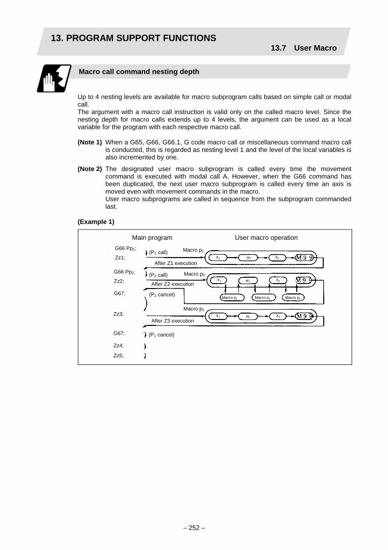
13. PROGRAM SUPPORT FUNCTIONS13.7 User Macro
– 252 –
Macro call command nesting depth
Up to 4 nesting levels are available for macro subprogram calls based on simple call or modal call. The argument with a macro call instruction is valid only on the called macro level. Since the nesting depth for macro calls extends up to 4 levels, the argument can be used as a local variable for the program with each respective macro call.
(Note 1) When a G65, G66, G66.1, G code macro call or miscellaneous command macro call
is conducted, this is regarded as nesting level 1 and the level of the local variables is also incremented by one.
(Note 2) The designated user macro subprogram is called every time the movement command is executed with modal call A. However, when the G66 command has been duplicated, the next user macro subprogram is called every time an axis is moved even with movement commands in the macro.
User macro subprograms are called in sequence from the subprogram commanded last.
(Example 1)
Main program User macro operation
G67; Zz4;
Zz5;
Zz3;
G67;
Zz2;
G66 Pp2;
Zz1;
G66 Pp1; (P1 call) Macro p1
After Z1 execution
(P2 call) Macro p2
After Z2 execution
Macro p1
(P2 cancel)
After Z3 execution
(P1 cancel)
X2 w1X1
X2 w1X1
Macro p1 Macro p1 Macro p1
X2 w1X1

13. PROGRAM SUPPORT FUNCTIONS13.7 User Macro
– 253 –
13.7.3 G code for macro
Function and purpose
G200 to G999 can be used as the user macro instruction. With this instruction, the execution of NC moves to the designated program.
G701 A__ B__ C__ ・・・ ;
Command format
G □ ;
□ 2 to 9 value
Detailed description
(1) The macro program number corresponding to the macro instruction is determined by the
last two digits after the G code and the value of the third digit of the set parameter. It is interpreted that there are no macros registered when the parameter is set to 0, and a program error (P34) will occur.
(2) The G code macro call returns to the main program with the subprogram's M99 command.
(3) Macro restrictions such as the argument address and local variables follow the macro call type corresponding commands (M99, G65, G66, G66.1) set by the respective parameters.
O 9701
M99 ;
~
~

13. PROGRAM SUPPORT FUNCTIONS13.7 User Macro
– 254 –
13.7.4 Variables
Function and purpose
Both the variable specifications and user macro specifications are required for the variables which are used with the user macros. The offset amounts of the local, common and system variables among the variables for this NC unit are retained even when the unit's power is turned OFF.
Multiple use of variables
When the user macro specifications apply, variable numbers can be turned into variables (multiple use of variables) or replaced by <formula>. Only one of the arithmetical (+, –, ×, ÷) operations can be conducted with <formula>.
(Example 1) Multiple use of variables
#1=10 #10=20 #20=30; # [# [#1]]=# [#10] from #1=10. #5=# [# [#1]]; # [#10]=#20 from #10=20. Therefore, #5=#20 or #5=30.
#1=10 #10=20 #20=30 # [#[#1]]=# [#10] from #1=10. #5=1000; # [#10]=#20 from #10=20. # [# [#1]]=#5; Therefore, #20=#5 or #20=1000.
(Example 2) Replacing variable numbers with <formula>
#10=5; # [#10+1]=1000; In which case, #6=1000. # [#10–1]=–1000; In which case, #4=–1000. # [#10∗3]=100; In which case, #15=100. # [#10/2]=–100; In which case, #3=–100.

13. PROGRAM SUPPORT FUNCTIONS13.7 User Macro
– 255 –
Undefined variables
Variables applying with the user macro specifications such as variables which have not been used even once after the power was turned ON or local variables not quoted by the G65, G66 or G66.1 commands can be used as <vacant>. Also, variables can forcibly be set to <vacant>. Variable #0 is always used as the <vacant> variable and nothing can be defined in the left-side member.
(1) Arithmetic expressions
#1 = #0 ; ・・・・・・・・・・・・・・ #1 = <vacant> #2 = #0 + 1 ;・・・・・・・・・・・ #2 = 1 #3 = 1 + #0 ;・・・・・・・・・・・ #3 = 1 #4 = #0∗10 ; ・・・・・・・・・・・ #4 = 0 #5 = #0 + #0 ;・・・・・・・・・・ #5 = 0
(2) Variable quotations When undefined variable only are quoted, they are ignored up to the address. When #1 = <Vacant>
G0 X#1 Z1000; ・・・・・・・・・・・・・・Equivalent to G0 Z1000; G0 X#1 + 10 Z1000; ・・・・・・・・・・Equivalent to G0 X10 Z1000;
(3) Conditional expressions (#0 is <vacant>.)
When #101 = <Vacant> When #101 = 0 #101 EQ #0
<Vacant> = <Vacant> established #101 EQ #0
0 = <Vacant> not established #101 NE 0
<Vacant> ≠ 0 established #101 NE 0
0 ≠ 0 not established #101 GE #0
<Vacant> ≥ 0 established #101 GE #0
0 ≥ <Vacant> established #101 GT 0
<Vacant> > 0 not established #101 GT 0
0 > 0 not established #101 LE #0
<Vacant> ≤ <Vacant> established #101 LE #0
0 ≤ <Vacant> established #101 LT0
<Vacant> < 0 not established #101 LT 0
0 < 0 not established
It should be borne in mind that <vacant> in an arithmetic expression is handled in the same way as "0". <Vacant> + <Vacant> = 0 <Vacant> + <Constant> = Constant <Constant> + <Vacant> = Constant

13. PROGRAM SUPPORT FUNCTIONS13.7 User Macro
– 256 –
13.7.5 Types of variables
Common variables (#100 to #149 and #500 to #549) (Example of type A)
These variables are used in common from any position. For details, refer to the section on the variable commands.
Local variables (#1 to #32)
These can be defined as an <argument> when a macro subprogram is called or used locally within main programs and subprograms. They can be duplicated regardless of the relationship existing between macros (up to 4 levels).
G65 Pp1 Lλ1 <argument> ;
p1 Program number λ1 Number of repetitions
The <argument> is assumed to be Aa1 Bb1 Cc1...... Zz1. The following table shows the correspondences between the addresses designated by <argument> and the local variable numbers used in the user macro main body.
Call command G65, G66 G66.1
Argument address
Local variable number
A #1 B #2 C #3 D #7 E #8 F #9 ∗ G #10 H #11 I #4 J #5 K #6 ∗ L #12 M #13 ∗ N #14 O #15 ∗ P #16
" " in the above table denotes an argument address which cannot be used. However, provided that the G66.1 mode has been established, an argument address denoted by the asterisk can be added for use. Note that there are no corresponding addresses for those marked with –.
Call commandG65, G66 G66.1
Argument address
Local variable number
Q #17 R #18 S #19 T #20 U #21 V #22 W #23 X #24 Y #25 Z #26
#27 #28 #29 #30 #31 #32

13. PROGRAM SUPPORT FUNCTIONS13.7 User Macro
– 257 –
(1) Local variables in subprograms can be defined by means of the <argument> designation during macro call. (Local variables can be used freely in those subprograms.)
Main program Subprogram (9900)
G65 P9900 A60. S100. F800;
M02;
#5 = #4010; G91 G01 X [#19∗COS [#1]] Y [#19∗SIN [#1]] F#9;
M99;
To subprogram
A (#1) = 60.000
F (#9) = 800
S (#19) = 100.000
Refer to the local variables andcontrol the movement, etc.
Local variablesset by argument
Local variable datatable
(2) Local variables can be used independently on each of the macro calls levels (4 levels). Local variables are also provided independently for the main program (macro level 0). Arguments cannot be used for the level 0 local variables.
Main (level 0)
#1=0.1 #2=0.2 #3=0.3; G65 P1 A1. B2. C3.; M02;
~ ~
O1 (macro level 1)
G65 P10 A10. B20. C30.;
M99;
O10 (macro level 2)
G65 P100 A100. B200.;
M99;
O100 (macro level 3)
M99;
Local variables (0) #1 0.100 #2 0.200 #3 0.300 #32
Local variables (1) A (#1) 0.100 B (#2) 0.200 C (#3) 0.300 D (#7) Z (#26) #32
~ ~
~ ~
~
~ ~ ~
~ ~
Local variables (2) A (#1) 10.100 B (#2) 20.200 C (#3) 30.300 D (#7) Z (#26) #32
Local variables (3) A (#1) 100.000 B (#2) 200.000 C (#3) Z (#26) #32
~ ~
~ ~
~ ~
The statuses of the local variables appear on the setting display unit. For details, refer to the Instruction Manual as well as to the sections covering the operation of the setting display unit and the local variables.
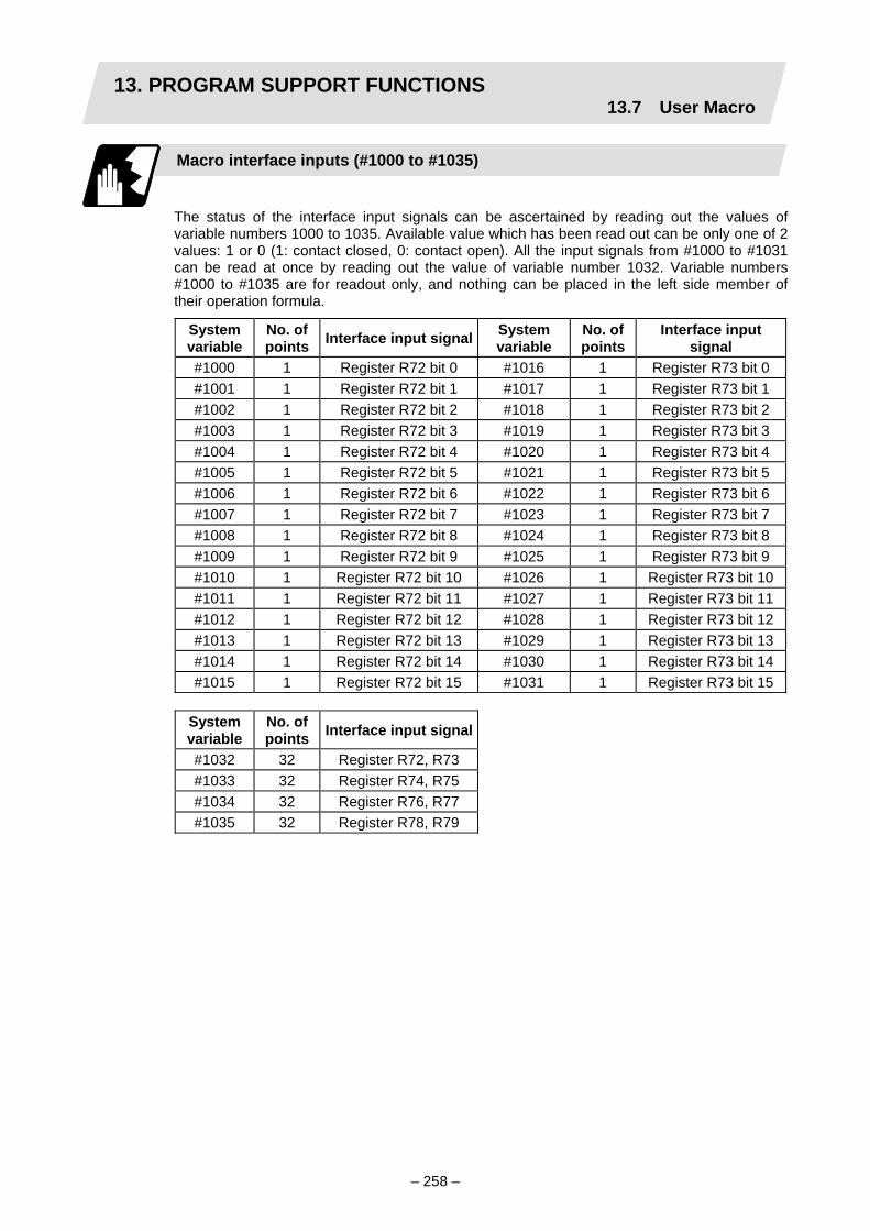
13. PROGRAM SUPPORT FUNCTIONS13.7 User Macro
– 258 –
Macro interface inputs (#1000 to #1035)
The status of the interface input signals can be ascertained by reading out the values of variable numbers 1000 to 1035. Available value which has been read out can be only one of 2 values: 1 or 0 (1: contact closed, 0: contact open). All the input signals from #1000 to #1031 can be read at once by reading out the value of variable number 1032. Variable numbers #1000 to #1035 are for readout only, and nothing can be placed in the left side member of their operation formula.
System variable
No. of points Interface input signal System
variable No. of points
Interface input signal
#1000 1 Register R72 bit 0 #1016 1 Register R73 bit 0 #1001 1 Register R72 bit 1 #1017 1 Register R73 bit 1 #1002 1 Register R72 bit 2 #1018 1 Register R73 bit 2 #1003 1 Register R72 bit 3 #1019 1 Register R73 bit 3 #1004 1 Register R72 bit 4 #1020 1 Register R73 bit 4 #1005 1 Register R72 bit 5 #1021 1 Register R73 bit 5 #1006 1 Register R72 bit 6 #1022 1 Register R73 bit 6 #1007 1 Register R72 bit 7 #1023 1 Register R73 bit 7 #1008 1 Register R72 bit 8 #1024 1 Register R73 bit 8 #1009 1 Register R72 bit 9 #1025 1 Register R73 bit 9 #1010 1 Register R72 bit 10 #1026 1 Register R73 bit 10#1011 1 Register R72 bit 11 #1027 1 Register R73 bit 11#1012 1 Register R72 bit 12 #1028 1 Register R73 bit 12#1013 1 Register R72 bit 13 #1029 1 Register R73 bit 13#1014 1 Register R72 bit 14 #1030 1 Register R73 bit 14#1015 1 Register R72 bit 15 #1031 1 Register R73 bit 15
System variable
No. of points Interface input signal
#1032 32 Register R72, R73 #1033 32 Register R74, R75 #1034 32 Register R76, R77 #1035 32 Register R78, R79
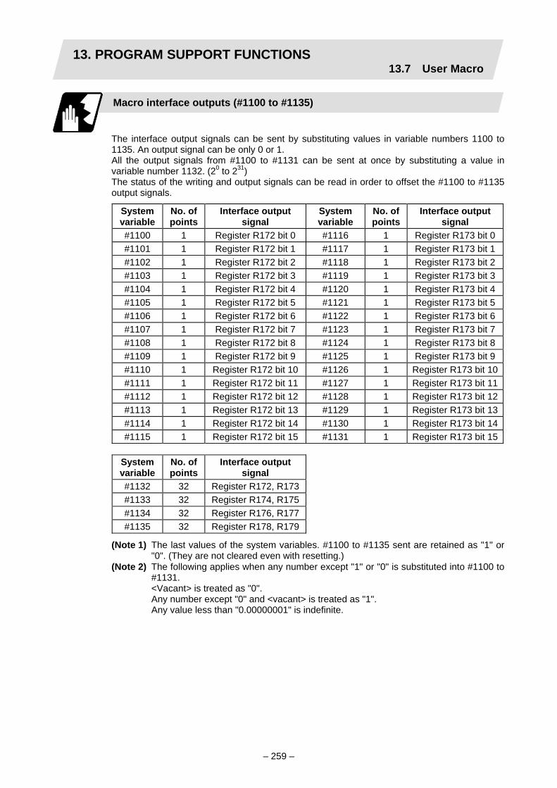
13. PROGRAM SUPPORT FUNCTIONS13.7 User Macro
– 259 –
Macro interface outputs (#1100 to #1135)
The interface output signals can be sent by substituting values in variable numbers 1100 to 1135. An output signal can be only 0 or 1. All the output signals from #1100 to #1131 can be sent at once by substituting a value in variable number 1132. (20 to 231) The status of the writing and output signals can be read in order to offset the #1100 to #1135 output signals.
System variable
No. of points
Interface output signal
System variable
No. of points
Interface output signal
#1100 1 Register R172 bit 0 #1116 1 Register R173 bit 0#1101 1 Register R172 bit 1 #1117 1 Register R173 bit 1#1102 1 Register R172 bit 2 #1118 1 Register R173 bit 2#1103 1 Register R172 bit 3 #1119 1 Register R173 bit 3#1104 1 Register R172 bit 4 #1120 1 Register R173 bit 4#1105 1 Register R172 bit 5 #1121 1 Register R173 bit 5#1106 1 Register R172 bit 6 #1122 1 Register R173 bit 6#1107 1 Register R172 bit 7 #1123 1 Register R173 bit 7#1108 1 Register R172 bit 8 #1124 1 Register R173 bit 8#1109 1 Register R172 bit 9 #1125 1 Register R173 bit 9#1110 1 Register R172 bit 10 #1126 1 Register R173 bit 10#1111 1 Register R172 bit 11 #1127 1 Register R173 bit 11#1112 1 Register R172 bit 12 #1128 1 Register R173 bit 12#1113 1 Register R172 bit 13 #1129 1 Register R173 bit 13#1114 1 Register R172 bit 14 #1130 1 Register R173 bit 14#1115 1 Register R172 bit 15 #1131 1 Register R173 bit 15
System variable
No. of points
Interface output signal
#1132 32 Register R172, R173#1133 32 Register R174, R175#1134 32 Register R176, R177#1135 32 Register R178, R179
(Note 1) The last values of the system variables. #1100 to #1135 sent are retained as "1" or "0". (They are not cleared even with resetting.)
(Note 2) The following applies when any number except "1" or "0" is substituted into #1100 to #1131.
<Vacant> is treated as "0". Any number except "0" and <vacant> is treated as "1". Any value less than "0.00000001" is indefinite.

13. PROGRAM SUPPORT FUNCTIONS13.7 User Macro
– 260 –
Input signal Output signal
Read only Read/write
Mac
ro in
stru
ctio
ns

13. PROGRAM SUPPORT FUNCTIONS13.7 User Macro
– 261 –
Tool offset (#10001 to or #2001 to)
Variable number range Contents #10001 to #10000 + n #2001 to #2000 + n 1st axis tool length offset amount #11001 to #11000 + n #2701 to #2700 + n 1st axis wear offset amount #12001 to #12000 + n ——— 3rd axis tool length offset amount #13001 to #13000 + n ——— 3rd axis wear offset amount #14001 to #14000 + n #2101 to #2100 + n 2nd axis tool length offset amount #15001 to #15000 + n #2801 to #2800 + n 2nd axis wear offset amount #16001 to #16000 + n #2201 to #2200 + n Nose R compensation amount #17001 to #17000 + n #2901 to #2900 + n Nose R wear compensation amount#18001 to #18000 + n #2301 to #2300 + n Tool nose point
Tool data can be read and values substituted using the variable numbers. Either the numbers in the #10000 order or #2000 order can be used. The last 3 digits of the variable numbers correspond to the tool offset number. The tool offset data are configured as data with a decimal point in the same way as for other variables. Consequently, this decimal point must be commanded when data below the decimal point is to be entered.
Programming example Common variables Tool offset data
#101 = 1000; #10001 = #101; #102 = #10001;
Afterexecution
#101 = 1000.0
#102 = 1000.0H = 1000.000
(Example 1) Calculation and tool offset data setting
Sensor
(Note) In this example no consideration is given to the delay in the skip sensor signal. #5001 is the X-axis start point position and #5061 is the X-axis skip coordinates, and
indicated is the position at which the skip signal is input while G31 is being executed.
~
G28 X0 T0101; M06; #1 = #5001; G00 X–200.; G31 X–50. F100; #10001 = #5061 – #1;
Zero point return Tool change (T0101) Start point storage Rapid traverse to safe position Skip measuring Measurement distance calculation and tool offset data setting

13. PROGRAM SUPPORT FUNCTIONS13.7 User Macro
– 262 –
Workpiece coordinate system offset (#5201 to #5323)
By using variable numbers 5201 to 5323, it is possible to read out the workpiece coordinate system offset data or to substitute values.
(Note) The number of axes which can be controlled differs according to the NC specifications. The last digit in the variable number corresponds to the control axis number.
Axis No.
Coordinate name
1st axis 2nd axis 3rd axis Remarks
External workpiece offset
#5201 #5202 #5203 External workpiece offset specifications are required.
G54 #5221 #5222 #5223G55 #5241 #5242 #5243G56 #5261 #5262 #5263G57 #5281 #5282 #5283G58 #5301 #5302 #5303G59 #5321 #5322 #5323
Workpiece coordinate system offset specifications are required.
(Example 1)
Basic machine coordinate system
External workpiece offset
Basic machine coordinate system
This is an example where the external workpiece offset values are added to the workpiece coordinate (G54, G55) system offset values without changing the position of the workpiece coordinate systems.
N1 G28 X0Z0; N2 #5221 = –20. #5223 = –20.; N3 G00 G54 X0Z0; N10 #5221 = –10. #5223 = –90.; N11 G00 G54 X0Z0; M02;
~ ~
G54 workpiece coordinate system defined by N2
G54 workpiece coordinate system defined by N10
N100 #5221 = #5221 + #5201; #5222 = #5222 + #5202; #5241 = #5241 + #5201; #5242 = #5242 + #5202; #5201 = 0 #5202 = 0;
~~
(Example 2)
Coordinate system after change
Coordinate system before change

13. PROGRAM SUPPORT FUNCTIONS13.7 User Macro
– 263 –
NC alarm (#3000)
The NC unit can be forcibly set to the alarm state by using variable number 3000.
Format
#3000 = 70 (CALL #PROGRAMMER #TEL #530);
70 Alarm number CALL #PROGRAMMER #TEL #530 Alarm message
Any alarm number from 1 to 9999 can be specified. The alarm message must be less than 31 characters long. The "P277 : Macro alarm message" appears in the <NC alarm> column on diagnosis page 1 while the alarm number and alarm message 70: (CALL #PROGRAMMER #TEL #530) is indicated in the <operator massage>.
Example of program (alarm when #1 = 0)
Stops withNC alarm
1F[#1NE0]GOTO100;#3000=70 (CALL #PROGRAMMER #TEL #530);
N100
<NC ALARM> DIAG 1.
P277 : Macro alarm message
<Operator message> CALL #PROGERAMMER #TEL #530 70
~~
(Note 1) Alarm number "0" is not displayed and any number exceeding "9999" cannot be indicated.
(Note 2) The characters "@" and "~" cannot be used in the alarm message. If the "@" or "~" character is used in the alarm message, a program error "P34" will occur.

13. PROGRAM SUPPORT FUNCTIONS13.7 User Macro
– 264 –
Integrating time (#3001, #3002)
The integrating time can be read when the power is turned ON or during automatic operation or automatic start or values can be substituted by using variable numbers 3001 and 3002.
Type Variable number Unit Contents when
power is turned ONInitialization of contents Count conditions
Power ON 3001 At all times while power is ON
Automatic start 3002
1ms Same as when power is turned OFF
Value substituted for variable In-automatic start
The integrating time returns to "0" in about 2.44 ×10ms (approximately 7.7 years).
G65 P9010T (allowable time) ms ;
~ ~
To subprogram
#3001=0; WHILE[#3001LE#20]DO1; END1; M99;
09010
Local variable Allowable time portion: DO1 to END1 is repeated and when allowable time is reached, operations jumps to M99.
Local variable
Entered in local variable #20 T#20 ———
~
Suppression of single block stop and miscellaneous function finish signal waiting (#3003)
By substituting the values below in variable number 3003, it is possible to suppress single block stop in the subsequent blocks or to advance to the next block without waiting for the miscellaneous function (M, S, T, B) finish signal (FIN).
Single block stop suppression Miscellaneous function finish signal not awaited Program check reverse run prohibitedSynchronization between systems function invalid∗ Not in use
(Note 1) #3003 is cleared to zero by resetting.
BIT7 BIT6 BIT5 BIT4 BIT3 BIT2 BIT1 BIT0 #3003

13. PROGRAM SUPPORT FUNCTIONS13.7 User Macro
– 265 –
Feed hold, feedrate override, G09 valid/invalid (#3004)
By substituting the values below in variable number 3004, it is possible to make the feed hold, feedrate override and G09 functions either valid or invalid in the subsequent blocks.
Automatic operation stop invalid Override invalid G09 check invalid Program check speed designation invalid Dry run invalid∗ Not in use
(Note 1) #3004 is cleared to zero by resetting.
(Note 2) The functions are valid when the above bits are "0" and invalid when they are "1".
Message display & stop (#3006)
By using variable number 3006, the message display is stopped after the previous block has been executed and, if the message display data have been commanded, then the corresponding message will be indicated.
Format
#3006=1 (TAKE FIVE);
TAKE FIVE Message
(Note 1) The message should not be longer than 31 characters and it should be enclosed within round parentheses.
(Note 2) #3006=1 is fixed to "1".
(Note 3) The characters "@" and "~" cannot be used in the message. If the "@" or "~" character is used in the message, a program error "P34" will occur.
Mirror image (#3007)
By reading variable number 3007, it is possible to ascertain the status of mirror image at a particular point in time for each axis. The axes correspond to the bits of #3007. Contents of each bit is indicated as follows.
0: Mirror image invalid 1: Mirror image valid
Bit 15 14 13 12 11 10 9 8 7 6 5 4 3 2 1 0nth axis 3 2 1
BIT7 BIT6 BIT5 BIT4 BIT3 BIT2 BIT1 BIT0 #3004

13. PROGRAM SUPPORT FUNCTIONS13.7 User Macro
– 266 –
G command medals (#4001 to #4021 and #4201 to #4221)
Using variable numbers 4001 to 4021, it is possible to read the modal commands which have been issued up to the block immediately before. Similarly, it is possible to read the medals in the block being executed with variable numbers #4201 to #4221.
Variable number Pre-read
block Execution
block Function
#4001 #4201 Interpolation mode: G00:0, G01:1, G02:2, G03:3, G33:33 #4002 #4202 Plane selection: G17:17, G18:18, G19:19 #4003 #4203 Absolute/incremental: G90:90, G91:91 #4004 #4204 Barrier check: G22:22, G23:23 #4005 #4205 Feed designation: G94:94, G95:95 #4006 #4206 Inch/metric: G20:20, G21:21 #4007 #4207 Tool nose radius compensation: G40:40, G41:41, G42:42, G46:46#4008 #4208 Second spindle control: G43:43, G44:44 #4009 #4209 Fixed cycle: G80:80, G73 to 79:73 to 79, G81 to G89:81 to 89 #4010 #4210 Return level: G98:98, G99:99 #4011 #4211 #4012 #4212 Workpiece coordinate system: G54 to G59:54 to 59 #4013 #4213 Acceleration/deceleration:G61 to G62:61 to 62, G64 to 64 #4014 #4214 Macro modal call: G66:66, G66.1:66.1, G67:67 #4015 #4215 Facing turret mirror image: G68:68, G69:69 #4016 #4216 #4017 #4217 Constant surface speed control: G96:96, G97:97 #4018 #4218 Balance cut: G14:14, G15:15 #4019 #4219 Milling: G12.1:12.1, G13.1:13.1 #4020 #4220 #4021 #4221
(Example) G28 X0 Z0; G00 X150. Z200; G65 P300 G02 W–30. K–15. F1000; M02; O300 #1=#4001; → Group 01 G modal (pre-read) #1 = 2.0 #2=#4201; → Group 01 G modal (now being executed) #2 = 0.0 G#1W#24; M99; %

13. PROGRAM SUPPORT FUNCTIONS13.7 User Macro
– 267 –
Other modals (#4101 to #4120 and #4301 to #4320)
Using variable numbers 4101 to 4120, it is possible to read the modal commands assigned up to the block immediately before. Similarly, it is possible to read the medals in the block being executed with variable numbers #4301 to #4320.
Variable number Pre-read Execution
Modal information
#4101 #4301 #4102 #4302 #4103 #4303 #4104 #4304 #4105 #4305 #4106 #4306 #4107 #4307 Tool wear offset No. #4108 #4308
#4109 #4309 Feedrate F (asynchronous)
#4110 #4310
Position information (#5001 to #5103)
The end point coordinate system, machine coordinate value, workpiece coordinate value, skip coordinate value, tool position offset amount and servo deviation amount in the previous block can be read using the variable numbers 5001 to 5103.
Position in- formation
Axis No.
End point coordinate of
block immediately before (program)
Machine coordinate
Workpiece coordinate
Skip coordinate (workpiece coordinate)
Tool position
offset amount
Servo deviation amount
1 #5001 #5021 #5041 #5061 #5081 #5101 2 #5002 #5022 #5042 #5062 #5082 #5102 3 #5003 #5023 #5043 #5063 #5083 #5103
Remarks (reading during movement) Yes No No Yes No Yes
(Note) The number of axes which can be controlled differs according to the NC specifications. The last digit of the variable number corresponds to the control axis number.
Variable number Position information #5121 Approach axis collision position #5122 Sampling designated axis collision position
Variable number Pre-read Execution
Modal information
#4111 #4311 #4112 #4312 #4113 #4313 Miscellaneous function M#4114 #4314 Sequence number N #4115 #4315 Program number O #4116 #4316 #4117 #4317 #4118 #4318 #4119 #4319 Spindle function S #4120 #4320 Tool function T

13. PROGRAM SUPPORT FUNCTIONS13.7 User Macro
– 268 –
Basic machine coordinate system
Workpiece coordinate system
Readcommand
[End point coordinates]
[Machine coordinates]
[Workpiece coordinates]
Workpiece coordinate system
Machine coordinate system
(1) The positions of the end point coordinates and skip coordinates are positions in the workpiece coordinate system.
(2) The end point coordinates, skip coordinates and servo deviation amounts can be read even during movement. However, it must first be checked that movement has stopped before reading the machine coordinates and workpiece coordinates.
(3) The position where the skip signal is turned ON in the G31 block is indicated for the skip coordinates. The end point position is indicated when the skip signal has not been turned ON. (For further details, refer to the section on tool length measurement.)
ReadCommand
Skip coordinates value
Gauge,etc.

13. PROGRAM SUPPORT FUNCTIONS13.7 User Macro
– 269 –
(4) The tool nose position where the tool offset and other such factors are not considered is indicated as the end point position. The tool reference point position with consideration given to tool offset is indicated for the machine coordinates, workpiece coordinates and skip coordinates.
Skip signal
F (feedrate)
[Workpiececoordinates][Input coordinates of skip signal]
[Machine coordinates]
Workpiece coordinatesystem
Machine coordinatesystem
The position of the skip signal input coordinate value is the position in the workpiece coordinate system. The coordinate value in variable numbers #5061 to #5063 memorize the moments when the skip input signal during movement was input and so they can be read at any subsequent time. For further details, reference should be made to the section on the "skip" function.
For " ", check stop and then proceed to read. For " ", reading is possible during movement.

13. PROGRAM SUPPORT FUNCTIONS13.7 User Macro
– 270 –
Variable name setting and quotation
Any name (variable name) can be given to common variables #500 to #519. It must be composed of not more than 7 alphanumerics and it must begin with an alphabetic character.
Format
SETVNn[NAME1,NAME2,・・・・・];
n Head number of variable which assigns name NAME1 #n name (variable name) NAME2 #n + 1 name (variable name)
Variable names are separated by a comma ",".
Detailed description (1) Once variable names have been set, they will not be cleared even when the power is
turned OFF.
(2) Variables in programs can be quoted by their variable names. In cases like this, the variables should be enclosed in square parentheses.
(Example 1) G01X[#POINT1];
(3) The variable numbers, data and variable names appear on the CRT screen of the setting display unit.
(Example 2) Program... SETVN500[A234567, DIST, TOOL25];
[Common variables]
#500 –12345.678 A234567 #501 5670.000 DIST #502 –156.500 TOOL25
#518 10.000 NUMBER
Common variable #(502)DATA(–156.5) NAME (TOOL25)
(Note) Do not include character strings (SIN, COS, etc.) used for operation commands, etc. in the variable name.

13. PROGRAM SUPPORT FUNCTIONS13.7 User Macro
– 271 –
13.7.6 Operation commands
A variety of operations can be performed between variables.
Command format
#i=<formula>;
<Formula> is a combination of constants, variables, functions and operators. Constants can be used instead of #j and #k below.
(1) Definition and substitution of variables
#i = #j Definition, substitution
(2) Addition operation
#i = #j + #k #i = #j – #k #i = #j OR #k #i = #j XOR #k
Addition Subtraction Logical sum (at every bit of 32 bits) Exclusive OR (at every bit of 32 bits)
(3) Multiplication operation
#i = #j ∗ #k #i = #j / #k #i = #j MOD #k #i = #j AND #k
Multiplication Division Remainder Logical product (at every bit of 32 bits)
(4) Functions
#i = SIN [#k] #i = COS [#k] #i = TAN [#k] #i = ATAN [#k] #i = ACOS [#k] #i = SQRT [#k] #i = ABS [#k] #i = BIN [#k] #i = BCD [#k] #i = ROUND [#k] #i = FIX [#k] #i = FUP [#k] #i = LN [#k] #i = EXP [#k]
Sine Cosine Tangent (sinθ/cosθ used for tanθ) Arctangent (ATAN or ATN may be used) Arccosine Square root (SQRT or SQR may be used) Absolute value Conversion from BCD to BINARY Conversion from BINARY to BCD Rounding off (ROUND or RND may be used) Discard fractions less than 1 Add for fractions less than 1 Natural logarithm Exponent with e (=2.718...) as bottom
(Note 1) A value without a decimal point is basically treats as a value with a decimal point at the end (1 = 1.000).
(Note 2) Offset amounts from #10001 and workpiece coordinate system offset values from #5201 are handled as data with a decimal] point. Consequently, data with a decimal point will be produced even when data without a decimal point have been defined in the variable numbers.
(Example)
(Note 3) The <formula> after a function must be enclosed in the square parentheses.
#101 = 1000 ; #10001 = #101 ; #102 = #10001 ;
#101 1000.000 #102 1000.000
Common variables after execution

13. PROGRAM SUPPORT FUNCTIONS13.7 User Macro
– 272 –
Sequence of operations
(1) The sequence of the operations (1) to (3) is, respectively, the functions followed by the
multiplication operation followed in turn by the addition operation.
#101=#111+#112∗SIN[#113] (1) Function (2) Multiplication operation (3) Addition operation
(2) The part to be given priority in the operation sequence should be enclosed in brackets. Up
to 5 pairs of such brackets including those for the functions may be used.
#101=SQRT [ [ [#111 – #112] ∗ SIN [#113] + [#114] ∗ #115] ;
Examples of operation commands
(1) Main program
and argument designation
G65P100A10B20.; #101 = 100.000 #102 = 200.000;
#1 #2 #101 #102
10.00020.000
100.000200.000
(2) Definition and substitution
#1 = 1000 #2 = 1000. #3 = #101 #4 = #102 #5 = #5041
#1 #2 #3 #4 #5
1000.0001000.000
100.000200.000–10.000
(3) Addition and subtraction (+, –)
#11 = #1+1000 #12 = #2–50. #13 = #101+#1 #14 = #5041–3. #15 = #5041+#102
#11 #12 #13 #14 #15
2000.000950.000
1100.000–13.000190.000
#3 = 01100100 14 = 00001110
(4) Logical sum (OR)
#3 = 100 #4 = #3OR14
#4 = 01101110 = 110 #3 = 01100100 14 = 00001110
(5) Exclusive OR (XOR)
#3 = 100 #4 = #3XOR14
#4 = 01101010 = 106 (6) Multiplication
and division (∗, /)
#21 = 100∗100 #22 = 100.∗100 #23 = 100∗100 #24 = 100.∗100. #25 = 100/100 #26 = 100./100. #27 = 100/100. #28 = 100./100. #29 = 5041∗#101 #30 = 5041/#102
#21 #22 #23 #24 #25 #26 #27 #28 #29 #30
10000.00010000.00010000.00010000.000
1.0001.0001.0001.000
–1000.000–0.050
First pair of brackets
Second pair of brackets
Third pair of brackets
From common variables
From offset amount

13. PROGRAM SUPPORT FUNCTIONS13.7 User Macro
– 273 –
Remainder
(MOD) #31 = #19MOD#20 #19/#20 = 48/9 = 5 with 3 over
#9 = 100 #10 = #9AND15
#9 = 01100100 15 = 00001111
(7) Logical product (AND) #10 = 00000100 = 4
(8) Sin (SIN) #501 = SIN [60] #502 = SIN [60.] #503 = 1000∗SIN [60] #504 = 1000∗SIN [60.] #505 = 1000.∗SIN [60] #506 = 1000.∗SIN [60.] (Note) SIN [60] is equivalent to SIN
[60.]
#501 #502 #503 #504 #505 #506
0.860 0.860
866.025 866.025 866.025 866.025
(9) Cosine (COS)
#541 = COS [45] #542 = COS [45.] #543 = 1000∗COS [45] #544 = 1000∗COS [45.] #545 = 1000.∗COS [45] #546 = 1000.∗COS [45.] (Note) COS [45] is equivalent to COS
[45.]
#541 #542 #543 #544 #545 #546
0.707 0.707
707.107 707.107 707.107 707.107
(10) Tangent (TAN)
#551 = TAN [60] #552 = TAN [60.] #553 = 1000∗TAN [60] #554 = 1000∗TAN [60.] #555 = 1000.∗TAN [60] #556 = 1000.∗TAN [60.] (Note) TAN [60] is equivalent to TAN
[60.]
#551 #552 #553 #554 #555 #556
1.732 1.732
1732.051 1732.051 1732.051 1732.051
(11) Arctangent (ATAN or ATN)
#561 = ATAN [173205/100000] #562 = ATAN [173205/100.] #563 = ATAN [173.205/100000] #564 = ATAN [173.205/100.] #565 = ATAN [1.732]
#561 #562 #563 #564 #565
60.000 60.000 60.000 60.000 59.999
(12) Arccosine (ACOS)
#521 = ACOS [100./141.421] #522 = ACOS [100./141.421] #523 = ACOS [1000./1414.213] #524 = ACOS [10./14.142] #525 = ACOS [0.707]
#521 #522 #523 #524 #525
45.000 45.000 45.000 44.999 45.009
(13) Square root (SQR or SQRT)
#571 = SQRT [1000] #572 = SQRT [1000.] #573 = SQRT [10.∗10.+20.∗20.] #574 = SQRT [#14∗#14 + #15∗#15] (Note) In order to increase the
accuracy, proceed with the operation inside parentheses.
#571 #572 #573 #574
31.623 31.623 22.361
190.444
(14) Absolute value (ABS)
#576 = –1000 #577 = ABS [#576] #3 = 70. #4 = –50. #580 = ABS [#4 – #3]
#576 #577 #580
–1000.000 1000.000
120.000
(15) BIN, BCD #1 = 100 #11 = BIN [#1] #12 = BCD [#1]
#11 #12
64
256

13. PROGRAM SUPPORT FUNCTIONS13.7 User Macro
– 274 –
(16) Rounding off
(ROUND or RND)
#21 = ROUND [14/3] #22 = ROUND [14./3] #23 = ROUND [14/3.] #24 = ROUND [14./3.] #25 = ROUND [–14/3] #26 = ROUND [–14./3] #27 = ROUND [–14/3.] #28 = ROUND [–14./3.]
#21 #22 #23 #24 #25 #26 #27 #28
5 5 5 5
–5 –5 –5 –5
(17) Discarding fractions below decimal point (FIX)
#21 = FIX [14/3] #22 = FIX [14./3] #23 = FIX [14/3.] #24 = FIX [14./3.] #25 = FIX [–14/3] #26 = FIX [–14./3] #27 = FIX [–14/3.] #28 = FIX [–14./3.]
#21 #22 #23 #24 #25 #26 #27 #28
4.000 4.000 4.000 4.000
–4.000 –4.000 –4.000 –4.000
(18) Adding fractions less than 1 (FUP)
#21 = FUP [14/3] #22 = FUP [14./3] #23 = FUP [14/3.] #24 = FUP [14./3.] #25 = FUP [–14/3] #26 = FUP [–14./3] #27 = FUP [–14/3.] #28 = FUP [–14./3.]
#21 #22 #23 #24 #25 #26 #27 #28
5.000 5.000 5.000 5.000
–5.000 –5.000 –5.000 –5.000
(19) Natural logarithms (LN)
#101 = LN [5] #102 = LN [0.5] #103 = LN [–5]
#101 #102 Error
1.609 –0.693 "P282"
(20) Exponents (EXP)
#104 = EXP [2] #105 = EXP [1] #106 = EXP [–2]
#104 #105 #106
7.389 2.718 0.135

13. PROGRAM SUPPORT FUNCTIONS13.7 User Macro
– 275 –
Operation accuracy
As shown in the following table errors will be generated when performing operations once and these errors will be accumulated by repeating the operations.
Operation format Average error Maximum error Type of error a = b + c a = b – c 2.33 × 10⁻¹⁰ 5.32 × 10⁻¹⁰ Min. | | , | |
a = b∗c 1.55 × 10⁻¹⁰ 4.66 × 10⁻¹⁰ a = b/c 4.66 × 10⁻¹⁰ 1.86 × 10⁻⁹ a = b 1.24 × 10⁻⁹ 3.73 × 10⁻⁹
Relative error | |
a = SIN [b] a = COS [b] 5.0 × 10⁻⁹ 1.0 × 10⁻⁸
a = ATAN [b/c] 1.8 × 10⁻⁶ 3.6 × 10⁻⁶
Absolute error | ε | °
(Note 1) SIN/COS is calculated for the function TAN.
Notes on reduced accuracy
(1) Addition and subtraction
It should be noted that when absolute values are used subtractively in addition or subtraction, the relative error cannot be kept below 10–8. For instance, it is assumed that the real value produced as the operation calculation result of #10 and #20 are as follows (these value cannot be substituted directly):
#10 = 2345678988888.888 #20 = 2345678901234.567
Performing #10 – #20 will not produce #10 – #20 = 87654.321. There are 8 decimal digits in the variables and so the values of #10 and #20 will be as follows (strictly speaking, the internal values will differ somewhat from the value below because they are binary numbers):
#10 = 2345679000000.000 #20 = 2345678900000.000
Consequently, #10 – #20 = 100000.000 will generate a large error.
(2) Logical relation EQ, NE, GT, LT, GE and LE are basically the same as addition and subtraction and so care should be taken with errors. For instance, to determine whether or not #10 and #20 are equal in the above example:
IF[#10EQ#20] It is not always possible to provide proper evaluation because of the above-mentioned error. Therefore when the error is evaluated as in the following expression:
IF [ABS [#10–#20]LT200000] and the difference between #10 and #20 falls within the designated range error, both values should be considered equal.
(3) Trigonometric functions
Absolute errors are guaranteed with trigonometric functions but since the relative error is not under 10–8, care should be taken when dividing or multiplying after having used a trigonometric function.
ε b
εc
ε a

13. PROGRAM SUPPORT FUNCTIONS13.7 User Macro
– 276 –
13.7.7 Control commands
The flow of programs can be controlled by IF ~ GOTO ~ and WHILE ~ DO ~.
Branching
Format
IF [conditional expression] GOTO n ; (where n = sequence number in the program)
When the condition is satisfied, control branches to "n" and when it is not satisfied, the next block is executed. IF [conditional expression] can be omitted and, when it is, control passes to "n" unconditionally. The following types of [conditional expressions] are available.
#i EQ #j = When #i and #j are equal #i NE #j ≠ When #i and #j are not equal #i GT #j > When #i is greater than #j #i LT #j < When #i is less than #j #i GE #j ≥ When #i is #j or more #i LE #j ≤ When #i is #j or less
"n" of "GOTO n" must always be in the same program. Alarm "P231" will result if it is not. A formula or variable can be used instead of #i, #j and "n". In the block with sequence number "n" which will be executed after a "GOTO n" command, the sequence number Nn must always be at the head of the block. Otherwise, alarm "P231" will result. If "/" is at the head of the block and Nn follows, control can be branched to the sequence number.
N10 #22=#20 #23=#21; IF[#2EQ1]GOTO100; #22=#20–#3; #23=#21–#4; N100 X#22 Z#23; #1=#1+#1;
~~
~
Branching to N100when content of #2 is 1
Bra
nch
sear
ch
N100
Branchsearch
WithN10
Tohead
(Note) When the sequence number of the branch destination is searched, the search is conducted up to the end of the program (% code) from the block following "IF..... ;" and if it is not found, it is conducted up to the block before "IF ..... ;". Therefore, branch searches in the opposite direction to the program flow will take longer to execute compared with branch searches in the forward direction.

13. PROGRAM SUPPORT FUNCTIONS13.7 User Macro
– 277 –
Repetition
Format
WHILE [conditional expression] DOm ; (m =1, 2, 3 ..... 127) END m ;
While the conditional expression is established, the blocks from the following block to ENDm are repeatedly executed; when it is not established, execution moves to the block after ENDm. DOm may come before WHILE. "WHILE [conditional expression] DOm" and "ENDm" must be used as a pair. If "WHILE [conditional expression]" is omitted, these blocks will be repeatedly in infinitum. The repeating identification numbers range from 1 to 127 (DO1, DO2, DO3, ..... DO127). Up to 27 nesting levels can be used.
(1) Same identification number can be used any
number of times.
(2) Any number may be used for the WHILE~ DOm identification number.
(3) Up to 27 nesting levels for WHILE~Dom. "m" is any number form 1 to 127 for the nesting depth. (Note) With nesting, "m" which has been used once cannot be used.
(4) The number of WHILE~DOm nesting levels cannot exceed 27.
(Note) When the fixed cycle is used during the WHILE~DOm interval, the WHILE~DOm nesting levels will be less than 27.
~
WHILE ~ DO1; END1;
WHILE ~ DO1; END1;
Possible
Possible
WHILE ~ DO1; END1;
~
WHILE ~ DO3; END3;
~~
WHILE ~ DO2; END2;
~~
WHILE ~ DO1; END1;
~~
Possible
WHILE ~ DO1;
WHILE ~ DO2;
WHILE ~ DO3;
WHILE ~ DO28;
END3;
END28;
~~
~~
END2;:
END1;
~
:
Not possible
Possible
DO2
DO1
DO27
END1;
WHILE ~ DO1;
WHILE ~ DO2;
WHILE~DO27;
END2;
END27;
:
:

13. PROGRAM SUPPORT FUNCTIONS13.7 User Macro
– 278 –
(5) WHILE ~ DOm must be designated first and
ENDm last.
(6) WHILE ~ DOm and ENDm must correspond on a 1:1 (pairing) basis in the same program.
(7) Two WHILE ~ DOm’s must not overlap.
(8) Branching externally is possible from the WHILE ~ DOm range.
(9) No branching is possible inside WHILE ~ DOm.
(10) Subprograms can be called by M98, G65 or G66 between WHILE ~ DOm’s.
(11) Calls can be initiated by G65 or G66 between WHILE ~ DOm’s and commands can be issued again from 1. Up to 27 nesting levels are possible for the main program and subprograms.
(12) A program error results with M99 unless WHILE and END are paired within the subprograms (including macro programs).
END1;
WHILE ~ DO1;
Not possible
Not possible
WHILE ~ DO1;
END1;
WHILE ~ DO1;
Nn;
END2;
END1;
WHILE ~ DO2;
WHILE ~ DO1;
Not possible
WHILE ~ DO1; IF ~ GOTOn; END1; Possible
Not possible Not
possible
WHILE ~ DO1; Nn END1;
IF ~ GOTOn;
WHILE ~ DO1 ; Nn END 1 ;
WHILE ~ DO1; IF ~ GOTOn; END1;
~ ~
~
WHILE ~ DO1; END1; M99;
WHILE ~ DO1; G65 P100; END1;
SubprogramMain program
Pos
sibl
e
To subprogram
M02;
~ ~
~ ~
WHILE ~ DO1; M99;
M99 P100; M02;
Subprogram Main program
To subprogram
DOn ENDn illegal usage.
~ ~
~ ~
WHILE ~ DO2; END 2; M99;
WHILE ~ DO1; G65 P100; END1;
SubprogramMain program
Pos
sibl
e
To subprogram
~ ~
M02;

13. PROGRAM SUPPORT FUNCTIONS13.7 User Macro
– 279 –
13.7.8 Precautions
Precautions
(1) When the user macro commands are employed, it is possible to use the M, S, T and other
NC control commands together with the operation, decision, branching and other macro commands for creating the machining programs. When the former commands are made into NC executable statements and the latter commands into macro statements, the macro statement processing should be accomplished as quickly as possible in order to minimize the machining time, because such processing is not directly related to machine control. As a result, the parameter (control parameter "Macro single") can be decided upon and the macro statements can be processed in parallel with the execution of the NC executable statement. (The parameter can be set OFF during normal machining to process all the macro statements together or set ON during a program check to execute the macro statements block by block. This enables the setting to be made in accordance with the intended objective in mind.)
Example of program
G91 G28 X0 Z0;
G92 X0 Z0;
G00 X–100. Z–100.;
#101=100.∗COS [210,];
#103=100.∗SIN [210.];
G01 X#101 Z#103 F800;
Macro statements are:
(a) Operation commands (blocks including "=")
(b) Control commands (blocks including GOTO, DO~END, etc.)
(c) Macro call commands (including macro calls based on G codes and cancel command (G65, G66, G66.1, G67))
NC statements are all those statements which are not macro statements.
Macro statement

13. PROGRAM SUPPORT FUNCTIONS13.7 User Macro
– 280 –
Flow of processing
Macro single OFF
Program analysis
Executing block
(1) (2) (4)(5)(6) (3)
(1) (2) (4)(5)(6) (3)
Macro single
ON
(1) (2) (3)
(1) (2) (3)
(4) (5) (6)
(4) (5) (6)
Program analysis
Executing block
Machining program display
Macro single OFF
[Executing] N3 G00 X–100. Z–100.;[Next command] N6 G01 X#101 Z#103 F800;
N4, N5 and N6 are processed in parallel with the control of the NC executable statement of N3. N6 is an NC executable statement and so it is displayed as the next command. If the N4, N5 and N6 analysis is in time during N3 control, the machine movement will be continuously controlled.
Macro single
ON
[Executing] N3 G00 X–100. Z–100.;[Next command] N4 #101=100.∗COS[210.];
N4 is processed in parallel with the control of the NC executable statement of N3, and it is displayed as the next command. N5 and N6 are analyzed and N6 is executed after N3 has finished, and so the machine control is held on standby during the N5 and N6 analysis time.

13. PROGRAM SUPPORT FUNCTIONS13.8 Double-Turret Mirror Image
– 281 –
13.8 Double-Turret Mirror Image; G68, G69
Function and purpose
With machines in which the base turret and facing turret are integrated, this function enables the workpiece to be cut by the tools on the facing turret using the programs prepared at the base turret side. (See figure below). The distance between the two turrets is set beforehand with the parameter.
Command format
G68; G69;
G68 Double-turret mirror image ON G69 Double-turret mirror image Cancel
When the G68 command is issued, the subsequent programmed coordinate systems are shifted to the facing turret side and the movement direction of the X axis is made the opposite of that commanded by the program. When the G69 command is issued, the subsequent programmed coordinate systems are returned to the base turret side.
Programmed path
Facing turret path(mirror image ON)
Z
X
(G69)
(G68)
Base turret
Facing turret
Parameter fordistance betweenturrets (radial value,X axis only)

13. PROGRAM SUPPORT FUNCTIONS13.8 Double-Turret Mirror Image
– 282 –
Program and example of operation
(1) Example of operation by absolute value command
T0101; G00 X10. Z0.; G01 Z-40. F400; X20.;
Selection of base turret
Machining by base turret ・・・・・・・・・・・A
G68; T0202; G00 X20. Z-40.; G01 X20. Z-80. F200; X30.;
Double-turret mirror image ON Selection of facing turret ・・・・・・・ [1]
Machining by facing turret ・・・・・・・・・・・B
G69; T0101; G00 X30. Z-80.; G01 X30. Z-120. F400;
Double-turret mirror image cancel Selection of base turret ・・・・・・・ [2]
Machining by base turret ・・・・・・・・・・・C
X
Z
Base turret
Facing turret
2.
2.’
C
B1.’
1.
A
A value determined from the turret interval parameter is added for movement by the first X-axis command issued after the double-turret mirror image is turned ON. In the above operation example, program [1] block causes movement 1 to 1’. Similarly, a value determined from the turret interval parameter is subtracted for movement by the first X-axis command issued after the double-turret mirror image is canceled. In the above operation example, program [2] block causes movement from 2 to 2’.

13. PROGRAM SUPPORT FUNCTIONS13.8 Double-Turret Mirror Image
– 283 –
(2) Example of operation by incremental value command
T0101; G00 X0. Z0.; G01 Z-40. F400;
X20.;
Selection of base turret
Machining by base turret ・・・・・・・・・・・A
G68; T0202; G00 U-10. W0.; G01 X20. Z-80. F200; X30.;
Double-turret mirror image ON Selection of facing turret ・・・・・・・ [1]’
Machining by facing turret ・・・・・・・・・・・B
G69; T0101; G00 U-10. W0.; G01 X30. Z-120. F400;
Double-turret mirror image cancel Selection of base turret ・・・・・・・ [2]’
Machining by base turret ・・・・・・・・・・・C
X
Z
Base turret
Facing turret
2.
2.’C
B
1.’
1.
A
A incremental value command issued after the double-turret mirror image is turned ON causes movement by the amount of the X-axis movement in the opposite direction specified by the program command. Block [1]’ made by changing program [1] in "(1) Example of operation by absolute value command" to an incremental command causes the tool to move +10. by reversing –10. In the above operation example, the tool moves from 1 to 1’. The same applies to an incremental value command issued after the double-turret mirror image is canceled. Block [2]’ made by changing program [2] in "(1) Example of operation by absolute value command" to an incremental command causes the tool to move –10. In the above operation example, the tool moves from 2 to 2’.

13. PROGRAM SUPPORT FUNCTIONS13.8 Double-Turret Mirror Image
– 284 –
Turret offset amount
(1) Tool length offset amount
The tool length is the distance from the tool nose to the tool length base point. This definition is the same for the facing turret. However, the offset amount setting differs according to the position of the tool length base point, as shown below. (The settings are approached from the types in the table below.)
Type A Type B Type C Workpiece zero point Workpiece face center Workpiece face center Workpiece face center
Tool length base point Turret base points Base turret base point Workpiece face center
Distance between turrets
Distance between base points of both turrets (radius value)
0 0
Workpiece offset
Workpiece zero point – tool length base point of base turret
Workpiece zero point – tool length base point of base turret
0
Tool length Tool length base point – tool nose position
Tool length base point – tool nose position
Tool length base point – tool nose position
Outline drawings
Workpiecezero point
Workpieceoffset
Tool length
Distance between turrets
Toollength
Base turret
Facing turret
Turret base point
Turret base point
Workpiecezero point
Workpieceoffset
Toollength
Base turret
Facing turret
Turret base point
Toollength
Turret base point
Workpiecezero point
Tool length
Tool length
Turret base point
Base turret
Facing turret
Turret base point
The above outline drawings apply when the machine parameter (base specifications parameter) "mirrA" is 0. If it is 1, the value is set with the tool of the facing turret in the same direction as the tool of the base turret. At this time, the tool length base point is the tool length base point of the base turret. When "mirrA" is 1, the sign for the X-axis tool length wear amount for the facing tool is reversed and the tool nose point is set to the opposite side (for instance, 2 → 3). When tool length measurement is executed with "mirrA" as 0, the data will be accepted with "mirrA" as 0.
(Setting examples)
mirrA=0 mirrA=1 X Z X Z
Workpiece offset –120. –110. –120. –110. Tool length of base turret 80. 35. 80. 35. Tool wear amount of base turret –20. –5. –20. –5. Tool nose point of base turret 3 3 Tool length of facing turret 150. 40. 120. 40. Tool wear amount of facing turret –20. –5. –20. –5. Tool nose point of facing turret 2 3 Distance between turret 0 0

13. PROGRAM SUPPORT FUNCTIONS13.8 Double-Turret Mirror Image
– 285 –
(2) Tool length wear offset amount The tool length wear offset amount is the distance from the current tool nose to the original tool nose. The original tool nose is that value applying when the tool length offset amount was set.
(3) Tool nose point with nose R compensation
The tool nose point with tool nose R compensation is as follows. It is common for both the base and facing turrets.
Tool wear offset amount and nose R tool nose point
–X
Base turret side
X
Base tool
0
12
3 4
5
6
7
8
ZBase tool
Wearamount
12 6
0 57
3 48
Wearamount
(4) Distance between turrets
The distance between the turrets is the distance from the tool length base point of the facing turret to the tool length base point of the base turret. It is set by parameter only for the X axis. "0" is set when the tool length base point is common.
Machine parameter (Base specifications parameter) mirofs Setting range: 0 to 99999.999 (mm) (radial value)

13. PROGRAM SUPPORT FUNCTIONS13.9 Corner Chamfering, Corner Rounding Function I
– 286 –
13.9 Corner Chamfering, Corner Rounding Function I
Chamfering at any angle or corner rounding is performed automatically by adding ",C_" or ",R_" to the end of the block to be commanded first among those command blocks which shape the corner with lines only.
13.9.1 Corner chamfering (,C_ )
Function and purpose
The corner is chamfered in such a way that the positions produced by subtracting the lengths commanded by ",C_" from the hypothetical starting and final corners which would apply if no chamfering were to be performed are connected.
Command format
N100 G01 X__ Z__ ,C__ ; N200 G01 X__ Z__ ;
C__ Length up to chamfering starting point or end point from hypothetical corner
Chamfering is performed at the point where N100 and N200 intersect.
Example of program
G01 W100. ,C10. F100; U280. W100.;
Chamferingend point
Hypothetical cornerintersection
Chamfering start point
Z axis
X axis

13. PROGRAM SUPPORT FUNCTIONS13.9 Corner Chamfering, Corner Rounding Function I
– 287 –
Detailed description
(1) The start point of the block following the corner chamfering serves as the hypothetical
corner intersection.
(2) When the comma in ",C" is not present, it is handled as a C command.
(3) When both "C_" and "R_" are commanded in the same block, the latter command is valid.
(4) Tool offset is calculated for the shape which has already been subjected to corner chamfering.
(5) Program error "P382" results when the block following the corner chamfering block does not contain a linear command.
(6) Program error "P383" results when the movement amount in the corner chamfering block is less than the chamfering amount.
(7) Program error "P384" results when the movement amount in the block following the corner chamfering block is less than the chamfering amount.
(8) When corner chamfering I is commanded, 2 blocks are pre-read for calculating the intersection.

13. PROGRAM SUPPORT FUNCTIONS13.9 Corner Chamfering, Corner Rounding Function I
– 288 –
13.9.2 Corner rounding (,R_ )
Function and purpose
The imaginary corner, which would exist if the corner were not to be rounded, is rounded with the arc having the radius which is commanded by ",R_" only when configured of linear lines.
Command format
N100 G01 X__ Z__ ,R__ ; N200 G01 X__ Z__ ;
R__ Circular radius of corner rounding
Rounding is performed at the point where N100 and N200 intersect.
Example of program
G01 W100. ,R10. F100; U280. W100.;
Corner rounding end point
Corner rounding start point
Hypothetical corner intersection
X i
Z axis

13. PROGRAM SUPPORT FUNCTIONS13.9 Corner Chamfering, Corner Rounding Function I
– 289 –
Detailed description
(1) The start point of the block following the corner rounding serves as the hypothetical corner
intersection.
(2) When the comma in ",R" is not present, it is handled as an R command.
(3) When both "C_" and "R_" are commanded in the same block, the latter command is valid.
(4) Tool offset is calculated for the shape which has already been subjected to corner rounding.
(5) Program error "P382" results when the block following the corner rounding block does not contain a linear command.
(6) Program error "P383" results when the movement amount in the corner rounding block is less than the R value.
(7) Program error "P384" results when the movement amount in the block following the corner rounding block is less than the R value.
(8) When corner rounding I is commanded, 2 blocks are pre-read for calculating the contact.

13. PROGRAM SUPPORT FUNCTIONS13.10 Corner Chamfering, Corner Rounding Function II
– 290 –
13.10 Corner Chamfering, Corner Rounding Function II
This function enables chamfering and corner rounding by adding ",C_" or ",R_" after the first commanded block among the command blocks which configure the corner by an circular or line with any continuous angle. Chamfering and corner rounding can be conducted with both absolute and incremental commands.
13.10.1 Corner chamfering (,C_)
Function and purpose
Corner chamfering is conducted by issuing the ",C_" command in the first block among 2 blocks including a continuous arc. In the case of a circular, the length of the chord applies.
Command format
N100 G03 X__ Z__ I__ K__ ,C_ ; N200 G01 X__ Z__ ;
C__ Length from hypothetical corner to start or end point of chamfering
Chamfering is performed at the intersection between N100 and N200,
Example of program
(1) Linear – circular Absolute value commands
N1 G28 XZ; N2 G00 X50. Z100.; N3 G01 X150. Z50. ,C20. F100; N4 G02 X50. Z0 I0 K–50.; :
Incremental value commands
N1 G28 XZ; N2 G00 U25. W100.; N3 G01 U50. W–50. ,C20. F100; N4 G02 U–50. W–50. I0 K–50.; :
Hypothetical corner intersection
(Unit: mm)

13. PROGRAM SUPPORT FUNCTIONS13.10 Corner Chamfering, Corner Rounding Function II
– 291 –
(2) Circular – circular Absolute value commands
N1 G28 X Z; N2 G00 X20. Z140.; N3 G02 X100. Z60. I100. K0. ,C20. F100; N4 X60. Z0 I80. K–60.; :
Incremental value commands
N1 G28 X Z; N2 G00 U10. W140.; N3 G02 U40. W–80. R100. ,C20. F100; N4 U–20. W–60. I80. K–60.; :
Detailed description
(1) Both the corner chamfering and corner rounding I and II options are required in order to
use this function. Program error "P381" results when the function is assigned without an option.
(2) The start point of the block following the corner chamfering serves as the hypothetical corner intersection.
(3) When the comma in ",C" is not present, it is handled as a C command.
(4) When both "C_" and "R_" are commanded in the same block, the latter command is valid.
(5) Tool offset is calculated for the shape which has already been subjected to corner chamfering.
(6) Program error "P385" results when the command in corner chamfering or the following block contains a positioning command or thread cutting command.
(7) Program error "P382" results when the block following the corner chamfering block contains any command except a group 01 G command or any other command.
(8) Program error "P383" results when the movement amount in the corner chamfering block is less than the chamfering amount.
(9) Program error "P384" results when the movement amount in the block following the corner chamfering block is less than the chamfering amount.
(10) Radius command values apply for corner chamfering even with diameter commands.
(11) When corner chamfering II is commanded, 2 blocks are pre-read for calculating the intersection.
Hypothetical corner intersection
(Unit: mm)

13. PROGRAM SUPPORT FUNCTIONS13.10 Corner Chamfering, Corner Rounding Function II
– 292 –
13.10.2 Corner rounding (,R_ )
Function and purpose
Corner rounding is accomplished by commanding "R_" in the first block for 2 blocks including a continuous circular.
Command format
N100 G03 X__ Z__ I__ K__ ,R_ ; N200 G01 X__ Z__ ;
R__ Circular radius of corner rounding
Rounding is performed at the intersection where N100 and N200 intersect.
Example of program
(1) Linear – circular Absolute value commands
N1 G28 XZ; N2 G00 X60. Z100.; N3 G01 X160. Z50. ,R10. F100; N4 G02 X60. Z0 I0 K–50.; :
Incremental value commands
N1 G28 XZ; N2 G00 U30. W100.; N3 G01 U50. W–50. ,R10. F100; N4 G02 U–50. W–50. I0 K–50.; :
(2) Circular – circular Absolute value commands
N1 G28 XZ; N2 G00 X60. Z100.; N3 G02 X160. Z50. ,R10. F100; N4 X60. Z0 R50.; :
Incremental value commands
N1 G28 XZ; N2 G00 U30. W100.; N3 G02 U50. W–50. I50. K0 ,R10. F100; N4 U–50. W–50. I0 K–50.; :
Hypothetical corner intersection
(Unit: mm)
Hypothetical corner intersection
(Unit: mm)

13. PROGRAM SUPPORT FUNCTIONS13.10 Corner Chamfering, Corner Rounding Function II
– 293 –
Detailed description
(1) Both the corner chamfering and corner rounding I and II options are required in order to
use this function. Program error "P381" results when the function is assigned without an option.
(2) The start point of the block following the corner rounding serves as the hypothetical corner intersection.
(3) When the comma in ",R" is not present, it is handled as an R command.
(4) When both "C_" and "R_" are commanded in the same block, the latter command is valid.
(5) Tool offset is calculated for the shape which has already been subjected to corner rounding.
(6) Program error "P385" results when the command in corner rounding or the following block contains a positioning command or thread cutting command.
(7) Program error "P382" results when the block following the corner rounding block contains any command except a group 01 G command or any other command.
(8) Program error "P383" results when the movement amount in the corner rounding block is less than the R value.
(9) Program error "P384" results when the movement amount in the block following the corner rounding block is less than the R value.
(10) Radius command values apply for corner rounding even with diameter commands.
(11) When corner rounding II is commanded, 2 blocks are pre-read for calculating the intersection.

13. PROGRAM SUPPORT FUNCTIONS13.10 Corner Chamfering, Corner Rounding Function II
– 294 –
13.10.3 Interrupt during corner chamfering/rounding
Detailed description
(1) The operations are shown below for manual interrupt during corner chamfering or corner
rounding.
With an absolute value command and manual absolute switch ON.
Z-axis i t t
When interrupt X-axis
i t t
When interrupt
(Unit: mm)
With an incremental value command and manual absolute switch OFF
Z-axis i t tWhen
interrupt
X-axis i t t
When interrupt
(Unit: mm)
(2) With a single block during corner chamfering or rounding, the tool stops after corner chamfering or rounding is executed.
N1 G28 XZ; N2 G00 X40. Z120.; N3 G03 X140. Z70. K–50. ,R20. F100.; N4 G01 X40. Z20.; :
N1 G28 XZ; N2 G00 U20. W120.; N3 G03 U50. W–50. K–50. ,R20. F100.; N4 G01 U–50. W–50.; :

13. PROGRAM SUPPORT FUNCTIONS13.11 Linear Angle Command
– 295 –
13.11 Linear Angle Command
Function and purpose
The end point coordinates are calculated automatically by commanding the linear angle and one of the end point coordinate axes.
Command format
N1 G01 Aa1 Zz1 (Xx1) ; N1 G01 X__ Z__ ;
This designates the angle and the X or Z axis coordinates.
(X1, Z1)
a2
a1
N1
Detailed description
(1) The angle is from the + direction of the horizontal axis on the selected plane. The
counter-clockwise (CCW) direction is considered to be + and the clockwise direction (CW) –.
(2) Either of the axes on the selected plane is commanded for the end point.
(3) The angle is ignored when the angle and the coordinates of both axes are commanded.
(4) When only the angle has been commanded, this is treated as a geometric command.
(5) The angle of either the start point (a1) or end point (a2) may be used.
(6) The function cannot be used when address A is used for the axis name or as the 2nd miscellaneous function.
(7) This function is valid only for the G01 command; it is not valid for other interpolation or positioning commands.

13. PROGRAM SUPPORT FUNCTIONS13.12 Geometric Command
– 296 –
13.12 Geometric Command 13.12.1 Geometric command IA
Function and purpose
When it is difficult to determine the point at which the two straight lines intersect with a continuous linear interpolation command, the end point of the first straight line will be automatically calculated inside the NC and the movement command will be controlled provided that the inclination of the first straight line as well as the end point coordinates and inclination of the second straight line are commanded.
Command format
N1 G01 Aa1 (A–a2) Ff1 ; N2 Xx2 Zz2 A–a2 (Aa3) Ff2 ;
N1 G01 Aa1 (A–a2) Ff1 ; This designates the angle and feedrate. N2 Xx2 Zz2 A–a2 (Aa3) Ff2 ; This designates the next block end point coordinates,
angle and feedrate.
End point (Z2, X2) Horizontal axis Present
position
a1
a2
a3
a1
N1N2
Detailed description
(1) Program error "P396" results when the geometric command is not on the selected plane.
(2) The inclination is expressed as the angle that is formed with the horizontal axis + direction on the selected plane. The counterclockwise (CCW) direction is considered to be + and the clockwise direction (CW) –.
(3) Inclination "a" ranges from –360.000 ≤ a ≤ 360.000.
(4) The inclination of the straight line can be commanded on the start or end point side. The start or end point side of the commanded inclination is identified automatically inside the NC unit.
(5) The end point coordinates of the second block should be commanded with absolute values. When incremental values are used, program error "P393" will result.
(6) The feedrate can be commanded for each block.
(7) When the angle where the two straight lines intersect is less than 1°, program error "P392" will result.
(8) Program error "P396" results when the plane is selected in the 1st block and 2nd block.
(9) This function is ignored when address A is used for the axis name or as the 2nd miscellaneous function.

13. PROGRAM SUPPORT FUNCTIONS13.12 Geometric Command
– 297 –
(10) Single block stop is possible at the end point of the 1st block.
(11) Program error "P394" results when the 1st and 2nd blocks do not contain the G01 or G33 command.
(12) When geometric IA is commanded, 2 blocks are pre-read for calculating the intersection.
Relation with other functions
(1) Corner chamfering or corner rounding can be commanded after the angle command in the
first block.
(Example 1) N1 Aa1 ,Cc1; N2 Xx2 Zz2 Aa2;
(Example 2) N1 Aa1 ,Rr1; N2 Xx2 Zz2 Aa2;
(x1, z1)
a1 r1
a2
a1
(x1, z1) (x2, z2)
c1
c1
a2
(x2, z2)
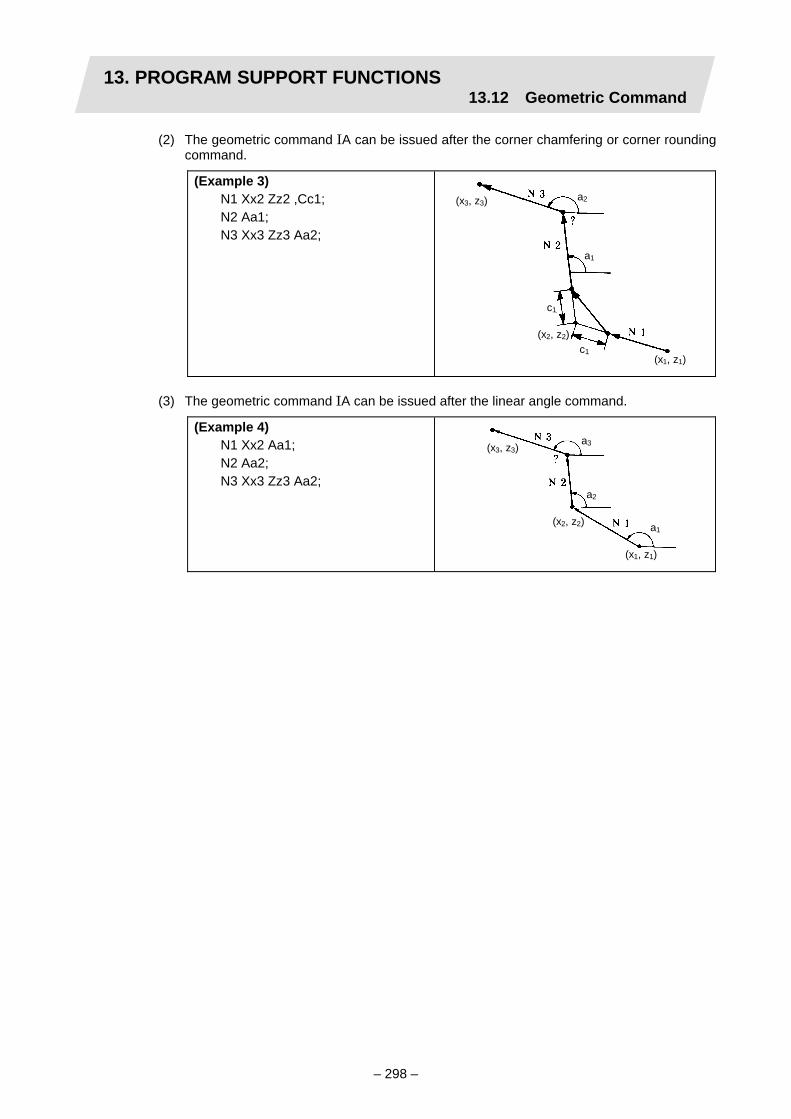
13. PROGRAM SUPPORT FUNCTIONS13.12 Geometric Command
– 298 –
(2) The geometric command IA can be issued after the corner chamfering or corner rounding command.
(Example 3) N1 Xx2 Zz2 ,Cc1; N2 Aa1; N3 Xx3 Zz3 Aa2;
c1
c1
a1
a2
(x1, z1)
(x2, z2)
(x3, z3)
(3) The geometric command IA can be issued after the linear angle command.
(Example 4) N1 Xx2 Aa1; N2 Aa2; N3 Xx3 Zz3 Aa2;
a1
a2
a3
(x1, z1)
(x2, z2)
(x3, z3)

13. PROGRAM SUPPORT FUNCTIONS13.13 Program Parameter Input
– 299 –
13.13 Program Parameter Input; G10/G11
Function and purpose
The parameters set from the setting display unit can be changed with the machining programs. Only the user parameters, machine parameters and PLC parameters can be changed.
Command format
The parameters are set with the following format in the data setting mode.
G10 L60; Parameter inputting command P major classification number N data number H bit type data ; P major classification number A axis number N data number
D byte type data ; P major classification number A axis number N data number
S word type data ; P major classification number A axis number N data number
L 2-word type data ; G11; Parameter inputting mode cancel (parameter inputting completed)
There are 8 types of data formats according to the type of parameter (axis-common and axis-independent) and data type, as listed below.
With axis-common data
Axis-common bit type parameter ・・・・・・・・・・P N H ; Axis-common byte type parameter ・・・・・・・・P N D ; Axis-common word type parameter・・・・・・・・P N S ; Axis-common 2-word type parameter ・・・・・・P N L ;
With axis-independent data
Axis-independent bit type parameter・・・・・・・P A N H ; Axis-independent byte type parameter ・・・・・P A N D ; Axis-independent word type parameter ・・・・P A N S ; Axis-independent 2-word type parameter・・・P A N L ;
(Note 1) The sequence of addresses in a block must be as shown above.
(Note 2) Designate the axis number of the system commanded with the G10 for the axis number designated with address A.

13. PROGRAM SUPPORT FUNCTIONS13.13 Program Parameter Input
– 300 –
[High-speed type parameter inputting command]
G10 L61; Parameter inputting command P major classification number A axis number N data number D byte type data ; P major classification number A axis number N data number S word type data ; P major classification number A axis number N data number L 2-word type data ; G11; Parameter inputting mode cancel (parameter inputting completed)
When the high-speed type parameter inputting command is used, the parameter input process can be completed faster than the normal parameter inputting command. The parameters that can be set with the high-speed parameter input command are limited to the axis specification parameters and servo parameters. There are three types of data section formats used according to the data type.
Axis-independent byte type parameter .............P2 A N D ; Axis-independent word type parameter ............P2 A N S ; Axis-independent 2-word type parameter .........P2 A N L ;
(Note 1) The sequence of addresses in a block must be as shown above.
(Note 2) The axis number designated with address A is the axis number calculated with the following formula.
[Designated axis number] = ([System number] -1) × 5 + [Axis number in system] (The basic definition number is used for the system number and axis number in system.)
(Note 3) The address N command value is valid only for value corresponding to the axis specification parameter and servo parameter. (Refer to "Appendix 6. Correspondence of program parameter input N numbers".)
Set the parameters in the data setting mode

13. PROGRAM SUPPORT FUNCTIONS13.13 Program Parameter Input
– 301 –
Detailed description
(1) Command address
The table below lists the addresses used in the data formats and their meanings.
Address Meaning Details of commands
P
Major classification number command address
This assigns the major classification number of the parameter data using a 2-digit number (positive integer) following P.
A Axis number command address
This enables independent data to be set for each control axis using an axis number following A when the input data are axis-independent data.
N Data number command address
This assigns the data numbers (inherent number for each data) for the parameter data using a 5-digit number (positive integer) following N. Refer to "Appendix 6" for the correspondences between the P numbers, N numbers and data contents.
H Bit type data command address
This is used for the data command in which both the byte size parameter and bit command can be assigned. The first digit in the 2-digit number (positive integer) following H assigns the command bit while the last digit assigns the parameter value (0 or 1). Example of application: Hd0: Sets bit "d" OFF. (d: 0 to 7) Hd1: Sets bit "d" ON. (d: 0 to 7)
D Byte type data command address
This assigns the byte type parameter value (decimal) with a number (integer) following D.
S Word type data command address
This assigns the word type parameter value (decimal) with a number (integer) following S.
L 2-word type data command address
This assigns the 2-word type parameter value (decimal) with a number (integer) following L.
(Note) Refer to the "Data types" in Appendix 6 for information on which addresses are used for the data command addresses.

13. PROGRAM SUPPORT FUNCTIONS13.13 Program Parameter Input
– 302 –
(2) Major classification number (P number) The correspondence of the major classification number and parameter data type is shown below.
Major classification
number (P number)
Type of parameter Axis data Remarks
1 System-common/ axis-common parameter
This user or machine parameter is common to each system or axis. The same parameter is changed from a machining program running in any system.
2 System-independent/ axis-independent parameter
This user or machine parameter is independent of each system or axis. The parameter designating each system from each system's machining program is changed.
3 Machine error compensation information
4 Machine error compensation amount
5 PLC constant 6 PLC timer 7 PLC counter 8 Bit selection parameter
13 System-independent/ axis-common parameter
This user or machine parameter is independent of each system and common to each axis. The parameter designating each system from each system's machining program is changed.
15 Communication parameter
16 Position switch parameter
This machine parameter is independent of each system and common to each axis. The parameter designating each system from each system's machining program is changed.
17 Spindle-type servo parameter The axis number is designated with an N
number. (P number for M500L compatibility)
20 Superimposition error compensation parameter
21 Spindle parameter (3) Data range
The general data range determined by each data type is shown below.
Data command address Data type Data range
H Bit
Bit0 Bit1 Bit2 Bit3 Bit4 Bit5 Bit6 Bit7OFF 00 10 20 30 40 50 60 70ON 01 11 21 31 41 51 61 71
D Byte –128 to +255 S Word –32768 to +65535 L 2-word –199999998 to 199999998
(Note) The data range in which each parameter value can be set differs according to each parameter. When creating the program, confirm the data range in Appendix 6 "Setting range (unit)", and input the correct value.

13. PROGRAM SUPPORT FUNCTIONS13.13 Program Parameter Input
– 303 –
(4) Parameter command unit The "unit" given in Appendix 6 refers to the minimum setting unit of the parameter data. Refer to the following table and command the correct data values for the "command unit", "interpolation unit" and "speed unit". For the metric/inch classification in the following table, follow the initial inch parameter state when setting the user parameters, and follow the constant inch input parameter state when setting the machine parameters. (a) Command unit
Linear axis Input unit type mm inch
Rotary axis
B 0.001mm 0.0001 inch 0.001° C 0.0001mm 0.00001 inch 0.0001°
(b) Interpolation unit
Linear axis Input unit type mm inch
Rotary axis
B 0.0005mm 0.00005 inch 0.0005° C 0.00005mm 0.000005 inch 0.00005°
(c) Speed unit
Linear axis Input unit type mm inch
Rotary axis
B 1.0mm/min 0.1 inch/min 1.0° C 0.1mm/min 0.01 inch/min 0.1°
(5) Examples of data formats
(a) Axis-common parameters
Format used Data type N number setting P1 N H ; P1 N D ; P1 N S ; P1 N L ;
Bit Byte Word
2-word
(Refer to "Appendix 6" for details)
(Example) Setting the 2nd miscellaneous function code (#1109 M2name) to "B". P13 N40 D66; (The "B" ASCII code is 0x42 [hexadecimal] →
66 [decimal])
(b) Axis-independent parameters
Format used Data type A number setting N number setting
P2 A N H ; P2 A N D ; P2 A N S ; P2 A N L ;
Bit Byte Word
2-word
1 to No. of control axes
(Refer to "Appendix 6" for details)
(Example) Setting the X-axis rapid traverse rate (#2001 rapid) to 15000. P2 A1 N8 L15000;

13. PROGRAM SUPPORT FUNCTIONS13.13 Program Parameter Input
– 304 –
(c) Machine error compensation information (Machine error compensation parameter)
Format used Data type A number setting N number setting
P3 A N S ; P3 A N L ;
Word 2-word 1 to 12
(Refer to "Appendix 6" for details)
(Example 1) The second set of the machine error compensation sets the 2nd axis of system 1 in the basic axis (#4001 cmpax).
P3 A2 N1 S256; (System 1 - 2nd axis is 0x0100 [hexadecimal] → 256 [decimal])
(Example 2) The first set of the machine error compensation sets 10000 in the division pitch (#4007 spcdv).
P3 A1 N7 L20000; (Setting interpolation unit)
(d) Machine error compensation amount (Machine error compensation parameter)
Format used Data type N number setting P4 N D ; Byte 1 to 128 × No. of control axes
(Example) Set –4 for the compensation data #4305. P4 N5 D–4;
(e) PLC constant
Format used Data type N number setting P5 N L ; 2-word 1 to 48
(Example) Set 100 for the PLC constant #6308. P5 N8 L100;
(f) PLC timer
Format used Data type N number setting P6 N S ; Word 0 to 103
(Example) Set 100 for the PLC timer #6017. P6 N17 S100;
(g) PLC counter
Format used Data type N number setting P7 N S ; Word 0 to 23
(Example) Set 20 for the PLC counter #6203. P7 N3 S20;
(h) Bit selection parameter
Format used Data type N number setting P8 N H ; P8 N D ;
Bit Byte
1 to 96 (contents fixed for 45 to 95) (Refer to "Appendix 6" for details.)
(Example 1) Set the #6401 bit pattern to 01010101. P8 N1 D85; (01010101 [binary] → 85 [decimal])
(Example 2) Turn #6406 bit 3 ON (set to 1). P8 N6 H31;

13. PROGRAM SUPPORT FUNCTIONS13.13 Program Parameter Input
– 305 –
Example of program
(Example 1) Setting the G71 minimum cut to 1mm
: G10 L60; P13 N320 L2000; G71 minimum cut (1mm/0.5µm = 2000)
[interpolation unit] G11; :
(Example 2) Decimal point command type 1/2 setting
: G10 L60; P1 N912 H51; Setting to decimal point type 2 G11; : G00 X-100 Z-200; Equivalent to X-100. Z-200. : G10 L60; P1 N912 H50; Setting to decimal point type 1 G11; : G00 X-100 Z-200; Equivalent to X-0.1. Z-0.2 :
(Example 3) Making the soft limit invalid
: G10 L60; P2 A1 N641 H21; X-axis soft limit invalid P2 A2 N641 H21; Z-axis soft limit invalid G11; :
(Example 4) Setting the X-axis rapid traverse rate to 24000mm/min
: G10 L60; P2 A1 N8 L24000; X-axis rapid traverse rate G11; :

13. PROGRAM SUPPORT FUNCTIONS13.13 Program Parameter Input
– 306 –
Precautions and restrictions
(1) The parameter inputting function option is required in order to use this function. Program
error "P420" results when it is commanded without the option. (2) Program error "P421" results in an illegal parameter number (major classification number,
axis number or data number). The same error occurs when the setting data (bit type, byte type, word type or 2-word type data) have exceeded the data range.
(3) Program error "P421" results if in the parameter inputting format the major classification number, data number and setting data for axis-common data or the major classification number, axis number, data number and setting data for axis-independent data are not commanded.
(4) Program error "P421" results when any G command except G11 and any address except P, A, N, H, D, S and L are commanded in the parameter inputting mode.
(5) Program error "P421" results when a parameter inputting command is issued during a fixed cycle modal or nose R compensation modal.
(6) Command the axis number for the axis-independent parameter input in the basic definition axis row. Note that even if the axis layout changes with the cross machining command or random axis exchange command, the parameter will be input in the basic definition axis row.
(7) If two or more setting data items with different types are commanded in the same block, the program error "P421" will occur.
(8) When a program error has occurred in the parameter inputting mode, first remedy the error and then proceed again with the parameter inputting.
(9) If the same address is commanded two or more addresses in the same block, the latter command will be valid.
(10) It is not possible to use the binary type data command address "B" with the parameter inputting. Use the byte type data command address "D" instead.
(11) Always command G11; (parameter input mode cancel) at the end of the data setting. (12) Note that the parameter input data format differs from the parameter tape. (13) Only the user parameters, machine parameters and PLC parameters can be set with
program parameter input. (14) Some parameters are not validated immediately when input, and the power must be
turned OFF/ON to validate them. (Refer to the Parameter Manual.) (15) If a value other than the axis specification parameter or servo parameter value is issued
for the major classification or classification number (P, N address command value) when the high-speed type parameter input command (G10L61) is commanded, that command will be invalid.
(16) Up to 20 parameters can be commanded at once with the high-speed type parameter input command (G10L61).
G10 L61 P2 ・・・・・・・ ; : : G10 L61 P2 ・・・・・・・・ ; G11 ;
If more than 20 parameters are commanded, a program error (P421) will occur. (17) Compatibility with older model (M500L)
(a) The parameters changed with the parameter input command will not return to the original setting when the power is turned OFF/ON. (The parameters that returned to the original setting when the M500L power was turned OFF/ON will not return to the original setting with the M600L.)
(b) If a designation differing from "Appendix 6" is made, the set data may differ.
Up to 20 parameters can be commanded.

13. PROGRAM SUPPORT FUNCTIONS13.14 Programmable In-position Check
– 307 –
13.14 Programmable In-position Check
Function and purpose
This function allows the in-position width (position error amount), a condition for shifting from the execution block to the next block's process, to be commanded from the machining program with the positioning (rapid traverse: G0) command block and with the linear interpolation (G01) and circular interpolation (G02/G03) commands. In blocks that do not interfere with the workpiece, the machining time can be shortened by commanding the in-position width.
X axis positioning
Z axis positioning
ServoCommand
In-position width(position error amount)
Next block
Block in execution
G0 Z ;G0 X ,I5.0;
Command format
The in-position width is designated with the " ,I" command in the block to validate this function.
(1) Positioning command (G00)
G00 X Z ,Iinpos;
(2) Linear interpolation (G01)/circular interpolation (G02/G03) command
G01 X Z F ,Iinpos; G02(G03) X Z R F ,Iinpos;
The ",I" command is valid only in the following cases in which deceleration check is carried out.
(a) When the error detect switch is ON.
(b) When G09 (exact stop check) is commanded in the same block.
(c) When G61 (exact stop check mode) is selected.
(d) When the next block is G00.

13. PROGRAM SUPPORT FUNCTIONS13.14 Programmable In-position Check
– 308 –
(3) Cycle command
G83 X Z R Q P F ,Iinpos;
This function is valid between the G0 and G0 block in the cycle when commanded in a cycle such as the hole drilling fixed cycle, turning fixed cycle or compound type turning cycle.
(4) Command address
,Iinpos inpos
In-position width (inpos) designation Command unit : mm/inch, decimal point command valid Command range : For minimum command unit 0.001mm/0.0001inch
0 to 999.999mm or 0 to 99.9999inch
If a command exceeding the command range is issued, a program alarm (Setting value range over) will occur. In addition to numeric values, variables and macro operation expressions can be set for the inpos value.
(Example) ,I [#100] ,I [#101∗1.2] ,I [2.3/SIN [60]]
(Note) This function is invalid if the ",I" command is commanded in an independent block or if it is commanded in a block not containing the above valid commands.
Detailed description
(1) When the position error amount of the block being executed is less than the in-position
width designated with this command, execution of the next block will start.
(2) The in-position width for this command is valid only in the command block, so blocks that do not have the in-position width command will use the deceleration check method.
(3) If there are multiple moving axes, the system will check whether the combined position error amount of each of the moving axes is less than the in-position width for this command, and then will start execution of the next block.
Position error amount < in-position width(Position error amount)
Next block
G0 Z ;G0 X ,I5.0;
Check start of next block'sstart timing
Start of next block
X axis positioning
Z axis positioning
Servo
Command
Command
Block in execution
Position error amount = (end point machine position – feedback machine position)

13. PROGRAM SUPPORT FUNCTIONS13.14 Programmable In-position Check
– 309 –
Example of program
Metric command mode, error detect OFF
: G00 X100. Z100. ,I5.0; Execute in-position width at 5mm G00 X30.; Execute deceleration check method with parameters G01 Z-30. F10. ,I1.0; In-position width command value is invalid as the
G01-G01 commands continue (an error does not occur)G01 X50. Z-50. ,I2.0; As deceleration check is valid with G01-G00 command,
execute in-position width at 2mm G00 X80. ,I [#100]; Execute in-position width with variable #100 value : : G09 X20. Z-40. ,I3.0; G09 is commanded and deceleration check is valid, so
execute in-position width at 3mm : : G83 Z-50. R5. Q4. F20. ,I0.5; Execute G0-G0 block in cycle with in-position width
0.5mm
Precautions
(1) The in-position width command value and the position error amount are compared at a set
time. Thus, the timing for starting the next block may be slightly delayed from the set parameter value.
(2) In a fine segment block with a fast feedrate, the timing for starting the next block may be delayed.
(3) When the calculation request (Y233) is input with the PLC signal, the timing for starting the next block may be delayed.
(4) This function is invalid for axes in the automatic machine lock state.
(5) When this function is used for axes having an acceleration/deceleration pattern combination (example: rapid traverse linear acceleration/deceleration + rapid traverse primary delay acceleration/deceleration), an error will occur in the in-position width.
(6) At sections where the axis movement direction is reversed, this function will be invalidated to prevent a load from being applied on the motor.
Relation with other functions
(1) At the instant the superimposition synchronization command (G125, G126) or synchronization
command during axis movement (G128) is executed with another system, in movement blocks that have systems with axes related to these functions, the timing for starting the next block may be delayed.
(2) If the next block reads in the position information with the coordinate system setting command (G92), machine coordinate system selection command (G53) or variable, the timing for starting the next block may be delayed.
(3) The I command is invalid during the milling machining mode. (An error will not occur.)

13. PROGRAM SUPPORT FUNCTIONS 13.15 Positioning (G00)/Machine Coordinate System Selection (G53) Feedrate Designation
– 310 –
13.15 Positioning (G00)/Machine Coordinate System Selection (G53) Feedrate Designation
Function and purpose
The axis feedrate can be designated for when G00 (positioning command) or G53 (machine coordinate system selection) is designated.
Command format
The feedrate for moving is commanded with a ",F" command. This rate is used to move in the G00 block, G00 mode, G53 movement block, to the initial point of the hole position in the hole drilling fixed cycle block, and to move to the initial point of the hole position in the block during the hole drilling fixed cycle.
<Designation of feedrate for G00 block>
G00 X_ Z_ ,F1000 ;
<Designation of feedrate for movement command in G00 mode>
G00 ; X_ Z_ ,F1000 ;
<Designation of feedrate for G53 block>
G53 X_ Z_ ,F1000 ;
<Designation of feedrate for command to move to initial point of hole position in hole drilling cycle>
G8x X_ ………. ,F1000 ; X_ ………. ,F500 ; : G80 ; :
G83: Deep hole drilling cycle (face) G84: Tapping cycle (face) G85: Boring cycle (face)
G8x Z_ ………. ,F1000 ; Z_ ………. ,F500 ; : G80 ; :
G87: Deep hole drilling cycle (longitudinal) G88: Tapping cycle (longitudinal) G89: Boring cycle (longitudinal)

13. PROGRAM SUPPORT FUNCTIONS 13.15 Positioning (G00)/Machine Coordinate System Selection (G53) Feedrate Designation
– 311 –
Detailed description
(1) The ",F" command is valid only in the commanded block.
(2) If the ",F" command is issued in a block other than the G00, G00 mode, G53 or the movement block to the initial point of the hole position in the hole drilling cycle, ",F" will be ignored.
(3) Command range Input command
unit (CS) mm/inch Command range Handling of decimal point
mm system 0.001 to 480000.000 (mm/min) 1 (=1.000) 1. (=1.000) B inch system 0.0001 to 18897.6378 (inch/min) 1 (=1.0000) 1. (=1.0000) mm system 0.0001 to 108000.0000 (mm/min) 1 (=1.0000) 1. (=1.0000) C inch system 0.00001 to 4251.96850 (inch/min) 1 (=1.00000) 1. (=1.00000)
If the command range is exceeded, a program error (P35) will occur. (This also applies when a negative value is applied.) Even if the ",F" command is commanded in a block other than the G00, G00 mode, G53 or the movement block to the initial point of the hole position in the hole drilling cycle, if the command range is exceeded a program error (P35) will occur.
(4) The handling of the ",F" command differs according to the state of the control parameter "#8113 G0 non-interpolation".
Control parameter "#8113 G0 non-interpolation" Handling of ",F" command
OFF Handled as the interpolation speed ON Handled as the commanded speed for each axis.
Feedrate for G00 X200. Z300. ,F1000 command
X
Z
200
300fz = 832.05 (mm/min)
fx =
554
.70
(mm
/min
)
fx =
100
0 (m
m/m
in)
X
Z
200
300fz = 1000 (mm/min)
1000 (mm/min)
Start point Start point
<When "G0 non-interpolation" is OFF>
End point
<When "G0 non-interpolation" is ON>
End point
fx: X axis effective speed fz: Z axis effective speed fx: X axis effective speed fz: Z axis effective speed
(5) If ",F" is not commanded, the rapid traverse rate (Note 1) set with the axis specifications parameter will be valid.

13. PROGRAM SUPPORT FUNCTIONS 13.15 Positioning (G00)/Machine Coordinate System Selection (G53) Feedrate Designation
– 312 –
(6) The ",F" command speed is clamped by the rapid traverse rate (Note 1) set with the axis specifications parameter. The speed clamp method differs according to the state of control parameter "#8113 G0 non-interpolation".
#8113 G0 non-interpolation Speed clamp
ON
When the commanded ",F" (interpolation speed) is converted into a per axis speed, if there is any axis that exceeds the rapid traverse rate (Note 1) parameter, the interpolation speed will be calculated so that the rapid traverse rate is not exceeded.
OFF
Any axis with a commanded ",F" (per axis speed) exceeding the rapid traverse rate (Note 1) parameter will be clamped by the parameter speed. (An axis that does not exceed the rapid traverse rate parameter will move at the commanded speed.)
(Note 1) Normally, the axis specification parameter's rapid traverse rate (#2001 rapid) is selected for the rapid traverse rate parameter. However, when using the random superimposition control/NC axis superimposition control related axis, one of the following is selected according to the superimposition related axis movement direction and movement mode: rapid traverse rate (#2001 rapid), 2-axis superimposition rapid traverse rate 0 (#2021 plrap0), 2-axis superimposition rapid traverse rate 1 (#2022 plrap1), 3-axis superimposition rapid traverse rate 0 (#2037 pl3rap0), 3-axis superimposition rapid traverse rate 1 (#2038 pl3rap1) or 3-axis superimposition rapid traverse rate 2 (#2039 pl3rap2).

13. PROGRAM SUPPORT FUNCTIONS 13.15 Positioning (G00)/Machine Coordinate System Selection (G53) Feedrate Designation
– 313 –
Example of program
(1) Feedrate command during G00 block, or G00 mode (For G00 interpolation)
: G00 X100. Z100. ,F1000; Moves at the XZ composite speed 1000 (mm/min). X200. Z200.; Interpolates at the maximum feedrate that does not exceed
the rapid traverse rate parameter set for each X and Z axis. X300. Z300. ,F2500; Moves at the XZ composite speed 2500 (mm/min). :
(2) Feedrate command during G53 mode
: G53 X100. Z100. ,F3000; Moves at the XZ composite speed 3000 (mm/min). :
(3) Movement speed command to initial point of hole position in hole drilling cycle (For
longitudinal tapping cycle) : G88 X-20. Z30 R5. F1.D3 S500 ,R1 ,F2000;
Moves to the hole position's initial point (Z30.) at 2000(mm/min). (Moves at the X axis rapid traverse rate (parameter setting value) from the hole position's initial point to the R point, and from the R point to the hole position's initial point after tap cutting is completed.)
X-20. Z35. R5.; Moves with the Z axis rapid traverser rate (parameter setting value) to the hole position's initial point (Z35.).
X-20. Z40. R5. ,F3000; Moves to the hole position's initial point (Z40.) at 3000(mm/min). (Moves at the X axis rapid traverse rate (parameter setting value) from the hole position's initial point to the R point, and from the R point to the hole position's initial point after tap cutting is completed.)
G80; :

13. PROGRAM SUPPORT FUNCTIONS 13.15 Positioning (G00)/Machine Coordinate System Selection (G53) Feedrate Designation
– 314 –
Relation with other functions
(1) Rapid traverse constant inclination control
When ",F" is commanded, constant inclination control is carried out in respect to the speed commanded with ",F".
・
Ts
・
Ts
↑
↑
→
→
When ",F" is not commanded
Speed
Rapid t raverserate set inparameters
Operation when rapid traverseconstant incl ination is valid
Operation when rapid traverseconstant inclination is invalid
Time
When ",F" is commanded
Speedcommandedwith " ,F"
Ts: Time constant
Speed
Time
Operation when rapid traverseconstant incl ination is valid
Operation when rapid traverseconstant inclination is invalid
(2) Rapid traverse override This is the override for the ",F" command.
(3) Override cancel Override cancel is invalid in respect to the rapid traverse override even when ",F" is commanded. If manual override is validated when dry run is selected, override cancel will be valid for the cutting override.
(4) Dry run Dry run is valid when control parameter (#8101 G0 dry run) is ON, and rapid traverse is OFF. The axis will move at the set manual feedrate. Cutting feed override is also valid when manual override valid is turned ON.
(5) External deceleration This is valid even when ",F" is commanded.
(6) Milling The ",F" command is valid also during the milling mode.
(7) Program check The movement speed during the program check of the block with valid ",F" command is calculated from the ",F" command and program check speed.
(8) High-speed simple program check The time is calculated based on the ",F" command.

13. PROGRAM SUPPORT FUNCTIONS 13.15 Positioning (G00)/Machine Coordinate System Selection (G53) Feedrate Designation
– 315 –
(9) Control axis superimposition (G126) The ",F" command is clamped according to the rapid traverse rate parameter selected by the superimposition related axis movement direction and movement mode. These parameters include: 2-axis superimposition rapid traverse rate 0 (#2021 plrap0), 2-axis superimposition rapid traverse rate 1 (#2022 plrap1), 3-axis superimposition rapid traverse rate 0 (#2037 pl3rap0), 3-axis superimposition rapid traverse rate 1 (#2038 pl3rap1) and 3-axis superimposition rapid traverse rate 2 (#2039 pl3rap2).
(10) Programmable in-position check This is valid even when ",F" is commanded.
Precautions
(1) If ",F" is commanded when the G00/G53 feedrate command option is not available, a
program error (P39) will occur.
(2) The ",F" command is valid only in the commanded block.
(3) The ",F" command and "F" command can be commanded in the same block. The "F" command will be the feedrate for cutting feed in this case.
(4) ",F" will be ignored if commanded in a block other than the G00, G53, G00 mode, or movement block to initial point of hole position in hole drilling cycle, or in a block that does not have a movement command (axis address command).
(5) When the tool compensation operation parameter (basic common parameter #1317 Tmove) is set to 0 (compensate even blocks without a movement command), if ",F" is commanded for a tool compensation command (T command) block that has no movement command, the compensation movement will take place at the commanded speed only in the G00 mode.
(6) If ",F" is commanded in a nose R cancel command (G40) block that has not movement, the nose R cancel operation will take place at the commanded speed only in the G00 mode.
(7) If the ",F" command exceeds the command range, a program error (P35) will occur. (a) A program error (P35) will also occur if a negative value is commanded. (b) Even if the ",F" command is issued in a block other than G00, G53, G00 mode, or
movement block to initial point of hole position in hole drilling cycle, a program error (P35) will occur if the command range is exceeded.

13. PROGRAM SUPPORT FUNCTIONS 13.16 Inclined Coordinate Rotation; G173
– 316 –
13.16 Inclined Coordinate Rotation; G173
Function and purpose
The inclined coordinate rotation command allows the coordinate system for the IK plane, which configures the coordinate system, to be rotated by the designated angle using the J axis as the rotation center axis (or it allows the coordinate system for the JK plane to be rotated by the designated angle using the I axis as the rotation center axis). When machining a complicated shape having a position rotated from the program coordinate system, the original machining shape program is created with a non-rotating coordinate system. Then, using the inclined coordinate rotation command to designate the rotation angle, a random machining shape can be programmed easily. The coordinate system that rotates each coordinate system (workpiece coordinate system, local coordinate system) at the point where the inclined coordinate rotation command is issued is configured.
+X
θ
+Xp
+Z
+Zp
Xp-Zp coordinates: Rotation plane coordinates (program plane)X-Z coordinates : Orthogonal plane coordinates (plane before rotation)
When coordinates are rotated by angle - θ
Cutting surface Rotation planecoordinatesWorkpiece center
Rotation center
Workpiece center
(G173 X_Z_D-θ)
Examples of inclined coordinate rotation command and movements
Z
X
Z
XZ
X
G173 X_Z_ D0. G173 X_Z_ D-60. G173 X_Z_ D-90.
Z
X
Z
X
Z
X
G173 X_Z_ D0. G173 X_Z_ D30. G173 X_Z_ D90.

13. PROGRAM SUPPORT FUNCTIONS 13.16 Inclined Coordinate Rotation; G173
– 317 –
Command format
G173 Xx Zz Dd ; Inclined coordinate rotation ON (Rotate IK plane centering on J axis)
G173 Yy Zz Dd ; Inclined coordinate rotation ON (Rotate JK plane centering on I axis)
Xx/Yy/Zz : Rotation center coordinates
Dd : Rotation angle
G173; or G173 X0 Z0 D0; Inclined coordinate rotation cancel G173; or G173 Y0 Z0 D0; Inclined coordinate rotation cancel
Address Meaning of address Command range (unit) Remarks
X/Y/Z Rotation center coordinates
Command mode
Input unit system
Internal input unit
Command range
Metric 0.001 (mm)
0.00001 (inch)
-99999.999 to 99999.999
0.0001 (mm)
-9999.999 to 9999.999
0.0001 (mm)
0.001 (mm)
-9999.9999 to 9999.9999
0.0001 (mm)
-9999.9999 to 9999.9999
Inch 0001 (inch)
0.0001 (inch)
-9999.9999 to 9999.9999
0.00001 (inch)
-999.9999 to 999.9999
00001 (inch)
0.0001 (inch)
-999.99999 to 999.99999
0.00001 (inch)
-999.99999 to 999.99999
• The position from the local coordinate zero point on the orthogonal plane is commanded with an absolute value.
• The rotation center coordinate cannot be omitted.
D Rotation angle Input unit system Internal
input unitCommand
range 0.001 (°) 0.001 (°) -359.999
to 359.999 0.0001(°) -359.999
to 359.999 0.0001 (°) 0.001(°) -359.9999
to 359.9999 0.0001(°) -359.9999
to 359.9999
• Looking from the rotation center, the direction to rotate in the Z axis (+) direction is set as the rotation angle (+) direction by using the X axis (+) direction (or Y axis (+) direction) as 0°.
• Rotation angle (D) is a modal, and will not change until a new angle is commanded.
• The rotation angle (D) can be omitted. If omitted when the initial G173 is commanded, D will be set to 0. If G173 is commanded during the inclined coordinate rotation mode, this will be a modal D command.
• Rotation angle (D) is an absolute value command regardless of the G90/G91 command.

13. PROGRAM SUPPORT FUNCTIONS 13.16 Inclined Coordinate Rotation; G173
– 318 –
* The relation of the polarity and rotation angle command direction in the basic machine coordinate system for the axis targeted for inclined coordinate rotation is shown below.
+Y
+ +Z
+Y
+Z +
+Y
+Z+
+Y
+Z +
+X
++Z
+X
+Z+
+X
+Z+
+X
+Z+
Rotation angelcommanddirection
<When rotating IK plane centering on J axis>
<When rotating JK plane centering on I axis>
Rotation angelcommanddirection
Rotation angelcommanddirection
Rotation angelcommanddirection
Rotation angelcommanddirection
Rotation angelcommanddirection
Rotation angelcommanddirection
Rotation angelcommanddirection
Feedrate
The parameter setting value for the actual axis is used as the feedrate for the axis targeted for inclined coordinate rotation. During the inclined coordinate rotation mode, the rapid traverse rate and cutting feed clamp speed are obtained considering the rotation angle from the basic machine coordinate system. (Example) Clamp speed for cutting feed (G01) in inclined coordinate rotation mode (IK plane)
+
+
-
-
+
+-
-
●:
○:
I axis feed directionon basic machine coordinatesystem (actual axis)
I axis feed directionon rotation coordinatesystem
Coordinate rotationRotation angle
Clamp speed
Command composite movementdirection on rotation coordinates
I axis clamp speed (parameter setting value)on basic machine coordinate system (actual axis)
K axis feed directionon basic machinecoordinate system(actual axis)
K axis feed directionon rotation coordinate system
K axis clamp speed (parameter setting value)on basic machine coordinate system (actual axis)

13. PROGRAM SUPPORT FUNCTIONS 13.16 Inclined Coordinate Rotation; G173
– 319 –
Input setting unit
When using the inclined coordinate rotation control, set the parameters with an internal input unit. The relation of the input unit system and the internal input unit system parameter settings is shown below.
Parameter
No. #1005 iout
#8117 Initial inch
Input unit
#1362sunit
Machining program
command
Internal input unit
Command output
minimum unit
1 OFF (Metric output)
OFF (Metric command)
0.001 (mm)
0 0.001 (mm)
0.001 (mm)
0.001 (mm)
2 1 0.001 (mm)
0.0001 (mm)
0.0001 (mm)
3 0.0001 (mm)
0 0.0001 (mm)
0.001 (mm)
0.0001 (mm)
4 1 0.0001 (mm)
0.0001 (mm)
0.0001 (mm)
5 ON (Inch command)
0.0001 (inch)
0 0.0001 (inch)
0.0001 (inch)
0.001 (mm)
6 1 0.0001 (inch)
0.00001 (inch)
0.0001 (mm)
7 0.00001 (inch)
0 0.00001 (inch)
0.0001 (inch)
0.0001 (mm)
8 1 0.00001 (inch)
0.00001 (inch)
0.0001 (mm)
9 ON (Inch output)
OFF (Metric command)
0.001 (mm)
0 0.001 (mm)
0.001 (mm)
0.0001 (inch)
10 1 0.001 (mm)
0.0001 (mm)
0.00001 (inch)
11 0.0001 (mm)
0 0.0001 (mm)
0.001 (mm)
0.00001 (inch)
12 1 0.0001 (mm)
0.0001 (mm)
0.00001 (inch)
13 ON (Inch command)
0.0001 (inch)
0 0.0001 (inch)
0.0001 (inch)
0.0001 (inch)
14 1 0.0001 (inch)
0.00001 (inch)
0.00001 (inch)
15 0.00001 (inch)
0 0.00001 (inch)
0.0001 (inch)
0.00001 (inch)
16 1 0.00001 (inch)
0.00001 (inch)
0.00001 (inch)

13. PROGRAM SUPPORT FUNCTIONS 13.16 Inclined Coordinate Rotation; G173
– 320 –
Relation with other functions
Function name Operation Remarks Positioning (G00) This will function even during the inclined
coordinate rotation mode. Note that even when G00 non-interpolation is selected, positioning including the axis targeted for inclined coordinate rotation in the inclined coordinate rotation mode will be positioned with interpolation.
The feedrate will be controlled with the rotation coordinates so that the rapid traverse rate (parameter setting) set for the actual axis is not exceeded.
Linear interpolation (G01) Circular interpolation (G02/G03) Helical interpolation
These will function even during the inclined coordinate rotation mode.
The feedrate will be controlled with the rotation coordinates so that the cutting clamp speed (parameter setting) set for the actual axis is not exceeded.
Milling interpolation (G12.1/G13.1)
The program error (P711) will occur if inclined coordinate rotation is commanded during the G12.1 mode. The program error (P712) will occur if G12.1 is commanded during the inclined coordinate rotation mode.
Override The override will be applied in respect to the speed on the rotation coordinate system during the inclined coordinate rotation mode.
Automatic acceleration/deceleration after interpolation
This will function even during the inclined coordinate rotation mode.
Constant inclination acceleration/deceleration
This will function even during the inclined coordinate rotation mode.
Set the time constants (parameter settings) for the axes targeted for the set rotation coordinates to the same value.
Thread cutting The program error (P711) will occur if inclined coordinate rotation is commanded during the thread cutting modal. The program error (P712) will occur if thread cutting is commanded during the inclined coordinate rotation mode.
Manual mode (Jog, incremental, handle)
This will function even during the inclined coordinate rotation mode. The axis selection will be valid for the axes on the rotation coordinate system. Note that if the following occurs during the inclined coordinate rotation mode, the "M01 Operation error 1121" will occur: If a feed axis is selected for the inclined coordinate rotation two target axes, the "M01 Operation error 1121" will occur. (If the above operation is carried out while axis 1 is moving, both axes will stop.)
The error can be reset with the reset signal input after one or both axes selection signals for the axis targeted for inclined coordinate rotation (axis selection valid signal for handle) is turned OFF.
Manual mode (manual random feed)
During the inclined coordinate rotation mode, if a command is issued to the axis targeted for inclined coordinate rotation, the "M01 Operation error 1121" will occur.
The error can be reset with the reset signal input.
Constant surface speed control
This will function even during the inclined coordinate rotation mode.
The surface speed is calculated with the coordinate system on the rotation coordinates.
Tool length, wear compensation
These will function even during the inclined coordinate rotation mode. Whether to hold the compensation amount at reset is determined by the parameter settings.
The tool compensation amount with the inclined coordinate rotation command is not canceled. Command the tool compensation to match the tool being used on the rotation coordinates.

13. PROGRAM SUPPORT FUNCTIONS 13.16 Inclined Coordinate Rotation; G173
– 321 –
Function name Operation Remarks
Nose R compensation This will function even during the inclined coordinate rotation mode. The compensation amount will be canceled at reset. If the inclined coordinate rotation command is issued during the nose R compensation mode, the program error (P711) will occur.
Machine coordinate system setting (G53)
This will function even during the inclined coordinate rotation mode. The axis will move to the machine coordinate position on the rotation coordinate system.
Coordinate system setting (G92)
This will function even during the inclined coordinate rotation mode.
Workpiece coordinate system selection (G54 to G59)
This will function even during the inclined coordinate rotation mode.
Local coordinate system setting (G52)
This will function even during the inclined coordinate rotation mode.
External workpiece coordinate system offset
This will function even during the inclined coordinate rotation mode.
Plane selection The plane will change to the G17 plane when inclined coordinate rotation is commanded. This will function even during the inclined coordinate rotation mode. (Other planes can be changed to.)
The state before inclined coordinate rotation will be held even after the rotation coordinate system is changed.
Manual reference point return
During the inclined coordinate rotation mode, if this is commanded to an axis targeted for inclined coordinate rotation, the "M01 Operation error 1121" will occur.
The error can be reset with the reset signal input after the axis selection signal for the axis targeted for inclined coordinate rotation is turned OFF.
Automatic reference point return (G28/G29) 2nd, 3rd, 4th reference point return (G30) Reference point check (G27)
During the inclined coordinate rotation mode, if these are commanded to an axis targeted for inclined coordinate rotation, the program error (P712) will occur.
Absolute position detection (dog-type)
During the inclined coordinate rotation mode, if this is commanded to an axis targeted for inclined coordinate rotation, the "M01 Operation error 1121" will occur.
The error can be reset with the reset signal input after the axis selection signal for the axis targeted for inclined coordinate rotation is turned OFF.
Absolute position detection (dogless-type)
During the inclined coordinate rotation mode, an error will occur if the absolute position setting operation is attempted to an axis targeted for inclined coordinate rotation. <Error>
When data is set in "Abs pos set #1201" from setting screen: Setting not possible When data is set in "Abs pos set #1201" from DDB: DDB error will turn ON
Absolute position detection (automatic dogless)
During the inclined coordinate rotation mode, if this is commanded to an axis targeted for inclined coordinate rotation, the "M01 Operation error 1121" will occur.
The error can be reset with the reset signal input after the axis selection signal for the axis targeted for inclined coordinate rotation is turned OFF.
Tool position return During the inclined coordinate rotation mode, if this is commanded to an axis targeted for inclined coordinate rotation, the program error (P712) will occur.

13. PROGRAM SUPPORT FUNCTIONS 13.16 Inclined Coordinate Rotation; G173
– 322 –
Function name Operation Remarks
Automatic machine lock During the inclined coordinate rotation mode, the automatic machine lock signal for two axes targeted for inclined coordinate rotation is valid when the signal is selected for two axes comprising a set. During the inclined coordinate rotation mode, if the automatic machine lock signal is selected for only one of two axes targeted for inclined coordinate rotation, the error "M01 Operation error 1121" will occur when the machining program block is started. If the automatic machine lock signal is selected for only one of the two axes targeted for inclined coordinate rotation during a block in the inclined coordinate rotation mode, an error will occur when the block ends.
The error can be reset by turning the automatic machine lock signal ON or OFF for both axes targeted for the inclined coordinate rotation set.
In the inclined coordinate rotation canceled state, if a hypothetical coordinate setting command is issued when automatic machine lock signal is selected for only one of the two axes targeted for inclined coordinate rotation, the error "M01 Operation error 1120" will occur.
The error can be reset with the reset signal input.
Manual machine lock During the inclined coordinate rotation mode, the manual machine lock signal for two axes targeted for inclined coordinate rotation is valid when the signal is selected for two axes comprising a set. If the manual machine lock signal is selected for one of the two axes targeted for inclined coordinate rotation during the inclined coordinate rotation mode and manual operation mode, the error "M01 Operation error 1121" will occur. During the inclined coordinate rotation mode, if any of the axes in the inclined coordinate rotation setting system is moving with the manual mode, and the manual machine lock signal is selected for only one of the two axes targeted for inclined coordinate rotation, all axes in the system will stop and an error will occur.
The error can be reset by turning the manual machine lock signal ON or OFF for both axes targeted for inclined coordinate rotation.
If the hypothetical coordinate setting command is issued with the DDBS while inclined coordinate rotation is canceled and the manual machine lock signal is selected for only one of the two axes targeted for inclined coordinate rotation, the error "M01 Operation error 1120" will occur.
The error can be reset with the reset signal input.
Program check operation Reverse run extending over the inclined coordinate rotation command/cancel command is not possible.Reverse run of the inclined coordinate rotation command/cancel command is prohibited.
NC reset The inclined coordinate rotation mode is canceled by resetting.
Automatic handle interrupt Manual/automatic simultaneous
During the inclined coordinate rotation mode, if a command is issued to an axis targeted for inclined coordinate rotation, the "M01 Operation error 1121" will occur.
The error can be reset with the reset signal input.
Manual ABS This will function even during the inclined coordinate rotation mode. Note that if the inclined coordinate rotation command/cancel command is issued when manual ABS is OFF, the manually moved amount will be added to the position after coordinate conversion. (Same as manual ABS ON state.)
Hole drilling fixed cycle Synchronous tapping cycle (G84/G88) Turning fixed cycle
This will function even during the inclined coordinate rotation mode. If inclined coordinate rotation command/cancel command is issued during the fixed cycle mode, the program error (P34) will occur.

13. PROGRAM SUPPORT FUNCTIONS 13.16 Inclined Coordinate Rotation; G173
– 323 –
Function name Operation Remarks
Compound lathe cutting fixed cycle
If the compound lathe cutting fixed cycle is commanded during the inclined coordinate rotation mode, the program error (P712) will occur. If inclined coordinate rotation command is issued during the fixed cycle mode, the program error (P34) will occur.
Mirror image This will function even during the inclined coordinate rotation mode. The mirror image will be applied on the axis on the rotation coordinates. If inclined coordinate rotation is commanded during mirror image, the program error (P711) will occur.
Double-turret mirror image T command double-turret mirror image
If these are commanded during the inclined coordinate rotation mode, the program error (P712) will occur. If inclined coordinate rotation is commanded during mirror image, the program error (P711) will occur.
Position information retrieving variables
Previous block end point coordinates (#5001 to)
Machine coordinates (#5021 to)
The status of the rotation coordinate system is read during the inclined coordinate rotation mode.
Workpiece coordinates (#5041 to)
Skip coordinates (#5061 to)
Tool offset amount (#5081 to)
Servo deviation amount (#5101 to)
The status of the basic coordinate system (actual axis) is read.
Collision detection machine position (#5121 to)
The status of the basic coordinate system (actual axis) is read.
Start point wait (G115/G116) Miscellaneous function during axis movement output (G117)
During the inclined coordinate rotation mode, these will function on the rotation coordinate system. If the inclined coordinate rotation command is issued while waiting, the "M01 Operation error 1120" will occur.
Tool-spindle synchronization II (hobbing)
If this is commanded during the inclined coordinate rotation mode, the program error (P712) will occurIf inclined coordinate rotation is commanded during the tool-spindle synchronization II mode, the program error (P711) will occur.
Cross machining control (G110)
During the inclined coordinate rotation mode, if the random axis exchange command is issued to an axis targeted for inclined coordinate rotation, the "M01 Operation error 1121" will occur.
Control axis synchroniza- tion control (G125) Control axis superim- position control (G126)
During the inclined coordinate rotation mode, if these are commanded to the axis targeted for inclined coordinate rotation, the error "M01 Operation error 1121" will occur. If inclined coordinate rotation is commanded during the superimposition/synchronization mode, the error "M01 Operation error 1120" will occur.
The error can be reset with the reset signal input.

13. PROGRAM SUPPORT FUNCTIONS 13.16 Inclined Coordinate Rotation; G173
– 324 –
Function name Operation Remarks
Peripheral axis synchronization
During the inclined coordinate rotation mode, if the axis targeted for inclined coordinate rotation is commanded as the synchronous axis, the error "M01 Operation error 1121" will occur. If inclined coordinate rotation is commanded during the synchronous mode with the synchronous axis as the axis targeted for inclined coordinate rotation, the error "M01 Operation error 1120" will occur.
The error can be reset with the reset signal input.
Programmable in-position check Automatic error detection
These will function even during the inclined coordinate rotation mode.
Backlash compensation Memory-type pitch error compensation Relative position error compensation External machine coordinate system compensation
These will function on the basic coordinate system (actual axis).
Skip (G31) Automatic tool length measurement
If these are commanded during the inclined coordinate rotation mode, the program error (P712) will occur.
Manual skip Manual tool length measurement I, II
During the inclined coordinate rotation mode, if these are commanded to the axis targeted for inclined coordinate rotation, the error "M01 Operation error 1121" will occur.
Emergency stop The inclined coordinate rotation mode will be canceled by emergency stop.
Stored stroke limit Chuck, tailstock barrier
The check will be carried out with the basic machine coordinates (actual axis) even during the inclined coordinate rotation mode.
Interlock During the inclined coordinate rotation mode, this will function in respect to the axis on the rotation coordinate system.
Interference check I Interference check II
The check will be carried out with the basic machine coordinates (actual axis) even during the inclined coordinate rotation mode.
Servo OFF Axis removal
During the inclined coordinate rotation mode, if the servo OFF signal is selected for one of the axes targeted for inclined coordinate rotation, the error "M01 Operation error 1121" will occur. This also applies to the axis removal signal.
The error can be reset by turning the servo OFF signal ON or OFF for both axes targeted for inclined coordinate rotation.
If the servo is OFF for the axis targeted for inclined coordinate rotation and the inclined coordinate rotation command is issued, the error "M01 Operation error 1120" will occur. This also applies to the axis removal signal.
The error can be reset with the reset signal input.
Position switch The check will be carried out on the rotation coordinate system during the inclined coordinate rotation mode.
Torque constant control Proportional torque pressing control
During the inclined coordinate rotation mode, if these are commanded to the axis targeted for inclined coordinate rotation, the error "M01 Operation error 1121" will occur.
The error can be reset by inputting the reset signal after the torque constant control request signal is turned OFF.
If the inclined coordinate rotation command is issued while inclined coordinate rotation is canceled and torque constant control is selected for the axis targeted for inclined coordinate rotation, the error "M01 Operation error 1120" will occur. This also applies to the proportional torque pressing control.
The error can be reset with the reset signal input.

13. PROGRAM SUPPORT FUNCTIONS 13.16 Inclined Coordinate Rotation; G173
– 325 –
Function name Operation Remarks
Inclined axis control The inclined coordinate rotation control in the inclined axis control system will follow the limits for the inclined axis control. If G170/G171 is commanded during the inclined coordinate rotation mode, the program error (P712) will occur.
Machine position display During the inclined coordinate rotation mode, the machine position for the basic machine coordinates (actual axis) will be displayed.
Display of positions other than machine position
The position in the rotation coordinate system will be displayed. The position display will change when inclined coordinate rotation is commanded.

13. PROGRAM SUPPORT FUNCTIONS 13.16 Inclined Coordinate Rotation; G173
– 326 –
Precautions
(1) When using the inclined coordinate rotation command, each coordinate system
(workpiece coordinates, local coordinates, external workpiece coordinates, coordinate system settings) at the commanded point will configure the rotated coordinate system. In the same manner, when the cancel command is issued, the coordinate system that rotates (rotates to 0° position) each coordinate system at that point will be configured.
(2) The plane will change to the G17 plane when the inclined coordinate rotation command is issued. To change to another plane during the inclined coordinate rotation mode, execute the plane selection command again. When the cancel command is issued, the selection will return to the plane on which inclined coordinate rotation was commanded.
(3) During the inclined coordinate rotation mode, the inclined coordinate rotation command can be issued again to change the rotation center coordinates and rotation angle.
(4) The workpiece coordinates, local coordinates, external workpiece coordinates and coordinate system setting can be commanded during the inclined coordinate rotation mode.
(5) The axis address command in the inclined coordinate rotation mode is issued as a radius value command. The coordinate value display will be a radius value display, except for the machine value.
(6) When changing to the inclined coordinate rotation mode with different rotation center axis, a program error (P33) will occur if the inclined coordinate rotation mode is not canceled before changing to the next mode.
(7) If another G code is commanded in the same block as the inclined coordinate rotation command, or if another G code is commanded in the same block as the inclined coordinate rotation cancel command, the program error (P34) will occur.
(8) After the coordinate rotation setting is completed, this command will proceed to the next block.
(9) A program error will occur in the following cases.
Details Error No.When inclined coordinate rotation control option is not provided P39 When an address (excluding sequence No.) other than the rotation coordinate center command or rotation angle command is issued in the G173 command block
P32
When the rotation center command is not commanded with the two axes, I axis (J axis) and K axis in the G173 command block
P33
When a command to change to an inclined coordinate rotation mode with difference rotation center axis is issued before canceling the inclined coordinate rotation mode
When another G code is commanded in the G173 command block P34 When inclined coordinate rotation is commanded or canceled during the fixed cycle mode
When inclined coordinate rotation is commanded or canceled while mirror image is being applied for the axis targeted for inclined coordinate rotation
P711
When inclined coordinate rotation is commanded or canceled during the milling mode
When inclined coordinate rotation is commanded or canceled during the nose R compensation mode
The above program errors will also occur if a command setting a same value as the currently set coordinate rotation angle is issued. (When the rotation angle does not change before and after the command.)

13. PROGRAM SUPPORT FUNCTIONS 13.16 Inclined Coordinate Rotation; G173
– 327 –
(10) "M01 Operation error 1120" will occur in the following cases.
Conditions for "M01 Operation error 1120" occurrence When the axis targeted for inclined coordinate rotation to be rotated at the inclined coordinate rotation commanded by G173 is in the following state:
When axis targeted for inclined coordinate rotation is not found in the command system When the axis is related to control axis synchronization control, control axis superimposition control, random axis superimposition control, and synchronization during axis movement, or is a synchronous axis for peripheral axis synchronization control. When in the start point designation wait state (G115/G116) When in the miscellaneous function output during axis movement (G117) wait state When one of the axes targeted for inclined coordinate rotation is in the machine lock state When the axis targeted for inclined coordinate rotation is in the servo OFF state When the axis targeted for inclined coordinate rotation is removed When zero point return is incomplete; except for the inclined coordinate rotation cancel command When in the automatic handle interrupt mode When manual/automatic simultaneous is selected
The above operation errors will also occur if a command setting a same value as the currently set coordinate rotation angle is issued. (When the rotation angle does not change before and after the command.)
(11) The inclined coordinate rotation is canceled when the power is turned ON.
(12) Set the acceleration/deceleration mode and acceleration/deceleration time constants to the same values for the two axes targeted for inclined coordinate rotation.
(13) The spindle rotation speed will change if the rotation coordinate is changed during the constant surface speed mode.
(14) If all axes in the system where the inclined coordinate rotation was commanded are not stopped, the command will be executed after all axes have stopped. When the inclined coordinate rotation command is issued when all axes in the system where the inclined coordinate rotation was commanded are not stopped, if the inclined coordinate rotation setting is disabled during the interval to the completion of inclined coordinate rotation control (until all axes stop in the system where inclined coordinate rotation is commanded), the inclined coordinate rotation control will be stopped.
(15) The name of the axis (actual axis) targeted for inclined coordinate rotation is displayed for the name of the axis when an alarm or error occurs during the inclined coordinate rotation mode.

14. COORDINATE SYSTEM SETTING FUNCTIONS14.1 Coordinate Words and Control Axes
– 328 –
14. COORDINATE SYSTEM SETTING FUNCTIONS 14.1 Coordinate Words and Control Axes
Outline
In the case of a lathe, the axis parallel to the spindle is known as the Z axis and its forward direction is the direction in which the turret moves away from the spindle stock while the axis at right angle to the Z axis is the X axis and its forward direction is the direction in which it moves away from the Z axis, as shown in the figure below.
Spindlestock
Tool
Turret
Tailstock
Coordinate axes and polarities
Since coordinates based on the right hand rule are used with a lathe, the forward direction of the Y axis in the above figure which is at right angles to the X-Z plane is downward. It should be borne in mind that an arc on the X-Z plane is expressed as clockwise or counterclockwise as seen from the forward direction of the Y axis. (Refer to the section on circular interpolation.)
Spindle
Machine zeroi t
Workpiece zero points (G54 to G59)
Local coordinate system(Valid in G54 to G59)
Reference
2nd reference point
Relationship between coordinates

14. COORDINATE SYSTEM SETTING FUNCTIONS14.2 Basic Machine, Workpiece and Local Coordinate Systems
– 329 –
14.2 Basic Machine, Workpiece and Local Coordinate Systems
Outline
The basic machine coordinate system is fixed in the machine and it denotes that position which is determined inherently by the machine. The workpiece coordinate systems are used for programming and in these systems the reference point on the workpiece is set as the coordinate zero point. The local coordinate systems are created on the workpiece coordinate systems and they are designed to facilitate the programs for parts machining. Upon completion of the reference point return, the basic machine coordinate system and workpiece coordinate systems (G54 to G59) are automatically set with reference to the parameters. The basic machine coordinate system is set so that the first reference point is brought to the position specified by the parameter from the basic machine coordinate zero point (machine zero point).
Basic machine coordinate system
Workpiececoordinatesystem 1
(G53) Basic machine coordinate system
Workpiececoordinatesystem 2 (G55)
Workpiece coordinate system 5 (G58)
Workpiece coordinate system 6 (G59)
(G54)
1st reference point
X1
X2
The local coordinate systems (G52) are valid on the coordinate systems designated by workpiece coordinate systems 1 to 6. When the G52 Xx2 Zz2; command is issued while the G59 workpiece coordinate system is selected, the G59 workpiece coordinate system shifts to the G52 (G59) point in the figure. The other workpiece coordinate systems (G54 to G58) are not affected. The automatic coordinate system (G92) is valid in all workpiece coordinate systems 1 to 6. When the G92 Xx1 Zz1; command is issued at point A while the G54 workpiece coordinate system is selected, the G54 workpiece coordinate system shifts to the G92 (G54) point in the figure. The other workpiece coordinate systems (G55 to G59) are also shifted.

14. COORDINATE SYSTEM SETTING FUNCTIONS14.3 Machine Zero Point and 2nd Reference Point (Zero Point)
– 330 –
14.3 Machine Zero Point and 2nd Reference Point (Zero Point)
Outline
The machine zero point serves as the reference for the basic machine coordinate system. It is inherent to the machine and is determined by the reference (zero) point return. The 2nd reference (zero) point relates to the position of the coordinates which have been set beforehand by parameter from the basic machine coordinate system zero point.
Machine zero point
Local coordinate system
Workpiece coordinate systems (G54 to G59)
Basic machine coordinate system
2nd reference point
1st reference point(x2, z2)
(x1, z1)

14. COORDINATE SYSTEM SETTING FUNCTIONS14.4 Automatic Coordinate System Setting
– 331 –
14.4 Automatic Coordinate System Setting
Function and purpose
When the tool has arrived at the reference point by dog-type reference point return after the NC's power has been turned ON, this function create the various coordinate systems in accordance with the parameter values input beforehand from the setting display unit. The actual machining program is programmed over the coordinate systems which have been set above.
1st reference point
Workpiececoordinatesystem 1(G54)
Local coordinate system (G52)
Basic machine coordinate system
Workpiececoordinatesystem 2(G55) Z3
Workpiececoordinatesystem 5(G58)
Workpiececoordinatesystem 6(G59)
2nd reference point
Machine zero point
Detailed description
(1) The coordinate systems created by this function are as follows:
(a) Basic machine coordinate system
(b) Workpiece coordinate systems (G54 to G59) The local coordinate system (G52) is canceled.
(2) The parameters set in the NC unit all provide the distance from the basic machine coordinate system zero point. Therefore it is decided at which position in the basic machine coordinate system the 1st reference point should be set and then the zero point positions of the workpiece coordinate systems are set.
(3) When the automatic coordinate system setting function is executed, the following functions are canceled: workpiece coordinate system shift based on G92, local coordinate system setting based on G52, workpiece coordinate system shift based on origin setting and workpiece coordinate system shift based on manual interrupt.
(4) When a parameter has been used to select the dog-type of first manual reference point return or automatic reference point return after the power has been turned ON, the dog-type reference point return will be executed for the 2nd and subsequent manual reference point returns or automatic reference point returns.
CAUTION If the workpiece coordinate offset amount is changed during automatic operation (including single block operation), the changes will be valid from the next block of the command several blocks later.

14. COORDINATE SYSTEM SETTING FUNCTIONS14.5 Machine Coordinate System Selection
– 332 –
14.5 Machine Coordinate System Selection; G53
Function and purpose
The tool is moved to the assigned position on the basic machine coordinate system by the G53 command and the coordinate commands that follow.
Command format
G53 G00 Xx Zz αα; G53 G00 Uu Ww ββ;
αα Additional axis ββ Incremental command axis of the additional axis
Detailed description
(1) When the power is turned ON, the basic machine coordinate system is automatically set
as referenced to the reference (zero) point return position, which is determined by the automatic or manual reference (zero) point return.
(2) The basic machine coordinate system is not changed by the G92 command.
(3) The G53 command is valid only in the block in which it has been designated.
(4) In the incremental value command mode (U,W,β), the G53 command provides movement with the incremental value in the coordinate system being selected.
(5) The 1st reference point coordinates denote the distance from the basic machine coordinate system zero point to the reference (zero) point return position.
(6) The G53 command always moves at rapid traverse.
Reference (zero) pointreturn position (#1)
Basic machine coordinatesystem zero point
1st reference point coordinate value X = –500 Z = +500

14. COORDINATE SYSTEM SETTING FUNCTIONS14.6 Coordinate System Setting
– 333 –
14.6 Coordinate System Setting; G92
Function and purpose
This function places the tool at the desired position, and the coordinate system is set by assigning the coordinate system setting command G22 at that position. This system can be set as desired though normally the X and Y axes are set so that the workpiece center serves as the zero point and the Z axis is set so that the workpiece end serves as the zero point.
Workpiece coordinate system 1 (G54)
Workpiece coordinate system 2
Workpiece coordinate system 5 (G58)
Workpiece coordinate system 6 (G59)
1st reference point
Machine zero point
Local coordinate system (G52)
Hypothetical machine coordinate system (shifted by G92)
Basic machine coordinate system
X2Z2
Z3 X3
Z1
X1
Command format
G92 Xx2 Zz2 αα2;
αα2 Additional axis
Detailed description
(1) The basic machine coordinate system is shifted by the G92 command, the hypothetical
machine coordinate system is created, and at the same time all workpiece coordinate systems 1 to 6 are also shifted.
(2) When G92 and S or Q are assigned, the spindle clamp speed is set. (Refer to the section on Spindle Clamp Speed Setting)

14. COORDINATE SYSTEM SETTING FUNCTIONS14.7 Reference Point Return
– 334 –
14.7 Reference Point Return; G28, G29
Function and purpose
(1) After the commanded axes have been positioned by G0, they are returned respectively at
rapid traverse to the first reference (zero) point when G28 is commanded.
(2) By commanding G29, the axes are first positioned independently at high speed to the G28 or G30 intermediate point and then positioned by G0 at the commanded position.
Intermediate point (x1, z1, α1)
Machine zero point
Start point
2nd reference point
Start point
1st reference point
(x2, z2, α2)
(x3, z3, α3)
Command format
G28 Xx1 Zz1 αα1; Additional axis Automatic reference point return G29 Xx2 Zz2 αα2; Additional axis Start position return
αα1/αα2 Additional axis

14. COORDINATE SYSTEM SETTING FUNCTIONS14.7 Reference Point Return
– 335 –
Detailed description
(1) The G28 command is equivalent to the following:
G00 Xx1 Zz1 αα1; G00 Xx3 Zz3 αα3;
In this case, x3, z3 and α3 are the reference point coordinates and they are set by parameters as the distance from the basic machine coordinate system zero point.
(2) After the power has been turned ON, the axes which have not been subject to manual reference (zero) point are returned by the dog-type of return just as with the manual type. In this case, the return direction is regarded as the command sign direction. For the second and subsequent returns, the return is made at high speed to the reference (zero) point which was stored at the first time. (The dog-type return can aisle be set by parameter for the second and subsequent times.)
(3) When reference (zero) point return is completed, the zero point arrival output signal is output and also #1 appears at the axis name line on the setting display unit screen.
(4) The G29 command is equivalent to the following:
G00 Xx1 Zz1 αα1; G00 Xx2 Zz2 αα2;
In this case, x2, z2 and α2 are the coordinate value of the G28 or G30 intermediate point.
(5) Program error "P430" results when G29 is executed when automatic reference (zero) point return (G28) is not performed after the power has been turned ON.
(6) The intermediate point coordinate value (x1, z1, α1) of the positioning point are assigned by absolute/incremental value commands.
(7) G29 is valid for either G28 or G30 but the commanded axes are positioned after a return has been made to the latest intermediate point.
(8) The tool offset will be temporarily canceled during reference point return unless it is already canceled, and the intermediate point will be the offset position.
(9) The intermediate point can also be ignored by parameter setting.
(10) Control from the intermediate point to the reference (zero) point is ignored for reference (zero) point return in the machine lock status. The next block is executed when the commanded axis survives as far as the intermediate point.
(11) Mirror image is valid from the start point to the intermediate point during reference (zero) point return in the mirror image mode and the tool will move in the opposite direction to that of the command. However, mirror image is ignored from the intermediate point to the reference (zero) point and the tool will move to the reference (zero) point.
Positioning from the reference point to intermediate point is carried out with independent rapid traverse (non-interpolation type) for each axis.

14. COORDINATE SYSTEM SETTING FUNCTIONS14.7 Reference Point Return
– 336 –
Example of program
(Example 1) G28 Xx1 Zz1;
G0 Xx1 Zz1;
G0 Xx3 Zz3;
Intermediate point
1st operation after power has been turned ON
Reference (zero) point position (#1)
Rapid traverse rate
2nd and subsequent operations
Return start position
Near-point dog
1st operation after power has been turned ON.
2nd and subsequent operations
Reference (zero) point position (#1)
(x1, z1)

14. COORDINATE SYSTEM SETTING FUNCTIONS14.7 Reference Point Return
– 337 –
(Example 2) G29 Xx2 Zz2;
(G0) Xx2 Zz2;
(G0) Xx1 Zz1;
Present position
G28, G30 intermediate point (x1, z1)
(x2, z2)
Reference (zero) point position (#1)
Present position New intermediate point
Old intermediate point (x1, z1)
2nd reference (zero) point position (#2)
(x2, z2)
(x3, z3)
(Example 3) G28 Xx1 Zz1; : (From point A to reference (zero) point)
G30 Xx2 Zz2; : (From point B to 2nd reference (zero) point) G29 Xx3 Zz3; (From point C to point D)

14. COORDINATE SYSTEM SETTING FUNCTIONS14.8 2nd, 3rd, and 4th Reference (Zero) Point Return
– 338 –
14.8 2nd, 3rd, and 4th Reference (Zero) Point Return; G30
Function and purpose
The tool can return to the 2nd, 3rd, or 4th reference (zero) point by specifying G30 P2 (P3 or P4).
Start
Reference point
3rd reference point
Intermediate point
4th reference
2nd reference point
(x1, z1, α1)
Command format
G30 P2 (P3, P4) Xx1 Zz1 αα1;
αα1 Additional axis

14. COORDINATE SYSTEM SETTING FUNCTIONS14.8 2nd, 3rd, and 4th Reference (Zero) Point Return
– 339 –
Detailed description
(1) The 2nd, 3rd, or 4th reference (zero) point return is specified by P2, P3, or P4. A
command without P or with P0, P1, P5 or a greater P number is ignored, returning the tool to the 2nd reference (zero) point.
(2) In the 2nd, 3rd, or 4th reference (zero) point return mode, as in the 1st reference (zero) point return mode, the tool returns to the 2nd, 3rd, or 4th reference (zero) point via the intermediate point specified by G30.
(3) The 2nd, 3rd, and 4th reference (zero) point coordinates refer to the positions specific to the machine, and these can be checked with the setting display unit.
(4) If G29 is specified after completion of returning to the 2nd, 3rd, and 4th reference (zero) points, the intermediate point used last is used as the intermediate point for returning by G29.
Intermediate point 1st reference (zero) point
2nd reference (zero) point
G29 Xx2 Zz2;
G30 Xx1 Zz1; (x1, z1)
(x2, z2)
(5) With reference (zero) point return on a plane during compensation, the tool moves without
nose R compensation (zero compensation) from the intermediate point as far as the reference (zero) point. With a subsequent G29 command, the tool move without nose R compensation from the reference (zero) point to the intermediate point and it move with such compensation until the G29 command from the intermediate point.
Tool center path Intermediate point
G29 Xx2 Zz2;
G30 Xx1 Zz1; Program path
2nd reference (zero) point
(x1, z1)
(x2, z2)

14. COORDINATE SYSTEM SETTING FUNCTIONS14.8 2nd, 3rd, and 4th Reference (Zero) Point Return
– 340 –
(6) The tool offset amount for the axis involved is canceled temporarily after the 2nd reference (zero) point return.
(7) With 2nd reference (zero) point return in the machine lock status, control from the intermediate point to the reference (zero) point will be ignored. When the commanded axis reaches as far as the intermediate point, the next block will be executed.
(8) With 2nd reference (zero) point return in the mirror image mode, mirror image will be valid from the start point to the intermediate point and the tool will move in the opposite direction to that of the command. However, mirror image is ignored from the intermediate point to the reference (zero) point and the tool moves to the reference (zero) point.
2nd reference (zero) point
G30 P2 Xx1 Zz1;
X-axis mirror image
No mirror image

14. COORDINATE SYSTEM SETTING FUNCTIONS14.9 Reference Point Check
– 341 –
14.9 Reference Point Check; G27
Function and purpose
This command first positions the tool at the position assigned by the program and then, if that positioning point is the 1st reference point, it outputs the reference point arrival signal to the machine in the same way as with the G28 command. Therefore, when a machining program is prepared so that the tool will depart from the 1st reference point and return to the 1st reference point, it is possible to check whether the tool has returned to the reference point after the program has been run.
Command format
G27 Xx1 Zz1 αα1 Pp1;
G27 Check command Xx1 Zz1 αα1 Return control axis Pp1 Check number
P1 : 1st reference point check P2 : 2nd reference point check
Detailed description
(1) If the P command has been omitted, the 1st reference point will be checked.
(2) The number of axes whose reference points can be checked simultaneously depends on the number of axes which can be controlled simultaneously.
(3) An alarm results if the final command point is not the reference point.

14. COORDINATE SYSTEM SETTING FUNCTIONS14.10 Workpiece Coordinate System Setting and Offset
– 342 –
14.10 Workpiece Coordinate System Setting and Offset; G54 to G59
Function and purpose
(1) The workpiece coordinate systems are for facilitating the programming of workpiece
machining in which the reference point of the workpiece to be machined is to serve as the zero point.
(2) These commands enable the tool to move to the positions in the workpiece coordinate system. There are 6 workpiece coordinate systems which are used for programming. (G54 to G59)
(3) Among the workpiece coordinate systems currently selected by these commands, any workpiece coordinate system with coordinates which have been commanded by the present position of the tool is reset. (The "present position of the tool" includes the offset amounts for tool radius, tool length and tool position offset.)
(4) An hypothetical machine coordinate system with coordinates which have been commanded by the present position of the tool is set by this command. (The "present position of the tool" includes the offset amounts for nose R, tool length and tool offset.) (G54, G92)
Command format
(1) Workpiece coordinate system selection (G54 to G59)
G54 Xx1 Zz1 αα1 ;
αα1 Additional axis
(2) Workpiece coordinate system setting (G54 to G59)
(G54) G92 Xx1 Zz1 αα1 ;
αα1 Additional axis

14. COORDINATE SYSTEM SETTING FUNCTIONS14.10 Workpiece Coordinate System Setting and Offset
– 343 –
Detailed description
(1) With any of the G54 to G59 commands, the nose R compensation amounts for the
commanded axes will not be canceled even if workpiece coordinate system selection is commanded.
(2) The G54 workpiece coordinate system is selected when the power is turned ON.
(3) Commands G54 to G59 are modal commands (group 12).
(4) The coordinate system will move with G92 in a workpiece coordinate system.
(5) The offset setting in a workpiece coordinate system denotes the distance from the basic machine coordinate system zero point.
Workpiece coordinate system 1 (G54)
Workpiece coordinate system 2
Workpiece coordinate system 5 (G58)
Workpiece coordinate system 6 (G59) Z3
Machine zero point
Local coordinate system (G52)
Hypothetical machine coordinate system (shifted by G92)
Basic machine coordinate system
1st reference point
X2 Z2 X3
X1
Z1
(6) The offset settings of workpiece coordinate systems can be changed any number of times. (They can also be changed by G10 L2 Pp1 Xx1 Zz1.)
(7) A new workpiece coordinate system 1 is set by issuing the G92 command in the G54 (workpiece coordinate system 1) mode. At the same time, the other workpiece coordinate systems 2 to 6 (G55 to G59) will move in parallel and new workpiece coordinate systems 2 to 6 will be set.

14. COORDINATE SYSTEM SETTING FUNCTIONS14.10 Workpiece Coordinate System Setting and Offset
– 344 –
(8) An hypothetical machine coordinate system is formed at the position which deviates from the new workpiece reference (zero) point by an amount equivalent to the workpiece coordinate system offset amount.
Reference (zero) point returnposition
Basic machine coordinate systemzero point
Hypothetical machine coordinate systembased on G92Old workpiece 1 (G54) coordinate system
Old workpiece 2 (G55) coordinate system
New workpiece 1 (G54) coordinate system
New workpiece 2 (G55) coordinate system
After the power has been turned ON, the hypothetical machine coordinate system is matched with the basic machine coordinate system by the first automatic (G28) or manual reference (zero) point return.
(9) By setting the hypothetical basic machine coordinate system, the new workpiece coordinate system will be set at a position which deviates from that hypothetical basic machine coordinate system zero point by an amount equivalent to the workpiece coordinate system offset amount.
(10) When the first automatic (G28) or manual reference (zero) point return is completed after the power has been turned ON, the basic machine coordinate system and workpiece coordinate systems are set automatically in accordance with the parameter settings.

14. COORDINATE SYSTEM SETTING FUNCTIONS14.10 Workpiece Coordinate System Setting and Offset
– 345 –
Example of program
(Example 1)
(1) G28 X0 Z0; (2) G53 X+500 Z–1000; (3) G53 X0 Z0;
Present position
Reference (zero) point return position (#1)
(1)
(2)(3)
(Unit: mm)
When the 1st reference point coordinate is zero, the basic machine coordinate system zero point and reference (zero) point return position (#1) will coincide.
Present position
Reference (zero) point return position (#1)
(1)
(2)
(3) (9) (8)
(7)(4)
(6)(10)
(5)(11)
(Unit: mm)
(Example 2) (1) G28 X0 Z0; (2) G00 G53 X0 Z0; (3) G54 X+500 Z–500; (4) G01 W–500 F100; (5) U+500; (6) W+500; (7) U–500; (8) G00 G55 X0 Z0; (9) G01 Z–500 F200;
(10) X+500 Z0; (11) G28 X0 Z0;

14. COORDINATE SYSTEM SETTING FUNCTIONS14.10 Workpiece Coordinate System Setting and Offset
– 346 –
(Example 3) When workpiece coordinate system G54 has deviated (+500, –500) in example 2 (It is assumed that (3) to (10) in example 2 have been entered in subprogram O1111.)
(1) G28 X0 Z0; (2) G00 G53 X0 Z0; (Not required when there is no basic machine
coordinate system offset.) (3) G54 X+500 Z–500; Amount by which workpiece coordinate system
deviates (4) G92 X0 Z0; New workpiece coordinate system is set. (8) M98 P1111;
Old G55 coordinate system
New G55 coordinate system
Present position
(#1) Reference (zero)point return position
Old G54 coordinatesystem
New G54 coordinatesystem
(1)(2)
(3)
(4)
(Note) The workpiece coordinate system will deviate each time steps (3) to (5) are repeated. The reference point return (G28) command should therefore be issued upon completion of the program.
CAUTION If the workpiece coordinate system offset amount is changed during single block stop, the changes will be valid from the next block.

14. COORDINATE SYSTEM SETTING FUNCTIONS14.11 Local Coordinate System Setting
– 347 –
14.11 Local Coordinate System Setting; G52
Function and purpose
The local coordinate systems can be set independently on the G54 to G59 workpiece coordinate systems using the G52 command so that the commanded position serves as the programmed zero point. The G52 command can also be used instead of the G92 command to change the deviation between the zero point in the machining program and the machining workpiece zero point.
Command format
G54 (G54 to G59) G52 Xx1 Zz1 ;
Detailed description
(1) The G52 command is valid until a new G52 command is issued and the tool does not
move. This command comes in handy for employing another coordinate system without changing the zero point positions of the workpiece coordinate systems (G54 to G59).
(2) The local coordinate system offset is cleared after power-ON.
(3) The local coordinate system is canceled by (G54 to G59) G52 X0 Z0;.
(4) Coordinate commands in the absolute value mode cause the tool to move to the local coordinate system position.
(5) RESET1 does not clear the local coordinate system offset.
(6) RESET2 or RESET&REWIND clears the local coordinate system offset.
Reference point
Incremental value
G52U_W_;
G52X_Z_;
Absolute value
Workpiece coordinate system offset (CRT setting, G10G54X__Z__; )
External workpiece coordinate system offset (PC input, CRT setting)
Absolute value
Machine coordinate system
Local coordinate system
Workpiece coordinate system

15. PROTECTION FUNCTIONS15.1 Chuck Barriers/Tailstock Barriers
– 348 –
15. PROTECTION FUNCTIONS 15.1 Chuck Barriers/Tailstock Barriers
Function and purpose
The chuck barriers and tailstock barriers serve to limit the movement range of the tool nose points and they are provided in order to prevent collisions with the chuck or tailstock which may arise due to programming errors. The tool is automatically stopped at the barrier limit with movement commands which exceed the range set by parameter.
X axis
P1, P2, P3: Chuck barriersP4, P5, P6: Tailstock barriersP7, P8: Stored stroke limits
Z axis
Command format
G22; Barriers valid G23; Barriers invalid

15. PROTECTION FUNCTIONS15.1 Chuck Barriers/Tailstock Barriers
– 349 –
Detailed description
(1) When the machine is about to go beyond the movement range, it stops and at the same
time an alarm is displayed. This alarm is released by NC resetting.
(2) This function is invalid during the machine lock mode, but is valid during system synchronized machine lock mode.
(3) This function is valid when all the axes, for which the chuck and tailstock barriers have been set, have completed their return to the reference points.
(4) When the stored stroke check function is available and the stored stroke limit area has been set, the chuck/tailstock barrier function is simultaneously valid with the stored stroke check function.
Chuck barrier/tailstock barrier setting
Type 2Type 1
(1) For both the chuck and tailstock barriers, 3 points can be input as parameters and these
are set with the machine coordinates. Points P1, P2 and P3 represent the chuck barriers; points P4, P5 and P6 represent the tailstock barriers.
(2) The barrier area is symmetrical to the Z axis and when the barrier point P_ X-axis coordinates have a minus value, the sign is turned into a plus and the coordinates are checked. The absolute values of the X-axis coordinates for each barrier point must be set as follows:
P1 ≥ P2 ≥ P3, P4 ≥ P5 ≥ P6
(Z-axis coordinates do not need to conform to this sequence.)

15. PROTECTION FUNCTIONS15.1 Chuck Barriers/Tailstock Barriers
– 350 –
Restrictions for chuck barriers/tailstock barriers
(1) The following points must be borne in mind since there is only one check point from the
tool for the chuck barriers/tailstock barriers. When, in the examples given below, the tool nose width offset amount is set and the tool is moved in the direction of the arrow in the figure in order to conduct the check at the hypothetical tool nose point, the tool will automatically stop at the barrier limit because the check point is in range A of (Example 1). However, in (Example 2), there is a danger that the tool and chuck will collide in range A since the check point is in range B.
(Example 2)(Example 1)
In order to avoid collision, the tool can be stopped at the barrier limit when barrier points P1, P2 and P3 are set so that the check point is in range C, as shown in (Example 3).
(Example 3)
(2) When the tool enters inside the barrier area and the alarm occurs, the NC system is first reset to release the alarm and then the tool can be moved in the opposite direction to that in which it was moving before.
(3) There is no barrier area for an axis without the reference point return function. Consequently, there is no barrier alarm for such an axis.
(4) When the barriers have been made valid after the tool has entered the barrier area during cancellation, an alarm occurs as soon as any attempt is made by the tool to move. In a case like this, first release the alarm by resetting the NC system and issue the G23 command so that the tool will avoid the area or change the barrier point settings.

16. MEASUREMENT SUPPORT FUNCTIONS16.1 Skip Function
– 351 –
16. MEASUREMENT SUPPORT FUNCTIONS 16.1 Skip Function; G31
Function and purpose
When the skip signal is input externally during linear interpolation based on the G31 command, the machine feed is stopped immediately, the remaining distance is discarded and the command in the following block is executed.
Command format
G31 Xx/Uu Zz/Ww Yy/Vv Ff ;
x, z, y, u, w, v Axis coordinate value; they are commanded as absolute or incremental values.
f Feedrate (mm/min)
Linear interpolation can be executed using this function. If the skip signal is input externally while this command is being executed, the machine will stop, the remaining commands will be canceled and operation will be executed from the next block.
Detailed description
(1) If Ff is commanded as the feedrate, command speed f will apply; if it not commanded,
the "G31 skip" set in the parameter will serve as the feedrate. In either case, the F modal will not be updated.
(2) The machine will not automatically accelerate and decelerate with the G31 block.
(3) Override is invalid with the G31 command and when machine lock is OFF, and it is fixed at 100%. Dry run is also invalid. The stop conditions (feed hold, interlock, override zero and stroke end) are valid. External deceleration is also valid.
(4) The G31 command is unmodal and so it needs to be commanded each time.
(5) If the skip signal is input during G31 command start, the G31 command will be completed immediately.
(6) When a skip signal has not been input until the G31 block completion, the G31 command will also be completed upon completion of the movement commands.
(7) When the G31 command is issued during nose R compensation, program error "P608" will result.
(8) When there is no F command in the G31 command and the parameter speed is also zero, program error "P603" will result.
(9) With machine lock is ON, the skip signal will be ignored and execution will continue as far as the end of the block.
(10) The "G31 skip conditions" are set on the parameter screen. The "G31 skip speed" is set on the machine manufacturer parameter screen.

16. MEASUREMENT SUPPORT FUNCTIONS16.1 Skip Function
– 352 –
Execution of G31
(Example 1) When the next block is an incremental value command
G31 Z1000 F100; G01 U2000 W1000;
External signal entered
Movement when externalsignal is not entered
(Example 2) When the next block is a one axis movement command with absolute value
G31 Z1000 F100; G01 X1000;
External signal enteredMovement when externalsignal is not entered
(Example 3) When the next block is a two axes movement command with absolute value
G31 Z1000 F100; G01 X1000 Z2000;
External signal entered
Movement when externalsignal is not entered
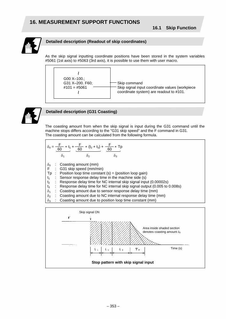
16. MEASUREMENT SUPPORT FUNCTIONS16.1 Skip Function
– 353 –
Detailed description (Readout of skip coordinates)
As the skip signal inputting coordinate positions have been stored in the system variables #5061 (1st axis) to #5063 (3rd axis), it is possible to use them with user macro.
G00 X–100.; G31 X–200. F60; Skip command #101 = #5061 Skip signal input coordinate values (workpiece
coordinate system) are readout to #101.
Detailed description (G31 Coasting)
The coasting amount from when the skip signal is input during the G31 command until the machine stops differs according to the "G31 skip speed" and the F command in G31. The coasting amount can be calculated from the following formula.
δ0 = ∗ t1 + ∗ (t2 + t3) + ∗ Tp δ0 : Coasting amount (mm) F : G31 skip speed (mm/min) Tp : Position loop time constant (s) = (position loop gain) t1 : Sensor response delay time in the machine side (s) t2 : Response delay time for NC internal skip signal input (0.00002s) t3 : Response delay time for NC internal skip signal output (0.005 to 0.008s) δ1 : Coasting amount due to sensor response delay time (mm) δ2 : Coasting amount due to NC internal response delay time (mm) δ3 : Coasting amount due to position loop time constant (mm)
Time (s)
Skip signal ON
Area inside shaded sectiondenotes coasting amount δ0
Stop pattern with skip signal input
F 60
F 60
F60
δ1 δ2 δ3
~ ~

16. MEASUREMENT SUPPORT FUNCTIONS16.1 Skip Function
– 354 –
Max. value
Min. valueCoasting amountδ0 (mm)
Relationship between coasting amount and feedrate (example)
Feedrate F (mm/min)
Detailed description (Skip coordinate readout error)
Macro variables (#5061 to ) can be used to readout the skip coordinate value determined by the following expression: Skip coordinate value = Position where skip signal is ON + ε1 + ε2
ε1 = ∗ (t1 + t2) (mm)
ε2 = ± ∗ 0.000111 (mm)
ε1 : Response delay error (mm) ε2 : Readout error (mm) F : G31 skip speed (mm/min) t1 : Sensor response delay time in the machine side (s) t2 : Response delay time for NC internal skip signal input (0.00002s)
(Note 1) Response delay error ε1 can be compensated. However, it cannot be compensated if the sensor response delay time t1 in the machine side fluctuates.
(Note 2) Readout error ε2 is an operation error in the NC and cannot be compensated.
(Note 3) The minimum value of readout error ε2 is ± 0.0005mm.
F 60
F 60

16. MEASUREMENT SUPPORT FUNCTIONS16.1 Skip Function
– 355 –
Readout error comes within shaded section.
Readout error ε (mm)
Feedrate F (mm/min)
Relationship between readout error and feedrate
Examples of coasting amount compensation
(1) Compensating for skip signal input coordinate value
#110 = Skip feedrate ; #111 = Response delay time t1; G31 X100. F100; Skip command G04; Machine stop check #101 = #5061; Skip signal input coordinate readout #102 = #110∗#111/60; Coasting amount based on response delay time #105 = #101–#102; Skip signal input coordinates
(2) Compensating for workpiece coordinate value
#110 = Skip feedrate ; #111 = Response delay time t1; #112 = Position loop time constant Tp; G31 X100. F100; Skip command G04; Machine stop check #101 = #5061; Skip signal input coordinate readout #102 = #110∗#111/60; Coasting amount based on response delay time #103 = #110∗#112/60; Coasting amount based on position loop time
constant #105 = #101–#102–#103; Skip signal input coordinates
~ ~
~ ~

16. MEASUREMENT SUPPORT FUNCTIONS16.2 Multi-step Skip Function
– 356 –
16.2 Multi-step Skip Function; G31
Function and purpose
During linear interpolation by the skip command (G31), skipping can be executed according to the conditions of the skip signal command P1. With separate systems, when multi-step skip functions are commanded simultaneously, if the input skip signals are the same, the simultaneous skip operation is executed. If the input skip signals are different, the skip operation is executed according to their respective skip signals. The skip operation is the same as the normal skip command (without G31 P command.)
Skip signal 1
Skip signal 1
Sys
tem
1S
yste
m 2
When both system 1 and system 2 have the same skip signal
Skip signal 1
Skip signal 2
Sys
tem
1S
yste
m 2
When system 1 and system 2 have separate skip signals
During the dwell command (G04) , the remaining dwell time is canceled with the skip conditions set by the parameters, and the next block is executed. In the same manner, in the speed dwell the remaining speed is also canceled, and the next block is executed.

16. MEASUREMENT SUPPORT FUNCTIONS16.2 Multi-step Skip Function
– 357 –
Command format
G31 Xx Zz αα Pp Ff ;
Xx Zz αα Command format axis coordinate word and target coordinate value Pp Skip signal command (see table below) Ff Feedrate (mm/min)
(1) The skip speed is issued with command speed F. Note that the F modal is not updated.
(2) The skip signal command is issued with the skip signal command P. P is commanded in the range of 1 to 255. When the command range is exceeded, a program error will occur.
Skip signal command Valid skip signals P 8 7 6 5 4 3 2 1 1 2
3 4
5 6
7 8
253 254
255
(Note) The number of skip signal points differ according to the machine type.
~ ~
~ ~
~~
~~
~~
~~
~~
~~
~ ~
~ ~

16. MEASUREMENT SUPPORT FUNCTIONS16.3 Automatic Tool Length Measurement
– 358 –
16.3 Automatic Tool Length Measurement; G37
Function and purpose
These functions issue the command values from the measuring start position as far as the measurement time, move the tool in the direction of the measurement position, stop the machine once the tool has arrived at the sensor, cause the NC system to calculate automatically the difference between the coordinate values at that time and the coordinate values of the commanded measurement position and provide this difference as the tool offset amount. When offset is already being applied to a tool, it moves the tool toward the measurement position with the offset still applied, and if a further offset amount is generated as a result of the measurement and calculation, it provides further offset of the present offset amount. If there is only one type of offset amount, this is automatically compensated for; if there is distinction between a tool length offset amount and wear offset amount, the wear amount is automatically compensated for.
Command format
G37 α_ R_ D_ F_;
α Measuring axis address and coordinates of measurement position ・・・・ X, Y, Z R This commands the distance between the measurement position and
point where the movement is to start at the measuring speed. (Radial value fixed/incremental value)
D This commands the range within which the tool is to stop. (Radial value fixed/incremental value)
F This commands the measuring feedrate. When R_, D_ or F_ is omitted, the value set in the parameter is used
instead. <Parameter> ("T-leng measure" on Setup param screen) • Auto TLM speed (Measuring feedrate (Fp)) 0 to 60000 [mm/min] • zone r (Deceleration range r) 0 to 99999.999 [mm] • zone d (Measurement range d) 0 to 99999.999 [mm]

16. MEASUREMENT SUPPORT FUNCTIONS16.3 Automatic Tool Length Measurement
– 359 –
Detailed description
(1) Operation with G37 command
Rapid traverse rate
Allowablemeasuring range
Alarm stop (P607)
Alarm stop (P607)
Normal completion
Operation 2
Operation 1
Offset amountDistance
Speed
Or no detection
: Sensor output
: Stop point
: Measuring position
Operation 3
(A) (B) (C) (D)
(2) The sensor signal (measuring position arrival signal) is used in common with the skip signal. (3) The feedrate will be 1mm/min if the F command and parameter measurement speed are 0. (4) During the synchronous feed mode, the tool moves by synchronous feed [mm/rev]. (5) An updated offset amount is valid unless it is assigned from the following T command of
the G37 command. (6) Excluding the corresponding values at the PLC side, the delay and fluctuations in the
sensor signal processing range from 0 to 0.2ms at the NC side only. As a result, the measuring error shown below is caused.
Maximum measuring error [mm] = Measuring speed [mm/min] × 1/60 × 0.2 [ms]/1000 (7) The machine position coordinates at that point in time are read by sensor signal detection,
and the machine will overtravel and stop at a position equivalent to the servo droop. Maximum overtravel [mm] = Measuring speed [mm/min] × 1/60 × 1/Position loop gain [1/s] The standard position loop gain is 33 [1/s].
Precautions
(1) Program error "P600" results when G37 is commanded by an NC system which is not
provided with the tool length measurement option. (2) Program error "P604" results when no axis has been commanded in the G37 block or
when two or more axes have been commanded. (3) If the T code is not commanded in the G37 block, the program error "P605" will occur.
Note that if the last one digit or last two digits of the T code is 0, the program error "P606" will occur.
(4) Program error "P606" results when the T code is not commanded prior to the G37 block. Even when the T code has been commanded, program error "P606" occurs when the last one or two digits of the T code are zero.

16. MEASUREMENT SUPPORT FUNCTIONS16.3 Automatic Tool Length Measurement
– 360 –
(5) Program error "P607" results when the sensor signal was input outside the allowable measuring range or when the sensor signal was not detected even upon arrival at the end point. However, with operation 3 in the example of the above figure, measurement is considered to be normal when area (B) is not present.
(6) When a manual interrupt is applied while the tool is moving at the measuring speed, a return must be made to the position prior to the interrupt and then operation must be resumed.
(7) The data commanded in G37 or the parameter setting data must meet the following conditions:
⏐Measurement point – start point⏐ > R command or parameter r > D command or parameter d
(8) When the D command and parameter d in (7) above are zero, operation will be completed normally only when the commanded measurement point and sensor signal detection point coincide. Otherwise, program error "P607" will result.
(9) When the R and D commands as well as parameters r and d in (7) above are all zero, program error "P607" will result regardless of whether the sensor signal is present or not after the tool has been positioned at the commanded measurement point.
(10) When the measuring command distance is less than the allowable measuring range, the tool will be confined to the allowable measuring range in each case.
(11) When the measuring command distance is less than the measuring speed movement distance, the tool will move at the measuring speed in each case.
(12) When the allowable measuring range is greater than the measuring speed movement distance, the tool will move across the allowable measuring range at the measuring speed.
(13) The nose R compensation must be canceled before the G37 command is issued.
(14) Even when the nose R compensation option has been provided, the nose R value and tool nose point numbers will not be considered and the tool length offset amount will be calculated. When the tool nose point numbers are to be set to 0, an amount equivalent to the nose R value should be deducted from the measured tool length offset amount. When the tool nose point numbers (tool nose shape) are 5, 6, 7 and 8, the tool length should be measured at the tip of the tool.
Measured X-axis toollength offset amount
X-axis tool length offsetamount produced bysubtracting amountequivalent to nose R value
Toolnosepoint 0
Z-axis tool length offset amount produced bysubtracting amount equivalent to nose R value
Measured Z-axis tool length offset amount
Measured X-axis tool length offset amount
Tool tip Measured Z-axis tool length offset amount
Tool nose point 8

17. MULTI-AXIS, MULTI-SYSTEM COMPOUND CONTROL FUNCTIONS
– 361 –
17. MULTI-AXIS, MULTI-SYSTEM COMPOUND CONTROL FUNCTIONS
Examples of target lathes
Turret 1
+X1
+Z1
Turret 2
+X2
+Z2
Firstspindle
Turret 1
+X1
+Z1
Turret 2
+X2
+Z2
Firstspindle
Secondspindle
The system controls two or more moving components (turrets, additional axes, etc.) simultaneously and independently as shown in the figures above.
2-spindle, 2-turret lathes
System 1 control axes: x1, z1 (turret 1) System 2 control axes: x2, z2 (turret 2)
1-spindle, 2-turret lathes

17. MULTI-AXIS, MULTI-SYSTEM COMPOUND CONTROL FUNCTIONS
– 362 –
Basics of multi-system programming
As multiple systems (turrets) move independently, the machining programs for the systems can be configured simply by designating the system numbers at the head of the programs and then by proceeding in the same way as for a 2-axis (or 3-axis) lathe. The synchronizing functions are used if the movements of the multiple systems need to be synchronized. (1) Preparing multi-system programs
A multi-system program uses the same program number for control purposes so only one tape is used. Searches during operations can be executed simply by designating the program number once.
O110; $1; : : : $2; : : : %
← Program number← System 1 program designation code
System 1 program
← System 2 program designation code
System 2 program
$1;
$3;
$2;
:
System 3 designation
System 2 designation
System 1 designation
:
Multi-system programs are prepared after the system designation codes that indicate that the systems have been inserted at the head of the programs. Refer to the manuals issued by the machine manufacturer to confirm which turret is allocated to which system. When the machining programs are input on the editing screen of the NC setting display unit, the system select menu keys are used to designate the systems. This also applies to MDI operation programs.
$1 O110
System select menu keys
System number displayed during editing
LCD display (when Edit screen is displayed)
$1 0110

17. MULTI-AXIS, MULTI-SYSTEM COMPOUND CONTROL FUNCTIONS
– 363 –
(2) System designation codes System 1 machining program designation: $1; System 2 machining program designation: $2; System 3 machining program designation: $3; : :
(a) Make the system designation code an independent command. If it is designated with other commands, that data will not be valid.
(b) The system designation code commands can be arranged in any order.
(c) When the system designation codes have been omitted, the program will be saved in the memory as the system 1 program.
CAUTION When programming a multi-system, carefully observe the movements caused by other systems' programs.

17. MULTI-SYSTEM CONTROL FUNCTIONS17.1 Synchronizing Operation between Systems
– 364 –
17.1 Synchronizing Operation between Systems
Function and purpose
The multi-axis, multi-system compound control NC system can simultaneously run multiple machining programs independently. The synchronizing-between-systems function is used in cases when, at some particular point during operation, the operations of systems 1 and 2 are to be synchronized or in cases when the operation of only one system is required.
!XXX;
!・・・・・・;
!・・・・・・;
%
!XXX;
!・・・・・・;
!・・・・・・;
%
Simultaneous and independent operation
← Synchronized operation Simultaneous and independent operation
← Synchronized operation System 2 operation only; system 1 waits
← Synchronized operation Simultaneous and independent operation
System 2 machining programSystem 1 machining program
No program

17. MULTI-SYSTEM CONTROL FUNCTIONS17.1 Synchronizing Operation between Systems
– 365 –
Command format
(1) Command for synchronizing with system n
!nLl;
$1 $2
!1L1;!2L1;
$3
!3L2; !1L2;
(2) Command for synchronizing among three systems
!n!m・・・Ll;
$1 $2
!1!3L1;
!2!3L1;
$3
!1!2L2;
Synchro-nized operation
Synchronized operation
n : System number l : Synchronizing number 01 to 9999
Synchronized operation
Synchronized operation
n, m : System number n = m l : Synchronizing number 01 to 9999

17. MULTI-SYSTEM CONTROL FUNCTIONS17.1 Synchronizing Operation between Systems
– 366 –
Detailed description
(1) When the !nLl code is issued from the system "i" program, the operation of that program
will wait until the !iLl code is issued from the system "n" program. When the !iLl code is issued, the programs of both systems "i" and "n" will start running
simultaneously.
!iL1;
!nL1;
Pi2 Pn2
Pi1 Pn1 Pm1
Pi1 Pi2
Pn1 Pn2
Pm1 (2) Synchronizing among three systems is as follows. When the !n!mLl command is issued
from the system "i" program, the system "i" program operation will wait until the !i!mLl command is issued from the system "n" program and the !i!nLl command is issued from the system "m" program. When the synchronizing commands are issued, "i", "n" and "m" programs will start operating simultaneously.
!i!mL1;!n!mL1;
Pi2 Pn2
Pi1 Pn1 Pm1
Pi1 Pi2
Pn1 Pn2
Pm1 Pm2
Pm2
!i!nL1;
System "i" System "n" System "m"
System "m" program System "n" program System "i" program
Simultaneous start
Waiting
Synchronized operation
System "i" System "n" System "m"
System "m" program System "n" program System "i" program
Simultaneous start
Waiting
Waiting
Synchronized operation
Synchronized operation

17. MULTI-SYSTEM CONTROL FUNCTIONS17.1 Synchronizing Operation between Systems
– 367 –
(3) A program error (P35) will occur if an illegal system number is commanded for the synchronization command, or if a decimal point is added to the system number issued in the synchronization command.
(Example) !2 → Program error (P35) will occur.
(4) When an M, S or T command or movement command has been issued with a synchronizing command, it will be executed after synchronizing.
(Example) !2L5 G00 X100.; G00 X100. is executed after synchronization with the second system.
(5) Synchronizing is done only while the system to be synchronized is operating automatically. If this is not possible, the synchronizing command will be ignored and operation will advance to the next block.
(6) The L command is the synchronizing identification number. The same numbers are synchronized but when they are omitted, the numbers are handled as L0.
(7) The synchronizing command designates the number of the other system number to be synchronized, and can also be issued along with its own system number.
(Example) System "i" command: !i!n!mLl;
(8) When the system number is omitted (only ! is input), system 1 will be handled as !2 and system 2 as !1. A command containing only ! cannot be used for synchronizing system 3 and the following systems. If ! is used in all systems, system 3 and the following will enter the waiting state at !, and the program will not proceed to the next block.
(9) "SYN" appears on the operating status display during synchronizing.

17. MULTI-SYSTEM CONTROL FUNCTIONS17.1 Synchronizing Operation between Systems
– 368 –
Example of synchronizing between systems
$1 $2
!1L1;
!2L1;
$3
!2!3L3;
P11P21
P13
P12
!3L4;
P14
P22
!3L2;
P23
!1!3L3;
P24
!2L2;
P31
!1!2L3;
P32
!1L4;
P33
The above programs are executed as follows:
$1
$2
$3
P21 P23 P24P22
P11 P12 P14P13
P33P31 P32
L1
L2
L3
L3
L4

17. MULTI-SYSTEM CONTROL FUNCTIONS17.2 Start Point Designation Synchronizing (Type 1)
– 369 –
17.2 Start Point Designation Synchronizing (Type 1); G115
Function and purpose
The synchronizing point can be placed in the middle of the block by designating the start point.
Command format
!nL1 G115 X_ Z_ C_ ;
!nL1 Synchronizing command G115 G command X_ Z_ C_ Start point (designated other system’s coordinate value)
Detailed description
(1) The other system starts first when synchronizing is executed.
(2) The own system waits for the other system to move and reach the designated start point, and then starts.
!G115
!
!G115
!
(3) When the start point designated by G115 is not on the next block movement path of the other system, the own system starts once the other system has reached all of the start point axis coordinates.
Example:
Own system Other system Own system Other system
Designated start point
Designated start point
Synchronized operation
Synchronized operation
: Movement : Command point : Actual start point

17. MULTI-SYSTEM CONTROL FUNCTIONS17.2 Start Point Designation Synchronizing (Type 1)
– 370 –
(4) The start point check is executed only for the axis designated by G115.
(Example) !L2 G115 X100.;
Once the other system reaches X100., the own system will start. The other axes are not checked.
(5) The following operation is executed by parameters (control parameter #8142 Start point alarm) when the start point cannot be determined by the next block movement of the other system.
(a) When the parameter is ON
Operation waits until the start point is reached by the movement in the next and subsequent blocks.
!G115
!
(b) When the parameter is OFF
The own system starts upon completion of the next block movement.
!G115
!
(6) The waiting status continues when the G115 command has been duplicated between systems.
(7) Designate the start point using the workpiece coordinates of the other system.
(8) Program error "P33" occurs when the G115 command is issued for 3 systems.
(9) The single block stop function does not apply for the G115 block.
(10) When the G115 command is issued continuously in 2 or more blocks, the block in which it was issued last will be valid.
Own system Other system
Waiting
Own system Other system

17. MULTI-SYSTEM CONTROL FUNCTIONS17.3 Start Point Designation Synchronizing (Type 2)
– 371 –
17.3 Start Point Designation Synchronizing (Type 2); G116
Function and purpose
The synchronizing point can be placed in the middle of a block by designating the start point.
Command format
!nL1 G116 X_ Z_ C_ ;
!nL1 Synchronizing command G116 G command X_ Z_ C_ Start point (designated other system’s coordinate value)
Detailed description
(1) The own system starts first when synchronizing is performed.
(2) The other system waits for the own system to move and reach the designated start point, and then starts.
!G116
!
!G116
!
(3) When the start point designated by G116 is not on the next block movement path of the own system, the other system starts once the own system has reached all of the start point axis coordinates.
Example:
Own system Other system Own system Other system
Designated start point
: Movement : Command point : Actual start point
Designated start point
Synchronized operation
Synchronized operation

17. MULTI-SYSTEM CONTROL FUNCTIONS17.3 Start Point Designation Synchronizing (Type 2)
– 372 –
(4) The start point check is executed only for the axis designated by G116.
(Example) !L1 G116 X100.;
Once the own system reaches X100., the other system will start. The other axes are not checked.
(5) The next operation is executed by parameters (control parameter #8142 Start point alarm) when the start point cannot be determined by the next block movement of the own system.
(a) When the parameter is ON
Program error "P33" occurs before the own system moves.
!G116
!
(b) When the parameter is OFF
The other system starts upon completion of the next block movement.
!G116
!
(6) Operation remains stopped when the G116 command has been duplicated between systems.
!L1 G116
!L1 G116
(7) Designate the start point using the workpiece coordinates of each system.
(8) The two other systems start when the G116 command is issued for 3 systems.
!2!3 L1 G116
!1!3 L1
!1!2 L1
(9) The single block stop function does not apply for the G116 block.
(10) When the G116 command is issued continuously in 2 or more blocks, the block in which it was issued last will be valid.
Own system Other system
Program error
Waiting
Own system Other system
Waiting
Own system Other system
Own system Other system A Other system B

17. MULTI-SYSTEM CONTROL FUNCTIONS17.4 Balance Cut Command
– 373 –
17.4 Balance Cut Command; G15, G14
Function and purpose
This function can completely synchronize the movement start timing of the system 1 and system 2 turrets.
Turret(System 1)
Turret(System 2)
Workpiece
Command format
G15; G14;
G15 Balance cut command ON (modal) G14 Balance cut command OFF (modal)
(1) G15 and G14 are modal commands. In the NC initialized state, the G14 balance cut command OFF mode is entered.
(2) When the G15 command is issued, the synchronization between systems will be maintained for all blocks until the G14 command is issued.
Detailed description
The sections of blocks enclosed by G15 and G14 are created in the machining programs for system 1 and system 2. The sections enclosed by G15 and G14 are synchronized one block at a time in each system.
<System 1>:
G15;N10 G01 X10. F100;N20 G01 X20.;
::
G14::
<System 2>:
G15;N10 G01 X10. F50;N20 G01 X20.;
::
G14::
The start timing of the$1 and $2 blocks issynchronized.

17. MULTI-SYSTEM CONTROL FUNCTIONS17.4 Balance Cut Command
– 374 –
(1) If G15 is commanded with one system, the operation will stop and wait until G15 is commanded in the other system.
(2) If G15 is commanded in both system 1 and system 2, synchronization will be carried out one block at a time until G14 is commanded.
(3) After G14 is commanded in both systems, system 1 and system 2 will operate independently.
Example of operation
・ ・
・G15G00 X40. Z0.G01 W-30. F1000G01 U40. W-70.G14G01 X100. Z50.G01 Z30.
・ ・
・G15G00 X-40. Z250.G01 W-130. F500G01 X-80. Z50. F1000G14S200G00 X-100.
・ ・ ・
・
・ ・
… (1)… (2)… (3)… (4)… (5)… (6)
(1) Balance cut is turned ON with the G15 command.
(2) (3) Processing of this block will end faster for system 1 than system 2. The system will wait for the system 2 process to end, and will shift the next block for both system 1 and system 2.
(4) The movement amount and movement speed are the same for each system, so synchronized movement will take place.
(5) Balance cut is turned OFF with the G14 command.
(6) Each system will operate independently after this.
Precautions and restrictions
(1) If G15 is commanded in one system, the system will wait for G15 to be commanded in the
other system. Synchronization will start when G15 has been commanded in both systems. If G14 is commanded first in one system, the other system will enter the waiting state. Shifting to the next block will not be possible. Thus, always match the number of blocks between the ON mode and OFF mode for both system 1 and system 2 when commanding balance cut.
G15G01 Z_ F_
G14
G15G01 Z_ F_
G14
G15G01 Z_ F_
G14
G15G01 Z_ F_
G14
<System 1> <System 2>
System 1 can shift to the next block, but system 2 will continue waiting and cannot shift to the next block.
System 1 program System 2 program
By matching the number of blocks between G15 and G14, both systems can shift to the blocks following G14.
System 1 program System 2 program
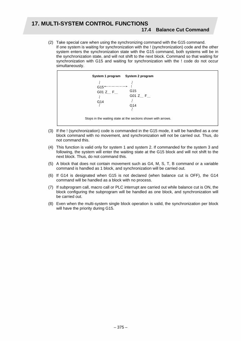
17. MULTI-SYSTEM CONTROL FUNCTIONS17.4 Balance Cut Command
– 375 –
(2) Take special care when using the synchronizing command with the G15 command. If one system is waiting for synchronization with the ! (synchronization) code and the other
system enters the synchronization state with the G15 command, both systems will be in the synchronization state, and will not shift to the next block. Command so that waiting for synchronization with G15 and waiting for synchronization with the ! code do not occur simultaneously.
G15G01 Z_ F_
G14
!G15G01 Z_ F_
G14
(3) If the ! (synchronization) code is commanded in the G15 mode, it will be handled as a one block command with no movement, and synchronization will not be carried out. Thus, do not command this.
(4) This function is valid only for system 1 and system 2. If commanded for the system 3 and following, the system will enter the waiting state at the G15 block and will not shift to the next block. Thus, do not command this.
(5) A block that does not contain movement such as G4, M, S, T, B command or a variable command is handled as 1 block, and synchronization will be carried out.
(6) If G14 is designated when G15 is not declared (when balance cut is OFF), the G14 command will be handled as a block with no process.
(7) If subprogram call, macro call or PLC interrupt are carried out while balance cut is ON, the block configuring the subprogram will be handled as one block, and synchronization will be carried out.
(8) Even when the multi-system single block operation is valid, the synchronization per block will have the priority during G15.
Stops in the waiting state at the sections shown with arrows.
System 1 program System 2 program
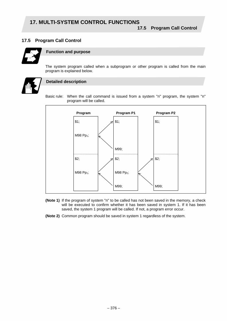
17. MULTI-SYSTEM CONTROL FUNCTIONS17.5 Program Call Control
– 376 –
17.5 Program Call Control
Function and purpose
The system program called when a subprogram or other program is called from the main program is explained below.
Detailed description
Basic rule: When the call command is issued from a system "n" program, the system "n"
program will be called.
Program
$1;
M98 Pp1;
$2;
M98 Pp1;
Program P1
$1;
M99;
$2;
M98 Pp2;
M99;
Program P2
$1;
$2;
M99;
(Note 1) If the program of system "n" to be called has not been saved in the memory, a check
will be executed to confirm whether it has been saved in system 1. If it has been saved, the system 1 program will be called. If not, a program error occur.
(Note 2) Common program should be saved in system 1 regardless of the system.

17. MULTI-SYSTEM CONTROL FUNCTIONS17.6 Cross Axis Control
– 377 –
17.6 Cross Axis Control; G110
Function and purpose
The cross machining command serves to change the system definitions of the NC control axes. For those control axes (cross axes) of which the system definitions can be changed, this command enables control from multiple systems among those systems that are separate from the basic system. Actual example: When controlling C axis which is the basic axis of system 1 by system 2
System 1 System 2 Basic definition X1 Z1 C1 X2 Z2 Cross axis C1 axis – Cross command program G110 X1 Z1; G110 X2 Z2 C1;Control axes before cross command X1, Z1, C1 X2, Z2 After cross command X1 Z1 X2 Z2 C1
X1
Z 1
X2
Z2
C1
$1
$2
Command format
G110 Xn Zm Cl ........ ;
G110 Cross machining command code X, Z, C ... Axis name n, m, l ... System number 1 to system max.
The axis names and system numbers are the basic definition names and numbers given by parameters, and the definitions are changed so that the corresponding axes can be controlled by the relevant system program. The details of the definition changes are valid from the following block.

17. MULTI-SYSTEM CONTROL FUNCTIONS17.6 Cross Axis Control
– 378 –
Example of program
Basic definition $1 X Z C $2 X Z $3 Z
$1 (System 1 program)
(1) G110 X1 Z2 C1;
:
:
(2) G110 X1 Z2;
$2 (System 2 program)
G110 X2 Z1;
:
:
G110 X2 Z1 C1;
Nosynchronizedoperation
Synchronizedoperation
Synchronizedoperation
$3 (System 3 program)
G110 Z3;
(1) Z1 and Z2 system interchange
(2) C1 axis system change
Detailed description
(1) Program error "P503" occurs when the axes corresponding to the axis names and system numbers do not exist or when an axis (set by machining parameter) has been designated which cannot be controlled by the relevant system.
(2) All of the axes controlled by the relevant system are designated. Only the designated axes can be controlled by the subsequent program.
(3) The cross machining command is required with all systems to be changed as the definitions of the axes and systems change. The NC system synchronizes operation with all the changed systems until the command is issued. After synchronized operation, it processes the changes in the definitions.
(4) Up to 5 axes can be controlled by the systems. Program error "P503" occurs when a number exceeding 5 is designated.
(5) When the same axis name has been designated in the same system, it serves as the system number for a subsequent axis.
(Example) G110 X1 Z2 Z1 ;
(6) The following will occur when another G code or address is issued in the same block.
(a) When a modal G command has been designated in the same block, the modal will be changed, but the axis address and other commands are ignored.
(b) When an unmodal G command has been designated in the same block, G110 is ignored if that command comes after G110 and the unmodal G command will be valid. On the other hand, if that command comes before G110, the unmodal G command will be ignored and G110 will be valid.
This is ignored.

17. MULTI-SYSTEM CONTROL FUNCTIONS17.6 Cross Axis Control
– 379 –
Relation with other functions
(1) Program error "P501" occurs when the cross machining command is issued in any of the
following states, so do not issue the cross machining command.
(a) Nose R mode
(b) Milling mode
(c) Balance cut mode
(d) Fixed cycle (turning, hole drilling) mode
(e) Facing turret mirror image mode (2) G modal commands
G modal commands are not changed by the cross machining command. The modals are saved by each system.
(3) Plane selection axes
The three basic axes for plane selection and the corresponding parallel axis names are saved beforehand as parameters for each system. Axes are replaced and axes are moved to other systems by the cross machining commands, but the saved plane selection axis will remain unchanged. Consider the cross machining command when saving the parameters.
(Example 1)
Basic definition: System 1 X1 Z1 System 2 X2 Z2 Cross machining command: $1 G110 X1 Z2; $2 G110 X2 Z1; Z axis replacement Basic axis parameter save
<System 1> <System 2> Basic axis Basic axis I X I X J J K Z K Z
Since the saved parameters are not changed by the cross machining command, the G18 plane axes are X1Z2 axis (system 1) and X2Z1 axis (system 2).
(Example 2)
Basic definition: System 1 X1 Z1 System 2 X2 Z2 Y2 Cross machining command: $1 G110 X1 Z1 Y2; $2 G110 X2 Z2; Y axis shifts to $1 Basic axis parameter save ・・・・・Y-axis plane is enabled even for system 1.
<System 1> <System 2> Basic axis Basic axis I X I X J Y J Y K Z K Z

17. MULTI-SYSTEM CONTROL FUNCTIONS17.6 Cross Axis Control
– 380 –
(4) Coordinate system function The reference point and machine zero point characteristic to the machine at each axis are not changed by the cross machining command. Since the workpiece coordinate and local coordinate systems are created on the basis of the machine zero point, the coordinate system zero points for each axis also remain unchanged. However, if this is considered on the XZ plane as in the figure below, the coordinate zero points of the systems are changed by cross machining.
X1
Z1
$ 1 X2
Z2
$2
5
4
3
2
1
0 0 1 2 3 4 5 6 7 8 9 10 11
X1
Z2
$1X2
Z1
$ 2
5
4
3
2
1
0
System 1 X1 Z1 System 2 X2 Z2
System 1 X1 Z1 System 2 X2 Z2
Cross machining command
$1 G110 X1 Z2; $2 G110 X2 Z1; (Z1 and Z2 are interchanged)
This means that the workpiece coordinate and local coordinate systems for programming will differ from the coordinate systems needed by the programmer because of the cross machining command. In this case, issue the coordinate system commands after the cross machining command and create new coordinate systems.
(5) Tool length and wear offset The tool length and wear offset amounts are stored for each axis even when the cross machining command is issued. Even after this command has been issued, the program can be run without change. However, the following points should be observed.
(a) The 1st and 2nd axes in each system are the axes for which the tool length and wear offset functions are valid. These functions are not valid for the 3rd and subsequent axes. Therefore, if offset is required for particular axes, issue the cross machining command so that the 1st and/or 2nd axis will apply.
(b) When the tool length offset amount is entered as the amount from the programmed coordinate zero point up to the tool nose, it will not be applied properly if the coordinate zero point differs from the cross machining command. First, set an offset amount that meets the new coordinate zero point, and then issue the T command.
Old offsetamount
New coordinatesystem
Old coordinatesystem
New offset amount

17. MULTI-SYSTEM CONTROL FUNCTIONS17.6 Cross Axis Control
– 381 –
(6) Setting and display functions There are two setting and display functions, aligned setting and display after the cross machining command, and setting and display with the basic definitions unchanged. These are known as cross setting and display and basic definition setting and display. Refer to the following table to confirm which functions apply to which items.
Setting and display item Cross setting and
display Basic definition
setting and displayPresent position, workpiece coordinate position, machine position, program position, remaining command, manual interrupt amount, error compensation amount
Tool wear offset Tool length offset Workpiece coordinate offset User parameter: axis parameter User parameter: setup 2 (barrier data) Graphic display Servo monitor display Machine parameter: basic specification 1 Machine parameter: axis specification Machine parameter: zero point return Machine parameter: servo Alarm system/axis display Nose R, wear
(7) Manual operation The manual operation axes can be operated manually only when they are part of a basic definition system. An operation error will occur when an axis selected as a feed axis is used by the cross machining command of another system. Select the feed axis again after that axis has returned to the basic definition axis. (Example)
$1 $2 Basic definition After cross machining command
X1 Z1 C1 X2 Z1 C1
X2 Z2 X1 Z2
When manual operation is to be set for system 2 while only system 1 is operating automatically, it is possible to manually operate the 1st axis of the system 2 when the basic definition applies. However, this will not be possible after the cross machining command.
(a) Manual interrupt during automatic operation Whether the operation of an axis of another system that is cross machining using the cross machining command is to be enabled by a manual interrupt during automatic operation depends on the selection of the parameter (setting made by machine parameter). • When the parameter is invalid
The cross machining axis cannot be operated by the manual interrupt. • When the parameter is valid
Even the cross machining axis can be operated by the manual interrupt. Select the axis in the basic definition system for operating the cross machining axis.
(Example) The X1 axis in system 2 moves when the 1st axis in system 1 is selected under the following conditions:
Basic definition axes System 1 X1, Z1 System 2 X2, Z2 With cross machining command System 1 X2, Z1 System 2 X1 Z2 (Note) Jog feed and step feed are valid with manual interrupt; handle feed and optional
feed are not valid.

17. MULTI-SYSTEM CONTROL FUNCTIONS17.6 Cross Axis Control
– 382 –
(8) Automatic operation (a) During automatic operation start
During automatic operation start, the first block is executed after a return is made to the basic definition axes. This means that if the system to be operated automatically does not have the basic definition axes, it waits until it does have them. In other words, the first automatic operation block is the same as that for the cross machining command that is set to the basic definition axes of the relevant system. (Example) System 1 operation with basic definition axes of X1, X2, C1 for system 1
and X2, Z2 for system 2 System 1 machining program System 2 machining program
G28 X Z C; G00 X100; :
G28 X Z; (i) : G110 X1 Z2; (ii) : G110 X2 Z2; (iii) :
When the block before (iii) from (ii) in the system 2 machining program is executed, the synchronized operation occurs until (iii) in the system 2 machining program is reached even if the system 1 machining program is operated automatically. (This is the same as issuing G110 X1 Z1 C1; at the head of the system 1 machining program.)
(b) During reset Reset system axes return to the basic definitions. However, if a reset system basic definition axis is being used by another system, it will not return but will be set to the reset mode. The axis will return to the basic definition depending on whether the system in which it is used issues a cross machining command or conducts resetting. (All systems will have basic definition axes when they end automatic operation.) (Example) Resetting system 1 when X1, Z1 and C1 of system 1, X2 and Z2 of
system 2, and X3 of system 3 are the basic definition axes System 1 machining program System 2 machining program
: G110 X3 Z2 C1 ; : G01 X100 ; (i)
: G110 X2 Z1 ; : G01 X100 ; (ii) :
When systems 1 and 2 are operating automatically and system 3 is in the reset mode, the axes in system 1 in the reset mode will be X1 Z2 C1 when system 1 is reset while system 1 is executing block (i) and system 2 is executing block (ii) (Z1 is used by system 2.)
(c) When issuing the cross machining command to an axis in a system operating in the manual mode When using an axis in a system operating manually with a cross machining command from another system, that system will execute the cross machining command. The operation of the manually operating system will be synchronized until it is no longer in the manual operation mode, and then the single block stop mode will be entered. Perform the start-up procedure again. (Example) When the cross machining command is issued by system 2 with system
1 operating in the manual mode System 2 machining program
G110 X1 Z2;
:
System 1 waits until it is no longer in themanual operation mode and then the singleblock stop mode is established.

17. MULTI-SYSTEM CONTROL FUNCTIONS17.7 Control Axis Synchronization
– 383 –
17.7 Control Axis Synchronization ; G125
Function and purpose
This command can be used to synchronize the operation of an axis in any selected system with an axis in another system.
Command format
(1) Synchronization control ON
G125 D_ = H_
D (slave axis name) Command the axis to be moved as the slave axes during synchronization control.
H (master axis name) Command the axis to be the reference for the slave axis.
(2) Synchronization control OFF
G125 Slave axis name
Detailed description
(1) Issue the slave axis and master axis commands on the basis of the basic axis definitions.
System 1 System 2 System 3[Axis name] X Z X Z X Z [Basic axis definition] X1 Z1 X2 Z2 X3 Z3
(2) When issuing the synchronous and synchronous cancel commands, the synchronous command for establishing the timing between the slave axis and master axis must be issued in the block before the synchronous and synchronous cancel command.
(3) The synchronous and synchronous cancel commands are valid when both the slave and master axes are stopped. When issuing the synchronous and synchronous cancel commands from a system that does not contain the master axis, a dwell command should be issued in the block after the block with the synchronous command for the system that contains the master axis. If the dwell command is not issued, the synchronization will be executed after the master axis has stopped. During synchronization, do not issue movement command to the slave axis.
(4) By adding the "–" sign to the master axis in the control axis synchronous command (G125), the slave axis can be synchronized in the reverse direction with respect to the master axis.
(5) During synchronization, manual and automatic movement commands cannot be issued for the slave axis.
Whether an alarm should occur or the command should be invalidated if an axis movement command is issued is set in Base common parameter "syncch".

17. MULTI-SYSTEM CONTROL FUNCTIONS17.7 Control Axis Synchronization
– 384 –
(6) The soft limit, chuck barrier and hardware OT of the synchronous axis are checked by the machine coordinate system. All systems stop when soft limit, chuck barrier or hardware OT applies even to one axis. During simulation and machine lock, however, the soft limit, chuck barrier and hardware OT are not checked.
(7) An alarm occurs when dog-type zero point return is done during synchronization.
(8) The coordinate system of the slave axis during control axis synchronization does not move with the master axis but follows the coordinate system before the synchronization.
(9) An alarm occurs when a command accompanying tool compensation or coordinate system shift of the slave axis is issued during synchronization.
(10) An alarm occurs if the commanded axis does not exist as the basic definition axis or if the slave axis and master axis are not parallel axes (with the same axis name).
(11) An alarm occurs when executing a synchronous command that includes two or three axes that are being superimposed.
(12) An alarm occurs when the cross machining command is issued to the slave axis or master axis during synchronization.
(13) Two or more synchronous commands cannot be issued in the G125 block. An alarm will occur if two or more commands are issued.
(14) When one axis has been synchronized with another axis without the synchronous cancel command being issued, the previous synchronization will be canceled.
[System 1] [System 2] [System 3]
Machining program ↓ N10 !L1; N11 G125 X2=X1; ↓ N30 !2!3L2; ↓ ↓
Machining program ↓ N5 !L1; ↓ ↓ N20 !1!3L2; ↓ ↓
No movementcommand forsynchronousaxis
Machining program ↓ ↓ ↓ ↓ N15 !1!2L2; N16 G125 X2=X3; ↓
• The X2 axis is synchronized with the X1 axis in the N11 block of system 1, the X2 axis synchronizing with X1 axis in the N16 block of system 3 is canceled, and the X2 axis is synchronized with X3 axis.
Example of program
(1) When issuing the command from a system containing the master axis
(a) Forward direction synchronization [System 1] [System 2] Machining program ↓ N9 !L1; N10 G125 X2=X1; ↓ N19 !L2; N20 G125 X2 ; ↓
Machining program ↓ N5 !L1; ↓ ↓ N10 !L2; ↓
No movement command forslave axis
• The X2 axis is synchronized with the X1 axis in the N10 block of system 1, and the X2 axis synchronization is canceled in the N20 block of system 1.

17. MULTI-SYSTEM CONTROL FUNCTIONS17.7 Control Axis Synchronization
– 385 –
(b) Reverse direction synchronization
[System 1] [System 2] Machining program ↓ N14 !L1; N15 G125 X2=X1; ↓ N24 !L2; N25 G125 X2; ↓
Machining program ↓ N10 !L1; ↓ ↓ N15 !L2; ↓ ↓
No movement command forslave axis
• The X2 axis is synchronized in the reverse direction with the X1 axis in the N15 block of system 1, and the X2 axis synchronization is canceled in the N25 block of system 1.
(c) When issuing the command from a system that does not contain the master axis
[System 1] [System 2] [System 3] Machining program ↓ N9 G4 X0; N10 !2!3L1; ↓ N39 G4 X0; N30 !2!3L2; ↓ ↓
Machining program ↓ N15 !1!3L1; ↓ ↓ ↓ N40 !1!3L2; ↓ ↓
Machining program ↓ N5 !1!2L1; N16 G125 X2=X1; ↓ ↓ N10 !1!2L2; N11 G125 X2; ↓
• The X2 axis is synchronized with the X1 axis in the N6 block of system 3, and the X2 axis synchronization is canceled in the N11 block of system 3.
No movement command for slave axis
17. MULTI-SYSTEM CONTROL FUNCTIONS17.8 Spindle Synchronization
– 386 –
17.8 Spindle Synchronization; G114.1, G113
Function and purpose
In a machine having two spindles, serially connected, the rotation speed and phase of one spindle are controlled in synchronization with the rotation of the other spindle. This is used when the rotation speed of two spindles need to be matched, such as when using the second spindle to grasp a workpiece grasped by the first spindle, or to change the spindle rotation speed when one workpiece is graphed by both the first and second spindles.
Command format
(1) Spindle synchronization control command
The master spindle and slave spindle are designated, and both spindles are synchronized. By commanding the slave spindle phase shift amount, the phases of the master spindle and slave spindle can be aligned.
G114.1 H_ D_ R_ ; Spindle synchronous control ON
H Master spindle D Slave spindle R Slave spindle phase spindle amount
(2) Spindle synchronization control cancel command
The synchronous state of the two spindles rotating in synchronization with the spindle synchronous command is canceled.
G113; Spindle synchronization control OFF

17. MULTI-SYSTEM CONTROL FUNCTIONS17.8 Spindle Synchronization
– 387 –
Add- ress
Meaning of address
Command range (unit) Remarks
H Master spindle Set the number of the spindle to be used as the master spindle.
1 to 6 Command machine parameter Sname value
• If there is no command, a program error will occur. (P33 Format error)
• If the same value as the D command is commanded, a program error will occur. (P33 Format error)
• If a spindle that is not serially connected (HDLC connection), a program error will occur. (P33 Format error)
D Slave spindle Set the number of the spindle to be synchronized with the master spindle.
1 to 6 or −1 to −6 Command the machine parameter Sname value or the Sname value with – sign value
• If there is no command, a program error will occur. (P33 Format error)
• If the same value as the H command is commanded, a program error will occur. (P33 Format error)
• The rotation direction of the slave spindle in respect to the master spindle is commanded with the D sign.
• If a spindle that is not serially connected (HDLC connection), a program error will occur. (P33 Format error)
R Slave spindle phase shift amount
Set the shift amount from the slave spindle's reference point (one rotation signal).
0 to 359.999 (°) or 0 to 359999 (°×10–3)
• The commanded shift amount is applied in the clockwise direction of the spindle.
• The minimum resolution of the commanded shift amount is as follows.
For semi-closed : 360/4096 (°) For full closed : (360/4096) ∗ K (°) K: Spindle and encoder gear ratio.• If there is no R command, phase
alignment will not be carried out.
(Note 1) If the G164 command is issued to a spindle during the spindle synchronization (G114.n) mode, or if the G114.n command is issued to a spindle during the spindle superimposition mode, an operation error will occur. (M01 operation error 1005)
(Note 2) If a value exceeding the command range is commanded, a program error will occur. (P35 Setting value range over)
(Note 3) A program error will occur if H or D is not commanded. (P33 Format error)

17. MULTI-SYSTEM CONTROL FUNCTIONS17.8 Spindle Synchronization
– 388 –
Rotation speed and rotation direction
(1) The rotation speed and rotation direction of the master spindle and slave spindle during
spindle synchronization control are the rotation speed and rotation direction commanded to the master spindle. Note that the slave spindle's rotation direction can be set to the opposite of the master spindle's direction from the program.
(2) The master spindle's rotation speed and rotation direction can be changed during spindle synchronization control. Constant surface speed control of the master spindle is also possible.
(3) The slave spindle's rotation command is valid during spindle synchronization. When the spindle synchronization control is commanded, if neither a forward run nor a reverse run command is issued to the slave spindle, the slave spindle will not start rotating, and instead will wait for synchronization. The slave spindle will start rotating when a forward run or reverse run command is input in this state. Note that the slave spindle's rotation direction will be that commanded from the program. If spindle stop is commanded (if both forward run and reverse run are turned OFF) to the slave spindle during spindle synchronization control, the slave spindle rotation will stop.
(4) The rotation speed command (S command) and the constant surface speed control are invalid for the slave spindle during the spindle synchronization control mode. Note that the modal will be updated, so these will be validated when spindle synchronization is canceled.

17. MULTI-SYSTEM CONTROL FUNCTIONS17.8 Spindle Synchronization
– 389 –
Relative position spindle synchronization control (Rotation synchronization)
(1) If the relative position spindle synchronization control command (no R address command)
is issued with the G114.1 command, the slave spindle rotating at a random rotation speed will accelerate or decelerate to the rotation speed pre-commanded for the master spindle, and will enter the relative position spindle synchronization control state.
(2) If the master spindle's command rotation speed is changed during relative position spindle synchronization control, the synchronization state will be maintained following the spindle acceleration/deceleration time constants set in the parameters, and the commanded rotation speed will be attained.
(3) Constant surface speed control can be applied to the master spindle even when two spindles are grasping one workpiece in the relative position spindle synchronization control state.
(4) The rotation speed command (S command) and the constant surface speed control are invalid for the slave spindle during the spindle synchronization control mode. Note that the modal will be updated, so these will be validated when spindle synchronization is canceled.
(5) The following type of operation will take place.
M23 S2=750; : M03 S1=1000; : G114.1 H1 D-2; : S1=500; : G113;
・・・・Forward run second spindle (slave spindle) at 750r/min. (Speed command)
・・・・Forward run first spindle (master spindle) at 1000r/min. (Speed command)
・・・・Synchronize second spindle (slave spindle) to first spindle (master spindle) with reverse run.
・・・・Change the first spindle (master spindle) rotation speed to 500r/min. ・・・・Cancel spindle synchronization.
(1) (2) (3) (4) (5)
1250
1000
750
500
250
-250
-500
-750
-1000
0
(4)(1) (2) (3) (5)
Time
Master spindle Slave spindle
Reverse run
Forward run
Rotation speed

17. MULTI-SYSTEM CONTROL FUNCTIONS17.8 Spindle Synchronization
– 390 –
Absolute position spindle synchronization control (Phase synchronization)
(1) If the absolute position spindle synchronization control command (with R address
command) is issued with the G114.1 command, the slave spindle rotating at a random rotation speed will accelerate or decelerate to the rotation speed pre-commanded for the master spindle, and will enter the relative position spindle synchronization control state. The phase is aligned so that the rotation phase commanded with the R address is reached, and the absolute position spindle synchronization state is entered.
(2) If the master spindle's command rotation speed is changed during absolute position spindle synchronization control, the synchronization state will be maintained following the spindle acceleration/deceleration time constants set in the parameters, and the commanded rotation speed will be attained.
(3) Constant surface speed control can be applied to the master spindle even when two spindles are grasping one workpiece in the absolute position spindle synchronization control state.
(4) The following type of operation will take place.
M23 S2=750; : M03 S1=1000; : G114.1 H1 D-2 Rxx; : S1=500; : G113;
・・・ Forward run second spindle (slave spindle) at 750r/min. (Speed command)
・・・ Forward run first spindle (master spindle) at 1000r/min. (Speed command)
・・・ Synchronize second spindle (slave spindle) to first spindle (master spindle) with reverse run. Shift slave spindle phase by R command value.
・・・ Change the first spindle (master spindle) rotation speed to 500r/min.
・・・ Cancel spindle synchronization.
(1) (2) (3) (4) (5)
1250
1000
750
500
250
-250
-500
-750
-1000
0
(4)(1) (2) (3) (5)
Phase alignment
Time
Master spindle Slave spindle
Reverse run
Forward run
Rotation speed

17. MULTI-SYSTEM CONTROL FUNCTIONS17.8 Spindle Synchronization
– 391 –
Precautions for programming
(1) To enter the relative position spindle control mode while the master spindle and slave
spindle are chucking the same workpiece, turn the master spindle/slave spindle rotation commands ON before turning the spindle synchronization control mode ON.
(Program example)
$1
:
M6;
:
!3;
M5 S1=0;
:
:
M3;
!3;
:
:
:
S1=1500;
......First spindle chuck
close
......First spindle stops at S=0
......First spindle rotation command ON
......Synchronous rotation at
S = 1500
$3
:
:
M25 S2=0;
:
!1;
M15;
M24;
:
:
!1;
G114.1 H1 D-2;
......Second spindle stops at
S=0
......Synchronized operation
......Second spindle chuck close
......Second spindle rotation command ON
......Synchronized operation
......Relative position spindle synchronization control mode ON
(2) To chuck the same workpiece with the master spindle/slave spindle during the absolute position spindle synchronization control mode, chuck after aligning the phases. If the phases are aligned after chucking the same workpiece, an excessive load will be applied on the workpiece, and correct operation will not be possible.
(Program example)
$1
:
M6;
:
M3 S1=1500;
:
:
:
:
:
:
......First spindle chuck
close ......First spindle rotation
command ON (S=1500)
$3
:
:
:
G114.1 H1 D-2
R0;
:
M24;
:
M15;
:
......Absolute position spindle
synchronization control mode ON
......Second spindle rotation
command ON
......Second spindle chuck close (Note 1)
(Note) Close the chuck after confirming that the synchronization complete signal (X269) has turned ON (phase alignment complete).

17. MULTI-SYSTEM CONTROL FUNCTIONS17.8 Spindle Synchronization
– 392 –
CAUTION Do not turn the slave spindle rotation command OFF when the master spindle/slave spindle are both chucking the same workpiece in the spindle synchronization control mode. A hazardous state will be created as the slave spindle will stop.
Precautions
(1) The spindle rotating with spindle synchronization control will stop when emergency stop is
applied. The spindle synchronization control mode will be canceled.
(2) The rotation speed clamp during spindle synchronization control will follow the smaller clamp value set for the master spindle or slave spindle.
(3) Orientation of the master spindle and slave spindle is not possible during the spindle synchronization control mode. To carry out orientation, cancel the spindle synchronization control first.
(4) The rotation speed command (S command) is invalid for the slave spindle during the spindle synchronization control mode. Note that the modal will be updated, so this will be validated when spindle synchronization control is canceled.
(5) The constant surface speed control is invalid for the slave spindle during the spindle synchronization control mode. Note that the modal will be updated, so this will be validated when spindle synchronization is canceled.
(6) The rotation speed (S command) and constant surface speed control for the slave spindle will be validated when spindle synchronization control is canceled. Thus, the slave spindle may carry out different operations when this control is canceled.

17. MULTI-SYSTEM CONTROL FUNCTIONS17.9 Tool/Spindle Synchronization 1 (Polygon)
– 393 –
17.9 Tool/Spindle Synchronization 1 (Polygon); G114.2, G113
Function and purpose
In a machine having a rotary tool controlled with a serial connection and having a spindle controlled with a serial connection as the workpiece axis, polygon machining can be carried out by controlling the workpiece axis rotation in synchronized with the rotation of the rotary tool axis. The serial connection control axis spindle and rotary tool axis can be carried out with MDS-∗-SP or MDS-∗-SPJ2.
Command format
(1) Polygon machining mode command
This command sets the polygon machining mode that rotates the two axes in synchronization with differing speeds by designating the rotary tool axis and workpiece axes and the rotation ratio (No. of rotary tool teeth and No. of workpiece angles) of the two designated axes (spindle and spindle).
G114.2 H_ D_ E_ L_ R_; Tool/spindle synchronization control 1 (polygon machining mode) ON
H Rotary tool axis D Workpiece axis E Rotary tool axis rotation ratio L Workpiece axis rotation ratio R Workpiece axis phase shift amount
(2) Polygon machining mode cancel command
This command cancels the synchronization state of rotating two spindles by the spindle synchronization command.
G113; Tool/spindle synchronization control 1 (polygon machining mode) OFF

17. MULTI-SYSTEM CONTROL FUNCTIONS17.9 Tool/Spindle Synchronization 1 (Polygon)
– 394 –
Add- ress
Meaning of address
Command range (unit) Remarks
H Rotary tool axis Select the spindle number of the rotation axis.
1 to 6 Command machine parameter Sname value
1. If there is no command, a program error will occur. (P33 Format error)
2. If the same value as the D command is commanded, a program error will occur. (P33 Format error)
3. If a spindle that is not serially connected (HDLC connection), a program error will occur. (P33 Format error)
D Workpiece axis Select the spindle number of the workpiece axis.
1 to 6 or −1 to −6 Command the machine parameter Sname value or the Sname value with – sign value
1. If there is no command, a program error will occur. (P33 Format error)
2. If the same value as the H command is commanded, a program error will occur. (P33 Format error)
3. The rotation direction of the workpiece axis in respect to the rotary tool axis is commanded with the D sign.
4. If a spindle that is not serially connected (HDLC connection), a program error will occur. (P33 Format error)
E Rotary tool axis rotation ratio
Set the rotation ratio (No. of rotary tool gear teeth) of the rotary tool axis.
1 to 999 1. If there is no command, the rotation ratio will be interpreted as 1.
L Workpiece axis rotation ratio
Set the rotation ratio (No. of workpiece corners) of the workpiece axis.
1 to 999 1. If there is no command, the rotation ratio will be interpreted as 1.
R Workpiece axis phase shift amount
Set the shift amount from the workpiece axis’ reference point (one rotation signal).
0 to 359.999 (°) 1. The commanded shift amount is applied in the clockwise direction of the spindle.
2. The minimum resolution of the commanded shift amount is as follows.
For semi-closed : 360/4096 (°) For full closed : (360/4096) ∗ K (°) K: Spindle and encoder gear ratio.3. If there is no R command, phase
alignment will not be carried out.
(Note 1) If a value exceeding the command range is commanded, a program error will occur. (P35 Setting value range over)

17. MULTI-SYSTEM CONTROL FUNCTIONS17.9 Tool/Spindle Synchronization 1 (Polygon)
– 395 –
Precautions for programming
(1) The axis address (X, Z, C, U, W) command in the same block as G114.2 will be ignored. (Example) G114.2 ・・・ X_; (2) If a modal is commanded in the same block as G114.2, the modal will be updated. (Example) G114.2 ・・・ G01_; (3) If a miscellaneous command (M, S, T) is commanded in the same block as G114.2, the
miscellaneous command will be executed simultaneously with the change to the rotary tool machining mode.
(Example) G114.2 ・・・ M03; (4) If there is a group 00 G code command in the same block as G114.2, the G code
commanded last in the block will have the priority. (Example) G114.2 ・・・ G04 P30;
(5) The tool/spindle synchronization control 1 (polygon machining) mode cannot be commanded
during the spindle synchronization control (spindle rotation synchronization) mode or the tool/ spindle synchronization control 2 (hobb machining) mode.
Only one of the three types of spindle synchronization control can be commanded at once.
Ignored.
The group 01 modal is set to G01.
M03 is executed simultaneously with G114.2.
G04 P30 is executed.

17. MULTI-SYSTEM CONTROL FUNCTIONS17.9 Tool/Spindle Synchronization 1 (Polygon)
– 396 –
Example of program
:
:
M03 S1=0;
Txx 00;
M83 S4=500;
G00 X40. Z-5.;
:
: G114.2 H4 D1 E1 L10 R0;
......First spindle forward run
......Rotary tool selection
......Fourth spindle forward run
......Tool/spindle synchronization 1 (polygon machining mode) ON Rotary tool axis: Fourth spindle Workpiece axis: First spindle No. of rotary tool gear teeth: 1 Rotation ratio: No. of workpiece corners as 10 Workpiece axis phase shift amount: 0°.
As S1 forward run, rotation in synchronized with S4 starts.The phase is aligned with shift amount 0°. The S1 rotation speed is 50 r/min (S4 : S1 = 10 : 1).
G99;
M
G00 X18.;
G01 Z20. F0.1;
G00 X40.;
Z-5.;
:
:
G00 X14.;
G01 Z20. F0.1;
G00 X40.;
Z-5.;
G113;
M85;
M05;
:
......Synchronous feed mode selection
......Spindle synchronization complete confirmation
......First cut in
Z axis feedrate is 0.1mm per workpiece axis rotation
......Final cut in
Z axis feedrate is 0.1mm per workpiece axis rotation
......Spindle synchronization cancel
......Fourth spindle stop
......First spindle stop

17. MULTI-SYSTEM CONTROL FUNCTIONS17.9 Tool/Spindle Synchronization 1 (Polygon)
– 397 –
Rotation speed and rotation direction
The rotary tool axis and workpiece axis rotation speed and rotation direction during tool/spindle synchronization 1 (polygon machining) are as follows. (1) The rotation speed and rotation direction of rotary tool axis are the rotation speed
commanded with the S command and the rotation direction commanded with the M command, etc., for the spindle selected as the rotary tool axis.
(2) The workpiece axis rotation speed is determined by the No. of rotary tool gear teeth and No. of workpiece corners commanded with G114.2.
Sw = Sh ∗
Sw : Workpiece axis rotation speed (r/min) Sh : Rotary tool axis rotation speed (r/min) L : Rotary tool axis rotation ratio (No. of rotary tool gear teeth) E : Workpiece axis rotation ratio (No. of workpiece corners)
(3) The workpiece axis rotation direction is determined by the sign of the address D commanded with G114.2. In other words, when the D sign is "+", the workpiece axis rotates in the same direction as the rotary tool axis, and when "−", the workpiece axis rotates in the reverse direction of the rotary tool axis.
(4) After tool/spindle synchronization 1 (polygon machining) is commanded, the relation of the rotary tool axis and workpiece axis rotation is held in all operation modes of automatic and manual modes until spindle synchronization cancel (G113) is commanded or until the spindle synchronization cancel signal is input.
Even during feed hold, the rotary tool axis and workpiece axis synchronization state is held.
Polygon machining when workpiece axis is spindle
When using the first to sixth spindles as the workpiece axis, the workpiece axis will be controlled in the following manner. (1) When the tool/spindle synchronization 1 (polygon machining) mode is commanded, if
neither a forward run command nor a reverse run command is input for the workpiece axis, the workpiece axis will not start rotating even if the polygon axis is rotating, and instead will wait for synchronization. If a forward run command or reverse run command is input for the workpiece axis in this state, the workpiece axis will start rotation.
(2) If spindle stop is commanded (both forward run command and reverse run command are turned OFF) in respect to the workpiece axis during the tool/spindle synchronization 1 (polygon machining) mode, the workpiece axis rotation will stop even when the rotary tool axis is rotating.
(3) The rotation speed command (S command) and constant surface speed command are invalid in respect to the workpiece axis during the tool/spindle synchronization 1 (polygon machining) mode. Note that the modal will be updated, so these will be validated after the tool/spindle synchronization is canceled.
(4) If a rotary tool axis rotation speed that exceeds the workpiece axis maximum rotation speed is commanded, the rotary tool axis rotation speed will be clamped so that the workpiece axis rotation speed does not exceed the workpiece axis maximum rotation speed.
EL

17. MULTI-SYSTEM CONTROL FUNCTIONS17.9 Tool/Spindle Synchronization 1 (Polygon)
– 398 –
Acceleration/deceleration control
(1) The rotary tool axis will accelerate or decelerate following the spindle synchronization
acceleration/deceleration time constant (spt) of the spindle selected as the rotary tool axis.
Phase alignment control
(1) If the tool/spindle synchronization control 1 (with R command) is commanded with the
G114.2 command, the workpiece axis rotating at a random speed will accelerate or decelerate to the speed following the rotary tool axis and workpiece axis rotation ratio command, and the tool/spindle synchronization control state will be entered. After that, the phase will be aligned to match the rotation phase commanded with the R address.
(2) The workpiece axis phase shift amount is commanded as the shift amount from the workpiece axis' reference point (one rotation signal). There is no shift amount in respect to the rotary tool axis.
(3) If the rotary tool axis' command rotation speed is changed during the tool/spindle synchronization control state, acceleration/deceleration following the acceleration/ deceleration time constant that was set in the parameter while maintaining the synchronous state, and then the commanded rotation speed will be attained.
(4) The following type of operation will take place.
M03 S1=0; : Txx 00; M83 S4=500; : G114.2 H4 D1 E1 L5 Rxx; : : G113;
・・・・Forward run (speed command) first spindle (workpiece axis) ・・・・Rotary tool selection ・・・・Forward run (speed command) fourth spindle (rotary tool axis) ・・・・Forward run first spindle (workpiece axis) and synchronize with
fourth spindle (rotary tool axis). Shift workpiece axis phase by amount of R command value.
・・・・Cancel tool/spindle synchronization 1.
(1) (2) (3) (4)
500
400
300
200
100
0
回転速度 基準主軸同期主軸
(1) (2) (3) (4)
時間
位相合わせ
600
Time
Rotary tool axis Workpiece axis
Rotation speed
Phase alignment
17. MULTI-SYSTEM CONTROL FUNCTIONS17.9 Tool/Spindle Synchronization 1 (Polygon)
– 399 –
Precautions and restrictions
(1) The tool/spindle synchronous control 1 (polygon machining) mode cannot be commanded
during the spindle synchronization control (spindle rotation synchronization) mode or the tool/spindle synchronization control 2 (hobb machining) mode.
Only one of the three types of spindle synchronization control can be commanded at once.
(2) Restrictions regarding phase alignment control are as follows.
(a) Make sure that the rotation ratio of spindle (and rotary tool spindle) actual rotation speed and encoder speed has the following relation.
Spindle rotation speed/encoder rotation speed = n ("n" is an integer of 1 or more)
If this relation is not established, the encoder reference point will not stay at a constant position of the spindle, and thus the phase (position) will deviate with each phase alignment command. Note that even in this case, if the No. of rotary tool gear teeth (No. of workpiece corners) is equivalent to the rotation ratio, the blade and workpiece phase (position) will not deviate. (Following relation)
(Rotary tool spindle rotation speed ∗ No. of rotary tool gear teeth)/ encoder rotation speed = n ("n" is an integer of 1 or more)
(b) During phase alignment control, phase alignment is carried out following each spindle encoder's reference point, so if the positional relation of the workpiece and reference point (rotary tool and reference point) deviates when the power is turned OFF/ON or when the tool is changed, etc., the phase will deviate.

17. MULTI-SYSTEM CONTROL FUNCTIONS17.10 Tool/Spindle Synchronization 2 (Hobb Machining)
– 400 –
17.10 Tool/Spindle Synchronization 2 (Hobb Machining); G114.3, G113
Function and purpose
In a machine having a rotary tool axis controlled with serial connection (HDLC connection) as the hobb axis, and having a C axis as the workpiece axis, spur gears can be machined by controlling the workpiece axis rotation in synchronization with the hobb axis rotation. Helical gears can be machined by compensating the workpiece axis in synchronized with the Z axis movement during synchronization control of the hobb axis and workpiece axis. Serial connection (HDLC connection) control of the spindle and rotary tool axis is possible from the MDS-A-SP Series.
Command format
The hobb machining mode for spur gears in which two axes are synchronously rotated at different speeds is entered by designating the hobb axis and workpiece axis, and by designating the rotation ratio (hobb threads and number of gear teeth) for the two designated axes (spindle and spindle, or spindle and C axis). The hobb machining mode for helical gears is entered by additionally designating the gear torsion angle and module or diametrical pitch.
(1) Hobb machining mode commands (for spur gears)
G114.3 H_ D_ E_ L_ R_ ; Tool/spindle synchronization control 2 (hobb machining mode) ON
H Hobb axis D Workpiece axis E Hobb axis rotation ratio L Workpiece axis rotation ratio R Workpiece axis phase shift amount
(2) Hobb machining mode commands (for helical gears)
G114.3 H_ D_ E_ L_ P_ Q_ R_ ; Tool/spindle synchronization control 2 (hobb machining mode) ON
H Hobb axis D Workpiece axis E Hobb axis rotation ratio L Workpiece axis rotation ratio P Gear torsion angle Q Module or diametrical pitch R Workpiece axis phase shift amount
(3) Hobb machining mode cancel command
The synchronous state of the two spindles rotating in synchronization with the tool/spindle synchronization command is canceled.
G113 ; Tool/spindle synchronization control 2 (hobb machining mode) OFF

17. MULTI-SYSTEM CONTROL FUNCTIONS17.10 Tool/Spindle Synchronization 2 (Hobb Machining)
– 401 –
Add- ress
Meaning of address
Command range (unit) Remarks
H Hobb axis Set the spindle number of the hobb axis.
1 to 6 Set the machine parameter Sname value.
• If there is no command, a program error will occur. (P33 Format error)
• If the same value as the D command is commanded, a program error will occur. (P33 Format error)
• If a spindle that is not serially connected (HDLC connected), a program error will occur. (P33 Format error)
D Workpiece axis Set the spindle number of the workpiece axis.
1 to 9 or −1 to −9 ±1: Not used ±2: Not used ±3: Not used ±4: Not used ±5: Not used ±6: Not used ±7: Not used ±8: Not used ±9: C axis
• If there is no command, a program error will occur. (P33 Format error)
• If the same value as the H command is commanded, a program error will occur. (P33 Format error)
• The rotation direction of the workpiece axis in respect to the hobb axis is commanded with the D sign.
• If the D sign is "+", when the hobb axis rotates in the forward direction, the workpiece axis will also rotate in the forward direction. If the D sign is "–", when the hobb axis rotates in the forward direction, the workpiece axis will rotate in the reverse direction.
• If a spindle that is not serially connected (HDLC connected) is selected, or if the C axis is selected when there is no C axis, a program error will occur. (P33 Format error)
E Hobb axis rotation ratio
Set the hobb axis rotation ratio (hobb threads).
0 to 999 • If there is no command, the rotation ratio will be interpreted as 1.
• If E0 is commanded, the workpiece axis will stop (synchronized with the Z axis for a helical gear). (Note 1)
L Workpiece axis rotation ratio
Set the workpiece axis rotation ratio (number of gear teeth).
1 to 999 • If there is no command, the rotation ratio will be interpreted as 1.
(Note 1) When address E = 0 is commanded, the workpiece axis will not rotate. Do not use this except for special cutting (cutting of only part of the gears, etc.).
(Note 2) If a value exceeding the command range is commanded, a program error will occur. (P35 Setting value range over)

17. MULTI-SYSTEM CONTROL FUNCTIONS17.10 Tool/Spindle Synchronization 2 (Hobb Machining)
– 402 –
Add- ress
Meaning of address
Command range (unit) Remarks
P (use with helical gears)
Gear torsion angle Command the torsion angle for the helical gears.
–89000 to +89000 (–89 to +89°) 0.001° Minimum command unit: ° Decimal point input possible.
• If there is no P command, or if P0 is commanded, spur gears will be machined.
• To move the Z axis in the pulse direction after entering the hobb machining mode, command the direction that the workpiece axis is twisted.
P sign Direction that workpieceaxis twists
+ + direction– – direction
P sign: ++C
+Z
P sign: –+C
+Z
Q (use with
helical gears)
Module Command the normal module for helical gears.
For metric input: Designate module 100 to 25000 (0.1 to 25mm) Minimum command unit: 0.001mm
For inch input: Designate diametrical pitch 1000 to 250000 (0.1 to 25inch–1) Minimum command unit: 0.0001inch–1
• If there is no Q command for helical gears (when P is designated), a program error will occur. (P33 Format error)
• For spur gears (when P is not designated, or P0 is commanded), the Q command will be ignored.
R Workpiece axis phase shift amount
Command the amount to shift from the workpiece axis reference point to synchronize with the hobb axis reference point.
0 to 359999 (0 to 359.999°) Minimum command unit: 0.001° Decimal point input possible.
• The commanded shift amount will be applied in the workpiece axis counter's positive direction.
• Phase alignment will not take place if there is no R command.
(Note 1) If a value exceeding the command range is commanded, a program error will occur. (P35 Setting value range over)
17. MULTI-SYSTEM CONTROL FUNCTIONS17.10 Tool/Spindle Synchronization 2 (Hobb Machining)
– 403 –
Rotation speed and rotation direction
The hobb axis and workpiece axis rotation speed and rotation direction during tool/spindle synchronization control 2 (hobb machining) are as follows.
(1) The rotation speed and rotation direction of hobb axis are the rotation speed commanded
with the S command and the rotation direction commanded with the M command, etc., for the spindle selected as the hobb axis.
(2) The workpiece axis rotation speed is determined by the hobb threads and number of gear teeth commanded with G114.3.
Sw = Sh ∗ Sw : Workpiece axis rotation speed (r/min) Sh : Hobb axis rotation speed (r/min) E : Hobb axis rotation ratio (hobb threads) L : Workpiece axis rotation ratio (number of gear teeth)
(3) The workpiece axis rotation direction is determined by the sign of the address D commanded with G114.3. In other words, when the D sign is "+", the workpiece axis will rotate in the same direction as the hobb axis, and when "–", the workpiece axis will rotate in the direction opposite the hobb axis.
(4) After tool/spindle synchronization control 2 (hobb machining) is commanded the relation of the hobb axis and workpiece axis rotation is held in all operation modes of automatic and manual modes until spindle synchronization cancel (G113) is commanded or until the spindle synchronization cancel signal is input. Even during feed hold, the hobb axis and workpiece axis synchronization state is held.
(5) If the speed is changed in the cutting feed block during the tool/spindle synchronization control 2 (hobb machining) mode, cutting of the gears will not be guaranteed. Thus, feed hold and override will not be applied on the cutting feed block during the tool/spindle synchronization control 2 (hobb machining) mode.
Workpiece axis (C axis) operation
(1) The C axis will start rotating in synchronization with the hobb axis simultaneously with the
commanding of G114.3.
(2) An automatic movement command cannot be issued to the C axis during the tool/spindle synchronization control 2 (hobb machining) mode. If commanded, an operation error (M01 1013) will occur. If a manual movement command is issued to the C axis during the tool/spindle synchronization control 2 (hobb machining) mode, the manual movement will be superimposed on the C axis movement with tool/spindle synchronization. In this case, the C axis selection signal and axis moving signal will be output.
(3) The C axis coordinate system is not established (zero point return incomplete state) during the tool/spindle synchronization control 2 (hobb machining) mode. Thus, the automatic movement command cannot be issued to the C axis. If commanded, a program error will occur.
(4) The C axis rotation speed is determined according to the hobb axis rotation speed, so designate the hobb axis rotation speed so that the C axis cutting clamp speed is not exceeded.
EL

17. MULTI-SYSTEM CONTROL FUNCTIONS17.10 Tool/Spindle Synchronization 2 (Hobb Machining)
– 404 –
(5) The C axis counter on each screen will be updated as shown below during the tool/spindle synchronization control 2 (hobb machining) mode.
(a) When C axis is a rotary-type rotation axis. The axis will rotate in the 0.000 to 359.999 range in the normal manner.
(b) When C axis is a linear-type rotation axis The axis will rotate in the 360° range including the machine position when hobb machining starts.
(Example)
Machine position at start of hobb machining Rotation range
125.000750.500
–252.200
(°) (°) (°)
0.000 to 359.999720.000 to1080.000
–360.000 to 0.000
(°) (°) (°)
(6) If the hobb machining command is issued before the C axis completes zero point return, a program error (P430 Zero return not completed) will occur.
(7) The C axis can be used for tool/spindle synchronization control 2 (hobb machining) even when it has not completed zero point return.
(8) If the C axis is used for tool/spindle synchronization control 2 (hobb machining) mode, the C axis coordinates after too/spindle synchronization is canceled will not be guaranteed. Thus, to continue using the C axis, the dog-type zero point return must be carried out again, and the coordinate system must be set again. (The C axis will enter the zero point return incomplete state by the tool/spindle synchronization control 2 (hobb machining) mode command.)
(9) The relation of the hobb axis and workpiece axis rotation is held in all the operation modes of automatic and manual modes after tool/spindle synchronization control 2 (hobb machining) is commanded until spindle synchronization cancel (G113) is commanded, or until the spindle synchronization cancel signal is input.
(10) The C axis selection signal and axis moving signal are not output during the tool/spindle synchronization control 2 (hobb machining) mode.
(11) The external deceleration, interlock and machine lock input signals are invalid for the C axis movement synchronized with the tool/spindle during the tool/spindle synchronization control 2 (hobb machining) mode. These are valid for manual movement commands.
(12) If a servo OFF signal is input for the C axis during the tool/spindle synchronization control 2 (hobb machining) mode, the C axis rotation will stop, and an operation error will occur.
Acceleration/deceleration control
(1) The hobb axis will carry out multi-step acceleration/deceleration with the spindle
synchronization acceleration/deceleration time constant (spt) set for the spindle selected as the hobb axis.

17. MULTI-SYSTEM CONTROL FUNCTIONS17.10 Tool/Spindle Synchronization 2 (Hobb Machining)
– 405 –
Phase alignment control (Machine configuration capable of phase alignment)
To carry out phase alignment during hobb machining, the spindle commanded as the hobb axis must satisfy one of the following conditions. The method used for phase alignment is automatically judged by the NC according to the spindle parameter (SFNC5, GRA1 to 4, GRAB1 to 4) values set for the hobb axis.
(1) Phase alignment is possible if full-closed or semi-closed control is being used for the hobb
axis, the deceleration rate is 1/1, and the hobb axis encoder has a Z phase point.
(2) If semi-closed control is being used and the decelerate rate is 1/N (N is an integer other than 1), a limit switch must be installed near the hobb axis zero point so that the hobb axis zero point can be established.
Phase alignment control (Phase alignment operation)
(1) When tool/spindle synchronization control 2 (with R command) is commanded with
G114.3, the C axis commanded as the workpiece axis will enter the tool/spindle synchronization (hobb machining) control state.
(2) The hobb axis will start rotation at the orientation rotation speed set in the parameters with the first S command issued for the hobb axis after the hobb machining control state is entered. At this time, the C axis, which is the workpiece axis, will reach the rotation speed following the rotation ratio command for the hobb axis and workpiece axis. If this command rotation speed is 0r/min, the hobb axis will not start rotating, and instead will wait for the next S command.
(3) The hobb axis and workpiece axis phases will be aligned in this state.
(4) After the phases are aligned, the hobb axis will accelerate/decelerate to the rotation speed commanded with the S command. The workpiece axis will accelerate/decelerate to the rotation speed obtained based on the hobb axis rotation speed allowing for the hobb axis and workpiece axis rotation ratio, and will enter the synchronized state.
(5) The following type of operation will take place.
Txx00; M83 S4=0; : G114.3 H4 D9 E1 L5 R0; S4=500; : M85; G113;
・・・・Select the rotary tool. ・・・・Forward run the fourth spindle (hobb axis). (Rotation speed is 0) ・・・・Hobb machining mode (phase alignment at phase difference 0) ON ・・・・Rotate fourth spindle (hobb axis) at 500r/min. ・・・・Stop fourth spindle. ・・・・Cancel tool/spindle synchronization 2.
(1) (2) (3)(4)

17. MULTI-SYSTEM CONTROL FUNCTIONS17.10 Tool/Spindle Synchronization 2 (Hobb Machining)
– 406 –
500
400
300
200
100
0
(1) (2) (3)
600
(4)
Compensation control with workpiece axis
(1) Automatic compensation
The workpiece axis is controlled while constantly allowing for hobb axis delay (advance) caused by disturbance, etc. This is especially effective in increasing the workpiece accuracy during heavy cutting. Automatic compensation is validated with parameters. [Spindle NC parameter] (Machine parameter)
sps_1/BIT0 - Tool/spindle synchronization control 2 (hobb machining) compensation selection
OFF : No compensation ON : Hobb axis delay (advance) is compensated with workpiece axis
(2) Command compensation
Errors in the cutting workpiece shape caused by insufficient machine rigidity, etc., is compensated with the C axis (workpiece axis) command in the machining program. (a) Command the workpiece axis compensation amount as an incremental value. (b) Command the workpiece axis compensation amount direction in the workpiece axis
rotation direction using a "+" command, and in the direction opposite the workpiece axis rotation using a "–" command.
(c) The workpiece axis compensation amount is superimposed by accelerating/ decelerating the C axis by the commanded movement amount during rotation synchronized with the spindle. The acceleration/deceleration mode and time constants will follow the C axis (workpiece axis) parameters.
5°Workpiece axiscompensation amount
Shape caused byinsufficient rigidity
Command shape
N2 block
N1 block
Example)Z axis
Workpiece axis (C axis) rotation direction
Program
G114.3 H1 D9 E1 L10 P30. Q100.;S1=100;G98;N1 G01 Z20. F10;N2 G91 G01 Z20. C5.; : : :
Workpiece axiscompensationamount
Time
Hobb axis Workpiece axis
Rotation speed
Phase alignment
← Command rotation speed
← Orientation speed

17. MULTI-SYSTEM CONTROL FUNCTIONS17.10 Tool/Spindle Synchronization 2 (Hobb Machining)
– 407 –
Example of program
(1) To not carry out phase alignment
:
:
Txx00;
M83 S4=0;
G00 X40. Z-5.;
:
:G114.3 H4 D5 E1 L10;
S4=500;
......Rotary tool selection
......Fourth spindle stop
......Tool/spindle synchronization 2 (hobb machining mode) ON
Hobb axis: Fourth spindle, workpiece axis: C axis
Hobb threads: 1, rotation ratio: 10 teeth
...... C axis starts forward run synchronized with S4.The C axis rotation speed is 50r/min (S4 : C = 10 : 1).
M77;
G98;
G00 X18.;
G01 Z20. F10;
G00 X40.;
Z-5.;
:
:
G00 X14.;
G01 Z20. F10;
G00 X40.;
Z-5.;
G113;
M85;
:
......Spindle speed synchronization completion confirmation
......Asynchronous feed mode selection
......First cut
Z axis feedrate is 10mm/min
......Final cut
Z axis feedrate is 10mm/min
......Spindle synchronization cancel
......Fourth spindle stop

17. MULTI-SYSTEM CONTROL FUNCTIONS17.10 Tool/Spindle Synchronization 2 (Hobb Machining)
– 408 –
(2) To carry out phase alignment
:
:
Txx00;
M83 S4=0;
G00 X40. Z-5.;
:
:G114.3 H4 D5 E1 L10 R0;
S4=500;
......Rotary tool selection
......Fourth spindle stop
......Tool/spindle synchronization 2 (hobb machining mode) ON
Hobb axis: Fourth spindle, workpiece axis: C axis
Hobb threads: 1, rotation ratio: 10 teeth
...... C axis starts forward run synchronized with S4.The phases are aligned at the commanded shiftamount 0 while rotating the hobb axis with the spindleorientation speed (parameter). After the phases arealigned, the hobb axis rotates at 500r/min.The C axis starts forward run synchronized with S4.The C axis rotation speed is 50r/min (S4 : C = 10 : 1).
M77;
G98;
G00 X18.;
G01 Z20. F10;
G00 X40.;
Z-5.;
:
:
G00 X14.;
G01 Z20. F10;
G00 X40.;
Z-5.;
G113;
M85;
:
......Spindle speed synchronization completion confirmation
......Asynchronous feed mode selection
......First cut
Z axis feedrate is 10mm/min
......Final cut
Z axis feedrate is 10mm/min
......Spindle synchronization cancel
......Fourth spindle stop
17. MULTI-SYSTEM CONTROL FUNCTIONS17.10 Tool/Spindle Synchronization 2 (Hobb Machining)
– 409 –
Precautions for programming
(1) The axis address (X, Z, C, U, W) command in the same block as G114.3 will be ignored. (Example) G114.3 ・・・ X_; (2) If a modal is commanded in the same block as G114.3, the modal will be updated. (Example) G114.3 ・・・ G01_; (3) If an miscellaneous command (M, S, T) is commanded in the same block as G114.3, the
miscellaneous command will be executed simultaneously with the change to the rotary tool machining mode.
(Example) G114.3 ・・・ M03; (4) If there is a group 00 G code command in the same block as G114.3, the G code
commanded last in the block will have the priority. (Example) G114.3 ・・・ G04 P30;
(5) The tool/spindle synchronization control 2 (hobb machining) mode cannot be commanded
during the spindle synchronization control (spindle rotation synchronization) mode or the tool/ spindle synchronization control 1 (polygon machining) mode.
Only one of the three types of spindle synchronization control can be commanded at once.
Ignored.
The group 01 modal is set to G01.
M03 is executed simultaneously with G114.3.
G04 P30 is executed.

17. MULTI-SYSTEM CONTROL FUNCTIONS17.10 Tool/Spindle Synchronization 2 (Hobb Machining)
– 410 –
Precautions and restrictions
(1) The tool/spindle synchronization control 2 (hobb machining) mode cannot be commanded
during the spindle synchronization control (spindle rotation synchronization) mode or tool/ spindle synchronization control 1 (polygon machining) mode. Only one of the three types of spindle synchronization control can be commanded at once.
(2) When cutting helical gears, correct cutting feed will not be possible in the synchronous feed mode, so always cut in the asynchronous feed mode.
(3) The spindle orientation rotation speed (parameter: sori) for executing phase alignment must be set less than the following value when using a limit switch.
sori < (θ/360 × 60000) / (t1 + t2)
θ : Angle (°) between hobb axis zero point and position where limit switch turns ON
t1 : NC interpolation cycle (ms) t2 : Time for signal from limit switch to be input in NC (ms)
(Example) When θ = 30 (°), interpolation cycle = 7.1 (ms), signal conveyance time = 10 (ms)
sori < (30/360 × 60000) / (7.1 + 10) = 293 (r/min)
(4) To carry out phase alignment when machining spur gears, correct phase alignment will not be possible if the Z axis is moving, so always carry out phase alignment control when the Z axis is stopped.
(5) The linear-type rotation axis for the absolute position system cannot be used as the hobb machining workpiece axis. If used, an error (Absolute position lost 0002) will occur after the power is turned OFF/ON.
(6) If hobb machining control is carried out using the linear-type rotation axis as the hobb axis, the current value will be illegal when the hobb machining is canceled. In this case, preset the counter after canceling hobb machining.
(7) Execute the G114.3 command when the hobb axis rotation speed is 0, and the spindle rotation command (forward or reverse run) is ON. If G114.3 is commanded while the hobb axis is rotating or when the rotation command is OFF, the following types of trouble will occur.
(a) Phase alignment will not be carried out correctly.
(b) If the hobb axis rotation speed is high, the workpiece axis will suddenly accelerate and the servo alarm will occur.
(8) If address E is set to 0, phase alignment will not be carried out. Address R will be ignored even if commanded.
(9) Command E as 0 to command hobb machining with a sub-micrometric system. The submicron system cannot be used if address E is set to a value other than 0.
(10) Issue the commands for the C axis (workpiece axis) from the machining program as a G0 incremental value or G1 incremental value. If issued with a G0 absolute value, the C axis (workpiece axis) will not move as commanded because of the rotation axis shortcut function.

17. MULTI-SYSTEM CONTROL FUNCTIONS17.11 Control Axis Superimposition
– 411 –
17.11 Control Axis Superimposition; G126
Function and purpose
An axis in a randomly selected system can be superimposed with another system's axis and controlled. The superimposition of up to three axes can be controlled.
<For 2-axis superimposition> The superimposing axis (Z2) will move by the amount that the master axis (Z1) moves.
X1
X2
<For 3-axis superimposition> The 1st superimposing axis (Z2) and 2nd superimposing axis (Z3) will move by the amount that the master axis (Z1) moves. The 2nd superimposing axis (Z3) will also move by the amount that the 1st superimposing axis (Z2) moves.
X1
X2
Z2 (Superimposing axis)
Z1 movement amount
Z1 movement amount
Z1 (Master axis)
Z3 (2nd superimposing axis)
Z2 (1st superimposing axis)
Z2 move- ment amount
Z1 movement amount
Z1 axis movement amount Z1 movement amount
Z1 (Master axis) Z2
movement amount

17. MULTI-SYSTEM CONTROL FUNCTIONS17.11 Control Axis Superimposition
– 412 –
Command format
(1) Superimposition start command
G126 Superimposing axis name = Master axis name; Spindle superimposition control start Superimposing axis name Command the axis to be handled as the superimposing
axis during superimposition control. Master axis name Command the axis to be handled as the master axis
during superimposition control.
The superimposition start command can be issued even from a system that does not contain a master axis or superimposing axis.
(Note) Command the name set in the parameters (axname2) for each name. If an axis that is not set in the parameters is commanded, a program error (P32 illegal
error) will occur. (2) Superimposition end command
G126 Superimposing axis name; Spindle superimposition control end Superimposing axis name Command the axis to be handled as the superimposing
axis during superimposition control.
The superimposition end command can be issued even from a system that does not contain a superimposing axis.
(Note) Command the name set in the parameters (axname2) for each axis. If an axis that is not set in the parameters is commanded, a program error (P32 Illegal address) will occur. If an axis that is not the superimposing axis is commanded during superimposition control, this command will be ignored.
Explanation of operation
(1) Superimposition start
G126 Z2=Z1; 1) Wait for all axes in system containing Z2/Z1 axes to complete deceleration.
2) Change time constants for all axes in system containing Z2/Z1 axes to 2-axis superimposition time constants set in parameters.
3) Start 2-axis superimposition control of Z2 and Z1 axes.
G126 Z3=Z2; 4) Wait for all axes in system containing Z3/Z2/Z1 axes to complete deceleration.
5) Change time constants for all axes in system containing Z3/Z2/Z1 axes to 3-axis superimposition time constants set in parameters.
6) Start 3-axis superimposition control of Z3, Z2 and Z1 axes.
(Note) Establish the workpiece coordinates for the superimposition axes (Z2, Z3) after starting superimposition using the workpiece coordinate system shift command (G92) in the machining program.
:::: ::::

17. MULTI-SYSTEM CONTROL FUNCTIONS17.11 Control Axis Superimposition
– 413 –
(2) Superimposing axis workpiece coordinate system When the master axis moves, the superimposing axis workpiece coordinate zero point will move according to that movement. The superimposing axis will move by the amount that the master axis moves to maintain the workpiece position.
(Example) Master axis: Z1, superimposing axis: Z2
(3) Master axis and superimposing axis feedrate (a) For 2-axis superimposition
When movement commands are issued to both the master axis and superimposing axis, if the direction that the superimposing axis moves in synchronization with the master axis and the direction that the superimposing axis moves with its own command are the same, the superimposing axis movement speed will be faster than compared to when moving with its own command. In this case, the load applied on the superimposing axis will be too large when using the normal speed clamp process, so the master axis, superimposing axis rapid traverse rate and clamp speed are calculated using the following table.
Master axis
Superimposition Stop Rapid traverse Cutting feed Thread cutting
Stop
Master axis: Follows rapid Superimposing axis: Stop
Master axis: Follows clamp Superimposing axis: Stop
Master axis: Note 1 Superimposing axis: Stop
Rapid traverse
Master axis: Stop Superimposing axis: Follows rapid
Master axis: Follows plrap0 Superimposing axis: Follows plrap0
Master axis: Follows clamp Superimposing axis: Follows plrap1
Master axis: Note 1 Superimposing axis: Follows plrap1
Cutting feed
Master axis: Stop Superimposing axis: Follows clamp
Master axis: Follows plrap1 Superimposing axis: Follows clamp
Master axis: Follows plclmp Superimposing axis: Follows plclmp
Master axis: Note 2 Superimposing axis: Follows plclmp
Thread cutting
Master axis: Stop Superimposing axis: Note 1
Master axis: Follows plrap1 Superimposing axis: Note 1
Master axis: Follows plclmp Superimposing axis: Note 2
Master axis: Note 2 Superimposing axis: Note 2
(Note 1) If the spindle rotation speed exceeds "clamp" when starting thread cutting, the cutting will not start. (M01 operation error 0107 Spindle rotation speed over will occur.)
(Note 2) If the spindle rotation speed exceeds "plclmp" when starting thread cutting, the cutting will not start. (M01 operation error 0107 Spindle rotation speed over will occur.)
Z1 axis workpiece zero point
Z2 movement
Z2 axis workpiece zero point movement
Z1 movement

17. MULTI-SYSTEM CONTROL FUNCTIONS17.11 Control Axis Superimposition
– 414 –
(b) For 3-axis superimposition In the same manner as 2-axis superimposition, the movement of the 1st superimposing axis and 2nd superimposing axis will be faster than when using the 1st superimposing axis and 2nd superimposing axis movement commands, so the 1st superimposing axis, 2nd superimposing axis rapid traverse rates and clamp speeds are calculated using the following table.
Master Rapid traverse Cutting feed (thread cutting)
Super- imposition 1
Superimposition 2
Stop + – + –
Master – – – Master+rapid Master–rapid Master+clamp Master–clamp Superimposing 1
– – – Superimposing 1 – – –
Superimposing 1 – – –
Superimposing 1 – – –
Superimposing 1 – – –
Stop
Superimposing 2 – – –
Superimposing 2 – – –
Superimposing 2 – – –
Superimposing 2 – – –
Superimposing 2 – – –
Master – – – Master+plrap0 Master–rapid Master+clamp Master–clamp Superimposing 1
– – – Superimposing 1 – – –
Superimposing 1 – – –
Superimposing 1 – – –
Superimposing 1 – – –
+
Superimposing 2+ rapid
Superimposing 2+ plrap0
Superimposing 2+ rapid
Superimposing 2+ plrap1
Superimposing 2+ rapid
Rapid traverse
Master – – – Master+rapid Master–plrap0 Master+clamp Master–clamp Stop Superimposing 1
– – – Superimposing 1 – – –
Superimposing 1 – – –
Superimposing 1 – – –
Superimposing 1 – – –
–
Superimposing 2– rapid
Superimposing 2– rapid
Superimposing 2– plrap0
Superimposing 2– rapid
Superimposing 2– plrap1
Master – – – Master+plrap1 Master–rapid Master+plclmp Master–clamp + Superimposing 1
– – – Superimposing 1 – – –
Superimposing 1 – – –
Superimposing 1 – – –
Superimposing 1 – – –
Superimposing 2+ clamp
Superimposing 2+ clamp
Superimposing 2+ clamp
Superimposing 2+ plclmp
Superimposing 2+ clamp
Master – – – Master+rapid Master–plrap1 Master+clamp Master–plclmp – Superimposing 1
– – – Superimposing 1 – – –
Superimposing 1 – – –
Superimposing 1 – – –
Superimposing 1 – – –
Cutting feed (thread cutting)
Superimposing 2– clamp
Superimposing 2– clamp
Superimposing 2– clamp
Superimposing 2– clamp
Superimposing 2– plclmp

17. MULTI-SYSTEM CONTROL FUNCTIONS17.11 Control Axis Superimposition
– 415 –
Master Rapid traverse Cutting feed (thread cutting)
Super- imposition 1
Superimposition 2
Stop + – + –
Master – – – Master+plrap0 Master–rapid Master+clamp Master–clamp Superimposing 1+
rapid Superimposing 1+ plrap0
Superimposing 1+ rapid
Superimposing 1+ plrap1
Superimposing 1+ rapid Stop
Superimposing 2 – – –
Superimposing 2 – – –
Superimposing 2 – – –
Superimposing 2 – – –
Superimposing 2 – – –
Master – – – Master+pl3rap0 Master–rapid Master+clamp Master–clamp Superimposing 1+
plrap0 Superimposing 1+ pl3rap0
Superimposing 1+ rapid
Superimposing 1+ pl3rap1
Superimposing 1+ plrap0 +
Superimposing 2+ plrap0
Superimposing 2+ pl3rap0
Superimposing 2+ rapid
Superimposing 2+ pl3rap1
Superimposing 2+ plrap0 Rapid
traverse Master – – – Master+plrap0 Master–rapid Master+clamp Master–clamp
Superimposing 1+ rapid
Superimposing 1+ plrap0
Superimposing 1+ rapid
Superimposing 1+ plrap1
Superimposing 1+ rapid
–
Superimposing 2– rapid
Superimposing 2– rapid
Superimposing 2– rapid
Superimposing 2– rapid
Superimposing 2– rapid
Master – – – Master+pl3rap1 Master–rapid Master+pl3clmp1 Master–clamp Superimposing 1+ plrap1
Superimposing 1+ pl3rap1
Superimposing 1+ rapid
Superimposing 1+ pl3rap2
Superimposing 1+ plrap1 +
Superimposing 2+ clamp
Superimposing 2+ clamp
Superimposing 2+ clamp
Superimposing 2+ pl3clmp1
Superimposing 2+ clamp
Master – – – Master+plrap0 Master–rapid Master+clamp Master–clamp Superimposing 1+ rapid
Superimposing 1+ plrap0
Superimposing 1+ rapid
Superimposing 1+ plrap1
Superimposing 1+ rapid
+
Cutting feed (thread cutting)
– Superimposing 2– clamp
Superimposing 2– clamp
Superimposing 2– clamp
Superimposing 2– clamp
Superimposing 2– clamp
Master – – – Master+rapid Master–plrap0 Master+clamp Master–clamp Superimposing 1–
rapid Superimposing 1– rapid
Superimposing 1– plrap0
Superimposing 1– rapid
Superimposing 1– plrap1 Stop
Superimposing 2 – – –
Superimposing 2 – – –
Superimposing 2 – – –
Superimposing 2 – – –
Superimposing 2 – – –
Master – – – Master+rapid Master–plrap0 Master+clamp Master–clamp Superimposing 1– rapid
Superimposing 1– rapid
Superimposing 1– plrap0
Superimposing 1– rapid
Superimposing 1– plrap1 +
Superimposing 2+ rapid
Superimposing 2+ rapid
Superimposing 2+ rapid
Superimposing 2+ rapid
Superimposing 2+ rapid
Master – – – Master+rapid Master–pl3rap0 Master+clamp Master–clamp Superimposing 1– plrap0
Superimposing 1– rapid
Superimposing 1– pl3rap0
Superimposing 1– plrap0
Superimposing 1– pl3rap1
Rapid traverse
– Superimposing 2– plrap0
Superimposing 2– rapid
Superimposing 2– pl3rap0
Superimposing 2– plrap0
Superimposing 2– pl3rap1
Master – – – Master+rapid Master–plrap0 Master+clamp Master–clamp Superimposing 1– rapid
Superimposing 1– rapid
Superimposing 1– plrap0
Superimposing 1– rapid
Superimposing 1– plrap1 +
Superimposing 2+ clamp
Superimposing 2+ clamp
Superimposing 2+ clamp
Superimposing 2+ clamp
Superimposing 2+ clamp
Master – – – Master+rapid Master–pl3rap1 Master+clamp Master–pl3clmp1Superimposing 1– plrap1
Superimposing 1– rapid
Superimposing 1– pl3rap1
Superimposing 1– plrap1
Superimposing 1– pl3rap2
Rapid traverse
–
Cutting feed (thread cutting)
– Superimposing 2– clamp
Superimposing 2– clamp
Superimposing 2– clamp
Superimposing 2– clamp
Superimposing 2– pl3clmp1

17. MULTI-SYSTEM CONTROL FUNCTIONS17.11 Control Axis Superimposition
– 416 –
Master Rapid traverse Cutting feed (thread cutting)
Super- imposition 1
Superimposition 2
Stop + – + –
Master – – – Master+plrap1 Master–rapid Master+plclmp Master–clamp Superimposing 1+
clamp Superimposing 1+ clamp
Superimposing 1+ clamp
Superimposing 1+ plclmp
Superimposing 1+ clamp Stop
Superimposing 2 – – –
Superimposing 2 – – –
Superimposing 2 – – –
Superimposing 2 – – –
Superimposing 2 – – –
Master – – – Master+pl3rap1 Master–rapid Master+pl3clmp1 Master–clamp Superimposing 1+ clamp
Superimposing 1+ clamp
Superimposing 1+ clamp
Superimposing 1+ pl3clmp1
Superimposing 1+ clamp +
Superimposing 2+ plrap1
Superimposing 2+ pl3rap1
Superimposing 2+ rapid
Superimposing 2+ pl3rap2
Superimposing 2+ plrap1
Master – – – Master+plrap1 Master–plrap0 Master+plclmp Master–clamp Superimposing 1+ clamp
Superimposing 1+ clamp
Superimposing 1+ clamp
Superimposing 1+ plclmp
Superimposing 1+ clamp
Rapid traverse
– Superimposing 2– rapid
Superimposing 2– rapid
Superimposing 2– plrap0
Superimposing 2– rapid
Superimposing 2– plrap1
Master – – – Master+pl3rap2 Master–rapid Master+pl3clmp0 Master–clamp Superimposing 1+ plclmp
Superimposing 1+ pl3clmp1
Superimposing 1+ clamp
Superimposing 1+ pl3clmp0
Superimposing 1+ plclmp +
Superimposing 2+ plclmp
Superimposing 2+ pl3clmp1
Superimposing 2+ clamp
Superimposing 2+ pl3clmp0
Superimposing 2+ plclmp
Master – – – Master+plrap1 Master–plrap1 Master+plclmp Master–plclmp Superimposing 1+ clamp
Superimposing 1+ clamp
Superimposing 1+ clamp
Superimposing 1+ plclmp
Superimposing 1+ clamp
+
Cutting feed (thread cutting)
– Superimposing 2– clamp
Superimposing 2– clamp
Superimposing 2– clamp
Superimposing 2– clamp
Superimposing 2– plclmp
Master – – – Master+rapid Master–plrap1 Master+clamp Master–plclmp Superimposing 1–
clamp Superimposing 1– clamp
Superimposing 1– clamp
Superimposing 1– clamp
Superimposing 1– plclmp Stop
Superimposing 2 – – –
Superimposing 2 – – –
Superimposing 2 – – –
Superimposing 2 – – –
Superimposing 2 – – –
Master – – – Master+plrap0 Master–plrap1 Master+clamp Master–plclmp Superimposing 1– clamp
Superimposing 1– clamp
Superimposing 1– clamp
Superimposing 1– clamp
Superimposing 1– plclmp +
Superimposing 2+ rapid
Superimposing 2+ plrap0
Superimposing 2+ rapid
Superimposing 2+ plrap1
Superimposing 2+ rapid
Master – – – Master+rapid Master–pl3rap1 Master+clamp Master–pl3clmp1Superimposing 1– clamp
Superimposing 1– clamp
Superimposing 1– clamp
Superimposing 1– clamp
Superimposing 1– pl3clmp1
Rapid traverse
– Superimposing 2– plrap1
Superimposing 2– rapid
Superimposing 2– pl3rap1
Superimposing 2– plrap1
Superimposing 2– pl3rap2
Master – – – Master+plrap1 Master–plrap1 Master+plclmp Master–plclmp Superimposing 1– clamp
Superimposing 1– clamp
Superimposing 1– clamp
Superimposing 1– clamp
Superimposing 1– plclmp +
Superimposing 2+ clamp
Superimposing 2+ clamp
Superimposing 2+ clamp
Superimposing 2+ plclmp
Superimposing 2+ clamp
Master – – – Master+rapid Master–pl3rap2 Master+clamp Master–pl3clmp0Superimposing 1– plclmp
Superimposing 1– clamp
Superimposing 1– pl3clmp1
Superimposing 1– plclmp
Superimposing 1– pl3clmp0
Cutting feed (thread cutting)
–
Cutting feed (thread cutting)
– Superimposing 2– plclmp
Superimposing 2– clamp
Superimposing 2– pl3clmp1
Superimposing 2– plclmp
Superimposing 2– pl3clmp0

17. MULTI-SYSTEM CONTROL FUNCTIONS17.11 Control Axis Superimposition
– 417 –
(4) Superimposition start The case for executing the end operation from the Z3-Z2-Z1 3-axis superimposition state is shown below.
G126 Z2; 1) Wait for all axes in system containing Z3/Z2/Z1 axes to complete deceleration.
2) Change time constants for all axes in system containing Z3/Z2 axes to 2-axis superimposition time constants set in parameters.
Change time constants for all axes in system containing Z1 axis to normal time constants set in parameters.
3) Z2, Z1 axis superimposition control ends, and Z3, Z2 axes 2-axis superimposition control state is entered.
G126 Z3; 4) Wait for all axes in system containing Z3/Z2 axes to complete deceleration.
5) Change time constants for all axes in system containing Z3/Z2 axes to normal time constants set in parameters.
6) Z3, Z2 axes 2-axis superimposition control ends.
(Note) Establish the workpiece coordinates for the superimposition axes (Z2, Z3) after starting superimposition using the workpiece coordinate system shift command (G92) in the machining program.
: : : : : : : :

17. MULTI-SYSTEM CONTROL FUNCTIONS17.11 Control Axis Superimposition
– 418 –
Composing superimposing axis movement
(Example) 2-axis superimposition with master axis: Z1, superimposing axis: Z2 Z1 in the figures shows the operation of only the master axis, Z2 indicates only
the operation of the superimposing axis, and Z2' indicates ((master axis) + superimposing axis)).
(1) Z1 stop, Z2 rapid traverse
Z2'
Z2
Z1
+rapid
+clamp
0
-clamp
-rapid
(2) Z1 stop, Z2 cutting feed
+rapid
+clamp
0
-clamp
-rapid
Z2'Z2
Z1
(3) Z1 rapid traverse, Z2 stop
Z2'
Z1
Z2
+rapid
+clamp
0
-clamp
-rapid

17. MULTI-SYSTEM CONTROL FUNCTIONS17.11 Control Axis Superimposition
– 419 –
(4) Z1 rapid traverse, Z2 rapid traverse (same direction)
+rapid
+clamp
0
-clamp
-rapid
Z1plrap0
Z2plrap0
Z2'
Z1
Z2
(5) Z1 rapid traverse, Z2 cutting feed (same direction)
+rapid
+clamp
0
-clamp
-rapid
Z1plrop1
Z2'
Z2Z1
(6) Z1 rapid traverse, Z2 rapid traverse (different direction)
+rapid
+clamp
0
-clamp
-rapid
Z1
Z2'
Z2

17. MULTI-SYSTEM CONTROL FUNCTIONS17.11 Control Axis Superimposition
– 420 –
(7) Z1 rapid traverse, Z2 cutting feed (different direction)
+rapid
+clamp
0
-clamp
-rapid
Z2'
Z2
Z1
(8) Z1 cutting feed, Z2 stop
+rapid
+clamp
0
-clamp
-rapid
Z2'
Z1
Z2
(9) Z1 cutting feed, Z2 rapid traverse (same direction)
+rapid
+clamp
0
-clamp
-rapid
Z2plrop1
Z2'
Z1 Z2

17. MULTI-SYSTEM CONTROL FUNCTIONS17.11 Control Axis Superimposition
– 421 –
(10) Z1 cutting feed, Z2 cutting feed (same direction)
+rapid
+clamp
0
-clamp
-rapid
Z2'
Z2
Z2plclmp
Z1Z1plclmp
(11) Z1 cutting feed, Z2 rapid traverse (different direction)
+rapid
+clamp
0
-clamp
-rapid
Z2'
Z1
Z2
(12) Z1 cutting feed, Z2 cutting feed (different direction)
+rapid
+clamp
0
-clamp
-rapid
Z1
Z2'
Z2

17. MULTI-SYSTEM CONTROL FUNCTIONS17.11 Control Axis Superimposition
– 422 –
Example of program with 2-axis superimposition control
(1) When issuing the command from a system containing the master axis
[System 1] [System 2] Machining program ↓ N10 !L1; N11 G126 Z2=Z1; ↓
Machining program ↓ ↓ N15 !L1; ↓
The Z2 axis is superimposed onto the Z1 axis by the command in the N11 block of system 1.
(2) When issuing the command from a system that contains the superimposing axis [System 1] [System 2]
Machining program ↓ N10 !L1; N11 G04 X0; ↓
Machining program ↓ N5 !L1; N6 G126 Z2=Z1; ↓
The Z2 axis is superimposed onto the Z1 axis by the command in the N6 block of system 2.
(3) When issuing the command from a system that does not contain either the
superimposing axis or the master axis [System 1] [System 2] [System 3]
Machining program ↓ N10 !2 !3L1; N11 G04 X0; ↓
Machining program ↓ N6 !1 !3L1; ↓ ↓
Machining program ↓ N20 !1 !2L1; N21 G126 Z2=Z1; ↓
The Z2 axis is superimposed onto the Z1 axis by the command in the N21 block of system 3.

17. MULTI-SYSTEM CONTROL FUNCTIONS17.11 Control Axis Superimposition
– 423 –
Precautions and restrictions
(1) Command the axis name set in the parameters (base specification parameter "axname2")
for the master axis and superimposing axis. If a name that is not set in the parameters is commanded, a program error (P32 Illegal
address) will occur.
(2) The superimpose and superimpose cancel commands can be issued even from a system that does not contain the superimposing axis and master axis.
(3) The superimposition command is canceled when reset.
(4) When issuing the superimpose and superimpose cancel commands, the synchronization operation command for establishing the timing between the superimposing axis and master axis must be issued in the block before the superimpose and superimpose cancel command.
(5) The superimpose and superimpose cancel commands are valid when the master axis is stopped. Therefore, when issuing the superimpose and superimpose cancel commands from a system that does not contain the master axis, a dwell command should be issued in the block either before or after the block with the synchronization operation command for the system that contains the master axis. If the dwell command is not issued, the superimpose and superimpose cancel commands will be executed after the master axis has stopped.
(6) The relative polarities of the control axes are set in the "polar" machine parameter/axis specification parameter. Any axis may be used as the master axis for polarity setting. For example, the parameters are set as follows when control axes Z1 and Z2 are related as shown on the below.
Z1
Z2
X2
X1
(7) If a rotation axis is commanded for the master axis or superimposing axis, a program error (P33 Format error) will occur.
(8) If a control axis superimposition command containing a master axis or superimposing axis (slave axis) is executed during control axis synchronization, an alarm (M01 operation error 1004) will occur.
(9) The superimposition command can be issued only for one pair of axes in the G126 block. If two or more are commanded, a program error (P32 Illegal address) will occur.
• Z1 axis: polar = 0 (+) • Z2 axis: polar = 1 (–)

17. MULTI-SYSTEM CONTROL FUNCTIONS17.11 Control Axis Superimposition
– 424 –
(10) When superimpose commands are issued simultaneously from different systems, the command of the system with the highest number is given precedence.
(Example 1) Z3 is superimposed onto Z2, and Z2 is superimposed onto Z1.
[System 1] [System 2] [System 3] Machining program ↓ !2 !3L1; G126 Z2=Z1; ↓
Machining program ↓ !1 !3L1; G126 Z3=Z2; ↓
Machining program ↓ !1 !2L1; ↓ ↓
(Example 2) Z1 is superimposed onto Z2.
[System 1] [System 2] [System 3] Machining program ↓ !2 !3L1; G126 Z2=Z1; ↓
Machining program ↓ !1 !3L1; G04 X0; ↓
Machining program ↓ !1 !2L1; G126 Z1=Z2; ↓
(11) If one axis has been superimposed onto another axis when the superimpose cancel
command has not been issued, the previous superimposition will be canceled.
(Example) Z2 is superimposed onto Z1 in the N10 block of system 1, the superimposition of Z2 onto Z1 in the N31 block of system 3 is canceled, and Z2 is superimposed onto Z3.
[System 1] [System 2] [System 3] Machining program ↓ N10 !L1; N11 G126 Z2=Z1; ↓ N20 !1 !3L2; ↓ ↓
Machining program ↓ N5 !L1; ↓ ↓ N10 !1 !3L2; ↓ ↓
Machining program ↓ ↓ ↓ ↓ N30 !1 !2L2; N31 G126 Z2=Z3; ↓
(12) The superimpose command can be issued for up to two levels (superimposition for three
axes).
[System 1] [System 2] [System 3] Machining program ↓ N5 !L1; N6 G04 X0; ↓ N10 !2 !3L2; N11 G04 X0; ↓ ↓
Machining program ↓ N8 !L1; N9 G126 Z2=Z1; ↓ ↓ N20 !1 !3L2; N21 G04 X0; ↓
Machining program ↓ ↓ ↓ ↓ N29 !1 !2L2; N30 G126 Z3=Z2; ↓ ↓
(13) An alarm occurs if the issued axis does not exist as the basic definition axis or if the superimposing axis and master axis are not parallel axes (with the same name).
(14) An alarm occurs when executing a superimpose command that includes two axes during synchronization.
(15) An alarm occurs when the cross machining command is issued to the superimposing axis or master axis during superimposition.

17. MULTI-SYSTEM CONTROL FUNCTIONS17.11 Control Axis Superimposition
– 425 –
(16) When the control axis superimpose command is issued, the coordinate system of the superimposing axis will move with the movement of the master axis.
Movement of Z1 master axis when Z2 is superimposed onto Z1, and movement of coordinate system of superimposing axis Z2.
Relation with other functions
(1) Commands not usable during control axis superimposition
If the following commands are issued to the master axis or superimposing axis during control axis superimposition, an alarm (M01 operation error 1003, 1004) will occur.
Commands causing operation error 1003
Commands causing operation error 1004
Master axis Dog-type zero point return (G28) Skip command (G31)
Superimposing axis
Zero point return command (G28 to G30) Skip command (G31) Machine coordinate system selection command (G53)
Control axis synchronization command (G125)
(2) Hardware OT, soft limit and interference check alarms during control axis superimposition control
If a hardware OT, soft limit or interference check alarm occurs with the master axis or superimposing axis during control axis superimposition, the operation will differ according to the parameter (otsys) setting value.
(a) When otsys is 0
If a hardware OT, soft limit or interference check alarm occurs with the axis in the system containing the master axis and superimposing axis, the system containing the master axis and superimposing axis will stop.
(b) When otsys is 1
If a hardware OT, soft limit or interference check alarm occurs with any axis, all axes in the entire system will stop.

17. MULTI-SYSTEM CONTROL FUNCTIONS17.12 Spindle Superimposition
– 426 –
17.12 Spindle Superimposition; G164, G113
Function and purpose
In a machine having two or more spindles, the commanded rotation speed for spindle B (superimposing spindle) is superimposed onto the rotation speed for spindle A (master spindle), and the spindle B (superimposing spindle) rotation speed is controlled. This function can be used even with the spindle type servo. Use this function when one spindle needs to be superimposed on another spindle's rotation and rotated. For example, use this to drill a hole in the center of the workpiece with a tool spindle while rotating the workpiece grasped by the first spindle.
Command format
(1) Spindle superimposition command
Designate the master spindle and superimposing spindle, and set the superimposing spindle in the spindle superimposition state in respect to the master spindle. In the spindle superimposition state, the superimposing spindle's actual rotation speed will be the rotation speed obtained by superimposing the commanded rotation speed onto the master spindle's rotation speed.
G164 H_ D_; Spindle superimposition control ON
H Master spindle selection D Superimposing spindle selection
(2) Spindle superimposition cancel command
The two spindles' synchronization and superimposition state are canceled with the spindle synchronization/superimposition command.
G113; Spindle superimposition control OFF
Add- ress Meaning of address Command
range (unit) Remarks
H Master spindle selection
Command the number of the spindle to be used as the master spindle.
1 to 6 Command machine parameter Sname value
• If there is no command, a program error will occur. (P33 Format error).
• If a spindle that does not exist is commanded, a program error will occur. (P35 Setting value range over)
D Superimposing spindle selection
Command the number of the spindle to be used as the superimposing spindle.
1 to 6 or −1 to −6 Command the machine parameter Sname value or the Sname value with – sign value
• If there is no command, a program error will occur. (P33 Format error).
• The rotation direction of the superimposing spindle in respect to the master spindle is commanded with the D sign.
• If a spindle that does not exist is commanded, a program error will occur. (P35 Setting value range over)
• If the same spindle number as the master spindle number is commanded, a program error will occur. (P33 Format error)
(Note 1) If G164 is commanded to the spindle during the spindle synchronization (G114.n) mode or if G114.n is commanded to the spindle during the spindle superimposition mode, an operation error will occur. (M01 operation error 1005)
(Note 2) If a value exceeding the command range is commanded, a program error will occur. (P35 Setting value range over)

17. MULTI-SYSTEM CONTROL FUNCTIONS17.12 Spindle Superimposition
– 427 –
Rotation speed and rotation direction
(1) The rotation speed and rotation direction of the master spindle during the spindle
superimposition control function follow the commands. The rotation speed and rotation direction of the superimposing spindle takes into consideration the master spindle rotation speed, the rotation direction for the master spindle commanded from the program, and the rotation direction and rotation speed commanded for the superimposing spindle.
(2) The rotation speed and rotation direction for the master spindle and superimposing spindle can be changed during spindle superimposition control.
(3) The superimposing spindle rotation speed and rotation direction (signed rotation speed) are calculated with the following expression.
[Superimposition rotation speed] = ([D command sign] × [Master spindle command rotation direction] × [Master spindle command rotation speed]) + ([Superimposing spindle command rotation direction] × [Superimposing spindle command rotation speed])
(4) Example of operation during forward run spindle superimposition control (G164 H_D_)
M** : S1=750; : M**; : G164 H1 D3; : S3=500 ; : M**; : M** S3=250;
・・・・Third spindle (superimposing spindle) forward run command (S3 = 0 state)
・・・・Command first spindle (master spindle) to 750r/min ・・・・First spindle (master spindle) forward run command (1) ・・・・Superimpose third spindle (superimposing spindle) on first spindle (2)
(master spindle) with forward run. (Superimposing spindle rotation already commanded)
・・・・Command third spindle (superimposing spindle) to 500r/min (3) ・・・・First spindle (master spindle) reverse run command (4) ・・・・Command third spindle (superimposing spindle) to reverse run (5)
at 250r/min
1250
1000
750
500
250
-250
-500
-750
-1000
0
(1) (2) (3) (4) (5)
Master spindle Superimposing spindle
Time
Reverse run
Forward run
Rotation speed

17. MULTI-SYSTEM CONTROL FUNCTIONS17.12 Spindle Superimposition
– 428 –
(5) Example of operation during reverse run spindle superimposition control (G164 H_D_)
M** : S1=750; : M**; : G164 H1 D-3; : S3=500; : M**; : M** S3=250;
・・・・Third spindle (superimposing spindle) forward run command (S3 = 0 state).
・・・・Command first spindle (master spindle) to 750r/min. ・・・・First spindle (master spindle) forward run command. (1) ・・・・Superimpose third spindle (superimposing spindle) on first spindle (2)
(master spindle) with reverse run. (Superimposing spindle rotation already commanded).
・・・・Command third spindle (superimposing spindle) to 500r/min. (3) ・・・・First spindle (master spindle) reverse run command. (4) ・・・・Command third spindle (superimposing spindle) to reverse run (5)
at 250r/min.
1250
1000
750
500
250
-250
-500
-750
-1000
0
(1) (2) (3) (4) (5)
Time
Master spindle Superimposing spindle
Reverse run
Forward run
Rotation speed
17. MULTI-SYSTEM CONTROL FUNCTIONS17.12 Spindle Superimposition
– 429 –
Explanation of operation for spindle superimposition control commands
(1) When rotation is not commanded for superimposing spindle
If a forward or reverse run command is not input for the superimposing spindle when spindle superimposition control is commanded, the superimposing spindle will not start rotating and will wait for superimposition. When the forward or reverse run command is input while waiting for superimposition, the superimposing spindle will accelerate/decelerate to the rotation speed that considers the pre-commanded rotation speed for the master spindle and rotation direction commanded for the master spindle from the program, and the rotation direction and rotation speed commanded for the superimposing spindle, and will enter the spindle superimposition control state. If the superimposing spindle forward run/reverse run command turns OFF during the spindle superimposition control state, the spindle superimposition control state will be canceled and the superimposing spindle will stop.
(2) When superimposing spindle is rotating If the superimposing spindle is rotating at a random rotation speed when spindle superimposition control is commanded, the superimposing spindle will accelerate/decelerate to the rotation speed that considers the pre-commanded rotation speed for the master spindle and rotation direction commanded for the master spindle from the program, and the rotation direction and rotation speed commanded for the superimposing spindle, and will enter the spindle superimposition control state.
(3) When rotation is not commanded for master spindle If a forward or reverse run command is not input for the master spindle when spindle superimposition control is commanded, the superimposing spindle will carry out normal operations. When the forward or reverse run command is then input for the master spindle, the superimposing spindle will accelerate/decelerate to the rotation speed that considers the pre-commanded rotation speed for the master spindle and rotation direction commanded for the master spindle from the program, and the rotation direction and rotation speed commanded for the superimposing spindle, and will enter the spindle superimposition control state.
Rotation speed clamp
(1) Maximum rotation speed clamp
During spindle superimposition control, the master spindle will be clamped at the maximum rotation speed for the master spindle set in the parameters or the maximum rotation speed for the superimposing spindle, whichever is lower. The superimposing spindle will be clamped if it exceeds the maximum rotation speed for the superimposing spindle. In this case, the positional relation of the master spindle and superimposing spindle will deviate.
(2) Minimum rotation speed clamp During spindle superimposition control, the superimposing spindle will not be clamped at the minimum rotation speed. If a spindle rotating at the minimum rotation speed is designated as a superimposing spindle for spindle superimposition control, the minimum rotation speed clamp will be canceled, and the spindle will rotate at the commanded rotation speed. When the superimposing spindle designation is canceled, the minimum rotation speed clamp will be validated.

17. MULTI-SYSTEM CONTROL FUNCTIONS17.12 Spindle Superimposition
– 430 –
17.12.1 Relation with other functions
Constant surface speed control during spindle superimposition
Constant surface speed control is valid within the following range for the master spindle and superimposing spindle during spindle superimposition control.
(1) Constant surface speed control for master spindle
Constant surface speed control can be commanded for the master spindle during spindle superimposition control. Spindle superimposition control can be commanded while the master spindle is in constant surface speed control.
(2) Constant surface speed control for superimposing spindle
If constant surface speed control is commanded to a superimposing spindle during spindle superimposition control, the rotation speed after calculating the constant surface speed will be superimposed. If spindle superimposition control is commanded while the superimposing spindle is in constant surface speed control, the rotation speed after calculating the constant surface speed will be superimposed.
(Note 1) The spindle clamp speed set with the G code for the superimposing spindle during spindle superimposition control is invalid.
(Note 2) If constant surface speed control is commanded to a spindle during the tap cycle or synchronous tap cycle, an operation error will occur, and the operation will stop. (M01 operation error 1027)
Synchronous tap cycle/tap cycle control
(1) Tap cycle or synchronous tap command for master spindle during spindle
superimposition control If tap cycle or synchronous tap is commanded to a master spindle during spindle superimposition control, an operation error will occur. (M01 operation error 1007)
(2) Tap cycle or synchronous tap command for superimposing spindle during spindle
superimposition control (differential tap) The tap cycle or synchronous tap can be commanded to a superimposing spindle during spindle superimposition control.
Example of operation
System 1 System 2 (control axes X: X2 axis, Z: Z2 axis) : S1=1000; : : : : : :
: : G164 H1 D3; Spindle superimposition control ON G0 Z-2.; G84 X0. Z10. R1. F1. D3 Synchronous tap S500 ,R1; : :
(1) (2) (3) (4)

17. MULTI-SYSTEM CONTROL FUNCTIONS17.12 Spindle Superimposition
– 431 –
By rotating the main spindle (S1) as the master spindle and the back tool spindle (S3) as the superimposing spindle, and carrying out tap machining by synchronously controlling the tap axis (Z2 axis) and tool spindle (S3) with the synchronous tap commands, differential tapping that tap machines with the back rotary tool while the main spindle is rotating can be carried out.
Rotary tool
S1 actual rotation speed 1000 (r/min)
S3 actual rotation speed 1500 (r/min)(S command value: 500(r/min))
Z2 axis
X2 axis
(Operation)
2000
1000
0
-1000
(1) (2) (3) (4)
FSPRV
17.12.2 Precautions and restrictions
Restrictions for carrying out tap cycle or synchronous tap command to superimposing spindle
(1) If the spindle rotation speed is clamped when the tap cycle or synchronous tap command
is issued during spindle superimposition control, an operation error will occur and the machining will stop. (M01 operation error 1108)
M3 S1=4000; G164 H1 D3; G0 Z-2.; G84 X0. Z10. R1. F1. D3 S2000 ,R1; G113;
Spindle superimposition control ON Synchronous tap Spindle superimposition control cancel
When the above commands are executed, the superimposition spindle's command rotation speed (command value after superimposition) will change from 2000r/min (during tap cutting) to 6000r/min (during tap return). If the superimposing spindle's clamp speed is 5000r/min, the superimposing spindle will be clamped at 5000r/min, so an operation error will occur before tap cutting is started. (M01 operation error 1108)
Time
Master spindle (S1) Superimposing spindle (S3)
Reverse run
Forward run
Rotation speed
Tap return Tap cutting

17. MULTI-SYSTEM CONTROL FUNCTIONS17.12 Spindle Superimposition
– 432 –
(2) If a command that changes the rotation speed is issued to the master spindle during the tap cycle or synchronous tap cycle of the superimposing spindle during spindle superimposition control, it will be ignored. The command will be validated after the tap cycle or synchronous tap cycle ends.
(3) If constant surface speed control is executed on a master spindle while the tap cycle or synchronous tap cycle is being executed with the superimposing spindle, an operation error will occur, and machining will stop. (M01 operation error 1109)
(4) If the tap cycle or synchronous tap cycle is commanded to the superimposing spindle while the master spindle is at the constant surface speed, an operation error will occur, and machining will stop. (M01 operation error 1109)
(5) If the synchronous tap command is issued when a rotation command is input to the master spindle/superimposing spindle while MST lock is valid, an operation error will occur, and machining will stop. If the synchronous tap command is issued when a rotation command is not input to the master spindle/superimposing spindle while MST lock is invalid, an operation error will occur, and machining will stop. (M01 operation error 1108) Note that if the tap axis is not in the automatic machine lock state, an operation error will not occur.
General precautions and restrictions for spindle superimposition
(1) Spindle superimposition control will be canceled if emergency stop is applied. (2) Orientation of the master spindle and superimposing spindle is not possible during the
spindle superimposition control mode. Cancel the spindle superimposition control mode before starting orientation.
(3) The spindle gears cannot be changed for the master spindle or superimposing spindle during the spindle superimposition control mode. Cancel the spindle superimposition control mode before changing the spindle gears.
(4) Whether to use a D address sign in the G164 command (either forward run spindle superimposition or reverse run spindle superimposition), depends on the machine configuration (rotary tool installation direction, master spindle and superimposing spindle rotation direction, etc.)
(5) Take care to the rotation speed clamp when executing a command. When the rotation speed is clamped, the superimposing spindle cannot maintain the rotation speed difference commanded for the master spindle.
(6) Changes in the master spindle speed (S command, rotation command, override) are invalid while the superimposing spindle is tapping.
(7) The master spindle and superimposing spindle in spindle superimposition control cannot be set as the C axis with spindle/C axis control. If commanded, an operation error will occur. (M01 operation error 1026)
(8) The spindle cannot be set to the master spindle or superimposing spindle during the C axis mode with spindle/C axis control. If commanded, an operation error will occur. (M01 operation error 1026)
(9) The spindle rotation upper limit over/lower limit over is not checked for the master spindle or superimposing spindle during spindle superimposition.
(10) The command rotation speed display for the superimposing spindle during spindle superimposition will be the commanded rotation speed only for the superimposing spindle. The feedback rotation speed display will be the actual rotation speed of the superimposing spindle.
(11) If the forward run or reverse run command for the superimposing spindle turns OFF during spindle superimposing, the superimposition control state will be canceled and the superimposing spindle will stop. If the spindle stop command turns ON or if 0 rotation is commanded, the superimposing spindle will rotate at the same rotation speed as the master spindle.
(12) If the synchronous tap command is issued with a system in constant surface speed, a program error will occur. (P182 Sync. Tap Error)
(13) If a constant surface speed command for a spindle in the tap cycle/synchronous tap cycle is commanded, or if a tap cycle/synchronous tap cycle command is issued to a spindle in constant surface speed control, an operation error will occur. (M01 operation error 1027)

17. MULTI-SYSTEM CONTROL FUNCTIONS 17.13 2-System Simultaneous Thread-cutting Cycle
– 433 –
17.13 2-System Simultaneous Thread-cutting Cycle
Function and purpose
The 2-system simultaneous thread-cutting cycle function allows system 1 and system 2 to perform thread-cutting simultaneously for the same spindle. Featured in this cycle is the command (G76.1) for simultaneously cutting threads in two places, which is known as the "2-system simultaneous thread-cutting cycle I".
17.13.1 Parameter setting command
Command format
The various parameters for thread-cutting are set by commands.
G76 Pmra QΔd min Rd;
Address Meaning m Number of cutting passes for finishing
r Chamfering amount This sets the chamfering width based on the thread lead 1 across a range from 0.0l to 9.9l with a 2-digit integer with the decimal point omitted. P
a Tool nose angle (thread angle) This selects the angle from 80°, 60°, 55°, 30°, 29° or 0° and commands the value in two digits.
Q ∆dmin Minimum cut amount When the calculated value of the cut amount for a single pass is less than "∆dmin", it is clamped by "∆dmin.".
R d Finishing allowance
Detailed description
(1) The data is set in setup parameters m: #8620, r: #8011, a: #8021, ∆dmin: #8019 and d:
#8018 for each system.
(2) Issue the command for each system.

17. MULTI-SYSTEM CONTROL FUNCTIONS 17.13 2-System Simultaneous Thread-cutting Cycle
– 434 –
17.13.2 2-system simultaneous thread-cutting cycle I
Command format
G76.1 X/U_ Z/W_ Ri Pk QΔd Fl;
X/U X-axis end point coordinates of thread section ... The X-axis coordinates of the end point at the thread section
are commanded with absolute or incremental values. Z/W Z-axis end point coordinates of thread section ... The Z-axis coordinates of the end point at the thread section
are commanded with absolute or incremental values. i Taper height component (radial value) at thread section ... A straight thread is created when i = 0. k Thread height ... The thread height is commanded with a positive radial value. Δd Cut amount ... The cut amount for the first cutting pass is commanded with a
positive radial value. l Thread lead
Detailed description
(1) When G76.1 is issued by system 1 and system 2, synchronized operation is done until the
command is issued to another system. The thread-cutting cycle starts when the commands are aligned properly.
$1 $2
~ ~
G00X_ Z_ ;G76.1… ;
~
~
G00X_ Z_ ;G76.1… ;

17. MULTI-SYSTEM CONTROL FUNCTIONS 17.13 2-System Simultaneous Thread-cutting Cycle
– 435 –
(2) In the G76.1 cycle, G76 is issued simultaneously by system 1 and system 2, and the thread is cut in synchronization at the start and end of thread-cutting.
(3) In one cycle, operation is synchronized at the start and end of the thread-cutting.
Synchronized operation
(4) The same precautions for thread-cutting command (G33), thread-cutting cycle (G78) and
compound thread-cutting cycle (G76) apply to this cycle.
(5) As the threads are cut in two places by the G76.1 command, the various commands do not need to be the same. Each of them can be issued independently.
(6) Thread cutting controls the Z axis position while tracking the spindle encoder rotation. Thus, the relative relation of the spindle position detected by the spindle encoder and the Z axis will change with the following elements.
(a) Z axis feedrate (spindle rotation speed ∗ screw pitch)
(b) Cutting feed acceleration/deceleration time constant
(c) Position loop gain
Thus, when cutting a multi-thread screw, the above conditions must be the same from the start to end of machining.

17. MULTI-SYSTEM CONTROL FUNCTIONS 17.13 2-System Simultaneous Thread-cutting Cycle
– 436 –
17.13.3 2-system simultaneous thread cutting cycle II
Command format
G76.2 X/U_ Z/W_ Rj Pk Q∆d Aa F1;
(1) Thread cutting start shift angle
a°
The meanings of the addresses other than A are the same as the 2-system simultaneous thread cutting cycle I.
Detailed description
(1) When G76.2 is issued by system 1 and system 2, synchronized operation is done until the
command is issued to another system. The thread-cutting cycle starts when the commands are aligned properly.
$1 $2
G00X_Z_; G76.2…;
~ ~
~
G00X_Z_; G76.2…;
~
The thread cutting command starts movement after waiting for the spindle encoder's one rotation synchronization signal. However, the start point can be delayed by the amount equivalent to the thread cutting start angle.

17. MULTI-SYSTEM CONTROL FUNCTIONS 17.13 2-System Simultaneous Thread-cutting Cycle
– 437 –
(2) G76.2 assumes the same thread cutting, and deeply cuts in with the cutting amount using system 1 and system 2 alternately.
K
a°
Finishing margin d
1– d
–2•• d 2
d n
√
√
(1)・・・ Cutting with system 1
(2)・・・ Cutting with system 2
(1)(1)(1)(1)(1) (2)(2)(2)(2)(2)

17. MULTI-SYSTEM CONTROL FUNCTIONS 17.13 2-System Simultaneous Thread-cutting Cycle
– 438 –
(3) In one cycle, operation is synchronized at the start and end of the thread-cutting.
Synchronized operation
(4) The same precautions for thread-cutting command (G33), thread-cutting cycle (G78) and
compound thread-cutting cycle (G76) apply to this cycle.
(5) G76.2 is the same thread cutting, so the various parameters, thread section, taper height, screw thread height, cutting amount and thread lead must be commanded to the same values for system 1 and system 2. Note that the start shift angle can be commanded to match the thread cutting state.
(6) Thread cutting controls the Z axis position while tracking the spindle encoder rotation. Thus, the relative relation of the spindle position detected by the spindle encoder and the Z axis will change with the following elements.
(a) Z axis feedrate (spindle rotation speed ∗ screw pitch)
(b) Cutting feed acceleration/deceleration time constant
(c) Position loop gain
Thus, with G76.2 which is same thread cutting, the parameters must be set so that the conditions are the same for system 1 and system 2.
(7) Thread cutting start shift angle command
a°
System 2
System 1
As shown on the left, if the system 1 and system 2blades oppose at 180°, the system 1 and system 2thread cutting start shift angle difference is set to 180°.
Example) $1 $2
G76.2X_ Z_ A0.; G76.2X_ Z_ A180.;~ ~
~ ~
(8) When G76.2 and G76.1 are commanded The systems, in which each are commanded, will carry out the G76.1 and G76.2
movements. However, G76.2 system will assume that the other system is using G76.2 when cutting the threads, so the thread grooves will not be guaranteed.

18. OTHER MULTI-AXIS, MULTI-SYSTEM CONTROL FUNCTIONS18.1 Miscellaneous Function Output during Axis Movement
– 439 –
18. OTHER MULTI-AXIS, MULTI-SYSTEM CONTROL FUNCTIONS
18.1 Miscellaneous Function Output during Axis Movement; G117
Function and purpose
This function controls the timing of the miscellaneous function to be output. The miscellaneous function is output when the position designated in axis movement is reached.
Command format
G117 X_ Z_ C_ □□□□ ;
X Z C Start point of operation □□□□ Miscellaneous function
Detailed description
(1) This command is issued independently immediately before the block with the movement
command that activates the miscellaneous function.
(2) Single block stop does not apply to this command.
(3) The maximum number of groups to which the miscellaneous functions in the G117 block can be issued is as follows:
M commands : 4 sets S commands : 1 set each T commands : 1 set 2nd miscellaneous function : 1 set
(4) This command can be issued in up to two consecutive blocks. When issued in three or more consecutive blocks, the last two blocks will be valid.
(Example) G117 Xx1 Zz1 Mm1 Mm2 Mm3 Mm4; G117 Xx2 Zz2 Mm5 Mm6 Mm7 Mm8; G01 X200 Z200; :
Start point
End point (200,200)
(x1,z1)
(x2,z2)
△
△
Mm1
Mm2
Mm3
Mm4Mm5
Mm6
Mm7
Mm8

18. OTHER MULTI-AXIS, MULTI-SYSTEM CONTROL FUNCTIONS18.1 Miscellaneous Function Output during Axis Movement
– 440 –
(5) When the operating start point commanded by G117 is not on the movement path, the miscellaneous function will be output once the movement has reached all the coordinate values of the operating start point. In addition, only the commanded axis is checked.
(Example) G117 X100. M××; M×× is output when X100. is reached.
(Note) The other axes are not subject to the check.
(6) The completion of the miscellaneous function in the previous group is checked at the operating start point, and the miscellaneous function of the next group is output. Thus, normal PLC interfacing is possible.
(7) An miscellaneous function issued in the same block as the block with the movement command is output before the movement and starts the movement. During movement, operation will not stop at the operating start point. However, at the end point of the block, the completion of all the miscellaneous functions is checked first, and then the execution of the next block is started.
(8) G117 should be issued in the sequence of operating start points. Program error occurs if the sequence of the operating start point is the reverse of the movements.
When operating start points coincide, the miscellaneous functions are output in the sequence in which they were issued.
(9) When an operating start point cannot be determined by the next block movement, the next operation is performed by the parameter.
Control parameter "#8042 Start point alarm" Operation
ON Program error occurs before movement OFF The functions are output when the next block movement
is completed.
(10) The following tables show the combinations of (8) and (9).
G17 First blockSecond block
During intermediate point movement
Not during intermediate point movement
During intermediate point movement Refer to (8). Program error due to (8).
Not during intermediate point movement
Refer to (9) for second block.
Refer to (9). With output, the sequence of first block, second block is followed regardless of the sequence of the designated points.
Precautions
(1) Command G117 in order of the operation start points. If the operation start point order is
the opposite of the movement, a program error will occur.

18. OTHER CONTROL FUNCTIONS18.2 G Code Macros
– 441 –
18.2 G Code Macros
Function and purpose
G codes G200 to G999 can be used as user macro commands. The NC operation is shifted to the determined program by these commands.
G701 A B C …; O9701
M99;
Command format
G □ ××;
□ Value between 2 and 9
Detailed description
(1) The macro program numbers corresponding to the macro commands are determined by the last two digits of the G code and the value of the third digit set by the parameter.
(2) G macros return to the main program by the M99 command in the subprogram.
(3) The argument address, local variable and other macro limits comply with the macro call type of commands (M99, G65, G66, G66.1) set respectively by parameters.

18. OTHER CONTROL FUNCTIONS 18.3 Axis Name Change
– 442 –
18.3 Axis Name Change; G111
Function and purpose
This function is used to change the commanded axis name for two axes in the system. When using a function in which the command axis is limited, such as the hole drilling cycle (G88), this function can be used to issue commands to axes that cannot be commanded with the normal command methods.
(Example)
The operation is as follows when the names of the X axis and Y axis in the system are changed with the axis name change command.
<Before axis name is changed> <After axis name is changed> Command axis name Control axes Command axis name Control axes
X X axis ⇒ X Y axis Y Y axis Y X axis
Command format
G111 □ ∆ ; Axis name change ON
□, ∆ Axis name
The □ axis is changed with the ∆ axis and controlled.
G111 ; Axis name change cancel
The axis name change is canceled. (Example of axis name change command and canceling)
: G111 XY; Axis name change ON G01 X100.; The Y axis workpiece value moves to 100. with the X command. G01 Y100.; The X axis workpiece value moves to 100. with the Y command. G111; Axis name change cancel G01 X0.; The X axis workpiece value moves to 0. G01 Y0.; The Y axis workpiece value moves to 0. :
(Note) The axis name change command can be issued simultaneously to several systems.
However, it cannot be commanded simultaneously to multiple sets within one system.

18. OTHER CONTROL FUNCTIONS 18.3 Axis Name Change
– 443 –
Explanation of operation
(1) G111 changes the command axes in the same system. If an illegal axis name is designated, a program error (P32) will occur.
(2) The plane selection command (G17, G18, G19) modal will not change. The plane for the plane selection modal is automatically determined when G111 is commanded.
(Example)
#8001 Plane #8002 #8003 #8004 Parallel axis #8005 #8006
<I> X <J> Y <K> Z <I> <J> <K>
Setup parameters (user parameters)
#1001 axname #1002 incax #1009 dia
<1> X U 1
Basic axis parameters (machine parameters)
<2> Y V 0
<3> Z W 0
The G18 plane is selected in the same manner. However, the X axis changes to the 2nd axis with the G111 command, so the plane will be as follows after the axis name is changed.
(G18) N10 G111 X Y; ⇒ N20
(G18: before G111 command) X ( X1 )
Z ( Z1 )
(G18: after G111 command) X ( Y1 )
Z ( Z1 )
* The G111 command changes the control axis corresponding to the axis name. Thus, the G18 plane is the IK plane. In this example the plane is the XZ plane so, the control axis corresponding to the X axis name automatically changes from the 1st axis to the 2nd axis.
(3) The plane selection command can be commanded during axis name change.
(Example)
(a) Plane when axis name is not changed
(b) Plane when axis name is changed ( G111 XY; )
(G17) Y ( Y1 )
X ( X1 )
(G18) X ( X1 )
Z ( Z1 )
(G19) Z ( Z1 )
Y ( Y1 )
(G17) Y ( X1 )
X ( Y1 )
(G18) X ( Y1 )
Z ( Z1 )
(G19) Z ( Z1 )
Y ( X1 )

18. OTHER CONTROL FUNCTIONS 18.3 Axis Name Change
– 444 –
(4) The circular interpolation, nose R and fixed cycles are executed on the selected plane.
(Example) Circular interpolation after axis name is changed
(G2) X
( X1 )
Z ( Z1 )
(G2) X
( Z1 )
Z ( X1 )
(G2)
( X1 )
( Z1 ) G2 command in
program
G111 XZ;
G2 command after axis name is changed
Actual machineoperation
⇒
(5) When axis name change is canceled, the plane selection will return to the state before the axis name change command.
(6) The tool length and wear compensation are not affected by the axis name change.
(Example)
Wear compensation Tool length compensation
X 0.010.1
Y 0.020.2
Z 0.030.3
T 1 1 0 3
(G111) N10 T1103 ; N20 G00 X10.0 Y20.0 Z30.0 ; N30 T0 ; N40 G00 X0 Y0 Z0 ; N50 G111 X Y ; N60 T1103 ; N70 G00 X10.0 Y20.0 Z30.0 ;
<X1>
10.11
20.11
<Y1>
20.22
10.22
<Z1>
30.33
30.33
[Program] [Machine coordinate value]
(7) If G111 is commanded during nose R compensation, a program error (P410) will occur.
(8) The incremental address and circular center designation address will also change when the axis name is changed.
(Example)
X axis control Y axis control Command address during G111 X, U, I X, V, J Command address during G111 XY Y, V, J X, U, I
* Note that addresses not related to axis movement, such as the dwell X address, will not
change. G04 X2. ; G111 XY ; G04 X2. ; ← The dwell X address will not change with the Y command.

18. OTHER CONTROL FUNCTIONS 18.3 Axis Name Change
– 445 –
(9) If the axis for which the axis name change command has been executed is a constant surface speed axis, the constant surface speed axis will change automatically. When G96 P_ is commanded, the axis number will be that after the axis name change. If the P command is omitted, the constant surface speed axis will follow the basic system parameter "#1117 G96_ax". However, if a constant surface speed command for which the P command is omitted is commanded after axis name change, the axis number set in the parameters will be the axis number after axis name change.
(Example)
Command G96 P1 in this range ⇒ X (Y1) is constant surface speed axis
N10 G111 XY ; N20
Command G96 P1 in this range ⇒ X (X1) is constant surface speed axis
* Note that a program error (P410) will occur if G111 is commanded during constant surface speed control.
(10) The axis coordinate value and tool length value read out with the macro system variables are fixed regardless of the axis name change.
(Example)
<X1> machine position coordinate (100.) is substituted in #500
(G111) N10 G00 X100. Z200. Y300. ; N20 #500 = #5021 ; N30 #501 = #5022 ; N40 #502 = #5023 ; N50 G111 X Y ; N60 G00 X-100. Z-200. Y-300. ; N70 #504 = #5021 ; N80 #505 = #5022 ; N90 #506 = #5023 ;
<Z1> machine position coordinate (200.) is substituted in #501
<Y1> machine position coordinate (300.) is substituted in #502
<X1> machine position coordinate (-300.) is substituted in #504<Z1> machine position coordinate (-200.) is substituted in #505<Y1> machine position coordinate (-100.) is substituted in #506
* The assignment of the macro system variable axes will not change with the axis name change.
Relation with other functions
(1) Positioning (G00)
Positioning can be commanded to the axis name after axis name change.
(2) Linear interpolation (G01), circular interpolation (G02/G03), helical interpolation Linear interpolation can be commanded to the axis name after axis name change. Circular interpolation can be commanded to the axis name after axis name change. Helical interpolation can be commanded to the axis name after axis name change.
(3) Milling interpolation (G12.1/G13.1) Milling interpolation can be commanded to the axis name after axis name change. Note that the axis name change command must not be executed during the milling interpolation mode.

18. OTHER CONTROL FUNCTIONS 18.3 Axis Name Change
– 446 –
(4) Thread cutting (lead/thread designation), continuous thread cutting, variable lead thread cutting (G34), circular thread cutting Thread cutting can be commanded to the axis name after axis name change.
(5) Synchronous tapping (G84) Synchronous tapping can be commanded to the axis name axis after axis name change.
(6) Constant surface speed control (G96, G97) (including clamp) Always issue the constant surface speed control command while constant surface speed control is canceled. A program error (P410) will occur if G111 is commanded during constant surface speed control. If the constant surface speed control command is issued after axis name change, the axis name after the axis name change will be the constant surface speed control axis.
(Example) System with axis numbers (1) X (2) Z (3) Y and (4) C G111 XY (Axis name is changed with X and Y) G96 S300 P1 G01 U-30. (X command: constant surface speed control matched to Y axis control)
(7) Nose R compensation (G41/G42/G40), nose R compensation direction automatic decision (G46/G40) A program error (P410) will occur if G111 is commanded during nose R compensation. If nose R compensation is commanded after axis name change, the command can be issued to the axis name after axis name change.
(8) Shape (tool length) compensation, wear compensation amount hold Tool length compensation and wear compensation are applied on the axis before axis name change.
(9) Automatic coordinate system setting, machine coordinate system (G53), workpiece coordinate system selection (6 sets) (G54 to G59), external workpiece coordinate offset, rotation axis coordinate system The coordinate system shift amount is the shift amount for the axis designated in the parameters regardless of the axis name change.
(10) Local coordinate system setting (G52), coordinate system setting (G50) The local coordinate system setting and coordinate system setting command can be issued to the axis name after axis name change.
(11) Plane selection The plane selection modal is not changed by the axis name change command. The plane corresponding to the modal command is automatically selected when G111 is commanded.
(12) Automatic reference point return (G28) If the automatic reference point return command (G28) is issued after the axis name change command, the intermediate point command will be issued with the axis name after axis name change. Note that axis will return to the reference position set with the parameters for each axis regardless of the axis name change.
(13) Automatic return point designation (G29) If the automatic return point designation (G29) is commanded after the axis name change command, the return position command will be issued with the axis name after axis name change. The intermediate point command will be the intermediate point for the automatic reference point return command (G28) issued last.

18. OTHER CONTROL FUNCTIONS 18.3 Axis Name Change
– 447 –
(14) 2nd, 3rd, 4th reference point return (G30) If the 2nd, 3rd or 4th reference point return command is issued after the axis name change command, the intermediate point command will be issued with the axis name after axis name change. Note that the axis will return to the position set with the parameters for each axis regardless of the axis name change.
(15) Reference point check (G27) If the reference point check command is issued after the axis name change command, the command will be issued with the axis name after axis name change.
(16) NC reset (Reset 1/2, reset & rewind) The axis name change will not be canceled automatically when the NC is reset. The axis name changed state is held until G111 (axis name change cancel command) is issued in the program.
(17) Hole drilling fixed cycle The hole drilling fixed cycle can be commanded to the axis after axis name change.
(18) Linear angle command The linear angle command can be issued to the axis after axis name change.
(19) Geometric command IA The geometric command IA can be issued to the axis after axis name change.
(20) Start point designation wait (G115/G116) The command axis address for start point wait is commanded with the client system's axis name. If the axis name has been changed in the client system, the command will be issued with the axis name after axis name change.
(21) Turning fixed cycle (G77/G78/G79) The turning fixed cycle can be commanded for the axis after axis name change.
(22) Compound fixed cycle I (G70 to G73) The compound fixed cycle can be commanded for the axis after axis name change.
(23) Cross machining command (G110) Do not use the cross machining command together with this function.
(24) Miscellaneous function output during axis movement (G117) The command axis address for the miscellaneous function output during axis movement is commanded with the axis name after axis name change.
(25) Control axis superimposition (G126) If the control axis superimposition command (G126) is commanded for an axis commanded for axis name change, the control axis superimposition will be applied on the axis before axis name change.
(26) Control axis synchronization (G125) If the control axis synchronization command (G125) is commanded for an axis commanded for axis name change, the control axis synchronization will be applied on the axis before axis name change.
(27) Emergency stop The axis name change is not canceled automatically even after emergency stop is reset. The axis name change state is held until G111 is independently commanded in the program.
(28) Inclined coordinate rotation Axis name change can be commanded after the G173 command to each axis after inclined coordinate rotation. The G173 command after axis name change is valid to the address after changeover.

18. OTHER CONTROL FUNCTIONS 18.3 Axis Name Change
– 448 –
Precautions
(1) If an illegal axis name is designated for the axis name change command, a program error
(P32) will occur.
(2) A program error (P410) will occur if G111 is commanded during the milling mode.
(3) A program error (P410) will occur if G111 is commanded during nose R.
(4) The command axis address for start point wait is commanded with the client system's axis name. If the axis name has been changed in the client system, the command will be issued with the axis name after axis name change.
(5) A program error (P410) will occur if G111 is commanded during constant surface speed control. If constant surface speed control is issued after axis name change, the control will be applied on the axis name after axis name change.
(6) The intermediate point position when automatic reference point return command (G28) is commanded after axis name change, will be commanded with the axis name after axis name change.
(7) The return point commanded with G29 is the coordinate value designated with the axis name after axis name change.
(8) If 2nd, 3rd or 4th reference point return is commanded after axis name change, the command will be applied with the axis name after axis name change. Note that the axis will return to the return point set with the parameters for each axis regardless of the axis name change.
(9) If the control axis superimposition command (G126) is commanded for an axis commanded for axis name change, the control axis superimposition will be applied on the axis before axis name change.
1st system's Z axis moves with X command, and 1st system's Z axis movement is superimposed with that movement
(Example of operation) $1 G111 ZX !2 G126 Z2 = Z1 G01 X-50. F500 !2
$2 !1
!1
(10) If the control axis synchronization command (G125) is commanded for an axis commanded for axis name change, the control axis synchronization will be applied on the axis before axis name change.
(11) Only two axes can be combined for the commanded axes when using the axis name change command. A program error (P32) will occur if one independent axis or more than three axes are commanded.
(12) The settings such as the diameter value and radius value of the two axes used for axis name change cannot be interchanged. Only the axis name is interchanged.
(13) The axis name change will not be canceled automatically when the NC is reset. The axis name changed state is held until G111 (axis name change cancel command) is issued in the program.
(14) The axis name change is not canceled automatically even after emergency stop is reset. The axis name change state is held until G111 is independently commanded in the program.

18. OTHER CONTROL FUNCTIONS 18.3 Axis Name Change
– 449 –
(15) Do not command cross machining control command (G110) to the axis for which axis name change has been commanded. The "M01 operation error 1101" will occur if cross machining control command (G110), in which the axis configuration changes, is executed in a system for which the axis names have been changed, or if the axis name is changed in a system having an axis configuration that changes with the cross machining control command (G110).
CAUTION Do not issue another axis name change command before axis name change cancel is issued once axis name change is commanded.

APPENDIX 1 LIST OF FUNCTION CODES
– 450 –
APPENDIX 1 LIST OF FUNCTION CODES Function code
ISO NC unit
recognition CRT display Setting
display unit key-in
Stored in memory Internal NC unit function
0 ~ 9 Yes Displayed Key-in Stored Numerical data
A ~ Z Yes Displayed Key-in Stored Addresses
+ Yes Displayed Key-in Stored Sign, variable operator (+)
– Yes Displayed Key-in Stored Sign, variable operator (–)
. Yes Displayed Key-in Stored Decimal point
, Yes Displayed Key-in Stored Address function selection
/ Yes Displayed Key-in Stored Block delete (optional block skip) Variable operator (+)
% Yes Displayed (%) No key-in
(automatically inserted)
Stored End of record (tape storage end) Rewind start & stop during tape search
LF/NL Yes Displayed ( ; ) Key-in ;/EOB Stored End of block
( Yes Displayed ( ; ) Key-in ;/EOB Stored Control out (comment start)
) Yes Displayed ( ; ) Key-in ;/EOB Stored Control out (comment end)
: Yes Displayed ( ; ) No key-in Stored Program number address (instead of O)
# Yes Displayed ( ; ) Key-in Stored Variable number
∗ Yes Displayed ( ; ) Key-in Stored Variable operator (×)
= Yes Displayed ( ; ) Key-in Stored Variable definition
[ Yes Displayed ( ; ) Key-in Stored Variable operator
] Yes Displayed ( ; ) Key-in Stored Variable operator
! Yes Displayed ( ; ) Key-in Stored Synchronized operation
$ Yes Displayed ( ; ) Key-in Stored System selection
BS No Blank No key-in Stored
HT No Blank No key-in Stored
SP No Blank Key-in Stored
CR No Blank No key-in Stored
DEL No No displayed No key-in Not stored
NULL No No displayed No key-in Not stored
(DEL) No No displayed No key-in Not stored
Any other the above No (Note 2) No key-in Stored
(Note 1) Codes not listed in the above table are stored on tape, but an error will result during operation if
they are not comments. (Note 2) This denotes characters (including blanks) which are stored inside the NC unit and which
correspond to the command codes. "@" is not displayed.

APPENDIX 2 LIST OF COMMAND VALUES AND SETTING RANGES
– 451 –
APPENDIX 2 LIST OF COMMAND VALUES AND SETTING RANGES
Linear axis Rotation axis
Input unit (mm) Input unit (inch) Degree (°)
Minimum input setting unit 0.0001/0.001/0.01 0.00001/0.0001/0.001 0.001/0.01
Maximum stroke (value with machine coordinate system)
±9999.9999mm ±99999.999mm ±99999.99mm
±999.99999inch ±9999.9999inch ±9999.999inch
±9999.9999° ±99999.999° ±99999.99°
Maximum command value ±9999.9999mm ±99999.999mm ±99999.99mm
±999.99999inch ±9999.9999inch ±9999.999inch
±9999.9999° ±99999.999° ±99999.99°
2nd zero point offset (value with machine coordinate system)
±9999.9999mm ±99999.999mm ±99999.99mm
±999.99999inch ±9999.9999inch ±9999.999inch
±9999.9999° ±99999.999° ±99999.99°
Tool offset amount (tool length)
±99.9999mm ±999.999mm ±999.99mm
±9.99999inch ±99.9999inch ±99.999inch
Tool offset amount (wear)
±9.9999mm ±99.999mm ±99.99mm
±0.99999inch ±9.9999inch ±9.999inch
Incremental feed amount 0.0001mm/pitch 0.001mm/pitch
0.00001inch/pitch 0.0001inch/pitch
0.0001°/pitch 0.001°/pitch
Handle feed amount 0.0001mm/pitch 0.001mm/pitch
0.00001inch/pitch 0.0001inch/pitch
0.0001°/pitch 0.001°/pitch
Soft limit range (value with machine coordinate system)
–9999.9999mm to +9999.9999mm –99999.999mm to +99999.999mm
–999.99999inch to +999.99999inch –9999.9999inch to +9999.9999inch
1 to 359.999°
Dwell time 0 to 99999.999s 0 to 99999rev
0 to 99999.999s 0 to 99999rev
Backlash compensation amount 0 to ± 9999pulses 0 to ± 9999pulses 0 to ± 9999pulses
Pitch error compensation 0 to ± 9999pulses 0 to ± 9999pulses 0 to ± 9999pulses
Dry run speed 0 to 3600mm/min 0 to 360inch 0 to 3600°/min
Manual jog rapid traverse 0 to 280000mm/min 0 to 11023inch/min 0 to 280000°/min
Thread lead 0.0001 to 99.999999mm0.001 to 999.99999mm
0.00001 to 9.9999999inch/rev
0.0001 to 99.999999inch/rev
Synchronous feed 0.0001 to
99.9999mm/rev 0.001 to 999.999mm/rev
0.00001 to 9.99999inch/rev
0.0001 to 99.9999inch/rev

APPENDIX 3 CIRCULAR CUTTING RADIUS ERROR
– 452 –
APPENDIX 3 CIRCULAR CUTTING RADIUS ERROR
Function and purpose
When circular cutting is performed, an error is caused between the command coordinate and the tracking coordinate due to the tracking delay in the smoothing circuit and servo system, and the workpiece ends up smaller due to the commanded radius.
The ∆R radius error and ∆θ angle error are calculated from the following formula. ∆R = · (Ts2 + Tp2) · ( )2 (mm) ∆θ = tan–1 ( Ts · ) + tan–1 ( Tp · ) (rad)
Ts : 0.03s for semi-closed loop system Tp : 0.04s for closed loop system
Precautions
(1) When the ∆R radius error applying with circular cutting does not come within the allowable
value proceed to reduce the cutting feedrate F, set Ts to a lower value or review the program.
(2) In the steady state ∆R is constant. However, it is not constant with command start and stop transitions. Under command start and stop conditions, therefore, the tracking coordinate should be as shown in the figure below.
Command Trackingcoordinate coordinate
A : Command coordinate B : Tracking coordinate R : Command radius (mm) ∆R : Radius error (mm) ∆θ : Angle error (rad) F : Cutting feedrate (m/min)
1 2R
F × 103
60
F R
F R

APPENDIX 4 STANDARD FIXED CYCLE SUBPROGRAMS
– 453 –
APPENDIX 4 STANDARD FIXED CYCLE SUBPROGRAMS
Do not change the fixed cycle program without prior consent from the machine manufacturer.
G37 (O370) Automatic tool length measurement
G31 Z#5 F#3 ; IF[ROUND [ABS[#2−[##10 ∗ #11]]]GT #8] GOTO 1 ; IF[ROUND [##10 ∗ #11] EQ #4] GOTO1 ; ##9 = ##10 – #2 / #11 + ##9 ; #3003 = #1 ; N2 ; M99 ; N1 #3901 = 126 ;
G74 (O740) Face cutting-off cycle
G.1 ; IF[ABS[#2]GT 0]GOTO 10 ; #14 = 1 ; N10 #13 = #3 ; IF[#15 NE 0]GOTO 11 ; #13 = #3 – #5 ; N11 #16 = 0 ; DO 1 ; #10 = 0 ; #11 = #4 ; DO 2 ; #10 = #10 + #4 ; IF[ABS[#10]GE[ABS[#1]]]GOTO 1 ; G01 X #11 ; G00 X #6 ; #11 = #4 – #6 ; END 2 ; N1 G01 X #1–#10+#11 ; IF[#15 EQ 0]GOTO 20 ; IF[#16 EQ 0]GOTO 21 ; N20 G00 Y #5 ; N21 #16 = 1 ; G00 X -#1 ; IF[#14] GOTO3 ; #12 = #12 + #3 ; IF[ABS[#12]LT[ABS[#2]]]GOTO 2 ; #14 = 1 ; #13 = #2 – #12 + #13 ; N2 G00 Y #13 ; #13 = #3 – #5 ; END 1 ; N3 G00 Y –#2-#5 ; M99 ; %

APPENDIX 4 STANDARD FIXED CYCLE SUBPROGRAMS
– 454 –
G75 (O750) Longitudinal cutting-off cycle
G.1 ; IF[ABS[#1]GT 0]GOTO 10 ; #14 = 1 ; N10 #13 = #4 ; IF[#15 NE 0]GOTO 11 ; #13 = #4 – #5 ; N11 #16 = 0 ; DO 1 ; #10 = 0 ; #11 = #3 ; DO 2 ; #10 = #10 + #3 ; IF[ABS[#10]GE]ABS[#2]]]GOTO 1 ; G01 Y #11 ; G00 Y #6 ; #11 = #3 – #6 ; END 2 ; N1 G01 Y #2–#10+#11 ; IF[#15 EQ 0]GOTO 20 ; IF[#16 EQ 0]GOTO 21 ; N20 G00 X #5 ; N21 #16 = 1 ; G00 Y –#2 ; IF[#14] GOTO3 ; #12 = #12 + #4 ; IF[ABS[#12]LT[ABS[#1]]]GOTO 2 ; #14 = 1 ; #13 = #1 – #12 + #13 ; N2 G00 X #13 ; #13 = #4 – #5 ; END 1 ; N3 G00 X –#1–#5 ; M99 ; %
G76 (O760) Compound thread cutting cycle
G.1 ; #12 = 1 ; #13 = #9 ; IF[ABS[#13]GE[ABS[#8]]]GOTO 1 ; #16 = 1 ; #13 = #8 ; N1 #11 = #13 ; IF[ABS[#11]LT[ABS[#4 – #5]]]GOTO 2 ; #11 = #4 – #5 ; #14 = 1 ; N2 #17 = #11 ; #18 = ROUND[[#4 – #11 – #5]∗ #17] ; IF[[#18 XOR #1]GE 0]GOTO 10 ; #18 = –#18 ; N10 #19 = #18 ; #10 = ROUND[[#11 + #5]∗ #7];

APPENDIX 4 STANDARD FIXED CYCLE SUBPROGRAMS
– 455 –
IF[[#10 XOR #1]GE 0]GOTO 20 ; #10 = –#10 ; N20 G00 X #10 ; #20 = #10 ; DO 1 ; #15 = ROUND[#10 ∗ #3/#1]; G00 Y #2+#3–#4–#15+#11 ; G33 X #1–#10–#18 Y –#3+#15 ; G00 Y –#2+#4-#11 ; IF[#14 GT 0]GOTO 3 ; IF[#16 GT 0]GOTO 7 ; #12 = #12 + 1 ; #13 = ROUND[#9 ∗ SQRT[#12]] ; IF[ABS[#13 – #11]GE[ABS[#8]]]GOTO 8 ; #16 = 1 ; N7 #13 = #11 + #8 ; N8 #11 = #13 ; IF[ABS[#11[LT[ABS[#4 – #5]]]GOTO 9 ; #11 = #4 – #5 ; #14 = 1 ; N9 #10 = ROUND[[#17 – #11]∗#7] ; IF[[#10 XOR #1]GE 0]GOTO 6 ; #10 = –#10 ; N6 #10 = #10 + #20 ; G00 X –#1+#10+#18 ; IF[#14 LT 0]GOTO 11 ; #18 = 0 ; GOTO 12 ; N11 #18 = #19 – #10 + #20 ; N12 END 1 ; N3 IF[ABS[#6]LT 1]GOTO 5 ; #14 = 0 ; #13 = 0 ; DO 2 ; IF[#14 GT 0]GOTO 5 ; #13 = #13 + #6 ; IF[ABS[#13]LT[ABS[#5]]]GOTO 4 ; #13 = #5 ; #14 = 1 ; N4 G00 X #10–#1 ; G00 Y #2+#3–#4+#13–#15+#11 ; G33 X #1–#10 Y –#3+#15 ; G00 Y –#2+#4–#13–#11 ; END 2 ; N5 G00 X–#1 ; M99 ;

APPENDIX 4 STANDARD FIXED CYCLE SUBPROGRAMS
– 456 –
G76 (O760) Compound thread cutting cycle I (2-system)
G.1 ; N761 !L10 ; #12 = 1 ; #13 = #9 ; IF[ABS[#13]GE[ABS[#8]]]GOTO 1 ; #16 = 1 ; #13 = #8 ; N1 #11 = #13 ; IF[ABS[#11]LT[ABS[#4 – #5]]]GOTO 2 ; #11 = #4 – #5 ; #14 = 1 ; N2 #17 = #11 ; #18 = ROUND[[#4 – #11 – #5]∗ #7] ; IF[[#18 XOR #1]GE 0]GOTO 10 ; #18 = –#18 ; N10 #19 = #18 ; #10 = ROUND[[#11 + #5]∗ #7]; IF[[#10 XOR #1]GE 0]GOTO 20 ; #10 = –#10 ; N20 G00 X #10 ; #20 = #10 ; DO 1 ; #15 = ROUND[#10 ∗ #3/#1]; G00 Y #2+#3–#4–#15+#11 ; !L11 ; G33 X #1–#10–#18 Y –#3+#15 ; G00 Y –#2+#4–#11 ; !L12 ; IF[#14 GT 0]GOTO 3 ; IF[#16 GT 0]GOTO 7 ; #12 = #12 + 1 ; #13 = ROUND[#9 ∗ SQRT[#12]] ; IF[ABS[#13 – #11]GE[ABS[#8]]]GOTO 8 ; #16 = 1 ; N7 #13 = #11 + #8 ; N8 #11 = #13 ; IF[ABS[#11]LT[ABS[#4 – #5]]]GOTO 9 ; #11 = #4 – #5 ; #14 = 1 ; N9 #10 = ROUND[[#17 – #11]∗ #7] ; IF[[#10 XOR #1]GE 0]GOTO 6 ; #10 = –#10 ; N6 #10 = #10 + #20 ; G00 X –#1+#10+#18 ; IF[#14 LT 0]GOTO 11 ; #18 = 0 ; GOTO 12 ; N11 #18 = #19 – #10 + #20 ; N12 END 1 ; N3 IF[ABS[#6]LT 1]GOTO 5 ; #14 = 0 ; #13 = 0 ;

APPENDIX 4 STANDARD FIXED CYCLE SUBPROGRAMS
– 457 –
DO 2 ; IF[#14 GT 0]GOTO 5 ; #13 = #13 + #6 ; IF[ABS[#13]LT[ABS[#5]]]GOTO 4 ; #13 = #5 ; #14 = 1 ; N4 G00 X #10–#1 ; G00 Y #2+#3–#4+#13–#15+#11 ; !L11 ; G33 X #1–#10 Y –#3+#15 ; G00 Y –#2+#4–#13–#11 ; !L12 ; END 2 ; N5 G00 X –#1 ; M99 ; %
G77 (O770) Longitudinal cutting cycle
G.1 ; IF[[#1 EQ 0]OR[#2 EQ 0]]GOTO 1 ; Y #2+#7 ; G01 X #1 Y –#7 ; Y –#2 ; G00 X –#1 ; N1 M99 ;
G78 (O780) Thread cutting cycle
G.1 ; IF[[#1 EQ 0]OR[#2 EQ 0]]GOTO 1 ; Y #2+#7 ; G33 X #1 Y –#7 F #9 E #10; G00 Y –#2 ; X –#1 ; N1 M99 ;
G79 (O790) Face cutting cycle
G.1 ;
IF[[#1 EQ 0]OR[#2 EQ 0]]GOTO 1 ;
Y #1+#7 ;
G01 X –#7 Y #2 ;
X –#1 ;
G00 Y –#2 ;
N1 M99 ;

APPENDIX 4 STANDARD FIXED CYCLE SUBPROGRAMS
– 458 –
G83, G87
(O830) Deep hole drilling cycle B
G.1 ; IF[#30]GOTO 2 ; M #24 ; #29 = #11 #28 = 0 ; Z #2 ; #2 = ##5 #3003 = #8 OR 1 ; DO 1 ; #28 = #28 – #11 #26 = –#28 –#29 ; Z #26 ; IF[ABS[#28]GE[ABS[#3]]]GOTO 1 ; G01 Z #29 ; G00 Z #28 ; #29 = #11+#14 ; END 1 ; N1 G01 Z #3−#26 ; G04 P#4 ; #3003 = #8 ; G00 Z –#3-#2 ; IF[#24 EQ #0] GOTO 2 ; M #24+1 ; G04 P #21 ; N2 M99 ;
G83, G87 (O831)
Deep hole drilling cycle A
G.1 ; IF[#30]GOTO 2 ; M #24 ; #29 = 0 #28 = #11 ; Z #2 ; #2 = ##5 #3003 = #8 OR 1 ; DO 1 ; #29 = #29 + #11 ; IF[ABS[#29]GE[ABS[#3]]]GOTO 1 ; G01 Z #28 ; G00 Z –#14 ; #28 = #11+#14 ; END 1 ; N1 G01 Z #3–#29+#28 ; G04 P #4 ; #3003 = #8 ; G00 Z –#3-#2 ; IF[#24 EQ #0] GOTO 2 ; M #24+1 ; G04 P #21 ; N2 M99 ;

APPENDIX 4 STANDARD FIXED CYCLE SUBPROGRAMS
– 459 –
G83.2 (O832) Deep hole drilling cycle 2
G.1 ; IF[#30]GOTO 3 ; #3003 = #8 OR 1 ; #29 = #12 #28 = 0 ; G00 Z #2 ; IF[#12 NE #0]GOTO 1 ; IF[#11 EQ #0]GOTO 2 ; N1 #28 = #28 – #12 #26 = –#28 –#29 ; IF[ABS[#28]GE[ABS[#3]]]GOTO 2 ; G01 Z #12 ; G04 P #4 ; G00 Z #28–#2 ; G04 P #13 ; #29 = #11+#15 ; DO 1 ; #28 = #28 – #11 #26 = –#28 –#29 ; G00 Z #26 + #2 ; IF[ABS[#28]GE[ABS[#3]]]GOTO 2 ; G01 Z #29 ; G04 P #4 ; G00 Z #28–#2 ; G04 P #13 ; END 1 ; N2 G01 Z #3–#26 ; G04 P #4 ; #3003 = #8 ; G00 Z –#3–#2 ; N3 M99 ;
G84, G88 (O840) Tapping cycle
G.1 ;
IF[#30]GOTO 2 ;
M #24 ;
Z #2 ;
#2 = ##5 #3003 = #8 OR 1 #3004 = #9 OR 3;
G01 Z #3 F #22 ;
G04 P #4 ;
M #6 ;
#3900 = 1 ;
G01 Z –#3 F #23 ;
#3004 = #9 ;
M #7 ;
#3003 = #8 ;
IF[#24 EQ #0]GOTO 1 ;
M #24 + 1 ;
G04 P #21 ;
N1 G00 Z –#2 ;
N2 M99 ;

APPENDIX 4 STANDARD FIXED CYCLE SUBPROGRAMS
– 460 –
G85, G89
(O850) Boring cycle
G.1 ; IF[#30]GOTO 2 ; M #24 ; Z #2 ; #2 = ##5 #3003 = #8 OR 1 ; G01 Z #3 ; G04 P #4 ; #3003 = #8 ; Z –#3 F #23 ; F #22 ; IF[#24 EQ #0]GOTO 1 ; M #24 + 1 ; G04 P #21 ; N1 G00 Z –#2 ; N2 M99 ;

APPENDIX 5 LIST OF VARIABLE NUMBERS
– 461 –
APPENDIX 5 LIST OF VARIABLE NUMBERS
: Can be read or written : Cannot be written – : Unrelated to reading or writing
Variable
number(#) Description Read Write
0 (blank)
1 ~ 32 Local variables Argument designation I Argument designation II
100 ~ 149 500 ~ 549
Common variables Type A: Common for systems 500~549 Type B: Common for systems 500~599 For each system 100~149 For each system 100~199
1000~1031 1032 1033 1034 1035
Macro interface inputs
1400~1527 The macro interface expansion function is required. Refer to "Appendix 8. Macro Interface Expansion" for details.
1100~1131 1132 1133 1134 1135
Macro interface outputs
1600~1727 The macro interface expansion function is required. Refer to "Appendix 8. Macro Interface Expansion" for details.
3000 NC alarm (alarm display with macro program) – –
3001 Integrated time 1
3002 Integrated time 2
3003 Single block stop, miscellaneous function finish signal waiting control
3004 Feed hold, feedrate override, G09 valid/invalid
3006 Message display/stop (message display with macro programs, block stop) – –
3007 Mirror image (Note) The variables corresponding to the additional specifications can be used only when those specifications have
been provided.
# 1 2 3 4 5 6 7 8 9 10 11 12 13 14–26 27–32 Argument address A B C I J K D E F G H L M N–Z
# 1 2 3 4 5 6 7 8 9 10–27 28 29 30 31 32 Argument address A B C I1 J1 K1 I2 J2 K2 I3–K8 I9 J9 K9 I10 J10
# Contents
1000~1015 Register R72 bit 0 ~ Register R72 bit 5
1016~1031 Register R73 bit 0 ~ Register R73 bit 5
# Contents 1032 Register R72, R73 1033 Register R74, R75 1034 Register R76, R77 1035 Register R78, R79
# Contents
1100~1115 Register R172 bit 0 ~Register R172 bit 5
1116~1131 Register R173 bit 0 ~Register R173 bit 5
# Contents 1132 Register R172, R173 1133 Register R174, R175 1134 Register R176, R177 1135 Register R178, R179

APPENDIX 5 LIST OF VARIABLE NUMBERS
– 462 –
: Can be read or written : Cannot be written – : Unrelated to reading or writing
Variable
number(#) Description Read Write
4001~4320 Modal area
5001~5103 Position information
5201~5323 Workpiece coordinate offset
10001~18040 2001~2940
Tool offset
(Note) The variables corresponding to the additional specifications can be used only when those specifications have
been provided.
Modal information Pre- read
In- execution
G codes (group 1) ~ G code (group 21)
4001 ~ 4021
4201 ~ 4221
F code 4109 4309
Modal information
Pre- read
In- execution
M codes 4113 4313 N codes 4114 4314 O codes 4115 4315 S codes 4119 4319 T codes 4120 4320
Axis Position information
1st axis
2nd axis
3rd axis
Block end point 5001 5002 5003Machine coordinate 5021 5022 5023
Workpiece coordinate 5041 5042 5043
Skip coordinate value 5061 5062 5063
Tool position offset amount 5081 5082 5083
Servo deviation amount 5101 5102 5103
Axis Workpiece
1st axis
2nd axis
3rd axis
EXT 5201 5202 5203
G54 5221 5222 5223
G55 5241 5242 5243
G56 5261 5262 5263
G57 5281 5282 5283
G58 5301 5302 5303
G59 5321 5322 5323
1st axis tool length offset amount 10001 ~ 10040 2001 ~ 2940
1st axis wear offset amount 11001 ~ 11040 2701 ~ 2740
3rd axis tool length offset amount 12001 ~ 12040 –
3rd axis wear offset amount 13001 ~ 13040 –
2nd axis tool length offset amount 14001 ~ 14040 2101 ~ 2140
2nd axis wear offset amount 15001 ~ 15040 2801 ~ 2840
Nose R compensation amount 16001 ~ 16040 2201 ~ 2240
Nose R wear compensation amount 17001 ~ 17040 2901 ~ 2940
Tool nose points 18001 ~ 18040 2301 ~ 2340

APPENDIX 6 CORRESPONDENCE TABLE OF PROGRAMPARAMETER INPUT N NUMBERS
– 463 –
APPENDIX 6 CORRESPONDENCE TABLE OF PROGRAM PARAMETER INPUT N NUMBERS
<How to read the table>
Screen title
6.1.1 Control parameter # Parameter P A N Data type Setting range (Unit) Remarks
8101 G00 dry run 1 × 916 H3 0 to 1
Setting range (Refer to the Parameters Manual for details of parameter data.) Data type N number Axis specification ・・・An axis number is specified. ・・・No axis number is specified. P number Parameter name Setting number on screen
(Note 1) The units indicated in the tables are the minimum input setting unit of the parameter data.
Set the correct data for the "interpolation unit", "output unit" and "speed unit".

APPENDIX 6 CORRESPONDENCE TABLE OF PROGRAMPARAMETER INPUT N NUMBERS
– 464 –
6.1.1 Control parameter
# Parameter P A N Data type Setting range (Unit) Remarks 8101 G00 dry run 1 916 H3 0 to 1 8102 Macro single 1 914 H6 0 to 1 8103 Middle point ignore 1 914 H5 0 to 1 8104 8105 Machine lock rapid 1 914 H4 0 to 1 8106 ABS/INC Addr. 1 914 H7 0 to 1 8107 G04 time fixed 1 913 H2 0 to 1 8108 Rad compen intrf byp 1 913 H5 0 to 1 8109 1 912 H0 0 to 1 8110 Decimal point type 2 1 912 H5 0 to 1 8111 8112 8113 G0 interpolation OFF 1 912 H6 0 to 1 8114 Precision thrd cut E 1 912 H7 0 to 1 8115 Radius compen type B 1 913 H4 0 to 1 8116 Ext deceleration OFF 1 915 H1 0 to 1 8117 Initial inch∗ 1 912 H4 0 to 1 8118 Initial absolute val 1 914 H2 0 to 1 8119 Initial synchr feed 1 914 H1 0 to 1 8120 Init cnst prphl spd 1 914 H0 0 to 1 8121 Initial Z-X plane 1 913 H0 0 to 1 8122 Initial Y-Z plane 1 913 H1 0 to 1 8123 Initial G00 1 915 H3 0 to 1 8124 8125 G83/G87 rapid 1 913 H6 0 to 1 8126 Fixed cycle modal 1 915 H0 0 to 1 8127 Lathe cycle mode 1 913 H7 0 to 1 8128 8129 Synchronous tapping 1 915 H6 0 to 1 8130 T-life manage valid 1 915 H7 0 to 1 8131 8132

APPENDIX 6 CORRESPONDENCE TABLE OF PROGRAMPARAMETER INPUT N NUMBERS
– 465 –
# Parameter P A N Data type Setting range (Unit) Remarks
8133 G code type 1 1 912 H2 0 to 1 8134 G code type 2 1 912 H3 0 to 1 8135 G code type 3 1 912 H1 0 to 1 8136 Interrupt amt reset 1 916 H6 0 to 1 8137 G46 no reverse error 1 916 H7 0 to 1 8138 8139 8140 Edit lock B 1 917 H2 0 to 1 8141 8142 Start point alarm 1 918 H4 0 to 1 8143 8144 Milling G16 1 918 H2 0 to 1 8145 Milling G19 1 918 H3 0 to 1 8146 8147 8148 8149 Superposition
compensation Z2/Z1 1 918 H5 0 to 1
8150 Superposition compensation Z3/Z1
1 918 H6 0 to 1
8151 Superposition compensation Z3/Z2
1 918 H7 0 to 1
8152 8153 8154 8155 8156 8157 8158 Tool set type 2 1 919 H5 0 to 1 8159 Screen copy 1 921 H5 0 to 1 Not used. 8160 8161 8162 8163 8164

APPENDIX 6 CORRESPONDENCE TABLE OF PROGRAMPARAMETER INPUT N NUMBERS
– 466 –
6.1.2 Axis parameter
# Parameter P A N Data type Setting range (Unit) Remarks 8201 Mirror image 2 640 H0 0 to 1 8202 Automatic dog type 2 641 H0 0 to 1 8203 Manual dog type 2 641 H1 0 to 1 8204 Axis removal 2 641 H6 0 to 1 8205 8206 8207 Soft limit invalid 2 640 H2 0 to 1 8208 Soft limit (–) 2 632 L 0 to ±99999999
×2 Interpola-tion units
0 to ±99999.999(mm)
8209 Soft limit (+) 2 628 L 0 to ±99999999 ×2
Interpola-tion units
0 to ±99999.999(mm)
8210

APPENDIX 6 CORRESPONDENCE TABLE OF PROGRAMPARAMETER INPUT N NUMBERS
– 467 –
6.1.3 Setup parameter
# Parameter P A N Data type Setting range (Unit) Remarks 8001 Plane <I> 13 298 D ASCII Axis address 8002 <J> 13 301 D ASCII Axis address 8003 <K> 13 304 D ASCII Axis address 8004 Aux-plane <I> 13 299 D ASCII Axis address 8005 <J> 13 302 D ASCII Axis address 8006 <K> 13 305 D ASCII Axis address 8007 8008 8009 8010 G02/03 Error 13 280 L 0 to 100×2 Interpola-
tion units 0 to 0.100(mm)
8011 Chamfer value 13 307 D 0 to 127 0.1 lead 8012 Chamfer angle 13 297 D 0 to 89 ° 8013 G71 Minimum thick 13 320 L 0 to 99999×2 Interpola-
tion units 0 to 99.999(mm)
8014 Delta-D 13 324 L 0 to 99999×2 Interpola- tion units
0 to 99.999(mm)
8015 Pull up 13 328 L 0 to 99999×2 Interpola- tion units
0 to 99.999(mm)
8016 Thick 13 344 L 0 to 99999×2 Interpola- tion units
0 to 99.999(mm)
8017 G74 Retract 13 332 L 0 to 99999×2 Interpola- tion units
0 to 99.999(mm)
8018 G76 Finishing 13 336 L 0 to 99999×2 Interpola- tion units
0 to 99.999(mm)
8019 Minimum thick 13 340 L 0 to 99999×2 Interpola- tion units
0 to 99.999(mm)
8020 Times 13 358 D 0 to 99 times 8021 Angle 13 359 D 0 to 99 times 8022 G71 Pocket 13 415 H0 0 to 1 8023 G73 Cut X 13 348 L 0 to 99999×2 Interpola-
tion units 0 to 99.999(mm)
8024 Cut Z 13 352 L 0 to 99999×2 Interpola- tion units
0 to 99.999(mm)
8025 Times 13 356 S 0 to 9999 times 8026 G83 Retract 13 276 L 0 to 99999 Command
unit 0 to 99.999(mm)
8027 8028 8029 8030 8031 Tool wear max 13 400 L 0 to 99999×2 Interpola-
tion units 0 to 99.999(mm)
8032 inc max 13 404 L 0 to 99999×2 Interpola- tion units
0 to 99.999(mm)
8033 Auto TLM speed 13 316 L 1 to 60000 Interpola- tion units
1 to 60000(mm/min)
8034 zone r 13 308 L 0 to 99999999×2 Interpola- tion units
0 to 99999.999(mm)
8035 zone d 13 312 L 0 to 99999999×2 Interpola- tion units
0 to 99999.999(mm)

APPENDIX 6 CORRESPONDENCE TABLE OF PROGRAMPARAMETER INPUT N NUMBERS
– 468 –
# Parameter P A N Data type Setting range (Unit) Remarks
8051 Constant speed 1 976 S 1 to 60000 8052 Interval 1 978 D 0 to 99 0.1s 0 to 9.9(s) 8053 Control∗ 1 928 D 0 to FF
(Hexadecimal number)
8054 8055 Scrn saver time-out 1 1013 D 0 to 60 1min 0 to 60(min) 8056 Intrf byps time-out 1 1014 D 0 to 255 1s 0 to 255(s) 8057 Corner check angle 1 1015 D 0 to 180 ° 8058 Corner check width 1 1020 L 0 to 99999×2 Interpola-
tion units0 to 99.999(mm)
8059 Angle (G1 -> G0) 1 1028 D 0 to 180 °

APPENDIX 6 CORRESPONDENCE TABLE OF PROGRAMPARAMETER INPUT N NUMBERS
– 469 –
6.1.4 Setup parameter 2
# Parameter P A N Data type Setting range (Unit) Remarks 8301 X 13 224 L ±99999999×2 Interpola-
tion units±99999.999(mm)
8302 Z 13 248 L ±99999999×2 Interpola-tion units
±99999.999(mm)
8303 X 13 228 L ±99999999×2 Interpola-tion units
±99999.999(mm)
8304 Z 13 252 L ±99999999×2 Interpola-tion units
±99999.999(mm)
8305 X 13 232 L ±99999999×2 Interpola-tion units
±99999.999(mm)
8306 Z 13 256 L ±99999999×2 Interpola-tion units
±99999.999(mm)
8307 X 13 236 L ±99999999×2 Interpola-tion units
±99999.999(mm)
8308 Z 13 260 L ±99999999×2 Interpola-tion units
±99999.999(mm)
8309 X 13 240 L ±99999999×2 Interpola-tion units
±99999.999(mm)
8310 Z 13 284 L ±99999999×2 Interpola-tion units
±99999.999(mm)
8311 X 13 244 L ±99999999×2 Interpola-tion units
±99999.999(mm)
8312 Z 13 288 L ±99999999×2 Interpola-tion units
±99999.999(mm)

APPENDIX 6 CORRESPONDENCE TABLE OF PROGRAMPARAMETER INPUT N NUMBERS
– 470 –
6.2.1 Base axis parameter
# Parameter P A N Data type Setting range (Unit) Remarks 1001 axname 2 50 D ASCII Axis address 1002 incax 2 51 D ASCII Axis address 1003 cunit 2 48 S 1,10 1: 0.1µm
10: 1µm
1004 sp_ax 2 68 H0 0 to 1 1005 iout 2 69 H1 0 to 1 1006 rot 2 69 H4 0 to 1 1007 ccw 2 69 H5 0 to 1 1008 svof 2 69 H3 0 to 1 1009 dia 2 68 H5 0 to 1 1010 polar 2 68 H3 0 to 1 1011 abson Data setting not possible 1012 intabs 2 68 H6 0 to 1 1013 axname2 2 52 S ASCII
(2 characters)
1014 cros_$ 2 56 S 0 to FF (Hexadecimal number)
1015 axoff 2 69 H7 0 to 1 1016 mcp_no 2 55 D 11 to 17, 21 to 27,
31 to 37, 41 to 47, 51 to 57, 61 to 67(Hexadecimal number)

APPENDIX 6 CORRESPONDENCE TABLE OF PROGRAMPARAMETER INPUT N NUMBERS
– 471 –
6.2.2 Base system parameter
# Parameter P A N Data type Setting range (Unit) Remarks 1101 Mflg 13 32 D 1 to 4 1102 Mbin 13 33 D –1 to 1 1103 Sfig 13 34 D 1 to 6 1104 Sbin 13 35 D –1 to 1 1105 Tfig 13 36 D 1 1106 Tbin 13 37 D –1 to 1 1107 M2fig 13 38 D 1 1108 M2bin 13 39 D –1 to 1 1109 M2name 13 40 D A,B,C (ASCII) 1110 skip_F 13 8 L 1 to 480000 Speed
unit 1 to 480000(mm/min)
1111 skip_C 13 41 D 0 to 7 1112 extdcc 13 0 L 1 to 480000 Speed
unit 1 to 480000(mm/min)
1113 tapovr Not used. 1114 thr_SF 13 28 L 1 to 99999999, 0 Speed
unit 1 to 99999999 (0.001mm/rev) 0: Cutting feed cramp rate
1115 tap_tl Not used. 1116 dwlskp 13 45 D 0 to 7 1117 G96_ax 13 46 D 0 to 5 1118 clmp_M 13 64 L 0 to 99999999 1119 clmp_D 13 68 L 0 to 99999999 0.001s 0.000 to 99999.999(s) 1120 origin 13 77 H0 0 to 1 1121 1122 mirofs 13 4 L 0 to 99999999×2 Interpola-
tion unit 0 to 99999.999(mm)
1123 TmirS1 13 144 L 0 to FFFFFFFF (Hexadecimal number) 1124 TmirS2 13 148 L 0 to FFFFFFFF (Hexadecimal number) 1125 mill_ax 13 72 D 0 to 4 1126 mill_C 13 73 D 0 to 1 1127 1128 1129 1130 1131 Sselect 13 47 D 0 to 1 1132 1133 adr_abs[1] 13 80 D ASCII 1134 adr_abs[2] 13 81 D ASCII 1135 adr_abs[3] 13 82 D ASCII 1136 adr_abs[4] 13 83 D ASCII 1137 adr_abs[5] 13 84 D ASCII 1138 adr_inc[1] 13 85 D ASCII 1139 adr_inc[2] 13 86 D ASCII 1140 adr_inc[3] 13 87 D ASCII 1141 adr_inc[4] 13 88 D ASCII 1142 adr_inc[5] 13 89 D ASCII

APPENDIX 6 CORRESPONDENCE TABLE OF PROGRAMPARAMETER INPUT N NUMBERS
– 472 –
# Parameter P A N Data type Setting range (Unit) Remarks
1143 base_ax[1] 13 90 S ASCII (2 chracters)
1144 base_ax[2] 13 92 S ASCII (2 characters)
1145 base_ax[3] 13 94 S ASCII (2 characters)
1146 base_ax[4] 13 96 S ASCII (2 characters)
1147 base_ax[5] 13 98 S ASCII (2 characters)
1148 1149 real_I 13 100 S ASCII 1150 real_J 13 102 S ASCII 1151 real_K 13 104 S ASCII

APPENDIX 6 CORRESPONDENCE TABLE OF PROGRAMPARAMETER INPUT N NUMBERS
– 473 –
6.2.3 Base common parameter
# Parameter P A N Data type Setting range (Unit) Remarks 1301 Mmac 1 208 H1 0 to 1 1302 Smac 1 208 H2 0 to 1 1303 Tmac 1 208 H3 0 to 1 1304 M2mac 1 208 H4 0 to 1 1305 M_inch 1 208 H7 0 to 1 1306 fix_P 1 466 H0 0 to 1 1307 edlk_C 1 210 H1 0 to 1 1308 Pinc 1 209 H3 0 to 1 1309 DPRINT 1 213 H2 0 to 1 1310 ofsfix 1 213 H3 0 to 1 1311 Tmiron 1 213 H7 0 to 1 1312 G96_G0 1 212 H0 0 to 1 1313 radius 1 208 H0 0 to 1 1314 T1digt 1 208 H5 0 to 1 1315 TLno. 1 208 H6 0 to 1 1316 Treset 1 212 H1 0 to 1 1317 Tmove 1 212 H2 0 to 1 1318 rstint 1 212 H4 0 to 1 1319 I_abs 1 212 H3 0 to 1 1320 H_acdc 1 212 H5 0 to 1 1321 G30SL 1 212 H6 0 to 1 1322 inpos 1 212 H7 0 to 1 1323 tlm 1 213 H1 0 to 1 1324 lang 1 200 D 0 to 1 1325 mirr_A 1 213 H0 0 to 1 1326 1327 sp_1 1 528 D 0 to FF (Hexadecimal number) 1328 2 1 529 D 0 to FF (Hexadecimal number) 1329 3 1 532 S 0 to FFFF (Hexadecimal number) 1330 4 1 534 S 0 to 255 1331 5 1 536 S 0 to 100 0 to 100(r/min) 1332 sp_6 1 538 D 0 to FF (Hexadecimal number) 1333 mstsyn 1 210 H5 0 to 1 1334 Tcom 1 210 H3 0 to 1 1335 syncch 1 210 H2 0 to 1 1336 dspax 1 256 L 0 to 7FFFFFFF (Hexadecimal number) 1337 crsman 1 210 H4 0 to 1 1338 otsys 1 210 H6 0 to 1 1339 1340 TGSmax 1 197 D 1341 H1_pno 1 201 D 0 to FF (Hexadecimal number) 1342 H2_pno 1 202 D 0 to FF (Hexadecimal number) 1343 H3_pno 1 203 D 0 to FF (Hexadecimal number) 1344 statio 1 416 D 1 to 7 Not used. 1345 size-i 1 417 D 0 to 32 Not used.

APPENDIX 6 CORRESPONDENCE TABLE OF PROGRAMPARAMETER INPUT N NUMBERS
– 474 –
# Parameter P A N Data type Setting range (Unit) Remarks
1346 size-o 1 418 D 0 to 32 Not used. 1347 length 1 400 D 0 to 3 Not used. 1348 b-rate 1 401 D 0 to 6 Not used. 1349 s-bit 1 402 D 0 to 3 Not used. 1350 parity 1 403 D 0 to 1 Not used. 1351 even 1 404 D 0 to 1 Not used. 1352 Tout-i 1 406 S 0 to 999 0.1s Not used. 1353 Tout-o 1 408 S 0 to 999 0.1s Not used. 1354 siobus 1 393 D 0 to 2 Not used. 1355 cmacdb 1 486 D 0 to FF
(Hexadecimal number)
Not used.
1356 GBtest 1 470 H0 0 to 1 1357 COOL.t 1 487 D 0 to 255 1min 1358 SBSsys 1 539 D 0 to FF
(Hexadecimal number)
1359 SP2name 1 489 D 1 to 9 1401 M_type 1 260 D 0 to 1 1402 S_mode 1 261 D 0 to 1 1403 T_mode 1 262 D 0 to 1 1404 M2_mode 1 263 D 0 to 1 1405 1406 1407 1408 1409 1410 1411 M031-000 1 264 L 0 to FFFFFFFF (Hexadecimal number) 1412 M063-032 1 268 L 0 to FFFFFFFF (Hexadecimal number) 1413 M095-064 1 272 L 0 to FFFFFFFF (Hexadecimal number) 1414 M127-096 1 276 L 0 to FFFFFFFF (Hexadecimal number) 1415 M159-128 1 280 L 0 to FFFFFFFF (Hexadecimal number) 1416 M191-160 1 284 L 0 to FFFFFFFF (Hexadecimal number) 1417 M223-192 1 288 L 0 to FFFFFFFF (Hexadecimal number) 1418 M255-224 1 292 L 0 to FFFFFFFF (Hexadecimal number)

APPENDIX 6 CORRESPONDENCE TABLE OF PROGRAMPARAMETER INPUT N NUMBERS
– 475 –
6.2.4 Axis specification parameter
# Parameter P A N Data type Setting range (Unit) Remarks 2001 rapid 2 8 L 1 to 480000 Speed unit 1 to 480000(mm/min) 2002 clamp 2 16 L 1 to 480000 Speed unit 1 to 480000(mm/min) 2003 smgst 2 72 S 0 to FFFF (Hexadecimal number) 2004 G0tL 2 74 S 1 to 1500 1ms 2005 G0t1 2 78 S 1 to 5000 1ms 2006 G0t2 2 80 S 1 to 5000 1ms 2007 G1tL 2 76 S 1 to 1500 1ms 2008 G1t1 2 82 S 1 to 5000 1ms 2009 G1t2 2 84 S 1 to 5000 1ms 2010 OTtm 2 86 S 1 to 32767 1ms 2011 G0back 2 96 S ±9999 Command
unit/2
2012 G1back 2 98 S ±9999 Command unit/2
2013 OT - 2 44 L ±99999999×2 Interpola- tion unit
±99999.999(mm)
2014 OT + 2 40 L ±99999999×2 Interpola- tion unit
±99999.999(mm)
2015 tlml - 2 356 L ±99999999×2 Interpola- tion unit
±99999.999(mm)
2016 tlml + 2 352 L ±99999999×2 Interpola- tion unit
±99999.999(mm)
2017 pG0t 2 102 S 1 to 1500 1ms 2018 PG1t 2 104 S 1 to 5000 1ms 2019 tap_g Data setting not possible 2020 2021 plrap0 2 360 L 1 to 480000 Speed unit 1 to 480000(mm/min) 2022 plrap1 2 364 L 1 to 480000 Speed unit 1 to 480000(mm/min) 2023 plclmp 2 368 L 1 to 480000 Speed unit 1 to 480000(mm/min) 2024 offset Data setting not possible 2025 G0fwdg 2 348 S 0 to 200 0 to 200(%) 2026 fwd_g 2 350 S 0 to 200 0 to 200(%) 2027 vir_ax 2 69 H6 0 to 1 2028 ref- 2 340 L 0 to 179999×2 Interpola-
tion unit 0 to 179.999(mm)
2029 ref+ 2 336 L 0 to 179999×2 Interpola- tion unit
0 to 179.999(mm)
2030 spx_1 2 608 D 0 to FF (Hexadecimal number) 2031 2 Not used. 2032 3 Not used. 2033 baseps 2 344 L ±99999999×2 Interpola-
tion unit ±99999.999(mm)
2034 m_clamp 2 392 L 1 to 480000 Speed unit 1 to 480000 (mm/min) 2035 pG0t3 2 108 S 1 to 1500 1ms 2036 pG1t3 2 110 S 1 to 5000 1ms 2037 pl3rap0 2 372 L 1 to 480000 Speed unit 1 to 480000 (mm/min) 2038 pl3rap1 2 376 L 1 to 480000 Speed unit 1 to 480000 (mm/min) 2039 pl3rap2 2 380 L 1 to 480000 Speed unit 1 to 480000 (mm/min) 2040 pl3clmp0 2 384 L 1 to 480000 Speed unit 1 to 480000 (mm/min) 2041 pl3clmp1 2 388 L 1 to 480000 Speed unit 1 to 480000 (mm/min) 2042 handle 2 71 H4 0 to 1 2043 tlml_1 2 396 L ±99999999×2 Interpola-
tion unit ±99999.999 (mm)

APPENDIX 6 CORRESPONDENCE TABLE OF PROGRAMPARAMETER INPUT N NUMBERS
– 476 –
6.2.5 Zero point return parameter
# Parameter P A N Data type Setting range (Unit) Remarks 2101 G28rap 2 12 L 1 to 480000 Speed
unit 1 to 480000(mm/min)
2102 G28crp 2 88 S 1 to 480000 Speed unit
1 to 480000(mm/min)
2103 G28sft 2 94 S 0 to 65535 1µm 2104 grspc 2 92 S 0 to 32767 2105 grmask 2 90 S 0 to 65535 1µm 2106 2107 dir(-) 2 69 H2 0 to 1 2108 noref 2 68 H2 0 to 1 2109 Z_pulse 2 68 H1 0 to 1 2110 nochk 2 69 H0 0 to 1 2111 2112 2113 #1_rfp 2 24 L ±99999999×2 Interpola-
tion unit ±99999.999(mm)
2114 #2_rfp 2 28 L ±99999999×2 Interpola-tion unit
±99999.999(mm)
2115 #3_rfp 2 32 L ±99999999×2 Interpola-tion unit
±99999.999(mm)
2116 #4_rfp 2 36 L ±99999999×2 Interpola-tion unit
±99999.999(mm)

APPENDIX 6 CORRESPONDENCE TABLE OF PROGRAMPARAMETER INPUT N NUMBERS
– 477 –
6.2.6 Absolute position set
# Parameter P A N Data type Setting range (Unit) Remarks ABS POSITION Data setting not possible 1201 SET Data setting not possible 1202 base Data setting not possible 1203 slip Data setting not possible 1204 G28max 2 292 S 0 to 65535 1205 no stopper 2 284 H2 0 to 1 1206 abs.ILP±% Data setting not possible 1207 OD Data setting not possible 1208 ref.pnt.typ 2 285 D 0 to 1 1209 approach 2 304 L 0 to 99999999×2 Interpola-
tion unit 0 to 99999.999(mm)
6.2.7 Position switch
# Parameter P A N Data type Setting range (Unit) Remarks 7501 7502 7503
axis dog1 dog2
16 16 0 4
D L L
ASCII ±99999999×2 ±99999999×2
Interpola-tion unit Interpola-tion unit
Axis name ±99999.999(mm) ±99999.999(mm)
7511 7512 7513
axis dog1 dog2
16 36 20 24
D L L
ASCII ±99999999×2 ±99999999×2
Interpola-tion unit Interpola-tion unit
Axis name ±99999.999(mm) ±99999.999(mm)
7521 7522 7523
axis dog1 dog2
16 56 40 44
D L L
ASCII ±99999999×2 ±99999999×2
Interpola-tion unit Interpola-tion unit
Axis name ±99999.999(mm) ±99999.999(mm)
7531 7532 7533
axis dog1 dog2
16 76 60 64
D L L
ASCII ±99999999×2 ±99999999×2
Interpola-tion unit Interpola-tion unit
Axis name ±99999.999(mm) ±99999.999(mm)
7541 7542 7543
axis dog1 dog2
16 96 80 84
D L L
ASCII ±99999999×2 ±99999999×2
Interpola-tion unit Interpola-tion unit
Axis name ±99999.999(mm) ±99999.999(mm)
7551 7552 7553
axis dog1 dog2
16 116 100 104
D L L
ASCII ±99999999×2 ±99999999×2
Interpola-tion unit Interpola-tion unit
Axis name ±99999.999(mm) ±99999.999(mm)
7561 7562 7563
axis dog1 dog2
16 136 120 124
D L L
ASCII ±99999999×2 ±99999999×2
Interpola-tion unit Interpola-tion unit
Axis name ±99999.999(mm) ±99999.999(mm)
7571 7572 7573
axis dog1 dog2
16 156 140 144
D L L
ASCII ±99999999×2 ±99999999×2
Interpola-tion unit Interpola-tion unit
Axis name ±99999.999(mm) ±99999.999(mm)

APPENDIX 6 CORRESPONDENCE TABLE OF PROGRAMPARAMETER INPUT N NUMBERS
– 478 –
6.2.8 Servo parameter
# Parameter P A N Data type Setting range (Unit) Remarks 2201 to 2264
SV001 to SV064
2 112+ 2n
S Refer to Parameter Manual.
n: 0 to 63 (integer) n = # numbers – 2201
6.2.9 Machine error compensation
# Parameter P A N Data type Setting range (Unit) Remarks 4001 cmpax 3 1 S 0 to FFFF
(Hexadecimal number)
00 00(H) │ └ Lower: System no-1 └──Upper: Axis no-1 Ex.) 2nd axis (0102H) of 3rd system.
4002
drcax 3 2 S 0 to FFFF (Hexadecimal number)
4003 rdvno 3 3 S 0 to 256 4004 mdvno 3 4 S 0 to 256 4005 pdvno 3 5 S 0 to 256 4006 sc 3 6 S 0 to 99 4007 spcdv 3 7 L 0 to 9999999×2 Interpola-
tion unit 0 to 9999999
6.2.10 Machine compensation data
# Parameter P A N Data type Setting range (Unit) Remarks 4301 to 5836
Machine compensation data
4 1 to 1536
D –128 to 127 N numbers = # numbers-4300

APPENDIX 6 CORRESPONDENCE TABLE OF PROGRAMPARAMETER INPUT N NUMBERS
– 479 –
6.2.11 Macro list
# Parameter P A N Data type Setting range (Unit) Remarks 7201 G[01] <Code>
<Type> <Program No.>
1 1 1
4 6 0
S D L
1 to 255 0 to 3 1 to 99999999
7211 G[02] <Code> <Type> <Program No.>
1 1 1
12 14 8
S D L
1 to 255 0 to 3 1 to 99999999
7221 G[03] <Code> <Type> <Program No.>
1 1 1
20 22 16
S D L
1 to 255 0 to 3 1 to 99999999
7231 G[04] <Code> <Type> <Program No.>
1 1 1
28 30 24
S D L
1 to 255 0 to 3 1 to 99999999
7241 G[05] <Code> <Type> <Program No.>
1 1 1
36 38 32
S D L
1 to 255 0 to 3 1 to 99999999
7251 G[06] <Code> <Type> <Program No.>
1 1 1
44 46 40
S D L
1 to 255 0 to 3 1 to 99999999
7261 G[07] <Code> <Type> <Program No.>
1 1 1
52 54 48
S D L
1 to 255 0 to 3 1 to 99999999
7271 G[08] <Code> <Type> <Program No.>
1 1 1
60 62 56
S D L
1 to 255 0 to 3 1 to 99999999
7281 G[09] <Code> <Type> <Program No.>
1 1 1
68 70 64
S D L
1 to 255 0 to 3 1 to 99999999
7291 G[10] <Code> <Type> <Program No.>
1 1 1
76 78 72
S D L
1 to 255 0 to 3 1 to 99999999
7401 G200 <Type> <Program No.>
1 1
81 80
D D
0 to 3 0 to 9
7411 G300 <Type> <Program No.>
1 1
83 82
D D
0 to 3 0 to 9
7421 G400 <Type> <Program No.>
1 1
85 84
D D
0 to 3 0 to 9

APPENDIX 6 CORRESPONDENCE TABLE OF PROGRAMPARAMETER INPUT N NUMBERS
– 480 –
# Parameter P A N Data type Setting range (Unit) Remarks
7431 G500 <Type> <Program No.>
1 1
87 86
D D
0 to 3 0 to 9
7441 G600 <Type> <Program No.>
1 1
89 88
D D
0 to 3 0 to 9
7451 G700 <Type> <Program No.>
1 1
91 90
D D
0 to 3 0 to 9
7461 G800 <Type> <Program No.>
1 1
93 92
D D
0 to 3 0 to 9
7471 G900 <Type> <Program No.>
1 1
95 94
D D
0 to 3 0 to 9
7481 Pcint <Program No.>
1
191
D
0 to 9
7001 M[01] <Code> <Type> <Program No.>
1 1 1
100 102 96
S D L
1 to 9999 0 to 5 1 to 99999999
7011 M[02] <Code> <Type> <Program No.>
1 1 1
108 110 104
S D L
1 to 9999 0 to 5 1 to 99999999
7021 M[03] <Code> <Type> <Program No.>
1 1 1
116 118 112
S D L
1 to 9999 0 to 5 1 to 99999999
7031 M[04] <Code> <Type> <Program No.>
1 1 1
124 126 120
S D L
1 to 9999 0 to 5 1 to 99999999
7041 M[05] <Code> <Type> <Program No.>
1 1 1
132 134 128
S D L
1 to 9999 0 to 5 1 to 99999999
7051 M[06] <Code> <Type> <Program No.>
1 1 1
140 142 136
S D L
1 to 9999 0 to 5 1 to 99999999
7061 M[07] <Code> <Type> <Program No.>
1 1 1
148 150 144
S D L
1 to 9999 0 to 5 1 to 99999999
7071 M[08] <Code> <Type> <Program No.>
1 1 1
156 158 152
S D L
1 to 9999 0 to 5 1 to 99999999
7081 M[09] <Code> <Type> <Program No.>
1 1 1
164 166 160
S D L
1 to 9999 0 to 5 1 to 99999999
7091 M[10] <Code> <Type> <Program No.>
1 1 1
172 174 168
S D L
1 to 9999 0 to 5 1 to 99999999
7102 M2mac <Type> <Program No.>
1 1
190 184
D L
0 to 3 1 to 99999999
7302 Smac <Type> <Program No.>
1 1
188 176
D L
0 to 3 1 to 99999999
7312 Tmac <Type> <Program No.>
1 1
189 180
D L
0 to 7 1 to 99999999

APPENDIX 6 CORRESPONDENCE TABLE OF PROGRAMPARAMETER INPUT N NUMBERS
– 481 –
# Parameter P A N Data type Setting range (Unit) Remarks
10001 M[11] <Code> <Type> <Program No.>
1 1 1
106010621056
S D L
1 to 9999 0 to 5 1 to 99999999
10011 M[12] <Code> <Type> <Program No.>
1 1 1
106810701064
S D L
1 to 9999 0 to 5 1 to 99999999
10021 M[13] <Code> <Type> <Program No.>
1 1 1
107610781072
S D L
1 to 9999 0 to 5 1 to 99999999
10031 M[14] <Code> <Type> <Program No.>
1 1 1
108410861080
S D L
1 to 9999 0 to 5 1 to 99999999
10041 M[15] <Code> <Type> <Program No.>
1 1 1
109210941088
S D L
1 to 9999 0 to 5 1 to 99999999
10051 M[16] <Code> <Type> <Program No.>
1 1 1
110011021096
S D L
1 to 9999 0 to 5 1 to 99999999
10061 M[17] <Code> <Type> <Program No.>
1 1 1
110811101104
S D L
1 to 9999 0 to 5 1 to 99999999
10071 M[18] <Code> <Type> <Program No.>
1 1 1
111611181112
S D L
1 to 9999 0 to 5 1 to 99999999
10081 M[19] <Code> <Type> <Program No.>
1 1 1
112411261120
S D L
1 to 9999 0 to 5 1 to 99999999
10091 M[20] <Code> <Type> <Program No.>
1 1 1
113211341128
S D L
1 to 9999 0 to 5 1 to 99999999
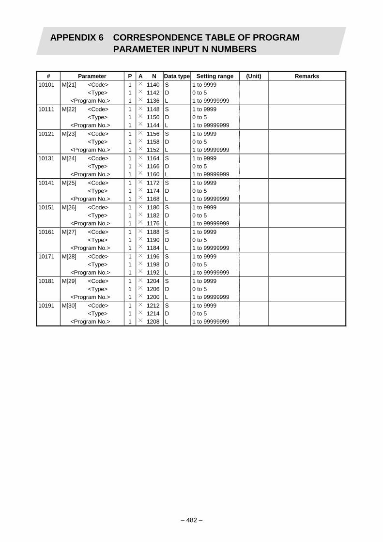
APPENDIX 6 CORRESPONDENCE TABLE OF PROGRAMPARAMETER INPUT N NUMBERS
– 482 –
# Parameter P A N Data type Setting range (Unit) Remarks
10101 M[21] <Code> <Type> <Program No.>
1 1 1
114011421136
S D L
1 to 9999 0 to 5 1 to 99999999
10111 M[22] <Code> <Type> <Program No.>
1 1 1
114811501144
S D L
1 to 9999 0 to 5 1 to 99999999
10121 M[23] <Code> <Type> <Program No.>
1 1 1
115611581152
S D L
1 to 9999 0 to 5 1 to 99999999
10131 M[24] <Code> <Type> <Program No.>
1 1 1
116411661160
S D L
1 to 9999 0 to 5 1 to 99999999
10141 M[25] <Code> <Type> <Program No.>
1 1 1
117211741168
S D L
1 to 9999 0 to 5 1 to 99999999
10151 M[26] <Code> <Type> <Program No.>
1 1 1
118011821176
S D L
1 to 9999 0 to 5 1 to 99999999
10161 M[27] <Code> <Type> <Program No.>
1 1 1
118811901184
S D L
1 to 9999 0 to 5 1 to 99999999
10171 M[28] <Code> <Type> <Program No.>
1 1 1
119611981192
S D L
1 to 9999 0 to 5 1 to 99999999
10181 M[29] <Code> <Type> <Program No.>
1 1 1
120412061200
S D L
1 to 9999 0 to 5 1 to 99999999
10191 M[30] <Code> <Type> <Program No.>
1 1 1
121212141208
S D L
1 to 9999 0 to 5 1 to 99999999

APPENDIX 6 CORRESPONDENCE TABLE OF PROGRAMPARAMETER INPUT N NUMBERS
– 483 –
# Parameter P A N Data type Setting range (Unit) Remarks
10201 M[31] <Code> <Type> <Program No.>
1 1 1
122012221216
S D L
1 to 9999 0 to 5 1 to 99999999
10211 M[32] <Code> <Type> <Program No.>
1 1 1
122812301224
S D L
1 to 9999 0 to 5 1 to 99999999
10221 M[33] <Code> <Type> <Program No.>
1 1 1
123612381232
S D L
1 to 9999 0 to 5 1 to 99999999
10231 M[34] <Code> <Type> <Program No.>
1 1 1
124412461240
S D L
1 to 9999 0 to 5 1 to 99999999
10241 M[35] <Code> <Type> <Program No.>
1 1 1
125212541248
S D L
1 to 9999 0 to 5 1 to 99999999
10251 M[36] <Code> <Type> <Program No.>
1 1 1
126012621256
S D L
1 to 9999 0 to 5 1 to 99999999
10261 M[37] <Code> <Type> <Program No.>
1 1 1
126812701264
S D L
1 to 9999 0 to 5 1 to 99999999
10271 M[38] <Code> <Type> <Program No.>
1 1 1
127612781272
S D L
1 to 9999 0 to 5 1 to 99999999
10281 M[39] <Code> <Type> <Program No.>
1 1 1
128412861280
S D L
1 to 9999 0 to 5 1 to 99999999
10291 M[40] <Code> <Type> <Program No.>
1 1 1
129212941288
S D L
1 to 9999 0 to 5 1 to 99999999

APPENDIX 6 CORRESPONDENCE TABLE OF PROGRAMPARAMETER INPUT N NUMBERS
– 484 –
6.2.12 Spindle NC parameter
# Parameter P A N Data type Setting range (Unit) Remarks 3001 slimt 1 21 784 L 0 to 99999 3002 2 21 788 L 0 to 99999 3003 3 21 792 L 0 to 99999 3004 4 21 796 L 0 to 99999 3005 smax 1 21 768 L 0 to 99999 3006 2 21 772 L 0 to 99999 3007 3 21 776 L 0 to 99999 3008 4 21 780 L 0 to 99999 3009 ssift 1 21 816 S 0 to 32767 3010 2 21 818 S 0 to 32767 3011 3 21 820 S 0 to 32767 3012 4 21 822 S 0 to 32767 3013 stap 1 21 800 L 0 to 99999 3014 2 21 804 L 0 to 99999 3015 3 21 808 L 0 to 99999 3016 4 21 812 L 0 to 99999 3017 stapt 1 21 824 S 1 to 5000 3018 2 21 826 S 1 to 5000 3019 3 21 828 S 1 to 5000 3020 4 21 830 S 1 to 5000 3021 sori 21 848 S 0 to 32767 3022 sgear 21 853 D 0 to 3 3023 smini 21 850 S 0 to 32767 3024 serr 21 854 D 0 to 99 3025 sname 21 855 D 0 to 9 3026 sprcmm 21 860 L 0 to 999999 3027 senc_pno 21 868 D 0 to 2 3028 sana_pno 21 866 D 0 to 2 3029 spflg 21 869 D 0 to FF (Hexadecimal number) 3030 senc_no 21 867 D 0 to FF (Hexadecimal number) 3031 sana_no 21 865 D 0 to FF (Hexadecimal number) 3032 smcp_no 21 857 D 0 to FF (Hexadecimal number)

APPENDIX 6 CORRESPONDENCE TABLE OF PROGRAMPARAMETER INPUT N NUMBERS
– 485 –
# Parameter P A N Data type Setting range (Unit) Remarks
3033 spt 21 858 S 0 to 9999 3034 sprlv 21 832 S 0 to 4095 3035 spplv 21 834 S 0 to 4095 3036 sptc1 21 836 L 0 to 99999 3037 sptc2 21 840 L 0 to 99999 3038 spdiv1 21 844 D 0 to 127 3039 spdiv2 21 845 D 0 to 127 3040 spplr 21 846 H0 0 to 1 3041 sppst 21 872 L 0 to 359999 1/1000° 0.000 to 359.999(°) 3042 GBsp 21 901 D 0 to 2 3043 sptc3 21 876 L 0 to 99999 0 to 99999(r/min) 3044 sptc4 21 880 L 0 to 99999 0 to 99999(r/min) 3045 sptc5 21 884 L 0 to 99999 0 to 99999(r/min) 3046 sptc6 21 888 L 0 to 99999 0 to 99999(r/min) 3047 sptc7 21 892 L 0 to 99999 0 to 99999(r/min) 3048 spdiv3 21 896 D 0 to 127 3049 spdiv4 21 897 D 0 to 127 3050 spdiv5 21 898 D 0 to 127 3051 spdiv6 21 899 D 0 to 127 3052 spdiv7 21 900 D 0 to 127
6.2.13 Spindle parameter
# Parameter P A N Data type Setting range (Unit) Remarks 3201 to 3584
SP001 to SP384
21 2n S Refer to Parameter Manual.
n: 0 to 383 (integer) n=#number – 3201
6.2.14 Spindle type servo parameter
# Parameter P A N Data type Setting range (Unit) Remarks 3601 to 3664
SV001 to SV064
21 1024+2n
S Refer to Parameter Manual.
n: 0 to 63 (integer) n=#number – 3601
(P number for M500L compatibility)
17 2n S Refer to Parameter Manual.
n: 0 to 63, 80 to 143, 160 to 223, 240 to 303, 320 to 383, 400 to 463 (integer) n=(#number – 3601) +(spindle number – 1)×80The spindle numbers correspond to <1> to <6> on the screen.

APPENDIX 6 CORRESPONDENCE TABLE OF PROGRAMPARAMETER INPUT N NUMBERS
– 486 –
6.2.15 PLC constant
# Parameter P A N Data type Setting range (Unit) Remarks 6301 to 6348
PLC constant 5 1 to 48
L ±99999999 N number=#number – 6300
6.2.16 PLC timer
# Parameter P A N Data type Setting range (Unit) Remarks 6000 to 6015
10ms add timer 6 0 to 15
S 0 to 32767 0.01s N number=#number – 6000
6016~ 6095
100ms add timer 6 16 to 95
S 0 to 32767 0.1s
6096~ 6103
100ms accumulating timer
6 96 to 103
S 0 to 32767 0.1s
6.2.17 PLC counter
# Parameter P A N Data type Setting range (Unit) Remarks 6200 to 6223
PLC constant 7 0 to 23
S 0 to 32767 N number=#number – 6200
6.2.18 Bit selection
# Parameter P A N Data type Setting range (Unit) Remarks 6401 to 6496
Bit selection 8 1 to 96
D
or H0 to 7
0 to FF (Hexadecimal number) 0 to 256 (Decimal number) 0 to 1
N number=#number – 6400 #6449 to 6496 are used by the machine manufacturer and Mitsubishi, so the contents are fixed.

APPENDIX 7 SUPPLEMENTARY DETAILS ON INCOMPLETETHREAD AREAS ARISING DURING THREAD CUTTING
– 487 –
APPENDIX 7 SUPPLEMENTARY DETAILS ON INCOMPLETE THREAD AREAS ARISING DURING THREAD CUTTING
Function and purpose
The delay caused by the automatic acceleration/deceleration and delay caused by the position loop in the servo system create an illegal pitch near the start and end points of thread cutting. When programming steps must be taken to assign thread cutting commands which include a margin for the approach distance δ1 and for the length of the area δ2 where the thread is incomplete during chamfering, as shown in the figure below.
Command direction
δ1 : Approach distance δ2 : Area where thread is incomplete during chamfering
Approach distance [ δ1 ]
(1) When Ts is not equal to zero:
Tp2e – – Ts2e – δ1 = t1 – (T (Ts + Tp – ) (mm) Where F : Thread cutting speed (mm/min)
Ts : Acceleration/deceleration time constant (s) Tp : Position loop time constant (s) t1 : Time taken until pitch error reaches allowable limit "a" (s)
If "p" is the pitch and "∆P" is the pitch error, then allowable limit "a" will be:
a = ( Tpe – – Tse – )
(2) When Ts is equal to zero
δ1 = t1 – ( Tp + Tpe ) (mm) a = e –
F 60
F60 Tp – Tp – Ts
t1Tp
t1Tp
1 Tp – Ts
t1 Tp
t1Ts
F 60
F 60
T1Tp
t1Tp

APPENDIX 7 SUPPLEMENTARY DETAILS ON INCOMPLETETHREAD AREAS ARISING DURING THREAD CUTTING
– 488 –
Since the calculation of approach distance δ1 is a complicated procedure, δ1 is normally determined from the chart on the next page. This chart is used as follows.
(a) Find the position on the p axis scale represents by the thread grade and pitch [P], and follow the perpendicular (1) drawn upward to find the point where it intersects with the curve of acceleration/deceleration time constant [Ts].
(b) Follow horizontal line (2) and find where it intersects with the thread cutting speed [F].
(c) Follow perpendicular (3) and find approach distance [δ1] on the scale at the point where it intersects with the δ1 axis.
(2)
(3) (1)
(Note 1) The chart on the next page applies when the position loop time constant Tp is 30ms.

APPENDIX 7 SUPPLEMENTARY DETAILS ON INCOMPLETETHREAD AREAS ARISING DURING THREAD CUTTING
– 489 –
Approach distance δ1 calculation chart
App
roac
h di
stan
ce [δ
1]
Met
erth
r ead
Uni
fy s
crew
thre
ad
Thre
ad n
umbe
r/inc
h
Thre
ad n
umbe
r/inc
h
JIS
cla
ss 1
JIS
cla
ss 2

APPENDIX 7 SUPPLEMENTARY DETAILS ON INCOMPLETETHREAD AREAS ARISING DURING THREAD CUTTING
– 490 –
Length of area where thread is incomplete during chamfering [δ2]
δ2 = (Ts + Tp) (mm) Where F : Thread cutting speed (mm/min) Ts : Acceleration/deceleration time constant (s) Tp : Position loop time constant (s) (Note 2) When proceeding with chamfering during a thread cutting cycle, the length of the
area where the thread is incomplete is equivalent to the value produced by adding δ2 determined by the above formula to the chamfering pitch set by parameter.
Leng
th o
f are
a w
here
thre
ad is
inco
mpl
ete
[ δ2
]
Thread cutting speed F
Chart to calculate length of area where thread is incomplete [ δ2 ]
F 60

APPENDIX 8 MACRO INTERFACE EXPANSION
– 491 –
APPENDIX 8 MACRO INTERFACE EXPANSION
Function and purpose
By using the macro interface input/output function, data can be input and output between the machining program and user PLC. The number of macro interface input/output points will be expanded as shown below when the macro interface expansion is used.
<Number of points for input> 128 points (of which, one-point read is 32 points) → 512 points (of which, one-point read is 160 points)
<Number of points for output> 128 points (of which, one-point write is 32 points) → 512 points (of which, one-point write is 160 points)
Refer to the tables on the following pages for the number of each point used for input/output.

APPENDIX 8 MACRO INTERFACE EXPANSION 8.1 Macro Interface Input
– 492 –
8.1 Macro Interface Input
Function and purpose
The macro interface input signals are used to find the user PLC status with the machining program. The machining program can read the details written into R72 to R79 and R1820 to R1843 with the user PLC using the variables #1000 to #1035, #1216 to #1227 and #1400 to #1527. Variables include those that read one point (1 bit) of the R register, and those that read two R registers (32 points). The variable value read with the R register one-point read variable can either be 1 or 0 (1 = contact closed/0 = contact open).
List of variables
<One-point read variables>
Variable number
Number of
points R register BIT Variable
numberNumber
of points
R register BIT Variable number
Number of
points R register BIT
# 1000 1 R 72 BIT 0 # 1400 1 R 1820 BIT 0 # 1432 1 R 1822 BIT 0# 1001 1 R 72 BIT 1 # 1401 1 R 1820 BIT 1 # 1433 1 R 1822 BIT 1# 1002 1 R 72 BIT 2 # 1402 1 R 1820 BIT 2 # 1434 1 R 1822 BIT 2# 1003 1 R 72 BIT 3 # 1403 1 R 1820 BIT 3 # 1435 1 R 1822 BIT 3# 1004 1 R 72 BIT 4 # 1404 1 R 1820 BIT 4 # 1436 1 R 1822 BIT 4# 1005 1 R 72 BIT 5 # 1405 1 R 1820 BIT 5 # 1437 1 R 1822 BIT 5# 1006 1 R 72 BIT 6 # 1406 1 R 1820 BIT 6 # 1438 1 R 1822 BIT 6# 1007 1 R 72 BIT 7 # 1407 1 R 1820 BIT 7 # 1439 1 R 1822 BIT 7# 1008 1 R 72 BIT 8 # 1408 1 R 1820 BIT 8 # 1440 1 R 1822 BIT 8# 1009 1 R 72 BIT 9 # 1409 1 R 1820 BIT 9 # 1441 1 R 1822 BIT 9# 1010 1 R 72 BIT A # 1410 1 R 1820 BIT A # 1442 1 R 1822 BIT A# 1011 1 R 72 BIT B # 1411 1 R 1820 BIT B # 1443 1 R 1822 BIT B# 1012 1 R 72 BIT C # 1412 1 R 1820 BIT C # 1444 1 R 1822 BIT C# 1013 1 R 72 BIT D # 1413 1 R 1820 BIT D # 1445 1 R 1822 BIT D# 1014 1 R 72 BIT E # 1414 1 R 1820 BIT E # 1446 1 R 1822 BIT E# 1015 1 R 72 BIT F # 1415 1 R 1820 BIT F # 1447 1 R 1822 BIT F# 1016 1 R 73 BIT 0 # 1416 1 R 1821 BIT 0 # 1448 1 R 1823 BIT 0# 1017 1 R 73 BIT 1 # 1417 1 R 1821 BIT 1 # 1449 1 R 1823 BIT 1# 1018 1 R 73 BIT 2 # 1418 1 R 1821 BIT 2 # 1450 1 R 1823 BIT 2# 1019 1 R 73 BIT 3 # 1419 1 R 1821 BIT 3 # 1451 1 R 1823 BIT 3# 1020 1 R 73 BIT 4 # 1420 1 R 1821 BIT 4 # 1452 1 R 1823 BIT 4# 1021 1 R 73 BIT 5 # 1421 1 R 1821 BIT 5 # 1453 1 R 1823 BIT 5# 1022 1 R 73 BIT 6 # 1422 1 R 1821 BIT 6 # 1454 1 R 1823 BIT 6# 1023 1 R 73 BIT 7 # 1423 1 R 1821 BIT 7 # 1455 1 R 1823 BIT 7# 1024 1 R 73 BIT 8 # 1424 1 R 1821 BIT 8 # 1456 1 R 1823 BIT 8# 1025 1 R 73 BIT 9 # 1425 1 R 1821 BIT 9 # 1457 1 R 1823 BIT 9# 1026 1 R 73 BIT A # 1426 1 R 1821 BIT A # 1458 1 R 1823 BIT A# 1027 1 R 73 BIT B # 1427 1 R 1821 BIT B # 1459 1 R 1823 BIT B# 1028 1 R 73 BIT C # 1428 1 R 1821 BIT C # 1460 1 R 1823 BIT C# 1029 1 R 73 BIT D # 1429 1 R 1821 BIT D # 1461 1 R 1823 BIT D# 1030 1 R 73 BIT E # 1430 1 R 1821 BIT E # 1462 1 R 1823 BIT E# 1031 1 R 73 BIT F # 1431 1 R 1821 BIT F # 1463 1 R 1823 BIT F

APPENDIX 8 MACRO INTERFACE EXPANSION 8.1 Macro Interface Input
– 493 –
Variable number
Number of
points R register BIT Variable
numberNumber
of points
R register BIT
# 1464 1 R 1824 BIT 0 # 1496 1 R 1826 BIT 0# 1465 1 R 1824 BIT 1 # 1497 1 R 1826 BIT 1# 1466 1 R 1824 BIT 2 # 1498 1 R 1826 BIT 2# 1467 1 R 1824 BIT 3 # 1499 1 R 1826 BIT 3# 1468 1 R 1824 BIT 4 # 1500 1 R 1826 BIT 4# 1469 1 R 1824 BIT 5 # 1501 1 R 1826 BIT 5# 1470 1 R 1824 BIT 6 # 1502 1 R 1826 BIT 6# 1471 1 R 1824 BIT 7 # 1503 1 R 1826 BIT 7# 1472 1 R 1824 BIT 8 # 1504 1 R 1826 BIT 8# 1473 1 R 1824 BIT 9 # 1505 1 R 1826 BIT 9# 1474 1 R 1824 BIT A # 1506 1 R 1826 BIT A# 1475 1 R 1824 BIT B # 1507 1 R 1826 BIT B# 1476 1 R 1824 BIT C # 1508 1 R 1826 BIT C# 1477 1 R 1824 BIT D # 1509 1 R 1826 BIT D# 1478 1 R 1824 BIT E # 1510 1 R 1826 BIT E# 1479 1 R 1824 BIT F # 1511 1 R 1826 BIT F# 1480 1 R 1825 BIT 0 # 1512 1 R 1827 BIT 0# 1481 1 R 1825 BIT 1 # 1513 1 R 1827 BIT 1# 1482 1 R 1825 BIT 2 # 1514 1 R 1827 BIT 2# 1483 1 R 1825 BIT 3 # 1515 1 R 1827 BIT 3# 1484 1 R 1825 BIT 4 # 1516 1 R 1827 BIT 4# 1485 1 R 1825 BIT 5 # 1517 1 R 1827 BIT 5# 1486 1 R 1825 BIT 6 # 1518 1 R 1827 BIT 6# 1487 1 R 1825 BIT 7 # 1519 1 R 1827 BIT 7# 1488 1 R 1825 BIT 8 # 1520 1 R 1827 BIT 8# 1489 1 R 1825 BIT 9 # 1521 1 R 1827 BIT 9# 1490 1 R 1825 BIT A # 1522 1 R 1827 BIT A# 1491 1 R 1825 BIT B # 1523 1 R 1827 BIT B# 1492 1 R 1825 BIT C # 1524 1 R 1827 BIT C# 1493 1 R 1825 BIT D # 1525 1 R 1827 BIT D# 1494 1 R 1825 BIT E # 1526 1 R 1827 BIT E# 1495 1 R 1825 BIT F # 1527 1 R 1827 BIT F
The expanded section is #1400 to #1527.
<32-point read variables>
Variable number
Number of
points R register Variable
number Number
of points
R register
# 1032 32 R 72/73 # 1220 32 R 1828/1829# 1033 32 R 74/75 # 1221 32 R 1830/1831# 1034 32 R 76/77 # 1222 32 R 1832/1833# 1035 32 R 78/79 # 1223 32 R 1834/1835# 1216 32 R 1820/1821 # 1224 32 R 1836/1837# 1217 32 R 1822/1823 # 1225 32 R 1838/1839# 1218 32 R 1824/1825 # 1226 32 R 1840/1841# 1219 32 R 1826/1827 # 1227 32 R 1842/1843
The expanded section is #1216 to #1227.

APPENDIX 8 MACRO INTERFACE EXPANSION 8.2 Macro Interface Output
– 494 –
8.2 Macro Interface Output
Function and purpose
The macro interface output signals are used to find the user macro status with the user pLC. The details written into #1100 to #1135, #1316 to #1327 and #1600 to #1727 with the machining program can be read with R172 to R179 and R1844 to R1867 R registers by the user PLC. Variables include those that write to one point (1 bit) of the R register, and those that write to two R registers (32 points). The variables and R registers used for macro interface output can also be used for macro interface input.
List of variables
<One-point write variables>
Variable number
Number of
points R register BIT Variable
numberNumber
of points
R register BIT Variable number
Number of
points R register BIT
# 1100 1 R 172 BIT 0 # 1600 1 R 1844 BIT 0 # 1632 1 R 1846 BIT 0# 1101 1 R 172 BIT 1 # 1601 1 R 1844 BIT 1 # 1633 1 R 1846 BIT 1# 1102 1 R 172 BIT 2 # 1602 1 R 1844 BIT 2 # 1634 1 R 1846 BIT 2# 1103 1 R 172 BIT 3 # 1603 1 R 1844 BIT 3 # 1635 1 R 1846 BIT 3# 1104 1 R 172 BIT 4 # 1604 1 R 1844 BIT 4 # 1636 1 R 1846 BIT 4# 1105 1 R 172 BIT 5 # 1605 1 R 1844 BIT 5 # 1637 1 R 1846 BIT 5# 1106 1 R 172 BIT 6 # 1606 1 R 1844 BIT 6 # 1638 1 R 1846 BIT 6# 1107 1 R 172 BIT 7 # 1607 1 R 1844 BIT 7 # 1639 1 R 1846 BIT 7# 1108 1 R 172 BIT 8 # 1608 1 R 1844 BIT 8 # 1640 1 R 1846 BIT 8# 1109 1 R 172 BIT 9 # 1609 1 R 1844 BIT 9 # 1641 1 R 1846 BIT 9# 1110 1 R 172 BIT A # 1610 1 R 1844 BIT A # 1642 1 R 1846 BIT A# 1111 1 R 172 BIT B # 1611 1 R 1844 BIT B # 1643 1 R 1846 BIT B# 1112 1 R 172 BIT C # 1612 1 R 1844 BIT C # 1644 1 R 1846 BIT C# 1113 1 R 172 BIT D # 1613 1 R 1844 BIT D # 1645 1 R 1846 BIT D# 1114 1 R 172 BIT E # 1614 1 R 1844 BIT E # 1646 1 R 1846 BIT E# 1115 1 R 172 BIT F # 1615 1 R 1844 BIT F # 1647 1 R 1846 BIT F# 1116 1 R 173 BIT 0 # 1616 1 R 1845 BIT 0 # 1648 1 R 1847 BIT 0# 1117 1 R 173 BIT 1 # 1617 1 R 1845 BIT 1 # 1649 1 R 1847 BIT 1# 1118 1 R 173 BIT 2 # 1618 1 R 1845 BIT 2 # 1650 1 R 1847 BIT 2# 1119 1 R 173 BIT 3 # 1619 1 R 1845 BIT 3 # 1651 1 R 1847 BIT 3# 1120 1 R 173 BIT 4 # 1620 1 R 1845 BIT 4 # 1652 1 R 1847 BIT 4# 1121 1 R 173 BIT 5 # 1621 1 R 1845 BIT 5 # 1653 1 R 1847 BIT 5# 1122 1 R 173 BIT 6 # 1622 1 R 1845 BIT 6 # 1654 1 R 1847 BIT 6# 1123 1 R 173 BIT 7 # 1623 1 R 1845 BIT 7 # 1655 1 R 1847 BIT 7# 1124 1 R 173 BIT 8 # 1624 1 R 1845 BIT 8 # 1656 1 R 1847 BIT 8# 1125 1 R 173 BIT 9 # 1625 1 R 1845 BIT 9 # 1657 1 R 1847 BIT 9# 1126 1 R 173 BIT A # 1626 1 R 1845 BIT A # 1658 1 R 1847 BIT A# 1127 1 R 173 BIT B # 1627 1 R 1845 BIT B # 1659 1 R 1847 BIT B# 1128 1 R 173 BIT C # 1628 1 R 1845 BIT C # 1660 1 R 1847 BIT C# 1129 1 R 173 BIT D # 1629 1 R 1845 BIT D # 1661 1 R 1847 BIT D# 1130 1 R 173 BIT E # 1630 1 R 1845 BIT E # 1662 1 R 1847 BIT E# 1131 1 R 173 BIT F # 1631 1 R 1845 BIT F # 1663 1 R 1847 BIT F

APPENDIX 8 MACRO INTERFACE EXPANSION 8.2 Macro Interface Output
– 495 –
<32-point write variables>
Variable number
Number of
points R register BIT Variable
numberNumber
of points
R register BIT
# 1664 1 R 1848 BIT 0 # 1696 1 R 1850 BIT 0# 1665 1 R 1848 BIT 1 # 1697 1 R 1850 BIT 1# 1666 1 R 1848 BIT 2 # 1698 1 R 1850 BIT 2# 1667 1 R 1848 BIT 3 # 1699 1 R 1850 BIT 3# 1668 1 R 1848 BIT 4 # 1700 1 R 1850 BIT 4# 1669 1 R 1848 BIT 5 # 1701 1 R 1850 BIT 5# 1670 1 R 1848 BIT 6 # 1702 1 R 1850 BIT 6# 1671 1 R 1848 BIT 7 # 1703 1 R 1850 BIT 7# 1672 1 R 1848 BIT 8 # 1704 1 R 1850 BIT 8# 1673 1 R 1848 BIT 9 # 1705 1 R 1850 BIT 9# 1674 1 R 1848 BIT A # 1706 1 R 1850 BIT A# 1675 1 R 1848 BIT B # 1707 1 R 1850 BIT B# 1676 1 R 1848 BIT C # 1708 1 R 1850 BIT C# 1677 1 R 1848 BIT D # 1709 1 R 1850 BIT D# 1678 1 R 1848 BIT E # 1710 1 R 1850 BIT E# 1679 1 R 1848 BIT F # 1711 1 R 1850 BIT F# 1680 1 R 1849 BIT 0 # 1712 1 R 1851 BIT 0# 1681 1 R 1849 BIT 1 # 1713 1 R 1851 BIT 1# 1682 1 R 1849 BIT 2 # 1714 1 R 1851 BIT 2# 1683 1 R 1849 BIT 3 # 1715 1 R 1851 BIT 3# 1684 1 R 1849 BIT 4 # 1716 1 R 1851 BIT 4# 1685 1 R 1849 BIT 5 # 1717 1 R 1851 BIT 5# 1686 1 R 1849 BIT 6 # 1718 1 R 1851 BIT 6# 1687 1 R 1849 BIT 7 # 1719 1 R 1851 BIT 7# 1688 1 R 1849 BIT 8 # 1720 1 R 1851 BIT 8# 1689 1 R 1849 BIT 9 # 1721 1 R 1851 BIT 9# 1690 1 R 1849 BIT A # 1722 1 R 1851 BIT A# 1691 1 R 1849 BIT B # 1723 1 R 1851 BIT B# 1692 1 R 1849 BIT C # 1724 1 R 1851 BIT C# 1693 1 R 1849 BIT D # 1725 1 R 1851 BIT D# 1694 1 R 1849 BIT E # 1726 1 R 1851 BIT E# 1695 1 R 1849 BIT F # 1727 1 R 1851 BIT F
The expanded section is #1600 to #1727.
<32-point write variables>
Variable number
Number of
points R register Variable
number Number
of points
R register
# 1132 32 R 172/173 # 1320 32 R 1852/1853# 1133 32 R 174/175 # 1321 32 R 1854/1855# 1134 32 R 176/177 # 1322 32 R 1856/1857# 1135 32 R 178/179 # 1323 32 R 1858/1859# 1316 32 R 1844/1845 # 1324 32 R 1860/1861# 1317 32 R 1846/1847 # 1325 32 R 1862/1863# 1318 32 R 1848/1849 # 1326 32 R 1864/1865# 1319 32 R 1850/1851 # 1327 32 R 1866/1867
The expanded section is #1316 to #1327.

APPENDIX 9 SYSTEM COMMON POSITION INFORMATIONRETRIEVING VARIABLES
– 496 –
APPENDIX 9 SYSTEM COMMON POSITION INFORMATION RETRIEVING VARIABLES
Function and purpose
The system common position information retrieving variables can read the machine coordinate values and workpiece coordinate values, etc., from any system.
(Example) To read system 3's 3rd axis machine coordinate value
System 1
|
#305023: Variable for reading system 3's 3rd axis machine coordinate value
System 2 System 3
1st axis – X1
2nd axis – Z1
3rd axis – Y1
4th axis – C1
1st axis – X2
2nd axis – Z2
3rd axis – C2
1st axis – X3
2nd axis – Z3
3rd axis – Y3
Machining program
#500=#305023;
|
|
#501=#305023;
|
|
#503=#305023;
|
System 1 System 2 System 3
Variable number
Each variable number is decided following the rules below.
#
: Axis number in each system
: Unique value
: System number
The last digit of the variable number corresponds to the control axis number. The head digit corresponds to the system number.

APPENDIX 9 SYSTEM COMMON POSITION INFORMATIONRETRIEVING VARIABLES
– 497 –
(1) Machine coordinate values System
Axis No.System 1 System 2 System 3 System 4 System 5 System 6 System 7 System 8
1 #105021 #205021 #305021 #405021 #505021 #605021 #705021 #8050212 #105022 #205022 #305022 #405022 #505022 #605022 #705022 #8050223 #105023 #205023 #305023 #405023 -- -- -- -- 4 #105024 #205024 #305024 #405024 -- -- -- -- 5 #105025 #205025 -- -- -- -- -- --
(2) Workpiece coordinate values
System Axis No.
System 1 System 2 System 3 System 4 System 5 System 6 System 7 System 81 #105041 #205041 #305041 #405041 #505041 #605041 #705041 #8050412 #105042 #205042 #305042 #405042 #505042 #605042 #705042 #8050423 #105043 #205043 #305043 #405043 -- -- -- -- 4 #105044 #205044 #305044 #405044 -- -- -- -- 5 #105045 #205045 -- -- -- -- -- --
(3) Tool offset amount
System Axis No.
System 1 System 2 System 3 System 4 System 5 System 6 System 7 System 81 #105081 #205081 #305081 #405081 #505081 #605081 #705081 #8050812 #105082 #205082 #305082 #405082 #505082 #605082 #705082 #8050823 #105083 #205083 #305083 #405083 -- -- -- -- 4 #105084 #205084 #305084 #405084 -- -- -- -- 5 #105085 #205085 -- -- -- -- -- --
Precautions and restrictions
(1) These variables read each data following the basic definition axis. (2) If an undefined axis is designated, the error "P241 No Variable No." will occur. (3) The coordinate values are read at the commanded timing. If the axis is moving, the
machine coordinate values and workpiece coordinate values during the movement will be read. Thus, depending on the conditions such as override, etc., and the system load state, the coordinate values read for each cycle may differ even within the same machining program.
(4) The tool offset amount is temporarily canceled during reference point return and machine coordinate system selection (G53). Thus, the read coordinate values may differ before and after machine coordinate system selection is executed. The coordinate values will also differ before and after workpiece coordinate system setting, local coordinate system setting, external workpiece coordinate system setting, coordinate system setting or tool offset (T function) is executed, so the coordinate values read out before and after the above function is executed will differ.
(5) If the axis coordinate values are read during mirror image, coordinate values read out and allowing for the mirror image must be used.
(6) Even if the inch command or metric command is executed in the machining program, the coordinate value will be read with the original unit system. (When initial inch is invalid, the metric system is applied, so even if inch is commanded with the machining program, the coordinate values will be read out with the metric system. When initial inch is valid, the inch system is applied, so even if metric is commanded with the machining program, the coordinate values will be read out with the inch system.)
(7) Data cannot be written into these variables. If written in, nothing will be executed, and the system will proceed to the next block.

APPENDIX 10 LIST OF ALARMS
– 498 –
APPENDIX 10 LIST OF ALARMS These alarms are generated during automatic operation. In the main, they denote errors in the creation of the machining programs and also program errors applying when programs matching the NC specifications have not been prepared.
Error No. Message Details Remedy
P10 No. of simultaneous axes over
• The number of axis addresses commanded in the same block is greater than the number provided for by the specifications.
• Divide the alarm block commands into two.
• Check the specifications.
P11 Illegal axis address
• The axis address names in the program commands and the axis address names set in the parameters do not match.
• Correct the axis names in the program.
P20 Division error • An axis has been commanded for which division cannot be made by the command units.
• Check the program.
P32 Illegal address • An address not contained in the specifications has been used.
• Check and correct the addresses in the program.
• Check the specifications. P33 Format error • The command format in the program
is not correct. • Check the program.
P34 Illegal G code • A G code not contained in the specifications has been commanded.
• Check and correct the G code addresses in the program.
P35 Setting value range over
• The setting range of the addresses has been exceeded.
• Check the program.
P36 Program end error
• "EOR" has been read during memory operation.
• Enter M02 or M30 at the end of the program.
• Enter M99 at the end of the subprogram.
P37 Prog. No. and sequence No. zero
• A zero has been designated for the program number or for the sequence number
• The program numbers which can be designated range from 1 to 99999999.
• The sequence numbers which can be designated range from 1 to 99999.
P38 No spec: Optional block skip
• A command with /2 to /9 has been issued.
• Check the program. (The command cannot be issued with /2 to /9.)
P39 No specifications
• The command issued is not included in the specifications.
• Check the specifications.
P50 No spec: Inch/mm
• A command for inch/millimeter conversion has been assigned using a G code though there is no such G code specification.
• Check the specifications.
P60 Compensation length over
• The commanded movement distance is too great (it exceeds 231).
• Check the value of each address in the program.

APPENDIX 10 LIST OF ALARMS
– 499 –
Error No. Message Details Remedy
P62 No F command • A cutting feedrate command or thread lead command has not been issued.
• When the power is turned ON, G01 is set as the movement modal command. Assign the feedrate using an F command.
• Designate F with a thread lead command.
P70 Arc radius error • The start and end points of the arc and the arc center are not correct.
• Check the address values designated for the program's start point, end point and the arc center.
• Check the plus and minus directions of the address value.
P71 Arc center error • The center of the arc is not found during R-designated circular interpolation.
• Check the address values in the program.
P72 No spec:
Herical cutting • A helical interpolation command was
issued though such specifications do not exist.
• Check the specifications. • Check the arc plane.
P73 P80 P90 No spec:
Thread cutting • A thread-cutting command has been
assigned though such specifications do not exist.
• Check the specifications.
P91 No spec: Vrbl lead thread (G34)
• A variable thread-cutting command has been issued though such specifications do not exist.
• Check the specifications.
P92 No spec: arc thread cutting
• The arc thread cutting command was issued though such specifications do not exist.
• Check the specifications.
P93 Illegal pitch value
• The thread lead (thread pitch) is not correct when thread cutting is commanded.
• Set the thread lead command properly in the thread cutting command.
P100 P110 P112 Plane selected
while R compen
• A plane selection command (G17, G18, G19) has been assigned during a tool radius compensation command and nose R compensa- tion command (G41, G42, G46).
• Assign the plane selection command after canceling the tool radius compensation command and nose R compensation command (by issuing the G40 command).
P113 Illegal plane select
• The circular command axis and selected plane do not match.
• Assign the circular command with the proper plane selection.
P120 No spec: Synchronous feed
• A synchronous feed command has been assigned though such specifications do not exist.
• Check the synchronous feed command specifications.
• Change the synchronous feed command (G95) into a per-minute feed command (G94). (The F command value must also be changed.)
P121

APPENDIX 10 LIST OF ALARMS
– 500 –
Error No. Message Details Remedy
P130 2nd M function code illegal
• The address specified by parameter is other than A, B or C.
• The name is duplicated with the axis name.
• Check the parameter’s 2nd miscellaneous function address.
• Designate an address different from the axis address.
P131 No spec: Cnst perphrl ctrl G96
• A constant surface speed command (G96) has been assigned even though such specifications do not exist.
• Check the specifications. • Change the constant surface speed
command (G96) into a speed command (G97).
P133 Illegal P-No.: G96
• An illegal constant surface speed control axis has been designated.
• An axis No. that does not exist in the command system was commanded during constant surface speed control.
• Check the parameter and program designation for the constant surface speed control axis.
P140 P141 P142 P150 No spec:
Nose R compensation
• The tool radius compensation and nose R compensation (G41, G42, G46) were issued even though the tool radius compensation and nose R compensation specifications are not provided.
• Check the tool radius compensation and nose R compensation specifications.
P151 Radius compen during arc mode
• A compensation command (G40, G41, G42, G46) has been assigned in the circular mode (G02, G03).
• Assign a rapid traverse command (G00) or linear command (G01) in the compensation command block or cancel block. (Set the modal to linear interpolation.)
P152 No intersection • The intersection point compensation vector is not found when a tool radius compensation or nose R compensa- tion command (G41, G42, G46) has been executed.
• Check the program.
P153 Compensation interference
• An interference error is occurred when a tool radius compensation and nose R compensation command (G41, G42, G46) is executed.
• Check the program.
P154 P155 Fixed cyc exec
during compen • A fixed cycle command was assigned
in the radius compensation mode. • The radius compensation mode is
established when a fixed cycle command is executed and so the radius compensation cancel command (G40) should be assigned.
P156 R compen direction not defined
• When the G46 nose R compensa- tion is started, the movement vector has an undefined compensation direction.
• Change to a movement vector whose compensation direction is defined.
• Change to a tool with a different tool nose point number.

APPENDIX 10 LIST OF ALARMS
– 501 –
Error No. Message Details Remedy
P157 R compen direction changed
• The compensation direction is reversed during G46 nose R compensation.
• Even if the compensation direction is reversed, change to a more suitable G command (G00, G28, G30, G33, G53).
• Change to a tool with a different tool nose point number.
• Set the G46 no reverse error parameter to ON.
P158 Illegal tip point • The tool nose point number is illegal (any number except 1 to 8) during G46 nose R compensation.
• Change to the correct tool nose point number.
P159 Cmnd invalid during R compen
• A command disable command has been issued in nose R compensation (G41, G42, or G46) mode.
• Cancel nose R compensation before the block where an error occurs.
P170 No offset number
• There is no compensation number (T ) command when a compensation command (G41, G42, G46) is assigned.
• The compensation number is greater than the number of sets in the specifications.
• Add the compensation number command to the compensation command block.
• Check the number of compensation number sets and correct the command so that it has a compensation number within the number of compensation sets.
P171 No spec: G10 option
• A G10 command has been assigned even though such specifications do not exist.
• Check the specifications.
P172 G10 L number error
• The L address command is not correct when the G10 command is assigned.
• Check the G10 command address L number and command the proper number.
P173 G10 P number error
• A compensation number outside the number of sets in the specifications has been assigned for the compensation number command when the G10 command is assigned.
• First check the number of compensation sets and then set the address P designation to within that number.
P180 No fixed cycle • A fixed cycle (G81 to G89) command has been assigned though such specifications do not exist.
• Check the specifications. • Correct the program.
P181 No spindle command (Tap cycle)
• The spindle speed command has not been assigned when a hole drilling fixed cycle command is assigned.
• Assign the spindle speed command (S) with the G84 or G88 hole drilling fixed cycle command.
P182 Synchronous tap error
• Connecting is not possible with the spindle unit.
• A synchronous tap command was issued for a system in the constant surface speed control.
• Check the connection with the spindle unit.
• Check whether the spindle encoder is present or not.
• Check the program. P183 No pitch/thread
number • The pitch or thread number
command is not present in the tap cycle of the hole drilling fixed cycle command.
• Assign the pitch or thread number command using the F or E command.

APPENDIX 10 LIST OF ALARMS
– 502 –
Error No. Message Details Remedy
P184 Pitch/thread number error
• An incorrect pitch or thread number command has been assigned in the tap cycle of the hole drilling fixed cycle command.
• Check the pitch or thread number.
P190 No spec: Cutting cycle
• A turning cycle command has been assigned though the turning cycle specifications are not provided.
• Check the specifications. • Delete the turning cycle command.
P191 Taper length error
• There is an error in the taper length command when the turning cycle command is assigned.
• Set the setting value of R in the turning cycle command to less than the movement amount of the axis.
P192 Chamfering error
• The chamfering conducted during the thread cutting cycle is illegal.
• Set a chamfering amount which does not protrude from the cycle.
P200 No spec: MRC cycle
• A compound fixed cycle command (G70 to G73) has been assigned even though the compound fixed cycle specifications are not provided.
• Check the specifications.
P201 Program error (MRC)
• One or more of the following commands are present in the subprogram which has been called by the compound fixed cycle:
1. Reference point return commands (G27, G28, G30), 2. Thread cutting (G33), 3. Fixed cycle, 4. Skip function (G31).
• The first movement block of the finish shape program in compound fixed cycle contains a circular command.
• Delete the following G codes from the subprogram which has been called by the compound fixed cycle (G70 to G76) : G27, G28, G30, G31. G33, G code in fixed cycle.
• Delete G2 and G3 from the first movement block of the finish shape program in compound fixed cycle.
P202 Block over (MRC)
• The number of blocks in the shape program which has been called by the compound fixed cycle exceeds 50.
• Make the number of blocks in the shape program which has been called by the compound fixed cycle (G70 to G73) less than 50.
P203 D cmnd figure error (MRC)
• The shape program of the compound fixed cycle (G70 to G73) does not give the shape which can be cut properly.
• Check the shape program in the compound fixed cycle (G70 to G73).
P204 E cmnd fixed cycle error (MRC)
• The command value in the compound fixed cycle (G70 to G76) is not correct.
• Check the command value in the compound fixed cycle (G70 to G76).
P210 No spec: Pattern cycle
• A compound fixed cycle command has been assigned though the compound fixed cycle (G74 to G76) specifications are not provided.
• Check the specifications.
P230 Sub-program nesting over
• The number of times subprograms have been called in sequence from subprograms has exceeded 8.
• Check the number of subprogram calls and correct the program so that it does not exceed 8.

APPENDIX 10 LIST OF ALARMS
– 503 –
Error No. Message Details Remedy
P231 No sequence No.
• The sequence number commanded by GOTO has not been set when calling out a subprogram or when returning to the main program from a subprogram.
• Enter the sequence number in the appropriate block.
P232 No program No.
• The subprogram has not been registered when it is called.
• Register the subprogram.
P240 No spec: Variable command
• A variable command has been assigned though such specifications (# ) do not exist.
• Check the specifications. • Delete the variable command.
P241 No variable No. • The commanded variable number is higher than the variable numbers in the specifications.
• Check the specifications. • Check the program variable
numbers. P242 " = " not defined
at vrble set • " = " has not been commanded when
a variable is defined. • Set " = " into the program variable
definition. P243 Can't use
variables • Even though the hypothetical
coordinates were set, the basic coordinate system position information was read during end point synchronization.
• Review the program.
P250 P251 P252 P260 P270 No spec:
User macro • A macro specification command has
been assigned though such specifications do not exist.
• Check the specifications. • Delete the macro command.
P271 No spec: Macro interrupt
• A macro interrupt command has been issued though it is not included in the specifications.
• Check the specifications.
P272 NC and macro texts in a block
• An NC statement and a macro statement exist in the same block.
• Check the program, and program so that the NC statement and macro statement are in separate blocks.
P273 Macro call nesting over
• The maximum number of macro call nesting levels have been exceeded.
• Check the program and correct so that the macro calls do not exceed the number of levels provided for by the specifications.
P275 Macro argument over
• There are too many argument sets in macro call argument type II.
• Check the program.
P276 Illegal G67 command
• A G67 command has been assigned though it is not during the G66 command modal.
• Check the program. • The G67 command serves to cancel
the call and so the G66 command is assigned before this command.
P277 Macro alarm message
• An alarm command has been issued in user macro.
• Check the user macro program.
P280 Brackets [ ] nesting over
• More than 5 bracket " [ " or " ] " parentheses have been used in a block.
• Check the program and correct so that the number of " [ " or " ] " parentheses does not exceed 5 brackets.

APPENDIX 10 LIST OF ALARMS
– 504 –
Error No. Message Details Remedy
P281 Brackets [ ] not paired
• The number of the " [ " or " ] " parentheses commanded in a block does not match.
• Check the program and correct so that the numbers of " [ " and " ] " parentheses are paired off properly.
P282 Calculation impossible
• An operation formula is not correct. • Check the program and correct the operation formula.
P283 Divided by zero • The division denominator is zero. • Check the program and correct so that the denominator for division in the operation formula is not zero.
P284 Integer value overflow
• In the process of operation the integer value has exceeded –231 (231–1).
• Check the operation formula in the program and correct so that the value of the integers after the operation does not exceed –231.
P285 Float value overflow
• There is a variable data overflow. • Check the variable data in the program.
P290 IF sentence error
• There is an error in the IF [<conditional formula>] GOTO statement.
• Check the program.
P291 WHILE sentence error
• There is an error in the WHILE [< conditional formula>] DO to END statement.
• Check the program.
P292 SETVN sentence error
• The variable name setting or SETVN statement is incorrect.
• Check the program. • Make sure that the variable name of
the SETVN statement has 7 or fewer characters.
P293 DO-END nesting over
• The numbers of ’s in the DO and END of the WHILE [<conditional formula>] DO to END statement (nesting levels) has been exceeded 27.
• Check the program and correct so that the nesting levels of DO to END statements does not exceed 27.
P294 DO and END not paired
• The DO and END are not paired off properly.
• Check the program and correct so that the DO and END are paired off properly.
P300 Variable name illegal
• A variable name has not been commanded properly.
• Correct the program so that the variable name is correct.
• Check the variable names in the program and correct them.
P301 Variable name duplicated
• A variable name has been duplicated.
• Correct the program so that the variable names are not duplicated.
P340 Coordinate parameter illegal
• Even though there is a tool offset amount, the coordinate system setting command (G92) was issued immediately after the double-turret mirror image mode change command was issued.
• Review the machining program. • Turn the setup parameter #8053
CONTROL BIT6 ON.
P370 No spec: Mirr image dubl turet
• An opposite tool rest mirror image command (G68) has been assigned though the double-turret mirror image specifications are not provided.
• Check the specifications.

APPENDIX 10 LIST OF ALARMS
– 505 –
Error No. Message Details Remedy
P380 No spec: Corner R/C
• A corner chamfering (C) or corner rounding (R) command has been assigned though the corner chamfering and corner rounding I and II specifications do not exist.
• Check the specifications. • Remove "corner R" and "corner C"
from the program.
P381 No spec: Arc R/C
• A corner chamfering (C) or corner rounding (R) command has been assigned in a circular interpolation block though the corner chamfering and corner rounding II specifications do not exist.
• Check the specifications.
P382 No corner movement
• There is no movement command in the block following the corner chamfering/rounding.
• Assign the block following the corner R/C command in the block with movement.
P383 Corner movement short
• The movement distance is shorter than the corner R/C command when such a command is assigned.
• Since the movement distance is shorter than the corner R/C, the corner R/C should be reduced to less than the movement distance.
P384 Corner next movement short
• With a corner R/C command, the movement distance in the following block is shorter than the corner R/C.
• Since the movement distance in the following block is shorter than the corner R/C, the corner R/C should be made less than the movement distance.
P385 Corner during G0/G33
• G0 or G33 is contained in the block following the corner R/C.
• Check the program.
P390 No spec: Geometric
• A geometric command has been issued while geometric I is not included in the specifications.
• Check the specifications.
P391 No spec: Geometric arc
• A geometric command has been issued while geometric II is not included in the specifications.
• Check the specifications.
P392 Angle<1 degree (GEOMT)
• The difference in the angle between geometric lines is less than 1 degree.
• Correct the geometric angle.
P393 Inc value in 2nd block (GEOMT)
• The commands in the second geometric block have been assigned as incremental values.
• Assign the commands in the second geometric block as absolute values.
P394 No linear move command (GEOMT)
• There is no linear command in the second geometric block.
• Assign the linear command (G01) in the second block.
P395 Illegal address (GEOMT)
• The geometric format is incorrect. • Check the program.
P396 Plane selected in GEOMT ctrl
• A plane selection command was assigned in the geometric command.
• Select the plane before issuing the geometric command.
P397 Arc error (GEOMT)
• The arc end point did not contact or intersect with the next block's start point during geometric IB, II.
• Check the previous and next commands including the geometric arc command.
P398 No spec: Geometric 1B
• The geometric command was issued when the geometric IB specifications were not available.
• Check the specifications.

APPENDIX 10 LIST OF ALARMS
– 506 –
Error No. Message Details Remedy
P399 Direction error (GEOMT)
• The monotone is not incremented or decremented in geometric II.
• Check the program so that the monotone is incremented or decremented.
P410 No spec: Address convertor
• The specifications for converting absolute/incremental axis addresses do not exist.
• Check the specifications.
P420 No spec: Parameter input
• A parameter input command has been assigned though such specifications do not exist.
• Check the specifications.
P421 Parameter input error
• The commanded parameter number and setting data is illegal.
• An illegal G command address has been assigned in the parameter input mode.
• A parameter input command has been assigned during a fixed cycle modal or nose R compensation.
• Check the program.
P430 Zero return not completed
• A movement command except reference point return has been assigned for an axis which has not returned to the reference point.
• Execute the reference point return manually.
P431 No spec: 2, 3, 4th ref-point ret
• A 2nd, 3rd or 4th reference point return command has been assigned though such specifications do not exist.
• Check the specifications.
P432 No spec: G29 • A start position return command (G29) has been assigned though such specifications do not exist.
• Check the specifications.
P433 No spec: G27 • A zero point check command (G27) has been assigned though such specifications do not exist.
• Check the specifications.
P434 Compare error • There is an axis which does not return to the zero point position when the zero point check command (G27) is executed.
• Check the program.
P435 G27 and M commands in a block
• An M independent command has been assigned simultaneously in the G27 command block.
• An M independent command cannot be assigned in the G27 command block and so the G27 command and M independent command should be divided into separate blocks.
P436 G29 and M commands in a block
• An M independent command has been assigned simultaneously in the G29 command block.
• An M independent command cannot be assigned in the G29 command block and so the G29 command and M independent command should be divided into separate blocks.
P450 No spec: Chuck barrier
• A chuck barrier valid command (G22) has been assigned though the chuck barrier specifications are not provided.
• Check the specifications.
P459 External I/O timeout
• A timeout error occurred in the external input/output device.
• Check the external input/output device.
• Check the timeout time parameter.

APPENDIX 10 LIST OF ALARMS
– 507 –
Error No. Message Details Remedy
P460 Tape I/O error • An error has occurred in the tape reader or in the printer during macro printing.
• Check the power and cables for the connected units.
• Check the Input/output parameters. P461 No file data • The machining program file cannot
be read or the file cannot be found. • Review the machining program. • The program saved in the memory
may be damaged. Output all of the necessary data, such as the machining programs, tool data and workpiece offset data, to an external device, and then format.
P462 Computer link error
• A communication error occurred in the computer link.
• Reset the system.
P480 No spec: Milling • No milling function specifications are found.
• Check the specifications.
P481 Illegal G code (mill)
• An invalid G code was commanded in the milling mode.
• Remove the illegal G command.
P482 Illegal axis (mill)
• A rotation axis command was issued in the milling mode.
• Alternatively, milling was performed though an illegal value was set for the milling axis number.
• Delete the rotation axis command. • Check the milling axis number.
P483 Cancel shift X (mill)
• The milling mode was turned ON before the tool offset operation was completed or in the offset temporary cancel state.
• Review the program. • Complete tool offset before entering
the milling mode.
P484 ZRN not completed (mill)
• A movement command was issued in milling mode to the axis that had not completed return to the reference point.
• Manually return the axis to the reference point.
P485 Illegal modal (mill)
• The system entered in milling mode during nose R compensation or constant surface speed control.
• A T command was issued in milling mode.
• The milling mode was changed to the turning mode during tool radius compensation.
• Before issuing G12.1, issue G40 (nose R compensation cancel) or G97 (constant surface speed cancel).
• Before issuing G12.1, issue a T command.
• Before issuing G13.1, issue G40 (tool radius compensation cancel).
P500 No spec: Cross machining (G110)
• A cross machining command (G110) was issued though it was not included in the specifications.
• Check the specifications.
P501 Cross (G110) impossible
• A cross machining command (G110) was issued in nose R, milling, balance cut, fixed cycle, or double-turret mirror image mode.
• Check the program.
P502 Illegal G110 $No.
• An illegal axis system number was commanded.
• Correct the program address.

APPENDIX 10 LIST OF ALARMS
– 508 –
Error No. Message Details Remedy
P503 Illegal G110 axis
• The commanded axis was not found. • Too many axes were commanded. • The commanded axis cannot be
controlled by the commanded system.
• Correct the program address.
P510 Illegal G128/G129 axis
• During the axis movement synchronous superimposition command (G128, G129), the synchronous superimposing axis is not between the start position and the end position of synchronous superimposition.
• A rotation axis was commanded for the synchronous superimposing axis or master axis.
• Check the program.
P511 Illegal $-command
• The axis movement synchronous superimposition command (G128, G129) was issued in a system that does not contain a synchronous superimposing axis.
• Check the program.
P520 No TGSET value
• A position control command (G132) or position control variable skip command (G133) was issued before a set number specification (TGSET[ ]) command.
• Check the program.
P521 Illegal G code (G130)
• One of G130 to G133 was issued during nose R compensation (G41, G42, or G46), thread cutting (G33), fixed cycle (G70 to G79, or G81 to G89), or milling (G12.1) modal.
• Check the program.
P600 No spec: Auto TLM
• An automatic tool length measurement command (G37) has been assigned through such specifications do not exist.
• Check the specifications.
P601 No spec: Skip • A skip command (G31/G160) has been assigned though such specifications do not exist.
• Check the specifications.
P602 No spec: Multi skip
• A multiple skip command (G31.1, G31.2, G31.3) was assigned though no such command exists in the specifications.
• Check the specifications.
P603 Skip speed 0 • The skip speed is zero. • Command the skip speed. P604 G37 illegal axis • The axis has not been commanded in
the automatic tool length measurement block or, alternatively, two or more axes have been commanded.
• Command only one axis.
P605 H and G37 commands in a block
• The T code is in the same block as the automatic tool length measurement command.
• Assign the T command before the block which contains the automatic tool length measurement command.

APPENDIX 10 LIST OF ALARMS
– 509 –
Error No. Message Details Remedy
P606 H command not found before G37
• The T code has still not been commanded for automatic tool length measurement.
• Assign the T command before the block which contains the automatic tool length measurement command.
P607 Signal turned illegally by G37
• The measurement position arrival signal has been set ON before the area commanded by the parameter deceleration area "d" or D command.
• Alternatively, the signal was not set ON until the end.
• Check the program.
P608 Skip during radius compen
• The skip command was assigned during a radius compensation or nose R compensation command.
• Assign the radius compensation cancel or nose R compensation cancel command (G40) or remove the skip command.
P609 Illegal skip axis • An axis was not commanded in the G160 block, or two or more axes were commanded.
• Command only one axis.
P700 No B, N number
• When using the end point synchronization function, the designated block's identification number was not found at the end point block.
• Check the program.
P710 Inclined ax ctrl mode illegal
• The G170/G171 command was issued in the milling mode, nose R mode, mirror image, compound fixed cycle or constant surface speed control mode.
• Check the program.
P711 Coordinate conver prohibited
• The hypothetical coordinate setting was commanded in a mode in which the hypothetical coordinates cannot be set.
• Inclined coordinate rotation was commanded in a mode in which the inclined coordinate rotation cannot be commanded.
The hypothetical coordinate setting and the hypothetical coordinate cancel command were executed in the following modes. Cancel the mode. • Mirror image is applied on the
imaginary coordinate target axis. • The fixed cycle mode is active. • The milling mode is active. • The nose R compensation mode is
active. The inclined coordinate rotation command and inclined coordinate rotation cancel command were executed in the following modes. Cancel the mode. • Mirror image is applied on the
inclined coordinate rotation target axis.
• The fixed cycle mode is active. • The milling mode is active. • The nose R compensation mode is
active.

APPENDIX 10 LIST OF ALARMS
– 510 –
Error No. Message Details Remedy
P712 Invalid axis of coord conver
• An illegal G code was commanded during hypothetical coordinate setting.
• An illegal command was issued during the inclined coordinate rotation mode.
One of the following commands was executed during the hypothetical coordinate setting. • Automatic reference point return
(G28/G29) • 2nd, 3rd, 4th reference point return
(G30) • Reference point check (G27) • Random axis exchange (G140) A command that changes the hypothetical coordinate target axis to a non-control axis was executed. • Current value sampling (G159) • Torque skip (G160) • Collision detection (G161) One of the following commands was executed during the inclined coordinate rotation mode. • Milling command (G12.1) • Thread cutting command • Hobbing command • Automatic reference point return
(G28/G29) • 2nd, 3rd, 4th reference point return
(G30) • Reference point check (G27) • Tool position return command • Mirror image command • Compound type turning cycle (G70 to
G76) • Skip command (G31) • Random axis exchange (G140) A command that changes the inclined coordinate rotation target axis to a non-control axis was executed. • Current value sampling (G159) • Torque skip (G160) • Collision detection (G161)
P718 TDO illegal startup
• An arc command was issued for the tool axis direction tool length offset startup command.
• An arc command was issued for the tool axis direction tool length offset startup command. Change the arc command to a linear command.
P719 TDO ctrl axis illegal
• An illegal value was set for the tool axis direction tool length offset target axis.
• Check the plane selection parameters #8001 (I axis) and #8003 (K axis).
• Confirm that the tool axis direction tool length offset parameter #1182 (bt_axname) is a rotary axis.

APPENDIX 10 LIST OF ALARMS
– 511 –
Error No. Message Details Remedy
P720 TDO command prohibited
• Tool axis direction tool length offset was commanded in an illegal mode.
The tool axis direction tool length offset start command or cancel command was executed in one of the following modes. Cancel the mode. • Mirror image is applied on the tool
axis direction tool length offset target axis.
• The milling mode is active. • The nose R compensation mode is
active. • The thread cutting mode is active. • The end point synchronization mode
is active. • The tool axis direction tool length
offset mode is active. • The tool offset amount is not
commanded. Command G174 after the tool offset command (T command).
• The tool-spindle synchronization II (hobbing) mode is active.
P721 Illegal command in TDO mode
• An illegal command was executed during the tool axis direction tool length offset modal.
One of the following commands was executed during the tool axis direction tool length offset modal. • Milling command (G12.1) • Thread cutting command • Automatic reference point return
command (G28/G29) • 2nd, 3rd, 4th reference point return
command (G30) • Reference point check command
(G27) • Mirror image command • Compound type turning cycle (G70 to
G76) • Skip command (G31) • Inclined coordinate rotation
command (G173) • Automatic tool length measurement
(G37) • Double-turret mirror image
command • T command double-turret mirror
image command • Tool-spindle synchronization II
(hobbing) command P980 Illegal
HSPRGM call • During subprogram call involving
nesting, the execution format data machine maker macro and EIA machine maker macro were called out alternately.
• Review the machine maker macros.

APPENDIX 10 LIST OF ALARMS
– 512 –
Error No. Message Details Remedy
P981 Illegal HSPRGM program
• A G code incompatible with execution type data was commanded.
• The return destination sequence No. was commanded with the program return command M99 called out from the execution type data.
• Execution type data was executed when the G code series was set to a value other than 1.
• Review the machine maker macros. • Review the G code series setting.
(The execution type data can be used only with the G code series 1.)
P982 HSPRGM conversion incomplete
• The machine maker macro conversion process has not been completed.
• Start the EIA → execution type data conversion process.
P990 PREPRO error • Combining commands that required pre-reading (nose R compensation, corner chamfering/corner rounding (R), geometric I, geometric IB, and compound fixed cycle commands) resulted in eight or more pre-read blocks.
• Reduce the number of commands that require pre-reading or delete such commands.

Revision History
Date of revision Manual No. Revision details
Oct. 2000 BNP-B2232A First edition created.
Jan. 2004 BNP-B2232C (1) The following explanations were added. • Circular thread cutting • Synchronous tapping cycle; return override, spindle zero point return method • System variables: #5081 to 5083 tool compensation amount • Axis name change • Inclined coordinate rotation control • G0/G53 speed designated positioning • Tool-spindle synchronization I, II E command range expansion (10 to 999)
(2) Other mistakes were corrected.

Notice
Every effort has been made to keep up with software and hardware revisions in the contents described in this manual. However, please understand that in some unavoidable cases simultaneous revision is not possible. Please contact your Mitsubishi Electric dealer with any questions or comments regarding the use of this product.
Duplication Prohibited This instruction manual may not be reproduced in any form, in part or in whole, without written permission from Mitsubishi Electric Corporation.
© 2000-2004 MITSUBISHI ELECTRIC CORPORATION ALL RIGHTS RESERVED.

BNP-B2232C(ENG)
M600L Series
008-021
(0401)MEE
Specifications subject to change without notice.Printed in Japan on recycled paper.
MITSUBISHI ELECTRIC CORPORATION HEAD OFFICE : MITSUBISHI DENKI BLDG., 2-2-3, MARUNOUCHI, CHIYODA-KU, TOKYO 100-8310, JAPAN
MODEL
Manual No.
MODELCODE