Embed Size (px)
Citation preview

CN361 Microprocessor Systems DesignAssembly Language (AVR)
Nawin Somyat
Department of Electrical and Computer EngineeringThammasat University

Outline
Course Contents1 Introduction2 Simple Computer3 Micro Architecture4 Peripherals5 Applications
Outline1 Assembly Language
Source FileDirectivesInstructions
CN361 Microprocessor Systems Design 2 / 38

Assembly Language
An assembly language is essentially a mapping of mnemonics tomachine code.
specific to processor (processor/machine dependent).use an assembler to translate assembly source code intomachine code.each assembly language is also specific to an assembler(different assemblers for the same processor).usually consists of
mnemonics (normal instructions)directives (pseudo instructions)expressions (operands, operators)additional features e.g. macro
CN361 Microprocessor Systems Design 3 / 38

Assembly Language Soure File
For AVR assembler:An input line may take one of the four following forms:1. [label:] directive [operands] [Comment]2. [label:] instruction [operands] [Comment]3. Comment4. Empty line
A comment has the following form:; [Text]
case-insensitiveitems in brackets are optional.text after ‘;’ until the end of line (EOL) is ignored.AVR Assembler 2 also supports C-style comment
// - line comment/**/ - group comment
CN361 Microprocessor Systems Design 4 / 38

Example: AVR Assembly Source File
Example: AVR Assembly code
.NOLIST
.INCLUDE "m168Adef.inc" ; definition for ATMega168A
.LIST
.DEF sw = R1
.DEF led = R2
.CSEG ; put following code in code memory (flash)rjmp main
.ORG 0x0012 ; start this code at address 0x0012jmp TIM2_OVF ; Timer2 Overflow Handler
.ORG 0x0042 ; start this code at address 0x0042main:mloop:
in sw, PIND ; read port Dmov led, sw ; copy to ledout PORTD, led ; output to port Drjmp mloop
TIM2_OVF_vect: ; Timer2 interrupt handlerreti ; do nothing
CN361 Microprocessor Systems Design 5 / 38

Labels
symbolic name to identify location of code in a programnormally start with letter and followed by one or more lettersand digits, then colon (‘;’).use sensible name as normally used as identifiers in anyhigh-level language, i.e. indicate its purpose or function.
Example: Labels
table_a: ; define table a...
main: ; main code...
read_sw: ; read from switch(es)...
disp_led: ; code to display to led(s)...
algo_1: ; compute algorithm 1...
algo_2: ; compute algorithm 2...
CN361 Microprocessor Systems Design 6 / 38

Directives
Used to adjust program location in memory, define macros,initialize memory etc. All directives must be preceded by a period.
Directive Description
BYTE Reserve byte to a variableCSEG Code SegmentDB Define constant byte(s)DEF Define a symbolic name on a registerDEVICE Define which device to assemble forDSEG Data SegmentDW Define constant word(s)ENDMACRO End macroEQU Set a symbol equal to an expressionESEG EEPROM SegmentEXIT Exit from fileINCLUDE Read source from another fileLIST Turn listfile generation onLISTMAC Turn macro expansion onMACRO Begin macroNOLIST Turn listfile generation offORG Set program originSET Set a symbol to an expression
CN361 Microprocessor Systems Design 7 / 38

Directive: LIST, NOLISTLIST - Turn the listfile generation onNOLIST - Turn the listfile generation offThe LIST directive tells the Assembler to turn listfile generation on. TheAssembler generates a listfile which is a combination of assembly source code,addresses and opcodes. Listfile generation is turned on by default. Thedirective can also be used together with the NOLIST directive in order to onlygenerate listfile of selected parts of an assembly source file.
Syntax:.LIST
.NOLIST
Example: LIST, NOLIST
.NOLIST ; Disable listfile generation
.INCLUDE "macro.inc" ; The included files will not
.INCLUDE "const.def" ; be shown in the listfile
.LIST ; Reenable listfile generation
CN361 Microprocessor Systems Design 8 / 38

Directive: INCLUDE
INCLUDE - Include another fileThe INCLUDE directive tells the Assembler to start reading from a specifiedfile. The Assembler then assembles the specified file until end of file (EOF) oran EXIT directive is encountered. An included file may itself contain INCLUDEdirectives.
Syntax:.INCLUDE "filename"
Example: INCLUDE
; iodefs.asm:.EQU sreg = 0x3f ; Status register.EQU sphigh = 0x3e ; Stack pointer high.EQU splow = 0x3d ; Stack pointer low
; incdemo.asm.INCLUDE "iodefs.asm" ; Include I/O definitions
in r0,sreg ; Read status register
CN361 Microprocessor Systems Design 9 / 38

Directive: EQU
EQU - Set a symbol equal to an expressionThe EQU directive assigns a value to a label. This label can then be used inlater expressions. A label assigned to a value by the EQU directive is aconstant and can not be changed or redefined.
Syntax:.EQU labelname = expression
Example: EQU
.EQU io_offset = 0x23
.EQU porta = io_offset + 2
.CSEG ; Start code segmentclr r2 ; Clear register 2out porta,r2 ; Write to Port A
CN361 Microprocessor Systems Design 10 / 38

Directive: SET
SET - Set a symbol equal to an expressionThe SET directive assigns a value to a label. This label can then be used inlater expressions. Unlike the .EQU directive, a label assigned to a value by theSET directive can be changed (redefined) later in the program.
Syntax:.SET labelname = expression
Example: SET
.SET FOO = 0x114 ; set FOO to point to an SRAM locationlds r0, FOO ; load location into r0
.SET FOO = FOO + 1 ; increment (redefine) FOO. This'd be illegal if using .EQUlds r1, FOO ; load next location into r1
CN361 Microprocessor Systems Design 11 / 38

Directive: DEF
DEF - Set a symbolic name on a registerThe DEF directive allows the registers to be referred to through symbols. Adefined symbol can be used in the rest of the program to refer to the register itis assigned to. A register can have several symbolic names attached to it. Asymbol can be redefined later in the program.
Syntax:.DEF Symbol = Register
Example: DEF
.DEF temp = R16
.DEF ior = R0
.CSEGldi temp,0xf0 ; Load 0xf0 into temp registerin ior,0x3f ; Read SREG into ior registereor temp,ior ; Exclusive or temp and ior
CN361 Microprocessor Systems Design 12 / 38

Memory Segments
Different types of memory are known as segments to theassembler.Some directives allow code/data to be placed into differentsegments.
AVR provides 3 segments:Code segment (Flash)
can place code or constant data hereData segment (SRAM)
cannot place data here, just reserve space (for variables)EEPROM segment
can place constants here
CN361 Microprocessor Systems Design 13 / 38

Directive: BYTEBYTE - Reserve bytes to a variableThe BYTE directive reserves memory resources in the SRAM or EEPROM. Inorder to be able to refer to the reserved location, the BYTE directive should bepreceded by a label. The directive takes one parameter, which is the number ofbytes to reserve. The directive can not be used within a Code segment. Notethat a parameter must be given. The allocated bytes are not initialized.
Syntax:labelname: .BYTE expression
Example: BYTE
.DSEGvar1: .BYTE 1 ; reserve 1 byte to var1table: .BYTE tab_size ; reserve tab_size bytes
.CSEGldi r30,low(var1) ; Load Z register lowldi r31,high(var1) ; Load Z register highld r1,Z ; Load VAR1 into register 1
CN361 Microprocessor Systems Design 14 / 38

Directive: DBDB - Define constant byte(s) in program memory and EEPROMThe DB directive reserves memory resources in the program memory or theEEPROM memory. In order to be able to refer to the reserved locations, theDB directive should be preceded by a label. The DB directive takes a list ofexpressions, and must contain at least one expression. The DB directive mustbe placed in a Code Segment or an EEPROM Segment.The expression list is a sequence of expressions, delimited by commas. Eachexpression must evaluate to a number between -128 and 255. If the expressionevaluates to a negative number, the 8 bits twos complement of the number willbe placed in the program memory or EEPROM memory location.
Syntax:labelname: .DB expressionlist
Example: DB
.CSEGconsts: .DB 0, 255, 0b01010101, -128, 0xaa.ESEGconst2: .DB 1,2,3
CN361 Microprocessor Systems Design 15 / 38

Directive: DWDW - Define constant word(s) in program memory and EEPROMThe DW directive reserves memory resources in the program memory or theEEPROM memory. In order to be able to refer to the reserved locations, theDW directive should be preceded by a label. The DW directive takes a list ofexpressions, and must contain at least one expression. The DW directive mustbe placed in a Code Segment or an EEPROM Segment.The expression list is a sequence of expressions, delimited by commas. Eachexpression must evaluate to a number between -32768 and 65535. If theexpression evaluates to a negative number, the 16 bits two’s complement of thenumber will be placed in the program memory or EEPROM memory location.
Syntax:LABEL: .DW expressionlist
Example: DW
.CSEGvarlist: .DW 0, 0xffff, 0b1001110001010101, -32768, 65535.ESEGeevarlst: .DW 0,0xffff,10
CN361 Microprocessor Systems Design 16 / 38

Directive: CSEGCSEG - Code SegmentThe CSEG directive defines the start of a Code Segment. An Assembler filecan consist of several Code Segments, which are concatenated into one CodeSegment when assembled. The BYTE directive can not be used within a CodeSegment. The default segment type is Code. The Code Segments have theirown location counter which is a word counter. The ORG directive can be usedto place code and constants at specific locations in the Program memory.
Syntax:.CSEG
Example: CSEG
.DSEG ; Start data segmentvartab: .BYTE 4 ; Reserve 4 bytes in SRAM
.CSEG ; Start code segmentconst: .DW 2 ; Write 0x0002 in prog.mem.
mov r1,r0 ; Do something
CN361 Microprocessor Systems Design 17 / 38

Directive: DSEGDSEG - Data SegmentThe DSEG directive defines the start of a Data segment. An assembler sourcefile can consist of several data segments, which are concatenated into a singledata segment when assembled. A data segment will normally only consist ofBYTE directives (and labels). The Data Segments have their own locationcounter which is a byte counter. The ORG directive can be used to place thevariables at specific locations in the SRAM.
Syntax:.DSEG
Example: DSEG
.DSEG ; Start data segmentvar1: .BYTE 1 ; reserve 1 byte to var1table: .BYTE tab_size ; reserve tab_size bytes.
.CSEGldi r30,low(var1) ; Load Z register lowldi r31,high(var1) ; Load Z register highld r1,Z ; Load var1 into register 1
CN361 Microprocessor Systems Design 18 / 38

Directive: ESEGESEG - EEPROM SegmentThe ESEG directive defines the start of an EEPROM segment. An assemblersource file can consist of several EEPROM segments, which are concatenatedinto a single EEPROM segment when assembled. An EEPROM segment willnormally only consist of DB and DW directives (and labels). The EEPROMsegments have their own location counter which is a byte counter. The ORGdirective can be used to place the variables at specific locations in theEEPROM.
Syntax:.ESEG
Example: ESEG
.DSEG ; Start data segmentvar1: .BYTE 1 ; reserve 1 byte to var1table: .BYTE tab_size ; reserve tab_size bytes.
.ESEGeevar1: .DW 0xffff ; initialize 1 word in EEPROM
CN361 Microprocessor Systems Design 19 / 38

Directive: ORGORG - Set program originThe ORG directive sets the location counter to an absolute value. The value toset is given as a parameter.
If an ORG directive is given within:Data Segment - the SRAM location counter which is set.Code Segment - the Program memory counter which is set.EEPROM Segment - the EEPROM location counter which is set.
The default values of the Code and the EEPROM location counters are zero,and the default value of the SRAM location counter is the address immediatelyfollowing the end of I/O address space (0x60 for devices without extended I/O,0x100 or more for devices with extended I/O) when the assembling is started.
Note that the SRAM and EEPROM location counters count bytes whereas theProgram memory location counter counts words. Also note that some deviceslack SRAM and/or EEPROM.
CN361 Microprocessor Systems Design 20 / 38

Directive: ORGSyntax:.ORG expression
Example: ORG
.DSEG ; Start data segment
.ORG 0x120 ; Set SRAM address to hex 120var1: .BYTE 1 ; Reserve a byte at SRAM adr. 0x120
.CSEG
.ORG 0x10 ; Set Program Counter to hex 10mov r0,r1 ; Do something
CN361 Microprocessor Systems Design 21 / 38

Directive: MACRO, ENDMACRO, ENDMMACRO - Begin macroENDMACRO,ENDM - End macroThe MACRO directive tells the Assembler that this is the start of a Macro.
The MACRO directive takes the Macro name as parameter. When the name ofthe Macro is written later in the program, the Macro definition is expanded atthe place it was used.
A Macro can take up to 10 parameters. These parameters are referred to as@0-@9 within the Macro definition. When issuing a Macro call, the parametersare given as a comma separated list.
The Macro definition is terminated by an ENDMACRO directive.
The ENDMACRO directive defines the end of a macro definition. The directivedoes not take any parameters. See the MACRO directive for more informationon defining macros. ENDM is an alternative form, fully equivalent withENDMACRO.
CN361 Microprocessor Systems Design 22 / 38

Directive: MACRO, ENDMACRO, ENDMSyntax:.MACRO macroname.ENDMACRO.ENDM
Example: MACRO, ENDMACRO, ENDM
.MACRO SUBI16 ; Start macro definitionsubi @1,low(@0) ; Subtract low bytesbci @2,high(@0) ; Subtract high byte
.ENDMACRO ; End macro definition
.CSEG ; Start code segmentSUBI16 0x1234,r16,r17 ; Sub.0x1234 from r17:r16
CN361 Microprocessor Systems Design 23 / 38

Directive: EXITEXIT - Exit this fileThe EXIT directive tells the Assembler to stop assembling the file. Normally,the Assembler runs until end of file (EOF). If an EXIT directive appears in anincluded file, the Assembler continues from the line following the INCLUDEdirective in the file containing the INCLUDE directive.
Syntax:.EXIT
Example: EXIT
.EXIT ; Exit this file
CN361 Microprocessor Systems Design 24 / 38

Directives Summary
.BYTE - reserve spaces im memory
.DB, .DW - define constant in memory
.SET, .EQU, .DEF - define symbols
.ORG - specify starting address
.CSEG, .DSEG, .ESEG - specify memory space
.MACRO, .ENDMACRO, .ENDM - macro definition
.INCLUDE - include a file
.EXIT - stop processing this file
.LIST, .NOLIST, .LISTMAC - control generation of some info
CN361 Microprocessor Systems Design 25 / 38

Instructions
An Assembler normally uses the same mnemonic instructions frominstruction set of its target processor.Note:The Assembler is not case sensitive.For AVR Assembler2, the operands have the following forms:
Rd: Destination (and source) register in the register fileRr: Source register in the register fileb: Constant (0-7), can be a constant expressions: Constant (0-7), can be a constant expressionP: Constant (0-31/63), can be a constant expression
K6: Constant (0-63), can be a constant expressionK8: Constant (0-255), can be a constant expression
k: Constant, value range depending on instruction. Can be a constant expressionq: Constant (0-63), can be a constant expression
Rdl: R24, R26, R28, R30. For ADIW and SBIW instructionsX,Y,Z: Indirect address registers (X=R27:R26, Y=R29:R28, Z=R31:R30)
CN361 Microprocessor Systems Design 26 / 38

Expressions
The Assembler incorporates constant expressions.Expressions can consist of operands, operators and functions.All expressions are internally 32 bits in AVRASM, and 64 bits inAVRASM2.
CN361 Microprocessor Systems Design 27 / 38

Operands
The following operands can be used:User defined labels which are given the value of the locationcounter at the place they appear.User defined variables defined by the SET directiveUser defined constants defined by the EQU directiveInteger constants - can be given in several formats, including
Decimal (default): 10, 255Hexadecimal (two notations): 0x0a, $0a, 0xff, $ffBinary: 0b00001010, 0b11111111Octal (leading zero): 010, 077
PC - the current value of the Program CounterFloating point constants - AVRASM2 only.
CN361 Microprocessor Systems Design 28 / 38

Operators
Similar to C. The higher the precedence, the higher the priority.None assoiciativity means chaining has no meaning.
Symbol Description Precedence Associativity
! ~ - Logical Not, Bitwise Not, Unary Minus 14 none* / % Multiplication, Division, Modulo1 13 left+ - Addition, Substraction 12 left<< >> Shift left, Shift right 11 left< <= > >= Less than, Less than or equal, Greater
than, Greater than or equal10 left
== != Equal, Not equal 9 left& Bitwise And 8 left^ Bitwise Xor 7 left| Bitwise Or 6 left&& Logical And 5 left|| Logical Or 4 left? Conditional operator1 3 none
CN361 Microprocessor Systems Design 29 / 38

Functions
The following functions are defined:
LOW(expression) returns the low byte of an expressionHIGH(expression) returns the second byte of an expressionBYTE2(expression) is the same function as HIGHBYTE3(expression) returns the third byte of an expressionBYTE4(expression) returns the fourth byte of an expressionLWRD(expression) returns bits 0-15 of an expressionHWRD(expression) returns bits 16-31 of an expressionPAGE(expression) returns bits 16-21 of an expressionEXP2(expression) returns 2 to the power of expressionLOG2(expression) returns the integer part of log2(expression)
CN361 Microprocessor Systems Design 30 / 38

Assembler
An assembler creates object code bytranslating assembly instruction mnemonics into opcodesresolving symbolic names for memory locations and otherentities
The use of symbolic references is a key feature of assemblers.
CN361 Microprocessor Systems Design 31 / 38

Assembler
There are two types of assemblers based on how many passesthrough the source are needed to produce the executable program.
One-pass assemblersgo through the source code onceassume that all symbols will be defined before any instructionthat references them.
Two-pass assemblerspass one: create symbol table, expand macro calls.pass two: use symbol table to substitute the values for thesymbols, evaluate functions and assemble each instruction.
CN361 Microprocessor Systems Design 32 / 38

Example: Blink
Example: 5.1
.nolist
.include "m168PAdef.inc"
.list
.equ mdelay = 1000 ; our delay
.cseg ; this is code segment
.org 0x0000 ; this code start at 0x0000msetup:
sbi DDRB, PB5 ; set PB5 as outputmloop:led_high:
sbi PORTB, PB5 ; turn on LEDldi ZL, low(mdelay)ldi ZH, high(mdelay) ; setup number of msrcall sub_delay_ms
led_low:cbi PORTB, PB5 ; turn off LEDldi ZL, low(mdelay) ; delay 1000 msldi ZH, high(mdelay) ; setup number of msrcall sub_delay_msrjmp mloop
CN361 Microprocessor Systems Design 33 / 38

Example: Blink (cont.)
Example:
; simple delay routine.; setup for 16 MHz clock (F_PU = 16000000L)
sub_delay_ms: ; delay subroutineldi XL, low(4000)ldi XH, high(4000)
w_1m:sbiw X, 1 ; sbiw takes 2 cyclesbrne w_1m ; brne takes 2 cycles if true (Z flag is cleared)sbiw Z, 1brne sub_delay_msret
CN361 Microprocessor Systems Design 34 / 38

Example: Reading a SwitchExample: 5.2.nolist.include "m168PAdef.inc".list.equ led = PB5.equ sw = PD7.def val = r16.cseg ; this is code segment.org 0x0000 ; start this code at 0x0000msetup:
sbi DDRB, PB5 ; set PB5 as outputcbi DDRD, PD7 ; set PD7 as inputsbi PORTD, PD7 ; enable pull-up resistor on PD7
mloop:in val, PIND ; read Port Dcpi val, (1<<sw)brne led_low ; if sw is not set
led_high:sbi PORTB, led ; turn on LED if sw is setrjmp mloop
led_low:cbi PORTB, led ; turn off LED if sw is clearedrjmp mloop
CN361 Microprocessor Systems Design 35 / 38
Map File
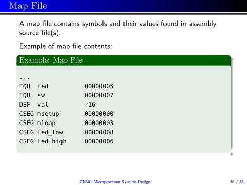
A map file contains symbols and their values found in assemblysource file(s).Example of map file contents:
Example: Map File
...EQU led 00000005EQU sw 00000007DEF val r16CSEG msetup 00000000CSEG mloop 00000003CSEG led_low 00000008CSEG led_high 00000006
CN361 Microprocessor Systems Design 36 / 38

List File
Example of list file contents:
Example: List File
....cseg ; this is code segment.org 0x0000 ; start this code at 0x0000msetup:
000000 9a25 sbi DDRB, PB5 ; set PB5 as output000001 9857 cbi DDRD, PD7 ; set PD7 as input000002 9a5f sbi PORTD, PD7 ; enable pull-up resistor on PD7
mloop:000003 b109 in val, PIND ; read Port D000004 3800 cpi val, (1<<sw)000005 f411 brne led_low ; if sw is not set
led_high:000006 9a2d sbi PORTB, led ; turn on LED if sw is set000007 cffb rjmp mloop
led_low:000008 982d cbi PORTB, led ; turn off LED if sw is cleared000009 cff9 rjmp mloop...
CN361 Microprocessor Systems Design 37 / 38

Hex File
A hex file refers to a standard file format representing the objectcode of a program suitable for downloading to the target.There are two file formats in use:
Intel HexMotorola S-record
Example of Intel Hex file contents:
Example: Hex File
:020000020000FC:10000000259A57985F9A09B1003811F42D9AFBCFC1:040010002D98F9CF5F:00000001FF
CN361 Microprocessor Systems Design 38 / 38