Embed Size (px)
Citation preview
Human Computer Interaction Laboratory
@jonfroehlich Assistant Professor Computer Science
CMSC838 Tangible Interactive Computing
Week 15 | Lecture 27 | May 5, 2015 Using ICs to Expand Arduino Functionality

TODAY’S LEARNING GOALS
1. Learn about expanding Arduino’s capabilities using
ICs
2. Learn how use a common IC: 74HC595
3. Discuss Final Projects
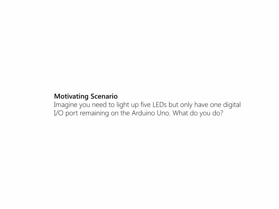
Motivating Scenario
Imagine you need to light up five LEDs but only have one digital
I/O port remaining on the Arduino Uno. What do you do?

Motivating Scenario
Imagine you need to light up eight LEDs but only have three
digital I/O ports remaining on the Arduino Uno. What do you do?

Motivating Scenario
Imagine you need to light up eight LEDs but only have three
digital I/O ports remaining on the Arduino Uno. What do you do?
You could:
• Switch to an Arduino Mega
• Find a shield like a MUX Shield from Sparkfun that
expands your I/O ports
• Use a shift register IC!

USING THE UBIQUITOUS 74HC595 SHIFT REGISTER Night Rider Shift Register Example based on Chapter 7 of Jeremy Blum’s Exploring Arduino book
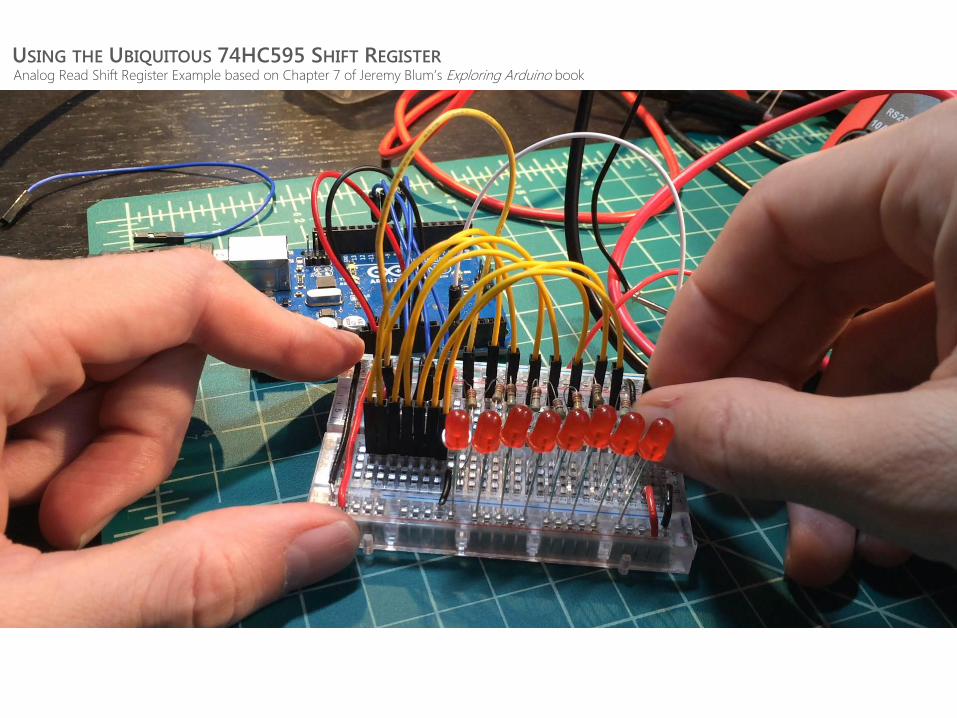
USING THE UBIQUITOUS 74HC595 SHIFT REGISTER Analog Read Shift Register Example based on Chapter 7 of Jeremy Blum’s Exploring Arduino book

THE 74HC595 8-BIT SHIFT REGISTER
The 74HC595 is an 8-bit serial-in, parallel-out shift register. This means that you load the data into the
shift register serially but can output it simultaneously (using the clock line, the data line, and the latch)
[sources: Chapter 7 of Jeremy Blum’s Exploring Arduino book; https://learn.sparkfun.com/tutorials/shift-registers; https://www.sparkfun.com/datasheets/IC/SN74HC595.pdf]
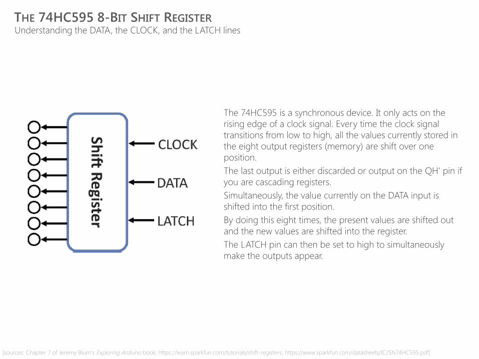
THE 74HC595 8-BIT SHIFT REGISTER Understanding the DATA, the CLOCK, and the LATCH lines
[sources: Chapter 7 of Jeremy Blum’s Exploring Arduino book; https://learn.sparkfun.com/tutorials/shift-registers; https://www.sparkfun.com/datasheets/IC/SN74HC595.pdf]
The 74HC595 is a synchronous device. It only acts on the
rising edge of a clock signal. Every time the clock signal
transitions from low to high, all the values currently stored in
the eight output registers (memory) are shift over one
position.
The last output is either discarded or output on the QH’ pin if
you are cascading registers.
Simultaneously, the value currently on the DATA input is
shifted into the first position.
By doing this eight times, the present values are shifted out
and the new values are shifted into the register.
The LATCH pin can then be set to high to simultaneously
make the outputs appear.

74HC595 8-BIT SHIFT REGISTER EXAMPLE Let’s say that we want to load the ‘1010 1010’ into the shift register. Recall that the DATA line is only read on the CLOCK’s
rising edge and that the output registers are only loaded with these values when the LATCH signal goes HIGH.
[sources: Chapter 7 of Jeremy Blum’s Exploring Arduino book; https://learn.sparkfun.com/tutorials/shift-registers; https://www.sparkfun.com/datasheets/IC/SN74HC595.pdf]
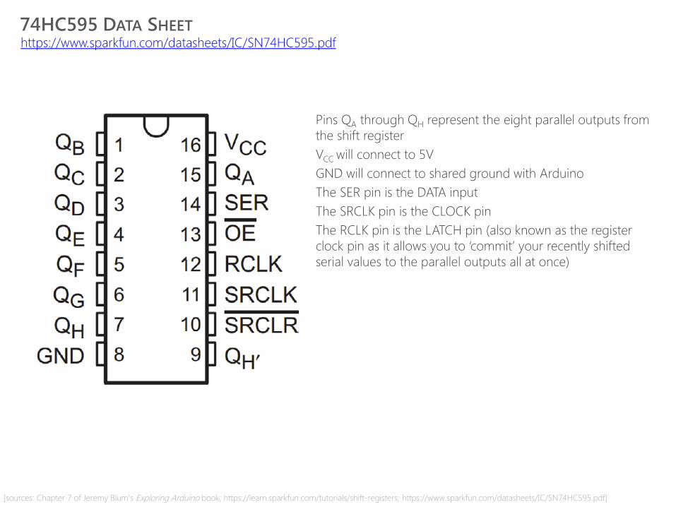
74HC595 DATA SHEET https://www.sparkfun.com/datasheets/IC/SN74HC595.pdf
Pins QA through QH represent the eight parallel outputs from
the shift register
VCC will connect to 5V
GND will connect to shared ground with Arduino
The SER pin is the DATA input
The SRCLK pin is the CLOCK pin
The RCLK pin is the LATCH pin (also known as the register
clock pin as it allows you to ‘commit’ your recently shifted
serial values to the parallel outputs all at once)
[sources: Chapter 7 of Jeremy Blum’s Exploring Arduino book; https://learn.sparkfun.com/tutorials/shift-registers; https://www.sparkfun.com/datasheets/IC/SN74HC595.pdf]
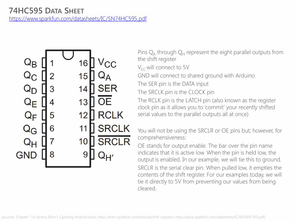
74HC595 DATA SHEET https://www.sparkfun.com/datasheets/IC/SN74HC595.pdf
Pins QA through QH represent the eight parallel outputs from
the shift register
VCC will connect to 5V
GND will connect to shared ground with Arduino
The SER pin is the DATA input
The SRCLK pin is the CLOCK pin
The RCLK pin is the LATCH pin (also known as the register
clock pin as it allows you to ‘commit’ your recently shifted
serial values to the parallel outputs all at once)
You will not be using the SRCLR or OE pins but; however, for
comprehensiveness:
OE stands for output enable. The bar over the pin name
indicates that it is active low. When the pin is held low, the
output is enabled. In our example, we will tie this to ground.
SRCLR is the serial clear pin. When pulled low, it empties the
contents of the shift register. For our examples today, we will
tie it directly to 5V from preventing our values from being
cleared.
[sources: Chapter 7 of Jeremy Blum’s Exploring Arduino book; https://learn.sparkfun.com/tutorials/shift-registers; https://www.sparkfun.com/datasheets/IC/SN74HC595.pdf]
IN-CLASS EXERCISES
Scenario 1
Simply load a bit value into the shift register and represent it via an LED array
Scenario 2
Create the night rider example
Scenario 3
Make a sensor-based bar graph where the LEDs represent the sensor’s value.
Scenario 4 (if time)
Work with a partner to cascade your two shift register circuits together using
one Arduino and still just three wires (this doubles the number of outputs while
using the same number of pins on the Arduino)
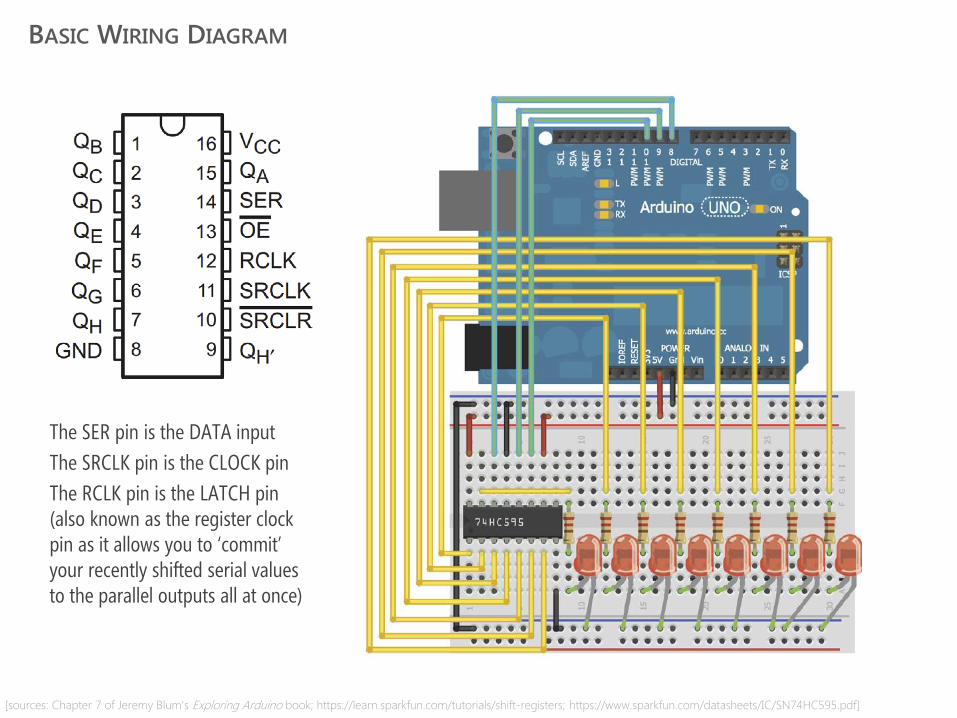
BASIC WIRING DIAGRAM
[sources: Chapter 7 of Jeremy Blum’s Exploring Arduino book; https://learn.sparkfun.com/tutorials/shift-registers; https://www.sparkfun.com/datasheets/IC/SN74HC595.pdf]
The SER pin is the DATA input
The SRCLK pin is the CLOCK pin
The RCLK pin is the LATCH pin (also known as the register clock pin as it allows you to ‘commit’ your recently shifted serial values to the parallel outputs all at once)

SCENARIO 1
[sources: Chapter 7 of Jeremy Blum’s Exploring Arduino book; https://learn.sparkfun.com/tutorials/shift-registers; https://www.sparkfun.com/datasheets/IC/SN74HC595.pdf]
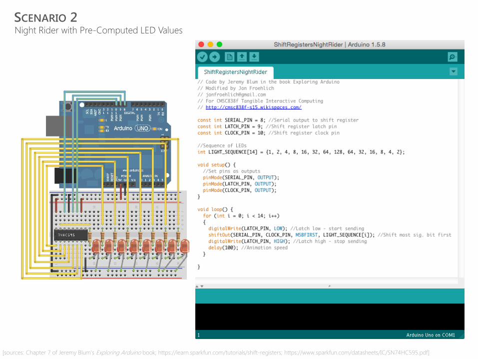
SCENARIO 2 Night Rider with Pre-Computed LED Values
[sources: Chapter 7 of Jeremy Blum’s Exploring Arduino book; https://learn.sparkfun.com/tutorials/shift-registers; https://www.sparkfun.com/datasheets/IC/SN74HC595.pdf]
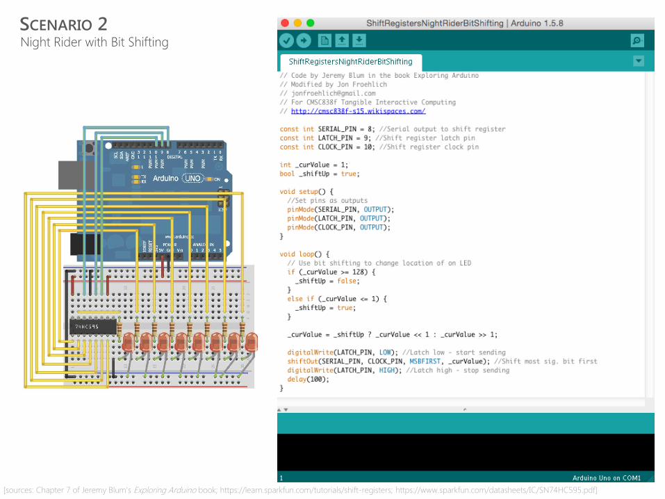
SCENARIO 2 Night Rider with Bit Shifting
[sources: Chapter 7 of Jeremy Blum’s Exploring Arduino book; https://learn.sparkfun.com/tutorials/shift-registers; https://www.sparkfun.com/datasheets/IC/SN74HC595.pdf]

SCENARIO 3 Sensor bar graph
[sources: Chapter 7 of Jeremy Blum’s Exploring Arduino book; https://learn.sparkfun.com/tutorials/shift-registers; https://www.sparkfun.com/datasheets/IC/SN74HC595.pdf]
HELPFUL RESOURCES
http://www.arduino.cc/en/Tutorial/ShiftOut
https://learn.adafruit.com/adafruit-arduino-lesson-4-eight-leds/other-things-to-do
Chapter 7 “Shift Registers” in Jeremey Blum’s book Exploring Arduino


![Transfusionsindikationen bei malignen Erkrankungen · Scenario 1: number of patients Scenario 2: number of patients % of patients (mean) [46] Scenario 1: number of patients Scenario](https://img.dokumen.tips/doc/110x75/605ea3d56540f665aa09ac74/transfusionsindikationen-bei-malignen-scenario-1-number-of-patients-scenario-2.jpg)