Embed Size (px)
Citation preview
1
Fast Manual Instruction of
Network Video CMS V1.0
2
CATALOGUE
1.1 SUMMARY ................................................................................................. 3
1.2 FEATURES .................................................................................................. 3
CHAPTER 2 INSTALLATION INSTRUCTION ........................................... 5
2.1RUNNING ENVIRONMENT ............................................................................. 5
2.2 INSTALLATION STEPS ................................................................................... 5
CHAPTER 3 INTRODUCTION OF BASIC FUNCTIONS ........................... 9
3.1 CMS OPERATION MAIN MENU .................................................................... 9
4.1PREVIEW ..................................................................................................... 12
4.2RIGHT-CLICK MENU.................................................................................... 12
4.3 PTZ CONTROL ........................................................................................... 13
4.4COLOR ........................................................................................................ 14
CHAPTER 5 SYSTEM ................................................................................... 15
5.1 DEVICE MANAGER ..................................................................................... 15
5.2LOCAL CONFIG ......................................................................................... 18
5.3 DEVICE CONFIG. ........................................................................................ 24
5.4 USER .......................................................................................................... 36
5.5LOCAL LOG ................................................................................................ 37
CHAPTER 6 RECORD ................................................................................... 39
6.1 PLAYBACK ................................................................................................. 39
CHAPTER 7 ADVANCED .............................................................................. 44
7.1 DECODER ................................................................................................... 44
7.2E-MAP ....................................................................................................... 51
7.3 TOUR ......................................................................................................... 55
7.4 TASK CONFIG. ............................................................................................ 57
APPENDIX A ABBREVIATIONS .................................................................. 59
APPENDIX BMAIN PARAMETER .............................................................. 60
3
Chapter 1 Software Instruction 1.1 Summary
This is a Central Control Software with powerful function and distributed architecture, integrate
many windows, users, and languages, It support bidirectional talk, video conference, classic of electronic
map, alarm center, and be compatible with Other extended products and single directly connected devices
surveillance system as one. Its electronic map design with friendly interface, easy to operate and purview
set.
This software is only for connecting different devices (DVR, DVS, etc), the manual only describe the
software, for specific equipment features, please refer to related product manuals.
This manual is for those who are responsible for planning, executing or reviewing the hardware
installation of Network Video Surveillance software. You should have the basic operation knowledge and
experience of related equipment (DVR, DVS, etc).
1.2 Features
1.1.1 User and Purview Management
Support N level organization management, user management and purview setting
1.1.2 Data Interface Technology Adopted
All data interaction use data interface technology, and support different database sizes flexibility,
such as SQL, MYSQL, XML data and so on.
1.1.3Intelligent Video Transport Protocol
Intelligent Video Transport Protocol can do Maximize the use of network bandwidth, especially on the
condition of Front-end network bandwidth limited, when to assure system based on high quality image in
very low network bandwidth, it can work well.
1.1.4 Scalable Distributed Network Architecture
Support multi servers coordinated running, intelligent load balancing, flexibility to add server and
enhance the system capacity effectively on the condition of integrity assurance.
1.1.5Dynamically Adjust Decode Buffering.
Flexibility in adjusting the fluency or real-time of video images when real time monitoring, which can
meet different users need. The former emphasize the fluency of video images, while the latter emphasize
the real-time of video images.
4
1.1.6Adopting Shelf Technology, Modular Development and Flexible to Assembly Application
Solutions.
Adopt shelf technology to develop hierarchically and modularly. With rich middleware service, users
can assemble different applications flexibly.
1.1.7High Operability
Within purview limitation, users can easily control and set each monitor point through the system, it
also integrates-map.
1.1.8High Integration
The system integrates other related information, such as alarming, voice and so on.
1.1.9 High reliability
The system designs a special fault tolerance measures to assure data Integrity and system running
reliability.
1.1.10 Good Scalability
The system designs for service. It has good scalability and adaptability to protect user investment
maximumly.
1.1.11 Support Network Management and Load Balancing
1.1.12Support User DIY Interface and Multi Languages
1.1.13 Support E-map
1.1.14 Support Simultaneous 4 Channels Real Time Playback
1.1.15 Support Connecting Multi Devices and View Multi Videos(real time monitoring and
playback)
1.1.16XML Data Storage
1.1.17 Support Multi RS Keyboard Protocols.
1.1.18 Support Multi Alarming Device, Like CK, Vista, etc
1.1.19 Support Multi three-dimensional positioning Speed Cameras Protocol, easy to realize
three-dimensional positioning in Preview Area
1.1.20 Support multi manufactures access to our device, such as Dahua, Hikvision, etc.
5
Chapter 2 Installation Instruction 2.1Running Environment
2.1.1 Hardware:
CPU P4/2.0G
Graphics card must support hardware scaling (such as ATI, TNT2 and PRO, but suggest
ATI9800 or above, dual channels), and the memory over 128M/128bit.
Note: Good configuration for memory, graphics cards and CPU are needed for many screens
decompression.
Network card: 100/1000M
2.1.2 Software:
The CMS support Vista/WinXp/Win2000/Win2003/Win2007, not for windows 98.
Please close all Antivirus Software and firewall so that it can write running program correctly and
completely in the control center before installing the software, or it will not search any devices.
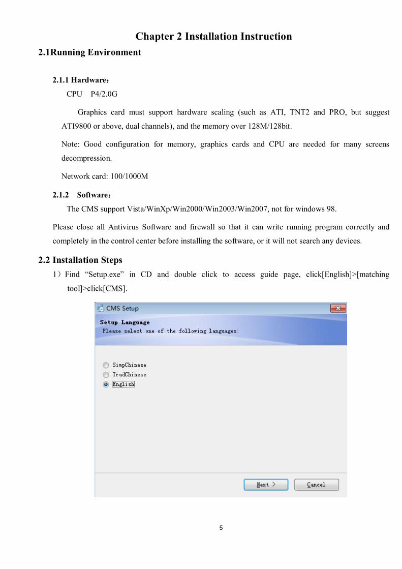
2.2 Installation Steps 1)Find “Setup.exe” in CD and double click to access guide page, click[English]>[matching
tool]>click[CMS].
6
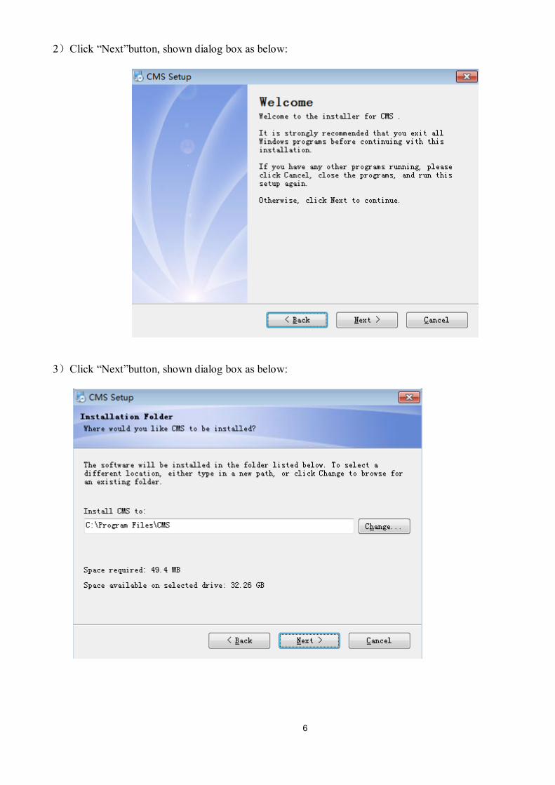
2)Click “Next”button, shown dialog box as below:
3)Click “Next”button, shown dialog box as below:
7
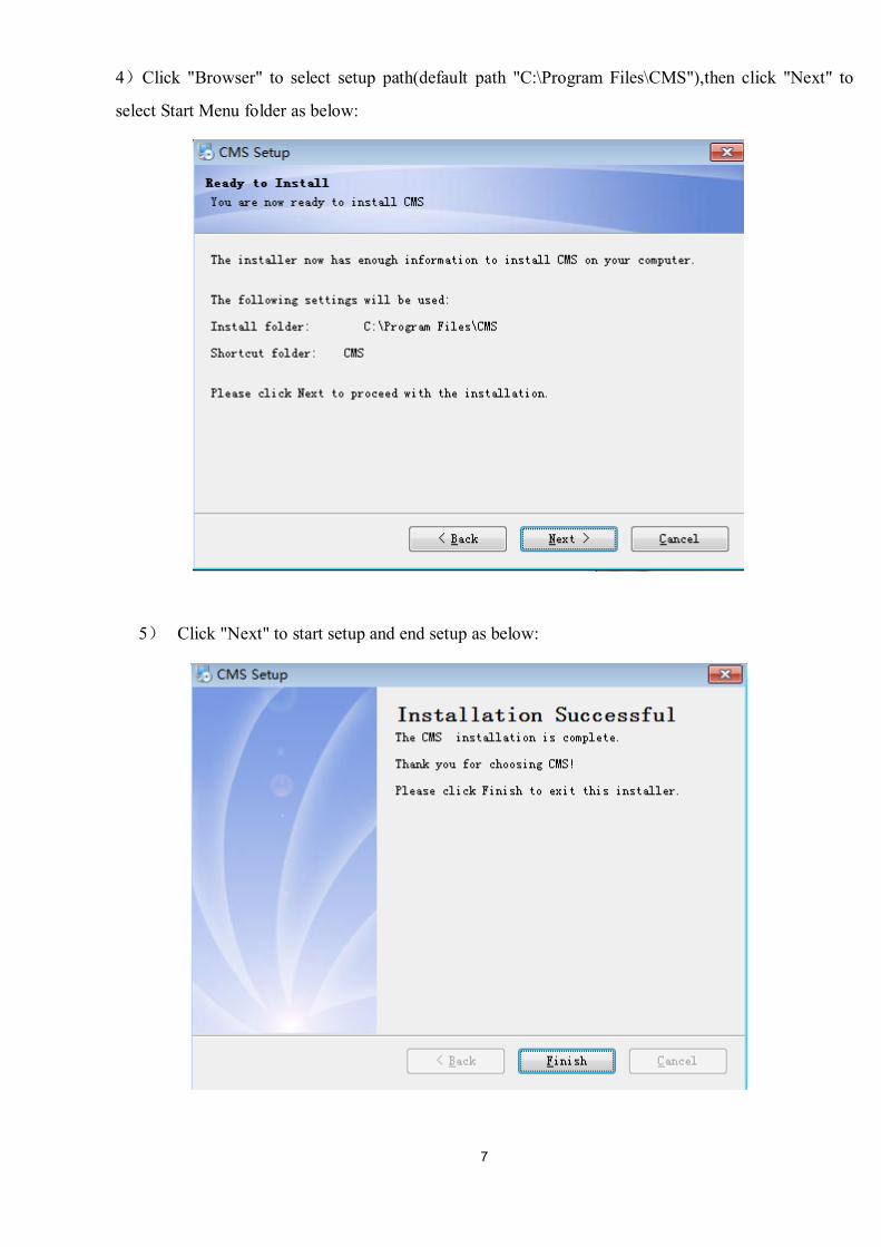
4)Click "Browser" to select setup path(default path "C:\Program Files\CMS"),then click "Next" to
select Start Menu folder as below:
5) Click "Next" to start setup and end setup as below:

8
6)Click "Finish" to end the setup, at the same time it will come up this icon in the desktop.
Please follow Chapter 3,4,5,6,7 instructions to operate this software after finish installation.
9
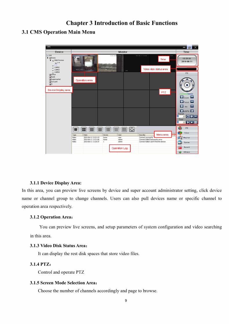
Chapter 3 Introduction of Basic Functions 3.1 CMS Operation Main Menu
3.1.1 Device Display Area: In this area, you can preview live screens by device and super account administrator setting, click device
name or channel group to change channels. Users can also pull devices name or specific channel to
operation area respectively.
3.1.2 Operation Area:
You can preview live screens, and setup parameters of system configuration and video searching
in this area.
3.1.3 Video Disk Status Area:
It can display the rest disk spaces that store video files.
3.1.4 PTZ:
Control and operate PTZ
3.1.5 Screen Mode Selection Area:
Choose the number of channels accordingly and page to browse.
10
3.1.6 Operation Log:
It will record and display any operation information when setup and operating.
3.1.7 Menu Area:
Users could set single menu and sub-menu in this area, select relevant menus to operate video
surveillance system in the control center.
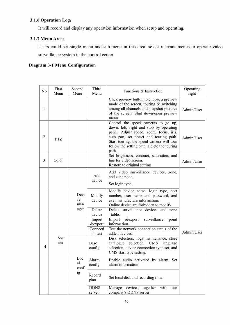
Diagram 3-1 Menu Configuration
No First Menu
Second Menu
Third Menu Functions & Instruction Operating
right
1
Click preview button to choose a preview mode of the screen, touring & switching among all channels and snapshot pictures of the screen. Shut down/open preview menu
Admin/User
2 PTZ
Control the speed cameras to go up, down, left, right and stop by operating panel. Adjust speed, zoom, focus, iris, auto pan, set preset and touring path. Start touring, the speed camera will tour follow the setting path. Delete the touring path.
Admin/User
3 Color Set brightness, contract, saturation, and hue for video screen. Restore to original setting
Admin/User
4
System
Device manager
Add device
Add video surveillance devices, zone, and zone node.
Set login type.
Admin/User
Modify device
Modify device name, login type, port number, user name and password, and even manufacture information. Online device are forbidden to modify
Delete device
Delete surveillance devices and zone table.
Import &export
Import &export surveillance point information.
Connection test
Test the network connection status of the added devices.
Local config
Base config
Disk selection, logs maintenance, store catalogue selection, CMS language selection, device connection type set, and CMS start type setting.
Alarm config
Enable audio activated by alarm. Set alarm information
Record plan Set local disk and recording time.
DDNS server
Manage devices together with our company’s DDNS server
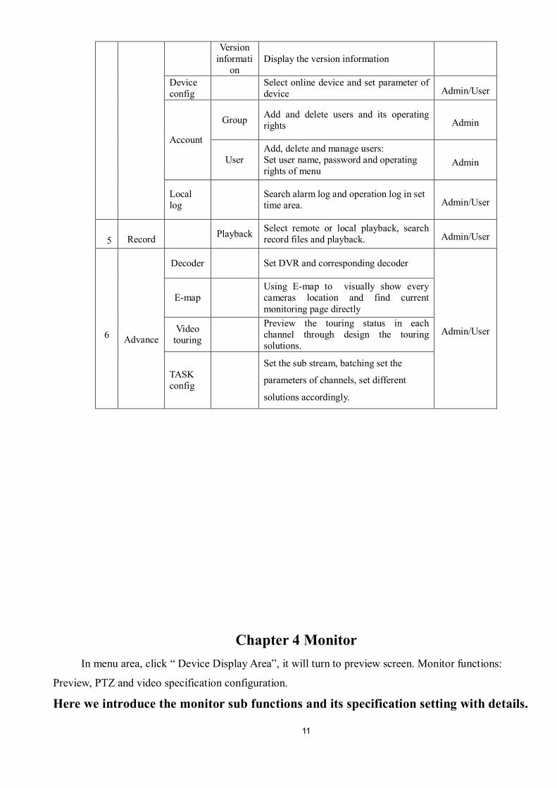
11
Version informati
on Display the version information
Device config Select online device and set parameter of
device Admin/User
Account
Group Add and delete users and its operating rights Admin
User Add, delete and manage users: Set user name, password and operating rights of menu
Admin
Local log Search alarm log and operation log in set
time area. Admin/User
5
Record Playback Select remote or local playback, search
record files and playback. Admin/User
6
Advance
Decoder Set DVR and corresponding decoder
Admin/User
E-map Using E-map to visually show every cameras location and find current monitoring page directly
Video touring
Preview the touring status in each channel through design the touring solutions.
TASK config
Set the sub stream, batching set the
parameters of channels, set different
solutions accordingly.
Chapter 4 Monitor
In menu area, click “ Device Display Area”, it will turn to preview screen. Monitor functions:
Preview, PTZ and video specification configuration.
Here we introduce the monitor sub functions and its specification setting with details.

12
4.1Preview In operation area, users can select preview type, or screenshot in each single channel, or shut down
the preview page. Function buttons and instructions of preview in operation area shown as below.
Diagram 4-2 Function buttons and instructions of preview
No. Button Meanings
1
“1 screen preview”button. Click it to preview full screen for every channel。
2
“4 screens preview”button. Click it to preview 4 screens.
3
“9 screens preview”button Click it to preview 9 screens.
4
“16 screens preview”button. Click it to preview 16 screens.
5
“25 screens preview”button. Click it to preview 25 screens.
6
“36 screens preview”button. Click it to preview 36 screens.
7
“64 screens preview”button. Click it to preview 64 screens.
8
“full screen preview”button. Click it to enter full screen interface.
9
“pagecontrol”button. Click to page down and page up the preview pages.
10
“audio”button. Click to enable audio heard on preview page.
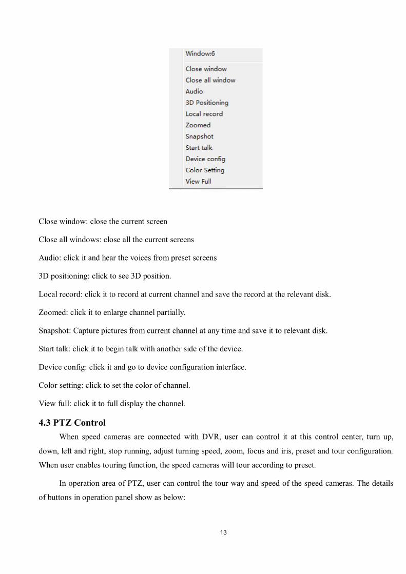
4.2Right-click Menu At operating area, user can do below operation by right-click:
13
Close window: close the current screen
Close all windows: close all the current screens
Audio: click it and hear the voices from preset screens
3D positioning: click to see 3D position.
Local record: click it to record at current channel and save the record at the relevant disk.
Zoomed: click it to enlarge channel partially.
Snapshot: Capture pictures from current channel at any time and save it to relevant disk.
Start talk: click it to begin talk with another side of the device.
Device config: click it and go to device configuration interface.
Color setting: click to set the color of channel.
View full: click it to full display the channel.
4.3 PTZ Control When speed cameras are connected with DVR, user can control it at this control center, turn up,
down, left and right, stop running, adjust turning speed, zoom, focus and iris, preset and tour configuration.
When user enables touring function, the speed cameras will tour according to preset.
In operation area of PTZ, user can control the tour way and speed of the speed cameras. The details
of buttons in operation panel show as below:
14
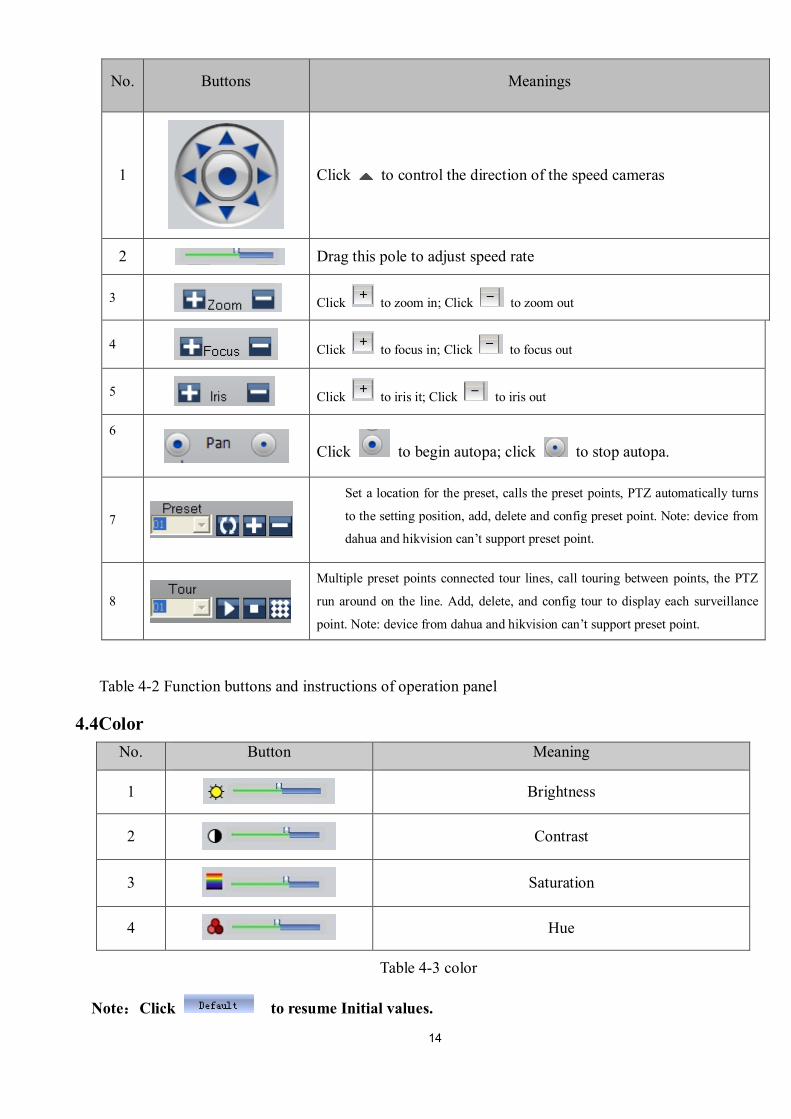
No. Buttons Meanings
1
Click to control the direction of the speed cameras
2 Drag this pole to adjust speed rate
3 Click to zoom in; Click to zoom out
4 Click to focus in; Click to focus out
5 Click to iris it; Click to iris out
6
Click to begin autopa; click to stop autopa.
7
Set a location for the preset, calls the preset points, PTZ automatically turns
to the setting position, add, delete and config preset point. Note: device from
dahua and hikvision can’t support preset point.
8
Multiple preset points connected tour lines, call touring between points, the PTZ
run around on the line. Add, delete, and config tour to display each surveillance
point. Note: device from dahua and hikvision can’t support preset point.
Table 4-2 Function buttons and instructions of operation panel
4.4Color No. Button Meaning
1 Brightness
2 Contrast
3 Saturation
4 Hue
Table 4-3 color
Note:Click to resume Initial values.
15
Chapter 5 System
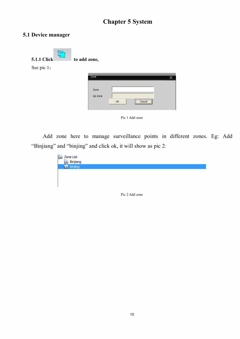
5.1 Device manager
5.1.1 Click to add zone, See pic 1:
Pic 1 Add zone
Add zone here to manage surveillance points in different zones. Eg: Add
“Binjiang” and “binjing” and click ok, it will show as pic 2:
Pic 2 Add zone
16
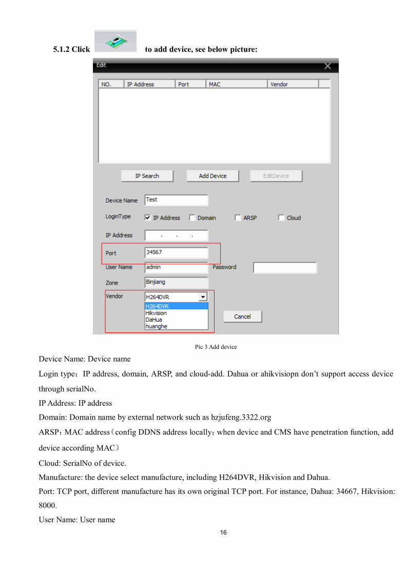
5.1.2 Click to add device, see below picture:
Pic 3 Add device
Device Name: Device name
Login type:IP address, domain, ARSP, and cloud-add. Dahua or ahikvisiopn don’t support access device
through serialNo.
IP Address: IP address
Domain: Domain name by external network such as hzjufeng.3322.org
ARSP:MAC address(config DDNS address locally;when device and CMS have penetration function, add
device according MAC)
Cloud: SerialNo of device.
Manufacture: the device select manufacture, including H264DVR, Hikvision and Dahua.
Port: TCP port, different manufacture has its own original TCP port. For instance, Dahua: 34667, Hikvision:
8000.
User Name: User name
17
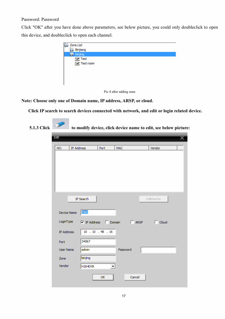
Password: Password
Click "OK" after you have done above parameters, see below picture, you could only doubleclick to open
this device, and doubleclick to open each channel.
Pic 4 after adding zone
Note: Choose only one of Domain name, IP address, ARSP, or cloud.
Click IP search to search devices connected with network, and edit or login related device.
5.1.3 Click to modify device, click device name to edit, see below picture:
18
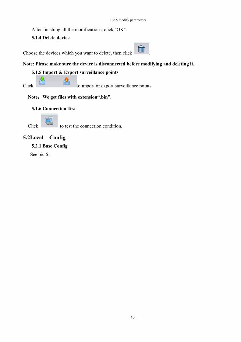
Pic 5 modify parameters
After finishing all the modifications, click "OK".
5.1.4 Delete device
Choose the devices which you want to delete, then click .
Note: Please make sure the device is disconnected before modifying and deleting it.
5.1.5 Import & Export surveillance points
Click to import or export surveillance points
Note:We get files with extension“.bin”.
5.1.6 Connection Test
Click to test the connection condition.
5.2Local Config 5.2.1 Base Config
See pic 6:
19
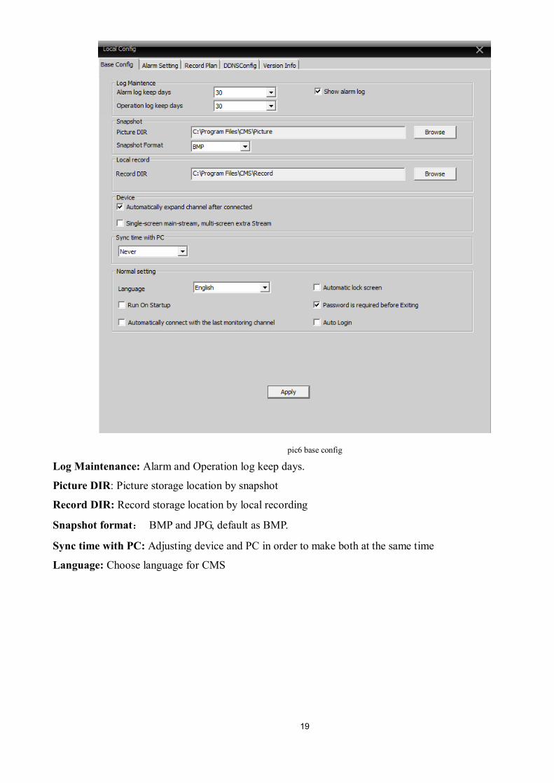
pic6 base config
Log Maintenance: Alarm and Operation log keep days.
Picture DIR: Picture storage location by snapshot
Record DIR: Record storage location by local recording
Snapshot format: BMP and JPG, default as BMP.
Sync time with PC: Adjusting device and PC in order to make both at the same time
Language: Choose language for CMS
20
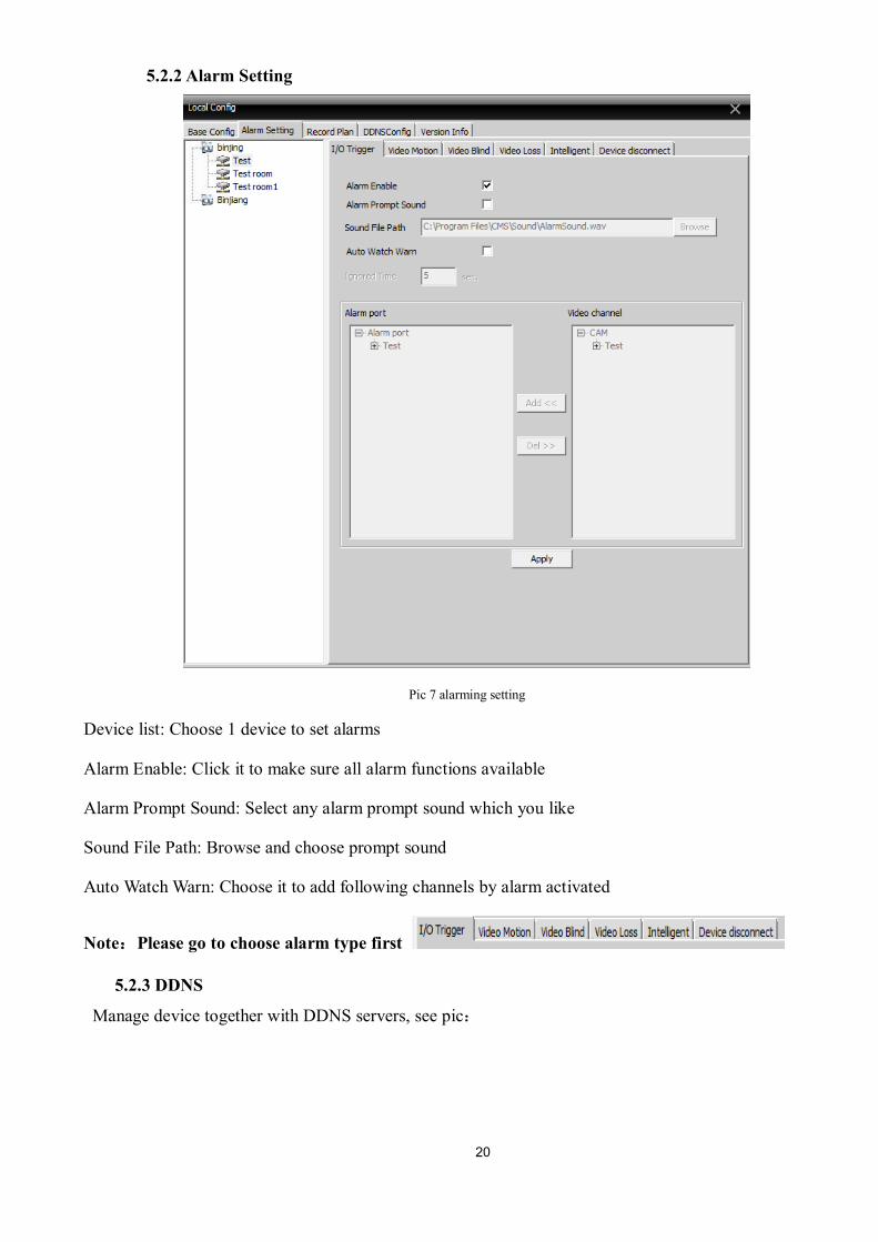
5.2.2 Alarm Setting
Pic 7 alarming setting
Device list: Choose 1 device to set alarms
Alarm Enable: Click it to make sure all alarm functions available
Alarm Prompt Sound: Select any alarm prompt sound which you like
Sound File Path: Browse and choose prompt sound
Auto Watch Warn: Choose it to add following channels by alarm activated
Note:Please go to choose alarm type first
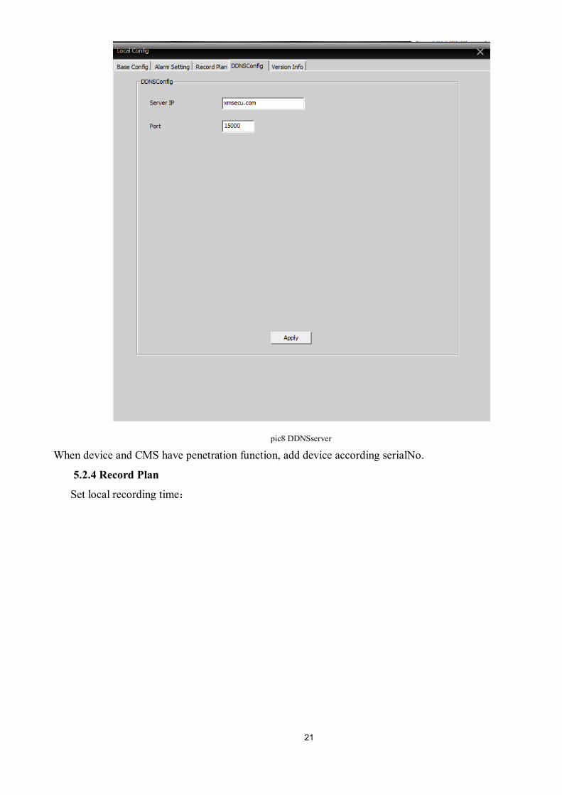
5.2.3 DDNS
Manage device together with DDNS servers, see pic:
21
pic8 DDNSserver
When device and CMS have penetration function, add device according serialNo.
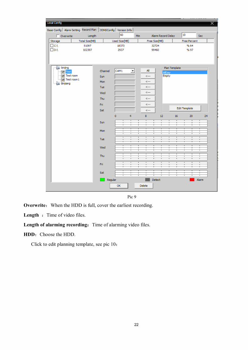
5.2.4 Record Plan
Set local recording time:
22
Pic 9
Overwrite:When the HDD is full, cover the earliest recording.
Length :Time of video files.
Length of alarming recording:Time of alarming video files.
HDD:Choose the HDD.
Click to edit planning template, see pic 10:
23
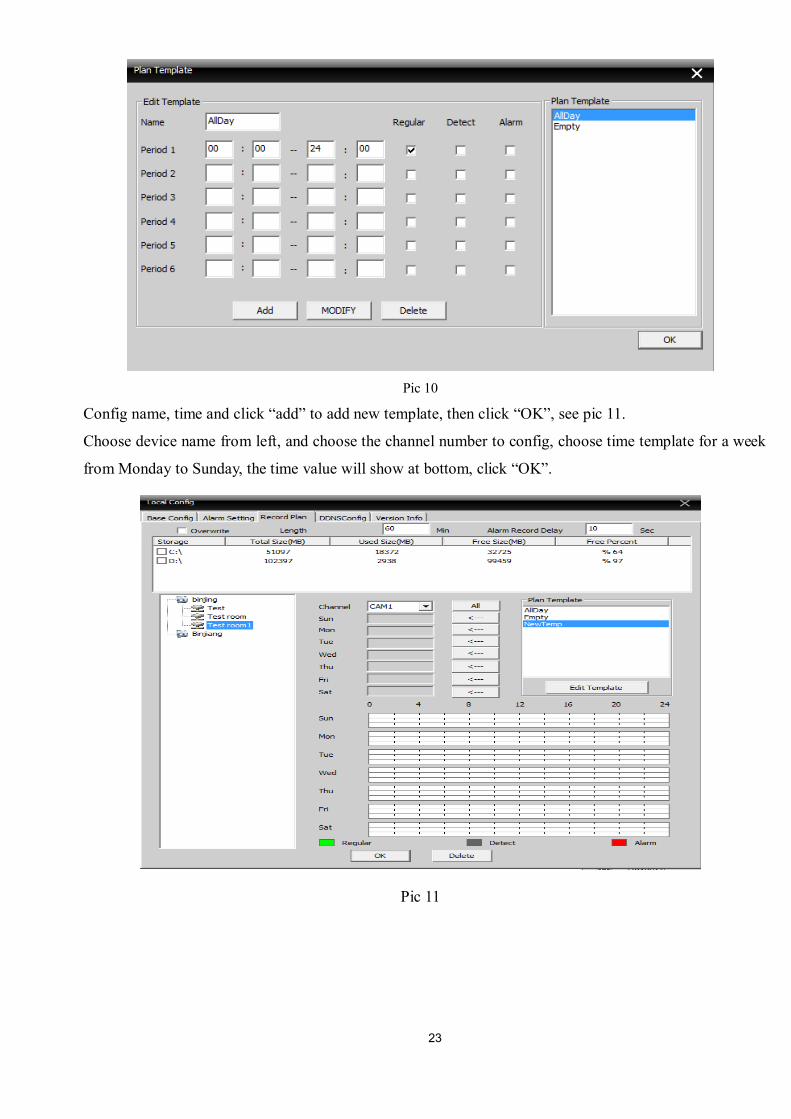
Pic 10
Config name, time and click “add” to add new template, then click “OK”, see pic 11.
Choose device name from left, and choose the channel number to config, choose time template for a week
from Monday to Sunday, the time value will show at bottom, click “OK”.
Pic 11
24
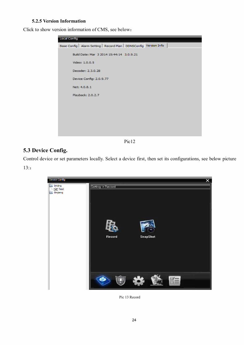
5.2.5 Version Information
Click to show version information of CMS, see below:
Pic12
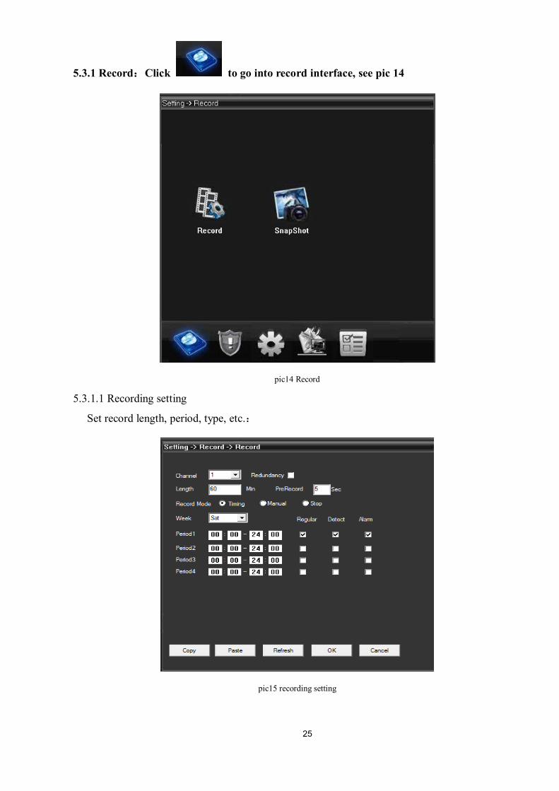
5.3 Device Config. Control device or set parameters locally. Select a device first, then set its configurations, see below picture
13::
Pic 13 Record
25
5.3.1 Record:Click to go into record interface, see pic 14
pic14 Record
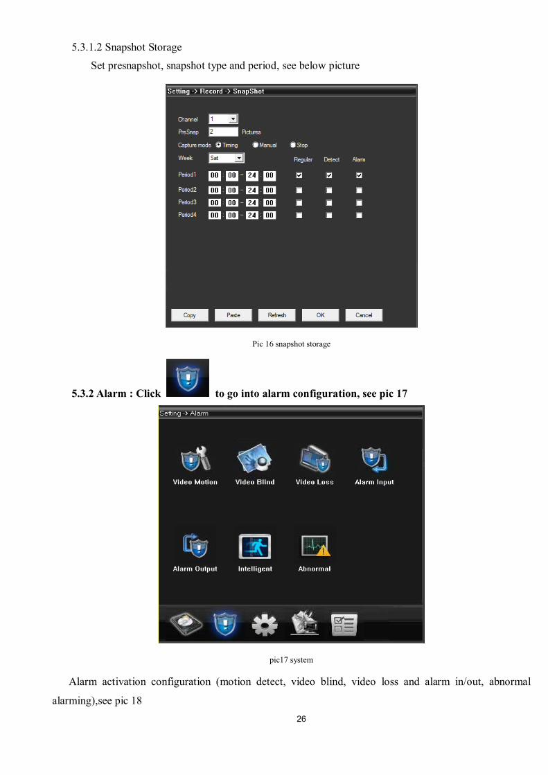
5.3.1.1 Recording setting
Set record length, period, type, etc.:
pic15 recording setting
26
5.3.1.2 Snapshot Storage
Set presnapshot, snapshot type and period, see below picture
Pic 16 snapshot storage
5.3.2 Alarm : Click to go into alarm configuration, see pic 17
pic17 system
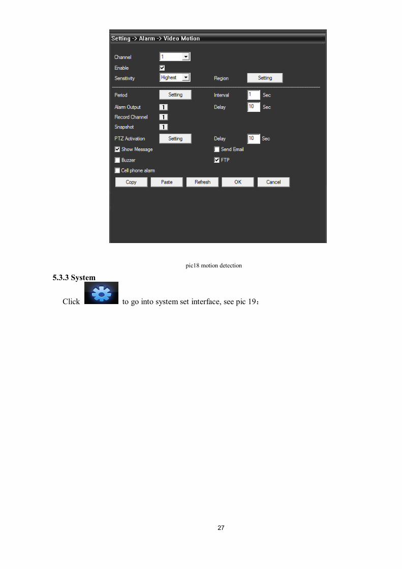
Alarm activation configuration (motion detect, video blind, video loss and alarm in/out, abnormal
alarming),see pic 18
27
pic18 motion detection
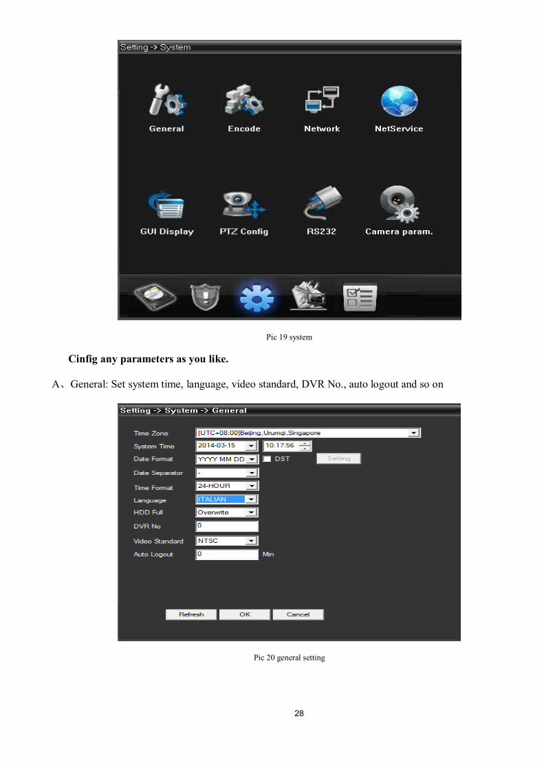
5.3.3 System
Click to go into system set interface, see pic 19:
28
Pic 19 system
Cinfig any parameters as you like.
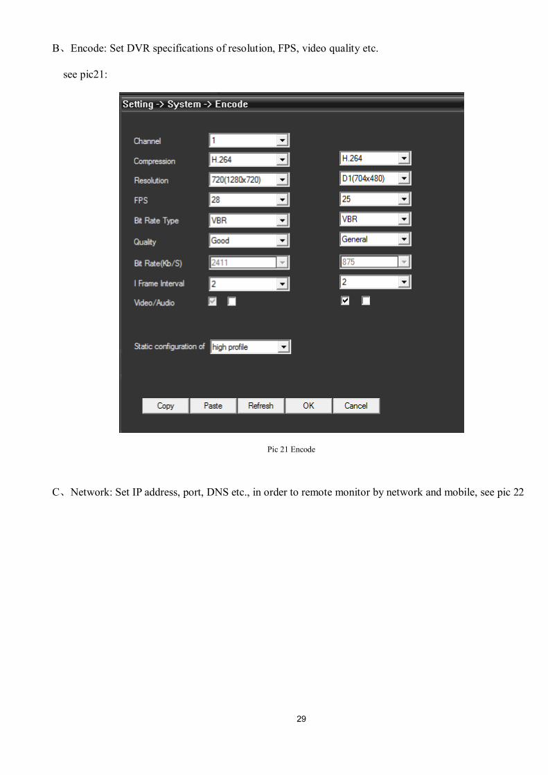
A、General: Set system time, language, video standard, DVR No., auto logout and so on
Pic 20 general setting
29
B、Encode: Set DVR specifications of resolution, FPS, video quality etc.
see pic21:
Pic 21 Encode
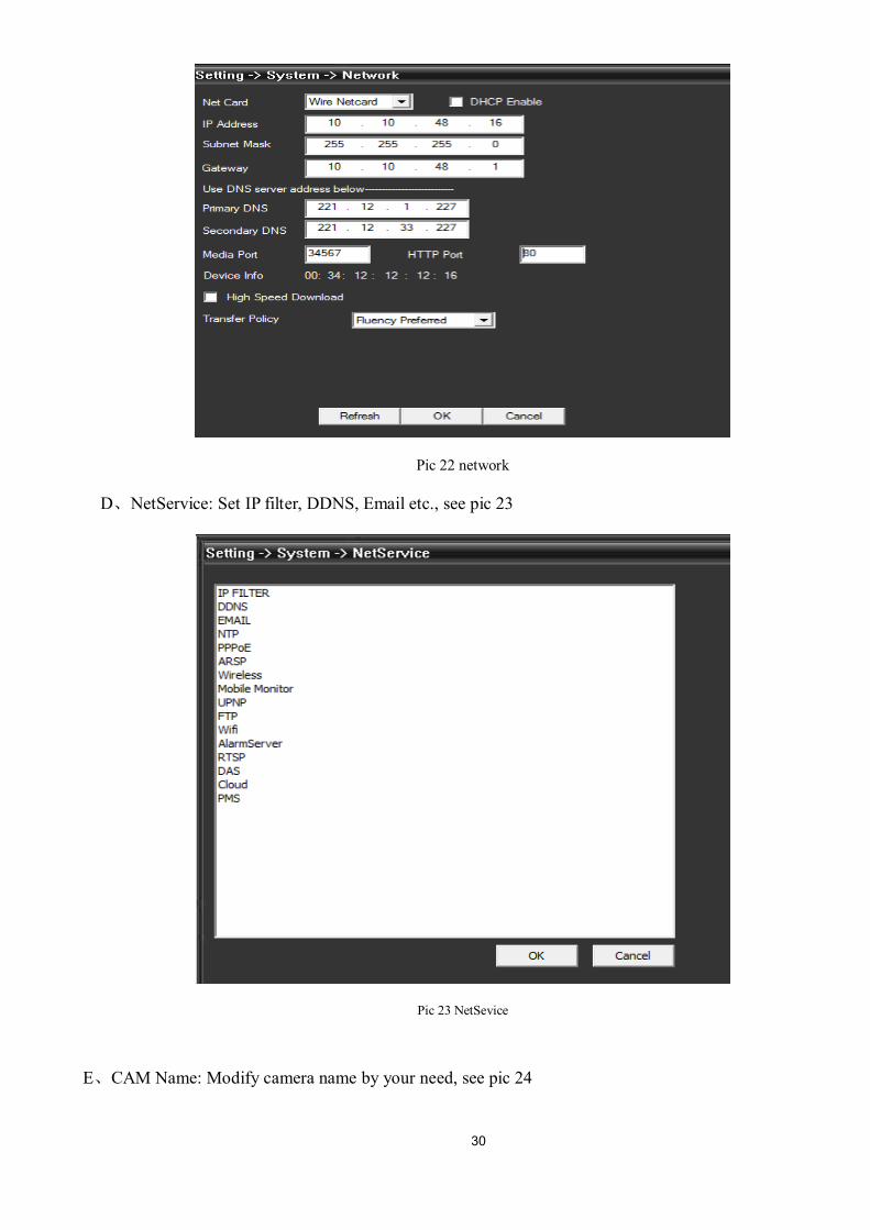
C、Network: Set IP address, port, DNS etc., in order to remote monitor by network and mobile, see pic 22
30
Pic 22 network
D、NetService: Set IP filter, DDNS, Email etc., see pic 23
Pic 23 NetSevice
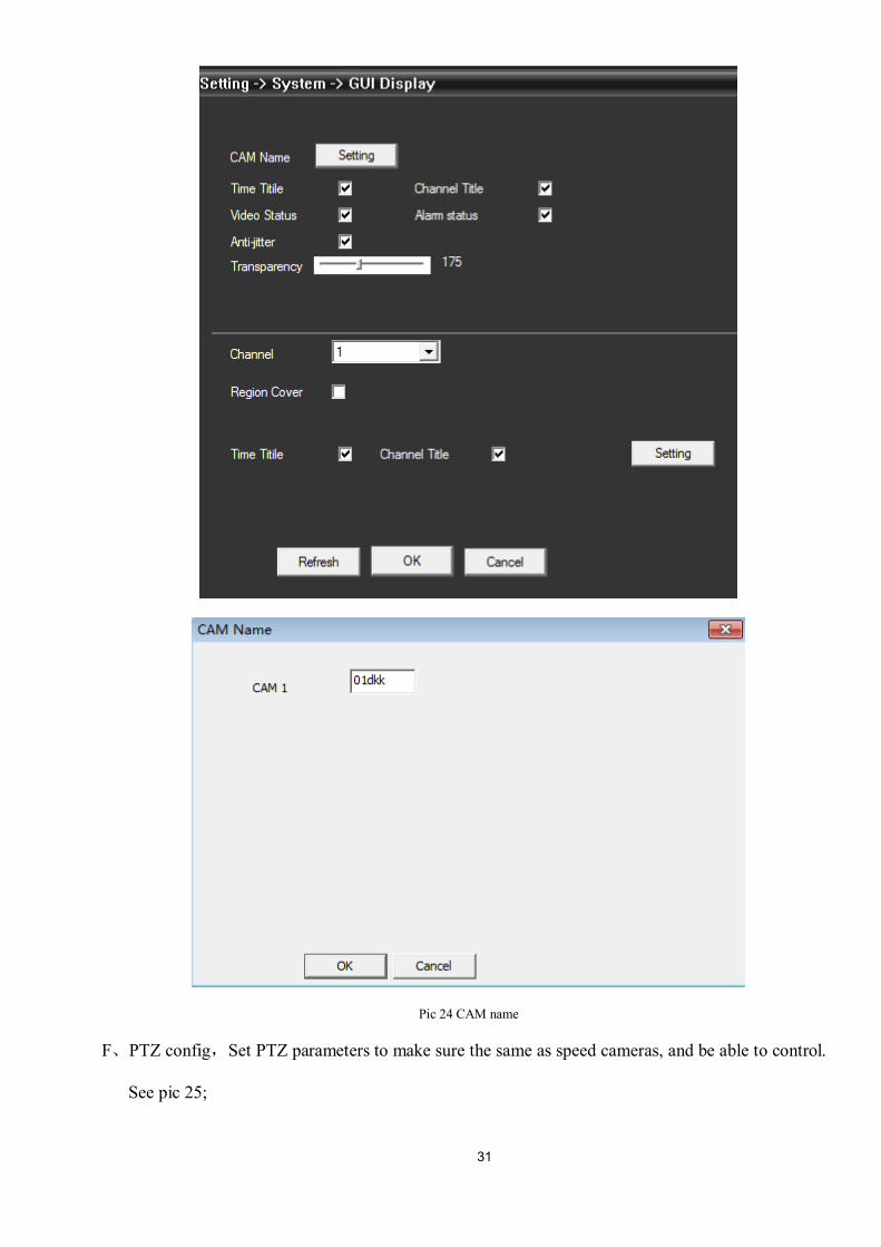
E、CAM Name: Modify camera name by your need, see pic 24
31
Pic 24 CAM name
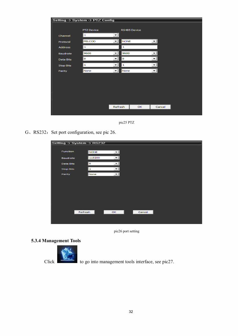
F、PTZ config,Set PTZ parameters to make sure the same as speed cameras, and be able to control.
See pic 25;
32
pic25 PTZ
G、RS232:Set port configuration, see pic 26.
pic26 port setting
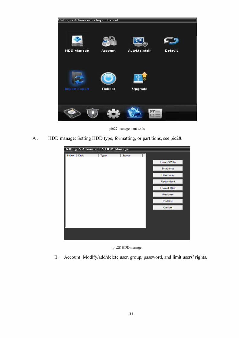
5.3.4 Management Tools
Click to go into management tools interface, see pic27.
33
pic27 management tools
A、 HDD manage: Setting HDD type, formatting, or partitions, see pic28.
pic28 HDD manage
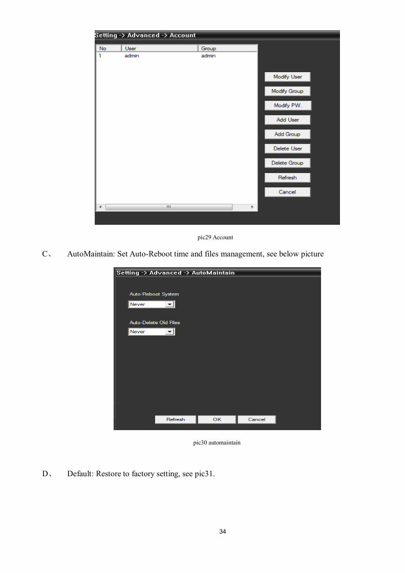
B、 Account: Modify/add/delete user, group, password, and limit users’ rights.
34
pic29 Account
C、 AutoMaintain: Set Auto-Reboot time and files management, see below picture
pic30 automaintain
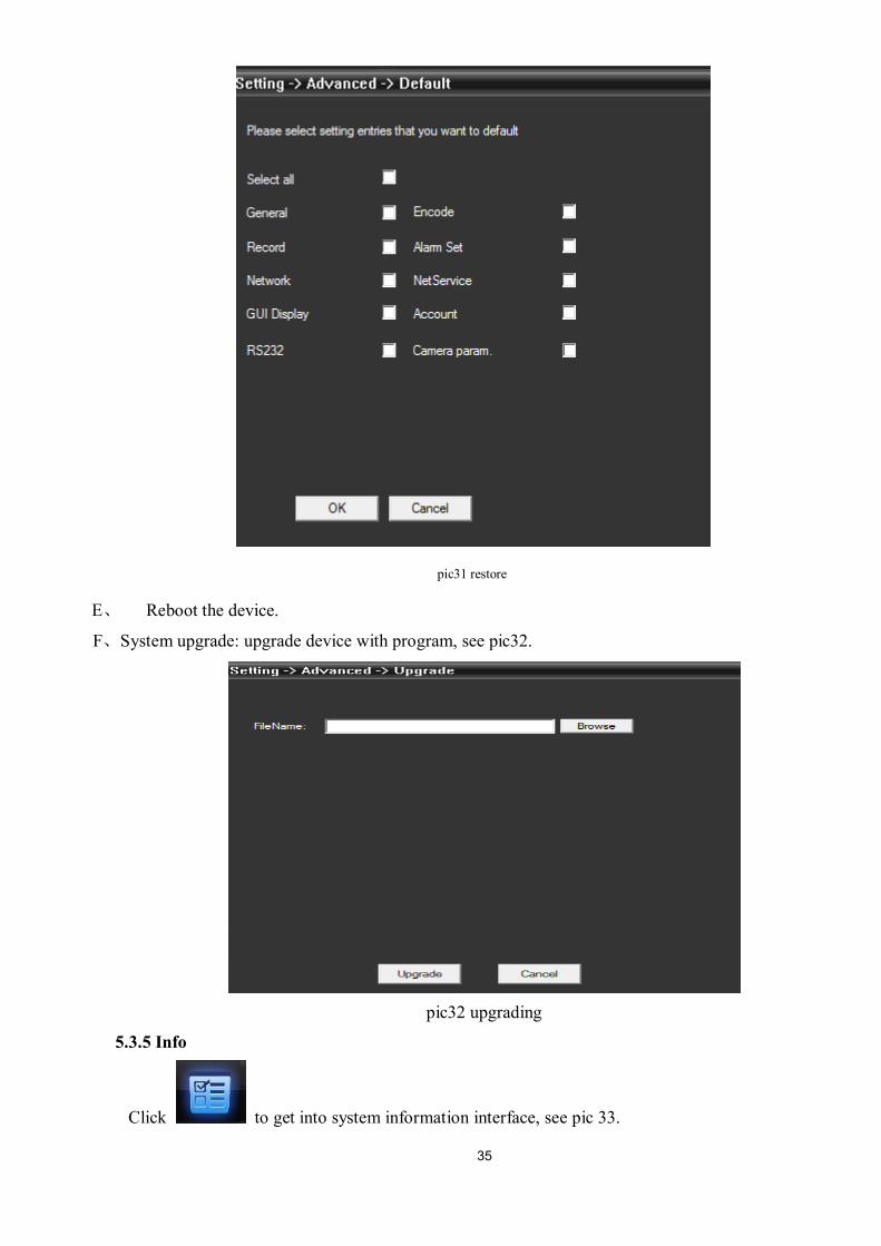
D、 Default: Restore to factory setting, see pic31.
35
pic31 restore
E、 Reboot the device.
F、System upgrade: upgrade device with program, see pic32.
pic32 upgrading
5.3.5 Info
Click to get into system information interface, see pic 33.
36
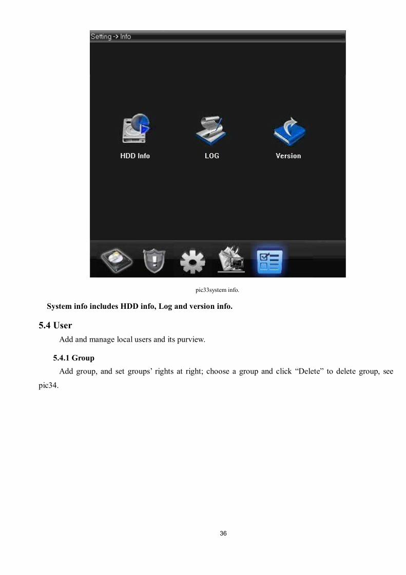
pic33system info.
System info includes HDD info, Log and version info.
5.4 User Add and manage local users and its purview.
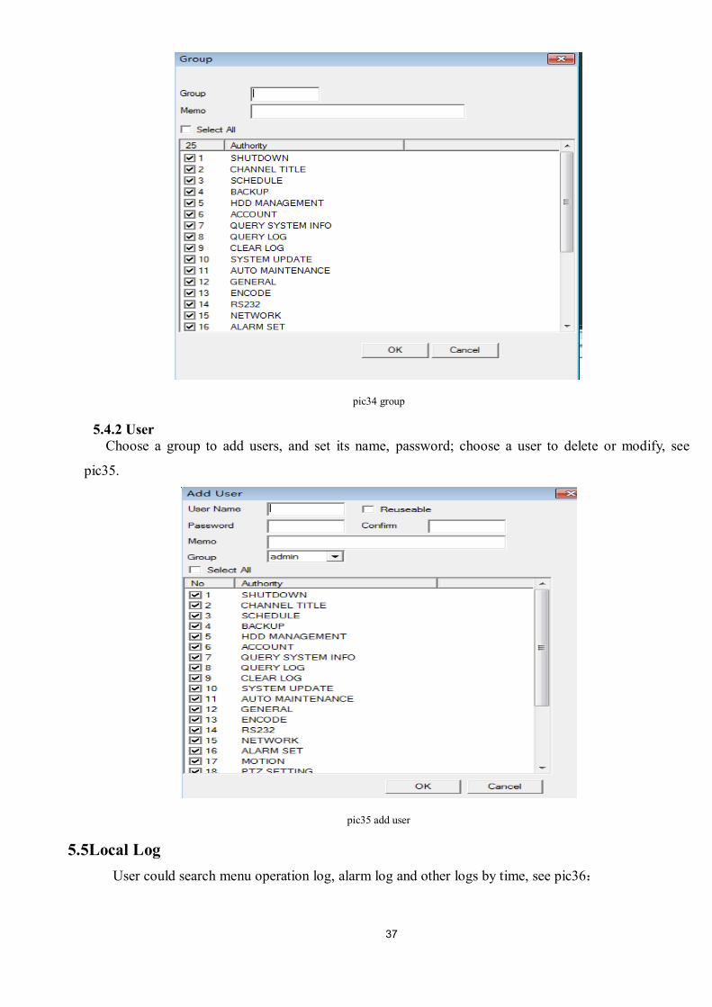
5.4.1 Group Add group, and set groups’ rights at right; choose a group and click “Delete” to delete group, see
pic34.
37
pic34 group
5.4.2 User Choose a group to add users, and set its name, password; choose a user to delete or modify, see
pic35.
pic35 add user
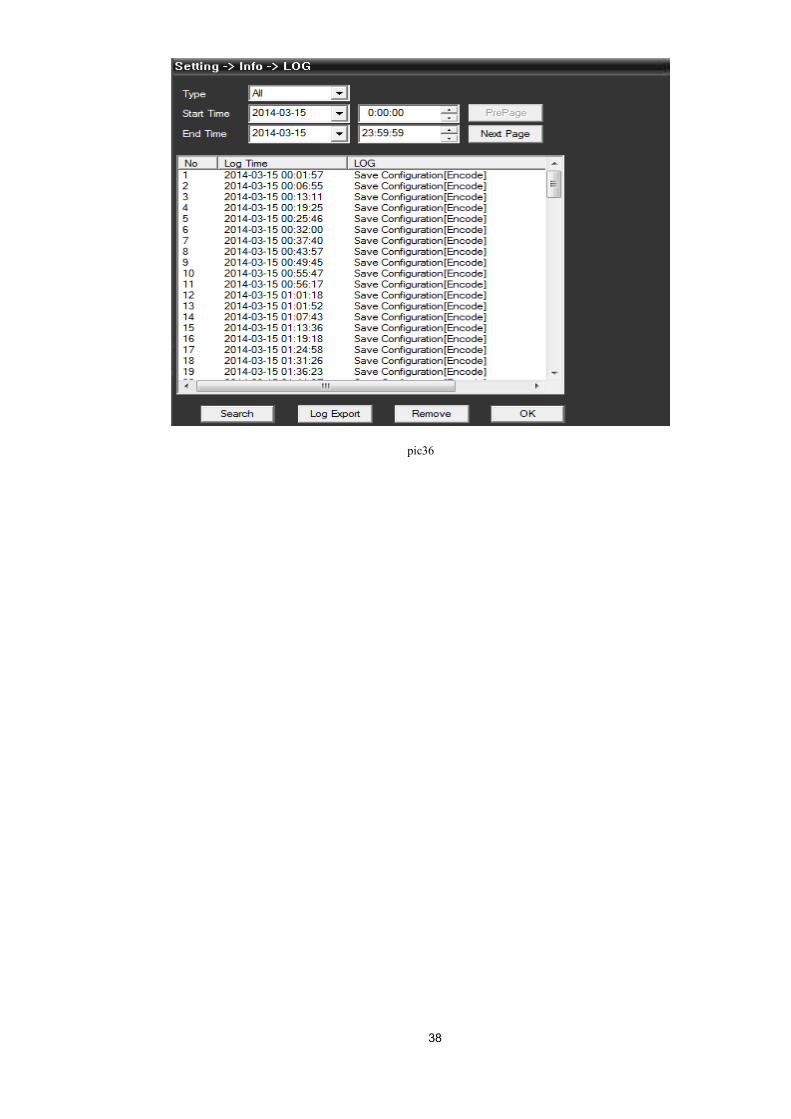
5.5Local Log User could search menu operation log, alarm log and other logs by time, see pic36:
38
pic36
39
Chapter 6 Record
In menu area, click “record”, the record interface will show at operation area.
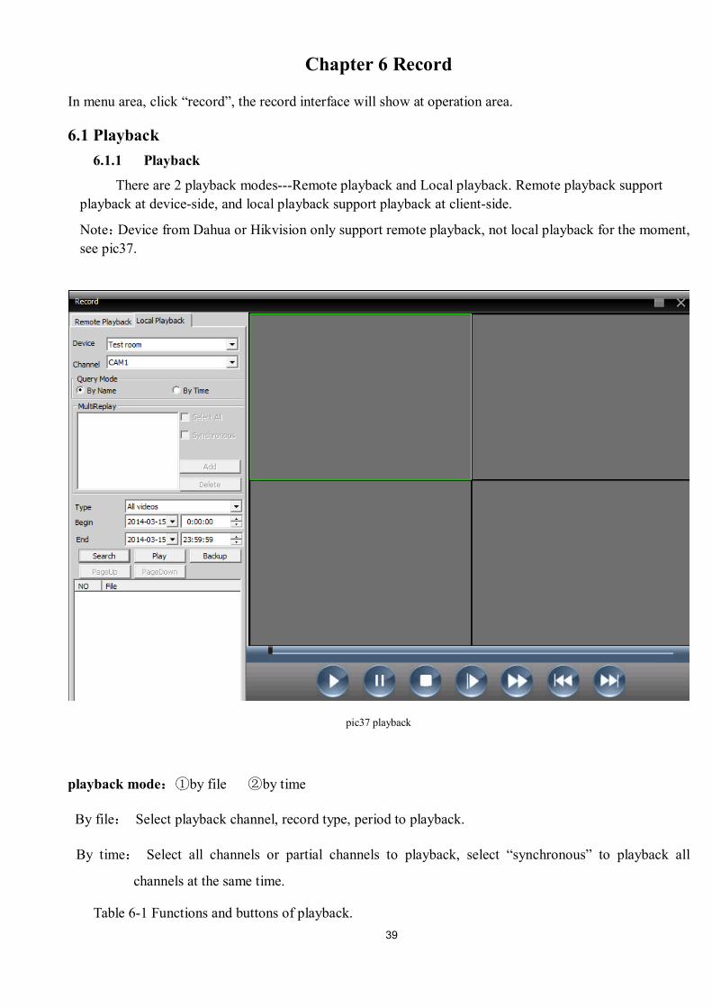
6.1 Playback 6.1.1 Playback
There are 2 playback modes---Remote playback and Local playback. Remote playback support playback at device-side, and local playback support playback at client-side.
Note:Device from Dahua or Hikvision only support remote playback, not local playback for the moment, see pic37.
pic37 playback
playback mode:①by file ②by time
By file: Select playback channel, record type, period to playback.
By time: Select all channels or partial channels to playback, select “synchronous” to playback all
channels at the same time.
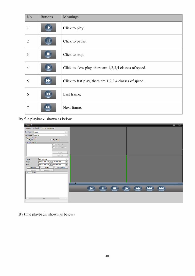
Table 6-1 Functions and buttons of playback.
40
No. Buttons Meanings
1
Click to play.
2
Click to pause.
3
Click to stop.
4
Click to slow play, there are 1,2,3,4 classes of speed.
5
Click to fast play, there are 1,2,3,4 classes of speed.
6
Last frame.
7
Next frame.
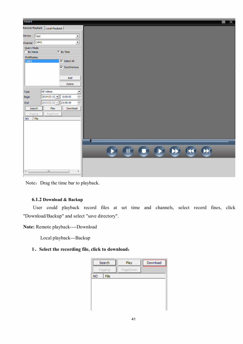
By file playback, shown as below:
By time playback, shown as below:
41
Note:Drag the time bar to playback.
6.1.2 Download & Backup User could playback record files at set time and channels, select record fines, click
"Download/Backup" and select "save directory".
Note: Remote playback----Download
Local playback---Backup
1、Select the recording file, click to download:
42
2、Pop up a window, select record format.
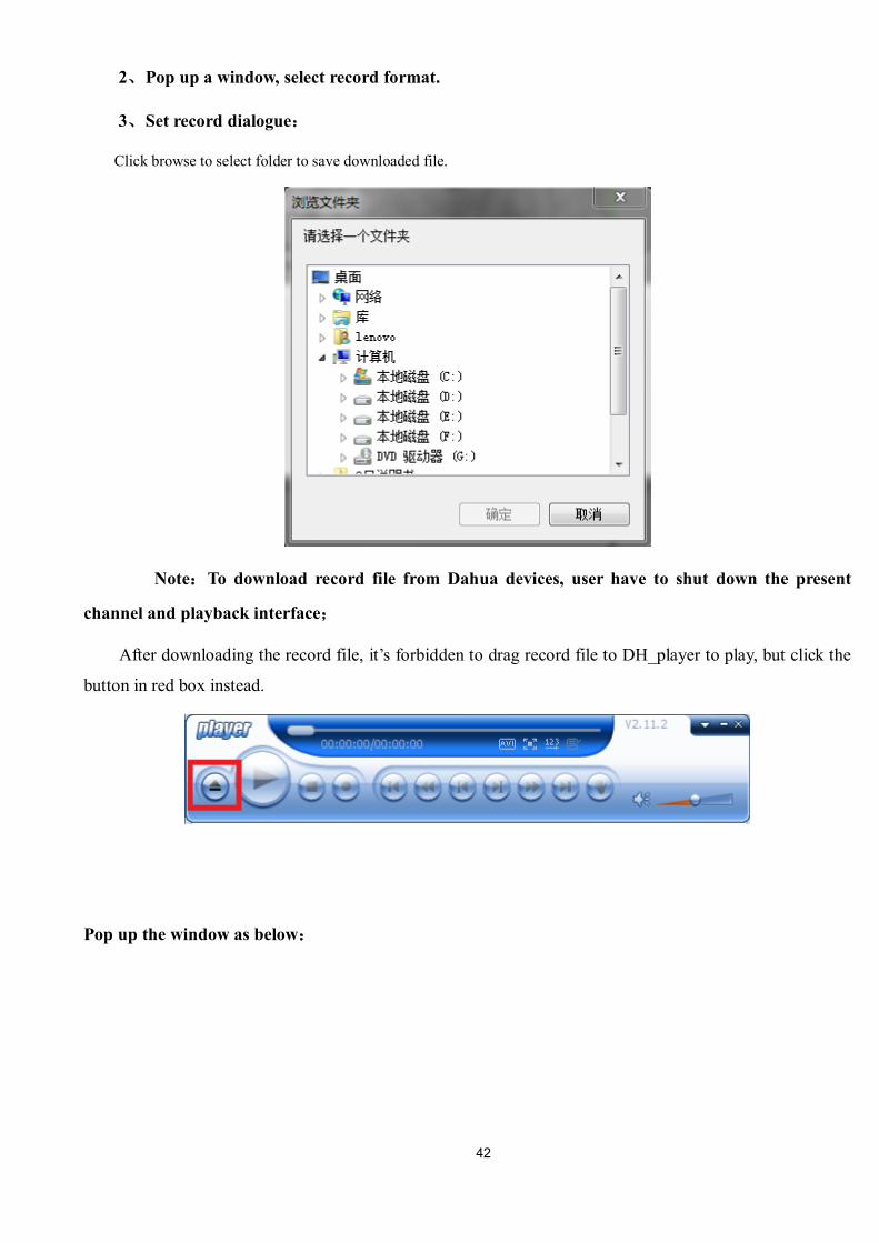
3、Set record dialogue:
Click browse to select folder to save downloaded file.
Note:To download record file from Dahua devices, user have to shut down the present
channel and playback interface;
After downloading the record file, it’s forbidden to drag record file to DH_player to play, but click the
button in red box instead.
Pop up the window as below:
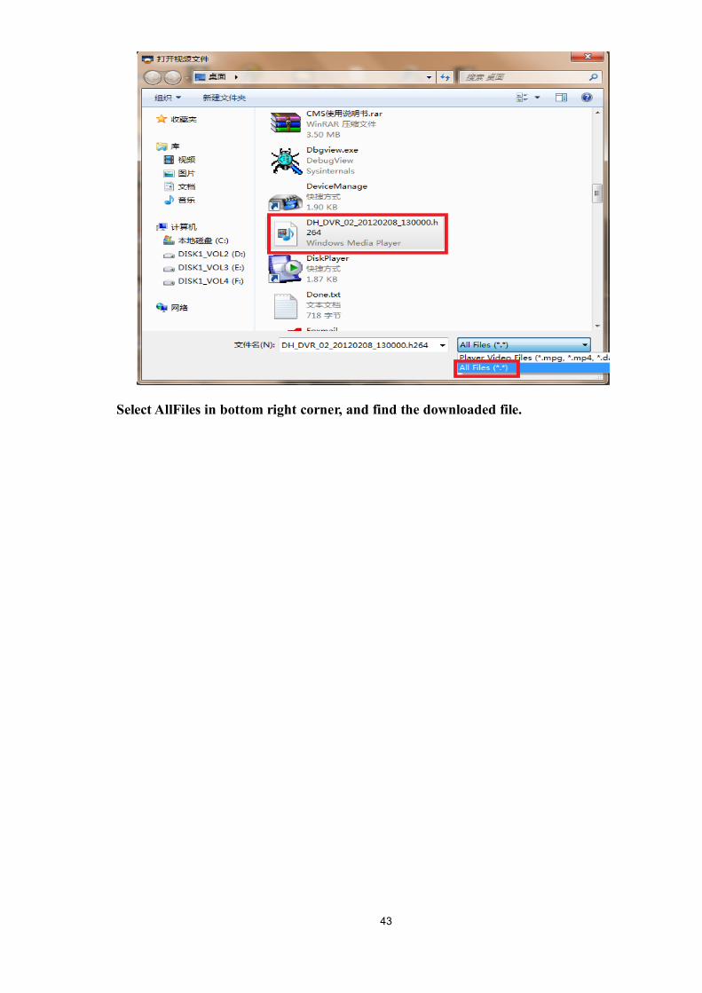
43
Select AllFiles in bottom right corner, and find the downloaded file.
44
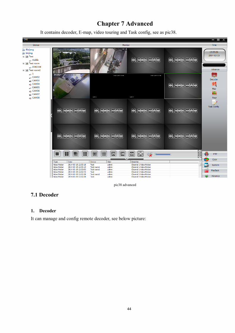
Chapter 7 Advanced It contains decoder, E-map, video touring and Task config, see as pic38.
pic38 advanced
7.1 Decoder
1. Decoder It can manage and config remote decoder, see below picture:
45
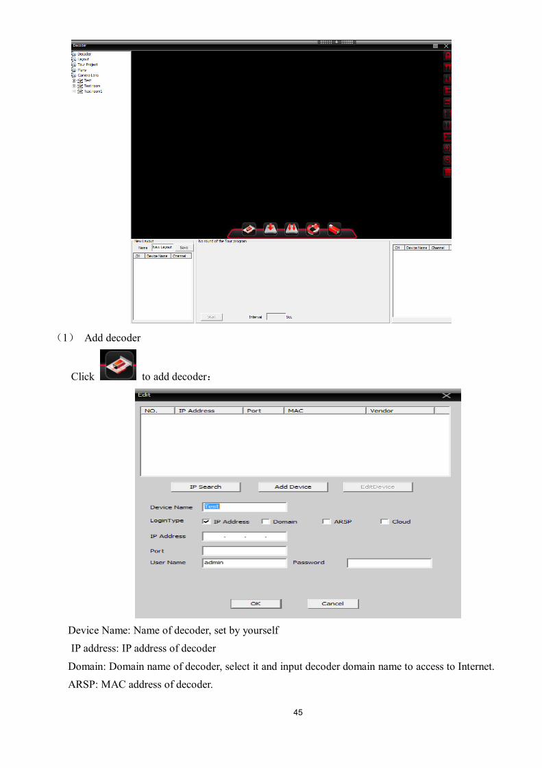
(1) Add decoder
Click to add decoder:
Device Name: Name of decoder, set by yourself IP address: IP address of decoder
Domain: Domain name of decoder, select it and input decoder domain name to access to Internet. ARSP: MAC address of decoder.
46
Cloud: SerialNo of decoder.
Port: TCP port, default is 34567 User Name: Login name of decoder, default is admin
Password: Password of decoder, default is null.
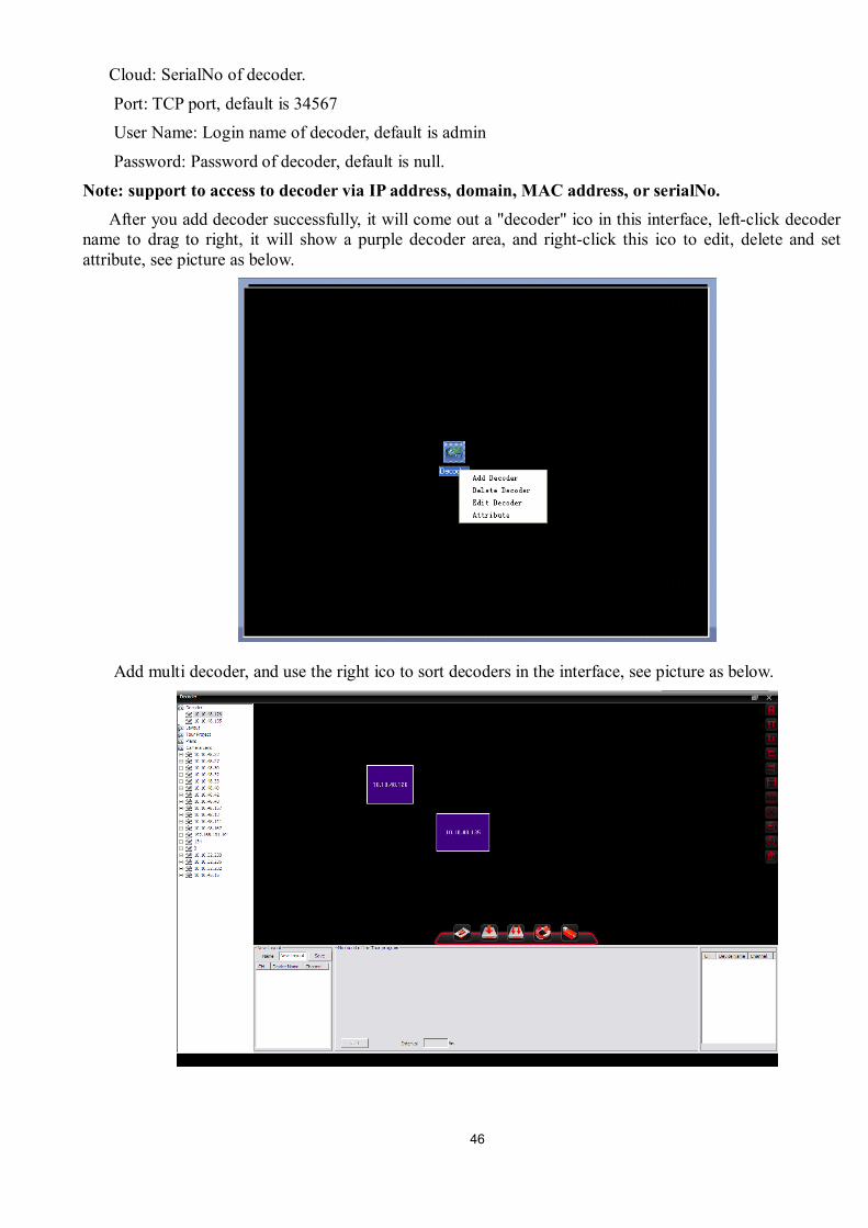
Note: support to access to decoder via IP address, domain, MAC address, or serialNo. After you add decoder successfully, it will come out a "decoder" ico in this interface, left-click decoder
name to drag to right, it will show a purple decoder area, and right-click this ico to edit, delete and set attribute, see picture as below.
Add multi decoder, and use the right ico to sort decoders in the interface, see picture as below.
47
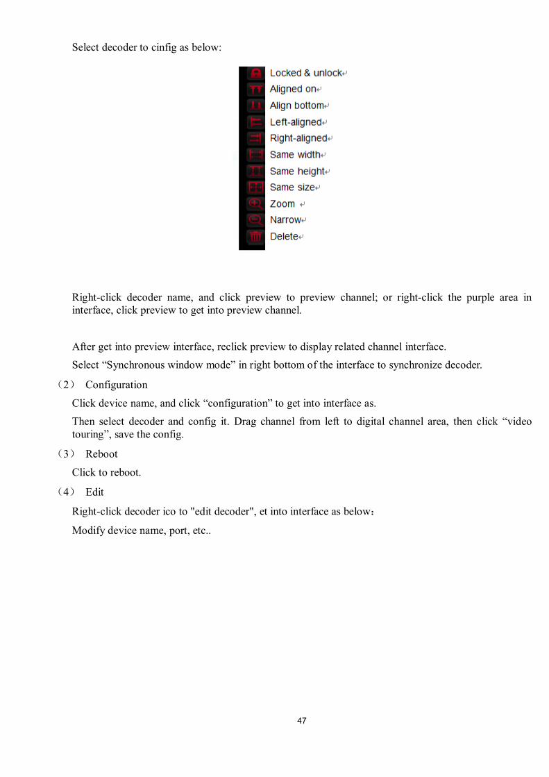
Select decoder to cinfig as below:
Right-click decoder name, and click preview to preview channel; or right-click the purple area in interface, click preview to get into preview channel.
After get into preview interface, reclick preview to display related channel interface. Select “Synchronous window mode” in right bottom of the interface to synchronize decoder.
(2) Configuration
Click device name, and click “configuration” to get into interface as. Then select decoder and config it. Drag channel from left to digital channel area, then click “video touring”, save the config.
(3) Reboot
Click to reboot.
(4) Edit
Right-click decoder ico to "edit decoder", et into interface as below:
Modify device name, port, etc..
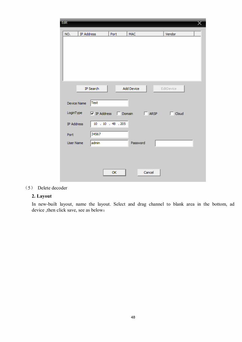
48
(5) Delete decoder
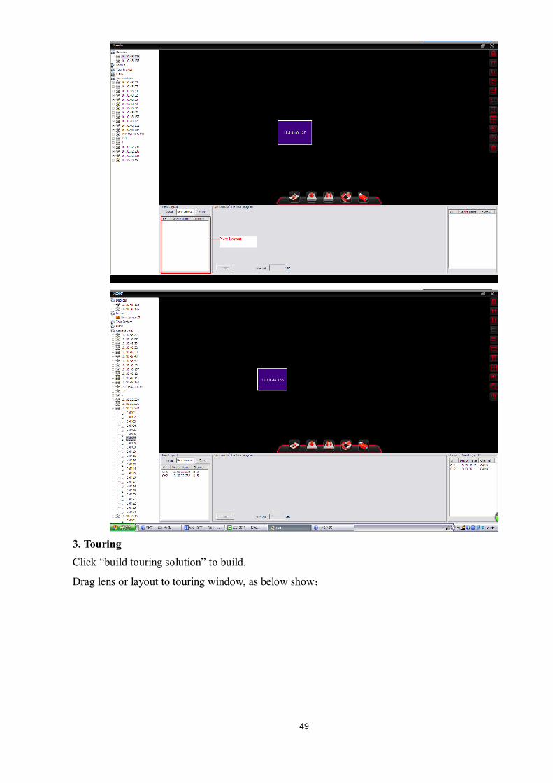
2. Layout In new-built layout, name the layout. Select and drag channel to blank area in the bottom, ad device ,then click save, see as below:
49
3. Touring Click “build touring solution” to build.
Drag lens or layout to touring window, as below show:
50
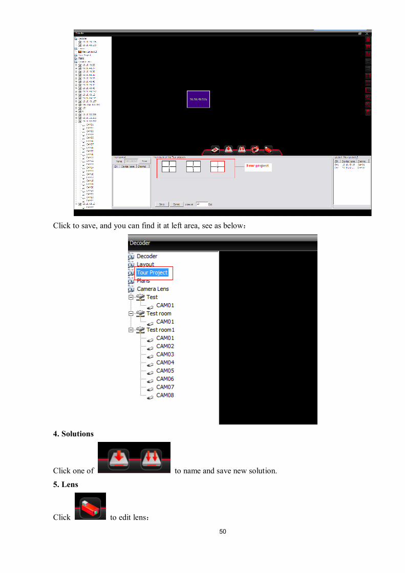
Click to save, and you can find it at left area, see as below:
4. Solutions
Click one of to name and save new solution.
5. Lens
Click to edit lens:
51
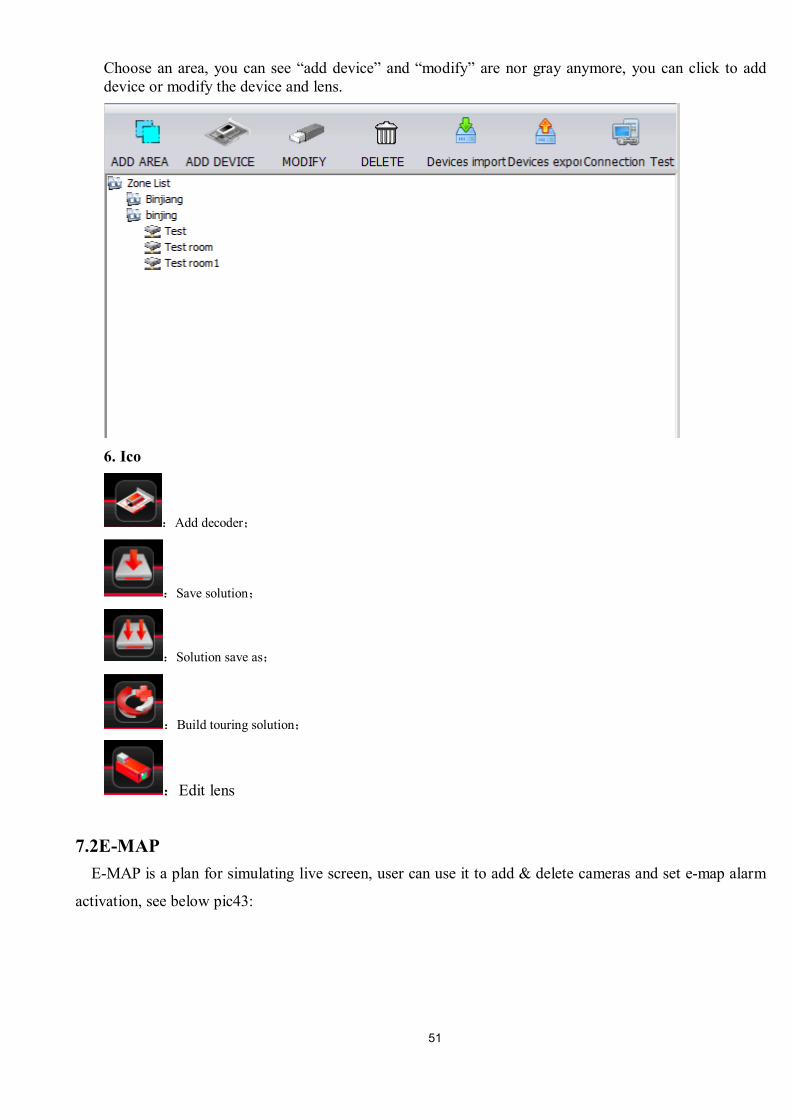
Choose an area, you can see “add device” and “modify” are nor gray anymore, you can click to add device or modify the device and lens.
6. Ico
:Add decoder;
:Save solution;
:Solution save as;
:Build touring solution;
:Edit lens
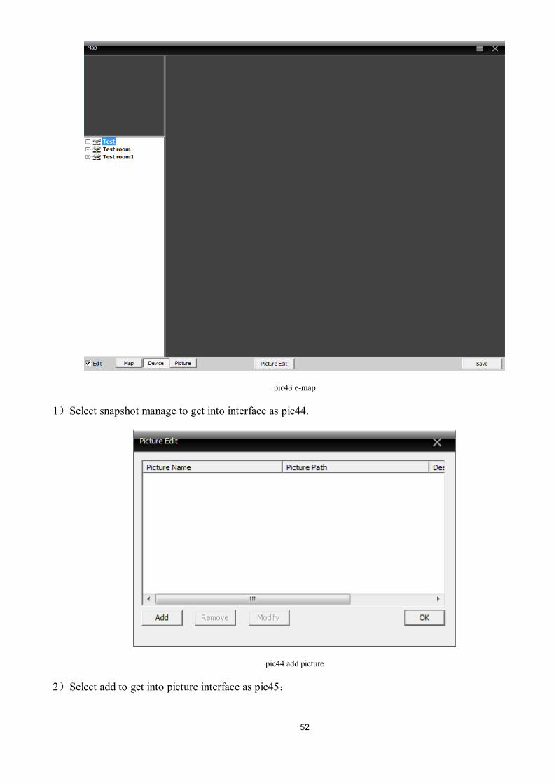
7.2E-MAP E-MAP is a plan for simulating live screen, user can use it to add & delete cameras and set e-map alarm
activation, see below pic43:
52
pic43 e-map
1)Select snapshot manage to get into interface as pic44.
pic44 add picture
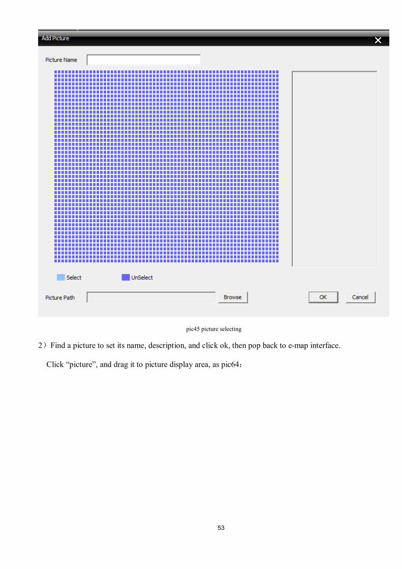
2)Select add to get into picture interface as pic45:
53
pic45 picture selecting
2)Find a picture to set its name, description, and click ok, then pop back to e-map interface.
Click “picture”, and drag it to picture display area, as pic64:
54
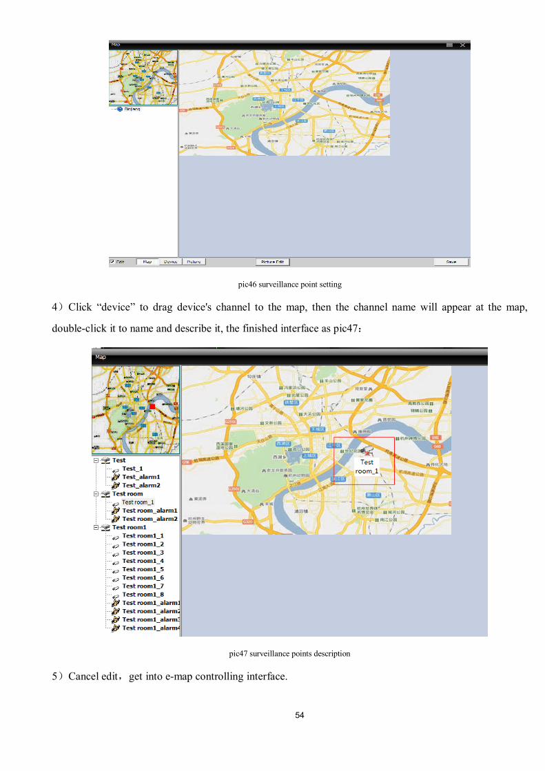
pic46 surveillance point setting
4)Click “device” to drag device's channel to the map, then the channel name will appear at the map,
double-click it to name and describe it, the finished interface as pic47:
pic47 surveillance points description
5)Cancel edit,get into e-map controlling interface.
55
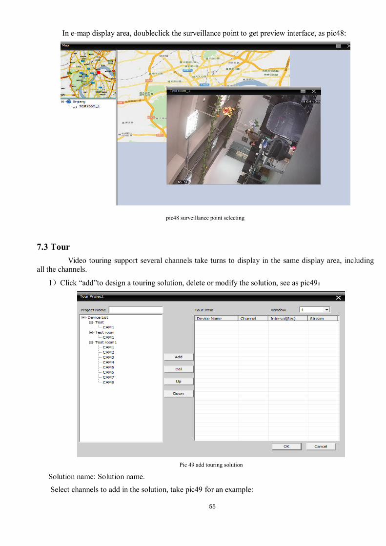
In e-map display area, doubleclick the surveillance point to get preview interface, as pic48:
pic48 surveillance point selecting
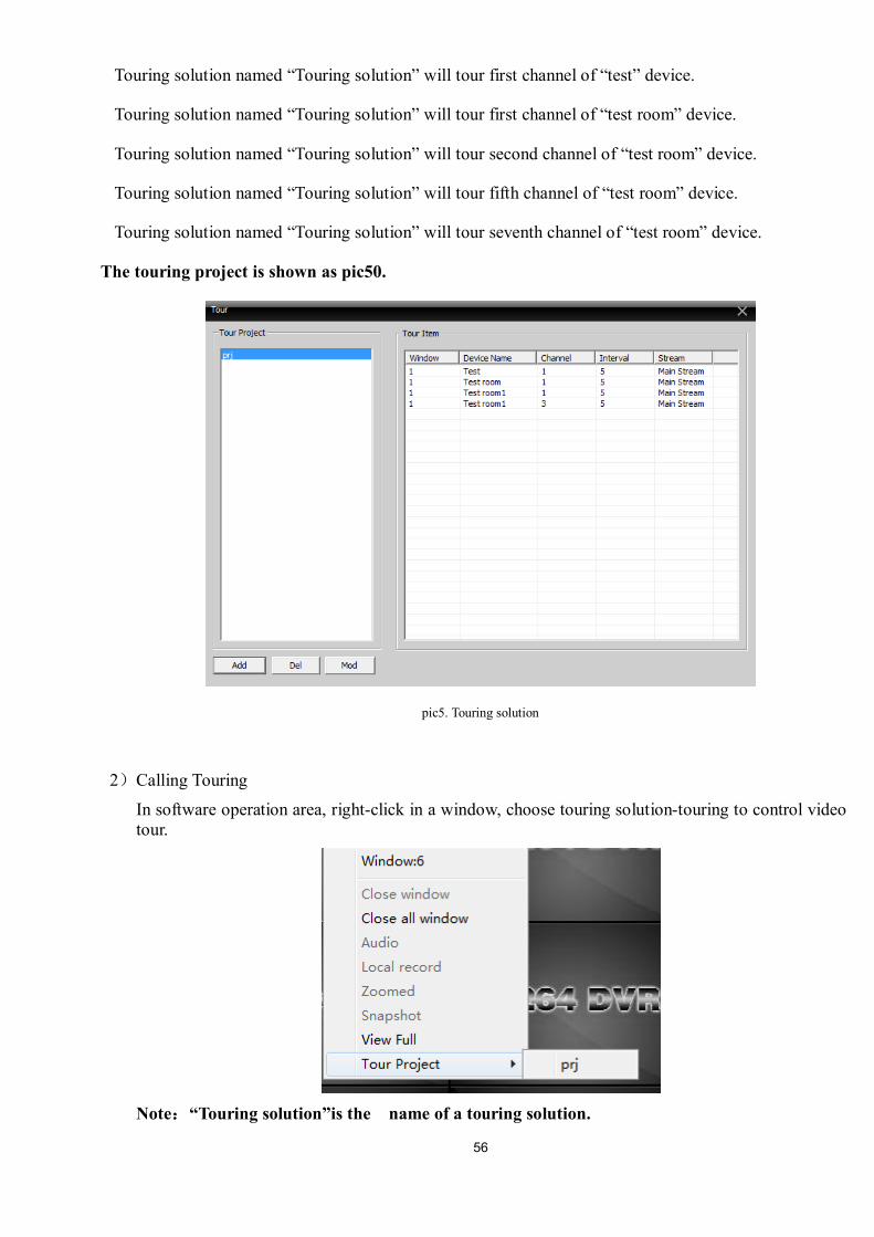
7.3 Tour Video touring support several channels take turns to display in the same display area, including
all the channels.
1)Click “add”to design a touring solution, delete or modify the solution, see as pic49:
Pic 49 add touring solution
Solution name: Solution name.
Select channels to add in the solution, take pic49 for an example:
56
Touring solution named “Touring solution” will tour first channel of “test” device.
Touring solution named “Touring solution” will tour first channel of “test room” device.
Touring solution named “Touring solution” will tour second channel of “test room” device.
Touring solution named “Touring solution” will tour fifth channel of “test room” device.
Touring solution named “Touring solution” will tour seventh channel of “test room” device.
The touring project is shown as pic50.
pic5. Touring solution
2)Calling Touring
In software operation area, right-click in a window, choose touring solution-touring to control video tour.
Note:“Touring solution”is the name of a touring solution.
57
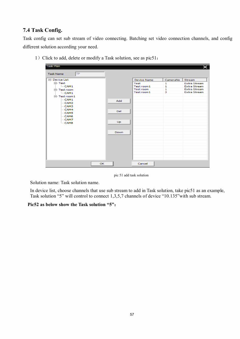
7.4 Task Config. Task config can set sub stream of video connecting. Batching set video connection channels, and config
different solution according your need.
1)Click to add, delete or modify a Task solution, see as pic51:
pic 51 add task solution
Solution name: Task solution name. In device list, choose channels that use sub stream to add in Task solution, take pic51 as an example, Task solution “5” will control to connect 1,3,5,7 channels of device “10.135”with sub stream.
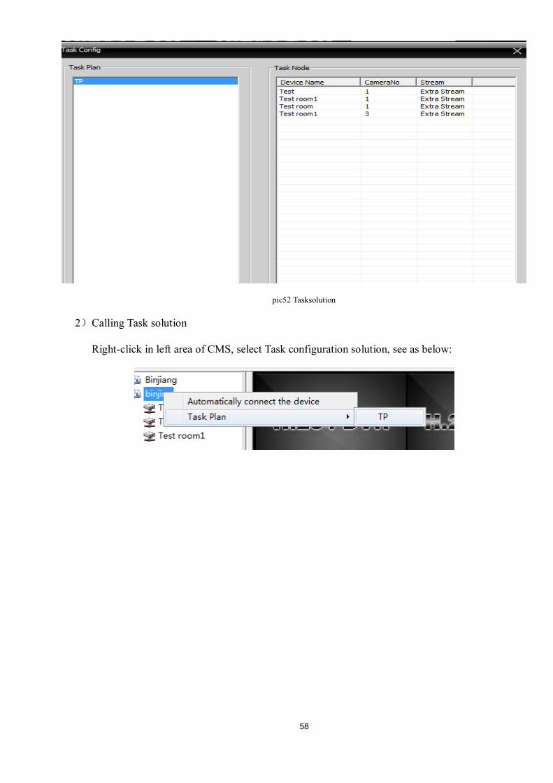
Pic52 as below show the Task solution “5”:
58
pic52 Tasksolution
2)Calling Task solution
Right-click in left area of CMS, select Task configuration solution, see as below:
59
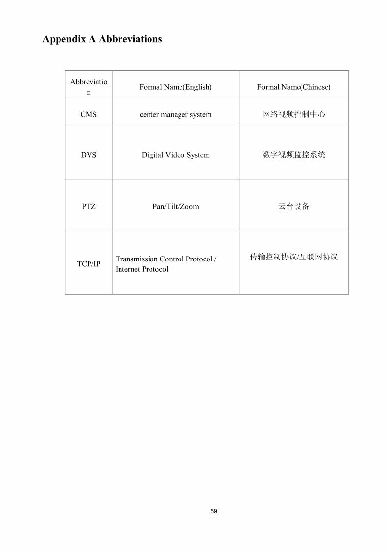
Appendix A Abbreviations
Abbreviation Formal Name(English) Formal Name(Chinese)
CMS center manager system 网络视频控制中心
DVS Digital Video System 数字视频监控系统
PTZ Pan/Tilt/Zoom 云台设备
TCP/IP Transmission Control Protocol / Internet Protocol
传输控制协议/互联网协议
60
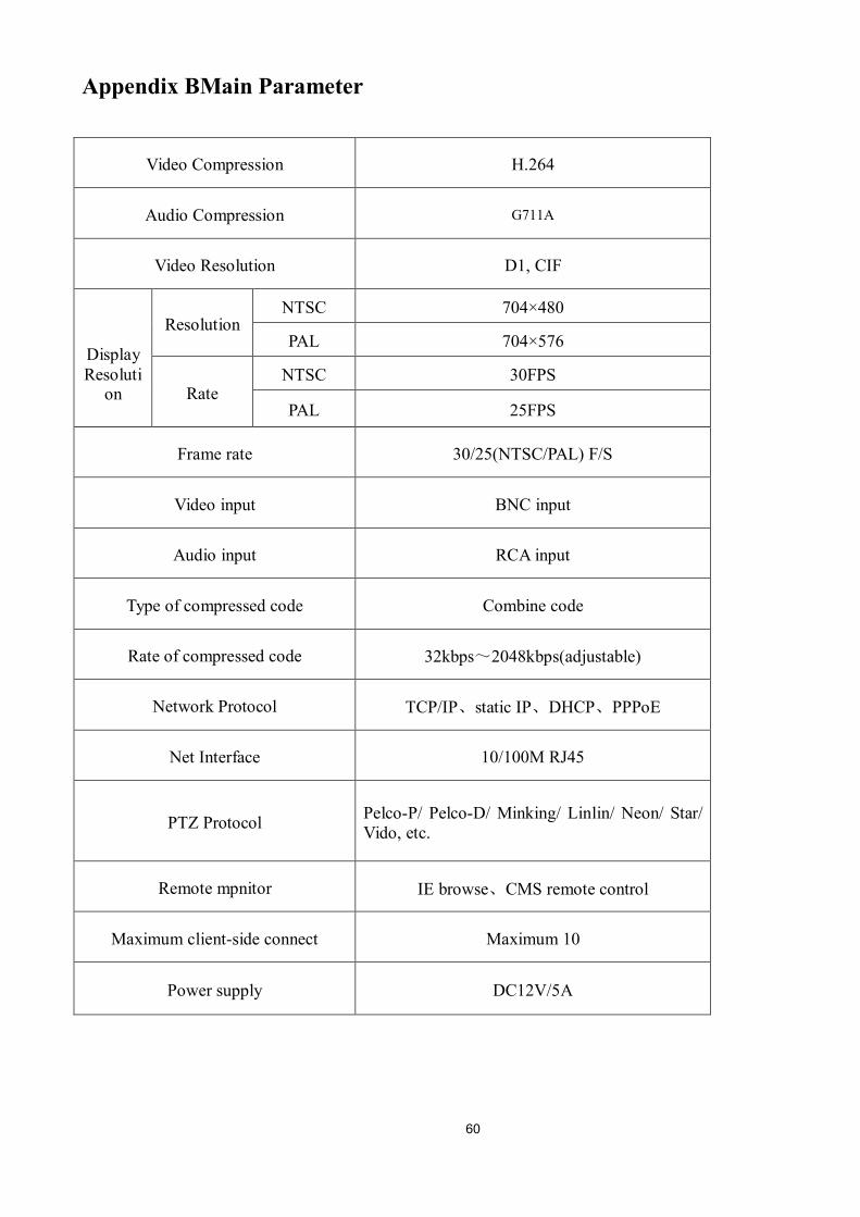
Appendix BMain Parameter
Video Compression H.264
Audio Compression G711A
Video Resolution D1, CIF
Display Resoluti
on
Resolution NTSC 704×480
PAL 704×576
Rate NTSC 30FPS
PAL 25FPS
Frame rate 30/25(NTSC/PAL) F/S
Video input BNC input
Audio input RCA input
Type of compressed code Combine code
Rate of compressed code 32kbps~2048kbps(adjustable)
Network Protocol TCP/IP、static IP、DHCP、PPPoE
Net Interface 10/100M RJ45
PTZ Protocol Pelco-P/ Pelco-D/ Minking/ Linlin/ Neon/ Star/ Vido, etc.
Remote mpnitor IE browse、CMS remote control
Maximum client-side connect Maximum 10
Power supply DC12V/5A