Embed Size (px)
Citation preview

CMB24D DMX
24 Channel DC Controller
User Manual June 1, 2013
V1.00 Copyright © Light O Rama, Inc. 2013

Table of Contents
Introduction .............................................................. 4 What’s in the Box ..................................................... 5 Applications ............................................................. 5 Metal Tab Transistor Consideration ......................... 6 Installing Heat Sinks ................................................ 6 Quick Start Guide .................................................... 7 Hardware Fundamentals ......................................... 8
LOR/DMX Network Selection Jumpers ................ 8 Setting the Unit ID (and DMX address) ................ 8 Reset the CMB24D .............................................. 9 Data Cable Connections ...................................... 9
Connecting to PC ............................................. 9 Connecting to Other Controllers ....................... 9
Status LED ........................................................... 9 Auxiliary Power Input Barrel ............................... 10 Channel Power Inputs ........................................ 10 Channel Power Outputs ..................................... 11 Input Header (JP4) ............................................. 11 Current Handling Considerations ....................... 12 Nitty-Gritty .......................................................... 13
Connecting Controller-to-PC Data Cable ............... 13 Testing the CMB24D ............................................. 14 Designing and Playing a Sequence ....................... 15 Stand Alone Operation .......................................... 15 Troubleshooting ..................................................... 16
Erratic Behavior When Lights Turned On ........... 16 Refresh in the HWU fails to find the controller .... 17 AutoConfigure fails to find COM port .................. 17
Updating Controller Firmware ................................ 18 DIP Switch Address Settings ................................. 20 Specifications......................................................... 27
Introduction The CMB24D is a member of the Component line of Light-O-Rama (LOR) products. It was designed to control DC lighting or any DC device that will tolerate a PWM modulated voltage. It is a microprocessor based, intelligent controller that can perform a number of lighting effects including dimming, fading, shimmering and twinkling. It can be daisy-chained with any mix of LOR controllers up to the maximum of 240 controllers. The CMB24D automatically detects and obeys either LOR protocol or DMX protocol. It can be used with the LOR Windows Showtime Software Suite. This software allows you to design your sequences (sequences are lighting control command sets), arrange your sequences into shows and to schedule and play your shows. To allow your PC to communicate with this controller, you will need one of Light O Rama’s RS485 adapters. When you purchase the Generic Starter Package, you get the LOR Showtime Software, a 10’ Cat5 network cable and a choice of RS485 adapters. Choose the adapter appropriate for your PC/laptop. The RS485 adapter will allow you to connect your PC/laptop via the Cat5 cable to your DC controller. As with all LOR controllers, this controller is field firmware upgradeable so you are guaranteed compatibility with future LOR products. This controller has Common Anode (common positive) outputs. This means that the positive voltage is applied to all outputs continuously and the negative is switched.
CMB24D
5
Caution: Although most applications for this product use low voltages, this product may be used with dangerous DC voltages. It is important that you have an understanding of electrical wiring.
What’s in the Box The CMB24D comes with a user manual. The latest version of this manual is also available at www.lightorama.com ► Support ► User Manuals ► CMB24D User Manual.
Applications The CMB24D can be controlled by another LOR controller or, if you would like audio coordinated with the controller, one of the LOR Show Directors or a Windows PC. The CMB24D can also run a standalone sequence. This means a set of lighting (or other device) commands created using the Windows Showtime Software can be downloaded into the CMB24D. The CMB24D can use these internally stored commands to direct itself and additional controllers. See the Standalone Operation section for more information. The low voltage (safety) and standalone capabilities allow the CMB24D to be deployed in a myriad of remote applications with no additional hardware being required. For example:
General LED lighting (spot lights, etc.) Vehicle lighting (Bike, Car, Boat, etc.) Landscaping, pool and pond lighting DC Motors, solenoids, valves, relays
CMB24D
6
Metal Tab Transistor Consideration CMB24D boards have transistors with metal tabs. Heat sinks are not required if the current draw per channel is 4 amps or less. The metal tab of the transistor is electrically hot and a TO-220 insulating kit (mica wafer and screw grommet) is required when mounting the transistors to metal heat sinks. Also, keep this fact in mind when using the board since it is possible to short out the metal tab transistors.
Installing Heat Sinks The CMB24D is not designed to easily attach external heat sinks. The transistors are mounted inside the edges of the board to make attachment of controlled devices easier since the screw terminals are on the outside edge of the board. A small amount of thermal compound is needed to facilitate the transfer of heat from the transistors to the heat sink. Remember to use a TO-220 insulating kit. Put a 1/8” x 1/4” dab of heat sink compound on the back surface of the transistor just below the screw hole. The mica wafer goes between the transistor and the heat sink. There must be heat sink compound on both sides of the wafer. Use a screw grommet to prevent the screw from connecting the transistor’s metal tab with the metal heat sink or use nylon screws. Put screws from the outside of the board through the end two transistors and then align the heat sink with these two screws and press it against the transistors.
CMB24D
7
Put a lock washer on each screw and a bolt, don’t tighten the bolts yet. Do the same for the other ten screws. Now tighten but don’t over-tighten the bolts. Repeat the process for the other channel bank.
Quick Start Guide This section assumes you have previous Light O Rama hardware experience. It provides the minimum needed to get the controller up and running. The assumptions here are 12 volt DC power (or greater) and loads not requiring heat sinks. Read the Hardware Fundamentals section for more detail. See Figure 1 in the Hardware Fundamentals section for circuit board locations. All DIP switches should be OFF except for switch 9. This will set the Unit ID to 01. Connect DC power to at least the Channels 1-12 Power Inputs. The Status LED should be blinking about twice/second. Connect a DC load to +v and the channel 1 power outputs. Connect the CMB24D to your network and fire up the Hardware Utility. The Status LED should go to steady on. Refresh the controllers, select this controller and use the Test Unit’s Operation section to exercise the lights.
CMB24D
8
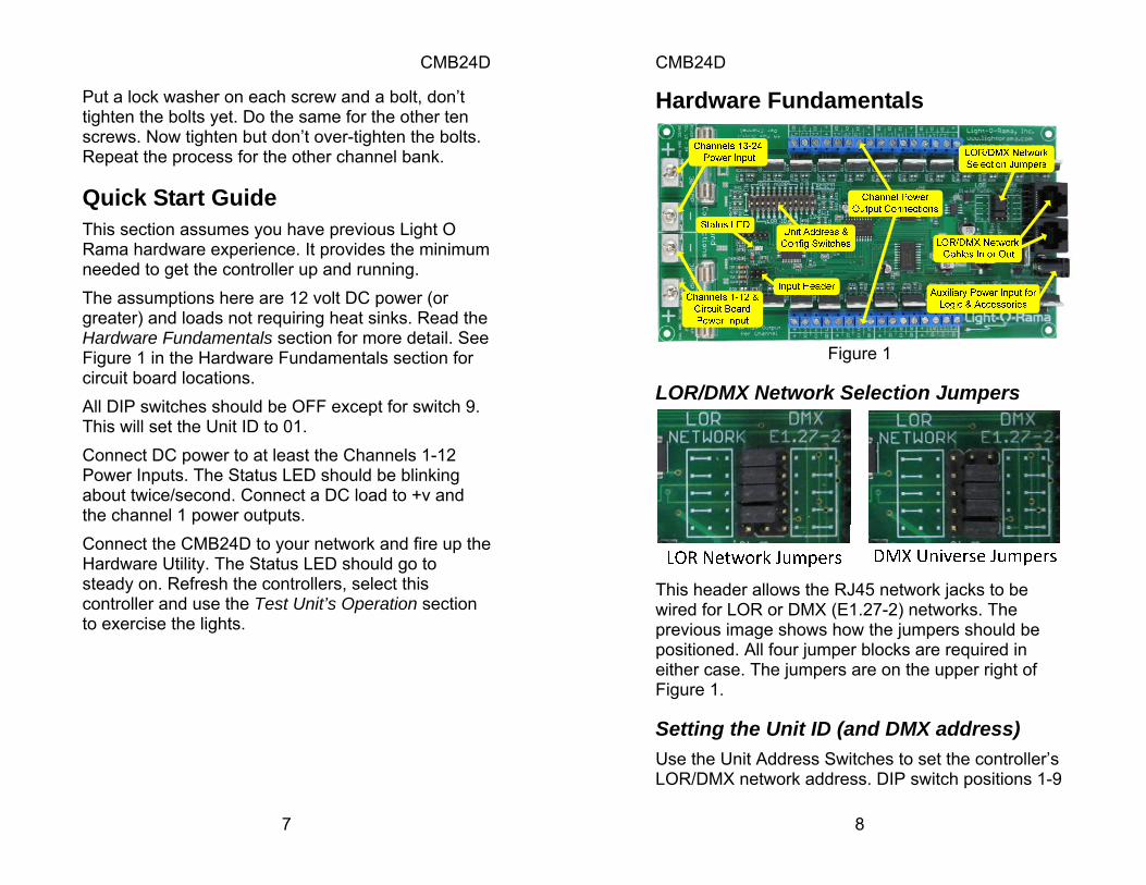
Hardware Fundamentals
Figure 1
LOR/DMX Network Selection Jumpers
This header allows the RJ45 network jacks to be wired for LOR or DMX (E1.27-2) networks. The previous image shows how the jumpers should be positioned. All four jumper blocks are required in either case. The jumpers are on the upper right of Figure 1.
Setting the Unit ID (and DMX address) Use the Unit Address Switches to set the controller’s LOR/DMX network address. DIP switch positions 1-9
CMB24D
9
set the address. Refer to the DIP Switch Address Settings section for the mapping of your desired LOR/DMX address to DIP switch settings. Legal LOR Network unit IDs are ‘01’ to ‘F0’ hexadecimal, in decimal that would be 1 to 240. Legal DMX Network start addresses are 1 to 511 decimal.
Reset the CMB24D To set all device parameters back to factory defaults and erase any stand-alone program, power the controller down, set DIP switch 12 to ON and power it up. The Status LED will flash quickly. Power the controller down and turn DIP switch 12 off.
Data Cable Connections The two LOR/DMX network jacks are RJ45s.
Connecting to PC To use Cat5 LAN cable to connect your controller to the PC RS485 adapter, plug one end of the data cable into the adapter and the other end into either of the network jacks.
Connecting to Other Controllers To use Cat5 LAN cable to connect your controller to another controller, go from either network jack on one controller to either RJ45 network jack on the other controller.
Status LED LED blinking approximately twice/second: The controller has booted correctly and is waiting for
CMB24D
10
commands. The controller is not connected to an active Light O Rama network or DMX universe. LED is on solid: The controller is connected to an active network (is receiving the heartbeat and commands from a PC, a Show Director, another controller or DMX source.) LED blinks quickly: The controller is resetting because DIP switch 12 is on. LED blinks on for a long pulse and off for a short pulse: The controller firmware needs to be downloaded. See the Updating Controller Firmware section.
Auxiliary Power Input Barrel Use a 12 to 24 volt DC, 300 milliamp external power supply here if the power input to channels 1-12 is less than 12 volts DC. If the main power input to channels 1-12 is 12 volts DC or greater, the microprocessor and accessory power supplies will be derived from it. The center pin of the power barrel is positive.
Channel Power Inputs Bank power input connections are made with lugs. Figure 1 shows the two channel bank power inputs on the left. The bottom power input is for channels 1 to 12. If this input is at 12 volts DC or higher, it will automatically be used to power the circuit board logic and accessories (like wireless.) If the DC power to channels’ 1-12 input is less than 12 volts DC, see the Auxiliary Power Input Barrel section.
CMB24D
11
You may use different voltages on channel banks 1-12 and 13-24. The ground between the two channel banks is common, but you must use both grounds when using the board to switch more than 30 amps.
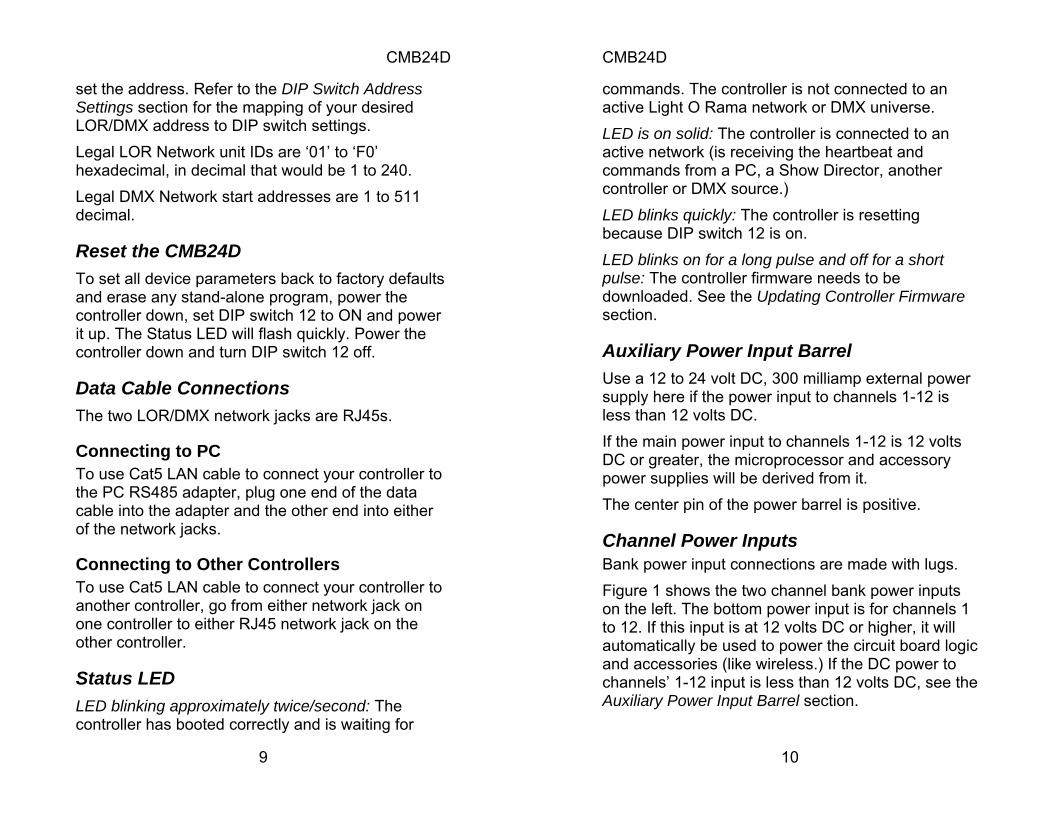
Channel Power Outputs
Figure 2
All output connections are made with screw terminals. Figure 2 shows the power output connections for channels 1 through 6. The silk-screening on the board labels each channel (negative connection) and their shared positive connections. Remember that DC loads can be polarity sensitive. If you find that LEDs connected to the outputs do not light, try swapping the positive and negative connections.
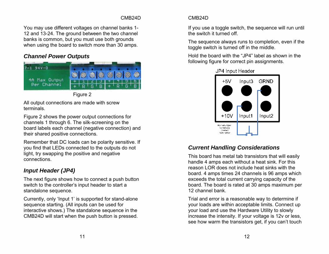
Input Header (JP4) The next figure shows how to connect a push button switch to the controller’s input header to start a standalone sequence. Currently, only ‘Input 1’ is supported for stand-alone sequence starting. (All inputs can be used for interactive shows.) The standalone sequence in the CMB24D will start when the push button is pressed.
CMB24D
12
If you use a toggle switch, the sequence will run until the switch it turned off. The sequence always runs to completion, even if the toggle switch is turned off in the middle. Hold the board with the “JP4” label as shown in the following figure for correct pin assignments.
Current Handling Considerations This board has metal tab transistors that will easily handle 4 amps each without a heat sink. For this reason LOR does not include heat sinks with the board. 4 amps times 24 channels is 96 amps which exceeds the total current carrying capacity of the board. The board is rated at 30 amps maximum per 12 channel bank. Trial and error is a reasonable way to determine if your loads are within acceptable limits. Connect up your load and use the Hardware Utility to slowly increase the intensity. If your voltage is 12v or less, see how warm the transistors get, if you can’t touch
CMB24D
13
it, it needs a heat sink. If your voltage is higher where it might be dangerous to touch the metal tab of the transistor, use a thermometer.
Nitty-Gritty This section is for technical types who are not sure whether their application would be a good match for the CMB24D. There are two banks of MOSFETs, bank 1 for output channels 1 to 12, and bank 2 for output channels 13 to 24. The positive outputs of a bank are all tied together (common anode) and connected through their fuse to the positive power input. A MOSFET is used to ground the load connected to its channel, so positive power is always present at the load. The MOSFETs are Pulse Width Modulated at 400 Hz. 1/400th second = 2.5 milliseconds. There are 240 possible intensities. This means that in each 400th of a second, the grounding pulse is somewhere between 0/240*2.5 ms (off) and 240/240*2.5ms (full on.)
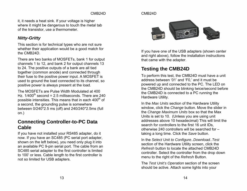
Connecting Controller-to-PC Data Cable If you have not installed your RS485 adapter, do it now. If you have an SC485 (PC serial port adapter, shown on the left below), you need only plug it into an available PC 9-pin serial port. The cable from an SC485 serial adapter to the first controller is limited to 100’ or less. Cable length to the first controller is not so limited for USB adapters.
CMB24D
14
If you have one of the USB adapters (shown center and right above), follow the installation instructions that came with the adapter.
Testing the CMB24D To perform this test, the CMB24D must have a unit address between ‘01’ and ‘F0,’ and it must be powered up and connected to the PC. The LED on the CMB24D should be blinking twice/second before the CMB24D is connected to a PC running the Hardware Utility. In the Max Units section of the Hardware Utility window, click the Change button. Move the slider in the Change Maximum Units box so that the Max Units is set to 10. (Unless you are using unit addresses above 10 hexadecimal) This will limit the search for controllers to the first 16 unit IDs, otherwise 240 controllers will be searched for – taking a long time. Click the Save button. In the Select Unit to Configure..Download..Test section of the Hardware Utility screen, click the Refresh button to locate the attached CMB24D controller. Select the controller from the drop down menu to the right of the Refresh Button. The Test Unit’s Operation section of the screen should be active. Attach some lights into your
CMB24D
15
controller and use the sliders and buttons in this section to test your controller.
Designing and Playing a Sequence Lighting commands for your shows are called Sequences and are designed and implemented using the Sequence Editor Windows software. Stop the Hardware Utility. You will not be able to command your controller from the Sequence Editor if the Hardware Utility is running. Only one program may use the RS485 adapter at a time to talk to Light O Rama controllers. There are Quick Start Guides for creating animation (non-musical) and musical sequences, Flash Tutorials and much more at: www.lightorama.com ► Support ► User Manuals The following Wiki is also an excellent source of information on all things Light-O-Rama: www.lorwiki.com There is also a very active and helpful Light-O-Rama user community: www.lightorama.com ► Forums
Stand Alone Operation An animation sequence (sequence with no accompanying audio) can be downloaded in the CMB24D. This sequence can contain approximately 10,000 commands. These commands can also be for controllers other than this CMB24D, so this controller can direct a network of controllers. There is
CMB24D
16
no restriction on the types of controllers in this network. The sequence is designed and tested using the Showtime Software Sequence Editor. When you are happy with the sequence, save it and stop the Sequence Editor. Start the Hardware Utility and click the Refresh button to find the CMB24D. Use the drop down menu next to the Refresh button to select the CMB24D. Click the Standalone button at the bottom of the window. Select one of “Run when power is on,” “Input (norm open switch)” or “Input (norm closed switch.)” Click the Send Trigger info to Unit button. Finally, Use the Open button to browse to your sequence and click the Download button.
Troubleshooting
Erratic Behavior When Lights Turned On The most likely cause is insufficient power. If the CMB24D is being powered by the same power supply as the lights/loads, turning them on may cause a voltage drop and crash the microcomputer. If you suspect that your power supply may not be up to the task, see the Auxiliary Power Input Barrel section. This section will explain how to power the card logic independently of the loads.
CMB24D
17
Refresh in the HWU fails to find the controller Make sure the LOR/DMX Network Selection Jumpers are in the LOR position. See the LOR/DMX Network Selection Jumpers section. Make sure the Unit ID switches are set to a legal LOR unit ID. See the Setting the Unit ID (and DMX address) section. Make sure the Status LED is on steady when the controller is connected to the PC running the Hardware Utility, otherwise you may have selected the wrong communications port or there is a problem with your RS485 adapter or cabling.
AutoConfigure fails to find COM port Make sure the LOR/DMX Network Selection Jumpers are in the LOR position. Make sure the Unit ID switches are set to a legal LOR unit ID. See previous section. If the COM port is not detected, you can manually select it from the drop down list. If you are not sure which COM port is the RS485 adapter and you have a USB adapter, stop the Hardware Utility, disconnect the USB adapter from the PC and start the Hardware Utility. Use the Manual Select drop-down on the upper left to see which comm ports you have. Then stop the Hardware Utility, plug in the USB adapter, wait for it to install and start the Hardware Utility. The drop-down should show a new comm port, select it.
CMB24D
18
If you are not sure which COM port is the RS485 adapter and you have a serial port RS485 adapter, you will have to consult your PC’s documentation; it is normally COM1, COM2 or COM3.
Updating Controller Firmware Periodically, Light-O-Rama will distribute new firmware for the CMB24D. If you believe you need updated firmware, use the Hardware Utility to determine your current firmware version. Use the Refresh button to find your controller and check its firmware version. The drop-down menu to the right of the Refresh button will be filled in with the attached controllers. The right part of the controller name in this drop-down is the current firmware version. If the controller type or firmware version is not present, get the latest software that your license permits from www.lightorama.com ► Software. Run the program downloaded to install the software and devices text file. Retry the Refresh operation. The latest firmware can be found by going to www.lightorama.com ► Support ► Firmware. Find your controller type and roll the mouse over the Firmware button – look at the bar in the lower left of the browser window. It will show the name of the firmware file. The file name contains the version at the end. If the version number is greater than what you saw in the Hardware Utility, new firmware is available. Click the Firmware button to download the firmware installer to your PC – remember where you put it. To load new firmware, use a data cable (not wireless) to connect the controller(s) to the PC. Start
CMB24D
19
the Hardware Utility and click the Refresh button to find your controller(s). Select the one you want to update from the drop-down menu to the right of the Refresh button. Click the Firmware button at the bottom of the window. In the Firmware section of the window, under Step 1 – Select Unit, select the unit listed above. Under Step 2 – Select Firmware File, use the Open button to browse to the firmware file you downloaded. Under Step 3 – Press Download Button click the Download button. Do not interrupt this process. Your controller will reboot after the download completes. You can click the Refresh button to see that the new firmware was loaded into your controller. Repeat this process for additional controllers.
CMB24D
20
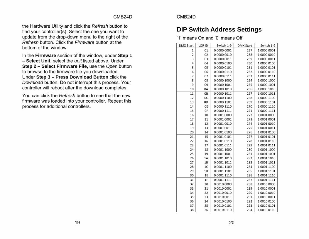
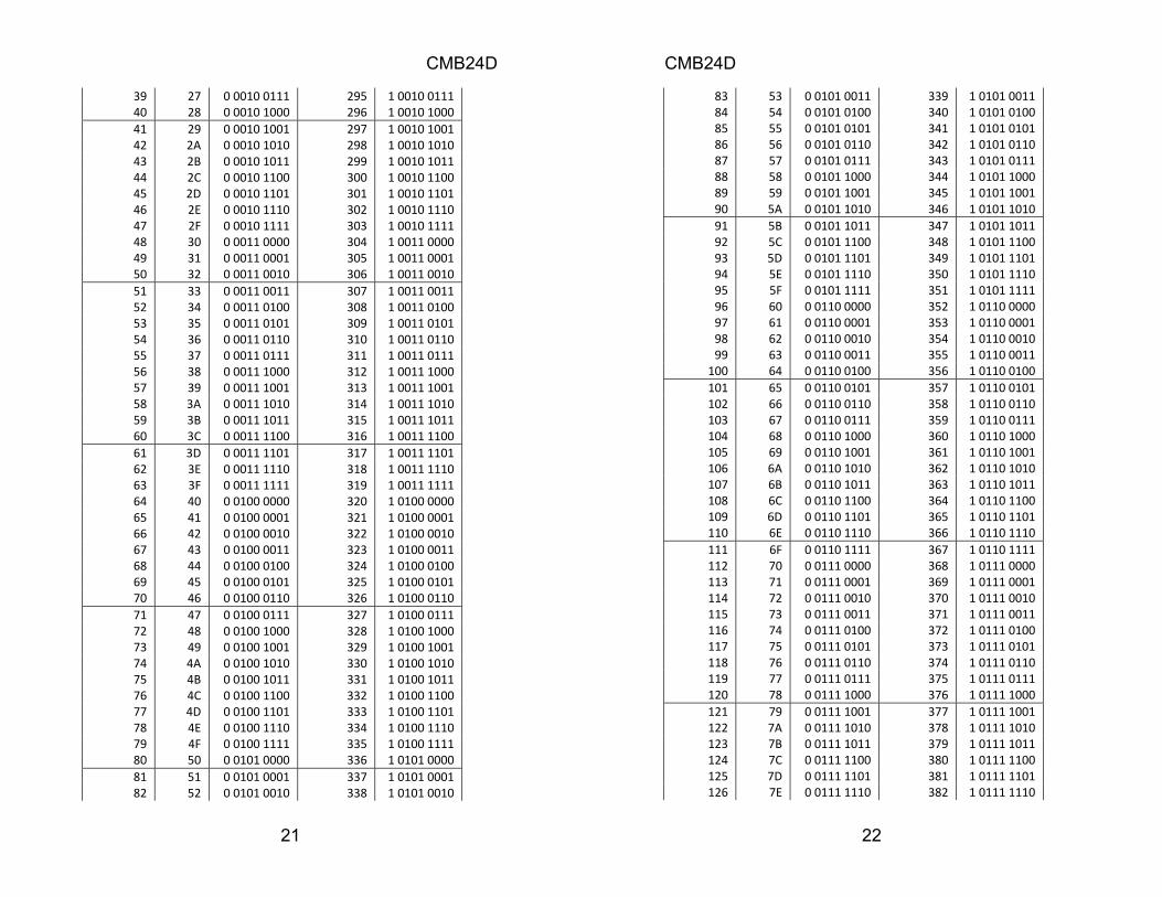
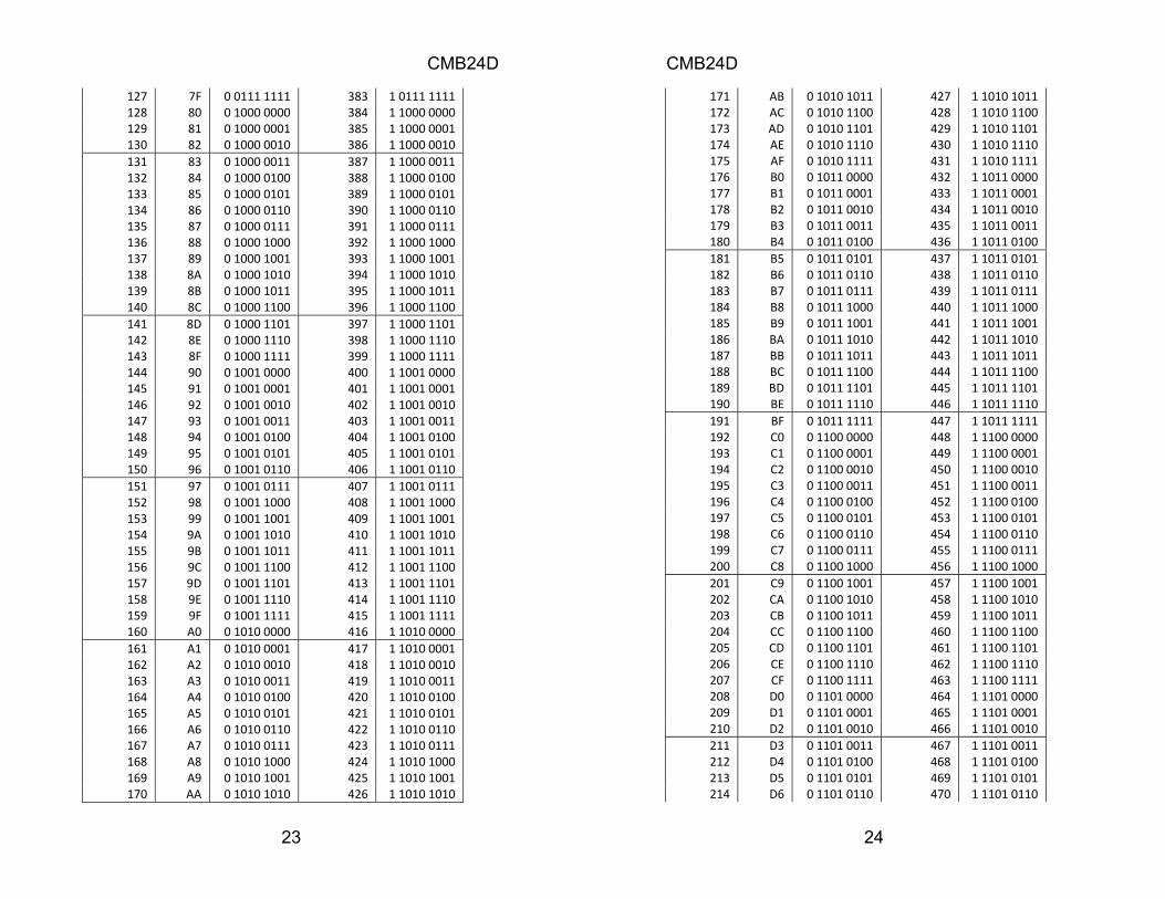
DIP Switch Address Settings ‘1’ means On and ‘0’ means Off. DMX Start LOR ID Switch 1‐9 DMX Start Switch 1‐9
1 01 0 0000 0001 257 1 0000 0001 2 02 0 0000 0010 258 1 0000 0010 3 03 0 0000 0011 259 1 0000 0011 4 04 0 0000 0100 260 1 0000 0100 5 05 0 0000 0101 261 1 0000 0101 6 06 0 0000 0110 262 1 0000 0110 7 07 0 0000 0111 263 1 0000 0111 8 08 0 0000 1000 264 1 0000 1000 9 09 0 0000 1001 265 1 0000 1001 10 0A 0 0000 1010 266 1 0000 1010 11 0B 0 0000 1011 267 1 0000 1011 12 0C 0 0000 1100 268 1 0000 1100 13 0D 0 0000 1101 269 1 0000 1101 14 0E 0 0000 1110 270 1 0000 1110 15 0F 0 0000 1111 271 1 0000 1111 16 10 0 0001 0000 272 1 0001 0000 17 11 0 0001 0001 273 1 0001 0001 18 12 0 0001 0010 274 1 0001 0010 19 13 0 0001 0011 275 1 0001 0011 20 14 0 0001 0100 276 1 0001 0100 21 15 0 0001 0101 277 1 0001 0101 22 16 0 0001 0110 278 1 0001 0110 23 17 0 0001 0111 279 1 0001 0111 24 18 0 0001 1000 280 1 0001 1000 25 19 0 0001 1001 281 1 0001 1001 26 1A 0 0001 1010 282 1 0001 1010 27 1B 0 0001 1011 283 1 0001 1011 28 1C 0 0001 1100 284 1 0001 1100 29 1D 0 0001 1101 285 1 0001 1101 30 1E 0 0001 1110 286 1 0001 1110 31 1F 0 0001 1111 287 1 0001 1111 32 20 0 0010 0000 288 1 0010 0000 33 21 0 0010 0001 289 1 0010 0001 34 22 0 0010 0010 290 1 0010 0010 35 23 0 0010 0011 291 1 0010 0011 36 24 0 0010 0100 292 1 0010 0100 37 25 0 0010 0101 293 1 0010 0101 38 26 0 0010 0110 294 1 0010 0110
CMB24D
21
39 27 0 0010 0111 295 1 0010 0111 40 28 0 0010 1000 296 1 0010 1000 41 29 0 0010 1001 297 1 0010 1001 42 2A 0 0010 1010 298 1 0010 1010 43 2B 0 0010 1011 299 1 0010 1011 44 2C 0 0010 1100 300 1 0010 1100 45 2D 0 0010 1101 301 1 0010 1101 46 2E 0 0010 1110 302 1 0010 1110 47 2F 0 0010 1111 303 1 0010 1111 48 30 0 0011 0000 304 1 0011 0000 49 31 0 0011 0001 305 1 0011 0001 50 32 0 0011 0010 306 1 0011 0010 51 33 0 0011 0011 307 1 0011 0011 52 34 0 0011 0100 308 1 0011 0100 53 35 0 0011 0101 309 1 0011 0101 54 36 0 0011 0110 310 1 0011 0110 55 37 0 0011 0111 311 1 0011 0111 56 38 0 0011 1000 312 1 0011 1000 57 39 0 0011 1001 313 1 0011 1001 58 3A 0 0011 1010 314 1 0011 1010 59 3B 0 0011 1011 315 1 0011 1011 60 3C 0 0011 1100 316 1 0011 1100 61 3D 0 0011 1101 317 1 0011 1101 62 3E 0 0011 1110 318 1 0011 1110 63 3F 0 0011 1111 319 1 0011 1111 64 40 0 0100 0000 320 1 0100 0000 65 41 0 0100 0001 321 1 0100 0001 66 42 0 0100 0010 322 1 0100 0010 67 43 0 0100 0011 323 1 0100 0011 68 44 0 0100 0100 324 1 0100 0100 69 45 0 0100 0101 325 1 0100 0101 70 46 0 0100 0110 326 1 0100 0110 71 47 0 0100 0111 327 1 0100 0111 72 48 0 0100 1000 328 1 0100 1000 73 49 0 0100 1001 329 1 0100 1001 74 4A 0 0100 1010 330 1 0100 1010 75 4B 0 0100 1011 331 1 0100 1011 76 4C 0 0100 1100 332 1 0100 1100 77 4D 0 0100 1101 333 1 0100 1101 78 4E 0 0100 1110 334 1 0100 1110 79 4F 0 0100 1111 335 1 0100 1111 80 50 0 0101 0000 336 1 0101 0000 81 51 0 0101 0001 337 1 0101 0001 82 52 0 0101 0010 338 1 0101 0010
CMB24D
22
83 53 0 0101 0011 339 1 0101 0011 84 54 0 0101 0100 340 1 0101 0100 85 55 0 0101 0101 341 1 0101 0101 86 56 0 0101 0110 342 1 0101 0110 87 57 0 0101 0111 343 1 0101 0111 88 58 0 0101 1000 344 1 0101 1000 89 59 0 0101 1001 345 1 0101 1001 90 5A 0 0101 1010 346 1 0101 1010 91 5B 0 0101 1011 347 1 0101 1011 92 5C 0 0101 1100 348 1 0101 1100 93 5D 0 0101 1101 349 1 0101 1101 94 5E 0 0101 1110 350 1 0101 1110 95 5F 0 0101 1111 351 1 0101 1111 96 60 0 0110 0000 352 1 0110 0000 97 61 0 0110 0001 353 1 0110 0001 98 62 0 0110 0010 354 1 0110 0010 99 63 0 0110 0011 355 1 0110 0011 100 64 0 0110 0100 356 1 0110 0100 101 65 0 0110 0101 357 1 0110 0101 102 66 0 0110 0110 358 1 0110 0110 103 67 0 0110 0111 359 1 0110 0111 104 68 0 0110 1000 360 1 0110 1000 105 69 0 0110 1001 361 1 0110 1001 106 6A 0 0110 1010 362 1 0110 1010 107 6B 0 0110 1011 363 1 0110 1011 108 6C 0 0110 1100 364 1 0110 1100 109 6D 0 0110 1101 365 1 0110 1101 110 6E 0 0110 1110 366 1 0110 1110 111 6F 0 0110 1111 367 1 0110 1111 112 70 0 0111 0000 368 1 0111 0000 113 71 0 0111 0001 369 1 0111 0001 114 72 0 0111 0010 370 1 0111 0010 115 73 0 0111 0011 371 1 0111 0011 116 74 0 0111 0100 372 1 0111 0100 117 75 0 0111 0101 373 1 0111 0101 118 76 0 0111 0110 374 1 0111 0110 119 77 0 0111 0111 375 1 0111 0111 120 78 0 0111 1000 376 1 0111 1000 121 79 0 0111 1001 377 1 0111 1001 122 7A 0 0111 1010 378 1 0111 1010 123 7B 0 0111 1011 379 1 0111 1011 124 7C 0 0111 1100 380 1 0111 1100 125 7D 0 0111 1101 381 1 0111 1101 126 7E 0 0111 1110 382 1 0111 1110
CMB24D
23
127 7F 0 0111 1111 383 1 0111 1111 128 80 0 1000 0000 384 1 1000 0000 129 81 0 1000 0001 385 1 1000 0001 130 82 0 1000 0010 386 1 1000 0010 131 83 0 1000 0011 387 1 1000 0011 132 84 0 1000 0100 388 1 1000 0100 133 85 0 1000 0101 389 1 1000 0101 134 86 0 1000 0110 390 1 1000 0110 135 87 0 1000 0111 391 1 1000 0111 136 88 0 1000 1000 392 1 1000 1000 137 89 0 1000 1001 393 1 1000 1001 138 8A 0 1000 1010 394 1 1000 1010 139 8B 0 1000 1011 395 1 1000 1011 140 8C 0 1000 1100 396 1 1000 1100 141 8D 0 1000 1101 397 1 1000 1101 142 8E 0 1000 1110 398 1 1000 1110 143 8F 0 1000 1111 399 1 1000 1111 144 90 0 1001 0000 400 1 1001 0000 145 91 0 1001 0001 401 1 1001 0001 146 92 0 1001 0010 402 1 1001 0010 147 93 0 1001 0011 403 1 1001 0011 148 94 0 1001 0100 404 1 1001 0100 149 95 0 1001 0101 405 1 1001 0101 150 96 0 1001 0110 406 1 1001 0110 151 97 0 1001 0111 407 1 1001 0111 152 98 0 1001 1000 408 1 1001 1000 153 99 0 1001 1001 409 1 1001 1001 154 9A 0 1001 1010 410 1 1001 1010 155 9B 0 1001 1011 411 1 1001 1011 156 9C 0 1001 1100 412 1 1001 1100 157 9D 0 1001 1101 413 1 1001 1101 158 9E 0 1001 1110 414 1 1001 1110 159 9F 0 1001 1111 415 1 1001 1111 160 A0 0 1010 0000 416 1 1010 0000 161 A1 0 1010 0001 417 1 1010 0001 162 A2 0 1010 0010 418 1 1010 0010 163 A3 0 1010 0011 419 1 1010 0011 164 A4 0 1010 0100 420 1 1010 0100 165 A5 0 1010 0101 421 1 1010 0101 166 A6 0 1010 0110 422 1 1010 0110 167 A7 0 1010 0111 423 1 1010 0111 168 A8 0 1010 1000 424 1 1010 1000 169 A9 0 1010 1001 425 1 1010 1001 170 AA 0 1010 1010 426 1 1010 1010
CMB24D
24
171 AB 0 1010 1011 427 1 1010 1011 172 AC 0 1010 1100 428 1 1010 1100 173 AD 0 1010 1101 429 1 1010 1101 174 AE 0 1010 1110 430 1 1010 1110 175 AF 0 1010 1111 431 1 1010 1111 176 B0 0 1011 0000 432 1 1011 0000 177 B1 0 1011 0001 433 1 1011 0001 178 B2 0 1011 0010 434 1 1011 0010 179 B3 0 1011 0011 435 1 1011 0011 180 B4 0 1011 0100 436 1 1011 0100 181 B5 0 1011 0101 437 1 1011 0101 182 B6 0 1011 0110 438 1 1011 0110 183 B7 0 1011 0111 439 1 1011 0111 184 B8 0 1011 1000 440 1 1011 1000 185 B9 0 1011 1001 441 1 1011 1001 186 BA 0 1011 1010 442 1 1011 1010 187 BB 0 1011 1011 443 1 1011 1011 188 BC 0 1011 1100 444 1 1011 1100 189 BD 0 1011 1101 445 1 1011 1101 190 BE 0 1011 1110 446 1 1011 1110 191 BF 0 1011 1111 447 1 1011 1111 192 C0 0 1100 0000 448 1 1100 0000 193 C1 0 1100 0001 449 1 1100 0001 194 C2 0 1100 0010 450 1 1100 0010 195 C3 0 1100 0011 451 1 1100 0011 196 C4 0 1100 0100 452 1 1100 0100 197 C5 0 1100 0101 453 1 1100 0101 198 C6 0 1100 0110 454 1 1100 0110 199 C7 0 1100 0111 455 1 1100 0111 200 C8 0 1100 1000 456 1 1100 1000 201 C9 0 1100 1001 457 1 1100 1001 202 CA 0 1100 1010 458 1 1100 1010 203 CB 0 1100 1011 459 1 1100 1011 204 CC 0 1100 1100 460 1 1100 1100 205 CD 0 1100 1101 461 1 1100 1101 206 CE 0 1100 1110 462 1 1100 1110 207 CF 0 1100 1111 463 1 1100 1111 208 D0 0 1101 0000 464 1 1101 0000 209 D1 0 1101 0001 465 1 1101 0001 210 D2 0 1101 0010 466 1 1101 0010 211 D3 0 1101 0011 467 1 1101 0011 212 D4 0 1101 0100 468 1 1101 0100 213 D5 0 1101 0101 469 1 1101 0101 214 D6 0 1101 0110 470 1 1101 0110

CMB24D
25
215 D7 0 1101 0111 471 1 1101 0111 216 D8 0 1101 1000 472 1 1101 1000 217 D9 0 1101 1001 473 1 1101 1001 218 DA 0 1101 1010 474 1 1101 1010 219 DB 0 1101 1011 475 1 1101 1011 220 DC 0 1101 1100 476 1 1101 1100 221 DD 0 1101 1101 477 1 1101 1101 222 DE 0 1101 1110 478 1 1101 1110 223 DF 0 1101 1111 479 1 1101 1111 224 E0 0 1110 0000 480 1 1110 0000 225 E1 0 1110 0001 481 1 1110 0001 226 E2 0 1110 0010 482 1 1110 0010 227 E3 0 1110 0011 483 1 1110 0011 228 E4 0 1110 0100 484 1 1110 0100 229 E5 0 1110 0101 485 1 1110 0101 230 E6 0 1110 0110 486 1 1110 0110 231 E7 0 1110 0111 487 1 1110 0111 232 E8 0 1110 1000 488 1 1110 1000 233 E9 0 1110 1001 489 1 1110 1001 234 EA 0 1110 1010 490 1 1110 1010 235 EB 0 1110 1011 491 1 1110 1011 236 EC 0 1110 1100 492 1 1110 1100 237 ED 0 1110 1101 493 1 1110 1101 238 EE 0 1110 1110 494 1 1110 1110 239 EF 0 1110 1111 495 1 1110 1111 240 F0 0 1111 0000 496 1 1111 0000 241 0 1111 0001 497 1 1111 0001 242 0 1111 0010 498 1 1111 0010 243 0 1111 0011 499 1 1111 0011 244 0 1111 0100 500 1 1111 0100 245 0 1111 0101 501 1 1111 0101 246 0 1111 0110 502 1 1111 0110 247 0 1111 0111 503 1 1111 0111 248 0 1111 1000 504 1 1111 1000 249 0 1111 1001 505 1 1111 1001 250 0 1111 1010 506 1 1111 1010 251 0 1111 1011 507 1 1111 1011 252 0 1111 1100 508 1 1111 1100 253 0 1111 1101 509 1 1111 1101 254 0 1111 1110 510 1 1111 1110 255 0 1111 1111 511 1 1111 1111 256 1 0000 0000 512 n/a
CMB24D
26
CMB24D
27
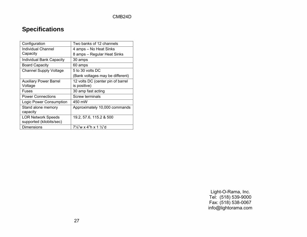
Specifications Configuration Two banks of 12 channels Individual Channel Capacity
4 amps – No Heat Sinks 8 amps – Regular Heat Sinks
Individual Bank Capacity 30 amps Board Capacity 60 amps Channel Supply Voltage 5 to 30 volts DC
(Bank voltages may be different) Auxiliary Power Barrel Voltage
12 volts DC (center pin of barrel is positive)
Fuses 30 amp fast acting Power Connections Screw terminals Logic Power Consumption 450 mW Stand alone memory capacity
Approximately 10,000 commands
LOR Network Speeds supported (kilobits/sec)
19.2, 57.6, 115.2 & 500
Dimensions 7¼”w x 4”h x 1 ½”d
Light-O-Rama, Inc. Tel: (518) 539-9000 Fax: (518) 538-0067 [email protected]


![DMX-Master MK II ENC DMX-Master I, DMX-controller · DMX-Master I, DMX-Master MK II ENC 21. 5 [FOG MACHINE] Aktiviert die Nebelmaschine. Die Kontroll-LEDs zeigen den aktuellen Betriebszustand](https://img.dokumen.tips/doc/110x75/5b87f1487f8b9a46538cafd4/dmx-master-mk-ii-enc-dmx-master-i-dmx-controller-dmx-master-i-dmx-master-mk.jpg)