Embed Size (px)
Citation preview

Short Stroke Block Cylinder withMechanical Switches, Heavy Duty Seriese
n
Cilindri oleodinamici a corsa breve con interruttori meccanici di fine corsa, serie pesante
it
v4
50
CM
Hydraulischer Kurzhubzylinder mit mechanischenendschaltern, schwere Ausführung
De
vérins Hydrauliques Course Courte avec détecteurs mécaniques de fin de course, Série Lourde
frv
45
0c
m 450bar
cat. 2020.01.v450cm.01

m2
v4
50
cm
cm 050 b
ØX
016
025
032
040
050
063
080
100
M6 M8 > M21
g
M8 > M21
g
Standard BSP (gas) thread
BSP (gas) gewinde
Filetto BSP (gas) standard
Filetage BSP (gas)
n
nPt thread
nPt gewinde
Filetto nPt
Filetage nPt
O
manifold with O-Rings
Ölanschluß durch O-Ringe
Integrati con O-ring
Intégrés avec joint torique
h
M8 > M21
cyl
ind
er m
od
el
Zylin
der
mo
del
l
mo
del
lo c
ilind
ro
mo
dèl
e d
u vé
rin
Bo
reB
ohr
ung
ale
sag
gio
alé
sag
e
cla
mp
ing
Sty
le
Bef
esti
gun
gs
art
Fiss
agg
io
Fixa
tio
n
Oil
Po
rts
typ
e
art
der
ans
chlü
sse
Tip
o d
i ori
fizi
Typ
e d
’ori
fice
Oil
Po
rts
Po
siti
on
Lage
der
Lei
tung
sans
chlü
sse
Po
sizi
one
ori
fizi
Po
siti
on
des
ori
fice
s
H
Left Side (threaded)
gewinde Links
Sinistra (filettato)
Gauche (fileté)
m
Right Side (threaded)
gewinde Rechts
Destra (filettato)
Droite (fileté)
d
Left+Right Side (threaded)
Rechts und Links Ölanschlüsse (mit gewinde)
Sinistro+destro (filettato)
Gauche + Droite (fileté)
E
Bottom Side (O-Rings)
Seitliche Ölanschlüsse (durch O-Ringe)
Lato inferiore (O-ring)
dessous (O-rings)
F
Front Side (O-Rngs)
Frontale Ölanschlüsse (durch O-Ringe)
Lato frontale (O-ring)
avant (O-rings)
R
Rear Side (O-Rings)
Hintere Ölanschlüsse (durch O-Ringe)
Lato posteriore (O-ring)
arrière (O-rings)
OrDer CODeen
CODiCe OrDineit
BeSteLLCODeDe
CODe COMMAnDefr
B
c
E
g
Page Seite Pagina Page
ØY
ØX

m3
v4
50
cm
g
M22
g
Female metric thread
metrisches Innengewinde
Filetto femmina metrico
taraudage métrique
a
male metric thread
metrisches aussengewinde
Filetto maschio metrico
Filetage métrique
I
Female UnF thread
UnF Innengewinde
Filetto femmina UnF
taraudage UnF
H
UnF-UnEF male thread
UnF-UnEF aussengewinde
Filetto maschio UnF-UnEF
Filetage male UnF-UnEF
L
Female metric thread,Bigger Rod
metrisches Innengewinde, großere Kolbenstange
Filetto femmina metrico,stelo maggiorato
taraudage métrique, tige augmentée
m
Female UnF thread,Bigger Rod
UnF Innengewinde, großere Kolbenstange
Filetto femmina UnF,stelo maggiorato
taraudage UnF,tige augmentée
#
M23 > M25
050
M7
Z
mTa20X250
M28
rm0502710a
M29
Rm + ØX + 2710a
040
050
063
080
100
Ro
d e
nd t
ype
Ko
lben
stan
gen
aus
führ
ung
Estr
emit
à st
elo
Ext
rém
ité
de
la t
ige
cyl
ind
er v
ersi
on
Zylin
der
-ver
sio
n
ver
sio
ne c
ilind
ro
ver
sio
n d
u vé
rin
Stro
keH
ublä
nge
co
rsa
co
urse
Ro
d a
cces
sori
es
Zub
eho
r K
olb
enst
ang
e
acc
esso
ri s
telo
acc
esso
ires
de
la t
ige
Flan
ge
Flan
sch
Flan
gia
Bri
de
+ \
#
Q
t
w
P
v
Z
X
y
#
none
Ohne
nessuno
aucun
mta
male thread
aussengewinde
Filetto maschio
Filetage
mFa
Floating Joint
Hammerkopf
testa a martello
tenon
dFa
Floating Joint with Female
Hammerkopf mitgegenstück
testa a martello con femmina
tenon male/femelle
Z

m4
v4
50
cm
maximum Static Pressure
maximaler statischer druck
Pressione massima statica
Pression statique maximalemaximum nominal delivery (Pushing)
Nennwert Max. Durchflussmenge(beim ausfahren)
Portata massima nominale
débit nominal maximum (en poussée)manifold Oil delivery*
Ölanschluß durch O-Ringe*
Alimentaz. con O-ring*
alimentation avec O-ring*
threaded Oil delivery
gewindebohrungen
Orifizi filettati
Orifices filetés
ØX MPa - (bar) - PSi MPa - (bar) - PSi l/min
16 22,5 - (225) - 3265 45 - (450) - 6525 1
25 22,5 - (225) - 3265 45 - (450) - 6525 3
32 22,5 - (225) - 3265 45 - (450) - 6525 5
40 22,5 - (225) - 3265 45 - (450) - 6525 7
50 22,5 - (225) - 3265 45 - (450) - 6525 12
63 17,5 - (175) - 2540 35 - (350) - 5075 18
80 15 - (150) - 2175 30 - (300) - 4350 30
100 15 - (150) - 2175 30 - (300) - 4350 45
* : Oil delivery with manifold at higher pressures can bring oil leakages from delivery O-rings.
* : Übersteigt der Betriebsdruck die angegebenen Werte, führt dies bei Zylindern mit Anschluss über O-Ringe zum Ölaustritt an den O-Ringen.
* : L’uso dei cilindri con alimentazione integrata a pressioni superiori può provocare perdite di olio dagli O-ring di alimentazione.
* : L’utilisation du vérin avec alimentation intégrée à une pression supérieure peut provoquer une fuite d’huile au niveau des O-rings d’alimentation.
teCHniCAL AnD WOrKinG CHArACteriStiCS CHArten
tABeLLe teCHniSCHe MerKMALe UnD fUnKtiOnDe
tABLeAU DeS CArACtériStiqUeS teCHniqUeS et De fOnCtiOnneMent fr
tABeLLA CArAtteriStiCHe teCniCHe e Di fUnZiOnAMentOit
ØX = Bore Bohrung alesaggio alésage

m5
v4
50
cm
max mass applicable at max Speed
max. bewegbare massebei max. geschwindigkeit.
massa max applicabilealla velocità max
masse maximum applicableà la vitesse maxi
maximum Piston Speed
maximale geschwindigkeitdes Kolbens
velocità massima pistone
vitesse maximum du vérin
maximum working temperature
max. Betriebstemperatur
Temperatura massima esercizio
température max. d’exercice
with Switches
mit mikroendschalter
con micro
avec détecteurs
without Switches
Ohne mikroendschalter
Senza micro
Sans détecteur
ØX Kg m/s
16 2
0,1
80°c - 176° F
160 °c - 320 °F
25 4
32 10
40 17
80°c
176° F
“T” - “V”
160°c
320° F
50 25
63 30
80 40
100 45
ØX = Bore Bohrung alesaggio alésage

m6
v4
50
cm
table for push and pull forces in dan (1 dan = 1 kgf)
tabelle druck- und Zugkraft in dan (1 dan=1 kgf)
Tabella forze in spinta e tiro in daN (1 daN = 1 kgf)
tableau des forces de poussée et de traction en dan (1 dan=1 kgf)
BOre SiZe AnD StrOKeen
ALéSAGeS et COUrSeSfrALeSAGGiO e COrSAit
KOLBenDUrCHMeSSer UnD HUBLÄnGeDe
ØX
cm 050 b g h
8 MPa80 bar
1160 PSi
14 MPa140 bar
2030 PSi
20 MPa200 bar
2900 PSi
25 MPa250 bar
3626 PSi
30 MPa300 bar
4350 PSi
40 MPa400 bar
5800 PSi
ØX
ØY*
th tr th tr th tr th tr th tr th tra HL M
g i
016 10 10 161 98 281 171 402 245 502 306 603 367 804 489
025 18 18 393 189 687 331 981 473 1227 591 1472 709 1963 945
032 22 22 643 339 1125 593 1608 848 2010 1060 2412 1272 3215 1696
040 22 22 1005 701 1758 1226 2512 1752 3140 2190 3768 2628 5024 3504
05028 1570 1078 2748 1886 3925 2694 4906 3368 5888 4041 7850 5388
36 1570 756 2748 1323 3925 1890 4906 2363 5888 2835 7850 3781
06328 2493 2000 4362 3500 6231 5000 7789 6251 9347 7501 - -
36 2493 1679 4362 2938 6231 4197 7789 5246 9347 6295 - -
08036 4019 3205 7034 5609 10048 8013 12560 10017 15072 12020 - -
45 4019 2748 7034 4808 10048 6869 12560 8586 15072 10303 - -
10045 6280 5008 10990 8765 15700 12521 19625 15651 23550 18781 - -
56 6280 4311 10990 7544 15700 10776 19625 13471 23550 16165 - -
* : depending on rod end (see page m22) abhänging von dem Kolbenstangenende (siehe Seite m22)
*: dipende dall’estremità stelo (vedi pagina m22) dépend de l’extrémité de la tige (voir page m22)
thrust druck Spinta Poussée
traction Zug Trazione traction
th
tr
ØX Bore Bohrung alesaggio alésage
Øy Rod Kolbenstange Stelo tige

m7
v4
50
cm
Z 010 020 025 030 040 050 060 080 100 120 150 160 200
ØX
16
25
32
40
50
63
80
100
Standard strokes table in mm
Standard hublängen tabelle in mm
tabella corse standard in mm
tableau des course standards en mm
NOTES: Stroke tolerance: -0/+0.5 mm. For intermediate strokes, choose the closest longer stroke, and require a stroke reducer (minimum reduction: 8 mm).Option not available for øX 16. Special strokes can be requested to our Sales department.
bEmErkuNg: Hub Toleranz -0/+0,5 mm. Für Zwischenhübe nehmen Sie den nächst grösseren Hub und einen Hubbegrenzer(außer Bohring Ø16mm).Für kundenspezifische Hublängen bitte unser Verkaufsburo kontaktieren.
NOTE: Tolleranza sulla corsa: -0/+0,5 mm. Per corse intermedie considerare la corsa immediatamente superiore e richiedere il riduttore di corsa (riduzione minima: 8 mm). Opzione non disponibile per øX 16. Si possono richiedere corse speciali contattando il nostro ufficio vendite.
NOTE: tolérance sur la course: -0/+0,5 mm. Per les courses intermédiaires (pas disponibles pour l’alésage Ø16) considérer la course immédiatement supérieureet demander le réducteur de la course (au minimum 8 mm). course spéciales disponibles sur demande. contacter notre bureau commercial.
Z
g # 050 mTa20X250 rm0502710a+ \
Standard strokes Standard hublängen corse standard courses standard
Special strokes Sonderhublängen corse speciali courses speciales
ØX Bore Bohrung alesaggio alésage Øy Rod Kolbenstange Stelo tige Stroke Hub corsa courseZ

m8
v4
50
cm
CHOiCe Of CLAMpinG StYLe AnD OiL DeLiverYen AUSWAHL BefeStiGUnGSArt UnD AnSCHLUSSDe
CHOiX DeS fiXAtiOnS et DeS tYpeS D’ALiMentAtiOnSfrSCeLtA DeL fiSSAGGiO e OrifiZiit
ØX
cm 050 c g h
c g hLongitudinal through holes with BSP (gas) threaded oil delivery, left side
durchgangsbohrungen und gewindeanschluss BSP (gas), links
Fori passanti longitudinali con orifizi filettati BSP (gas), lato sinistro
Trous passants longitudinaux avec orifices filetés BSP (gas), côté gauche
c n hLongitudinal through holes with nPt threaded oil delivery, left side durchgangsbohrungen und gewindeanschluss nPt, links
Fori passanti longitudinali con orifizi filettati NPT, lato sinistro Trous passants longitudinaux avec orifices filetés NPT, côté gauche
Warning: caps (t2) protrude on the left or on the right side. max. eccentricity 0.5 mm - O-rings included in the supply.Achtung: Eventuelle auskragung t2 (max. 5mm) der verschlußschrauben auf der gegenüberliegenden Seite der anschlüße berücksichtigen.O-Ringe sind im Lieferumfang enthalten.Attenzione: Sporgenza tappi (T2) sul lato sinistro o sul destro. Eccentricità max 0,5 mm - O-ring compresi nella fornitura.Attention: Dépassement (T2) des bouchons sur le côté gauche ou sur le côté droit. Excentricité Max. 0,5 mm - O-rings inclus dans la livraison.
#1 :
c n mLongitudinal through holes with nPt threaded oil delivery, right side durchgangsbohrungen und gewindeanschluss nPt, rechts
Fori passanti longitudinali con orifizi filettati NPT, lato destro Trous passants longitudinaux avec orifices filetés NPT, côté droit
c g mLongitudinal through holes with BSP (gas) threaded oil delivery, right side
durchgangsbohrungen und gewindeanschluss BSP (gas), rechts
Fori passanti longitudinali con orifizi filettati BSP (gas), lato destro
Trous passants longitudinaux avec orifices filetés BSP (gas), côté droit

m9
v4
50
cm
CHOiX DeS fiXAtiOnS et DeS tYpeS D’ALiMentAtiOnS
Z
g # 050 mTa20X250 rm0502710a+ \
eg. ØX = 50 , Øy = 28, Z = 50mm : c + Z = 73 + 50 = 123 mm
c g dLongitudinal through holes with BSP (gas) threaded double oil delivery, left + right side
durchgangsbohrungen und beidseitiger gewindeanschluss BSP (gas), rechts + links
Fori passanti longitudinali con doppi orifizi filettati BSP (gas), lato sinistro + destro
Trous passants longitudinaux avec doubles orifices filetés BSP (gas), côté droit + côté gauche
c n d
Longitudinal through holes with nPt threaded double oil delivery, left + right side
durchgangsbohrungen und beidseitiger gewindeanschluss nPt, rechts + links
Fori passanti longitudinali con doppi orifizi filettati NPT, lato sinistro + destro
Trous passants longitudinaux avec doubles orifices filetés NPT, côté droit + côté gauche
ØX
ØY*
a B C+ ØD1 F g H ØQ ØQ1 L M
P
ØSBh9
Øt1 t2 V WHa HL M BSP nPt
g i
16 10 10 55 35 46 2,5 22 40 7 6,5 10,5 10,5 20,5 1/4” 1/4” 30 19 5 3 9
25 18 18 65 45 50 4 30 50 9 8,5 13,5 10,5 22 1/4” 1/4” 38 19 5 3 11
32 22 22 75 55 55 4 35 55 11 10,5 16,5 12,5 26,5 1/4” 1/4” 45 19 5 3 12
40 22 22 85 63 63 4 40 63 11 10,5 16,5 15,5 28,5 1/4” 1/4” 45 19 5 3 12
5028
100 75 73 5 45 76 13 13 19 18 29 1/4” 1/4”42
19 5 3 1236 45
63 28 36 115 90 78 6 55 90 13 13 19 21,5 29 3/8” 3/8” 50 22 5 3 13,5
80 36 45 140 110 93 6 75 110 17 17 25 26 36 1/2” 1/2” 60 27 5 3 14
100 45 56 170 140 105 8,5 95 135 17 17 25 31 42 1/2” 1/2” 72 27 5 3 15
Longitudinal through holes with nPt threaded oil delivery, left side durchgangsbohrungen und gewindeanschluss nPt, links
Fori passanti longitudinali con orifizi filettati NPT, lato sinistro Trous passants longitudinaux avec orifices filetés NPT, côté gauche
Longitudinal through holes with nPt threaded oil delivery, right side durchgangsbohrungen und gewindeanschluss nPt, rechts
Fori passanti longitudinali con orifizi filettati NPT, lato destro Trous passants longitudinaux avec orifices filetés NPT, côté droit
ØX Bore Bohrung alesaggio alésage Øy Rod Kolbenstange Stelo tige Stroke Hub corsa courseZ
NOTES: For dimensions where no tolerance is indicated, refer to dIn norm 7168-m.
ACHTuNg: Für Maße ohne Toleranzangaben gilt DIN 7168-m.
NOTE: Per le dimensioni senza indicazione di tolleranza, riferirsi alla norma DIN 7168-m.
NOTE: Pour les dimensions où la tolerance n’est pas indiquée, addressez-vous aux normes DIN 7168-m.
* : depending on rod end (see page m22) abhänging von dem Kolbenstangenende (siehe Seite m22)
*: dipende dall’estremità stelo (vedi pagina m22) dépend de l’extrémité de la tige (voir page m22)

m10
v4
50
cm
ØX
cm 050 b n h
CHOiCe Of CLAMpinG StYLe AnD OiL DeLiverYen AUSWAHL BefeStiGUnGSArt UnD AnSCHLUSSDe
CHOiX DeS fiXAtiOnS et DeS tYpeS D’ALiMentAtiOnSfrSCeLtA DeL fiSSAGGiO e OrifiZiit
b g hthreaded body clamping with BSP (gas) threaded oil delivery, left side
Gewindebohrungen zur Befestigung und Gewindeanschluss BSP (Gas), links
Fissaggio corpo filettato con orifizi filettati BSP (gas), lato sinistro
Fixation par trous taraudés avec orifices filetés BSP (gas), côté gauche
b n hthreaded body clamping with nPt threaded oil delivery, left side Gewindebohrungen zur Befestigung und Gewindeanschluss NPT, links
Fissaggio corpo filettato con orifizi filettati NPT, lato sinistro Fixation par trous taraudés avec orifices filetés NPT, côté gauche
Warning: caps (t2) protrude on the left or on the right side. max. eccentricity 0.5 mm - O-rings included in the supply.Achtung: Eventuelle auskragung t2 (max. 5mm) der verschlußschrauben auf der gegenüberliegenden Seite der anschlüße berücksichtigen.O-Ringe sind im Lieferumfang enthalten.Attenzione: Sporgenza tappi (T2) sul lato sinistro o sul destro. Eccentricità max 0,5 mm - O-ring compresi nella fornitura.Attention: Dépassement (T2) des bouchons sur le côté gauche ou sur le côté droit. Excentricité Max.0,5 mm - O-rings inclus dans la livraison.
#1 :
b n mthreaded body clamping with nPt threaded oil delivery, right side Gewindebohrungen zur Befestigung und Gewindeanschluss NPT, rechts
Fissaggio corpo filettato con orifizi filettati NPT, lato destro Fixation par trous taraudés avec orifices filetés NPT, côté droit
b g mthreaded body clamping with BSP (gas) threaded oil delivery, right side
Gewindebohrungen zur Befestigung und Gewindeanschluss BSP (Gas), rechts
Fissaggio corpo filettato con orifizi filettati BSP (gas), lato destro
Fixation par trous taraudés avec orifices filetés BSP (gas), côté droit

m11
v4
50
cm
Z
g # 050 mTa20X250 rm0502710a+ \
CHOiX DeS fiXAtiOnS et DeS tYpeS D’ALiMentAtiOnS
eg. ØX = 50 , Øy = 28, Z = 50mm : c + Z = 73 + 50 = 123 mm
b g dthreaded body clamping with BSP (gas) threaded double oil delivery, left + right side
Gewindebohrungen zur Befestigung und beidseitiger Gewindeanschluss BSP (Gas), rechts + links
Fissaggio corpo filettato con doppi orifizi filettati BSP (gas), lato sinistro + destro
Fixation par trous taraudés avec doubles orifices filetés BSP (gas), côté droit + côté gauche
b n d
threaded body clamping with nPt threaded double oil delivery, left + right side
Gewindebohrungen zur Befestigung und beidseitiger Gewindeanschluss NPT, rechts + links
Fissaggio corpo filettato con doppi orifizi filettati NPT, lato sinistro + destro
Fixation par trous taraudés avec doubles orifices filetés NPT, côté droit + côté gauche
ØX
ØY*
a B C+ ØD1 F g i J L M
P
ØSBh9
Øt1 t2 V WHa HL M BSP nPt
g i
16 10 10 55 35 46 2,5 22 40 10 m6×1 10,5 20,5 1/4” 1/4” 30 19 5 3 9
25 18 18 65 45 50 4 30 50 15 m8×1,25 10,5 22 1/4” 1/4” 38 19 5 3 11
32 22 22 75 55 55 4 35 55 20 m10×1,5 12,5 26,5 1/4” 1/4” 45 19 5 3 12
40 22 22 85 63 63 4 40 63 20 m10×1,5 15,5 28,5 1/4” 1/4” 45 19 5 3 12
5028
100 75 73 5 45 76 20 m12×1,75 18 29 1/4” 1/4”42
19 5 3 1236 45
63 28 36 115 90 78 6 55 90 20 m12×1,75 21,5 29 3/8” 3/8” 50 22 5 3 13,5
80 36 45 140 110 93 6 75 110 30 m16×2 26 36 1/2” 1/2” 60 27 5 3 14
100 45 56 170 140 105 8,5 95 135 30 m16×2 31 42 1/2” 1/2” 72 27 5 3 15
ØX Bore Bohrung alesaggio alésage Øy Rod Kolbenstange Stelo tige Stroke Hub corsa courseZ
NOTES: For dimensions where no tolerance is indicated, refer to dIn norm 7168-m.
ACHTuNg: Für Maße ohne Toleranzangaben gilt DIN 7168-m.
NOTE: Per le dimensioni senza indicazione di tolleranza, riferirsi alla norma DIN 7168-m.
NOTE: Pour les dimensions où la tolerance n’est pas indiquée, addressez-vous aux normes DIN 7168-m.
* : depending on rod end (see page m22) abhänging von dem Kolbenstangenende (siehe Seite m22)
*: dipende dall’estremità stelo (vedi pagina m22) dépend de l’extrémité de la tige (voir page m22)
m12
v4
50
cm
CHOiCe Of CLAMpinG StYLe AnD OiL DeLiverYen AUSWAHL BefeStiGUnGSArt UnD AnSCHLUSSDe
CHOiX DeS fiXAtiOnS et DeS tYpeS D’ALiMentAtiOnSfrSCeLtA DeL fiSSAGGiO e OrifiZiit
e g hKey-way clamping with BSP (gas) threaded oil delivery, left side nutbefestigung und gewindeanschluss BSP (gas), links
Fissaggio a piedino con orifizi filettati BSP (gas), lato sinistro Fixation par trous verticaux avec orifices filetés BSP (gas), côté gauche
e n hKey-way clamping with nPt threaded oil delivery, left side
nutbefestigung und gewindeanschluss nPt, links
Fissaggio a piedino con orifizi filettati NPT, lato sinistro
Fixation par trous verticaux avec orifices filetés NPT, côté gauche
NOTE 1: If utilizing this type of clamping with an oil pressure higher than 160 bar - 2320 PSI, it is better to apply a holding bracket as to avoid any torsion of the cylinder itself.bEmErkuNg 1: Bei Betrieb des Zylinders über 160 bar, sollte bei dieser Befestigungsart zusätzlich eine Nutfeder eingesetzt werden, um Torsion des Zylinders zu vermeiden.NOTA 1: In caso di utilizzo del cilindro con questo fissaggio a pressione sup. a 160 bar è consigliabile applicare un piedino posteriore per evitare torsioni del cilindro stesso.NOTE 1: En cas d’utilisation du vérin avec cette fixation à une pression sup. à 160 bars il est conseillé d’appliquer un calage arriére pour éviter la torsion du vérin sur lui-même.
e g m
e n mKey-way clamping with nPt threaded oil delivery, right side
nutbefestigung und gewindeanschluss nPt, rechts
Fissaggio a piedino con orifizi filettati NPT, lato destro
Fixation par trous verticaux avec orifices filetés NPT, côté droit
Key-way clamping with BSP (gas) threaded oil delivery, right side nutbefestigung und gewindeanschluss BSP (gas), rechts
Fissaggio a piedino con orifizi filettati BSP (gas), lato destro Fixation par trous verticaux avec orifices filetés BSP (gas), côté droit
ØX
cm 050 e g h

m13
v4
50
cm
Key-way clamping with BSP (gas) threaded oil delivery, left side nutbefestigung und gewindeanschluss BSP (gas), links
Fissaggio a piedino con orifizi filettati BSP (gas), lato sinistro Fixation par trous verticaux avec orifices filetés BSP (gas), côté gauche
Z
g # 050 mTa20X250 rm0502710a+ \
ØX
ØY*
Z C+ a B ØD1 H1 L M
P
ØQ ØQ1 RS
H 10S1
ØSB h9
U1 t V W WHa HL M BSP nPt
a HL M
g i g i
16 10 10
10
46 55 35 2,5 10 10,5 20,5 1/4” 1/4” 6,5 10,5 40 8 2 30
33,5 -
3 33,5 930 43 19
50 53 39
25 18 18
20
50 65 45 4 12 10,5 22 1/4” 1/4” 8,5 13,5 50 10 2 38
38 -
3 38 1150 56,5 37
80 71,5 67
120 91,5 107
32 22 22
20
55 75 55 4 16 12,5 26,5 1/4” 1/4” 10,5 16,5 55 12 3 45
43 -
3 43 1250 60 34
80 75 64
120 95 104
40 22 22
25
63 85 63 4 17 15,5 28,5 1/4” 1/4” 10,5 16,5 63 12 3 45
44,5 -
3 44,5 12
50 63 37
80 78 67
120 98 107
160 118 147
200 138 187
50 28 36
25
73 100 75 5 22 18 29 1/4” 1/4” 13 19 76 15 5 42 45
47 -
3 47 12
50 67 40
80 82 70
120 102 110
160 122 150
200 142 190
63 28 36
30
78 115 90 6 24 21,5 29 3/8” 3/8” 13 19 95 15 5 50
49 -
3 49 13,5
60 72,5 47
80 82,5 67
120 102,5 107
160 122,5 147
200 142,5 187
80 36 45
40
93 140 110 6 26 26 36 1/2” 1/2” 17 25 110 20 5 60
62 -
3 62 14
80 91,5 59
120 111,5 99
160 131,5 139
200 151,5 179
100 45 56
50
105 170 140 8,5 32 31 42 1/2” 1/2” 17 25 135 20 5 72
69,5 -
3 69,5 15100 108 77
150 133 127
eg. ØX = 50 , Øy = 28, Z = 50mm : c + Z = 73 + 50 = 123 mm
ØX Bore Bohrung alesaggio alésage Øy Rod Kolbenstange Stelo tige Stroke Hub corsa courseZ
e g dKey-way clamping with BSP (gas) threaded double oil delivery, left + right side
nutbefestigung und beidseitiger gewindeanschluss BSP (gas), rechts + links
Fissaggio a piedino con doppi orifizi filettati BSP (gas), lato sinistro + destro
Fixation par trous verticaux avec doubles orifices filetés BSP (gas), côté droit + côté gauche
e n d
Key-way clamping with nPt threaded double oil delivery, left + right side
nutbefestigung und beidseitiger gewindeanschluss nPt, rechts + links
Fissaggio a piedino con doppi orifizi filettati NPT, lato sinistro + destro
Fixation par trous verticaux avec doubles orifices filetés NPT, côté droit + côté gauche
NOTES: For dimensions where no tolerance is indicated, refer to dIn norm 7168-m. ACHTuNg: Für Maße ohne Toleranzangaben gilt DIN 7168-m.
NOTE: Per le dimensioni senza indicazione di tolleranza, riferirsi alla norma DIN 7168-m. NOTE: Pour les dimensions où la tolerance n’est pas indiquée, addressez-vous aux normes DIN 7168-m.
* : depending on rod end (see page m22) abhänging von dem Kolbenstangenende (siehe Seite m22)
*: dipende dall’estremità stelo (vedi pagina m22) dépend de l’extrémité de la tige (voir page m22)

m14
v4
50
cm
CHOiCe Of CLAMpinG StYLe AnD OiL DeLiverYen AUSWAHL BefeStiGUnGSArt UnD AnSCHLUSSDe
CHOiX DeS fiXAtiOnS et DeS tYpeS D’ALiMentAtiOnSfrSCeLtA DeL fiSSAGGiO e OrifiZiit
c o f
maximum eccentricity 0.5 mm. O-rings included in the supply Unmittigkeit max.: 0,5 mm. O-Ringe im Lieferumfang enthalten
Eccentricità massima 0,5 mm. O-ring compresi nella fornitura Excentricité maximum 0,5 mm. O-rings inclus dans la livraison
#2 :
c o r
ØX
cm 050 c o f
ØX
ØY*
a B C+ ØD ØD1 e F g H K ØQ ØQ1ØSBh9
V WHa HL M
g i
16 10 10 55 35 46 10 2,5 43 22 40 7 21,5 6,5 10,5 30 3 9
25 18 18 65 45 50 13 4 51 30 50 9 25,5 8,5 13,5 38 3 11
32 22 22 75 55 55 13 4 60 35 55 11 30 10,5 16,5 45 3 12
40 22 22 85 63 63 13 4 65 40 63 11 32,5 10,5 16,5 45 3 12
5028
100 75 73 13 5 80 45 76 13 40 13 1942
3 1236 45
63 28 36 115 90 78 13 6 95 55 90 13 47,5 13 19 50 3 13,5
80 36 45 140 110 93 13 6 118 75 110 17 59 17 25 60 3 14
100 45 56 170 140 105 15 8,5 140 95 135 17 70 17 25 72 3 15
Longitudinal through holes with front manifold oil delivery
durchgangsbohrungen und anschluss mit O-Ringen vorne
Fissaggio fori longitudinali passanti con orifiziintegrati frontali
trous passants longitudinaux avec orifices intégrés avant
Longitudinal through holes with rear manifold oil delivery (no for versions P, v, Z)
durchgangsbohrungen und integrierteanschlüsse über O-Ringe, hinten (nicht für version P, v, Z)
Fissaggi fori longitudinali passanticon orifizi integrati posteriori(non per versioni P, v, Z)
trous passants longitudinauxavec orifices intégrés coté arrière(pas pour versions P, v et Z)
NOTES: For dimensions where no tolerance is indicated, refer to dIn norm 7168-m. ACHTuNg: Für Maße ohne Toleranzangaben gilt DIN 7168-m.
NOTE: Per le dimensioni senza indicazione di tolleranza, riferirsi alla norma DIN 7168-m. NOTE: Pour les dimensions où la tolerance n’est pas indiquée, addressez-vous aux normes DIN 7168-m.
eg. ØX = 50 , Øy = 28, Z = 50mm : c + Z = 73 + 50 = 123 mm
ØX Bore Bohrung alesaggio alésage Øy Rod Kolbenstange Stelo tige Stroke Hub corsa courseZ
* : depending on rod end (see page m22) abhänging von dem Kolbenstangenende (siehe Seite m22)
*: dipende dall’estremità stelo (vedi pagina m22) dépend de l’extrémité de la tige (voir page m22)

m15
v4
50
cm
Z
g # 050 mTa20X250 rm0502710a+ \
b o f
b o r
threaded body clamping with front manifold oil delivery
Gewindebohrung zur Befestigung und integrierte Anschlüsse über O-Ringe, vorne
Fissaggio corpo filettato con orifiziintegrati frontali
Fixation par trous taraudés avecorifices intégrés avant
threaded body clamping with rear manifold oil delivery (no for versions P, v, Z)
Befestigungsgewinde und anschlussmit O-Ringen hinten (nicht für version P, v, Z)
Fissaggio corpo filettato conorifizi integrati posteriori(non per versioni P, v, Z)
Fixation par trous taraudés avecorifices intégrés coté arrière(pas pour versions P, v et Z)
ØX
ØY*
a B C+ ØD ØD1 e F g i J KØSBh9
V WHa HL M
g i
16 10 10 55 35 46 10 2,5 43 22 40 10 m6×1 21,5 30 3 9
25 18 18 65 45 50 10 4 51 30 50 15 m8×1,25 25,5 38 3 11
32 22 22 75 55 55 13 4 60 35 55 20 m10×1,5 30 45 3 12
40 22 22 85 63 63 13 4 65 40 63 20 m10×1,5 32,5 45 3 12
5028
100 75 73 13 5 80 45 76 20 m12×1,75 4042
3 1236 45
63 28 36 115 90 78 13 6 95 55 90 20 m12×1,75 47,5 50 3 13,5
80 36 45 140 110 93 13 6 118 75 110 30 m16×2 59 60 3 14
100 45 56 170 140 105 15 8,5 140 95 135 30 m16×2 70 72 3 15
NOTES: For dimensions where no tolerance is indicated, refer to dIn norm 7168-m. ACHTuNg: Für Maße ohne Toleranzangaben gilt DIN 7168-m.
NOTE: Per le dimensioni senza indicazione di tolleranza, riferirsi alla norma DIN 7168-m. NOTE: Pour les dimensions où la tolerance n’est pas indiquée, addressez-vous aux normes DIN 7168-m.
eg. ØX = 50 , Øy = 28, Z = 50mm : c + Z = 73 + 50 = 123 mm
ØX Bore Bohrung alesaggio alésage Øy Rod Kolbenstange Stelo tige Stroke Hub corsa courseZ
maximum eccentricity 0.5 mm. O-rings included in the supply Unmittigkeit max.: 0,5 mm. O-Ringe im Lieferumfang enthalten
Eccentricità massima 0,5 mm. O-ring compresi nella fornitura Excentricité maximum 0,5 mm. O-rings inclus dans la livraison
#2 :
* : depending on rod end (see page m22) abhänging von dem Kolbenstangenende (siehe Seite m22)
*: dipende dall’estremità stelo (vedi pagina m22) dépend de l’extrémité de la tige (voir page m22)

m16
v4
50
cm
CHOiCe Of CLAMpinG StYLe AnD OiL DeLiverYen AUSWAHL BefeStiGUnGSArt UnD AnSCHLUSSDe
CHOiX DeS fiXAtiOnS et DeS tYpeS D’ALiMentAtiOnSfrSCeLtA DeL fiSSAGGiO e OrifiZiit
c g r
ØX
cm 050 c g r
Longitudinal through holes with threaded BSP (gas) oil delivery, rear side (no for versions P, v, Z)
durchgangsbohrungen und gewindeanschluss BSP (gas), hinten (nicht für version P, v, Z)
Fori passanti longitudinali con orifizi filettati BSP (gas), lato posteriore (Non per versioni P, V, Z)
Trous passants longitudinaux avec orifices filetés BSP (gas), côté arrière (pas pour versions P, V et Z)
c n rLongitudinal through holes with threaded nPt oil delivery, rear side (no for versions P, v, Z)
durchgangsbohrungen und gewindeanschluss nPt, hinten (nicht für version P, v, Z)
Fori passanti longitudinali con orifizi filettati NPT, lato posteriore (Non per versioni P,V,Z)
Trous passants longitudinaux avec orifices filetés NPT, côté arrière (pas pour versions P, V et Z)
b g rthreaded body clamping with BSP (gas) threaded oil delivery, rear side (no for versions P, v, Z)
Befestigungsgewinde und gewindeanschluss BSP (gas), hinten (nicht für version P, v, Z)
Fissaggio corpo filettato con orifizi filettati BSP (GAS), lato posteriore (Non per versioni P, V, Z)
Fixation par trous taraudés avec orifices filetés BSP (gas), côté arrière (pas pour versions P, V et Z)
b n rthreaded body clamping with nPt threaded oil delivery, rear side (no for versions P, v, Z)
Befestigungsgewinde und gewindeanschluss nPt, hinten (nicht für version P, v, Z)
Fissaggio corpo filettato con orifizi filettati NPT, lato posteriore (Non per versioni P, V, Z)
Fixation par trous taraudés avec orifices filetés NPT, côté arrière (pas pour versions P, V et Z)

m17
v4
50
cm
Z
g # 050 mTa20X250 rm0502710a+ \
ØX
ØY*
a B C+ ØD1 F g H i J ØQ ØQ1
P
R1 R2ØSB h9
V WHa HL M BSP nPt
g i
16 10 10 55 35 46 2,5 22 40 7 10 m6×1 6,5 10,5 1/8” 1/8” 30 12,5 30 3 9
25 18 18 65 45 50 4 30 50 9 15 m8×1,25 8,5 13,5 1/8” 1/8” 39 13 38 3 11
32 22 22 75 55 55 4 35 55 11 20 m10×1,5 10,5 16,5 1/8” 1/8” 47,5 14,5 45 3 12
40 22 22 85 63 63 4 40 63 11 20 m10×1,5 10,5 16,5 1/8” 1/8” 56,5 13 45 3 12
50
28
100 75 73 5 45 76 13 20 m12×1,75 13 19 1/4” 1/4” 64 17
42
3 12
36 45
63 28 36 115 90 78 6 55 90 13 20 m12×1,75 13 19 1/4” 1/4” 66 17 50 3 13,5
80 36 45 140 110 93 6 75 110 17 30 m16×2 17 25 1/4” 1/4” 85 18 60 3 14
100 45 56 170 140 105 8,5 95 135 17 30 m16×2 17 25 3/8” 3/8” 103 20 72 3 15
eg. ØX = 50 , Øy = 28, Z = 50mm : c + Z = 73 + 50 = 123 mm
ØX Bore Bohrung alesaggio alésage Øy Rod Kolbenstange Stelo tige Stroke Hub corsa courseZ
NOTES: For dimensions where no tolerance is indicated, refer to dIn norm 7168-m.
ACHTuNg: Für Maße ohne Toleranzangaben gilt DIN 7168-m.
NOTE: Per le dimensioni senza indicazione di tolleranza, riferirsi alla norma DIN 7168-m.
NOTE: Pour les dimensions où la tolerance n’est pas indiquée, addressez-vous aux normes DIN 7168-m.
* : depending on rod end (see page m22) abhänging von dem Kolbenstangenende (siehe Seite m22)
*: dipende dall’estremità stelo (vedi pagina m22) dépend de l’extrémité de la tige (voir page m22)

m18
v4
50
cm
CHOiCe Of CLAMpinG StYLe AnD OiL DeLiverYen AUSWAHL BefeStiGUnGSArt UnD AnSCHLUSSDe
CHOiX DeS fiXAtiOnS et DeS tYpeS D’ALiMentAtiOnSfrSCeLtA DeL fiSSAGGiO e OrifiZiit
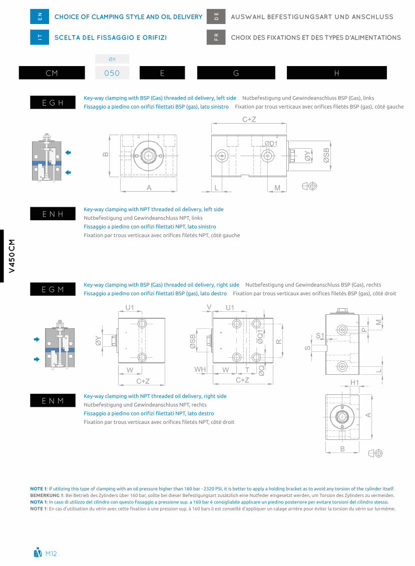
ØX
cm 050 g g h
g g hKey-way clamping with BSP (gas) threaded oil delivery, left side (long stroke)
nutbefestigung und gewindeanschluss BSP (gas), links (langhub)
Fissaggio a piedino con orifizi filettati BSP (gas), lato sinistro (corse lunghe)
Fixation par trous verticaux avec orifices filetés BSP (gas), côté gauche (courses longues)
g n hKey-way clamping with nPt threaded oil delivery, left side (long stroke)
nutbefestigung und gewindeanschluss nPt, links (langhub)
Fissaggio a piedino con orifizi filettati NPT, lato sinistro (corse lunghe)
Fixation par trous verticaux avec orifices filetés NPT, côté gauche (courses longues)
g g mKey-way clamping with BSP (gas) threaded oil delivery, right side (long stroke)
nutbefestigung und gewindeanschluss BSP (gas), rechts (langhub)
Fissaggio a piedino con orifizi filettati BSP (gas), lato destro (corse lunghe)
Fixation par trous verticaux avec orifices filetés BSP (gas), côté droit (courses longues)
g n mKey-way clamping with nPt threaded oil delivery, right side (long stroke)
nutbefestigung und gewindeanschluss nPt, rechts (langhub)
Fissaggio a piedino con orifizi filettati NPT, lato destro (corse lunghe)
Fixation par trous verticaux avec orifices filetés NPT, côté droit (courses longues)
NOTE 1: If utilizing this type of clamping with an oil pressure higher than 160 bar - 2320 PSI, it is better to apply a holding bracket as to avoid any torsion of the cylinder itself.bEmErkuNg 1: Bei Betrieb des Zylinders über 160 bar, sollte bei dieser Befestigungsart zusätzlich eine Nutfeder eingesetzt werden, um Torsion des Zylinders zu vermeiden.NOTA 1: In caso di utilizzo del cilindro con questo fissaggio a pressione sup. a 160 bar è consigliabile applicare un piedino posteriore per evitare torsioni del cilindro stesso.NOTE 1: En cas d’utilisation du vérin avec cette fixation à une pression sup. à 160 bars il est conseillé d’appliquer un calage arriére pour éviter la torsion du vérin sur lui-même.
m19
v4
50
cm
Z
g # 050 mTa20X250 rm0502710a+ \
ØX
ØY*
a B C+ ØD1 H1 L M ØQ ØQ1
P
RS
H 10S1
ØSB h9
t U1 V W WHa HL M BSP nPt
g i
25 18 18 65 45 50 4 12 10,5 22 8,5 13,5 1/4” 1/4” 50 10 2 38 37 56,5 3 38 11
32 22 22 75 55 55 4 16 12,5 26,5 10,5 16,5 1/4” 1/4” 55 12 3 45 34 60 3 43 12
40 22 22 85 63 63 4 17 15,5 28,5 10,5 16,5 1/4” 1/4” 63 12 3 45 37 63 3 44,5 12
5028
100 75 73 5 22 18 29 13 19 1/4” 1/4” 76 15 542
40 67 3 47 1236 45
63 28 36 115 90 78 6 24 21,5 29 13 19 3/8” 3/8” 95 15 5 50 47 72,5 3 49 13,5
80 36 45 140 110 93 6 26 26 36 17 25 1/2” 1/2” 110 20 5 60 59 91,5 3 62 14
g g dKey-way clamping with BSP (gas) threaded double oil delivery, left + right side (long stroke)
nutbefestigung und beidseitiger gewindeanschluss BSP (gas), rechts + links (langhub)
Fissaggio a piedino con doppi orifizi filettati BSP (gas), lato sinistro + destro (corse lunghe)
Fixation par trous verticaux avec doubles orifices filetés BSP (gas), côté droit + côté gauche (courses longues)
g n d
Key-way clamping with nPt threaded double oil delivery, left + right side (long stroke)
nutbefestigung und beidseitiger gewindeanschluss nPt, rechts + links (langhub)
Fissaggio a piedino con doppi orifizi filettati NPT, lato sinistro + destro (corse lunghe)
Fixation par trous verticaux avec doubles orifices filetés NPT, côté droit + côté gauche (courses longues)
eg. ØX = 50 , Øy = 28, Z = 50mm : c + Z = 73 + 50 = 123 mm
ØX Bore Bohrung alesaggio alésage Øy Rod Kolbenstange Stelo tige Stroke Hub corsa courseZ
NOTES: For dimensions where no tolerance is indicated, refer to dIn norm 7168-m.
ACHTuNg: Für Maße ohne Toleranzangaben gilt DIN 7168-m.
NOTE: Per le dimensioni senza indicazione di tolleranza, riferirsi alla norma DIN 7168-m.
NOTE: Pour les dimensions où la tolerance n’est pas indiquée, addressez-vous aux normes DIN 7168-m.
* : depending on rod end (see page m22) abhänging von dem Kolbenstangenende (siehe Seite m22)
*: dipende dall’estremità stelo (vedi pagina m22) dépend de l’extrémité de la tige (voir page m22)

m20
v4
50
cm
CHOiCe Of CLAMpinG StYLe AnD OiL DeLiverYen AUSWAHL BefeStiGUnGSArt UnD AnSCHLUSSDe
CHOiX DeS fiXAtiOnS et DeS tYpeS D’ALiMentAtiOnSfrSCeLtA DeL fiSSAGGiO e OrifiZiit
g o e
max. eccentricity 0.5 mm - O-rings included in the supply. Unmittigkeit: max. 0,5mm. O-Ringe im Lieferumfang enthalten.
Eccentricità max 0.5 mm - O-ring compresi nella fornitura. Excentricité maxi 0,5 mm. O-rings inclus dans la livraison.
ØD1 :
ØX
cm 050 g o e
Key-way clamping with bottom manifold oil delivery (long strokes)
nutbefestigung und integrierte anschlüsse über O-Ringe, seitlich (langhub)
Fissaggio a piedino con orifizi integrati inferiori (corse lunghe)
Fixation par trous verticaux avec orifices intégrés dessous (courses longues)
ØX
ØY*
a B C+ ØD ØD1 H1 O1 n n1 ØQ ØQ1 RS
H 10S1
ØSB h9
t U1 V W WHa HL M
g i
25 18 18 65 45 50 13 4 12 69,5 25,5 7,5 8,5 13,5 50 10 2 38 37 56,5 3 38 11
32 22 22 75 55 55 13 4 16 74 26,5 10 10,5 16,5 55 12 3 45 34 60 3 43 12
40 22 22 85 63 63 13 4 17 77 28,5 13 10,5 16,5 63 12 3 45 37 63 3 44,5 12
5028
100 75 73 13 5 22 82,5 29 16 13 19 76 15 542
40 67 3 47 1236 45
63 28 36 115 90 78 13 6 24 90 29 20 13 19 95 15 5 50 47 72,5 3 49 13,5
80 36 45 140 110 93 13 6 26 111,5 36 30 17 25 110 20 5 60 59 91,5 3 62 14
NOTES: For dimensions where no tolerance is indicated, refer to dIn norm 7168-m.
ACHTuNg: Für Maße ohne Toleranzangaben gilt DIN 7168-m.
NOTE: Per le dimensioni senza indicazione di tolleranza, riferirsi alla norma DIN 7168-m.
NOTE: Pour les dimensions où la tolerance n’est pas indiquée, addressez-vous aux normes DIN 7168-m.
eg. ØX = 50 , Øy = 28, Z = 50mm : c + Z = 73 + 50 = 123 mm
ØX Bore Bohrung alesaggio alésage Øy Rod Kolbenstange Stelo tige Stroke Hub corsa courseZ
* : depending on rod end (see page m22) abhänging von dem Kolbenstangenende (siehe Seite m22)
*: dipende dall’estremità stelo (vedi pagina m22) dépend de l’extrémité de la tige (voir page m22)

m21
v4
50
cm
Z
g # 050 mTa20X250 rm0502710a+ \
e o e
max. eccentricity 0.5 mm - O-rings included in the supply. Unmittigkeit: max. 0,5mm. O-Ringe im Lieferumfang enthalten.
Eccentricità max 0.5 mm - O-Ring compresi nella fornitura. Excentricité maxi 0,5 mm. O-rings inclus dans la livraison.
ØD1 :
Key-way clamping with bottom manifold oil delivery nutbefestigung und integrierte anschlüsse über O-Ringe, seitlich
Fissaggio a piedino con orifizi integrati inferiori Fixation par trous verticaux avec orifices intégrés dessous
ØXØY*
Z a B C+ ØD ØD1 H1 n O ØQ ØQ1 RØSB h9
U1 V WHa HL M
a HL M
g i g i
16 10 1010
55 35 46 13 2,5 10 23,5 7,5 6,5 10,5 40 3033,5
3 930 4350 53
25 18 18
20
65 45 50 13 4 12 25,5 9 8,5 13,5 50 38
38
3 1150 56,580 71,5
120 91,5
32 22 22
20
75 55 55 13 4 16 26,5 12,5 10,5 16,5 55 45
43
3 1250 6080 75
120 95
40 22 22
25
85 63 63 13 4 17 28,5 15,5 10,5 16,5 63 45
44,5
3 12
50 6380 78
120 98160 118200 138
50 28 36
25
100 75 73 13 5 22 29 18 13 19 76 42 45
47
3 12
50 6780 82
120 102160 122200 142
63 28 36
30
115 90 78 13 6 24 29 21,5 13 19 95 50
49
3 13,5
60 72,580 82,5
120 102,5160 122,5200 142,5
80 36 45
40
140 110 93 13 6 26 36 26 17 25 110 60
62
3 1480 91,5
120 111,5160 131,5200 151,5
100 45 5650
170 140 105 15 8,5 32 42 31 17 25 135 7269,5
3 15100 108150 133
eg. ØX = 50 , Øy = 28, Z = 50mm : c + Z = 73 + 50 = 123 mm
ØX Bore Bohrung alesaggio alésage Øy Rod Kolbenstange Stelo tige Stroke Hub corsa courseZ
NOTES: For dimensions where no tolerance is indicated, refer to dIn norm 7168-m. ACHTuNg: Für Maße ohne Toleranzangaben gilt DIN 7168-m.
NOTE: Per le dimensioni senza indicazione di tolleranza, riferirsi alla norma DIN 7168-m. NOTE: Pour les dimensions où la tolerance n’est pas indiquée, addressez-vous aux normes DIN 7168-m.
* : depending on rod end (see page m22) abhänging von dem Kolbenstangenende (siehe Seite m22)
*: dipende dall’estremità stelo (vedi pagina m22) dépend de l’extrémité de la tige (voir page m22)

m22
v4
50
cm
CHOiCe Of rOD enD StYLeen AUSWAHL KOLBenStAnGenenDeDe
CHOiX De L’eXtréMité De LA tiGefrSCeLtA DeLL’ eStreMità DeLLO SteLOit
g
Female metric thread - standardmetrisches Innengewinde - standardFiletto femmina metrico - standardtaraudage métrique - standard
a
male metric threadmetrisches aussengewindeFiletto maschio metricoFiletage métrique
I
UnF-UnEF Female thread (U.S.a. Standard)UnF-UnEF Innengewinde (U.S.a. Standard)Filetto femmina UnF-UnEF (Standard U.S.a.)taraudage UnF-UnEF (Standard U.S.a.)
h
UnF-UnEF male thread (U.S.a. Standard)UnF-UnEF aussengewinde (U.S.a. Standard)Filetto maschio UnF-UnEF (Standard U.S.a.)Filetage male UnF-UnEF (Standard U.S.a.)
L
Female metric thread, Bigger Rodmetrisches Innengewinde, großere KolbenstangeFiletto femmina metrico, stelo maggioratotaraudage métrique, tige augmentée
m
Female UnF thread, Bigger RodUnF Innengewinde, großere KolbenstangeFiletto femmina UnF, stelo maggioratotaraudage UnF, tige augmentée
description of Rod end StyleBeschreibung des Kolbenstangenendes
Descrizione tipo di estremitàdescription du type d’extrémité de la tige
ØX
cm 050 g o e
ØX Bore Bohrung alesaggio alésage Øy Rod Kolbenstange Stelo tige Stroke Hub corsa courseZ
K
F
WH
V
E
□P/
ha / Ig / mL //
NOTES: For dimensions where no tolerance is indicated, refer to dIn norm 7168-m. ACHTuNg: Für Maße ohne Toleranzangaben gilt DIN 7168-m.
NOTE: Per le dimensioni senza indicazione di tolleranza, riferirsi alla norma DIN 7168-m. NOTE: Pour les dimensions où la tolerance n’est pas indiquée, addressez-vous aux normes DIN 7168-m.
ØX
ØY C
D e F
K
ØM P V WH+F WH a H
L M MetRiC UnF MetRiC UnF-UneFg i
16 10 10 m6×1 1/4-28 12 4 12 m8×1 5/16-24 9,5 9,5 8 8 3 21 9
25 18 18 m10×1,5 3/8-24 20 5 20 m14×1,5 9/16-18 17 17 15 15 3 31 11
32 22 22 m12×1,75 1/2-20 20 6 25 m16×1,5 5/8-18 21 21 18 18 3 37 12
40 22 22 m14×2 9/16-18 20 6 25 m16×1,5 5/8-18 21 21 18 18 3 37 12
5028
m20×2,5 3/4-16 30 6
30 m20×1,5 3/4-16 27 24
3 42 12 36 7 35 32
6328
m20×2,5 3/4-16 30 7
30 m20×1,5 3/4-16 27 24
3 43,5 13,5 36 8 35 32
8036
m27×3 1-12 40 8
40 m27×2 1-12 35 32
3 54 14 45 9 44 40
10045
m33×3,5 1-1/4-12 50 9
50 m33×2 1-1/4-12 44 40
3 65 15 56 9 55 50

m23
v4
50
cm
CHOiCe Of CYLinDer verSiOnen
SCeLtA DeLLA verSiOne DeL CiLinDrOit
AUSWAHL Der ZYLinDerverSiOnDe
CHOiX De LA verSiOn DU vérinfr
Z
g # 050 mTa20X250 rm0502710a+ \
# Base cylinder grundausführung cilindro base vérin base
Xwith mechanical Switches and control Shaft Joining Bracket mit mechanische Endschalter und verbinding mit Schaltstange
con micro meccanici e rinvio stelo-asta avec détecteurs mécaniques et renvoi de tige
ywith mechanical Switches Including connector and control Shaft Joining Bracket
mit mechanische Endschalter, Stecker und verbindung mit Schaltstange
con micro meccanici con connettore e rinvio stelo-asta
avec détecteurs mécaniques avec connecteur et renvoi de tige
NOTES: with rear manifold oil delivery, cable ends will be at the sides. ACHTuNg: Bei Ölanschluss hinten werden die Stromversorgungsleitungen seitlich ausgeführt.
NOTE: Con alimentazione posteriore l’ uscita dei cavi è laterale. NOTE: avec alimentation arrière la sortie des câbles est latérale.
ØX ØY a B C+ D g H M max. W
16 10 12 36 46 58 24,5 49,5 22,7 5
25 18 20 48 50 58 29,5 59,5 25,7 6
32 22 25 55 55 58 34,5 69,8 29,7 6
40 22 25 60 63 58 38,5 77,8 26,7 6
50 28 30 70 73 58 44,5 89,8 28,7 8
63 28 30 85 78 67 57 115,8 29,2 8
80 36 35 95 93 67 67 135,8 31,7 10
100 45 45 115 105 67 82 165,8 38 12
eg. ØX = 50 , Øy = 28, Z = 50mm : E + Z = 71 + 50 = 121 mm
ØX Bore Bohrung alesaggio alésage Øy Rod Kolbenstange Stelo tige Stroke Hub corsa courseZ
NOTES: For dimensions where no tolerance is indicated, refer to dIn norm 7168-m. ACHTuNg: Für Maße ohne Toleranzangaben gilt DIN 7168-m.
NOTE: Per le dimensioni senza indicazione di tolleranza, riferirsi alla norma DIN 7168-m. NOTE: Pour les dimensions où la tolerance n’est pas indiquée, addressez-vous aux normes DIN 7168-m.NOTES: For dimensions where no tolerance is indicated, refer to dIn norm 7168-m. ACHTuNg: Für Maße ohne Toleranzangaben gilt DIN 7168-m.
NOTE: Per le dimensioni senza indicazione di tolleranza, riferirsi alla norma DIN 7168-m. NOTE: Pour les dimensions où la tolerance n’est pas indiquée, addressez-vous aux normes DIN 7168-m.

m24
v4
50
cm
ØX
cm 050 b g h
CHOiCe Of CYLinDer verSiOnen
SCeLtA DeLLA verSiOne DeL CiLinDrOit
AUSWAHL Der ZYLinDerverSiOnDe
CHOiX De LA verSiOn DU vérinfr
eg. ØX = 50 , Øy = 28, Z = 50mm : E + Z = 71 + 50 = 121 mm
q
above drawings show bores Ø 40, 50, 63, 80 and 100 mm. Les dessins ci dessous montrent les alésages Ø 40, 50, 63, 80 et 100 mm.
I disegni sopra mostrano gli alesaggi Ø 40, 50, 63, 80 e 100 mm. Zeichnungen gültig für Bohrung Ø 40, 50, 63, 80 und 100 mm.
with 80 °c mechanical Switches and control Shaft Joining Bracket
mit 80°c mechanische Endschalter und verbindung mit Schaltstange
con micro meccanici 80 °c e rinvio stelo-asta
avec détecteurs mécaniques et renvoi de tige - jusque 80°c
Twith 180 °c mechanical Switches and control Shaft Joining Bracket
mit 180°c mechanische Endschalter und verbindung mit Schaltstange
con micro meccanici 180 °c e rinvio stelo-asta
avec détecteurs mécaniques et renvoi de tige - jusque 180°c
wwith 80 °c mechanical Switches Including connector and control Shaft Joining Bracket
mit 80°c mechanische Endschalter, Stecker und verbindung mit Schaltstange
con micro meccanici 80 °c con connettore e rinvio stelo-asta
avec détecteurs mécaniques et renvoi de tige - jusque 80°c
Onl
y fo
r b
ore
N
ur B
ohr
ung
Seul
emen
t p
our
alé
sage
s
So
lo p
er a
lesa
ggio
40, 5
0, 6
3, 8
0, 1
00
ØX ØY a B g H i J+ M1 max. P R V X W
40 22 25 69 43,5 88,8 15 64 29,2 83 58 117,5 85 8
50 28 30 76,5 48,5 100,8 15 74 29,2 95 58 117,5 100 8
63 28 30 85 57 115,8 15 79 29,2 110 58 117,5 115 8
80 36 35 95 67 135,8 15 93 31,7 130 58 117,5 140 10
100 45 45 115 82 165,8 15 105 38 160 58 117,5 170 12
ØX Bore Bohrung alesaggio alésage Øy Rod Kolbenstange Stelo tige Stroke Hub corsa courseZ
NOTES: For dimensions where no tolerance is indicated, refer to dIn norm 7168-m.
ACHTuNg: Für Maße ohne Toleranzangaben gilt DIN 7168-m.
NOTE: Per le dimensioni senza indicazione di tolleranza, riferirsi alla norma DIN 7168-m.
NOTE: Pour les dimensions où la tolerance n’est pas indiquée, addressez-vous aux normes DIN 7168-m.

m25
v4
50
cm
Z
g q 050 mTa20X250 rm0502710a+ \
eg. ØX = 50 , Øy = 28, Z = 50mm : E + Z = 71 + 50 = 121 mm
p
above drawings show bores 40, 50, 63, 80 and 100 mm. Les dessins ci dessous montrent les alésages Ø 40, 50, 63, 80 et 100 mm.
I disegni sopra mostrano gli alesaggi 40, 50, 63, 80 e 100 mm. Zeichnungen gültig für Bohrung Ø 40, 50, 63, 80 und 100 mm.
with 80 °c Rear mechanical Switches and control Shaft Joining Bracket
mit 80°c mechanische Endschalter HIntEn und verbindung mit Schaltstange
con micro meccanici 80 °c posteriori e rinvio stelo-asta
avec détecteurs mécaniques postérieurs et renvoi de tige - jusque 80°c
vwith 180 °c Rear mechanical Switches and control Shaft Joining Bracket
mit 180°c mechanische Endschalter HIntEn und verbindung mit Schaltstange
con micro meccanici 180 °c posteriori e rinvio stelo-asta
avec détecteurs mécaniques postérieurs et renvoi de tige - jusque 180°c
Zwith 80 °c Rear mechanical Switches Including connector and control Shaft Joining Bracket
mit 80°c mechanische Endschalter HIntEn mit Stecker und verbindung mit Schaltstange
con micro meccanici 80 °c con connettore posteriori e rinvio stelo-asta
avec détecteurs mécaniques postérieurs et renvoi de tige - jusque 80°c
Onl
y fo
r b
ore
N
ur B
ohr
ung
Seul
emen
t p
our
alé
sage
s
So
lo p
er a
lesa
ggio
40, 5
0, 6
3, 8
0, 1
00NOTES: For bores ø 40, 50, 63, 80 mm., maximum stroke is 80 mm; for bore ø 100 mm, maximum stroke is 50 mm.
ACHTuNg: 80 mm maximaler Hub für Bohrung ø 40, 50, 63 und ø 80 und 50 mm maximaler Hub für Bohrung ø 100.
NOTE: per alesaggi ø 40, 50, 63, 80 mm, la corsa massima è 80 mm. Per alesaggio ø 100 mm, la corsa massima è 50 mm.
NOTE: pour les alésages ø40, 50, 63 et 80 la course maxi est de 80 mm. pour l’alésage de ø100 mm la course maxi est de 50 mm.
ØX ØY a B C+ g i J+ M2 max. P1 Q1 R1 W
40 22 25 69 63 43,5 15 30 30,5 88 40 48 8
50 28 30 76,5 73 48,5 15 30 30,5 100 40 48 8
63 28 30 85 78 57 15 30 30,5 115 40 48 8
80 36 35 95 93 67 15 30 33 135 40 48 10
100 45 45 115 105 82 15 30 39,3 165 40 48 12
ØX Bore Bohrung alesaggio alésage Øy Rod Kolbenstange Stelo tige Stroke Hub corsa courseZ
NOTES: For dimensions where no tolerance is indicated, refer to dIn norm 7168-m.
ACHTuNg: Für Maße ohne Toleranzangaben gilt DIN 7168-m.
NOTE: Per le dimensioni senza indicazione di tolleranza, riferirsi alla norma DIN 7168-m.
NOTE: Pour les dimensions où la tolerance n’est pas indiquée, addressez-vous aux normes DIN 7168-m.

m26
v4
50
cm
ØX
cm 050 b g h
ACCeSSOrieSend Stroke Mechanical Micro Switchese
n ZUBeHÖrMechanische MikroendschalterD
e
ACCeSSOireSDétecteurs mécaniques de fin de coursef
rACCeSSOriMicro meccanici di fine corsait
msamechanical Switch Left Side, for “X” version
mechanische Endschalter linker Seite für “X” version
micro meccanico sinistro, versione “X”
détecteur mécanique gauche, version “X”
msb
mechanical Switch Right Side, for “X” version
mechanische Endschalter rechter Seite für “X” version
micro meccanico destro, versione “X”
détecteur mécanique droit, version “X”
common gemeinsam comune communcontact n.c. Kontakt n.c. contatto n.c. contact n.F.contact n.O. Kontakt n.O. contatto n.a. contact n.O. 4
21
wire colour anschlussfarbencolore conduttori couleurs des conducteurs
mscmechanical Switch Left Side with connector, for “y” version
mechanische Endschalter linker Seite mit Konnektor für “y” version
micro meccanico sinistro con connettore, versione “y”
détecteur mécanique gauche avec connecteur, version “y”
msd
mechanical Switch Right Side with connector, for “y” version
mechanische Endschalter rechter Seite mit Konnektor für “y” version
micro meccanico destro con connettore, versione “y”
détecteur mécanique droit avec connecteur, version “y”
common gemeinsam comune communcontact n.c. Kontakt n.c. contatto n.c. contact n.F.contact n.O. Kontakt n.O. contatto n.a. contact n.O. 4
21
ms5mechanical Switch 80 °c, version “Q”, “P”
mechanische Endschalter 80°c für version “Q” und “P”
micro meccanico 80 °c, versione “Q”, “P”
détecteur mécanique 80°c, versions “Q” et “P”
common gemeinsam comune communcontact n.c. Kontakt n.c. contatto n.c. contact n.F.contact n.O. Kontakt n.O. contatto n.a. contact n.O.
4
21
ms6mechanical Switch 180 °c, version “t”, “v”
mechanische Endschalter 180°c für version “t” und “v”
micro meccanico 180 °c, versione “t”, “v”
détecteur mécanique 180°c, versions “t” et “v”
common gemeinsam comune communcontact n.c. Kontakt n.c. contatto n.c. contact n.F.contact n.O. Kontakt n.O. contatto n.a. contact n.O.
4
21
ms7mechanical Switch 80 °c with connector, version “w”, “Z”
mechanische Endschalter 80°c mit Stecker für version “w” und “Z”
micro meccanico 80 °c con connettore, versione “w”, “Z”
détecteur mécanique 80°c avec connecteur, versions “w” et “Z”
common gemeinsam comune communcontact n.c. Kontakt n.c. contatto n.c. contact n.F.contact n.O. Kontakt n.O. contatto n.a. contact n.O.
4
21
Brown Braun marrone BrunBlue Blau Blu BleuBlack Schwarz nero noirwhite weiß Bianco Blancyellow gelb giallo Jaune

m27
v4
50
cm
ØX Bore Bohrung alesaggio alésage
Z
g # 050 mTa20X250 rm0502710a+ \
MSa/MSB/MSC/MSD ØX 16 > 100
MS5 MS6 MS7
ØX 40 > 100
contact typeart Kontakttipo di contattotype de contact
nO/nc - na/nc nO/nc - na/nc nO/nc - na/nc nO/nc - na/nc
voltage Range (from\to)Spannungsbereich (von\bis)campo di tensione (da\a)Plage de tension (de\à)
1\250vac 1\250vac 1\250vac 1\250vac
max current max Stromstärkecorrente massimacourant max
5 amp 2,5a\230vac\24vdc 2,5a\230vac\24vdc 2,5a\230vac\24vdc
max working temperaturemax BetriebstemperaturTemperatura max. d’eserciziotempérature max d’utilisation
+80 °c - 176° F +80 °c - 176° F +180 °c - 356° F +80 °c - 176° F
mechanical Life timemechanische Lebensdauervita meccanicadurée de vie mécanique
10 × 106 10 × 106 5 × 10⁶ 10 × 106
Cable Size (Diameter - Length) in mmmaße anschlusskabel (durchmesser - Länge) in mmMisure cavo (diametro - lunghezza) in mmDimensions des fils (diamètre - longueur) en mm
Ø4×3000 Ø6×3000 Ø6×3000 Ø5,2×5000
wires cross SectionLeitungsquerschnittSezione conduttoriSection des conducteurs
3x0,15 mm2 4x0,25 mm2 3x0,50 mm2 4x0,34 mm2
degree of ProtectionSchutzartGrado di protezionedegré de protection
IP 66 (dIn 40050) IP 67 (dIn 40050) IP 67 (dIn 40050) IP 67 (dIn 40050)
dimensionsabmessungendimensionidimensions
54x20x14.3 45x44x20 45x40,5x20 45x44x20
Switch Position adjustmentSchaltposition einstellungRegolazione sensoriAjustement de la position des fin de course
Rear position: -5 mm – Front position for all strokes: min. 5 mmPosition hinten: -5 mm – Position vorne, alle Hübe: min. 5 mmPosizione indietro: -5 mm – Posizione avanti, tutte le corse: min. 5 mmPosition arrière: -5 mm – Position avant, toutes courses: min. 5 mm
SWitCHeS teCHniCAL feAtUreSen
CArAtteriStiCHe teCniCHe interrUttOriit
teCHniSCHe MerKALe enDSCHALterDe
CArACtériStiqUeS teCHniqUeS DéteCteUrSfr

m28
v4
50
cm
ØX
cm 050 b g h
rOD enD ACCeSSOrieSfor rod metric or Unf threade
nACCeSSOri SteLOper estremità filetto stelo metrico o Unfit
ZUBeHÖr KOLBenStAnGefür innengewinde metrisch oder UnfD
e
ACCeSSOireS De LA tiGepour extrémité taraudée métrique ou Unff
r
mTa
metric male thread
metrisches aussengewinde
Filetto maschio metrico
Filetage male métrique
mfa
Floating Joint
Hammerkopf
testa a martello
tenon
dfa
Floating Joint with Female
Hammerkopf mit gegenstück
testa a martello con femmina
tenon avec femelle
20X250
#1 : compatible rod end codeKode für passende ausführung Kolbenstangenendecod. estremità stelo compatibilecod. extrémité tige compatible
MetRiC (g) UnF-UneF (i) ØX ØY #1
- - 16 10 - -
10X150 3/8-24 25 18 g I
12X175 1/2-20 32 22 g I
14X200 9/16-18 40 22 g I
20X250 3/4-16 50 28 g I
20X250 3/4-16 63 28 g I
27X300 1-12 80 36 g I
33X350 1-1/4-12 100 45 g I
MetRiC UnF-UneF a B C D e F g H Fa FB FC Fe FF
Fg FHta R
M W U V M U M U
10X150 3/8-24 m10×1,5 m10×1,25 3/8-24 3/8-24 17,5 11 11 8 16 12,5 21 25 16 10 7 6 17 24 24 8 6 14 1
12X175 1/2-20 m12×1,75 m12×1,25 1/2-20 1/2-20 19,5 12 13 9 18 14,5 24 28 18 11 8 7 19 28 28 10 8 16 1,2
14X200 9/16-18 m14×2 m14×1,5 9/16-18 9/16-18 19,5 12 13 9 22 14,5 24 28 18 11 8 8 22 33 33 11 9 18 1,2
20X250 3/4-16 m20×2,5 m20×1,5 3/4-16 3/4-16 24 15 16 10 28 17,5 30 36 22 14 10 9 30 44 39 16 11 28 1,2
27X300 1-12 m27×3 m27×2 1-12 1-12 30 19 20 12 40 23 36 44 28 18 12,5 12 36 57 52 22 14 36 1,5
33X350 1-1/4-12 m33×3,5 m33×2 1-1/4-12 1-5/16-18 39 23 23 14 50 27,5 46 55 35 22 16 14 46 64 64 14 27 45 2
# none Ohne nessuno aucun
ØX Bore Bohrung alesaggio alésage Øy Rod Kolbenstange Stelo tige Stroke Hub corsa courseZ
NOTES: For dimensions where no tolerance is indicated, refer to dIn norm 7168-m.
ACHTuNg: Für Maße ohne Toleranzangaben gilt DIN 7168-m.
NOTE: Per le dimensioni senza indicazione di tolleranza, riferirsi alla norma DIN 7168-m.
NOTE: Pour les dimensions où la tolerance n’est pas indiquée, addressez-vous aux normes DIN 7168-m.

m29
v4
50
cm
X Ø
rm 050 2710a
ØX
040 40
050 50
063 63
080 80
100 100
Z
g # 050 mTa20X250 rm0502710a+ \
ACCeSSOrieS AppLiCABLe fLAnGefor clamping style “B” (4 metric screws included)e
nACCeSSOri fLAnGiAdi riporto per fissaggio “B” (4 viti metriche incluse)it
BefeStiGUnGSfLAnSCHfür Befestigung “B” (4 metrische Schrauben sind im Lieferumfang enthalten)D
e
ACCeSSOireS BriDede fixation pour fixation “B” (4 vis métriques inclues dans la livraison)f
r
ØX ØY a B C ØD e F g H i J L S
40 22 130 63 63 10 65 40 10,5 108 26 45 16,5 15
50 28 150 75 76 10 80 45 13 125 32 42 19 18
63 28 165 90 90 13 95 55 13 140 32 50 19 18
80 36 195 110 110 13 118 75 17 165 38 60 25 24
100 45 235 140 135 13 140 95 17 205 48 72 25 24
ØX Bore Bohrung alesaggio alésage Øy Rod Kolbenstange Stelo tige Stroke Hub corsa courseZ

m30
v4
50
cm
SpAre pArtSen
riCAMBiit
erSAtZteiLeDe
reCHAnGeSfr
1 Rod cartridge Führungsbuchse cartuccia stelo cartouche de la tige
2 Rod Seals Kit dichtungsset Kolbenstange Kit guarnizioni stelo Série joints de la tige
3 Rod Piston Kolben-Stange Stelo-pistone tige-piston
4 Piston Seals Kit Dichtungssatz Kolben Kit guarnizioni pistone Série joints du piston
5 Body Korper corpo corps
6
control Shaft Joining Bracketverbindungsbügel Kolbenstange - SchaltstangeRinvio di collegamento asta-steloBride de connexion tige-vérin à la tige-actionnement
7Switch, Right Side version mechanischer Endschalter rechtsInterruttore, versione destra détecteur mécanique droit
8Switch, Left Side version mechanischer Endschalter linksInterruttore, versione sinistra détecteur mécanique gauche
9Switch control Shaft Schaltstange für EndschalterAsta di azionamento interruttori tige d’actionnement détecteur
10
guide Supports for Switch ShaftFührung für SchaltstangeSupporti di guida per asta di azionamento interruttoriSupports de guidage pour tige d’actionnement détecteurs
1
2
3
45
6
7 8 9
10

m31
v4
50
cm
rmty
pe
mo
del
lm
od
ello
mo
dèl
e
050
cyl
ind
er B
ore
Zylin
der
Bo
hrun
ga
lesa
gg
io c
ilind
roa
lésa
ge
véri
n
6010
art
icle
co
de
art
ikel
kod
ec
od
ice
arti
colo
co
de
art
icle
a
ad
dit
iona
l Set
co
de
Zusä
tzlic
her
Ko
de
Ind
icaz
ione
d’a
ssie
me
Ind
icat
ion
d’e
nsem
ble
cyl
ind
er S
tro
keH
ubc
ors
a ci
lind
roc
our
se d
u vé
rin
rm ... 6010 a Rod seals kit Dichtungssatz Kolbenstange Serie guarnizioni stelo Série joints de la tige 2
rm ... 6011 a Bigger rod seals kit dichtungs-Set für großere Kolbenstange Serie guarnizioni stelo maggiorato Série joints de la tige augmentée
2
rm ... 0310 Rod cartridge without seals Führungsbuchse ohne dichtungen Cartuccia stelo senza guarnizioni cartouche de la tige sans joints 1
rm ... 0311 Bigger rod cartridge without seals gehäuse für großere Kolbenstange ohne dichtungenCartuccia stelo maggiorato senza guarnizioni cartouche de la tige augmentée sans joints
1
rm ... 0310 a Rod cartridge with seals Führungsbuchse mit dichtungen Cartuccia stelo con guarnizioni cartouche de la tige avec joints 1 + 2
rm ... 0311 a Bigger rod cartridge with seals gehäuse für großere Kolbenstange mit dichtungenCartuccia stelo maggiorato con guarnizioni cartouche de la tige augmentée avec joints
1 + 2
rm ... 6020 a Piston seal kit Dichtungssatz Kolben Serie guarnizioni pistone Série joints du piston 4
rm ... 1120 a ...
Piston-rod with female metric thread rod end, with seals Kolben-Stange mit metrischem Innengewinde Kolbenstangenende, mit dichtungenStelo-pistone con estremità filetto femmina metrico, con guarnizioni tige-piston avec extrémité taraudage métrique, avec joints
3 + 4
rm ... 1130 a ...
Bigger piston-rod with female metric thread rod end, with sealsgroßere Kolben-Stange-Einheit, Kolbenstangenende mit metrischem Innengewinde, mit dichtungenStelo-pistone maggiorato con estremità filetto femmina metrico, con guarnizionitige-piston augmentée avec extrémité taraudage métrique, avec joints
3 + 4
rm ... 1121 a ...
Piston-rod with female UnF thread rod end, with seals Kolben-Stange mit UnF Innengewinde Kolbenstangenende (U.S.a. Standard), mit dichtungenStelo-pistone con estremità filetto femmina UNF (Standard USA), con guarnizioni tige-piston avec extrémité taraudage UnF (Standard USa), avec joints
3 + 4
rm ... 1131 a ...
Bigger piston-rod with female UnF thread rod end, with sealsgroßere Kolben-Stange-Einheit, Kolbenstangenende mit UnF Innengewinde, mit dichtungenStelo-pistone maggiorato con estremità filetto femmina UNF (Standard USA), con guarnizionitige-piston augmentée avec extrémité taraudage UnF (Standard USa), avec joints
3 + 4
rm ... 1110 a ...
Piston-rod with male metric rod end, with seals Kolben-Stange mit metrischem aussengewinde Kolbenstangenende, mit dichtungenStelo-pistone con estremità filetto maschio metrico, con guarnizioni Tige-piston avec extrémité filetage métrique, avec joints
3 + 4
rm ... 1111 a ...
Piston-rod with male UnF-UnEF rod end, with seals Kolben-Stange mit UnF-UnEF aussengewinde Kolbenstangenende, mit dichtungenStelo-pistone con estremità filetto maschio UNF-UNEF (Standard USA), con guarnizioni Tige-piston avec extrémité filetage UNF-UNEF, avec joints
3 + 4
rm … 6030O-Ring in FKm for integrated oil delivery O-Ring in FKm für integrierten ÖlanschlußO-ring in FKM per alimentazione integrata Joints toriques en viton® pour alimentation de l’huile intégrée
rm … 6040
O-ring in FKm for integrated oil delivery, new versionO-ring in FKm für integrierten Ölanschluß, neue versionO-ring in FKM per alimentazione integrata, nuova versioneJoints toriques en viton® pour alimentation de l’huile intégrée, nouvelle version
rm ... 6320 a ... complete micro group for “X” version Set mikroendschalter für “X” versionKit complet micro pour version “X” Kit micro completo per version “X”
6 > 10
rm ... 6321 a ... complete micro group for “y” version Set mikroendschalter für “y” versionKit micro completo per version “y” Kit complet micro pour version “y”
6 > 10
#1
msaLeft mechanical switch with 3 m direct cable, version “X” mechanische Endschalter linker Seite und 3 meter Kabel für “X” versionmicro meccanico sinistro con cavo diretto di 3 m, versione “X” détecteur mécanique gauche avec câble direct de 3 m, version “X”
7
msbRight mechanical switch with 3 m direct cable, version “X” mechanische Endschalter linker Seite und Konnektor für “y” versionmicro meccanico destro con cavo diretto 3 m, versione “X” détecteur mécanique droit avec câble direct de 3 m, version “X”
8
mscLeft mechanical switch with connector, version “y” mechanische Endschalter linker Seite und Konnektor für “y” versionmicro meccanico sinistro con connettore, versione “y” détecteur mécanique gauche avec connecteur, version “y”
7
msdRight mechanical switch with connector, version “y” mechanische Endschalter rechter Seite und Konnektor für “y” versionmicro meccanico destro con connettore, versione “y” détecteur mécanique droit avec connecteur, version “y”
8
con053-poles m8 female extension with 3 m cable 3-Pin m8 Konnektor (weiblich), 3 m KabelProlunga femmina 3 poli m8 con cavo 3 m Ralonge femelle 3 pôles M8 avec 3 m de cable
#1 Bore Bohrung alesaggio alésage 16 > 100

m32
v4
50
cm
version Mechanical switches can be only fitted on bodies with the relative holesZur montage der mechanischen Endschalter muss der Zylinder mit den entsprechenden Bohrungen für die komplette gruppe vorgesehen sein.Per il montaggio di micro meccanici, il corpo deve essere predisposto con fori per il fissaggio del gruppoPour le montage des détecteurs le corps doit avoir la prédisposition des trous de fixation du groupe# X, y
rm ... 1911m 1920m ... clamping “B”, threaded ports BSP, right Befestigung “B”, gewindebohrung für Ölanschlüsse BSP, RechtsCorpo fissaggio “B”, orifizi filettati BSP, lato destro Corps fixation “B”, orifices filetés BSP, à droite
5
rm ... 1911h 1920h ... clamping “B”, threaded ports BSP, left Befestigung “B”, gewindebohrung für Ölanschlüsse BSP, LinksCorpo fissaggio “B”, orifizi filettati BSP, lato sinistro Corps fixation “B”, orifices filetés BSP, à gauche
rm ... 1913m 1962m ... clamping “B”, threaded ports nPt, right Befestigung “B”, gewindebohrung für Ölanschlüsse nPt, Rechts Corpo fissaggio “B”, orifizi filettati NPT, lato destro Corps fixation “B”, orifices filetés NPT, à droite
rm ... 1913h 1962h ... clamping “B”, threaded ports nPt, left Befestigung “B”, gewindebohrung für Ölanschlüsse nPt, LinksCorpo fissaggio “B”, orifizi filettati NPT, lato sinistro Corps fixation “B”, orifices filetés NPT, à gauche
rm ... 1930f 1963f ... clamping “B”, O-ring ports, front Befestigung “B”, Ölanschlüsse mit O-Ringen vorneCorpo fissaggio “B”, orifizi tipo O-ring frontali Corps fixation “B”, orifices intégrés avant
rm ... 1930r 1963r ... clamping “B”, O-ring ports, back Befestigung “B”, Ölanschlüsse mit O-Ringen hintenCorpo fissaggio “B”, orifizi tipo O-ring posteriori Corps fixation “B”, orifices intégrés arrière
rm ... 1911r 1920r ... clamping “B”, threaded ports BSP, back Befestigung “B”, gewindebohrung für Ölanschlüsse BSP, hintenCorpo fissaggio “B”, orifizi filettati BSP, posteriori Corps fixation “B”, orifices filetés BSP, arrière
rm ... 1913r 1962r ... clamping “B”, threaded ports nPt, back Befestigung “B”, gewindebohrung für Ölanschlüsse nPt, hintenCorpo fissaggio “B”, orifizi filettati NPT, posteriori Corps fixation “B”, orifices filetés NPT, arrière
rm ... 1915m 1964m ... clamping “c”, threaded ports BSP, right Befestigung “c”, gewindebohrung für Ölanschlüsse BSP, RechtsCorpo fissaggio “C”, orifizi filettati BSP, lato destro Corps fixation “C”, orifices filetés BSP, à droite
rm ... 1915h 1964h ... clamping “c”, threaded ports BSP, left Befestigung c, gewindebohrung für Ölanschlüsse BSP, LinksCorpo fissaggio “C”, orifizi filettati BSP, lato sinistro Corps fixation “C”, orifices filetés BSP, à gauche
rm ... 1917m 1965m ... clamping “c”, threaded ports nPt, right Befestigung “c”, gewindebohrung für Ölanschlüsse nPt, Rechts Corpo fissaggio “C”, orifizi filettati NPT, lato destro Corps fixation “C”, orifices filetés NPT, à droite
rm ... 1917h 1965h ... clamping “c”, threaded ports nPt, left Befestigung “c”, gewindebohrung für Ölanschlüsse nPt, LinksCorpo fissaggio “C”, orifizi filettati NPT, lato sinistro Corps fixation “C”, orifices filetés NPT, à gauche
rm ... 1935f 1966f ... clamping “c”, O-ring ports, front Befestigung “c”, Ölanschlüsse mit O-Ringen vorneCorpo fissaggio “C”, orifizi tipo O-ring frontali Corps fixation “C”, orifices intégrés avant
rm ... 1935r 1966r ... clamping “c”, O-ring ports, back Befestigung “c”, Ölanschlüsse mit O-Ringen hintenCorpo fissaggio “C”, orifizi tipo O-ring posteriori Corps fixation “C”, orifices intégrés arrière
rm ... 1915r 1964r ... clamping “c”, threaded ports BSP, back Befestigung “c”, gewindebohrung für Ölanschlüsse BSP, hintenCorpo fissaggio “C”, orifizi filettati BSP, posteriori Corps fixation “C”, orifices filetés BSP, arrière
rm ... 1917r 1965r ... clamping “c”, threaded ports nPt, back Befestigung “c”, gewindebohrung für Ölanschlüsse nPt, hintenCorpo fissaggio “C”, orifizi filettati NPT, posteriori Corps fixation “C”, orifices filetés NPT, arrière
rm ... 1921m 1929m ... clamping “E”, threaded ports BSP, right Befestigung “E”, gewindebohrung für Ölanschlüsse BSP, RechtsCorpo fissaggio “E”, orifizi filettati BSP, lato destro Corps fixation “E”, orifices filetés BSP, à droite
rm 050 1911m 060ty
pe
mo
del
lm
od
ello
mo
dèl
e
cyl
ind
er B
ore
Zylin
der
Bo
hrun
ga
lesa
gg
io c
ilind
roa
lésa
ge
véri
n
art
icle
co
de
art
ikel
kod
ec
od
ice
arti
colo
co
de
art
icle
ad
dit
iona
l Set
co
de
Zusä
tzlic
her
Ko
de
Ind
icaz
ione
d’a
ssie
me
Ind
icat
ion
d’e
nsem
ble
cyl
ind
er S
tro
keH
ubc
ors
a ci
lind
roc
our
se d
u vé
rin

m33
v4
50
cm
version Mechanical switches can be only fitted on bodies with the relative holesZur montage der mechanischen Endschalter muss der Zylinder mit den entsprechenden Bohrungen für die komplette gruppe vorgesehen sein.Per il montaggio di micro meccanici, il corpo deve essere predisposto con fori per il fissaggio del gruppoPour le montage des détecteurs le corps doit avoir la prédisposition des trous de fixation du groupe# X, y
rm ... 1923m 1932m ... clamping “E”, threaded ports nPt, right Befestigung “E”, gewindebohrung für Ölanschlüsse nPt, RechtsCorpo fissaggio “E”, orifizi filettati NPT, lato destro Corps fixation “E”, orifices filetés NPT, à droite
5
rm ... 1923h 1932h ... clamping “E”, threaded ports nPt, left Befestigung “E”, gewindebohrung für Ölanschlüsse nPt, LinksCorpo fissaggio “E”, orifizi filettati NPT, lato sinistro Corps fixation “E”, orifices filetés NPT, à gauche
rm ... 1940e 1954e ... clamping “E”, O-ring ports, bottom Befestigung “E”, Ölanschlüsse mit O-Ringen hintenCorpo fissaggio “E”, orifizi tipo O-ring inferiori Corps fixation “E”, orifices intégrés, dessous
rm ... 1944d 1955d ... clamping “B”, threaded ports nPt, right and left Befestigung “B”, gewindebohrung für Ölanschlüsse nPt, Rechts und LinksCorpo fissaggio “B”, orifizi filettati NPT, lato destro e sinistro Corps fixation “B”, orifices filetés NPT, à droite et à gauche
rm ... 1948d 1956d ... clamping “c”, threaded ports nPt, right and left Befestigung “c”, gewindebohrung für Ölanschlüsse nPt, Rechts und LinksCorpo fissaggio “C”, orifizi filettati NPT, lato destro e sinistro Corps fixation “C”, orifices filetés NPT, à droite et à gauche
rm ... 1951d 1957d ... clamping “E”, threaded ports nPt, right and left Befestigung “E”, gewindebohrung für Ölanschlüsse nPt, Rechts und LinksCorpo fissaggio “E”, orifizi filettati NPT, lato destro e sinistro Corps fixation “E”, orifices filetés NPT, à droite et à gauche
rm ... 1942d 1958d ... clamping “B”, threaded ports BSP, right and left Befestigung “B”, gewindebohrung für Ölanschlüsse BSP, Rechts und LinksCorpo fissaggio “B”, orifizi filettati BSP, lato destro e sinistro Corps fixation “B”, orifices filetés BSP, à droite et à gauche
rm ... 1946d 1959d ... clamping “c”, threaded ports BSP, right and left Befestigung “c”, gewindebohrung für Ölanschlüsse BSP, Rechts und LinksCorpo fissaggio “C”, orifizi filettati BSP, lato destro e sinistro Corps fixation “C”, orifices filetés BSP, à droite et à gauche
rm ... 1950d 1960d ... clamping “E”, threaded ports BSP, right and left Befestigung “E”, gewindebohrung für Ölanschlüsse BSP, Rechts und LinksCorpo fissaggio “E”, orifizi filettati BSP, lato destro e sinistro Corps fixation “E”, orifices filetés BSP, à droite et à gauche
rm ... 1921h 1929h ... clamping “E”, threaded ports BSP, left Befestigung “E”, gewindebohrung für Ölanschlüsse BSP, LinksCorpo fissaggio “E”, orifizi filettati BSP, lato sinistro Corps fixation “E”, orifices filetés BSP, à gauche
rm ... 1992m 1995m ...clamping “g”, threaded ports BSP, right Befestigung “g”, gewindebohrung für Ölanschlüsse BSP, RechtsCorpo fissaggio “G”, orifizi filettati BSP, lato destro Corps fixation “G”, orifices filetés BSP, à droite
rm ... 1992h 1995h ...clamping “g”, threaded ports BSP, left Befestigung “g”, gewindebohrung für Ölanschlüsse BSP, LinksCorpo fissaggio “G”, orifizi filettati BSP, lato sinistro Corps fixation “G”, orifices filetés BSP, à gauche
rm ... 1993m 1996m ...clamping “g”, threaded ports nPt, right Befestigung “g”, gewindebohrung für Ölanschlüsse nPt, RechtsCorpo fissaggio “G”, orifizi filettati NPT, lato destro Corps fixation “G”, orifices filetés NPT, à droite
rm ... 1993h 1996h ...clamping “g”, threaded ports nPt, left Befestigung “g”, gewindebohrung für Ölanschlüsse nPt, LinksCorpo fissaggio “G”, orifizi filettati NPT, lato sinistro Corps fixation “G”, orifices filetés NPT, à gauche
rm ... 1994e 1997e ...clamping “g”, O-ring ports, bottom Befestigung “g”, Ölanschlüsse mit O-Ringen hintenCorpo fissaggio “G”, orifizi tipo O-ring inferiori Corps fixation “G”, orifices intégrés dessous
rm ... 1992d 1995d ...clamping “g”, threaded ports BSP, right and left Befestigung “g”, gewindebohrung für Ölanschlüsse BSP, Rechts und LinksCorpo fissaggio “G”, orifizi filettati BSP, lato destro e sinistro Corps fixation “G”, orifices filetés BSP, à droite et à gauche
rm ... 1993d 1996d ...clamping “g”, threaded ports nPt, right and left Befestigung “g”, gewindebohrung für Ölanschlüsse nPt, Rechts und LinksCorpo fissaggio “G”, orifizi filettati NPT, lato destro e sinistro Corps fixation “G”, orifices filetés NPT, à droite et à gauche
rm 050 1911m 060
typ
em
od
ell
mo
del
lom
od
èle
cyl
ind
er B
ore
Zylin
der
Bo
hrun
ga
lesa
gg
io c
ilind
roa
lésa
ge
véri
n
art
icle
co
de
art
ikel
kod
ec
od
ice
arti
colo
co
de
art
icle
ad
dit
iona
l Set
co
de
Zusä
tzlic
her
Ko
de
Ind
icaz
ione
d’a
ssie
me
Ind
icat
ion
d’e
nsem
ble
cyl
ind
er S
tro
keH
ubc
ors
a ci
lind
roc
our
se d
u vé
rin

m34
v4
50
cm
SpAre pArtSen
riCAMBiit
erSAtZteiLeDe
reCHAnGeSfr
1 Body Korper corpo corps
2 control Shaft Joining Bracket verbindungsbügel Kolbenstange-SchaltstangeRinvio di collegamento asta-stelo Bride de connexion tige-vérin à la tige-actionnement
3 Switch control Shaft Schaltstange für Endschalter Asta di azionamento interruttori tige d’actionnement détecteur
4 guide Supports for Switch Shaft Führung für SchaltstangeSupporti di guida per asta di azionamento interruttori Supports de guidage pour tige d’actionnement détecteurs
5 mechanical Switches mechanische Endschalter micro meccanici détecteurs mécaniques
6 Switch Protection cover abdeckung für Endschalter Coperchio di protezione interruttori couvercle de protection des détecteurs
this drawing shows versions Q, t, w
Diese Zeichnung zeigt Versionen Q, T, W
Questo disegno mostra le versioni Q, t, w
ce plan présente les versions Q, t, w
12
3
4
5
6
this drawing shows versions P, v, Z
Diese Zeichnung zeigt Versionen P, V, Z
Questo disegno mostra le versioni P, v, Z
ce plan présente les versions P, v, Z
1
2
3
4
5

m35
v4
50
cm
rm ... 6314 a ... complete mechanical Switch group, version “Q” Bausatz mechanische Endschalter “Q”Kit micro completo, versione “Q” Kit complet détecteur, version “Q”
2 > 6
rm ... 6315 a ... complete mechanical Switch group, version “t” Bausatz mechanische Endschalter “T”Kit micro completo, versione “t” Kit complet détecteur, version “T”
2 > 6
rm ... 6316 a ... complete mechanical Switch group, version “w” Bausatz mechanische Endschalter “W”Kit micro completo, versione “w” Kit complet détecteur, version “W”
2 > 6
rm ... 6317 a ... complete mechanical Switch group, version “P” Bausatz mechanische Endschalter “P”Kit micro completo, versione “P” Kit complet détecteur, version “P”
2 > 5
rm ... 6318 a ... complete mechanical Switch group, version “v” Bausatz mechanische Endschalter “V”Kit micro completo, versione “v” Kit complet détecteur, version “V”
2 > 5
rm ... 6319 a ... complete mechanical Switch group, version “Z” Bausatz mechanische Endschalter “Z”Kit micro completo, versione “Z” Kit complet détecteur, version “Z”
2 > 5
ms5mechanical Switch 80 °c, version “Q”, “P” mechanische Endschalter 80°c, version “Q”, “P”micro meccanico 80 °c, versione “Q”, “P” détecteur mécanique 80°c, versions “Q” et “P”
5
ms6mechanical Switch 180 °c, version “t”, “v” mechanische Endschalter 180°c, version “t”, “v”micro meccanico 180 ° c, versione “t”, “v” détecteur mécanique 180°c, versions “t” et “v”
5
ms7
mechanical Switch 80 °c with connector, version “w”, “Z” mechanische Endschalter 80°c mit Stecker, version “w”, “Z”micro meccanico 80 °c con connettore, versione “w”, “Z” détecteur mécanique 80°c avec connecteur, versions “w” et “Z”
5
con064-poles female extension with a 5 m cable 4-Pin Konnektor (weiblich), 5 m KabelProlunga femmina 4 poli con cavo 5 m Ralonge femelle 4 pôles avec 5 m de cable
rm 050 6314 a 060
#1 Bore Bohrung alesaggio alésage 40 > 100
typ
em
od
ell
mo
del
lom
od
èle
cyl
ind
er B
ore
Zylin
der
Bo
hrun
ga
lesa
gg
io c
ilind
roa
lésa
ge
véri
n
art
icle
co
de
art
ikel
kod
ec
od
ice
arti
colo
co
de
art
icle
ad
dit
iona
l Set
co
de
Zusä
tzlic
her
Ko
de
Ind
icaz
ione
d’a
ssie
me
Ind
icat
ion
d’e
nsem
ble
cyl
ind
er S
tro
keH
ubc
ors
a ci
lind
roc
our
se d
u vé
rin
#1

m36
v4
50
cm
versionMechanical switches can be only fitted on bodies with the relative holesZur montage der mechanischen Endschalter muss der Zylinder mit den entsprechenden Bohrungen für die komplette gruppe vorgesehen sein.Per il montaggio di micro meccanici, il corpo deve essere predisposto con fori per il fissaggio del gruppoPour le montage des détecteurs le corps doit avoir la prédisposition des trous de fixation du groupe
Q,t,w P,v,Z
rm ... 1925m 1926m ... clamping “B”, threaded ports BSP, right Befestigung “B”, gewindebohrung für Ölanschlüsse BSP, RechtsCorpo fissaggio “B”, orifizi filettati BSP, lato destro Corps fixation “B”, orifices filetés BSP, à droite
1
rm ... 1925h 1926h ... clamping “B”, threaded ports BSP, left Befestigung “B”, gewindebohrung für Ölanschlüsse BSP, LinksCorpo fissaggio “B”, orifizi filettati BSP, lato sinistro Corps fixation “B”, orifices filetés BSP, à gauche
rm ... 1927m 1928m ... clamping “B”, threaded ports nPt, right Befestigung “B”, gewindebohrung für Ölanschlüsse nPt, Rechts Corpo fissaggio “B”, orifizi filettati NPT, lato destro Corps fixation “B”, orifices filetés NPT, à droite
rm ... 1927h 1928h ... clamping “B”, threaded ports nPt, left Befestigung “B”, gewindebohrung für Ölanschlüsse nPt, LinksCorpo fissaggio “B”, orifizi filettati NPT, lato sinistro Corps fixation “B”, orifices filetés NPT, à gauche
rm ... 1933f 1934f ... clamping “B”, O-ring ports, front Befestigung “B”, Ölanschlüsse mit O-Ringen vorneCorpo fissaggio “B”, orifizi tipo O-ring frontali Corps fixation “B”, orifices intégrés avant
rm ... 1933r - ... clamping “B”, O-ring ports, back Befestigung “B”, Ölanschlüsse mit O-Ringen hintenCorpo fissaggio “B”, orifizi tipo O-ring posteriori Corps fixation “B”, orifices intégrés arrière
rm ... 1925r - ... clamping “B”, threaded ports BSP, back Befestigung “B”, gewindebohrung für Ölanschlüsse BSP, hintenCorpo fissaggio “B”, orifizi filettati BSP, posteriori Corps fixation “B”, orifices filetés BSP, arrière
rm ... 1927r - ... clamping “B”, threaded ports nPt, back Befestigung “B”, gewindebohrung für Ölanschlüsse nPt, hintenCorpo fissaggio “B”, orifizi filettati NPT, posteriori Corps fixation “B”, orifices filetés NPT, arrière
rm ... 1937m 1938m ... clamping “c”, threaded ports BSP, right Befestigung “c”, gewindebohrung für Ölanschlüsse BSP, RechtsCorpo fissaggio “C”, orifizi filettati BSP, lato destro Corps fixation “C”, orifices filetés BSP, à droite
rm ... 1937h 1938h ... clamping “c”, threaded ports BSP, left Befestigung c, gewindebohrung für Ölanschlüsse BSP, LinksCorpo fissaggio “C”, orifizi filettati BSP, lato sinistro Corps fixation “C”, orifices filetés BSP, à gauche
rm ... 1969m 1970m ... clamping “c”, threaded ports nPt, right Befestigung “c”, gewindebohrung für Ölanschlüsse nPt, Rechts Corpo fissaggio “C”, orifizi filettati NPT, lato destro Corps fixation “C”, orifices filetés NPT, à droite
rm ... 1969h 1970h ... clamping “c”, threaded ports nPt, left Befestigung “c”, gewindebohrung für Ölanschlüsse nPt, LinksCorpo fissaggio “C”, orifizi filettati NPT, lato sinistro Corps fixation “C”, orifices filetés NPT, à gauche
rm ... 1937r - ... clamping “c”, threaded ports BSP, back Befestigung “c”, gewindebohrung für Ölanschlüsse BSP, hintenCorpo fissaggio “C”, orifizi filettati BSP, posteriori Corps fixation “C”, orifices filetés BSP, arrière
rm ... 1969r - ... clamping “c”, threaded ports nPt, back Befestigung “c”, gewindebohrung für Ölanschlüsse nPt, hintenCorpo fissaggio “C”, orifizi filettati NPT, posteriori Corps fixation “C”, orifices filetés NPT, arrière
rm ... 1971r - ... clamping “c”, O-ring ports, back Befestigung “c”, Ölanschlüsse mit O-Ringen hintenCorpo fissaggio “C”, orifizi tipo O-ring posteriori Corps fixation “C”, orifices intégrés arrière
rm ... 1971f 1972f ... clamping “c”, O-ring ports, front Befestigung “c”, Ölanschlüsse mit O-Ringen vorneCorpo fissaggio “C”, orifizi tipo O-ring frontali Corps fixation “C”, orifices intégrés avant
rm ... 1973m 1974m ... clamping “E”, threaded ports BSP, right Befestigung “E”, gewindebohrung für Ölanschlüsse BSP, RechtsCorpo fissaggio “E”, orifizi filettati BSP, lato destro Corps fixation “E”, orifices filetés BSP, à droite
rm 063 1925m 060ty
pe
mo
del
lm
od
ello
mo
dèl
e
cyl
ind
er B
ore
Zylin
der
Bo
hrun
ga
lesa
gg
io c
ilind
roa
lésa
ge
véri
n
art
icle
co
de
art
ikel
kod
ec
od
ice
arti
colo
co
de
art
icle
ad
dit
iona
l Set
co
de
Zusä
tzlic
her
Ko
de
Ind
icaz
ione
d’a
ssie
me
Ind
icat
ion
d’e
nsem
ble
cyl
ind
er S
tro
keH
ubc
ors
a ci
lind
roc
our
se d
u vé
rin

m37
v4
50
cm
version Mechanical switches can be only fitted on bodies with the relative holesZur montage der mechanischen Endschalter muss der Zylinder mit den entsprechenden Bohrungen für die komplette gruppe vorgesehen sein.Per il montaggio di micro meccanici, il corpo deve essere predisposto con fori per il fissaggio del gruppoPour le montage des détecteurs le corps doit avoir la prédisposition des trous de fixation du groupe
Q,t,w P,v,Z
rm ... 1975m 1976m ... clamping “E”, threaded ports nPt, right Befestigung “E”, gewindebohrung für Ölanschlüsse nPt, RechtsCorpo fissaggio “E”, orifizi filettati NPT, lato destro Corps fixation “E”, orifices filetés NPT, à droite
1
rm ... 1975h 1976h ... clamping “E”, threaded ports nPt, left Befestigung “E”, gewindebohrung für Ölanschlüsse nPt, LinksCorpo fissaggio “E”, orifizi filettati NPT, lato sinistro Corps fixation “E”, orifices filetés NPT, à gauche
rm ... 1977e 1978e ... clamping “E”, O-ring ports, bottom Befestigung “E”, Ölanschlüsse mit O-Ringen hintenCorpo fissaggio “E”, orifizi tipo O-ring inferiori Corps fixation “E”, orifices intégrés dessous
rm ... 1925d 1926d ... clamping “B”, threaded ports BSP, right and left Befestigung “B”, gewindebohrung für Ölanschlüsse BSP, Rechts und LinksCorpo fissaggio “B”, orifizi filettati BSP, lato destro e sinistro Corps fixation “B”, orifices filetés BSP, à droite et à gauche
rm ... 1937d 1938d ... clamping “c”, threaded ports BSP, right and left Befestigung “c”, gewindebohrung für Ölanschlüsse BSP, Rechts und LinksCorpo fissaggio “C”, orifizi filettati BSP, lato destro e sinistro Corps fixation “C”, orifices filetés BSP, à droite et à gauche
rm ... 1973d 1974d ... clamping “E”, threaded ports BSP, right and left Befestigung “E”, gewindebohrung für Ölanschlüsse BSP, Rechts und LinksCorpo fissaggio “E”, orifizi filettati BSP, lato destro e sinistro Corps fixation “E”, orifices filetés BSP, à droite et à gauche
rm ... 1927d 1928d ... clamping “B”, threaded ports nPt, right and left Befestigung “B”, gewindebohrung für Ölanschlüsse nPt, Rechts und LinksCorpo fissaggio “B”, orifizi filettati NPT, lato destro e sinistro Corps fixation “B”, orifices filetés NPT, à droite et à gauche
rm ... 1969d 1970d ... clamping “c”, threaded ports nPt, right and left Befestigung “c”, gewindebohrung für Ölanschlüsse nPt, Rechts und LinksCorpo fissaggio “C”, orifizi filettati NPT, lato destro e sinistro Corps fixation “C”, orifices filetés NPT, à droite et à gauche
rm ... 1975d 1976d ... clamping “E”, threaded ports nPt, right and left Befestigung “E”, gewindebohrung für Ölanschlüsse nPt, Rechts und LinksCorpo fissaggio “E”, orifizi filettati NPT, lato destro e sinistro Corps fixation “E”, orifices filetés NPT, à droite et à gauche
rm ... 1973h 1974h ... clamping “E”, threaded ports BSP, left Befestigung “E”, gewindebohrung für Ölanschlüsse BSP, LinksCorpo fissaggio “E”, orifizi filettati BSP, lato sinistro Corps fixation “E”, orifices filetés BSP, à gauche
rm ... 1998m - ... clamping “g”, threaded ports BSP, right Befestigung “g”, gewindebohrung für Ölanschlüsse BSP, RechtsCorpo fissaggio “G”, orifizi filettati BSP, lato destro Corps fixation “G”, orifices filetés BSP, à droite
rm ... 1998h - ... clamping “g”, threaded ports BSP, left Befestigung “g”, gewindebohrung für Ölanschlüsse BSP, LinksCorpo fissaggio “G”, orifizi filettati BSP, lato sinistro Corps fixation “G”, orifices filetés BSP, à gauche
rm ... 1999m - ... clamping “g”, threaded ports nPt, right Befestigung “g”, gewindebohrung für Ölanschlüsse nPt, RechtsCorpo fissaggio “G”, orifizi filettati NPT, lato destro Corps fixation “G”, orifices filetés NPT, à droite
rm ... 1999h - ... clamping “g”, threaded ports nPt, left Befestigung “g”, gewindebohrung für Ölanschlüsse nPt, LinksCorpo fissaggio “G”, orifizi filettati NPT, lato sinistro Corps fixation “G”, orifices filetés NPT, à gauche
rm ... 1900e - ... clamping “g”, O-ring ports, bottom Befestigung “g”, Ölanschlüsse mit O-Ringen hintenCorpo fissaggio “G”, orifizi tipo O-ring inferiori Corps fixation “G”, orifices intégrés dessous
rm ... 1998d - ... clamping “g”, threaded ports BSP, right and left Befestigung “g”, gewindebohrung für Ölanschlüsse BSP, Rechts und LinksCorpo fissaggio “G”, orifizi filettati BSP, lato destro e sinistro Corps fixation “G”, orifices filetés BSP, à droite et à gauche
rm ... 1999d - ... clamping “g”, threaded ports nPt, right and left Befestigung “g”, gewindebohrung für Ölanschlüsse nPt, Rechts und LinksCorpo fissaggio “G”, orifizi filettati NPT, lato destro e sinistro Corps fixation “G”, orifices filetés NPT, à droite et à gauche
rm 063 1925m 060ty
pe
mo
del
lm
od
ello
mo
dèl
e
cyl
ind
er B
ore
Zylin
der
Bo
hrun
ga
lesa
gg
io c
ilind
roa
lésa
ge
véri
n
art
icle
co
de
art
ikel
kod
ec
od
ice
arti
colo
co
de
art
icle
ad
dit
iona
l Set
co
de
Zusä
tzlic
her
Ko
de
Ind
icaz
ione
d’a
ssie
me
Ind
icat
ion
d’e
nsem
ble
cyl
ind
er S
tro
keH
ubc
ors
a ci
lind
roc
our
se d
u vé
rin

m38
v4
50
cm
v4
50
CM