Embed Size (px)
Citation preview


Prepared By The 2008 Revision Committee
David Benedetto Meter Operations Berlin
David Coelho Meter and Service
Newtown Henry Cosker Meter Operations
Berlin Don Holmes New Service
Hartford Howard Winslow Standards
Berlin Jack Nims Asset Management
Wethersfield

The employees of the CT Light & Power Company want to remind you to
WORK SAFELY!

2008 I & R Book Page - i
TABLE OF CONTENTS
Company Offices viii Definitions xv Introduction xviii SECTION 1: General A. Safety — The First Priority 1 B. Service Request 2 C. Approvals 3 D. Temporary Service 3 E. Our Equipment on Private Property 3 F. Safe Access to Installation 3 G. Service Changes 5 H. Changes to Building Structure Effecting Service 5
Entrance Equipment I. Work Performed by Homeowners 5 J. Inspections 6 K. Employee’s Identification 6 L. Theft of Service 6 M. Buildings Vacant for Greater Than Six Months 7 N. Services Disconnected Due to Flood, Fire, etc. 7 SECTION 2: Residential Cut & Reconnect Policy SECTION 3: Types of Electric Service A. Request for Electric Service 1 B. Line Extension 1 C. Primary Service 1 D. Types of Secondary Service 1 SECTION 4: Character of Supply (480 Volts and Below) A. Supply Characteristics 1 B. Unusual Conditions 3 C. Two-Phase Supply 3 D. Three-Phase, 3-Wire, Delta Supply 3 SECTION 5: Our Service Facilities A. General 1 B. Service Location 1 C. Number of Services 1 D. Disconnecting a Service at Your Request 2 E. Relocation of Service at Your Request 2

2008 I & R Book Page - ii
F. Removal of Electric Service at Your Request 2 SECTION 6: Your Service Facilities A. Service Location 1 B. Service Equipment 1 C. Service Entrance Conductors 2 D. Pole-Mounted Service Equipment 3 and Metering E. Identification 3 SECTION 7: Third Party Communication Companies’ Attachments to CL&P Distribution System Facilities A. Scope 1 B. General 1 C. Protection Issues 2 D. Metering 3 E. Grounding 4 F. Pole Mounted Equipment 4 SECTION 8: Meter Installation A. General 1 B. Standard Meter Installations 1 C. Meter Locations 2 D. Meter Equipment Mounting and Supports 4 E. Grounding 4 F. Cover Plates 5 G. Meter and Equipment Seals 5 H. Self-Contained Single-Phase Meter 5 Installations I. Self-Contained Three-Phase Meter 7 Installations J. Instrument (Current and Voltage) 8 Transformer Installations K. Telemetering 11 L. Platinum Service Options 13 SECTION 9: Your Utilization Equipment A. General 1 B. Motor Installations 1 C. Motor Starting Current 2 D. Motor Protective Devices 2 E. Power Factor 3 F. System Disturbances 3

2008 I & R Book Page - iii
SECTION 10: Your Alternate Electric Energy Sources A. Non-Interconnected Generation (Standby or 1 Emergency) B. Interconnected Generation 1 C. Uninterruptible Power Supply (UPS) 2 SECTION 11: Illustrations Figure 1 Temporary Electric Service 2 Conduit System Figure 1 Notes 3 Figure 2 Conduit Service: House End 4 Figure 3 Conduit Service: Supply End 5 Figure 4 Temporary Service from 6 Overhead System Figure 4 Notes 7 Figure 5 Overhead Service 8 Figure 6 Overhead Service Entrance 9 Facilities Figure 7 Service Mast 10 Figure 8 Special Service Attachment 11 Figure 9 Trenching Requirements 12 Figure 10 Self-Contained Meter Socket 13 Sequence and Mounting Arrangement Figure 11 Sequence of Meter and Service 14 Equipment for Three-Phase Self- Contained 480Y/277v service and 280Y/120v Network Service Figure 12 Sequence of Meter and Service 15 Equipment for Three-Phase Self- Contained 480Y/277v service and 280Y/120v Network Service Figure 13 Meter Installation-Private Property 16 Pole - Your Conductors Overhead Figure 14 Meter Installation-Private Property 17 Pole - Your Conductors Underground Figure 15 Permanent Pedestal Service – Site Built 18 Figure 16 Manufactured Pedestal Service 19 Figure 17 Single Phase: Sell-Contained Metering 20 Connections Figure 18 Modular Meter Panels for 21 Group Metering
2008 I & R Book Page - iv
Single-Phase 120/240v or 120/208v Three-Phase 208/120v Network Three-Phase 480/277v Figure 19 Single-Phase: Self-Contained 22 Metering to Multiple Mobile Homes Figure 20 Self-Contained Outdoor Meter Socket 23 Installation Figure 21: Three-Phase: Self-Contained Metering 24 Connections Figure 22 Outdoor Instrument Transformer Meter 25 Socket with Test Switch Figure 23 Instrument Transformer Connections 26 Figure 24 Combination Main Switch and Instrument 27 Transformer Enclosure Figure 25 Instrument Transformer Installation 28 Figure 25 Notes 29 Figure 26 Telephone AMR Equipment 30 Diagram Figure 27 Meter Interface Enclosure 31 Figure 28 Cell Site Metering Pedestal 32 Figure 29 Typical Remote Communications 33 Power Site Figure 30 Typical Transfer Switch Installation in Conjunction with your Auxiliary Supply 34 Figure 31 Cold Sequence Metering 35 Figure 32 Hot Sequence Metering 36 SECTION 12: Approved Meter Equipment Requirements General Requirements 3-4 Commercial Requirements 5 Single-Phase Residential/Commercial 6-8 100 Amp - 200 Amp Meter Pedestals Single-Phase 9 Residential/Commercial 200 Amp Single-Phase Residential/Commercial 9-10 320 Amp Three-Phase Commercial 11-13 200 Amp - 320 Amp Group Metering Single-Phase 14 Residential/Commercial Group Metering Three-Phase 15

2008 I & R Book Page - v
208Y/120 Group Metering Three-Phase 16 480Y/277 Combination Circuit Breaker and Instrument 17 Transformer Enclosure 120/240 Volt and 208Y/120 Volt Bar Type Combination Circuit Breaker and Instrument 18 Transformer Enclosure 480Y/277 Volt Bar Type Combination Circuit Breaker and Instrument 19 Transformer Enclosure 480Y/277 Volt Window Type) Combination Fused Entrance Switch and 20 Instrument Transformer Enclosure 120/240 Volt and 208Y120 Volt Bar Type Combination Fused Entrance Switch and 21 Instrument Transformer Enclosure 480Y/277 Volt Bar Type SECTION 13: Index Index 1 Project Checklist for New Services 6 Project Checklist for Service Updates 7 Checklist for Instrument Transformer 8 Rated Installations

2008 I & R Book Page - vi
COMPANY OFFICES
Cheshire Office Simsbury Office 705 West Johnson Avenue 34 Hopmeadow Street Cheshire, CT 06410 Weatogue, CT 06089 Hartford Office Stamford Office 410 Sheldon Street 626 Glenbrook Road Hartford, CT 06106 Stamford, CT 06906 Madison Office Tolland Office 135 New Road 48 Tolland Stage Road Madison, CT 06443 Tolland, CT 06084 Middletown Office Torrington Office 49 Randolph Road 174 Franklin Street Middletown, CT 06457 Torrington, CT 06790 New Milford Office Waterbury Office 41 Park Lane Road 250 Freight Street New Milford, CT 06776 Waterbury, CT 06722 Newtown Office Waterford Office 20 Barnabas Road Myrock Avenue Newtown, CT 06470 Waterford, CT 06385 Norwalk Office Willimantic Office Tindall Avenue 1270 Main Street Norwalk, CT 06851 Willimantic, CT 06776
2008 I & R Book Page - vii
TO CONTACT US:
Call Toll-Free: 1-800-286-2000 or From Hartford Exchange call: 947-2000
Ask for “New Service Job Designer” in the appropriate CL&P office.
A directory of Job Designers, sorted by town assignment, is
provided for registered contractors at our website: www.cl-p.com
To electronically submit a CL&P “Service Request”, contact us at our website address:
www.cl-p.com
To call in a “Service Request ” or to call the CL&P Clearing Desk, call toll-free: 1-888-544-4826
“CALL BEFORE YOU DIG” CONNECTICUT 1-800-922-4455

2008 I & R Book Page - viii
Town CL&P Office Town CL&P Office Abington Willimantic Colchester Middletown Addison Middletown Colebrook Torrington Almyville Willimantic Collinsville Simsbury Amston Middletown Columbia Willimantic Andover Willimantic Cornwall Torrington Ashford Tolland Cornwall Bridge Torrington Attawaugan Willimantic Cos Cob Greenwich Atwoodville Willimantic Coventry Willimantic Avon Simsbury Cromwell Middletown Baileyville Middletown Crystal Lake Middletown Baltic Willimantic Danbury Newtown Bantam Torrington Danielson Willimantic Barkhamsted Torrington Darien Stamford Bashan Middletown Dayville Willimantic Beacon Falls Torrington Deep River Madison Berlin Cheshire Dobsonville Tolland Bethany Waterbury Durham Middletown Bethel Newtown Eagleville Willimantic Bethlehem Torrington East Berlin Cheshire Black Hall New London East Canaan Torrington Bloomfield Simsbury East Granby Simsbury Bolton Hartford East Haddam Middletown Branford Madison East Hampton Middletown Bridgewater Newtown East Hartford Hartford Bristol Cheshire East Hartland Simsbury Broad Brook Tolland East Lyme New London Brookfield Newtown East Windsor Tolland Brooklyn Willimantic Eastford Willimantic Buckingham Middletown Ekonk Willimantic Burlington Torrington Ellington Tolland Canaan Torrington Elmville Willimantic Canterbury Willimantic Elmwood Simsbury Canton Simsbury Enfield Tolland Centerbrook Madison Essex Madison Central Village Willimantic Fabyan Willimantic Chaplin Willimantic Falls Village Torrington Cheshire Cheshire Farmington Simsbury Chester Madison Fenwick Madison Clarks Corner Willimantic Forestville Cheshire Clinton Madison Franklin Willimantic Cobalt Middletown Gales Ferry New London Gaylordsville New Milford Liberty Hill Willimantic

2008 I & R Book Page - ix
Town CL&P Office Town CL&P Office Georgetown Newtown Lime Rock Torrington Gildersleeve Middletown Lisbon Willimantic Gilead Middletown Litchfield Torrington Glasgo Willimantic Little Haddam Middletown Glastonbury Middletown Lyme New London Goshen Torrington Madison Madison Granby Simsbury Manchester Hartford Greenwich Greenwich Mansfield Willimantic Griswold Willimantic Mansfield Center Willimantic Grosvenordale Willimantic Marble Dale New Milford Groton New London Marion Cheshire Grove Beach Madison Marlborough Middletown Guilford Madison Mechanicsville Willimantic Gurleyville Willimantic Melrose Tolland Haddam Middletown Meriden Cheshire Haddam Neck Middletown Merrow Willimantic Hadlyme New London Middle Haddam Middletown Hallville New London Middlebury Waterbury Hamburg New London Middlefield Middletown Hampton Willimantic Middletown Middletown Hanover Willimantic Milldale Cheshire Hartford Hartford Millington Middletown Hartland Torrington Monroe Newtown Harwinton Torrington Montville New London Hazardville Tolland Moodus Middletown Hebron Middletown Moosup Willimantic Higganum Middletown Morris Torrington Hop River Willimantic Mystic New London Hydeville Tolland Naugatuck Waterbury Indian Neck Madison New Britain Cheshire Ivorytown Madison New Canaan Norwalk Kensington Cheshire New Fairfield Newtown Kent New Milford New Hartford Torrington Killingly Willimantic New London New London Killingworth Madison New Milford New Milford Knollwood Madison New Preston New Milford Lakeside Torrington Newfield Middletown Lakeville Torrington Newington Cheshire Lebanon Willimantic Newtown Newtown Ledyard New London Niantic New London Leetes Island Madison Noank New London Town CL&P Office Town CL&P Office Norfolk Torrington Redding Norwalk

2008 I & R Book Page - x
Town CL&P Office Town CL&P Office North Canaan Torrington Redding Ridge Norwalk North Granby Simsbury Ridgefield Newtown North Plain Madison Riverside Greenwich North Stonington New London Riverton Torrington North Thompsonville
Tolland Rockfall Middletown
Northfield Torrington Rockland Madison Norwalk Norwalk Rockville Tolland Nut Plains Madison Rocky Hill Hartford Oakdale New London Rogers Willimantic Oakville Waterbury Rowayton Norwalk Old Lyme New London Roxbury Newtown Old Mystic New London Sadds Mills Tolland Old Saybrook Madison Salem New London Oneco Willimantic Salisbury Torrington Orcuttville Tolland Saybrook Point Madison Oxford Waterbury Scantic Tolland Pachaug Willimantic Scotland Willimantic Pawcatuck New London Seymour Waterbury Pequabuck Cheshire Sharon Torrington Phoenixville Willimantic Sherman New Milford Pine Meadow Torrington Short Beach Madison Pine Orchard Madison Simsbury Simsbury Plainfield Willimantic Somers Tolland Plainville Cheshire Somersville Tolland Plantsville Cheshire Sound View New London Pleasant Valley Torrington South Glastonbury Middletown Plymouth Torrington South Kent New Milford Plymouth Cheshire South Lyme New London Pomfret Willimantic South Windsor Tolland Pond Meadow Madison Southbury Waterbury Ponset Middletown Southington Cheshire Poquetanuck New London Sprague Willimantic Portland Middletown Spring Hill Willimantic Preston New London Stafford Tolland Prospect Waterbury Stafford Springs Tolland Putnam Willimantic Staffordville Tolland Putnam Heights Willimantic Stamford Stamford Quaddick Willimantic Sterling Willimantic Quaker Hill New London Sterling Hill Willimantic Quinebaug Willimantic Stonington New London Town CL&P Office Town CL&P Office Storrs Willimantic West Granby Simsbury Suffield Tolland West Hartford Simsbury

2008 I & R Book Page - xi
Town CL&P Office Town CL&P Office Taconic Torrington West Hartland Torrington Talcottville Tolland West Mystic New London Tariffville Simsbury West Redding Norwalk Terryville Cheshire West Simsbury Simsbury Thomaston Torrington Westbrook Madison Thompson Willimantic Westchester Middletown Tolland Tolland Westfield Middletown Torrington Torrington Westminster Willimantic Tylerville Middletown Weston Norwalk Uncasville New London Westport Norwalk Union Tolland Wethersfield Hartford Union City Waterbury Willimantic Willimantic Unionville Simsbury Willington Tolland Vernon Tolland Wilsonville Willimantic Versailles Willimantic Wilton Norwalk Voluntown Willimantic Winchester Torrington Warehouse Point Tolland Windemere Tolland Warren New Milford Windham Willimantic Warrenville Tolland Windsor Hartford Washington New Milford Windsor Locks Tolland Washington Depot New Milford Windsorville Tolland Waterbury Waterbury Winsted Torrington Waterford New London Winthrop Madison Watertown Waterbury Wolcott Waterbury Wauregan Willimantic Woodbridge Waterbury Weatogue Simsbury Woodbury Waterbury Wequetequock New London Woodstock Willimantic West Ashford Tolland Woodstock Valley Willimantic West Cornwall Torrington

2008 I & R Book Page - i
DEFINITIONS For additional definitions, refer to Section 100 of the National Electrical Code. AMR: Automatic Meter Reading. Approved Equipment: Published list of metering equipment approved for
use by CL&P. Clearing Desk: The CL&P Service Request Clearing Desk is another way
for our customers and contractors to communicate their electric service needs to us. 1-888-544-4826
Code: The State of Connecticut-approved version of the National Electrical Code and/or applicable state or local codes and ordinances.
Conduit System: Our electrical distribution facilities installed underground, in electrical grade Schedule 40 PVC conduit.
Instrument Transformer Installations : A service requiring potential transformers and/or current transformers.
Labeled: Equipment or material to which a label, symbol, or other identifying mark of an organization has been attached and that is acceptable to the authority having jurisdiction and concerned with product evaluation, that maintains periodic inspection of production of labeled equipment or materials, and by whose labeling the manufacturer indicates compliance with appropriate standards or performance in a specified manner.
Listed: Equipment, materials, or services included in a list published by an organization and concerned with evaluation or products or services, that maintains periodic inspection of production of listed equipment or materials or periodic evaluation of services, and whose listing states that either the equipment, material, or services meets identified standards or has been tested and found suitable for a specified purpose.
Metering Sequence: Cold Sequence: Main disconnect required before the self-contained
meter or instrument transformers. Hot Sequence: No main disconnect before meter. Network System: A distribution system in which the secondaries of the
distribution transformers are connected to common conductors for supplying power directly to a customer’s service. These are special systems generally located in downtown areas of cities.
Primary/High Voltage Service: Above 600 volts (this booklet does not apply).
Self-Contained: A meter capable of measuring the entire amperage of the electric service without the use of current and/or voltage transformers.

2008 I & R Book Page - ii
Service: The conductors and equipment for delivery of electric energy from our distribution (supply system) to the wiring system of the premises served.
Secondary Service: 600 volts or less (the rules of this booklet apply). Service Drop: Our overhead service conductors between our facilities and
your structure. Service Entrance Capacity: This is the rating of the service equipment in
amperes. Service Equipment: The necessary equipment, usually consisting of the
main control, circuit breaker or fuses and their accessories, and intended to constitute the main control and means of cutoff of the supply.
Service Lateral: The underground service conductors and conduit starting at the street main, at the top of a riser on a pole, from a transformer or other structure, and connecting to the service point.
Service Location: The approved point of attachment of our service drop or their approved point of entry of our service lateral to building.
Service Point: The point of connection between the facilities of the service utility and the premises wiring.
Slip Meter Riser: (Slip Joint) for use in electrical conduit system service entrance applications with incoming service conduit diameters ranging from 3” to 4”.Complies with NEC 300-5 which requires protection for buried cables in areas subject to frost heave, ground settlement, etc.
Spoils: The soil removed from an excavation. Suitable Backfill: Soil that does not contain ashes, cinders, shells, frozen
material, loose debris or stones larger than 2” in maximum dimension.
Underground Manhole System: Our electrical distribution facilities installed in the ground in manholes, vault, duct banks, pads, etc.
Us-We-Our: The Connecticut Light and Power Company. You-Your: The person or entity responsible for paying our bill or their
agents who are responsible for work being done.
2008 I & R Book Page - iii
INTRODUCTION
This booklet is published for the benefit of our customers, architects, engineers and contractors to provide a convenient reference. However, design or construction should not be undertaken until complete information is obtained from us. Such information and assistance is available from our New Service, Account Executive, Meters and Service, or Clearing Desk Departments. See page viii for location of our offices. We supply electricity subject to our Rules and Regulations listed in this booklet and Terms and Conditions, policies and procedures, rate schedules, and industry standards—all of which are made a part of these requirements. These requirements are not included in this booklet but are available upon request. Legal restrictions, changes in the art, judgment and safety require this booklet to be revised from time to time and we reserve the right to make such revisions. Our present schedule calls for publishing any such revisions in 2010. We endeavor to supply electricity adequately and reliably. We do not guarantee a continuous supply and do not assume liability for direct or consequential loss or damage to persons or property due to the supply delivered, or as a result of any interruption or variation in the supply. Momentary interruptions can occur due to the normal operation of our system’s protective devices. Failure to comply with our requirements, applicable codes, or orders of an enforcement authority can result in our refusal to energize the service or in the disconnection of an existing service.

2008 I & R Book Page - iv
The Connecticut Light and Power Company would like to acknowledge the Electrical Contractors Associations, State of Connecticut Officials and Town Officials (especially Electrical Inspectors) for their efforts and cooperation with CL&P and among themselves to provide the customers in the State of Connecticut with safe and reliable power. We wish to thank you for your assistance and look forward to working with all of you in the future to ensure the safety of our customers and workers.

ELECTRICAL CONTRACTORS Your “Service Requests” are only a >CLICK< away!
Quick and Easy * Self Serve * Convenient and Secure
Electrical Contractors are in control with CL&P’s online Request for Electric Service system. Contractors can initiate, submit and monitor the status of a particular request for CL&P electric service, anytime, at www.cl-p.com. Each electric service request is assigned a unique identification number allowing you to monitor the progress of each service requests. You can:
View CL&P’s planned scheduled date. View the status on job requirements such as municipal
inspection approvals and easements. Identify the CL&P Job Designer assigned to the request. Access all of your requests for electric service 24/7.
Registering is free and easy.
1. Visit “For My Business” on www.cl-p.com. 2. Click on Service Request for Contractors 3. Follow instruction on “How to Register”.
Request for Electric www.cl-p.com
For assistance or more information, call CL&P’s New Service Clearing Desk at 1-888-LIGHTCO (1-888-544-4826) or email us at:

2008 I & R Book - Section 1 Page 1 -
SECTION 1: General A. Safety - The First Priority
1. Any contact with our wires may cause serious injury or death. Treat all downed, hanging or burning wires as though they are “LIVE” - energized - and stay away from them. Do not regard the covering which may be observed on our wires as insulation.
2. Report any downed, hanging or burning wires to CL&P at
1-800-286-2000 or the police or fire department. In the Hartford area you must dial 947-2000.
3. Connecticut State law requires contacting “Call Before You
Dig” two (2) full working days prior to doing any excavation, digging holes, or driving posts regardless of whether it is within the street or on private property. Obtain information by calling 1-800-922-4455.
4. Equipment such as ladders, scaffolding, etc., regardless of
what they are made of, can become electrified if brought in contact with wires. Use extra caution when installing siding, painting, cleaning gutters or other reasons to work near our facilities.
5. Removal or relocation of existing CL&P overhead or
underground service equipment is prohibited. Contact CL&P if removal or relocation is necessary.
6. Do not enter or open existing electrical structures such
as handholes, transformer pads or switch vaults. Call CL&P at 1-800-286-2000 or 947-2000 in Hartford and ask for the Electric Service Designer in the project area.
7. Equipment such as cranes, backhoes, etc., shall never be
operated within 10 ft. of our overhead distribution conductors. Refer to OSHA limit of approach regulations.
8. Swimming pools and spas must not be installed beneath our
overhead facilities or above our underground facilities.

2008 I & R Book - Section 1 Page 2 -
9. Where hazards exist, ground fault circuit interrupters must be
used in accordance with code. In addition, we strongly recommend their installation on existing wiring.
10. Never replace/install fuses or breakers, for main switch or
branch circuits, with other than the proper size for the installation.
11. Proper installation of generators or other power sources is
essential to avoid electrical source feeding back into our lines and endangering unsuspecting utility workers. See Section 10.A and Section 11, Figure 30 (Page 34).
12. Antennas, banners, flags, customer lighting, signs or similar
customer equipment shall not be attached to our poles. B. Service Request
1. Our Service Request procedure is meant to do the following:
a. Provide methods for responding to and processing your electric service request.
b. Encourage you to contact us far enough in advance to
allow for proper planning by both you and us. c. Provide you with information which will:
• Designate the service location. • Specify the type and character of supply that is
available. • Specify the location and requirements for our metering
equipment. • Provide the available fault current for your specific
installation. • Advise you of advance charges, if any. • Advise you of any special requirements. • Advise you of an estimated completion date.
2. A CL&P Service Request must be submitted for any new, changed, removed or temporary service. A Service Request can be submitted via phone (1-888-544-4826) or Internet (www.cl-p.com). The request should be submitted at the

2008 I & R Book - Section 1 Page 3 -
earliest possible date and filled out completely, including load data. You are responsible for making service requests to others: i.e., telephone, cable TV, gas, water and for coordinating their activities.
C. Approvals
We will not energize a service until it is approved by the local inspecting authority and it meets the requirements outlined in this book.
D. Temporary Service
1. We will supply temporary service when it can be served from our existing lines or facilities. You must:
a. Supply and maintain suitable service entrance equipment (weatherproof, if required).
b. Pay, in advance, the cost of connecting and disconnecting this service. This includes the cost of installation and removal of any poles, wires, transformers, meter equipment, or other facilities. These charges are in addition to the regular rate applicable to the use of energy.
2. Requirements for temporary service are shown in Section
11, Figure 1 (pages 2 & 3) and Figure 4 (pages 6 & 7). E. Our Equipment on Private Property All our equipment located on your premises, such as poles, conductors, meters, current transformers, auxiliary metering equipment, transformers, ducts, etc., shall remain our property and may be removed by us in the event such equipment is no longer needed. F. Safe Access to Installation We require the right (at all reasonable times) to enter your premises to erect, remove, operate or maintain our facilities and to read and test our meters. The access area must be clear of obstacles and capable of carrying heavy vehicles and equipment if they are required. We are not responsible for restoring trees, shrubs and/or grass if we cause damage because of inadequate access.

2008 I & R Book - Section 1 Page 4 -
Warning and Clearance Diagram

2008 I & R Book - Section 1 Page 5 -
G. Service Changes When changes or alterations are made to your service equipment, the service entrance and meter installations must conform to both our current requirements and applicable Codes. For multiple unit residential buildings, all common facilities (hallway lighting, alarm systems, well pumps, etc.) must be connected to an owner’s meter. H. Changes to Building Structure Affecting Service Entrance Equipment When changes, alterations or additions to an existing structure affect the attachment of service entrance equipment, the attachment point and installation must conform to both our current requirements and applicable Codes. I. Work Performed by Homeowners Homeowners are allowed by CT State law to perform electrical work on their single family, owner-occupied residence. All of the work must be performed by the homeowner personally and all required permits must be obtained. Homeowners are not allowed to cut and reconnect their service or remove the CL&P meter. Homeowner work must be inspected and approved by the local municipal code-enforcement official. The homeowner has two options to complete this work:
1. The homeowner builds a parallel service; service entrance, weatherhead and conduit, meter box, main breaker, etc. This service can be backfed on the customer’s side of the main switch to the existing service until a municipal inspection approval is issued. At that time we will cut and reconnect the new service equipment at the weatherhead.
2. The homeowner can coordinate with us to cut the service,
perform the service upgrade, obtain a municipal inspection approval and call us back to reconnect the service.

2008 I & R Book - Section 1 Page 6 -
Under both options the homeowner must take out a municipal permit and a Service Request. Contact us in advance to review the planned work, i.e., service location change, upgrade, etc. and coordinate the cut and reconnect. The upgraded service shall not be energized until a municipal approval is given. It is the responsibility of the homeowner to schedule an appointment with us and the municipal code-enforcement official. Important: If work is going to be performed by a homeowner (under a permit taken out by the homeowner) a licensed electrician is not allowed to perform the cut and reconnect. If a licensed electrician is going to perform the cut and reconnect they must abide by the State-approved Cut and Reconnect policy and take out the permit under their license. J. Inspections Our inspection of your service facilities or wiring is not an approval of conformance to applicable codes. The purpose of our inspection is to ensure that our requirements are met with respect to line, load, and ground connections, the meter installations, and that the installation is in conformance with this booklet. K. Employee Identification All Company employees carry photo identification which they will present on request. L. Theft of Electric Service Connecticut General Statutes C.G.S. Section 53a-127(c) prohibits theft of electric service. Theft of electrical service is defined as the taking, or acceptance, of electric service without the knowledge or consent of the Company. This includes any method or device used by any person(s) which prevents an electric meter from accurately registering the quantity of electricity supplied by the Company. Theft of electric service is unlawful, unsafe and can result in serious injuries, fires, explosions and death!

2008 I & R Book - Section 1 Page 7 -
Where there is evidence of meter tampering and/or the diversion of electric service, such person or persons responsible shall be liable for criminal prosecution under the penalty of all applicable laws. All lost revenue, intended or unintended, is subject to recovery by the Company. To report suspected meter tampering, or diversion of electrical service, please report it to CL&P’s confidential (no need to identify yourself) energy theft hotline at 1-800-286-5350. M. Buildings Vacant for Periods Greater Than Six Months State of CT House Bill 6292: If an owner of a building or portion of a building that has been unoccupied and disconnected from the electric distribution system for a period of six months or longer wishes to resume delivery of electricity to such building or portion of such building, the owner shall contract with an electrician licensed pursuant to chapter 393 of the general statutes, at the expense of the owner of such building, to inspect the electric conductors and equipment up to and including the main device to disconnect electric power to such building. The electrician shall provide written notice to the electric distribution company, as defined in section 16-1 of the general statutes, authorized to provide electric distribution services to the service area in which such building is located that such equipment is electrically safe and does not constitute a public safety hazard. Upon receipt of the written notice, the electric distribution company shall promptly resume delivery of electricity to such building or portion of such building. Contact CL&P at 1-800-286-2000 or 860-947-2000 in the Hartford area to provide notice in compliance with this law. N. Services Disconnected Due to Flood, Fire or Similar Circumstance If a service has been disconnected due to damage caused by flood, fire or similar circumstance it will not be reconnected without notification by an appropriate public official such as the Fire Marshall or Code Enforcement Official.

The employees of the CT Light & Power Company want to remind you to
WORK SAFELY!

2008 I & R Book - Section 2 Page 1 -
SECTION 2: Residential Cut & Reconnect Policy Residential Cut and Reconnect Policy Restricted to Two-Wire 120 Volt, Three-Wire 120/240 Volt or Three-Wire 120/208 Volt Single-Phase Overhead Residential Services of 400 Amps or Less. Definitions Licensed Electrician - a Master electrician holding a valid E-1 or E-9 license issued by the State of Connecticut. Department of Consumer Protection - Occupational & Professional Licensing Division. The Licensed Electrician (hereinafter referred to as the electrician) is responsible for all work performed under this policy. E-2 License - an E-2 license holder can only perform electrical work while under the employ of a contractor licensed for such work. E-9 License - an E-9 license-holder is restricted to residential and light commercial work only. New E-9 licenses are no longer offered in Connecticut. Local Municipal Authority - a duly appointed building code official, responsible for inspecting and ensuring that contractor work is in compliance with all applicable local, State and Federal regulations. Self-Contained Meter - a meter capable of measuring the entire amperage of the electric service without the use of current and/or voltage transformers. Policy 1. In order to perform a cut and reconnect a Licensed E-1 or
E-9 Electrician must read the policy and acknowledge understanding and compliance by signing a letter of agreement and returning it to CL&P. Only Electricians who have signed a letter of agreement will be allowed to cut and reconnect under this policy. Homeowners are not authorized to cut and reconnect electric services. See Section 1, Part I, page 5, for homeowner service changes.

2008 I & R Book - Section 2 Page 2 -
2. The electrician shall cut the service entrance cable at the weatherhead, replace or repair the service and re-connect it in compliance the requirements of this booklet. This work may also be performed by an E-2 Journeyman or Apprentice working under the direct supervision of an E-1 or E-9 licensee. All applicable rules of the State of Connecticut Department of Consumer Protection - Occupational & Professional Licensing Division apply.
3. The electrician must contact us at least fifteen days prior to
starting work to avoid potential code violations or non-compliance with our requirements.
4. The electrician must obtain a valid Service Request number,
either through the internet on the CL&P website (cl-p.com) or by telephone (1-888-544-4826). The request must indicate in the job description that the work involves “cut and reconnect”. Further, this work must be completed within 60 days from the date of the request.
5. The electrician must receive our approval prior to starting
work if the point of attachment is going to be changed or there are existing clearance conflicts.
6. The electrician is responsible for obtaining the appropriate
permits from the local municipal authority in advance of starting work. Jumpers and optically clear meter socket covers are available at most municipal building official offices or the local CL&P office.
7. The service must be cut at the point of attachment on the
line side of the existing service drop connectors. 8. The service must be reconnected utilizing properly sized
connectors as listed below. Phase/Hot Leg /Conductor • Properly taped Parallel Groove Connector • Properly taped Pliers-applied Wedge Connector • Insulated Compression Sleeve Neutral Conductor • Bare Parallel Groove Connector • Bare Pliers-applied Wedge Connector • Bare Compression Sleeve

2008 I & R Book - Section 2 Page 3 -
9. The electrician will install only Company-approved jumpers to
avoid damage to the meter socket and optically clear meter socket cover(s) to ensure public safety and provide access for visual inspection.
10. The electrician is responsible for returning the old meter to the
Company by leaving it near the new meter socket. In no case shall the old meter be reinstalled in the new meter socket.
11. All CL&P requirements, the National Electric Code, State and
Municipal building requirements must be met. 12. The electrician is responsible for obtaining municipal approval
and must advise the Company (1-888-544-4826) within one business day of completion of Steps 2 through 10, above.
The Company 1. The Company will install a meter after ten business days unless
notified of a building code violation by the Local Municipal Authority. Installation of a meter does not supersede the requirements of an inspection approval by the Local Municipal Authority.
Non-Compliance and Violations 1. In cases of non-compliance with any of the requirements of the
Cut & Reconnect Policy, including non-compliance with NEC, OSHA, and State and local Building codes, the Company will send a written inquiry to the electrician, customer and Local Municipal Authority, as necessary to resolve the problem.
2. Multiple letters to an electrician will result in notification of the
appropriate State and Municipal authorities. Such notification constitutes a violation letter.
3. The electrician will be notified in writing that a violation letter has
been sent and that their privilege to perform work under the Cut & Reconnect Policy may be suspended. In the case where risk of public safety is a factor, the Company will immediately suspend Cut & Reconnect privileges for said electrician.

2008 I & R Book - Section 2 Page 4 -
4. The Occupational and Professional Licensing Division of the State of Connecticut Department of Consumer Protection will review violations to determine if Connecticut General Statute, Section 20-334 has been violated and will take appropriate action, up to and including penalties, as described in the Connecticut General Statute, Section 20-341.
5. The electrician will be billed for any and all costs that may be
incurred to correct a violation.

2008 I & R Book - Section 3 Page 1-
SECTION 3: Types of Electric Service A. Electric Service Request When we receive the Electric Service Request we will determine the type of service, based on your location and the size and character of the proposed load. B. Line Extensions You should consult with us at a very early date about any situation that will require a single or three-phase line extension along a town road, state highway, or into new residential developments, commercial complexes, or industrial parks. Under certain circumstances, customer charges will apply. In addition, we have special policies for line extensions into new residential developments. C. Primary/High Voltage Service Requirements for primary/high voltage service (over 600 volts) are not included in this booklet. To provide such service, we need early and detailed consultation with you. D. Types of Secondary Service Refer to Section 4: Characteristics of Supply.
1. Overhead service from overhead system.
a. We will attach our service drop to the structure at the approved location which is accessible to our line mechanic and high enough to provide adequate clearance. See Section 11, Figures 5, 6 and 7. The minimum clearances are:
• Twelve feet above finished grade, sidewalks,
residential driveways and commercial areas not subject to truck traffic and located more than 25 feet in any direction from a swimming pool, swimming area, or diving platform.

2008 I & R Book - Section 3 Page 2-
• Sixteen feet over roads, streets, alleys, parking lots or other areas subject to truck traffic.
b. Your service entrance conductors or cable shall be
terminated with an approved detachable weatherhead and be safely accessible from a ladder on the ground. See Section 11, Figure 5.
c. The location of your weatherhead shall be positioned to
permit the installation of our service drop at or below the weatherhead. A minimum of 20 inches of conductor must extend from the weatherhead to make a connection to the service drop with a proper drip loop. See Section 11, Figure 6.
d. You are responsible for providing adequate tree trimming
and/or tree removals for your service. 2. Service Lateral from Overhead System or from Conduit
System Note: Consult a New Service Job Designer or Account Executive for a conduit service 200 feet or longer. You will be responsible for the following:
a. Providing a trench with conduit at a depth that will provide a cover of 24 inches above the conduit and which will run from our designated service location at the foundation to our facilities. The designated service location shall be in direct line of sight to CL&P’s distribution facilities. You must consult with the Company for any installations that may not conform to this requirement. See Section 8, Item C.1 (page 2) for additional details. The conduit shall be electrical grade Schedule 40 PVC (minimum of 3 inch diameter.) Provide and install caution tape in the trench backfill even if the conduit is encased in concrete. Note: Metallic foil tape is NOT acceptable. See Section 11, Figure 9, note E (page 12)
b. Coordinating with other utilities such as telephone, cable TV,
water and gas.

2008 I & R Book - Section 3 Page 3-
c. Providing and installing conduit, including an approved slip joint, from the metering equipment to the trench conduit. The line side conduit shall enter the meter cabinet through the bottom left knock-out. The slip joint shall be securely fastened to the building with one clamp. See Section 11, Figure 2 (page 4). Contact us for conduit size (minimum of 3 inch diameter).
d. At the service end, providing and installing an electrical
grade Schedule 40 PVC sweep (or steel, if required by us) with a 90 degree bend, 24 inch minimum radius from the slip joint to the conduit in the trench.
e. If the designated point on the distribution system is on the
opposite side of the road, a conduit road crossing is preferable. Such road crossing is at the customer’s expense. However, an overhead crossing, if allowed by the local municipality, may be installed at the customer's expense. This includes the pole, the length of customer-dedicated road crossing conductor and any required guying. If a road crossing pole exists or is provided by another utility, a customer’s conduit service may be taken from that pole. Contact the New Service Job Designer whenever a road crossing is required.
f. Providing and installing a galvanized steel sweep (or
electrical grade Schedule 40 PVC if approved by us in advance) and conduit with cap at the riser pole if from our overhead system. The sweep shall be a 90 degree bend with a minimum 24 inch radius. See Section 11, Figure 3B, (page 5).
g. Installing a 1/4 inch diameter nylon pulling line from the meter
socket to the end of the conduit at our facilities (transformer pad, temporary dead-end, handhole or riser pole). Do not enter or open existing electrical structures such as handholes, transformer pads or switch vaults, when installing the pulling line. Call CL&P at 1-800-286-2000 or 947-2000 in Hartford and ask for the Electric Service Designer in the project area.
Note: The end of the conduit at our facilities shall be capped and
left accessible.

2008 I & R Book - Section 3 Page 4-
h. Providing and installing the ground assembly at the steel
sweep at the customer’s service entrance. The ground assembly shall consist of a ground clamp suitable for direct burial, No.6 bare copper wire, a ground rod connector and a five-eighth inch by eight foot ground rod. See Section 11, Figure 2, (page 4). We will install the grounding assembly on the steel sweep at the riser pole.
i. Backfilling the trench before we install the cable. Exercise
care to avoid damaging the conduit by not dropping rocks or frozen earth onto it.
j. The trench shall be as straight as possible from the point of
termination on the building to our facilities. The total of all bends shall not exceed 225 degrees with no reverse bends.
k. Ensuring that proper clearances are maintained from travel
ways, windows, doors, and any other structures per the following table.
Minimum Distance (in feet) Item In front of To side of Below
Door 20 10 -
Air Intake 10 10 25
Window 10 3 5
Fire Escape 20 20 -
Combustible Wall 6 6 -
Noncombustible Wall 5 3 -
Fuel Tanks (above & below grade)
10 10 -
Natural gas or propane connections
3 3 -
Gasoline dispensing unit 20 20 -
l. Installation and Maintenance Responsibilities for Conduit
System Service Laterals:
i) Residential Service. We will install our conductors in your conduit and terminate in your meter socket, main switch, trough, or other suitable device immediately

2008 I & R Book - Section 3 Page 5-
adjacent to the wall entrance. The Company will repair damaged service conduits once service conductors have been installed.
ii) Commercial / Industrial Services to Service Entrance Capacity of 400 Amps Total or Less. We will furnish the cable, install it in your conduit and terminate it at your meter socket, main switch, trough, duct box or other suitable device immediately adjacent to the wall entrance. We will maintain our cable. You will furnish, install and maintain the conduit and all conductors beyond the termination point. Refer to Section 8, Table A (page 18) for types of metering available.
iii) Commercial / Industrial Services to Service Entrance Capacity of Over 400 Amps Total. You will furnish, install, own and maintain all secondary conduit and conductors. You will loosely make up all transformer connections (CL&P supplied) to transformers to ensure proper conductor length, with the Company making the final connection. Transformer bushings should never be used as a stanchion in the course of pulling conductors.
3. Service Lateral from Underground Manhole System Note: You must consult CL&P for this kind of service.
a. Your service shall include approved conduit from the service
entrance location to the property line or a point on the distribution system designated by the Company. You will furnish and install this conduit, including replacement, if necessary, for service upgrades. The Company will repair damaged service conduits once service conductors have been installed. The service entrance location must be immediately adjacent to the outside wall. Contact the New Service Job Designer in advance for service changes in underground system areas.
b. We will install our conductors in your conduit. Charges will
be in accordance with our policy. We will furnish, install and own the seal between your conduit and our conductors. We will maintain this seal at your request but will not be responsible for damage due to a leaking seal. You will furnish, install, own and maintain the seal between your conduit and the wall.

2008 I & R Book - Section 3 Page 6-
4. Temporary Service See Section 1, Item D (page 3).

2008 I & R Book - Section 4 Page 1-
SECTION 4: Characteristics of Supply (480 Volts and below) A. Supply Characteristics
1. We will supply and meter alternating current with a nominal frequency of 60 Hertz (cycles per second) and a nominal voltage as described in item 3 below.
2. If you desire a new service or an increase in capacity, you
should contact us before purchasing any equipment or beginning any electric construction. We will designate the voltage and phase characteristics which will be available.
3. Normally, one of the following will be supplied:
Nominal Voltage
Phase Wires Comments
120/240 1 3 a,b,c,d
120/208 1 3 c,e
208Y/120 3 4 f,g,h
480Y/277 3 4 f,g,h
a. In general, only single-phase service will be supplied to
residential loads. b. Campgrounds and mobile home parks services must be
120/240 volts. c. The maximum single-phase service from an
overhead distribution system is 400 amps, including the total rated capacity for multiple main switches. Under some circumstances, a 400 amp main disconnect may be required ahead of multiple sub-main switches whose total rated capacity exceeds 400 amps. Please consult with CL&P New Service Job Designer for all services over 400 amps.

2008 I & R Book - Section 4 Page 2-
d. Single-phase services over 400 amps and up to 1200 amps maximum must be fed from a padmount transformer. The largest single-phase service allowed is 1200 amps. Please consult with CL&P New Service Job Designer for all services over 1200 amps.
e. Three-phase supply is not normally available for single
family housing. For large residential complexes, which may require a three-phase service to the building, individual residential customers will be served only with single-phase 120/208v.
f. The maximum three-phase service allowed from an
overhead distribution system is 400 amps, including the total rated capacity for multiple main switches. Under some circumstances, a 400 amp main disconnect may be required ahead of multiple sub-main switches whose total rated capacity exceeds 400 amps. Please consult with CL&P New Service Job Designer for all services over 400 amps.
g. The largest standard three-phase underground
service CL&P can provide with one transformer is 3000 amps. Please consult with CL&P New Service Job Designer for all services over 3000 amps.
h. Three-phase service is normally available for supply
loads of 75 kVA or larger only.
4. We cannot guarantee to maintain the voltage level of these nominal values under all conditions; however, voltage will normally be maintained within reasonable limits and as specified by the regulatory authority. We recommend the use of suitable voltage regulating devices where equipment sensitive to voltage is in use. See table in Section 4, item 3 (page 1).
5. The voltage rating of your equipment should be compatible
with the normal voltage which we supply. See table in Section 4, item 3 (page 1).

2008 I & R Book - Section 4 Page 3-
B. Unusual Conditions We may refuse to supply electric services to loads which have characteristics which might adversely affect the supply to other customers, such as harmonic distortion, voltage fluctuations, noise or low power factor. C. Two-Phase Supply We no longer offer new 2-phase supply. If your present service is 2-phase, consult us before making any changes or additions. D. Three-Phase, 3-Wire, Delta Supply We no longer offer new 3-phase, 3-wire, Delta supply. If you have this type of supply, consult us before making any changes or additions.

The employees of the CT Light & Power Company want to remind you to
WORK SAFELY!

2008 I & R Book - Section 5 Page 1 -
SECTION 5: Our Service Facilities A. General
1. We or our agents shall install all facilities which we will own, operate and maintain. We or our agents shall perform all work on our poles and equipment except as noted in Section 6, Item D (page 3).
2. You may be required to contribute to the cost of installing
service facilities. Where we assume responsibility for future operation and maintenance, we shall hold title of ownership to such facilities.
3. Service installations involving special conditions due to size
of load, physical limitations, rate application, or other special requirements of the customer will be subject to joint study and agreement with us.
4. All connecting and disconnecting of our facilities will be
made by us or our agents. However, in case of single-phase residential services, qualified electricians will be permitted to cut and reconnect such services in compliance with our Cut & Reconnect policy. See Section 2.
B. Service Location We will designate the location for new, relocated or upgraded services. All services must meet the requirements of this booklet. It is your responsibility to request and obtain this information before you start work. A Service Request can be submitted via Internet (www.cl-p.com) or phone (1-888-544-4826). C. Number of Services
1. Normally, only one service will be installed to a single building or structure.
2. Multiple services to one building or structure will not be
permitted without the written approval of the local authority. These services shall not be interconnected.

2008 I & R Book - Section 5 Page 2 -
3. Each service will be separately metered and will be billed as serving a separate customer under the appropriate rate.
D. Disconnecting a Service at Your Request We will temporarily disconnect your service to allow you to perform maintenance, construction, or tree-trimming. We require a minimum of three working days notice to schedule the work. There may be a charge for this service if it is after normal working hours. Consult our local office for details. E. Relocating a Service at Your Request We will designate the service location for all relocated services. We require a minimum of five working days notice to schedule the work. There may be a charge for this service. Consult our local office for details. F. Removal of Electric Service at Your Request
1. Building Demolition We will remove all electrical services, meters and metering
equipment, after receipt of your written request per State Law. All written requests shall be from the property owner. If the property to be demolished includes separately metered tenants the letter must be notarized. A form letter is available on our website. We will promptly confirm in writing (within 5 working days) to you that the services, meters and metering equipment have been removed.
2. Other than Demolition
If service and metering equipment must be removed from a building for a reason other than demolition, your written request is required. We require a minimum of five working days notice to schedule the work. Written confirmation will not be furnished unless it is requested.
2008 I & R Book - Section 6 Page 1 -
SECTION 6: Your Service Facilities A. Service Location We will designate the location for a new service or change of service which shall be on the front or side of the building. The front of the building is considered to be the side adjacent to our distribution facilities. It is your responsibility to request and obtain this information before you start work. Refer to Section 1, Item B (pages 2 & 3). B. Service Equipment
1. For Safety considerations, see Section 1, Item A, (pages 1 &
2). 2. The service equipment must be properly rated for voltage,
current, interrupting duty, and fault current. Upon request, we will furnish the information necessary to select proper equipment. Higher than usual interrupting duty is required for main branch circuit protection devices when supplied from a network system or transformation capacity in excess of 100 kVA. Contact us for detailed requirements.
3. Service equipment shall be installed on the load side of the
self-contained meters up to 240 volts.
4. The following exceptions are installations where the main disconnect will be installed on the line side of the meter (cold sequence).
a. All 480 volt services. b. Services fed from a CL&P network system. Contact
us for detailed requirements, such as R type fuses, 100,000 amp fault current rating, and rejection clips. See Section 11, Figure 11 (page 14), Figure 16 (page 18) and Figure 18 (page 21).
c. Single phase, overhead, residential installations with
multiple meter positions exceeding 400 Amps, as described in Section 4, Item A.3.c. You must consult with CL&P for these types of installations.

2008 I & R Book - Section 6 Page 2 -
5. Network service may require you to furnish a cable limiter
cabinet. Consult with us in such instances. 6. There shall be no more than 6 disconnects per service
grouped in any one location. See Section 11, Figure 19 (page 22), Figure 20 (page 23) and NEC Section 230-71(a).
Utilizing a main disconnect is the preferred installation to allow for additional meters beyond six. See Section 11, Figure 18 (page 21) and Figure 28 (page 32).
7. Fire Pumps - refer to NEC Article 695 for requirements. All fire
pump and alarm circuits shall be metered. If the authority having jurisdiction requires that the fire pump or alarm service connections be ahead of the normal metering, then a separate service and meter shall be installed at the customer’s expense. Consult with us in such instances. Refer to Section 8, Item J.2.c, page 10, for details.
8. For multiple unit residential buildings, all common facilities
(hallway lighting, alarm systems, well pumps, etc.) must be metered separately per NEC, Section 210-25. This is commonly referred to as an owner’s meter.
C. Service Entrance Conductors
1. Where a main switch or circuit breaker constitutes the service equipment for a residential single-phase installation, the minimum ampacity of the service entrance conductors and socket meter trough shall be at least equal to the rating of the main circuit breaker or the largest main fuse which can be installed in the service equipment.
2. For a single-phase installation to an individual customer where
more than one switch or circuit breaker is permitted as the service equipment, the ampacity of the service entrance conductors and socket-meter trough shall be a minimum of 100 amperes but not less than code requirements.
3. For multiple-occupancy buildings, where up to six individual
switches or circuit breakers function as the disconnecting means, the service entrance conductors must have adequate

2008 I & R Book - Section 6 Page 3 -
ampacity for the load as determined by applying the methods and rules set forth in the code.
4. Metered and unmetered conductors shall not be contained in
the same raceway or conduit. 5. Metered conductors from more than one meter shall not be
contained in the same raceway or conduit. D. Pole Mounted Service Equipment and Metering
(Special Installation)
Service equipment and metering is permitted only on private property poles as shown in Section 11, Figures 13 and 14, (pages 16 and 17, respectively). With the exception of the pole and meter, all facilities beyond this service point will be furnished, installed, owned and maintained by you. Only one meter will be allowed on a private property pole. Consultation with us is required. You must sign our Application and License for Attachments form (OP5237). Service equipment and metering shall not be installed on street poles.
E. Identification
The contractor or electrician shall post their name, address, and telephone number at each installation to facilitate contacting the proper person.

ELECTRICAL CONTRACTORS Your “Service Requests” are only a >CLICK< away!
Quick and Easy * Self Serve * Convenient and Secure
Electrical Contractors are in control with CL&P’s online Request for Electric Service system. Contractors can initiate, submit and monitor the status of a particular request for CL&P electric service, anytime, at www.cl-p.com. Each electric service request is assigned a unique identification number allowing you to monitor the progress of each service requests. You can:
View CL&P’s planned scheduled date. View the status on job requirements such as municipal
inspection approvals and easements. Identify the CL&P Job Designer assigned to the request. Access all of your requests for electric service 24/7.
Registering is free and easy.
1. Visit “For My Business” on www.cl-p.com. 2. Click on Service Request for Contractors 3. Follow instruction on “How to Register”.
Request for Electric www.cl-p.com
For assistance or more information, call CL&P’s New Service Clearing Desk at 1-888-LIGHTCO (1-888-544-4826) or email us at:
2008 I & R Book - Section 7 Page 1-
SECTION 7: Third Party Attachments to CL&P Distribution System Facilities
A. Scope This section addresses the requirements for the attachment of third party equipment to CL&P distribution system facilities. These devices, both pole mounted and pad mounted, are powered by 120 volt AC as their normal power source and are equipped with auxiliary power sources, either batteries or generators, utilized when the normal source is not available. This does not address the installation of communication antennas installed on or near transmission structures. Such installations are covered in a separate guideline entitled, “NU General Guidelines for Communication Antennas Proposed On or Near Electric Transmission Structures”. All Third Parties who propose to install generation and operate in parallel with the CL&P distribution system must follow a formal procedure by submitting an application to start the process, and by complying with the "CL&P & UI Guidelines for Generator Interconnections" dated 12/21/2007, which has been approved by the Connecticut Department of Public Utility Control. CL&P will assign a Company Facilitator who will serve as the primary point of contact for any interconnection of Generation Facilities to the CL&P distribution system. Interested parties can obtain copies of the Guidelines, information , and can process the application at the CL&P web site: www.cl-p.com. Select “Generator Interconnections”. B. General
1. A Service Request shall be made for each installation. 2. CL&P, telephone, and third party company representatives
should agree on the particular location of this equipment. Remote or enclosed metered sites and access roads to these sites must be accessible for meter reading.
3. Installations shall be in compliance with the National
Electrical Safety Code (NESC). This equipment shall be

2008 I & R Book - Section 7 Page 2-
inspected by the municipal inspection authority unless the third party company is regulated by Department of Public Utility Control (DPUC).
4. Requests for installation of equipment on CL&P property shall
be directed to the NU Manager of Real Estate Operations. Please call (860) 665-6173 or write to the Real Estate Department, Northeast Utilities, 107 Selden Street, Berlin, CT 06037.
C. Protection Issues Third party company equipment utilizing generators, batteries, inverters or rectifiers are possible devices of backfeed into the CL&P distribution system. All steps to prevent any and all backfeeds shall be taken:
1. No equipment shall be connected to the CL&P distribution system without prior approval and testing by CL&P personnel to ensure that backfeed will not occur. Equipment with permanently connected generators and inverters shall have an automatic, positive, and fail safe method to prevent backfeed. Equipment which demonstrates backfeed capability must be modified by the third party company prior to connection to the CL&P distribution system. This restriction applies to both new and existing installations.
2. A break-before-make transfer switch or cable removal before
connection to portable generators is required. 3. The third party company requesting service may have more
than one design of backup supply furnished by either the same or several suppliers. The specifications for each model shall be submitted to our Protection and Controls Engineering Department, to determine if backfeed could occur and if so, what protective devices shall be required. This model approval shall be determined by specific test required and witnessed by NU System Engineering and Test Department personnel. The tests shall be performed by the third party company at their expense. Any modifications to previously approved models which may permit backfeed

2008 I & R Book - Section 7 Page 3-
must be reported by the third party company to NU. A list of approved devices for communications equipment applications is provided at the end of this section.
4. The third party company is responsible for protecting its
equipment from faults or abnormal voltages within its facilities and on the CL&P distribution system. CL&P shall not be responsible for damaging fault currents or voltages to the third party company’s equipment.
5. CL&P shall be held harmless for damages to third party
company equipment resulting from transients due to lightning strikes, load swings, faults, capacitor switching, system switching, etc.
6. CL&P may reduce its voltage level up to an additional 5%
during times of system capacity emergency or during designated test periods. The third party company may wish to ensure that this action will cause no adverse effect on its equipment or operation.
7. The interconnection of the third party company’s facilities
with the CL&P distribution system shall not cause any reduction in the quality of service being provided to our customers. The third party company shall adhere to IEEE Standard 519 for harmonics.
8. CL&P recommends that the third party company install
suitable surge arresters on both the source-side and load-side of its system.
9. The third party company shall ensure that any overcurrent
protective device on its system coordinates with CL&P primary and/or secondary protective devices. Each third party company shall submit its overcurrent characteristics to System Engineering for review and approval.
D. Metering
1. Services to power supplies shall be single phase, three wire and shall be metered, unless the service meets the requirements for unmetered services.

2008 I & R Book - Section 7 Page 4-
2. Pad mounted meter units shall not be installed below the 5 foot level without the approval of the Meter Department.
3. All pole mounted installations and the orientation of the meter
socket must be approved by CL&P prior to installation. 4. Meters shall not be installed on poles unless the control unit
itself is also installed on the pole. The meter location for pole mounted control units should be at the 5 foot level.
5. An approved lever operated manual bypass is required on
sockets. 100 amp sockets may be supplied with non-locking jaws. Sockets greater than 100 amps must be supplied with locking jaws.
6. Grounds shall not be installed in meter sockets. 7. A minimum 3 inch conduit with slip joint is required when the
service is underground. E. Grounding
1. The control cabinets and messengers on the pole shall be grounded and bonded to the CL&P grounds and messengers.
2. This bonding shall be an irreversible connection and made at
the time of installation by the third party company. The attachment point of the bond to the utility pole ground shall be no higher than the communication gain level.
3. If our primary supply circuit is delta or uni-ground connected,
the bonding shall be to the secondary ground, and not to the primary equipment/arrester ground. Do not bond to utility grounds on any pole where transformers, arresters, or any other primary equipment is installed.
F. Pole Mounted Equipment The NESC requirements for clearance heights above ground shall be followed. The 1997 NESC requirement for effectively grounded equipment cases is 15 feet minimum over roads and areas subject to vehicular traffic and 11 feet over ways subject to pedestrians and

2008 I & R Book - Section 7 Page 5-
restricted vehicular traffic. There is an exception for effectively grounded equipment cases such as control boxes which allows the equipment to be mounted at a lower level for accessibility “provided such cases do not unduly obstruct a walkway”. In addition to the above requirements, the following restrictions apply:
1. CL&P, telephone and third party company representatives should agree on the specific location of this equipment.
2. Equipment exceeding a height dimension of 2 feet shall
not be installed on poles that cannot be accessed by aerial device vehicles.
3. Equipment exceeding 16 inches in width shall not be
installed on riser poles.

2008 I & R Book - Section 7 Page 6-
MANUF. MODEL/DESCRIPTION
Various Pole mounted rectifier and battery only, with 120 Vac input. With break-before-make switch for portable generator connection. Typically existing units.
Alpha LE-2 - Natural gas only, pad mounted generator and power supply – 1350 W/15 Amps and 2200 W/20 Amps. With break-before-make plug-receptacle for portable generator connection.
Alpha LE-2G - Natural gas or propane, pad mounted generator and power supply – 1350 W/15 Amps and 2200 W/20 Amps. With break-before-make plug receptacle for portable generator connection.
Alpha CE6 - Low profile pad mounted power supply with separate pad mounted generator – 1350 W/15 Amps and 220 W/20 Amps. With break-before-make plug receptacle with portable generator connection.
Alpha CE7 - Pole or pad mounted unit with separate pad mounted generator - 1350 W/15 Amps and 2200 W/20 Amps. With break-before-make plug receptacle for portable generator connection.
Alpha XM6015 - Pole or pad mounted, battery/inverter only, 120 Vac input, 60 Vac/15 Amps output. With break-before-make plug receptacle for portable generator connection.
Lectro ZTT XM9015 - Pole or pad mounted battery/inverter only, 120 Vac input, 90 Vac/15 Amps output. With break-before-make plug receptacle for portable generator connection.
Lectro ZTT Z3615-X21-CTI – Pole or pad mounted, battery /inverter only, 120 Vac input, 60 Vac/15 Amps output. With break-before-make plug receptacle for portable generator connection.
Ascension Tech.
SS01-MP – 300W, 120/240 Single Phase Inverter
Trace Engr. ST1000, ST1500, ST2000, ST2500 – 1000W, 1500W, 2000W, 2500W Single Phase 120/240V Inverters

2008 I & R Book - Section 7 Page 7-
MANUF. MODEL/DESCRIPTION
Adv. Energy GC1000 – 1000W, 120/240V Single Phase Inverter GC-1000-SA – 1000W, 120V Single Phase Inverter MM-3000 – 3000W, 120V Single Phase Inverter MM-5000 – 5000W, 120V Single Phase Inverter
Capstone Turbine
330 MicroTurbine – 30kW, 480V, Three Phase Micro Turbine
SMA America
SWR-2500U – 2500W, 208/240 V Single Phase Inverter
Plug Power SUIPCM 059622 – 6500W, 240V Single Phase Fuel Cell Inverter MP-5000 – 5000W, 120V Single Phase Inverter
Schweitzer SEL-351A00H24552XX – Utility Interacting Relay, Single-phase & three-phase
Beckwith Electric
M-3410, M-3410A, M-3520 – Intertie/Generator Protection Relay
Capstone Turbine
C60 MicroTurbine – 60kW, 480V, Three Phase MicroTurbine
Xantrex Tech.
SW4024 Series 2, SW4048 Series 2, SW5548 Series 2 (All with Grid Tie Interface accessory) – 4000W, 5500W, 120V, Single Phase Inverters
Xantrex Tech
STXR1500, STXR2000, STXR2500 – 1500W, 2000W, 2500W 240V Single Phase Inverters
Tecogen, Inc.
CM-60, CM-75 – 60Kw, 75Kw 460V or 208/230V Cogeneration Systems
SMA America
SWR-1800U – 1800W, 120 V Single Phase Inverter
Beacon Power
M5 – 5kW, 120V Single Phase Power Conversion System
Fronius USA IG 2000 – 2kW, 3kW, 240V Single Phase Inverters IG 2500 – 2.5kW,208V Single Phase Inverter

The employees of the CT Light & Power Company want to remind you to
WORK SAFELY!

2008 I & R Book - Section 8 Page 1 -
SECTION 8: Meter Installation A. General
1. UNDER NO CIRCUMSTANCES WILL ELECTRICITY BE SUPPLIED WITHOUT BEING METERED. CONTRACTORS ARE NOT ALLOWED TO INSTALL JUMPERS ON COMMERCIAL/INDUSTRIAL OR NEW RESIDENTIAL SERVICES. JUMPERS ARE ALLOWED ON RESIDENTIAL SERVICE UPGRADES ONLY IF ALL REQUIREMENTS OF THE CUT AND RECONNECT POLICY ARE MET. REFER TO SECTION 2.
2. You shall furnish, install, own and maintain the meter socket and
the instrument transformer enclosure if required. 3. We will furnish, own and maintain all metering equipment. 4. For all multiple meter installations, each house, store, office,
apartment, or area serviced must be permanently marked on the door with its unique identification. This unique, permanent identification must be indelibly marked on the associated meter socket, on meter cover and load disconnect before the meter will be installed, to avoid billing errors.
5. All self-contained meter sockets shall have ringless covers and
must be included in our list of approved equipment. (See Section 12, Approved Metering Equipment.)
6. Primary metering and totalized metering are not a customer
option. It may be allowed, under special conditions, if approved by Meter Engineering staff.
7. The meter socket shall not be used as a junction box.
B. Standard Meter Installations
1. The two types of standard metering installations are: • self-contained • instrument transformer

2008 I & R Book - Section 8 Page 2 -
2. The type of meter installation is determined by the voltage, phase, and total name plate rating of the associated disconnect(s). Refer to Table A on page 15 of this section.
C. Meter Locations
1. WE WILL DESIGNATE METER LOCATIONS FOR NEW OR CHANGED INSTALLATIONS.
• All residential meters shall be located outdoors on the front
or side of the structure. The front is considered to be the side adjacent to our distribution facilities.
• Commercial meters shall be located outdoors. Any
deviation from this requires pre-installation approval from the CL&P Meter Service Department.
• Meters shall be grouped so as to keep the number of
metering points at a minimum.
• Instrument transformer enclosures may be located indoors in a suitable area readily accessible to us.
2. You shall maintain a clear, safe work space directly in front of each
meter location and a suitable approach to it. Such work space shall be at least 4 feet wide, shall extend out from the meter at least 3 feet, and up to a height of at least 6 feet. In addition, the meter socket must be located at least 3 feet measured horizontally from a gas meter, regulator, propane cylinder or any other fuel storage vessel.
3. In areas where meter equipment is subject to vehicular traffic,
doors, etc. you will be required to install additional protection, such as bollards.
4. Private property pole-mounted meters are permitted. This is a
special installation. Early and detailed consultation with us is required. See Section 11, Figure 13, (page 16) for overhead and Section 11, Figure 14, (page 17) for a conduit system.

2008 I & R Book - Section 8 Page 3 -

2008 I & R Book - Section 8 Page 4 -
5. Private property metering pedestals for a conduit service are permitted. Early and detailed consultation with us is required. Section 11, Figure 15 (page 18) and Figure 16 (page 19).
D. Meter Equipment Mounting and Supports
1. Meter sockets shall be mounted plumb and securely fastened to a permanent rigid wall. Section 11, Figure 10 (page 13). Rust-resistant sheet metal screws of sufficient size shall be used to hold the socket secure. Standard expansion bolts or anchors shall be used on masonry.
2. An individual meter, or meters mounted adjacent to each other
horizontally, shall be installed so that the center is approximately 5 feet from the floor or final grade. Section 11, Figure 19 (page 22) and Figure 20 (page 23).
3. Height requirements for vertically positioned, multiple meter
installations are: a. Maximum height at top of meter is 6 feet. b. Minimum height at bottom of meter is 2 feet from the floor or
finished grade. c. Meter sockets may be attached to adequately braced panels or
frames in metal enclosures. With our specific approval, meters may be installed on pre-punched sheet metal panels to be provided by you in metal enclosure.
4. Meter sockets should be mounted on the finished surface of the
building or structure. Consult with CL&P for recessed or other non-surface mounted installations.
E. Grounding
1. The grounding electrode conductor connection shall be made at an accessible location in the service equipment and not in the meter socket. The grounding electrode conductor shall not be run through the meter socket.
2. The requirements of the Code shall be followed relative to
grounding practices.

2008 I & R Book - Section 8 Page 5 -
3. Your service entrance installation shall have a neutral or identified phase conductor which is grounded as required by Code.
4. To avoid corrosion problems, we strongly recommend the use of
copper for your grounding conductor. 5. Copper and aluminum shall never be in physical contact with
each other. Where electrical connection is necessary, use special devices designed for this purpose.
6. The grounding conductor shall not be connected to any part of a
gas or fuel oil system. 7. The meter socket shall not be used as a grounding point.
F. Cover Plates After the meter socket has been installed, it is your responsibility to protect the interior of the socket by installing an approved optically clear cover obtained from the local inspector or us. G. Meter and Equipment Seals
1. All meters and all points of access to unmetered wiring on your premises shall have sealing provisions. All disconnecting switches over 400 amps must have locking provisions for CL&P.
2. The breaking of our seals, connecting, disconnecting or tampering with our metering equipment by unauthorized persons is strictly prohibited. The law provides penalties for theft of electricity.
3. If it becomes necessary to gain access to any of this sealed equipment, you shall contact us to receive permission to do so. At that time, we will make arrangements to reseal the installation.
H. Self-Contained Single-Phase Meter Installations Refer to Table A, page 15 of this Section for services where this type of meter installation is required.
1. Metering Equipment a. You shall furnish, install, own and maintain approved, single-phase ringless meter sockets with factory installed bypass. Our approved sockets are listed in Section 12.
2008 I & R Book - Section 8 Page 6 -
b. We will furnish, install, own and maintain the electric meter. c. Where damage occurs or is anticipated, outdoor socket meters shall be protected by a suitable metal enclosure with locking provisions. We will determine if a protective enclosure is required. This enclosure shall be furnished, installed, owned and maintained by you. We will provide the lock.
2. Sequence of Meter and Service Equipment for Single-Phase
Installations.
Single-phase service equipment shall be installed on the load side of self-contained meters except on network systems. Section 11, Figure 17 (page 20) and Figure 25 (page 28). For services fed from a network system the main disconnect with overcurrent protection shall be installed on the line side of the meter (cold sequence).
3. Meter Socket Connections
Line-side conductors are always connected to the top terminals of meter sockets and the load side conductors to the bottom terminals. Section 11, Figure 17 (page 20) Service conductors for all underground-fed meter sockets shall enter from the bottom left knockout. Section 11, Figure 10 (page 13)
4. Grouped Metering
Custom-made installations and modular panels may be used for groups of meters, such as in apartment houses. Prints of these arrangements must be submitted to us and approved by us prior to installation. Section 11, Figure 18 (page 21) As an alternative, you may furnish, install, own and maintain a suitable wiring trough with sealing provisions to feed multiple installations of meter sockets. Section 11, Figure 19, (page 22) and Figure 20 (page 23)
5. Metering for Mobile Homes, Campgrounds, and Marinas
a. Mobile home metering facilities shall be provided by the owner on permanent supports not physically attached to the home. The supports shall be adequate for one or more meter

2008 I & R Book - Section 8 Page 7 -
installation and shall be set at a 4 foot minimum depth. They shall be galvanized steel set in concrete. Section 11, Figure 19 (page 22) An exception may be allowed for mobile homes permanently installed on a foundation and approved by the local municipal authority. In this case, all requirements for a normal, permanent service apply. b. We will not provide individual metered services to locations in campgrounds and marinas used for transient purposes. c. Services for mobile homes, marinas and campgrounds shall be 120/240 volts.
I. Self-Contained Three-Phase Meter Installations Refer to Table A, page 15 of this Section for services where this type
of meter installation is required.
1. Metering Equipment a. You shall furnish, install, own and maintain approved, three-
phase ringless sockets with factory-installed lever-operated bypass and jaw release, complete with flash shield and sealing provision for all three-phase self-contained installations shown in Table A, page 15 of this Section. Refer to Section 12 for approved meter sockets.
b. We will furnish, install, own and maintain the electric meter.
c. Where damage occurs or is anticipated, outdoor socket meters shall be protected by a suitable metal enclosure with locking provisions. We will determine if a protective enclosure is required. This enclosure shall be furnished, installed, owned and maintained by you. We will provide the lock.
2. Sequence of Meter and Service Equipment for Three-Phase
Installations All service equipment shall be installed on the load side of the self-
contained meters, unless otherwise specifically approved or requested by us. Section 11, Figure 10 (page 13) and Figure 12 (page 15). The following exceptions are installations where the

2008 I & R Book - Section 8 Page 8 -
main disconnect with overcurrent protection shall be installed on the line side of the meter (cold sequence).
a. All 480 volt services. Section 11, Figure 11 (page 14) and
Figure 12 (page 15) b. All services fed from a CL&P network system.
• Contact us for detailed requirements, such as R type fuses, 100,000 amp fault current rating, and rejection clips. Section 11, Figure 11 (page 14) and Figure 12 (page 15)
3. Meter Socket Connections
Line side conductors are always connected to the top terminals of meter sockets and the load-side conductors to the bottom terminals. Section 11, Figure 21 (page 24) Service conductors for all underground-fed meter sockets shall enter from the bottom left knockout. Section 11, Figure 10 (page 13)
J. Instrument (Current and Voltage) Transformer Installations
Refer to Table A, page 18 of this Section for services where this type of meter installation is required. Every installation which may require instrument transformers shall be referred to us for approval before work is started. See Section 6. Dedicated 400 Amp services for fire pumps may be an instrument transformer installation to allow the main building and fire pump disconnects and meters to be in the same locations. Meter sockets for fire pumps must be labeled as such. Your service will not be energized until the metering equipment has been inspected and approved by us.
1. Metering Equipment - Instrument Transformer
Enclosure/Conduit/Socket
a. You shall furnish, install, own and maintain a metal enclosure for the instrument transformers, approved by us. This enclosure shall have provisions for a CL&P lock. Current and voltage (when required) transformers shall be installed in the same compartment. Refer to Section 12, item 7, (page 6) for transformer requirements.

2008 I & R Book - Section 8 Page 9 -
All meters and all points of access to unmetered wiring on your premises shall have sealing provisions. All disconnecting switches over 400 amps must have locking provisions for CL&P. This enclosure may be:
1) an individual cabinet for instrument transformers only, or 2) a combined entrance switch and instrument transformer
enclosure with barriers to isolate the two compartments, Section 11, Figure 24 (page 27) and Figure 25 (page 28), or
3) A separate compartment in a metal-enclosed switch gear
enclosure built from your prints, which we have previously approved. Such enclosures shall include barriers to isolate the instrument transformer compartment. Wiring in the instrument transformer enclosure shall be limited to that pertinent to the meter installation.
b. You shall furnish, install, own and maintain an approved,
pre-wired combination meter socket and test switch. Entry through the hub opening at the top of the meter socket is not allowed. See Section 12 for approved equipment. Section 11, Figure 22 (page 25), Figure 24 (page 27) and Figure 25 (page 28, 29)
c. You shall furnish, install, own and maintain approved conduit of
specified size, minimum 1-1/2 inch, between the instrument transformer enclosures and the combination meter socket. The conduit must be continuous from the instrument transformer enclosure to the side or bottom of the meter socket test switch enclosure. The conduit must be a minimum of 6 inches and a maximum of 50 feet in length. When PVC conduit is used you shall install a separate equipment grounding conductor in this conduit according to the Code. Section 11, Figure 22 (page 25), Figure 24 (page 27) and Figure 25 (page 28, 29)
2. Meter, Instrument Transformers, Test Switch, Wiring Installation
a. We shall:
• Furnish, install, own and maintain the primary conductors for the voltage transformer connections.

2008 I & R Book - Section 8 Page 10 -
• Maintain the test switch and instrument transformers. • Furnish, install, own and maintain the electric meter. • Provide, for you to install, the instrument transformers. • Furnish, install, own and maintain the secondary conductors
between the instrument transformers and the test switch.
b. You shall:
• Pick up the instrument transformers from us. CL&P Office locations are listed in the front of this book.
• Provide an approved enclosure with adequate support and clearances for the current and voltage transformers and the service conductors.
• Install current transformers. The secondary shorting devices on each transformer must be left in the closed position. Section 11, Figure 23 (page 26)
• Connect line conductors to the current transformers so that the polarity mark on the current transformer is on the line side. Use approved connectors Section 11, Figure 23 (page 26) On 480/277 volt service, install the voltage transformers and current transformers. Section 11, Figure 23 (page 26)
c. The connection of your equipment to or before the meter or to
the secondary of the instrument transformers is prohibited. Any exceptions to this requirement must be approved by the local Meter Department.
3. Sequence of Meter and Service Equipment
a. For instrument transformer installations, you shall furnish, install, own and maintain a main switch or circuit breaker, for your load only, to be located on the line side of the instrument transformers. Section 11, Figure 24 (page 27) and Figure 25 (page 28, 29) This is referred to as cold sequence.
For all other installations, we may grant an exception to the sequence. Any exception will require review and written approval from us prior to the start of work. The following are required:

2008 I & R Book - Section 8 Page 11 -
• The power transformer(s) supplying your load will be used to supply only your current load and any other future load(s) as determined by us.
• In accordance with our standards, we furnish, install, own
and maintain a primary supply load break device ahead of the power transformer(s) which will allow interrupting the supply to your load without affecting the supply to other customers’ loads. In spot network installations, network protectors may be used for this purpose.
• Your installation conforms to all Code requirements.
Submit your request for an exception to us early in your planning stage so that we can determine if the proposed installation will be approved.
K. Gold Service Options
1. If required, the customer shall provide a telephone line as required by the applicable rate.
2. The following telemetering options are available: Option 1: Phone Automatic Meter Reading (AMR) This very reliable option, which uses a dedicated telephone line, enables us to remotely read and collect your monthly billing determinates. The meter can also record load profile data – in intervals of 15 minutes.
Over time, this data will build an excellent profile of your load. The data from this accurate load profile is then provided to ISO New England (instead of estimated hourly data).
Should the ability to access and communicate with the recording meter be lost, CL&P would revert to an estimation process for the reporting of your load to ISO New England.
This option allows customers or energy suppliers to choose their billing cycle or specific monthly billing date (i.e., first day of the month, end of the month, 15th of each month or some other monthly schedule).

2008 I & R Book - Section 8 Page 12 -
This option requires a dedicated, direct-dialed, and analog-type telephone line and RJ-11 jack, situated within 3" of the meter socket. The telephone line must be in working order with an assigned telephone number written legibly on the RJ-11 jack. This telephone number must be given to CL&P before a Phone AMR meter is installed. See our Fee Schedules for more information.
For an approved fee, CL&P will acquire, own, install and maintain the appropriate telephone access recording meter (phone AMR meter) and a meter interface enclosure. CL&P will relocate the RJ-11 telephone jack to be within the interface enclosure at the time of installation.
For some special meter types (normally involving co-generators, distributed resources, etc.), an RJ31X jack or DSL modem or Ethernet connection may be required for proper meter communications. For locations involving generation, please see Section 10.
Option 2: Load Pulse Outputs
We offer this service to customers or energy suppliers who desire a real-time, analog pulse output from CL&P’s meter. This meter has the ability to output load pulses that provide real-time, analog customer load information. Customers or energy suppliers may use this output to interface with their own energy monitoring or management systems, or with external telephone access recording equipment. Section 11, figure 26 (page 30)
For an approved fee, CL&P will acquire and install the appropriate Load Pulse metering equipment and meter interface enclosure. This real-time Load Pulse output is a dry-contact (Form A) arrangement that provides change of state of contact closure for a specific amount of kilowatt-hours.
Suppliers who choose CL&P load estimation but wish to own their own equipment for bill calculations or other services may purchase a Telemetering hourly recorder from the list of CL&P-approved equipment suppliers. (Contact [email protected] or call 800-882-2768 for a current listing of CL&P-approved Telemetering recorders.) The customer or supplier may choose the actual hourly load reporting by CL&P to ISO-NE in lieu of a load estimation process. You must provide a dedicated, direct-dialed and analog-type telephone line to the recorder

2008 I & R Book - Section 8 Page 13 -
to be accessible by CL&P. Note: both the recorder and the communications line may be removed at any time.
Should the ability to access and communicate with the recorder be lost, CL&P would revert to an estimation process for the reporting of your load to ISO New England.
Option 3: Load Pulse Outputs & Phone AMR
This option provides customers or suppliers with a combination of both the features and advantages of Phone AMR (Option 1) and Load Pulse output (Option 2). The pulse output feature provides the ability to connect into a customer’s energy management system. Customers/suppliers must supply a dedicated, direct-dialed phone line. Section 11, Figure 27 (page 31).
Option 99: Special Request Metering
CL&P will work with customers or energy suppliers to integrate new products into their own operations. Customers or energy suppliers may request the installation of a particular meter, or our communications device, as long as it meets all applicable standards and our requirements.
Devices installed on our meter cannot interfere with the operation of the meter.
Communications devices or meters approved for installation by us shall be owned, controlled and maintained by CL&P.
Customers or suppliers shall bear all costs associated with the new product approval process as well as the installation, ownership and maintenance of the communications device or meter.
Customers or suppliers may purchase their own software to access their own meter data.
For further requirements and/or requests for this option, please E-mail: [email protected] or Telephone: (800)-882-2768. L. Platinum Service Options
CL&P’s premier service offers "Phone AMR" customers (option 1 or 3 in Gold Service Options) daily access to interval data through the internet.

2008 I & R Book - Section 8 Page 14 -
MDATA Online operates through interactive software on the web. Customers pay an annual fee and gain access to their energy usage data via a personalized password and ID. Facility managers can download the information and use it to determine peak demand and manage their long-term energy usage. This is a valuable service for customers preparing for restructuring and comparing licensed suppliers, since suppliers will need to know the hourly demands. With MDATA Online: • Get cost-effective access to data with no special software • See individual meters, accounts, or aggregations • Download data to Excel, Access, Lotus 1-2-3, or Dbase • Compare multiple meters, multiple time periods • Maintain up to three years of historical data • Use standard web browsers • View calculated data and daily or monthly demand and usage • Point and click to select various graphs and reports How to get Online Customers or suppliers should contact their CL&P account executives or Meter Operations Support ([email protected]).

2008 I & R Book - Section 8 Page 15 -
Table A - Available Metering
Supply Characteristics
Self Contained Metering Instrument Transformer Metering
Total Name Plate Total Name Plate Nominal Voltage
Phase Wire Rating of Disconnects
Reference Figure Rating of Disconnects
Reference Figure
120/240 1 3 400 Amps and less
Sec 8 pg 7 Item H
Sec 11 Pg 20 Fig 17
Over 400 Amps
Sec 8 Pg 10 Item J
Sec 11 Pg 25-29 Fig 22-25
120/208 1 3 400 Amps and less
Sec 8 pg 7 Item H
Sec 11 Pg 20 Fig 17
Not Available
208Y/120 3 4 400 Amps and less
Sec 8 pg 8 Item I
Sec 11 Pg 24 Fig 21
Over 400 Amps
Sec 8 Pg 10 Item J
Sec 11 Pg 25-29 Fig 22-25
480Y/277 3 4 400 Amps and less
Sec 8 Pg 8 Item I
Sec 11 Pg 24 Fig 21
Over 400 Amps
Sec 8 Pg 11 Item J
Sec 11 Pg 25-29 Fig 22-25
Fire Pump 3 4 400 Amps and less
Sec 8 pg 8 Item I
Sec 6 Pg 2 Item 6
Sec 11 Pg 24 Fig 21
400 Amps or greater
Sec 8 Pg 11 Item J
Sec 6 Pg 2 Item 6
Sec 11 Pg 25-29 Fig 22-25

ELECTRICAL CONTRACTORS Your “Service Requests” are only a >CLICK< away!
Quick and Easy * Self Serve * Convenient and Secure
Electrical Contractors are in control with CL&P’s online Request for Electric Service system. Contractors can initiate, submit and monitor the status of a particular request for CL&P electric service, anytime, at www.cl-p.com. Each electric service request is assigned a unique identification number allowing you to monitor the progress of each service requests. You can:
View CL&P’s planned scheduled date. View the status on job requirements such as municipal
inspection approvals and easements. Identify the CL&P Job Designer assigned to the request. Access all of your requests for electric service 24/7.
Registering is free and easy.
1. Visit “For My Business” on www.cl-p.com. 2. Click on Service Request for Contractors 3. Follow instruction on “How to Register”.
Request for Electric www.cl-p.com
For assistance or more information, call CL&P’s New Service Clearing Desk at 1-888-LIGHTCO (1-888-544-4826) or email us at:

2008 I & R Book - Section 9 Page 1-
SECTION 9: Your Utilization Equipment A. General We reserve the right to disconnect your supply upon proper notice when your equipment interferes with the operation of any components of our system or the electric supply to others. You must consult with us in advance of making any commitments for large motors, welders, x-ray machines, or other equipment which may have a high instantaneous electric demand. 1. The operation of equipment having a relatively high load of short
duration, such as welding equipment, x-ray machines, elevators, and compressor motors, may make it necessary for us to install special or larger than usual facilities in order to render satisfactory supply. In such cases, you shall pay an additional charge, over and above the regular rate, based on the cost of the additional facilities required.
2. All loads shall be electrically balanced. On three-phase supply,
single-phase loads shall be as evenly divided as possible between each of the phases. On single-phase supply, the load should be evenly divided between the two energized conductors and the neutral.
3. Street Light equipment not owned by CL&P comes under
the jurisdiction of the local building inspectors. Consult local building officials and the National Electrical Code for requirements. Street Light equipment owned by CL&P will follow the requirements of the National Electrical Safety Code.
B. Motor Installation 1. For most efficient operation, motors over ¾ horsepower in size
should not be operated on 120 volt systems.

2008 I & R Book - Section 9 Page 2-
2. You should consult with us to determine if three-phase is
available before starting work on purchasing utilization equipment. Three-phase supply is not normally provided for residential use or for commercial and industrial use where all motors are smaller than 7-1/2 horsepower. Exceptions may be made where three-phase is available from existing secondary distribution facilities or where the total load justified three-phase.
3. Motors should be nameplate rated at 208 volts for use on a
208 volt system. Motors rated at 230 volts may not operate properly on a 208 volt system.
C. Motor Starting Current 1. The starting current of a motor is much greater than the normal
running current. The magnitude differs with the motor size and type. While this starting current exists for only a short time, the frequency with which it occurs is a major cause of supply disturbances.
2. Before installing single-phase motors over 3 horsepower or
three-phase motors over 20 horsepower, consult us for assurance of adequate supply.
3. The maximum locked-rotor current anticipated shall be the
sum of the starting currents of all motors which are started simultaneously.
4. We will specify motor starting limitations. When required,
reduced voltage starters or other devices must be furnished, installed, owned and maintained by you.
D. Motor Protective Devices 1. All motors should be controlled and protected from damage that
could be caused by continued operation under abnormal conditions such as single phasing. We are not responsible for equipment damage. You should consider installing a single phasing protection device on each three-phase motor.
2. There are advantages to incorporating timed under-voltage
relays for motors on certain applications. Due to the normal,

2008 I & R Book - Section 9 Page 3-
rapid reclosure of our supply circuit breakers, many manual restarts can be avoided by delaying the opening of the motor contactor. Conversely, some devices or processes require disconnection immediately upon loss of voltage in order to protect the operation involved.
E. Power Factor Where any equipment having low power factor characteristics is installed, it is to your advantage to furnish, install, own and maintain corrective equipment which will result in an overall power factor approaching unity. Customers installing capacitors to improve the power factor of their loads should contact us so advice may be given regarding supply system characteristics and essential coordination details. This will improve your voltage regulation and reduce the size of the attendant electrical equipment. F. System Disturbances. 1. Certain electronic equipment, such as computers and micro
processors, and some manufacturing processes, are extremely sensitive to and can be damaged by disturbances which are inherent in all supply systems. Therefore, you must furnish, install, own and maintain equipment needed to protect your operations.
2. Secondary lightning (surge) arresters may be furnished, owned,
installed and maintained by you on the load side of your protective devices.
3. For single phase self-contained residential meters up to 200 amps, surge protectors may be rented from us under our HomeGuard® Surge Protection Service. Our protective devices will be installed between the meter socket and meter face.

The employees of the CT Light & Power Company want to remind you to
WORK SAFELY!

2008 I & R Book - Section 10 Page 1-
SECTION 10: Your Alternate Electric Energy Sources
A. OPEN TRANSITION Generation (Standby or Emergency) When you have on site generation that will never run in parallel with
the CL&P system, (called OPEN TRANSITION) you must provide an
adequately sized double-throw transfer switch that is on the load
side of the main disconnect switch and the metering equipment.
This transfer switch is of a “break before make” style. The transfer
switch shall open all ungrounded conductors from either the normal
supply or alternate supply before the connection is made to the other
supply. The installation shall be in accordance with the requirements
of the applicable codes. Section 11, Figure 30 (Page 34)
B. NET METERING
Net metering is a method of measuring the energy consumed and produced by a customer’s generating facility. Net metering allows a customer to reduce the amount of energy purchased from an energy supplier and to provide a value for the excess energy (exported energy to the Grid) produced by your Generator. The Net Metering Tariff – Rider N is available to the following types of customer generation: • A Qualifying Facility whose generation is less than 50kW • All Renewable Resources whose generating capacity is less
than 500kW • Class I Renewable energy resources or Hydropower facility
whose generating capacity is less than or equal to 2,000kW
What does Net Metering mean? A special Net Meter is installed by CL&P. The Net Meter will track the energy that is delivered to you by CL&P and any excess generated produced by you energy received by CL&P.

2008 I & R Book - Section 10 Page 2-
The Net Meter measures two (2) amounts of energy, the amount supplied by CL&P (or alternate energy supplier) and your excess production:
• The energy supplied by CL&P when your load (consumption)
exceeds your amount of generation. • The energy that is generated by your Generating Facility is used
in your house/building first to reduce the amount of supply you receive and purchase from CL&P.
• Excess generation is the energy received by CL&P when your generation exceeds your usage (otherwise known as your “load”).
• When you generate more than your load, that energy is sent through the CL&P meter and is measured separately. CL&P will provide a credit or payment for this excess generation (excess sales).
• Please Note: Under no circumstances shall the generator be interconnected inside the meter socket.
C. CLOSED TRANSITION Generation When you are considering any on site generating facilities that will operate, even for a few cycles, in parallel with the CL&P system, (CLOSED TRANSITION) you must follow all of the applicable requirements of this booklet in addition to the procedures in the “Guidelines for Generator Interconnection” and file an application. The guidelines apply to any device of any electrical rating producing electrical energy including fuel cells, photovoltaic systems, energy storage technologies and rotating generators powered by wind, steam, water and combustion engines. A copy of the guideline can be found on the CL&P web page (www.cl-p.com) or can be requested by phone or US Mail:
Phone: 1-866-324-4237 Mail: The Connecticut Light and Power Company Distributed Resources Group P.O. Box 1409 Hartford, CT 06141-1409

2008 I & R Book - Section 10 Page 3-
C. Uninterruptible Power Supply (UPS) If you decide that a UPS is required at your facility, you will install,
own, operate and maintain such equipment. Your design and
installation must prevent back feed into our system. It is important
that you contact us early in the planning process to discuss
engineering details and to avoid operational problems between your
equipment and ours.

The employees of the CT Light & Power Company want to remind you to
WORK SAFELY!

2008 I & R Book Section 11 page 1
SECTION 11
Illustrations

FIGURE 1Temporary Electric Service Conduit System
2008 I & R BookSection 11 Page 2
12’’
Numbersrefer toitems onfollowingpage
Approx.5 ft.
7
11
12
10
13Caution tape supplied and installed by you
10 65
4
10 ft. max.
9
8
1
23
24’’ min/ 36” max
7 ft.
10 ft. min.
3 ft.
14

FIGURE 1 NOTESTemporary Electric Service, Conduit System
We will install our conductors for a temporary electric service that is erected by you and meets the requirements listed below.
NOTE: All conduit shall be inspected by the local municipal authority prior to backfilling.
1. Location of temporary service timber is to be specified by us.2. The timber is to be structural grade fir or pine with cross
section not less than nominal solid 6” x 6” or two 2” x 8”spiked together on 8” centers.
3. The temporary service timber is to be at least 10 ft. long.4. The temporary service timber is to be set a min. of 3 ft. in firm
ground with well-tamped backfill.5. There is to be no excavation near the temporary service
timber which might reduce its stability.6. Service cable by us. 7. Approved manual lever operated by-pass meter socket is to
be installed approximately 5 ft. above ground.8. Outdoor type service equipment rated in accordance with
NEC Sections 230-79 and 230-90 is to be installed on load side of meter socket and within 12” of approved meter socket. Install ground fault interrupter protection.
9. Ground in accordance with code.10. Electrical grade Schedule 40 PVC conduit supplied and
installed by you. All conduit will be listed and labeled for Direct Buried and above ground use.
11. Pipe strap or clamp.12. Minimum 3” slip joint required.13. You will provide and install the caution tape which meets the
requirements of Section 16-345-3 of the Regulations of Connecticut State Agencies. This tape shall be red with the following continuous printed warning message printed in black; “Caution - Electrical Line Buried Below”Metallic Foil tape is NOT acceptable.
14. Do not enter or open existing electrical structures such as handholes, transformer pads or switch vaults, when installing the pulling line. Call CL&P at 1-800-286-2000 or 947-2000 in Hartford and ask for the Electric Service Designer in the project area
2008 I & R BookSection 11 Page 3

FIGURE 2Conduit Service: House End
2008 I & R Book Section 11 Page 4
Grounding by you required when using galvanizedsteel bend.
Set socket plumb
Meter by us
Approx.5 ft.
Slip joint
One clamp
90 degree bend, 24 “ min.radius, electrical gradeSchedule 40 PVC, orgalvanized steel bend ifrequired by CL&P.
24” min/ 36” max
12”
Caution tape supplied andinstalled by you.
3 “ min. electrical gradeSchedule 40 PVC conduit
All material, except asnoted, plus trench andsuitable backfill to befurnished by you.
Compact soil to prevent settlementand strain on socket.
Line
Manuallever
operatedby-pass
16”min.
22”min.
Load
Install lineside conduitinto bottomleft KO only
Note:1. Provide suitable backfill (no rocks)2. All conduit shall be inspected by the local municipal authority prior to backfilling.

FIGURE 3Conduit Service: Supply End
A. Supply From Our Conduit SystemOur hand hole Or other facilityCaution tape
supplied andinstalled by you
1/4” NylonPulling line
3” min. conduit(refer to us for size)
24” min/ 36” max
12”
Grounded to systemneutral by CL&P if
required
Steel sweepgrounded by CL&P
B. Supply From Our Overhead System
90 degree bend, 24 “ min.radius, galvanized steel unless otherwise allowed by CL&P.
4” min.
TemporaryCap
PoleFinishgrade
12”
24” min/ 36” max
Caution tapesupplied andInstalled by you
PVC coupling3” min. conduit(refer to us for size)
Note:1. Provide suitable backfill (no rocks)2. All conduit shall be inspected by the local municipal authority prior to backfilling.3. Electric service sweeps shall be located on the pole side away from oncoming
traffic.
1/4” NylonPulling line
TemporaryCap
2008 I & R Book Section 11 Page 5
Do not enter or open existing electrical structures such as handholes, transformer pads or switch vaults, when installing the pulling line. Call CL&P at 1-800-286-2000 or 947-2000 in Hartford and ask for the Electric Service Designer in the project area

FIGURE 4Temporary Service From Overhead System`
16 ft.min.
6 ft. min.
2” x 4”
4 ft. min.
6
5
8
2
7
12”
125 ft. max. to pole
12 ft. min.
2” x 4”
9
10
11
1Approx.
5 ft.
12”20 ft.min.
4
3
2008 I & R Book Section 11 Page 6

FIGURE 4 NOTESTemporary Service From Overhead
We will deadend our service drop for temporary electric service on a pole or timber which is to be erected by you and is to meet the requirements listed below;
1. Location of temporary service pole is to be specified by us such that the service span does not exceed 125 feet measured from our pole to your pole. If the service drop will not be transferred to a permanent location there will be additional charges.
2. If a timber is used, it is to be structural grade fir or pine with cross section not less than nominal 6” x 6” or four 2” x 6” spiked together on 8” centers.
3. The temporary service pole is to be 20 feet minimum. Additional length may be required in order to provide service drop clearance of 16 feet min. over the road and driveway and 12 feet minimum over other areas.
4. The temporary service pole is to be set a minimum of 4 feet in in firm ground and well compacted backfill.
5. The temporary service pole is to be adequately braced to support at its top both a man on a ladder and a service drop tension of 600 pounds. A minimum of two, 2” x 4” braces at right angles to each other, with one in line with the service drop, are to be installed. Braces are to be well spiked flat against the side of the pole at least 12 ft. above ground and to solidly driven 2” x 4” stakes 3 ft. minimum located a minimum 6 ft. from the service pole.
6. There is to be no excavation near the temporary service pole or its braces which might reduce its stability.
Approved electric service is to be installed to meet the following requirements and to be in accordance with the code(s).
7. A weatherhead is to be installed approximately 12” from top of pole and 14 ft. minimum above ground.
8. Service entrance conductors are to be a minimum 3-wire no. 2 aluminum, securely fastened to the pole.
9. An approved manual lever operated by-pass meter socket is to be installed approximately 5 ft. above ground on the side nearest our pole.
10. Outdoor type service equipment rated in accordance with the NEC is to be installed on load side of meter socket within 12” there of. Ground fault interrupter protection shall also be installed.
11. Ground in accordance with NEC. The grounding conductor electrode connection shall be made at an accessible location in the service equipment and not in the meter socket.
2008 I & R Book Section 11 Page 7
FIGURE 5Overhead Service
All facilities beyond this service point, except the meter, shall be furnished, installed, owned and maintained by you.
16 ft.min.
Outdoormeter socketsee Figure 6 for detail
Road or Street Surface
Service drop furnished, installedowned and maintained by CL&P
Detail 1
UNACCEPTABLE
Service point located above building extension as represented in Detail 1 is not acceptable because the service point cannot be directly reached from a ladder placed on the ground.
2008 I & R Book Section 11 Page 8

FIGURE 6Overhead Service Entrance Facilities
To ground in accordancewith code.
Service equipment, 100 amp orlarger recommended
12 ft.min.
Gas meter, regulator or
propane cylinders3 ft.min.
clearance
Approx.5 ft.
Note:A. Electrical contractor must mark stud location for CL&P service
wire holder.B. For service attachment points exceeding 20 ft. in height contact us.
10 ft.min. Approved outdoor manual lever
operated by- pass meter socket.
Code approved conductors inconduit or service entrance cable.
All facilities except meter beyond this service point furnished, installed, owned and maintained by you.
Allow sufficient conductor(20”) to form drip loops.
Approved weatherhead.
Approved connectors furnished,installed by CL&P except as allowedfor in the “Residential Cut andReconnect Policy”
Service drop furnished, installed, owned and maintained by CL&P
Clevis(see Fig. 8)
2 ft. min.Clearance to nearest
wall
2008 I & R Book Section 11 Page 9

FIGURE 7Service Mast
Service weatherhead
Reinforced typewireholder by you.
Approved connectors furnishedand installed by CL&P except as allowed for in the “Residential Cut and Reconnect Policy”
Service drop furnished, installed, owned and maintained by us.(maximum 1/0 triplex)
All facilities, except meter,beyond this service point
furnished, installed,owned and maintainedby you. Allow sufficientconductor (20”) to formdrip loops.
2-1/2 ft.max.
4 ft.min.
Weatherproofcollar
Service mast 2” min.galvanized steel conduitor 2-1/2 “ min. aluminumconduit unless supported by guys or braces per NEC Sec. 230.28
10 ft. min.above ground
to drip loop.
12 ft. min.above ground
to service drop
Lag or boltinto stud.
Conduithanger.
Conduit tometer socket
Roof mountingplate fastenedwith lag screwsinto rafters.
Note:Only power service drop conductors shall be permitted to be attached to aservice mast (per NEC Section 230.28).
2008 I & R Book Section 11 Page 10

2008 I & R Book Section 11 Page 11
FIGURE 8Service Attachments
Bearingplate
Clevis for servicecable attachmentfurnished by us,installed by you.
Notes:A. Required for masonry and metal buildingsB. Will be required for large and/or long services.
(ex. 1/0 service or service greater than 140 ft.)
WallStud
Lag type wire holderfor service cableattachmentfurnished andinstalled by us.
Note:Electrical contractor must mark stud location for CL&P service wire holder.

FIGURE 9Trenching Requirements
12”24” min/36” max
3” min. conduit
Suitablebackfill
Caution tapesupplied and
installed by youConduitdepth
24”
Spoils
Notes:
A. OSHA standards require that spoils shall be placed 24” from edge of trench.
B. Suitable backfill shall not contain ash, cinder, shell, frozen material, loose debris or stones larger than 2” max. dimension.
C. All Electrical grade Schedule 40 PVC conduit will be listed and labeled for Direct Buried and above ground use.
D. Horizontal Clearance - shall be 12 inches minimum or more as necessary to permit access for maintenance of all facilities without damage to the others. This includes private wiring. Fuel (Gas and Oil) and Water Lines shall be no closer than 18 inches in all directions.Vertical Crossing Clearance - shall be so constructed and supported that upper facility will not transfer harmful load onto any lower facility. There shall be adequate vertical clearance to permit access for maintenance of all facilities without damage to the others. In general, 12 inches is considered adequate separation, but the parties involved may agree to a lesser separation. Fuel (Gas and Oil) and WaterLines shall be no closer than 18 inches in all directions.
E. You will provide and install the caution tape which meets therequirements of Section 16-345-3 of the Regulations of Connecticut State Agencies. The tape shall be red polyethylene, 6” wide X 4 mils thick with black lettering of a minimum letter size of 120 Helvetica Light. It shall contain the following continuous printed warning:
“Caution - Electric Line Buried Below”Metallic Foil tape is NOT acceptable.
F. All conduit shall be inspected by the local municipal authority prior to backfilling.
2008 I & R Book Section 11 Page 12

FIGURE 10Self-Contained Meter Socket Sequence and
Mounting Arrangement
2008 I & R Book Section 11 Page 13
1. Weatherproof joint with removable or non-removable hub.2. Socket shall be mounted plumb. On clapboard shingle siding, socket
shall be located on the high point of two clapboards.3. Slip joint for conduit service shall be installed on left side of meter
socket only.
Notes:A. All network and 480Y/277 volt services will require a main disconnect
ahead of the meter (cold sequence).B. Self-contained meter sockets are required for:
• Single-phase 120/240 volt, 400 amp service entrance capacity o or less.
• Single-phase 120/208 volt, 400 amp service entrance capacity o or less.
• Three-phase 400 amp service entrance capacity or less.C. All equipment (except meter) furnished, installed, owned and
maintained by you.D. Ground at service equipment in accordance with NEC Article 250. The
grounding electrode conductor connection shall be made at an accessible location in the service equipment and not in the meter socket. The grounding electrode conductor shall not be run through the meter socket.
Conduit ServiceOverheadService
LINELINE16”
22”
Line To load
To loadTo load
Approx.5 ft.
1
2
3
FinishedGrade

FIGURE 11Sequence of meter and service equipment for
self-contained 208Y/120v Network services and 480Y/277v services
(Cold Sequence - Refer to section 6.B)
Note:
A. All wiring beyond the service point installed, owned and maintained by you.B. An approved lever operated manual bypass with jaw release and flash shield
is required.C. Maintain clearances as specified in Section 8.C.2.D. Line side disconnect must be adjacent to the meter socket and accessible to
CL&P at all times.E. Provisions must be made to accommodate CL&P’s conductors. A sealable pull
box may be required. Consult with CL&P prior to installation..
BREAKERor
FUSED
If fed from overhead
If fed from under ground(requires slip joint)
Line side disconnect withover current protection
Approved manual lever operated by-pass meter
socket
Single Position
To load
2008 I & R Book Section 11 Page 14
6 in.minimum

FIGURE 12Sequence of meter and service equipment for three-phase
self-contained 208Y/120v Network services and 480Y/277v services
(Cold Sequence – Refer to section 6.B)
1. Wiring trough with suitable connectors for us to terminate our conductors. Sealing provisions are required.
2. Line side disconnect with over current protection, 400 amps or less.3. Weatherproof joints.4. Approved manual lever operated by-pass meter socket.5. Line, if supply is overhead and total ampacity is 400 amps or less.6. Line, if supply is conduit system ( a slip joint is required .for outside
installations)
Notes:A. Each area serviced must be permanently marked on the door with its unique,
permanent identification. This unique identification must be permanently marked on the associated meter socket, on meter socket cover and inside load center before the meter will be installed.
B. Maintain clearances as specified in Section 8.C.2.C. Line side disconnect must be adjacent to the meter socket and accessible to
CL&P at all times.
Conductors and connectors by you.
Multi-Position up to six meters
BREAKERor
FUSED
BREAKERor
FUSED
BREAKERor
FUSED
1
2
4
6
5
6 “min.
Approx.5 ft.
3
2008 I & R Book Section 11 Page 15

FIGURE 13Meter Installation-Private Property Pole
Your Conductors Overhead
Notes:A. Only one meter to be installed on poleB. Ground at service equipment in accordance with NEC Article 250. The
grounding electrode conductor connection shall be made at an accessible location in the service equipment and not in the meter socket. The grounding electrode conductor shall not be run through the meter socket.
C. Single-phase 120/208 volt Network, Three-phase 208Y/120 volt Networkand Three-phase 480Y/277 volt services shall be cold sequenced.
D. The customer is responsible for relocating their equipment if the pole is replaced.
With the exception of pole and meter,all facilities beyond this service pointfurnished, installed, owned andmaintained by you. Allow 20” for driploop.
Service drop furnished, installed, owned and maintained by CL&P.
To Load
Approved conduit,:steel or electricalgrade Schedule 40 PVC.
Approved outdoor meter socket.
6” min.
Service equipment, 100 ampor larger recommended.
Approx.5 ft.
Ground,See Note
B
Pole furnished, installed, ownedand maintained by CL&P with acontribution by you.
Driven groundrod
2008 I & R Book Section 11 Page 16

FIGURE 14Meter Installation-Private Property Pole
Your Conductors Underground
Notes:A. Only one meter to be installed on pole.B. Ground at service equipment in accordance with NEC Article 250. The
grounding electrode conductor connection shall be made at an accessible location in the service equipment and not in the meter socket. The grounding electrode conductor shall not be run through the meter socket.
C. Single-phase 120/208 volt Network, Three-phase 208Y/120 volt Networkand Three-phase 480Y/277 volt services shall be cold sequenced.
D. The customer is responsible for relocating their equipment if the pole isreplaced.
Service drop furnished, installed, owned and maintained by CL&P.
With the exception of pole and meter,all facilities beyond this service pointfurnished, installed, owned andmaintained by you. Allow 20” for driploop.
Approved outdoor meter socket.
Service equipment, 100 ampor larger recommended.
Pole furnished, installed, ownedand maintained by CL&P with acontribution by you.
Approved Conduit:steel or electricalgrade Schedule 40 PVC.
6” min.
Approx.5 ft.
Ground,See Note
B
Driven groundrod 12”
Caution tapesupplied and
installed by you
Finished grade
To your load
2008 I & R Book Section 11 Page 17

FIGURE 15Permanent Pedestal Service - Site Built
(Manufactured Meter Pedestals May Be Used - Refer To Approval List)
Approx.5 ft.
Approved metersocket/combinationmeter socket withmain disconnect. Service
Equipment
3” min.slip joint
Footing - 4 ft. min. set in concrete from base of hole to just above finished grade
3” min. electrical gradeSchedule 40 PVC
conduit with 24” of cover
12”
Caution tape supplied and installed by
you
12”
90 degree bend24” min. radiuselectrical gradeSchedule 40 PVC
You provide, ownand maintainapproved conduit,service conductors and main disconnectfrom load side ofmeter
Ground inaccordance withcode.
Serviceconductorsby CL&P
One clamp
Min. 3/4” pressure treated plywood
Min. 3” galvanized pipe with end caps or3” galvanized steel ‘U’ channel for supports
Line sideconduit -Left sideonly
End cap1½” galvanized
steel ‘U’ channel
2008 I & R Book Section 11 Page 18

FRONT REAR
CustomerLoad
Footing - 4 ft.min. set in
concrete frombase of hole
to just above finished grade
3” min. electrical grade Schedule 40 PVC conduit cast
integral with concretewith 24” min./ 36” max.
of cover
FIGURE 16Manufactured Pedestal Service
(Typical)
Approx.5 ft.
Caution tape supplied and
installed by you
Serviceconductorsby CL&P
12”
Ground inaccordance with code.
Customer’sDisconnect
2008 I & R Book Section 11 Page 19

FIGURE 17Single-Phase: Self-Contained Metering Connections
(Typical)
Notes:A. An approved lever operated manual bypass is required on sockets for all
commercial/industrial and residential services, 100 amp may be supplied with non-locking jaws, greater than 100 amp must be supplied with lockingjaw.
B. When the fifth terminal kit is used, install a No. 12 copper conductor, with white insulation, between the fifth jaw in the 9 o’clock position and the neutral lug/bar.
C. For the Underground manhole areas of Hartford, New London, Stamford, Willimantic and Waterbury: Any new or upgraded service (200 amps or less) in these cities, must have a 5 terminal meter socket installed even if 120/240V service.
D. A five terminal meter socket is acceptable for a 120/240 volt service.
LINE LINE
NN
Load120/240V
Single-phase, 3-wire4 terminal meter socket
400 amp or less
Load120/208V
Single-phase, 3-wire5 terminal meter socket
400 amp or less
2008 I & R Book Section 11 Page 20

1. Service load disconnects may be located above, below or beside meter.2. Individual meter sockets with individual barriers between meter positions
as well as provisions for seals and barrel locks.3. Single-phase 120/208 volt Network, Three-phase 208Y/120 volt Network
and Three-phase 480Y/277 volt services shall be cold sequenced.Notes:A. For 480Y/277v group metering installations consult your local CL&P office.B. Sketch of meter panel arrangements must be submitted to CL&P for
approval prior to layout and installation of equipment.C. Each store, office. apartment or area serviced must be permanently marked on
the door with its unique, permanent identification. This unique identification must be permanently marked on the associated meter socket, on meter socket cover and inside load center before the meter will be installed.
D. Ground at service equipment in accordance with NEC Article 250. The grounding electrode conductor connection shall be made at an accessible location in the service equipment and not in the meter socket. The grounding electrode conductor shall not be run through the meter socket.
E. Maximum height at top of meter is 6 ft.F. Minimum height at bottom of meter is 2 ft. above floor or finish grade.G. An approved lever operated manual bypass is required on sockets for all
services.H. Meter panels must be protected by barriers if there is a potential for damage by
vehicles.
FIGURE 18Modular Meter Panels for Group Metering Single-Phase 120/240v or 120/208v Three-Phase 208Y/120v Network Three-Phase 480Y/277v
ON
OFF
Disconnect withover current protection Floor or Finish grade
2 ft.min.
6 ft.max.
12 3Approved group
metering withindividual barriers
2008 I & R Book Section 11 Page 21

1. Painted 3/4” exterior plywood meter board.2. Upper edge trimmed to prevent seepage into laminations.3. Pre-bussed, gang meter sockets marked inside and on cover of socket with
mobile home identification. All new mobile homes intended as a dwelling unit will be supplied with 120/240 volts. (Per NEC Section 550-21).
4. Minimum 6 “ space between meter socket and service equipment.5. Suitable support to be galvanized steel in concrete.6. Weatherproof joint.7. Service equipment 200 amp or less for each mobile home marked with
mobile home identification.8. Electrical grade Schedule 40 PVC, or galvanized steel conduit. Refer to us
for size. Service may be overhead or underground in conduit. Total installed service entrance capacity shall not exceed 400 amp if fed from an overhead service.
9. UL listed slip joint with one clamp.Notes:Ground at service equipment in accordance with NEC Article 250. The grounding electrode conductor connection shall be made at an accessible location in the service equipment and not in the meter socket. The grounding electrode conductor shall not be run through the meter socket. Grounding in the center wireway is permissible.
FIGURE 19Single-Phase: Self-Contained Metering
to Multiple Mobile Homes up to six meters2 3
4 ft. min.
Approx.5 ft.
6” min.
1
4
987 65
Finish grade
CenterWireway
2008 I & R Book Section 11 Page 22

FIGURE 20Self-Contained Outdoor Meter Socket Installation-
Multi-Position Up To Six Meters
Conductors and connectors by you.
1. Wiring trough with suitable connectors for us to terminate our conductors. Sealing provisions are required.
2. Combination meter socket and disconnect is acceptable.3. Service equipment, 400 amp or less.4. Weatherproof joints.5. Line, if supply is overhead and total ampacity is 400 amps or less.6. Line, if supply is conduit system.
Notes:A. Each store, office, apartment or area serviced must be permanently
marked on the door with its unique, permanent identification. This unique identification must be permanently marked on the associated meter socket, on meter socket cover and inside load center before the meter will be installed.
B. An approved lever operated manual bypass with jaw release and flash shield is required for meter sockets greater than 100 amp. An approved lever operated bypass, non jaw release, with flash shield may be used on a 100 amp meter socket.
C. Maintain clearances as specified in Section 8.C.2.
5
BREAKERor
FUSED
BREAKERor
FUSED
BREAKERor
FUSED
1
2
3
4
6Finish grade
6 “min.
Approx.5 ft.
BREAKERor
FUSED
2008 I & R Book Section 11 Page 23

FIGURE 21Three -Phase: Self-Contained Metering Connections
Notes:
A. Ground at service equipment in accordance with NEC Article 250. The grounding electrode conductor connection shall be made at anaccessible location in the service equipment and not in the meter socket. The grounding electrode conductor shall not be run through the meter socket.
B. All three-phase network and 480Y/277 volt services will require a main disconnect with over current protection ahead of the meter (ColdSequence).
1. An approved lever operated manual bypass with jaw release and flash shield.
LINE
Load208Y/120v
or480Y/277v
Three-phase, 4-wire7 terminal meter socket
400 amp or less
1
N
1
2008 I & R Book Section 11 Page 24

FIGURE 22Outdoor Instrument Transformer Meter
Socket with Test Switch
1. Approved pre-wired meter socket with test switch.2. Electrical grade Schedule 40 PVC, galvanized steel conduit to be minimum
of 1-1/2” diameter, minimum length 6”, maximum length 50 ft. If PVC, provideand install an equipment grounding conductor (No. 10 wire or larger). Conduitis to be installed in the bottom or side of meter socket only - no top feed is allowed.
3. Weatherproof joint.
Notes:A. Consult CL&P before starting design of any job where an instrument
transformer installation is required.B. See Figure 25 for meter and service equipment sequence.
2008 I & R Book Section 11 Page 25
1
23
Approx.5 ft.
Finish grade
FIGURE 23Instrument Transformer Connections
120/240vSingle-phase, 3-wire
6 TerminalMeter Socket
3
1
2L1 L2
3
NLINE
LOAD
CT CT
1. Instrument transformer enclosure.2. Current transformers to be installed
with white dot polarity mark on the line side.
3. Suitable individual neutral and equipment grounding connectorsfor #10 AWG wire.
4. Mounting provisions required for Voltage transformers.
VT=Voltage TransformerCT=Current Transformer
N
480Y/277vThree-phase, 4-wire
13 TerminalMeter Socket
1
2
O-A O-B O-C
3
LINE
LOAD
CT CTCT
VT VTVT208Y/120vThree-phase, 4-wire
13 TerminalMeter Socket
LINEN
O-A O-B O-C
LOAD
CTCTCT
4
2008 I & R Book Section 11 Page 26
Notes:A. Instrument transformers are required for the following:
• All single-phase 120/240 volt over 400 amp service entrance capacity.• All three-phase 4 wire over 400 ampere capacity
B. Where multiple conductors or a single conductor over 500 kcmil is used, refer to list of approved instrument transformer mounting equipment in Section 11.
C. Install a grounding connector and neutral connector in the Instrument Transformer enclosure.
D. Service line and load side must be marked or labeled in the instrument transformer compartment.

FIGURE 24Combination Main Switch and Instrument
Transformer Enclosure(Cold Sequence – Refer to section 6.B)
1. If located outdoors, enclosure shall be of weatherproof design.2. Electrical grade Schedule 40 PVC or galvanized steel conduit 1-1/2” min.
diameter, 6 “ min. length and 50 ft. max. length. If PVC, provide and install an equipment grounding conductor (No. 10 wire or larger).
3. Approved pre-wired meter socket with test switch.4. Must have a locking provision for the main breaker and instrument
transformer enclosure.Notes:A. Consult CL&P before starting design on any job where an instrument
transformer installation is required.B. You will provide the combination main disconnect and instrument transformer
enclosure, separated by barriers, conduit for meter wiring, primary connectors for instrument transformers and approved pre-wired combination meter socket with test switch.
C. Instrument transformers provided by us and installed by you.D. If 480/277 volt equipment is installed, provisions must be supplied for mounting
voltage transformers in the same compartment as the current transformers.E. Service line and load side must be marked or labeled in the instrument
transformer compartment.F. Conduit must be continuous from the instrument transformer compartment to
the test switch compartment.G. If PVC, provide and install an equipment grounding conductor (No.10 wire or
larger).
Line
OFF
ON
Load
MainSwitch
INSTRUMENTTRANSFORMERCOMPARTMENT
ServiceGround
6” Min.
50 ft. Max.
1
23
4
Finish grade
2008 I & R Book Section 11 Page 27

FIGURE 25Instrument Transformer Installation
(Cold Sequence – Refer to section 6.B)
Instrument Transformer Enclosure Requirements:
SERVICE SIZE CURRENT VOLTAGENOMINAL VOLTAGE WIDTH HEIGHT DEPTH TRANSFORMER TRANSFORMER
Minimum size enclosure with current transformers only (Max. 800 amp):120/240 36” 36” 10” 2 ea --
208Y/120 36” 36” 10” 3 ea --Minimum size enclosure with current and voltage transformers; mounting provisions are required for voltage transformers (Max. 1200 amp):
480Y/277 48” 48” 10” 3 ea 3 ea
ON
OFFLine
Service ground
25 ft.max.
6” min.50 ft.max.
1
2
3
LoadApprox.
5 ft.
Instrumenttransformer
enclosure
2008 I & R Book Section 11 Page 28

2008 I & R Book Section 11 Page 29
FIGURE 25 NotesInstrument Transformer Installation
(Cold Sequence – Refer to section 6.B)
1. Electrical grade Schedule 40 PVC or galvanized steel conduit 1-1/2”min. diameter, 6 “ min. length and 50 ft. max. length. If PVC, provideand install an equipment grounding conductor (No. 10 wire or larger).
2. Approved pre-wired meter socket with test switch located outdoors.3. Must have barrel lock sealing devices for main disconnect and instrument
transformer enclosure.
Notes:A. CONSULT CL&P BEFORE STARTING DESIGN ON ANY JOB WHERE
ANY INSTRUMENT TRANSFORMER INSTALLATION IS REQUIRED.B. You will provide the instrument transformer enclosure, conduit for meter
wiring, primary connectors for instrument transformers, and approved combination meter socket with test switch.
C. Ground at service equipment in accordance with NEC Article 250. The grounding electrode conductor connection shall be made at a accessiblelocation in the service equipment and not in the meter socket. The grounding electrode conductors shall not be run through the meter socket.
D. Service line and load side must be marked or labeled in the instrument transformer compartment.
E. Install a grounding connector and neutral connector in the instrument transformer enclosure.
F. Maintain clearances as specified in Section 8.C.2.G. Instrument transformers provided by CL&P and installed by you.H. Enclosure to have hinged doors, provisions for seal and padlock and
mounting brackets for transformers. If located outdoors, enclosure shallbe of weatherproof design.
I. If 480/277 volt equipment is installed, provisions must be supplied for mounting voltage transformers in the same compartment as thecurrent transformers

FIGURE 26Telephone AMR Equipment Diagram
8”W x 8”H x 4”D Enclosure suppliedand installed by CL&P.
CL&Psurge
suppressor
CustomerRJ11jack
Conduit1” min. diameter
2” - 6” length Customerdedicatedphone line
2008 I & R Book Section 11 Page 30
NOTE:A. For some special meter types (normally involving co-generators,
distributed generators etc.), an RJ-31X jack, DSL modem or Ethernetconnection may be required for proper meter communication.

Figure 27Meter Interface Enclosure
NOTE:A. For PULSES ONLY and NO Phone AMR, there will ONLY be an LPOP. B. Maximum carrier voltage is 30 Volts AC C. For Phone AMR ONLY and NO pulses supplied, there will ONLY be a
Surge Suppresser & RJ11 jack.D. For some special meter types (normally involving co-generators,
distributed generators etc.), an RJ-31X jack, DSL modem or Ethernetconnection may be required for proper meter communications.
CL&P(Supplied and installed)
Surge suppressor
Customer/supplier(Supplied and installed)
RJ11 phone jack
98 765 432
UtilityMeter
CustomerMeterSocket
METER INTERFACE ENCLOSURE(CL&P Supplied and installed)
(8"Wx8"Hx4"D)
(For Phone AMR and/or Load Pulse output options)
CL&P (Supplied and installed)LOAD PULSE OUTPUT PROTECTOR (LPOP)
TELEPHONE LINESURGE
SUPPRESSER
TO PR
OTE
CTE
D EQ
UIPM
EN
T
TO GROUND
TO T
ELEP
HO
NE
LIN
E
Load Pulse Output Values Ke value = __________kWh/pulse
•••••••••••••••••••••••••• Max In Volt.…..30vAC,38vDC Input Current Limit…....70ma Max Pulse rate...12 Pulses/sec
METER
CU
STO
MER
APTECH, INC FEB ‘98
KG
YKG
Y
Customer/supplier phone line
RJ11
CL&P Supplied Wires
Customer/supplier(Supplied and installed)
Cable
2008 I & R Book Section 11 Page 31

Figure 28Cell Site Metering Pedestal
4 ft. min. set inconcrete from base
of hole to just above ground
Serviceconductors
90 degree bend 24 in.min. radius electrical
grade Schedule 40 PVC
Two doubled - 4 X 8 sheetsof 3/4” Marine plywood
painted or sealed
End cap to protect plywood
Min. 3 in. galvanized
steel pipe with end cap or 3 in.galvanized steel
‘U’ channel.
1 ½ “ Galvanizedsteel ‘U’ channel
All hardwareused will begalvanized.
All unused metersto be barrel locked
by us
3” minslip joint
6 ft.max
2 ft.min
UNIT ‘A’SNET
UNIT ‘B’MCI
UNIT ‘C’ATT
UNIT ‘E’COX
UNI ‘D’
All metersmust beproperlyidentified‘Unit #’
12 in.
Main Disconnect *
XXX AMP
120/240 v PH 3 W
UNI ‘D’
DWG#042700DDB
1 clamp
3 in. min. electricalgrade Schedule 40PVC conduit with24 in./ 36 in. of cover 12”
Caution tapesupplied andinstalled by you
Note:A. Utilizing a main disconnect is the preferred installation to allow for additional
meters beyond six. B. Metering pedestal must be protected by barriers if there is a potential for
damage by vehicles..
1. Individual meter sockets with individual barriers as well as provisions for seals and barrel locks.
2. Single-phase 120/208 volt Network, Three-phase 208Y/120 volt Networkand Three-phase 480Y/277 volt services shall be cold sequenced.
Approved group metering with
individual barriers1 2
2008 I & R Book Section 11 Page 32

CL&P Approvedlever operated
by-pass 200 AmpMeter Socket
Structural concretepad on 3” – 6”
gravel base
3” Diametersteel conduitcast integralwith the pad
Driven ground
rod
FIGURE 29Typical Remote Communications Power Site
Note:A. A slip joint is not required provided that the steel conduit is integral with
the concrete pad. B. Blueprints/Design must be submitted to CL&P for approval prior to
installation.
2008 I & R Book Section 11 Page 33

FIGURE 30Typical Transfer Switch Installation
In Conjunction With Your Auxiliary Supply
Consult your local authority for proper wiring procedures.
ApprovedMeter Socket
Transfer Switch DisconnectingMeans
TO UTILITY SUPPLY
Ground in accordancewith NEC at
service disconnecting means
100 amp or largerrecommended
Auxiliary supplyfrom generator
LOAD
2008 I & R Book Section 11 Page 34

FIGURE 31Cold Sequence Metering
LINE
Approved manual lever
operated by-pass metersocket
BREAKERor
FUSEDDISCONNECT
LOAD
A. Self-Contained B. Instrument Transformer Rated
LINE
Instrumenttransformer
enclosure
LOAD
Approved metersocket
with test switch
2008 I & R Book Section 11 Page 35
400 Amps or less• Three phase Network System• Single phase Network System• Three phase 480Y/277 v.
Greater than 400 Amps • Three phase 480Y/277 v• Three phase 280Y/120 v• Single phase 120/240 v
BREAKERor
FUSEDDISCONNECT

FIGURE 32Hot Sequence Metering
2008 I & R Book Section 11 Page 36
LINE
Approved manual lever
operated by-pass metersocket
LOAD
400 Amps or less• Three phase 208Y/120 v• Single phase 120/208 v• Single phase 120/240 v
BREAKERor
FUSEDDISCONNECT

2008 I & R Book Section 12 page 1
SECTION 12
CL&P
Approved Metering Equipment

2008 I & R Book Section 12, page 2
Prepared by
The 2005 Metering Equipment Approval Committee
Henry J. Cosker Meter Operations Consultant - Berlin, CT David D. Benedetto Meter Operations Consultant - Berlin, CT Edward H. Lafayette Meter & Service Supervisor - Hadley, MA Daniel Dileonardo Meter & Service Supervisor - Hartford, CT Kevin E. Ward Revenue Protection - Berlin, CT

2008 I & R Book Section 12, page 3
General Requirements
1. Safety will be the number one consideration when approving any metering equipment.
2. All meter sockets must have a UL label. Any modification of a
meter socket will void the UL listing and the manufacturer’s warranty, making it non-compliant with our approved standards.
3. All self-contained meter sockets must be rated for 600 volts or
less. 4. A 400 amp instrument transformer rated service (CT’s and/or
VT’s) is no longer offered. All 400 amp services are required to be self contained and will be metered with a Class 320 meter. Any exception will require the approval of the local meter department.
5. All self-contained meter sockets must have a lever operated
manual bypass, with a receiver bracket and a ringless cover with a 7/16” knockout to accept a Brooks S1000 barrel lock or equivalent.
6. The lever operated manual bypass is required to be single-
handle operated: a. 100 ampere may be supplied with non-jaw release b. 200 ampere and 320 ampere must be supplied with jaw
release 7. The non-bypassed, in-service position of the operating
mechanism must be visible when the meter is installed. Auxiliary straps or jumpers are not acceptable as bypass devices. It must not be possible to override the bypass by replacing the cover when the operating mechanism handle is in the bypassed position
8. A safety flash shield is required on all self-contained meter
positions. 9. Horn-type bypasses are not permitted. 10. Sliding-type bypasses are not permitted.

2008 I & R Book Section 12, page 4
11. Automatic bypasses are not permitted
12. Basic catalog numbers may have different or additional prefix or suffix numbers or letters indicating variations in hubs, sealing rings, addition of fifth terminal, left or right wiring extensions.
13. Meter sockets for use on any three-wire 120/208-volt service
must have a fifth terminal located in the 9 o’clock position, connected to the neutral.
The Cities of Hartford, New London, Stamford, Willimantic and Waterbury: Any new or upgraded service 200 Amps or less must have a 5 terminal meter socket installed, with the 5th terminal connected to the neutral, even if 120/240 volt service. Refer to Section 11, Figure 17 (page 20). 14. Custom-made meter channels and modular metering panels may
be used for groups of meters such as in apartment houses. Prints of these panel arrangements must be submitted to the Company District Meter Service Supervisor, and the Company’s approval obtained prior to installation. Line side panels must be sealable.
15. All underground single position sockets must be a minimum
16”W x 22”H x 5”D, 200 amp, ringless with line side lugs capable of accepting 350 KCMIL conductors with lever operated jaw release bypass. Sockets will also have a minimum 3-inch knockout to accept a 3-inch slip joint. If a service run is greater than 200 feet contact your local CL&P office. The bottom left side knockout is for line conductors only. Line conductors are on the left side so they won’t interfere with the bypass handle. The bottom right side knockout is for load conductors.
16. All group metering units must have sealing provisions and meet
minimum and maximum height requirements. a. Maximum height (top of meter) is 72 inches. b. Minimum height above floor 24 inches (bottom of meter)
indoor, 24 inches (bottom of meter) from finished grade outdoor.
c. All meter positions must have individual covers, and barriers between each meter position.
d. All meter positions must have lever operated manual bypass.

2008 I & R Book Section 12, page 5
e. Each meter position must have a receiver bracket and ringless cover with a 7/16” knockout to accept a Brooks S1000 barrel lock or equivalent.
17. All OH/UG 320-amp meter sockets must have 4-inch knockouts,
jaw release lever operated manual bypass, with a receiver bracket and a ringless cover with a 7/16” knockout to accept a Brooks S1000 barrel lock or equivalent.
18. Hot sequence metering (6 socket positions or less) is required
for single-phase 120/240-volt service.* ▲ 19. New equipment from manufacturers not listed in this book will be
considered for approval. Samples must be submitted to the Metering Equipment Approval Committee
20. All meter sockets and switchgear must be properly identified with
approved catalog numbers listed in this book.
* Hot Sequence no main disconnect before meter ▲ Refer to Sec. 4 Page 1 for service limitations Requirements for Commercial Metering 1. Cold sequence metering is required for all self-contained 480 volt
services and all three-phase services fed from a CL&P secondary distribution network grid. Line side disconnect must be adjacent to meter socket and accessible to CL&P at all times. See Section 6.B.3.a and b (page 1), Section 11, Figure 12 (page 15) and Section 11, Figure 11(page 15).*
2. Custom-built meter centers must have individual utility approval
prior to installation.
3. Three-phase four-wire self-contained commercial group metering must have barriers between meter positions.
4. Self Contained 480/277 volt group metering must have individual
disconnects before each meter position. *
5. A 400 amp instrument transformer rated service (CT’s and/or VT’s) is no longer offered. All 400 amp services are required to be self contained and will be metered with a Class 320 meter.

2008 I & R Book Section 12, page 6
Any exception will require the approval of the local meter department.
*Cold sequence main disconnect required before metering
6. Custom-built switchgear with instrument transformer enclosures
must have individual utility approval prior to installation. A print of the switchgear must be supplied to the appropriate district meter supervisor. Check with CL&P for available fault current before ordering equipment.
7. Custom-built switchgear instrument transformer compartments
must have barriers on all four sides of compartment. 8. All 480/277 volt switchgear with instrument transformer
enclosures must have: • Provisions for mounting current transformers and voltage
transformers in the same compartment with hinged sealable doors.
• 600 amp - 1600 amp Bar Type current transformers • 2000 amp-3000 amp Window Type current transformers.
9. All instrument transformer enclosures for 480/277 volt three-
phase four-wire wye services must be 48" W x 48” H x 10” D. All instrument transformer enclosures require hinged double doors and padlock sealing provisions
10. Neutral bus and grounding connections must be available in
instrument transformers enclosure 11. Combination circuit breaker and instrument transformer
enclosures must have locking provisions for the Main Breaker and Instrument Transformer enclosure.
12. All Main Breakers or Disconnects must have provisions to be
locked in the OFF position. 13. Conduit must be continuous from the instrument transformer
compartment to the test switch compartment.

2008 I & R Book Section 12, page 7
SINGLE-PHASE • RESIDENTIAL/COMMERCIAL • OUTDOOR
The following require a lever-operated bypass with flash shield Three-Wire 120/240 Volt and Three-Wire 120/208 Volt For 120/208 Volt – Requires the 5th Terminal in the 9:00 O’clock position
Manufacturer
Number of Positions
Type of Service
Ringless
100 Ampere: Cooper B-Line 1 OH EL12L41GR1N 2-6 OH/UG HEC10432CGR1N-HEC10436CGR1N (Horz.) Cutler Hammer 1 OH UBT-H4203B-CH 1 OH UBT-H4213B-CH 1 OH UBT-C4213B-CH 1 OH UBGT-H4203B-CH (5 Terminal) 1 OH UBGT-H4213B-CH (5 Terminal) Durham 1 OH UBT-H4203B 1 OH UBT-H4213B 1 OH UBT-C4213B 1 OH UBGT-H4213B (5 Terminal) 1 OH UBGT-H4203B (5 Terminal) L & G/Siemens 1 OH 40605-01NU Midwest Electric 1 OH UBT-H4203-MEP 1 OH UBT-H4213B-MEP 1 OH UBT-C4213B-MEP 1 OH UBGT-H4213B-MEP (5 Terminal) 1 OH UBGT-H4203B-MEP (5 Terminal)

2008 I & R Book Section 12, page 8
100 Ampere: Continued
Manufacturer
Number of Positions
Type of Service
Ringless
Milbank 1 OH U2272-RL-5T9-BL 2 - 6 OH/UG U2752-X-5T9 / U2756-X-5T9 (Horz.) 2 – 3 OH U5112-X-BL/U5113-X-BL (Vert.) Square D 1 OH UBT-H4203B-SQD 1 OH UBT-H4213B-SQD 1 OH UBT-C4213B-SQD 1 OH UBGT-H4203B-SQD (5 Terminal) 1 OH UBGT-H4213B-SQD (5 Terminal)
SINGLE-PHASE • RESIDENTIAL • OUTDOOR CL&P only Heavy duty block, non-lever bypass, non-locking jaws with flash shield 3-Wire 120/240 Volt and Three-Wire 120/208 Volt
For 120/208 Volt – Requires the 5th Terminal in the 9:00 O’clock position
Manufacturer
Number of Positions
Type of Service
Ringless
200 Ampere: Milbank 1 OH U5858-RRL-QG-BL-NE 1 UG U5857-0-BL-NE
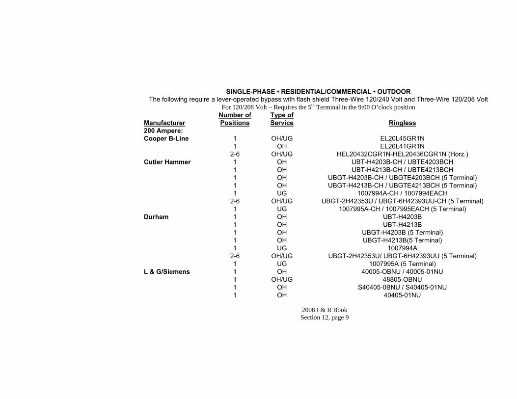
2008 I & R Book Section 12, page 9
SINGLE-PHASE • RESIDENTIAL/COMMERCIAL • OUTDOOR The following require a lever-operated bypass with flash shield Three-Wire 120/240 Volt and Three-Wire 120/208 Volt
For 120/208 Volt – Requires the 5th Terminal in the 9:00 O’clock position Manufacturer
Number of Positions
Type of Service
Ringless
200 Ampere: Cooper B-Line 1 OH/UG EL20L45GR1N 1 OH EL20L41GR1N 2-6 OH/UG HEL20432CGR1N-HEL20436CGR1N (Horz.) Cutler Hammer 1 OH UBT-H4203B-CH / UBTE4203BCH 1 OH UBT-H4213B-CH / UBTE4213BCH 1 OH UBGT-H4203B-CH / UBGTE4203BCH (5 Terminal) 1 OH UBGT-H4213B-CH / UBGTE4213BCH (5 Terminal) 1 UG 1007994A-CH / 1007994EACH 2-6 OH/UG UBGT-2H42353U / UBGT-6H42393UU-CH (5 Terminal) 1 UG 1007995A-CH / 1007995EACH (5 Terminal) Durham 1 OH UBT-H4203B 1 OH UBT-H4213B 1 OH UBGT-H4203B (5 Terminal) 1 OH UBGT-H4213B(5 Terminal) 1 UG 1007994A 2-6 OH/UG UBGT-2H42353U/ UBGT-6H42393UU (5 Terminal) 1 UG 1007995A (5 Terminal) L & G/Siemens 1 OH 40005-OBNU / 40005-01NU 1 OH/UG 48805-OBNU 1 OH S40405-0BNU / S40405-01NU 1 OH 40405-01NU

2008 I & R Book Section 12, page 10
200 Ampere Continued: Manufacturer
Number of Positions
Type of Service
Ringless
L & G/Siemens 2-6 OH/UG 40405X-023NU Midwest Electric 1 OH UBT-H4213B- MEP 1 OH UBGT-H4203B- MEP (5 Terminal) 1 OH UBGT-H4213B-MEP (5 Terminal) 1 UG 1007994A-MEP 1 UG 1007995A-MEP (5 Terminal) 2-6 OH/UG UBGT-2H42353U/ UBGT-6H42393UU-MEP(5 Terminal) Milbank 1 OH U9800-RRL-QG-BL 1 UG U4721-O-BL 2-6 OH/UG U2872-XT-5T9 / U2876-XT-5T9 Murray 1 OH RH173CRJNU 1 OH/UG RH178CRJNU Square D 1 OH UBT-H4203B- SQD 1 OH UBT-H4213B-SQD 1 OH UBGT-H4203B-SQD (5 Terminal) 1 OH UBGT-H4213B-SQD (5 Terminal) 1 UG 1007994A-SQD 1 UG 1007995A-SQD(5 Terminal) 2-6 OH/UG UBGT-2H42353U/ UBGT-6H42393UU-SQD (5Terminal)

2008 I & R Book Section 12, page 11
METER PEDESTALS
For 120/208 Volt – Requires the 5th Terminal in the 9:00 O’clock position Single-Phase • Residential/Commercial ▪ All Outdoor Installations Require Lever-Operated Bypass with Flash Shield
Manufacturer
Number of Positions
Type of Service
Ringless
200 Ampere: Milbank 1 UG U4322-O-BL 2 UG U4323-O-BL
SINGLE-PHASE • RESIDENTIAL/COMMERCIAL • OUTDOOR The following require a lever-operated bypass with flash shield Three-Wire 120/240 Volt and Three-Wire 120/208 Volt
For 120/208 Volt – Requires the 5th Terminal in the 9:00 O’clock position Manufacturer
Number of Positions
Type of Service
Ringless
320 Ampere: Cooper B-Line 1 OH/UG EL32T45GR1N Cutler Hammer 1 OH UBT-H4300T-CH / UBTE4300TCH 1 OH UBT-H4309T-CH / UBTE4309TCH 1 OH/UG 1008068-CH / 1008068ECH 1 OH UBTE4300TCH + MSL5T 1 OH UBTE4309TCH + MSL5T Durham 1 OH UBT-H4300T 1 OH UBT-H4309T 1 OH/UG 1008068 L & G/Siemens 1 OH S9804-9144 1 OH/UG S9804-9146 1 OH/UG 44704-01NU 1 OH 47704-01NU

2008 I & R Book Section 12, page 12
320 Ampere continued: Manufacturer
Number of Positions
Type of Service
Ringless
Midwest Electric 1 OH UBT-H4300T-MEP 1 OH/UG 1008068-MEP 1 OH UBT-H4309T-MEP Milbank 1 OH/UG U4778-X-BL Murray 1 OH RK173AHJNU 1 OH/UG RK178AHJNU Square D 1 OH UBT-H4300T-SQD 1 OH/UG 1008068-SQD 1 OH UBT-H4309T-SQD
SINGLE-PHASE • RESIDENTIAL/COMMERCIAL • OUTDOOR The following require a lever-operated bypass with flash shield Three-Wire 120/240 Volt and Three-Wire 120/208 Volt
Combination Meter Sockets and Disconnect Devices For 120/208 Volt – Requires the 5th Terminal in the 9:00 O’clock position
Manufacturer
Number of Positions
Type of Service
Ringless
100 Ampere: Cooper B-Line 1 OH ECCB10L24A3GR1N Milbank 1 OH U3741-XL-100 Siemens 200 Ampere:
1 OH MM0202L1125RLC
Cooper B-Line 1 OH/UG ELCB20L24A5GR1N 2-6 OH/UG VELMP20432LGRST5K9-VELMP20436LGRST5K9 (vertical) Cutler Hammer 1 OH CMBXB200BTS

2008 I & R Book Section 12, page 13
200 Ampere Continued
1 OH CMBX3242B200BTS Milbank 1 OH U3791N-RXL-200-BL 1 OH/UG U5140-200-BL 2-6 OH/UG U4372-XT-5T9 / U4376-XT-5T9 Siemens 1 OH/UG MM0202L1200RLC 2-6 OH/UG SP4212RJL/SP6612RJL 320 Ampere: Cooper B-Line 1 OH/UG ELCB32C24A5GR1N Milbank 1 OH/UG U4835-X-2\200-BL Siemens 1 OH/UG MC0408B1400RLTM 1 OH/UG MC0816B1400RLTM 1 OH/UG MC0816B1350RLTM 1 OH/UG MM0404L1400RLM 1 OH/UG JA0408B1400RLTM 1 OH/UG JA0816B1400RLTM
THREE-PHASE • COMMERCIAL • OUTDOOR
Must Have Jaw Release Lever-Operated Bypass with Flash Shield All 480Y/277 volt and three-phase 208Y/120 volt network services require main disconnect before meter (cold sequence) Check with CL&P for available fault current before ordering equipment.
Manufacturer
Number of Positions
Type of Service
Four-Wire—Three-Phase 7 Terminal
200 Ampere: Cooper B-Line 1 OH EL20L71GR1N 1 OH/UG EL20L75GR1N Cutler Hammer 1 OH UBT-H7203B or T – CH / UBTE7203BCH

2008 I & R Book Section 12, page 14
1 OH UBT-H7213B or T – CH / UBTE7203TCH 200 Ampere cont. Cutler/Hammer
1 UG 1007996A-CH / 1007996ECH 1 OH UBTE7213BCH / UBTE7213TCH Durham 1 OH UBT-H7203B or T 1 OH UBT-H7213B or T 1 UG 1007996A L & G/Siemens 1 OH 40007-01NU / 40407-01NU 1 OH/UG 48807-02NU 2 - 6 OH/UG 40407X-023NU Midwest Electric 1 OH UBT-H7203B or T - MEP 1 OH UBT-H7213B or T- MEP 1 UG 1007996A-MEP Milbank 1 OH U9700-RRL-QG-BL 1 UG 4910-O-BL Murray 1 OH RH173GRJNU 1 OH/UG RH178GRJNU Square D 1 OH UBT-H7203B or T - SQD 1 OH UBT-H7213B or T- SQD 1 UG 1007996A-SQD

2008 I & R Book Section 12, page 15
THREE-PHASE • COMMERCIAL • OUTDOOR Must Have Jaw Release Lever-Operated Bypass with Flash Shield
All 480Y/277 volt and three-phase 208Y/120 volt network services require main disconnect before meter (cold sequence). Check with CL&P for available fault current before ordering equipment
Manufacturer
Number of Positions
Type of Service
Four-Wire—Three-Phase 7 Terminal
320 Ampere: Cooper B-Line 1 OH EL32T75GR1N Cutler Hammer 1 OH UBT-H7300T-CH / UBTE7300TCH 1 OH/UG 1008069-CH / 1008069ECH Durham 1 OH UBT-H7300T 1 OH/UG 1008069 L & G/Siemens 1 OH S/9804-9145 1 OH S/47707-01NU 1 OH/UG S/9804-9147 Midwest Electric 1 OH UBT-H7300T-MEP 1 OH/UG 1008069-MEP Milbank 1 OH/UG U4911-X-BL Murray 1 OH RK173GHJNU 1 OH/UG RK178GHJNU Square D 1 OH UBT-H7300T-SQD 1 OH/UG 1008069-SQD

2008 I & R Book Section 12, page 16
THREE-PHASE • COMMERCIAL • OUTDOOR (Cont'd) Must Have Jaw Release Lever-Operated Bypass with Flash Shield (may also be used on 100 Ampere)
All 480Y/277 volt and three-phase 208Y/120 volt network services require main disconnect before meter (cold sequence). Check with CL&P for available fault current before ordering equipment
Manufacturer
Number of Positions
Type of Service
Four-Wire—Three-Phase 7 Terminal
200 Ampere: Combination Meter Sockets and Disconnect Devices Cooper B-Line 1 OH/UG ELCB20L27A5GR1N Milbank 1 OH U3781-RXL-200-BL 1 OH/UG U5750-200-BL Siemens 1 OH/UG MM0303B3200RLC

2008 I & R Book Section 12, page 17
THREE-PHASE COMMERCIAL OUTDOOR COLD SEQUENCE COMBINATION METER SOCKETS (BREAKER BEFORE METER)
Must have Jaw Release Lever-Operated Bypass with Flash Shield. All 480Y/277 volt and 208Y/120 volt network services require main disconnect before meter (cold sequence). Check with CL&P for available fault current before ordering equipment. Manufacturer
Number of Positions
Type of Service
Four-Wire-Three-Phase 7 Terminal
200 Ampere: Milbank 1 OH U5767-X-200-CB-BL-NE 1 UG U5787-0-200-CB-BL-NE 320 Ampere: Milbank 1 OH U5796-X-400-CB-BL-NE 1 UG U5799-0-400-CB-BL-NE
GROUP METERING • SINGLE-PHASE • RESIDENTIAL/COMMERCIAL Three-Wire 120/240 Volt and Three-Wire 120/208 Volt 100-Amp Lever-Operated Bypass—200-Amp Lever-Operated Jaw Release Bypass with Flash Shield. Refer to General Requirements for Height Restrictions.
For 120/208 Volt – Requires the 5th Terminal in the 9:00 O’clock position
Ampere Rating Manufacturer Series or
Number Type 100 200 320 Indoor Outdoor
Cutler Hammer 35MM Ringless Yes Yes Yes Yes Yes General Electric Meter Mod III Ringless Yes Yes Yes Yes Yes Murray DL Ringless Yes Yes Yes Yes Yes Siemens W1MM Ringless Yes Yes Yes Yes Yes W2MM Ringless Yes Yes Yes Yes Yes Square D EZM Ringless Yes Yes Yes Yes Yes MPL Meter PAK Ringless Yes Yes No Yes Yes
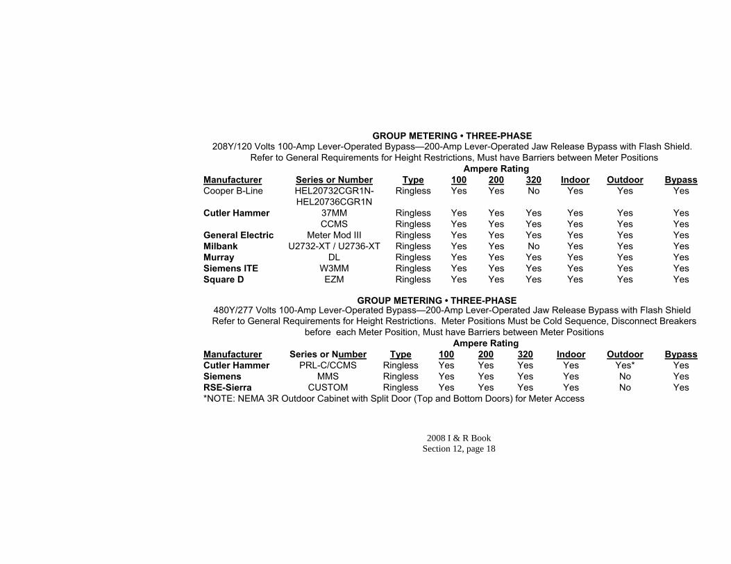
2008 I & R Book Section 12, page 18
GROUP METERING • THREE-PHASE 208Y/120 Volts 100-Amp Lever-Operated Bypass—200-Amp Lever-Operated Jaw Release Bypass with Flash Shield.
Refer to General Requirements for Height Restrictions, Must have Barriers between Meter Positions Ampere Rating Manufacturer Series or Number Type 100 200 320 Indoor Outdoor Bypass Cooper B-Line HEL20732CGR1N- Ringless Yes Yes No Yes Yes Yes HEL20736CGR1N Cutler Hammer 37MM Ringless Yes Yes Yes Yes Yes Yes CCMS Ringless Yes Yes Yes Yes Yes Yes General Electric Meter Mod III Ringless Yes Yes Yes Yes Yes Yes Milbank U2732-XT / U2736-XT Ringless Yes Yes No Yes Yes Yes Murray DL Ringless Yes Yes Yes Yes Yes Yes Siemens ITE W3MM Ringless Yes Yes Yes Yes Yes Yes Square D EZM Ringless Yes Yes Yes Yes Yes Yes
GROUP METERING • THREE-PHASE 480Y/277 Volts 100-Amp Lever-Operated Bypass—200-Amp Lever-Operated Jaw Release Bypass with Flash Shield Refer to General Requirements for Height Restrictions. Meter Positions Must be Cold Sequence, Disconnect Breakers
before each Meter Position, Must have Barriers between Meter Positions Ampere Rating Manufacturer Series or Number Type 100 200 320 Indoor Outdoor Bypass Cutler Hammer PRL-C/CCMS Ringless Yes Yes Yes Yes Yes* Yes Siemens MMS Ringless Yes Yes Yes Yes No Yes RSE-Sierra CUSTOM Ringless Yes Yes Yes Yes No Yes *NOTE: NEMA 3R Outdoor Cabinet with Split Door (Top and Bottom Doors) for Meter Access

2008 I & R Book Section 12, page 19
PRE-WIRED INSTRUMENT TRANSFORMER-RATED SOCKETS WITH PLATED TEST SWITCH Manufacturer 6 Terminal Single Phase Cooper B-Line SW02062S1GR1N Milbank UC7478-O-81-NOE Siemens 9837-0901 Manufacturer 8 TERMINAL—3-PHASE 3-WIRE Milbank UC7444-O-141-NOE Siemens 9837-0902 Manufacturer 13 TERMINAL—3-PHASE 4-WIRE Cooper B-Line SW02132S1GR1N Milbank UC7445-O-311-NOE Siemens 9837-0903 GROUP METERING BARRIERS
Manufacturer Catalog Number Cutler-Hammer 37MMBK General Electric TMBR3 Siemens Contact your local Siemens
Representative Square D MML200BAR

2008 I & R Book Section 12, page 20
600 – 1600 AMP COMBINATION CIRCUIT BREAKER AND INSTRUMENT TRANSFORMER ENCLOSURE 120/240 Volt and 208Y/120 Volt Services, with BAR TYPE Current Transformers. Check with CL&P for available fault current
before ordering equipment Manufacturer Rated Voltage
Interruption Duty Amps Sym @ Rated Voltage
600 Amp
800 Amp
1,000 Amp
1,200 Amp
1,600 Amp Cutler Hammer:
120/240 65,000 WBM WBM - - - 208Y/120 65,000 WBM WBM WBM WBM -
East Coast Power Systems: 120/240 65,000 MBCT65B1 MBCT85B - - -
208Y/120 100,000 MBCT6HB1 MBCT8HB1 MBCT10H81 MBCT12HHB1 MBCT16HHB1 General Electric:
208Y120 42,000 SE46K6 SE46M8 - - - 120/240-208Y/120
65,000
SE46HM6
SE46HM8
SE46HKM10 (208Y/120)
SE46HKM12 (208Y/120)
-
Murray: 120/240 65,000 CBCT636LX CBCT836M6 - - -
208Y/120 100,000 CBCT636HL CBCT836HM CBCT1036HN CBCT1236HN - Siemens ITE:
120/240 65,000 BCT636LXD6 BCT836LMXD6 - - - 208Y/120 100,000 BCT636HLD6 BCT836HMD6 BCT1036HND6 BCT1236HND6 -
Square D: 120/240 65,000 CTC-366CU CTC-368CU - - -
208Y/120 65,000 CTC-366CU CTC-368CU CTC3610CU CTC3612CU - 208Y/120 65,000 QED QED QED QED QED

2008 I & R Book Section 12, page 21
600 – 1600 AMP COMBINATION CIRCUIT BREAKER AND INSTRUMENT TRANSFORMER ENCLOSURE
480Y/277 Volt Services, Cold Sequence, BAR TYPE Current Transformers and Voltage Transformers must be installed in the same compartment. Check with CL&P for available fault current before ordering equipment
Manufacturer/ Rated Voltage
Interruption Duty Amps Sym @ Rated Voltage
600 Amp
800 Amp
1,000 Amp
1,200 Amp
1,600 Amp Cutler Hammer:
480Y/277 65,000 WBM WBM WBM WBM PRL-C 480Y/277 65,000 PRL-C PRL-C PRL-C PRL-C PRL-C
East Coast Power Systems: 480Y/277 35,000 MBCT65B1 - - - - 480Y/277 50,000 MBCT6HB1 MBCT8HB1 MBCT10H81 MBCT1081HB1 MBCT1016HB1 480Y/277 65,000 MBCT6HB1 MBCT8HB1 MBCT10H81 MBCT1081HB1 MBCT1016HB1
General Electric: 480Y/277 30,000 SE46K6PT SE46M8PT SE46KM10PT SE46KM12PT - 480Y/277 35,000 SE46HM6PT SE46HM8PT SE46HKM10P
T SE46HKM12PT -
480Y/277 -
As Specified
Spectra Series AV I, II, III & V
Spectra Series AV I, II, III & V
Spectra Series AV I, II, III & V
Spectra Series AV I, II, III & V
RSE-Sierra 480Y/277 As Specified Custom Custom Custom Custom Custom 480Y/277 As Specified SB SB SB SB SB
Square D
480Y/277 65,000 CTC-366CU CTC-368CU CTC3610CU CTC3612CU - 480Y/277 65,000 QED QED QED QED QED

2008 I & R Book Section 12, page 22
2000/3000 Amp COMBINATION CIRCUIT BREAKER AND INSTRUMENT TRANSFORMER ENCLOSURE
480Y/277 Volt Services, Cold Sequence, WINDOW TYPE Current Transformers and Voltage Transformers must be installed in the same compartment. Check with CL&P for available fault current before ordering equipment
Manufacturer/ Rated Voltage
Interruption Duty Amps Sym @ Rated Voltage
2000/3000 Amp
Cutler Hammer: 480Y/277 As Specified PRL-C
General Electric 480Y/277 As Specified Spectra Series - AV I, II, III & V
Siemens 480Y/277 As Specified SB
Square D: 480Y/277 As Specified QED Series

2008 I & R Book Section 12, page 23
COMBINATION FUSED ENTRANCE SWITCH AND INSTRUMENT TRANSFORMER ENCLOSURE
120/240 Volt and 208Y/120 Volt Services with BAR TYPE Current Transformers Check with CL&P for available fault current before ordering equipment
Manufacturer Rated Voltage 600Amp 800 Amp 1,200 Amp Cutler Hammer 120/240 WSM WSM -
208Y/120 WSM WSM WSM East Coast Power Systems 120/240 MSCT6B1 MSCT8B1 -
208Y/120 MSCT6B1 MSCT8B1 MSCT12B1 General Electric 240 FSE426 FSE428 - Murray 240 FSCT632 FSCT836 - Siemens 240 SCT632 SCT836 - Square D 240 QED QED QED
COMBINATION FUSED ENTRANCE SWITCH AND INSTRUMENT TRANSFORMER ENCLOSURE
480Y/277 Volt Services, Cold Sequence, BAR TYPE Current Transformers and Voltage Transformers must be installed in the same compartment.
Check with CL&P for available fault current before ordering equipment Manufacturer Rated Voltage 600Amp 800 Amp 1,200 Amp Cutler Hammer 480Y/277 CCMS CCMS CCMS East Coast Power Systems 480Y/277 MSCT46B1 MSCT48B1 MSCT412B1 General Electric 480Y/277 FSE446PT FSE448PT FSE4412GFPT Murray 480Y/277 SB SB SB Siemens 480Y/277 SB SB SB Square D 480Y/277 QED QED QED In addition to 480 volt services any 600 volt services must have integral mounting provisions in the instrument transformer compartment for current transformer and voltage transformers.
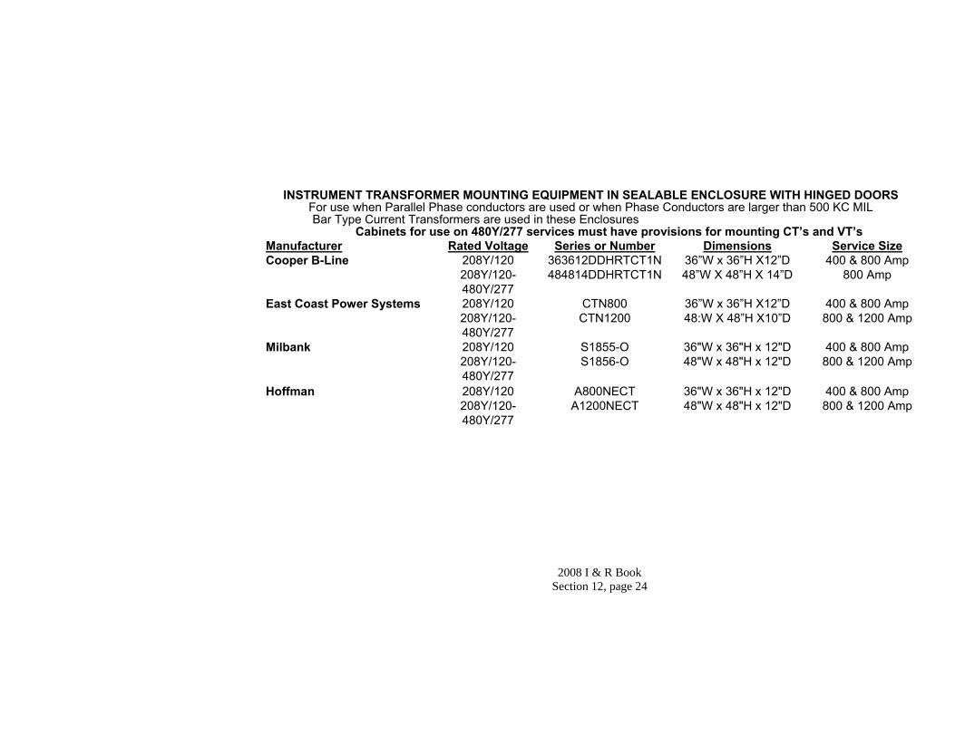
2008 I & R Book Section 12, page 24
INSTRUMENT TRANSFORMER MOUNTING EQUIPMENT IN SEALABLE ENCLOSURE WITH HINGED DOORS For use when Parallel Phase conductors are used or when Phase Conductors are larger than 500 KC MIL Bar Type Current Transformers are used in these Enclosures
Cabinets for use on 480Y/277 services must have provisions for mounting CT’s and VT’s Manufacturer Rated Voltage Series or Number Dimensions Service Size Cooper B-Line 208Y/120 363612DDHRTCT1N 36”W x 36”H X12”D 400 & 800 Amp 208Y/120-
480Y/277 484814DDHRTCT1N 48”W X 48”H X 14”D 800 Amp
East Coast Power Systems 208Y/120 CTN800 36”W x 36”H X12”D 400 & 800 Amp 208Y/120-
480Y/277 CTN1200 48:W X 48”H X10”D 800 & 1200 Amp
Milbank 208Y/120 S1855-O 36"W x 36"H x 12"D 400 & 800 Amp 208Y/120-
480Y/277 S1856-O 48"W x 48"H x 12"D 800 & 1200 Amp
Hoffman 208Y/120 A800NECT 36"W x 36"H x 12"D 400 & 800 Amp 208Y/120-
480Y/277 A1200NECT 48"W x 48"H x 12"D 800 & 1200 Amp

2008 I & R Book - Section 13 Page 1 -
SECTION 13: Index A Section Item Page Access 1 G 5 AMR (Definition) Antennas 1 A.10 2 Approvals 1 C.1 3 Approved Metering Equipment 12 B Banners 1 A.11 2 C Campgrounds 4 A.3.b 1 Checklist:
New Services 12 6 Service Changes (Upgrades) 12 7 Instrument Transformer 12 8
Clearance 3 D.1.a 1 Clearing Desk (Definitions) Codes (Definitions) Conduit System (Definition) Connections (Meter Socket) 8 I.3 Connections (to our facilities) 5 A.4 1 Cost of Service Facilities 5 A.4 1 Cover Plates 8 F Current Transformers 8 J Cut and Reconnect 2 D Damage to Meters 8 H.1.c Definitions Demolition 5 F.1 2 Digging 1 A.3 1 Disconnecting 5 D 2 Disconnecting Service 5 D 2

2008 I & R Book - Section 13 Page 2 -
Section Item Page E Emergency Generation 10 A 1 Employee Identification 1 J 6 Extended Metering Options 8 K F Fire Pumps 6 B.6 2 Frequency (See Hertz) 4 A.1 1 Fuse Main 6 C.1 2 G Ground Faults 1 A.8 1 Grounding 8 E Group Metering 8 H.4 H Hertz 4 A.1 1 I Identification:
Employee 1 K 6 Contractor/Electrician 6 E 3
Inspections 1 J 6 Instrument Transformers 8 J Interrupter, Ground Fault 1 A.8 1 L Lateral (Definition) Limiter 6 B.4 1 Load Pulse Outputs 8 K.2 Location Weatherhead 3 D 1-2 M Main Fuse 6 C.1 2 Marinas 8 H.6

2008 I & R Book - Section 13 Page 3 -
Section Item Page Meter(s) Installation: 8 B Location 8 C Grouped 8 H.4 Sockets 8 D.4 Sequence (Definition) Sequence 8 H.2 Mobile Homes 8 H.6 Motors 9 B-D 1-3 Metering Transformers 8 J (See Instrument Transformers) N Number of Services 5 C 1-2 O Office Locations Our (Definition) Our Service Facilities 5 Overhead Service from 3 D 1-2 Overhead System P Phone Automatic Meter Reading 8 K.1 Pole-Mounted Service 6 D 3 Power Factor 9 E 3 Primary Service 3 C 1 Private Property 1 E 2 R Recording Meter 8 K.4 Request for Electric Service 1 B 2 Residential Cut and Reconnect Policy 2 Removal of Service at Your Request 4 F 2

2008 I & R Book - Section 13 Page 4 -
Section Item Page S Safety: The First Priority 1 A 1-2 Service: Network (Definition) Service: Primary (Definition) Service: Secondary (Definition) Service Drop (Definition) Service Entrance Conductors 6 C 2 Service Equipment 6 B 1-2 Service Facilities (Ours) 5 Service Facilities (Yours) 6 Service Lateral (Definition) Service Location (Definition) Service Location 6 A 1 Service Changes 1 H 5 Supply Characteristics 4 A 1-2 Self-Contained Single-Phase 8 H Meter Installations Self-Contained Three-Phase 8 I Meter Installations Sequence of Meter and Service 8 H.2 Equipment Single-Phase Sequence of Meter and Service 8 I.2 Equipment Three-Phase Slip Meter Riser (Definition) Special Request Metering 8 K.3 Suitable Backfill (Definition) Swimming Pools 1 A.7 1 T Temporary Service 1 D 3 Third Party Communication Companies’ 7 Attachments to CL&P Distribution Facilities Tree Trimming 3 D.1.d 3 Types of Secondary Service 3 D 1-2 Two-Phase Supply 4 C 3

2008 I & R Book - Section 13 Page 5 -
Section Item Page U Underground Manhole System (Definition) Unusual Conditions 1 B 2 Uninterruptible Power Supply 10 C 2 V Violations (Cut & Reconnect Policy) 2 Voltage, Nominal 4 3 1 W We (Definition) xvii Wiring Trough 8 H.4 X X-Ray Equipment 9 A 1 Y You (Definition) Your (Definition)

2008 I & R Book - Section 13 Page 6 -
This checklist is provided as a quick reference to help you successfully complete a project.
For New Services: Have you:
□ Submitted a “Request for Electric Service” via phone, internet, mail or in person
□ Obtained all local permits □ Received approval for custom, combination or instrument
transformer metering equipment □ Discussed the routing and location of the service with a
technician □ Discussed the need for steel sweeps in the conduit system (if
applicable) □ Coordinated with other utilities □ Received an approved meter location □ Paid all applicable charges, if required □ Notified Call Before You Dig (if applicable) □ Installed service entrance equipment □ Installed an approved meter socket with optically clear cover □ For a conduit system, installed a slip joint, sweeps, conduit
and ¼” pulling line □ For a conduit system where steel sweep(s) are required,
install a ground to the sweep at the meter location □ Permanently marked each meter socket and load disconnect
with its unique identification. □ Establish a safe work space in front of each meter location □ Called the local inspecting authority for inspection/approval.

2008 I & R Book - Section 13 Page 7 -
For Service Changes Have you:
□ Confirmed that service locations and meter locations meet requirements of this booklet
□ Submitted a “Request for Electric Service” via phone, internet, mail or in person
□ Obtained all local permits □ Received approval for custom, combination or instrument
transformer metering equipment □ Discussed the need for steel sweeps in the conduit system (if
applicable) □ Received an approved meter location (if applicable) □ Paid all applicable charges, if required □ Notified Call Before You Dig (if applicable) □ Installed service entrance equipment □ Installed an approved meter socket with optically clear cover □ For a conduit system, installed a slip joint, sweeps, conduit
and ¼” pulling line □ For a conduit system where steel sweep(s) are required,
install a ground to the sweep at the meter location □ Permanently marked each meter socket and load disconnect
with its unique identification. □ Establish a safe work space in front of each meter location □ Called the local inspecting authority for inspection/approval.

2008 I & R Book - Section 13 Page 8 -
Checklist for Instrument Transformer Rated Installations Have you:
□ Barrel locked sealing device for main disconnect. □ Approved instrument transformer enclosure. □ Barrel locked sealing device for instrument transformer
enclosure □ Equipment grounds must be installed. □ Approved, pre-wired combination meter socket and test
switch is permanently mounted. □ Conduit installed between meter socket and CT
compartment. □ If using PVC conduit, a separate bonding wire is installed
according to code. □ CTs/PTs properly mounted and secured; If bar-type, CT’s
are properly torqued. □ CT’s are located on load side of main switch (cold sequence)
unless CL&P has granted an exception. □ A #4 Burndy lug (or equivalent) has been installed. □ for equipment (case) ground inside transformer
compartment. □ for neutral connection in transformer cabinet, wired to
neutral bus □ on each phase bus, line side of CT (window-type CTs)
When all the above items have been completed, call local CL&P office to schedule wiring. Please consult CL&P’s Information and Requirements booklet (Section 7 for information on Instrument Transformer Metering Requirements.

2008 I & R Book - Section 13 Page 9 -
NOTES: ________________________________________ ________________________________________ ________________________________________ ________________________________________ ________________________________________ ________________________________________ ________________________________________ ________________________________________ ________________________________________

ELECTRICAL CONTRACTORS Your “Service Requests” are only a >CLICK< away!
Quick and Easy * Self Serve * Convenient and Secure
Electrical Contractors are in control with CL&P’s online Request for Electric Service system. Contractors can initiate, submit and monitor the status of a particular request for CL&P electric service, anytime, at www.cl-p.com. Each electric service request is assigned a unique identification number allowing you to monitor the progress of each service requests. You can:
View CL&P’s planned scheduled date. View the status on job requirements such as municipal
inspection approvals and easements. Identify the CL&P Job Designer assigned to the request. Access all of your requests for electric service 24/7.
Registering is free and easy.
1. Visit “For My Business” on www.cl-p.com. 2. Click on Service Request for Contractors 3. Follow instruction on “How to Register”.
Request for Electric www.cl-p.com
For assistance or more information, call CL&P’s New Service Clearing Desk at 1-888-LIGHTCO (1-888-544-4826) or email us at:


![NES Turkey Ordu Hazelnut 2013[3] - Fair Labor Association · 3& & CL.1&General&Compliance&Child&Labor& Noncompliance& p.&13& CL.2&ChildLabor& Noncompliance& p.&14& CL.3&Proof&of&AgeDocumentation&](https://img.dokumen.tips/doc/110x75/5f026fd87e708231d404424f/nes-turkey-ordu-hazelnut-20133-fair-labor-association-3-cl1generalcompliancechildlabor.jpg)