Embed Size (px)
Citation preview

CLP-TN-G-011-SABC
Iss.1 Rev.0
Date: 01/09/2016
Page : 1/17
This document has been issued by Société Anonyme Belge de Construction Aéronautique (Belgium) - All information contained in this document is exclusive
property of SABCA SABCA Brussels – All rights reserved Don't print this document unless it's really necessary
Category: 4 Class: 2
Prepared by: M. Ruiz 08/09/16
Approved by:
P. Lenelle
08/09/16
Authorised by:
M. Ruiz
08/09/16
CLP PROGRAM
CLP Executive Summary Report

CLP-TN-G-011-SABC
Iss.1 Rev.0
Page : 2/17
This document has been issued by Société Anonyme Belge de Construction Aéronautique (Belgium) - All information contained in this document is exclusive
property of SABCA SABCA Brussels – All rights reserved Don't print this document unless it's really necessary
Issued by : SABCA Contractual : Yes (X) No () Date : 01/09/2016
Customer : ESA Contract Number: 4000107720/12/NL/LvH
TITLE : CLP Executive Summary Report AUTHOR: ruiz AUTHOR'S ABSTRACT: This document presents the CLP Executive summary report of the Phase 1 of the CLP program
TOTAL NUMBER OF PAGES: 17 - Number of Annexes : n/a
File Identification : CLP-TN-G-011-SABCLAR1r0.docx
Distribution Key Words
Internal External CLP, ASIC, processor, real-time Dept. N° Cop. Names Dept./Company N° Cop. Names
Document’s signatories ESA/ESTEC 1 R. Weigand
CLP team ESA/ESTEC 1 L. Van Hilten
K. Vekemans

CLP-TN-G-011-SABC
Iss.1 Rev.0
Page : 3/17
This document has been issued by Société Anonyme Belge de Construction Aéronautique (Belgium) - All information contained in this document is exclusive
property of SABCA SABCA Brussels – All rights reserved Don't print this document unless it's really necessary
ISSUE / REVISION STATUS
Date Iss./Rev.
N° Brief Description of Change
Mod. N°
ECP/PM N°
Config. Control Approval
01/09/2016 1/0 First Issue

CLP-TN-G-011-SABC
Iss.1 Rev.0
Page : 4/17
This document has been issued by Société Anonyme Belge de Construction Aéronautique (Belgium) - All information contained in this document is exclusive
property of SABCA SABCA Brussels – All rights reserved Don't print this document unless it's really necessary
TABLE OF CONTENTS
1 INTRODUCTION AND ABSTRACT ................................................................................................. 5
2 DOCUMENTS AND ACRONYMS ................................................................................................... 5
2.1 APPLICABLE DOCUMENTS ................................................................................................................. 5 2.2 REFERENCES .................................................................................................................................. 5 2.3 ACRONYMS ................................................................................................................................... 6
3 OVERVIEW OF THE ACTIVITY ....................................................................................................... 7
4 OUTCOME .................................................................................................................................. 8
4.1 CONTROL LOOP PROCESSOR ....................................................................................................... 8 4.2 SOFTWARE DEVELOPMENT ENVIRONEMENT ............................................................................. 10 4.3 VALIDATION CAMPAIGN ........................................................................................................... 12 4.4 ASIC TECHNOLGY ......................................................................................................................... 13
5 RETURN OF EXPERIENCE ........................................................................................................... 14
5.1 SUBCONSTRACTORS ................................................................................................................. 14 5.2 LESSONS LEARNED ................................................................................................................... 14
6 DELIVERABLES .......................................................................................................................... 15
6.1 DOCUMENTS ............................................................................................................................ 15 6.2 HARDWARE ............................................................................................................................. 16 6.3 SOFTWARE ............................................................................................................................... 16
7 CONCLUSIONS .......................................................................................................................... 17

CLP-TN-G-011-SABC
Iss.1 Rev.0
Page : 5/17
This document has been issued by Société Anonyme Belge de Construction Aéronautique (Belgium) - All information contained in this document is exclusive
property of SABCA SABCA Brussels – All rights reserved Don't print this document unless it's really necessary
1 INTRODUCTION AND ABSTRACT
Nowadays, the field of tight control loops, characterized by hard real-time constraints (loop
frequency > 1 kHz) in conjunction with complex algorithmic needs, currently lacks a microprocessor
allowing to make a software programmable approach economically and technically viable. The
control of electro-mechanical actuators is an example of target application.
A dedicated space-hardened microprocessor, called Control Loop Processor (CLP), has been designed
in this activity and integrates several key features ensuring a fully deterministic behaviour as well as
an embedded robustness/anomaly management in conjunction with vectorial IEEE-754 floating-
points operations. A wide range of interfaces have also been selected to cover current and future
space-oriented interfaces.
A software development environment has been defined during the activity to deal with the need of
future users. In particular, the development of a C compiler and a code generator taking Simulink as
code source is envisaged. This activity allowed designing a first version of the assembler, the
Simulink macro library and the ISS, based on a cycle-accurate SystemC model
2 DOCUMENTS AND ACRONYMS
2.1 APPLICABLE DOCUMENTS
[AD1] 4000107720-13-NL-LvH GSTP Contract GSTP Contract – Control Loop Processor (Phase 1)
[AD2] ECSS-Q-ST-60-02C Space Product Assurance, ASIC and FPGA development
2.2 REFERENCES
[RD1] CLP-DVP-C-001-SABC CLP Development Plan
[RD2] CLP-DJ-C-001-SABC CLP Feasibility and Risk analysis
[RD3] CLP-TN-C-001-SABC CLP Requirements Specification
[RD4] CLP-VP-C-001-SABC CLP Verification Plan
[RD5] CLP-COP-C-001-SABC CLP Control Plan

CLP-TN-G-011-SABC
Iss.1 Rev.0
Page : 6/17
This document has been issued by Société Anonyme Belge de Construction Aéronautique (Belgium) - All information contained in this document is exclusive
property of SABCA SABCA Brussels – All rights reserved Don't print this document unless it's really necessary
2.3 ACRONYMS
A5ME Ariane 5 Midlife Evolution
ADC Analog to Digital Converter
AWG Arbitrary Waveform Generator
BIST Built In Self Test
CLP Control Loop Processor
CPU Central Processing Unit
DRD Document Requirements Description
DSP Digital Signal Processor
EDAC Error Detection And Correction
EEPROM Electrically Erasable Programmable Read Only Memory
EGPIO Extended GPIO
FPGA Field Programmable Gate Array
GPIO General Purpose Inputs Outputs
GSTP General Support Technology Program
HBRISC Hardened Bi Reduced Instruction Set Computer
HW HardWare
I2C Inter Integrated Circuit
ISS Instruction Set Simulator
ITAR International Traffic in Arms Regulation
JTAG Joint Test Action Group
KLOC Kilo Lines Of Code
LSB Least Significant Bit
LVDS Low Voltage Differential Signalling
LVDT Linear Variable Differential Transformer
MAC Media Access Controller
MSB Most Significant Bit
PWM Pulse Width Modulation
RT Remote Terminal
SEL Signal Event Latch-up
SEU Single Event Upset
SIMD Single Instruction Multiple Data
SPI Serial Peripheral Interface
SRAM Static Random Access Memory
SW SoftWare
TVC Thrust Vector Control

CLP-TN-G-011-SABC
Iss.1 Rev.0
Page : 7/17
This document has been issued by Société Anonyme Belge de Construction Aéronautique (Belgium) - All information contained in this document is exclusive
property of SABCA SABCA Brussels – All rights reserved Don't print this document unless it's really necessary
3 OVERVIEW OF THE ACTIVITY
This activity has covered the phase 1 of the whole CLP development. A number of trade-offs and studies have been performed to analyze and propose:
o A processor architecture that is in line with the targeted needs, derived from the HBRISC2 device and the work made during HBRISC3 activities. The selection of the IPs has also been performed
o A list of SDE tools to support the full V-cycle SW development, based on well-known tools
o An analysis of the feasibility of the DARE180 ASIC technology with respect to the CLP characteristics, including analog functions
The activity has been closed with PDR acknowledging:
o The development of the CLP RTL code, based on its specification
o Development of a cycle accurate SystemC model allowing the co-validation with the VHDL code and a solid basis for the ISS
o A complete suite of automated testbenches allowing the validation of the CLP RTL code by simulation and via FPGA prototyping (based on Cobham Gaisler RASTA system).
o A preliminary version of the CLP assembler and unit test manager. A first version of the macro library has also been developed
o A preliminary business plan

CLP-TN-G-011-SABC
Iss.1 Rev.0
Page : 8/17
This document has been issued by Société Anonyme Belge de Construction Aéronautique (Belgium) - All information contained in this document is exclusive
property of SABCA SABCA Brussels – All rights reserved Don't print this document unless it's really necessary
4 OUTCOME
This section provides a detailed overview of the phase 1 main outputs constituted of the CLP, its SDE items and the ASIC feasibility.
4.1 CONTROL LOOP PROCESSOR
The Control Loop Processor is made of two CPUs
(drawn in blue and read) and a number of
peripherals (surrounded by an orange box).
Each CPU is based on a RISC architecture and
cache-free topology to provide a fully
deterministic behaviour. No interruptions is
foreseen. It is made of three arithmetic units.
Two of them are floating-point units and the last
one is a 16-bit integer unit. The floating-point
units integrate the IEEE-754 format in single
precision. Various SIMD instructions are available
to parallelize computations. The CLP target speed
is 50 MHz thus providing up to 200 MFLOPs peak
performance when the 4 FPUs are fully occupied. Each CPU contains a 32kx39 program memory,
called PRAM, which is also available for data through the APB bus controlled by the CPU. Each CPU
integrated 2x512 general-purpose registers in floating-point units and 32 general-purpose registers
in the SU unit. A stack pointer is also available with an on-chip integration of stacks (using general-
purpose registers). Each CPU contains a DMA. This unit allows to off-load the software from
transfers occurring between the CPU registers and any APB peripherals. The communication
between the two CPUs is possible through an 1kx39-bit wide INTERCOM RAM.
Two on-chip busses, based on the APB AMBA standard, are available. Each CPU has its own bus to
interact with peripherals and has the master role. Each peripheral is thus exclusively slave. An
allocation and write protection mechanism is integrated to program, at boot time, which APB
register or segment is allocated to which CPU. When the software is running, this configuration is
static thus ensuring a deterministic communication between the CPUs and the peripherals. Any
abnormal access is detected and reported in a dedicated counter.
10 on-chip Timers are available for use by the CPUs or most of the various on-chip peripherals.
These timers constitute the nerve of the CLP as they allow to synchronise the software running of
the CPUs with the used peripherals. Two SPI interfaces are included and can be programmed in
either master or slave mode. The data acquisition can be either sequential or made in parallel. This
interface is particularly interesting when working with serial off-chip ADCs. A PWM interface is
integrated allowing to drive up to 2x24 signals. Each output has its complement thus easing the
UDP/IP
CLP
PWM
(x24)
GPIO
(x32)
TIMERS
(x10)
SPI
(x12)
I2C
ADC
INTERFACE
Ed9 Rev2
UART
(x4)
CRC
UNIT
(x2)
INTERCOM
RAM
C
P
U
1
REAL-TIME
BACKGROUND
TRACER
REGISTERS
FILE
IEEE-754
32-bit
FPU/IU
REGISTERS
FILE
A UNIT B UNITSU UNIT
EDAC
REGISTERS
FILE
IEEE-754
32-bit
FPU/IU
EDAC
16-bit
IU
DMA REGS
SPACEWIRE
#1
MIL-STD-1553
RT
SPACEWIRE
#2CAN
PERIPHERALS
WAVEFORM
GENERATOR
AMBA APB CORE 1
APB MASTER
C
P
U
2
PROGRAM/DATA
MEMORY
EDAC
CPU PIPELINE MANAGEMENT
CORE 1
XCHG
RAM
CORE 2
XCHG
RAM
AM
BA
AH
B
M M M
AMBA AHB
AMBA APB CORE 1
AMBA APB CORE 2
BOOT
MANAGER
EDAC
S
S
S
S
S
S
S
S
S
S
S
S
S
S
S
S
S
S
S
S
M
MMU
CO
NF
IG
S
S
S
S
IOMUX
CONFIG
MS
S
M
BO
OT
CO
NF
IG
M
DMA REGS
ED
AC
DMA

CLP-TN-G-011-SABC
Iss.1 Rev.0
Page : 9/17
This document has been issued by Société Anonyme Belge de Construction Aéronautique (Belgium) - All information contained in this document is exclusive
property of SABCA SABCA Brussels – All rights reserved Don't print this document unless it's really necessary
generation of signals intended for power electronics. Two AWG are available to automatically
generate any arbitrary waveform. The typical use of these AWG are either performing sensors
excitation or some sort of analog reporting. A parallel ADC interface is included to allow interacting
with any off-chip parallel interface. The polarity and timings are fully programmable. Up to 4 off-chip
devices can be addressed and 16 samples transferred per acquisition (which is triggered by one of
the CLP timers). The ADC interface is autonomous. Four UARTs are included to interface any off-chip
device with the CLP. The baud rate is programmable and either 8-bit or 32-bit mode available. The
CLP also integrates one I2C interface to interact with upcoming space devices which make use of this
standard. Two CRC units are available to perform any data integrity check. The polynomial is fully
programmable. 96 GPIOs are available either in the conventional mode (input, output or
input/outputs) or in a MEM8 mode allowing to automatically interact with an external 8-bit memory.
These GPIOs are multiplexed with other interfaces in the IOMUX pins.
A Spacewire-RMAP, MIL-STD-1553 RT and CAN interfaces are included to support most space
applications needs. All these interfaces comply with their respective standards are interact with the
software through two exchange RAMS. One CPU has its dedicated XCHG_RAM which is 8Kx39 bits
wide. An MMU performs the routing from/to these XCHG_RAMs from/to the mentioned interfaces.
The MMU can be programmed by the software through descriptors. An allocation mechanism is also
foreseen to filter data handled by a given interface.
The software is debugged and validated through the RTBT link. This interface is based on the 100
Mbits/s Ethernet/UDP standard and allows to perform real-time tracing of CPUs registers, APBs
traffic, MMU interactions and PRAMs activity. The RTBT is not intrusive and does not need
instrumentation code thus making it suitable for applications forbidding useless code.
The CLP is fault-tolerant against any SEU occurring in its whole memory space. EDAC management in
integrated to perform “on-the-fly” correction in case of read and an on-chip write-back correction to
avoid errors accumulation. A scrubbing unit is also foreseen with a programmable refresh rate and
correction address range. The fault tolerance also applies to any abnormal event occurring inside the
CLP such as a deadlock condition in the ADC interface, an allocation violation detected by the MMU,
a saturation condition occurring in an arithmetic unit or an illegal operand detection.
Finally, a boot manager is included which provides a robust boot and restart mechanism through 4
boot descriptors. 5 boot sources can be programmed (RMAPx2, CAN, MEM8 or RTBT) to
automatically upload these boot descriptors and then boot the whole CLP according to the content
of these ones.
In the scope of phase 1, the CLP VHDL code has been fully developed.

CLP-TN-G-011-SABC
Iss.1 Rev.0
Page : 10/17
This document has been issued by Société Anonyme Belge de Construction Aéronautique (Belgium) - All information contained in this document is exclusive
property of SABCA SABCA Brussels – All rights reserved Don't print this document unless it's really necessary
4.2 SOFTWARE DEVELOPMENT ENVIRONEMENT
The SDE user interface is based on two
standard tools which are commonly used in
space applications:
Matlab/Simulink to graphically design the application with built-in entry methods and perform simulation
Eclipse which is an open-source framework giving a user-friendly interface to all the SDE items that will be developed
The SDE generator is intended to produce an intermediate level model from the high-level model
that has been designed by the front-end tool. The generated model is compliant with format defined
by LLVM library and can thus be used as an entry by the SDE compiler. The SDE generator will make
use of the off-the-shelf Qgen tool, provided by ADACORE company.
The SDE compiler is intended to produce a target independent low-level model from a model
described with C standard. It can also read an intermediate-level model which is compliant with
LLVM format. The generated code can be as an entry for the SDE assembler. The choice of the LLVM
library is motivated by the various trade-offs that have been made during the phase 1 of the project.
No license or fee is needed to access this library.
The SDE assembler is intended to produce a binary code from a low-level representation model. A
first prototype has been designed for this tool and is available on request. It is intended to update
and enhance the development with a number of additional utilities such as a configurator allowing a
user to initialise the CLP peripherals and CPU(s) in a friendly fashion, a loader allowing the user to
download the binary code into the CLP board, an assembly editor based on Eclipse.
The SDE debugging tool is intended to support the user to test, debug and validate an application
running on the CLP. Four items are foreseen: the unit test manager giving a basic infrastructure to
the user to develop unit test campaigns on CLP assembly code, the tracer allowing to program and
track all reporting information to/from the RTBT unit inside the CLP, the ISS based on the cycle-
accurate CLP SystemC model, the debugger allowing the user to interactively debug a given CLP code
by means of various intrusive functions. The debugger will make use of the SystemC model whose
behaviour is ensured to be equivalent to the CLP because of the all the co-validation and co-
simulations made during phase 1.
When a CLP application is designed by mean of the Matlab-Simulink tool, two approaches are
possible. The user may use the standard library available within the environment (i.e. S-function, and
USER INTERFACE
GENERATOR COMPILER
ASSEMBLER
DEBUGGER
CLP
SDE environmentMACRO
LIBRARY

CLP-TN-G-011-SABC
Iss.1 Rev.0
Page : 11/17
This document has been issued by Société Anonyme Belge de Construction Aéronautique (Belgium) - All information contained in this document is exclusive
property of SABCA SABCA Brussels – All rights reserved Don't print this document unless it's really necessary
so on…) or a dedicated library made of custom blocks coupled to CLP assembler code or a mix of
both approaches. To support the user in this second alternative, a library with a number or
predefined CLP macros including commonly used high-level functions will be developed and cover,
for instance, more complex mathematical functions such as filters and basic drivers functions
allowing to simplify the communication with the CLP interfaces (PWM, MIL-STD-1553, etc …).
In the scope of phase 1, the SDE assembler and the CLP macro libraries have been developed and are
available in preliminary version. The de-risking activities ensuring the successful development of
remaining SDE items (during phase 2A and phase 3) has also been performed.
CLP-TN-G-011-SABC
Iss.1 Rev.0
Page : 12/17
This document has been issued by Société Anonyme Belge de Construction Aéronautique (Belgium) - All information contained in this document is exclusive
property of SABCA SABCA Brussels – All rights reserved Don't print this document unless it's really necessary
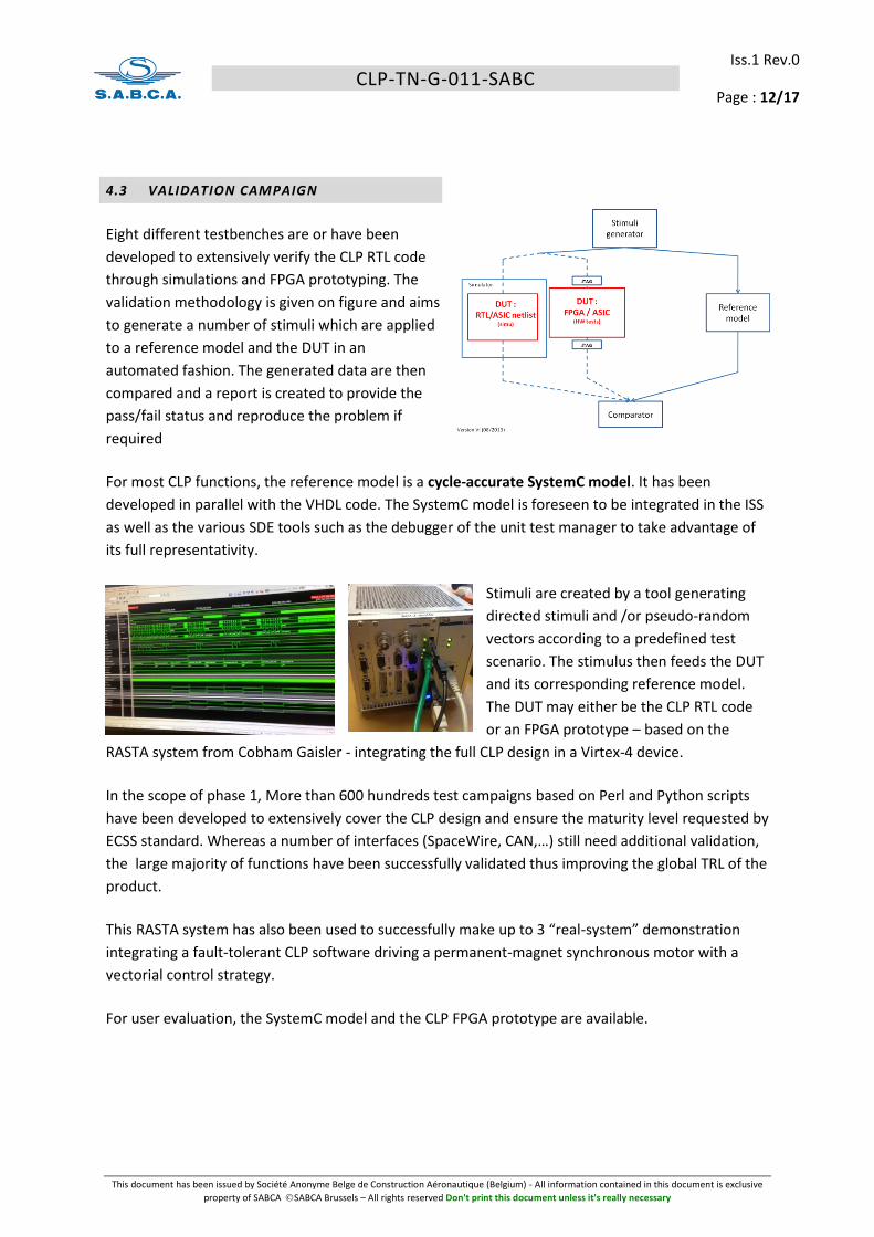
4.3 VALIDATION CAMPAIGN
Eight different testbenches are or have been
developed to extensively verify the CLP RTL code
through simulations and FPGA prototyping. The
validation methodology is given on figure and aims
to generate a number of stimuli which are applied
to a reference model and the DUT in an
automated fashion. The generated data are then
compared and a report is created to provide the
pass/fail status and reproduce the problem if
required
For most CLP functions, the reference model is a cycle-accurate SystemC model. It has been
developed in parallel with the VHDL code. The SystemC model is foreseen to be integrated in the ISS
as well as the various SDE tools such as the debugger of the unit test manager to take advantage of
its full representativity.
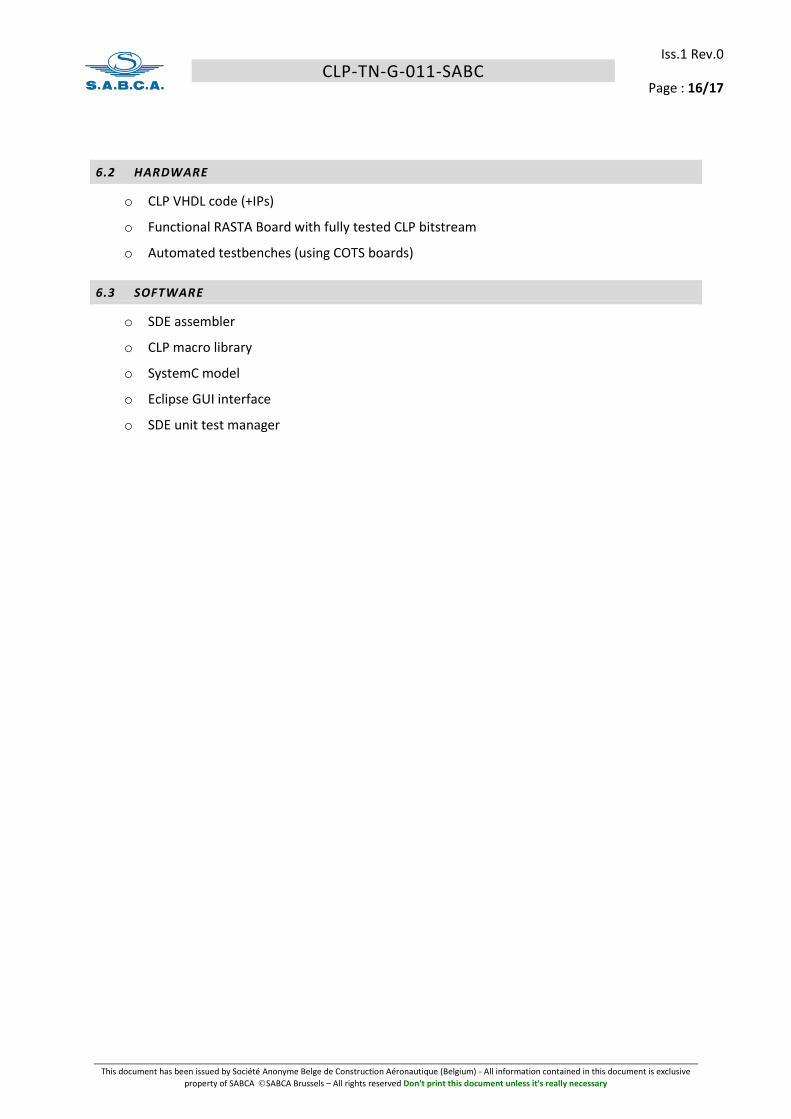
Stimuli are created by a tool generating
directed stimuli and /or pseudo-random
vectors according to a predefined test
scenario. The stimulus then feeds the DUT
and its corresponding reference model.
The DUT may either be the CLP RTL code
or an FPGA prototype – based on the
RASTA system from Cobham Gaisler - integrating the full CLP design in a Virtex-4 device.
In the scope of phase 1, More than 600 hundreds test campaigns based on Perl and Python scripts
have been developed to extensively cover the CLP design and ensure the maturity level requested by
ECSS standard. Whereas a number of interfaces (SpaceWire, CAN,…) still need additional validation,
the large majority of functions have been successfully validated thus improving the global TRL of the
product.
This RASTA system has also been used to successfully make up to 3 “real-system” demonstration
integrating a fault-tolerant CLP software driving a permanent-magnet synchronous motor with a
vectorial control strategy.
For user evaluation, the SystemC model and the CLP FPGA prototype are available.

CLP-TN-G-011-SABC
Iss.1 Rev.0
Page : 13/17
This document has been issued by Société Anonyme Belge de Construction Aéronautique (Belgium) - All information contained in this document is exclusive
property of SABCA SABCA Brussels – All rights reserved Don't print this document unless it's really necessary
4.4 ASIC TECHNOLGY
The feasibility performed on the DARE180 ASIC technology has been base on a trial synthesis made
on the full CLP VHDL design. The work led to the following results:
o Maximal frequency: 58 MHz in pre-layout conditions (hardened HIT scan cells have been selected)
o Die area: around 14 mm x14mm (routing, pads, JTAG and scan logic excluded), a large part of the design being made of RAM cells.
These figures led to consider other alternatives to the DARE180 since yield and consumption issues
were considered as likely thus impacting the CLP potential. Note also that significant work has been
made to assess the possibility of integrating analog functions (ADCs, DAC,…) but no relevant solution
was found.
It is today foreseen to target the CLP design on the DARE65 ASIC technology which is currently under
development by IMEC. Further analysis will have to be made in the future.
Note also that FPGA variants are available with the current definition of the CLP.

CLP-TN-G-011-SABC
Iss.1 Rev.0
Page : 14/17
This document has been issued by Société Anonyme Belge de Construction Aéronautique (Belgium) - All information contained in this document is exclusive
property of SABCA SABCA Brussels – All rights reserved Don't print this document unless it's really necessary
5 RETURN OF EXPERIENCE
5.1 SUBCONSTRACTORS
The SDE has been led by Spacebel (Belgium). The implication and availability of the technical team
has been appreciated. Their knowledge and involvement allowed preparing and de-risking the
development activities that are part of the phase 2A.
The ASIC feasibility has been by IMEC. The contact was excellent and technical work has been
appreciated. Their honesty has also being valued despite the fact the DARE180 has been considered
as not optimal.
The selected IPs (SpaceWire/RMAP, MIL-STD-1553 RT, CAN, SPI, I2C and Ethernet) were provided by
Gaisler. The helpdesk was very reactive and the documentation very good despite a few
uncertainties on details. The IP integration inside the CLP design was made with no particular
problem.
5.2 LESSONS LEARNED
The validation methodology proposed by SABCA was challenging and led to a product with a very
good level of maturity. The co-validation with the SystemC was the good approach even though the
fact that that man-effort needed to align the VHDL, the SystemC and the specification (up to the
cycle level for some parts) should not be neglected in a future project.
The automated testbenches, in addition to their key role in the validation campaign, also allowed to
monitor the maturity of the product thanks to the non-regression tests settled early in the
development and executed every night. This point allowed to make early trapping of VHDL and
SystemC regressions during bug resolution made during the day.
The use of pseudo-code to pre-design and document the extensive number of tests that were
foreseen during this activity was a good approach. However, the use of either textual descriptions or
standard languages (perl, python,…) is preferable.
The use of Eclipse and open-source tools (Git and Mantis) to perform design and bug management
on the VHDL, SystemC, validation scripts and testbenches has clearly provided an added value to the
overall project quality.

CLP-TN-G-011-SABC
Iss.1 Rev.0
Page : 15/17
This document has been issued by Société Anonyme Belge de Construction Aéronautique (Belgium) - All information contained in this document is exclusive
property of SABCA SABCA Brussels – All rights reserved Don't print this document unless it's really necessary
6 DELIVERABLES
The following deliverables have been produced within this contract:
6.1 DOCUMENTS
o CLP Feasibility and Risk Analysis
o CLP Requirements Specification
o CLP Delta Specification
o CLP Development Plan
o CLP Verification Plan
o CLP Verification Control Document
o CLP Control Plan
o SDE Requirements Baseline
o SDE Requirements Specification
o SDE Development Plan
o SDE Validation Plan
o SDE ECSS-E-ST-40C Statement of Compliance
o SDE ECSS-Q-ST-80C Statement of Compliance
o Business Plan + website
o CLP Validation Plan
o CLP SystemC Design Document
o SDE Preliminary User Manual
o Software Product Assurance Plan
o SDE - SW Metrics
o SW Library Preliminary User Manual
o SW Configuration Management Plan
o CLP Architectural Design
o CLP Datasheet
o CLP Validation Report
o Summary Report
CLP-TN-G-011-SABC
Iss.1 Rev.0
Page : 16/17
This document has been issued by Société Anonyme Belge de Construction Aéronautique (Belgium) - All information contained in this document is exclusive
property of SABCA SABCA Brussels – All rights reserved Don't print this document unless it's really necessary
6.2 HARDWARE
o CLP VHDL code (+IPs)
o Functional RASTA Board with fully tested CLP bitstream
o Automated testbenches (using COTS boards)
6.3 SOFTWARE
o SDE assembler
o CLP macro library
o SystemC model
o Eclipse GUI interface
o SDE unit test manager
CLP-TN-G-011-SABC
Iss.1 Rev.0
Page : 17/17
This document has been issued by Société Anonyme Belge de Construction Aéronautique (Belgium) - All information contained in this document is exclusive
property of SABCA SABCA Brussels – All rights reserved Don't print this document unless it's really necessary
7 CONCLUSIONS
This GSTP activity, called phase 1 in the overall CLP development, led to fully design and validate the
CLP based on its specification, to develop a cycle-accurate SystemC model, to make a first version of
the CLP assembler and to define the SDE tools that need to be developed during phase 2A and phase
3. The activity has been successfully performed thus now allowing the space industry to benefit from
mature HW and SW material for early evaluation.
The phase 2A will conduct the development of the SDE tools while phase 2B will consolidate the CLP
validation activities and lead to an ASIC prototype on a technology which still needs to be identified.


![Luminaria Urbana Decorativa LED - Pequeá [ESP].pdf · 2018-10-25 · 3 Diseños técnicos Curvas Fotométricas CLP-LC30 CLP-LC60 CLP-LC40 CLP-LC90 CLP-LC120 CLP-LC150 CLP-LC180](https://img.dokumen.tips/doc/110x75/5f7f0d06d654ea598d3eac7f/luminaria-urbana-decorativa-pequea-esppdf-2018-10-25-3-diseos-tcnicos.jpg)


![Clp [automação residencial com clp]](https://img.dokumen.tips/doc/110x75/556bdec9d8b42ab2138b510c/clp-automacao-residencial-com-clp.jpg)


