Embed Size (px)
Citation preview

CLOSING THE LOOPCLOSING THE LOOP
Teaching Control System Teaching Control System Theory and Design ThroughTheory and Design Through
ExperimentationExperimentation
Project Design Engineer Project Mentors
Mark Kapsch Dr. Brian Hodgkin
Mr. Steve Innes

PreliminariesPreliminaries
Purpose of ProjectPurpose of Project Overview of Control System Overview of Control System
TheoryTheory Antenna Azimuth Model Antenna Azimuth Model
ConstructionConstruction Parts and Labor Parts and Labor ScalabilityScalability

Reason for DesignReason for Design
Experimental Model Experimental Model for Control Systems for Control Systems Design Course, Design Course, ELE425ELE425• Commonly Commonly
Encountered Control Encountered Control System Design System Design ProblemProblem
• Experimentation and Experimentation and Analysis Enhances Analysis Enhances the Learning the Learning ExperienceExperience
70m Deep Space Tracking AntennaGoldStone Complex, CaliforniaPhoto Courtesy of NASA JPL
Basic Control System Theory Basic Control System Theory
Control Systems Use Feedback Control Systems Use Feedback Loops to Manipulate the Circuit Loops to Manipulate the Circuit OutputOutput
o s
potK
potK
K m
m
K
s s a gK
Motor and Load
aE s eV s iV s i s
Input Potentiometer
Position Sensor
Differential Amplifier
m s
Gears Desired Azimuth
Angle
Antenna Azimuth
Angle

Transfer Function for the Model Transfer Function for the Model Antenna Azimuth SystemAntenna Azimuth System
2
pot m g
m g m pot
KK K K
s a s KK K K
is
os
sT

Building the Experimental ModelBuilding the Experimental Model
Center Pin, Slip Ring Assy and Thrust Bearing
Feedback Potentiometer
Antenna Azimuth Control Mechanical System Side View
Motor
Input Potentiometer Handy Board
(Power Amplifier) Differential Pre-Amp
Not to Scale
Drive Train
Initial Concept

As ConstructedAs Constructed
Center Pin, Slip Ring Assy and Thrust Bearing
Feedback Potentiometer
Antenna Azimuth Control System Side View
Motor
Input Potentiometer
Differential Amplifier Not to Scale
Drive Train
+_

Model Antenna Azimuth System assembled and ready for testing

Analog System Schematic DiagramAnalog System Schematic Diagram
U1
LM741CN
3
2
4
7
6
51Vin
50%
Vfb 50%
VSS12 V
VEE12 V
RG_10 60%
RG_90
4.7kOhm_5%
RG
5.1kOhm_5%
RF
10kOhm_5%
RF210kOhm_5%
Rcomp 50%
S1
MOTOR
M
Antenna Azimuth Control System
University of Southern Maine
Mark Kapsch 04 May 2007
Gain = RF/RG
Proposed 2006 2007
SEP OCT NOV DEC JAN FEB MAR APR MAY
Programming
Pre-Proposal Due
Parts on Order
Project Proposal Due
Unit Built
Building
Algorithm Complete
Control System Design Analysis and Specification
Presentation
Test and Adjustment
Produce Classroom Materials T
I
M
E
L
I
N
E
Actual 2006 2007
SEP OCT NOV DEC JAN FEB MAR APR MAY
Test and Adjustment
First Pre-Proposal Complete
Project Proposal Complete
Building
Control System Design Analysis and Specification
Presentation
Project Not Unique
Second Pre-Proposal
Complete
HandyBoard Motor Outputs Are Stepped
Design Analog Control System
10 56
56 56
Power Supply
Inadequate Preamp Not
Working
All Parts On-Hand
Motor Torque

Parts and LaborParts and Labor
Initial Budgetary Initial Budgetary AllocationAllocation• $1000 or less$1000 or less
Part CostsPart Costs• EstimatedEstimated
$745.60$745.60
• ActualActual $909.64$909.64
• OverrunOverrun $164.04$164.04
Labor CostsLabor Costs• 217.5 Hours X 217.5 Hours X
$16.00/Hour = $16.00/Hour = $3480$3480
• Total $4353.86Total $4353.86
Scalability of DesignScalability of Design
Built-in Option for Digital Control Built-in Option for Digital Control System ImplementationSystem Implementation
Ability to add Sensors or Motors Ability to add Sensors or Motors above the Rotating Pedestalabove the Rotating Pedestal
Modular DesignModular Design• Allows alternate components to be Allows alternate components to be
easily implementedeasily implemented

Antenna System Antenna System Phase 2Phase 2
Project has been selected by Project has been selected by Gabe Garza for enhancementGabe Garza for enhancement
Elevation system to be addedElevation system to be added Modification scheduled for Fall Modification scheduled for Fall
07 to Spring 0807 to Spring 08

SummarySummary
Need for ProjectNeed for Project Control System TheoryControl System Theory Development and ConstructionDevelopment and Construction Project CostProject Cost Future GrowthFuture Growth
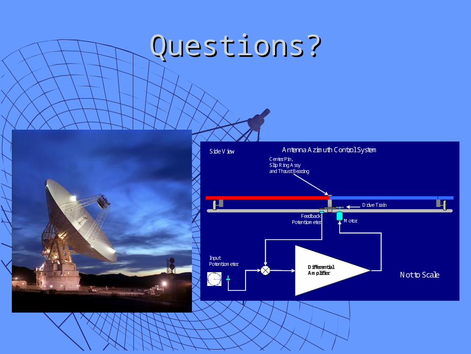
Questions?Questions?
Center Pin, Slip Ring Assy and Thrust Bearing
Feedback Potentiometer
Antenna Azimuth Control System Side View
Motor
Input Potentiometer
Differential Amplifier Not to Scale
Drive Train

BackupBackup

Block Diagram ReductionBlock Diagram Reduction
potK
potK
m g
m
KK K
s s a
os
eV s
iV s
is
Potentiometer
Potentiometer
potK
potK
K m
m
K
s s a
gK
Power Amp
Motor and Load
aE s
os
eV s
iV s
is
Potentiometer
Potentiometer
ms
Gears
potK
m g
m
KK K
s s a
os
is
pot m g
m
K KK K
s s a
os
is
sG
2
pot m g
m g m pot
KK K K
s a s KK K K
is
os
sT
1
G sT s
G s H s
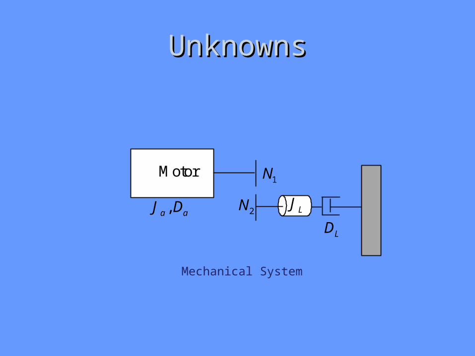
UnknownsUnknowns
Motor 1N
2N LJ
LD ,a aJ D
Mechanical System

1
t
m m a m
a m t bm
m a
Ks K R J
E s s s a K Ks s D
J R
2
1
2m a L
NJ J J
N
2
1
2m a L
ND D D
N
The value t
a
K
R is the motors torque constant divided by the motor armature resistance and
is equal to the rated stall torque of the motor divided by the motor armature input voltage
Stall
a
T
e.
Armature input voltage divided by the no-load speed of the motor results in the back
EMF constant of the motor or ab
no load
eK
.
The Mechanical System Problem

The Electrical System Problem
243.82
2volts
potrad
K
RFK
RG
This calculation makes two assumptions. First that saturation is never reached and second that the response of the amplifier is fast enough to neglect delay effects. If it is determined through experimentation that the response has been delayed the transfer
function for the amplifier will need to be modified to K
s a where
RFK
RG and
Rfa
RG .