Embed Size (px)
Citation preview

Ver.7
CLOSED LOOP STEPPING SYSTEMS
Model No.PB
1
CLOSED LOOP STEPPING SYSTEMS Model No.PB
Hybrid system combining the ease-of-use of stepping motors with the reliability of servomotors.
MERIT
1
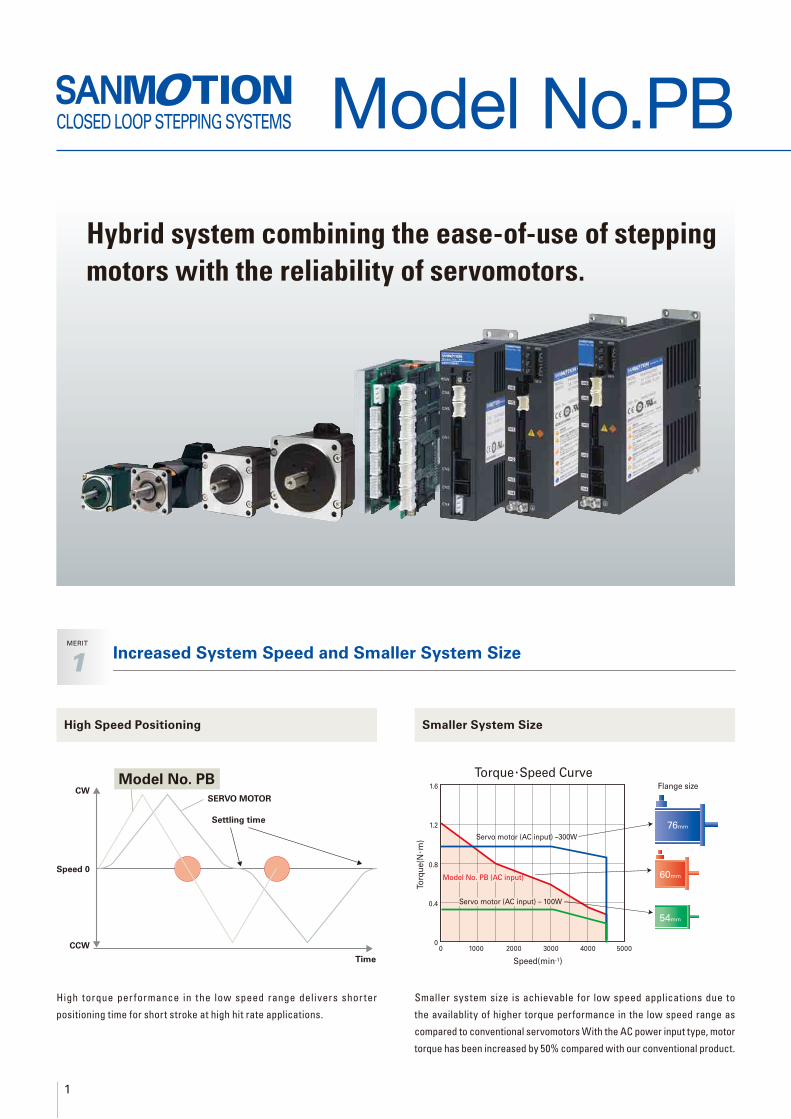
High Speed Positioning Smaller System Size
High torque per formance in the low speed range delivers shor ter
positioning time for short stroke at high hit rate applications.
Smaller system size is achievable for low speed applications due to
the availablity of higher torque performance in the low speed range as
compared to conventional servomotors With the AC power input type, motor
torque has been increased by 50% compared with our conventional product.
Time
Settling time
SERVO MOTOR
Model No. PBCW
Speed 0
CCW
Speed(min-1)
To
rqu
e(N
·m)
Flange size
0 1000 2000 3000 4000 50000
0.4
0.8
1.2
1.6
76mm
60mm
54mm
Torque ·Speed Curve
Servo motor (AC input) –300W
Model No. PB (AC input)
Servo motor (AC input) – 100W
Increased System Speed and Smaller System Size

2
Fe
atu
res a
nd
Fu
ncti
on
sT
yp
e R
Ty
pe P
Ty
pe M
Ha
rmo
nic
Ge
ar
Mo
de
lT
yp
e R
Mu
lti-
Ax
isE
lectr
om
ag
ne
tic
Bra
ke
Mo
de
lS
pu
r G
ea
r M
od
el
Sta
nd
ard
M
od
el
Mo
tor
Dim
en
sio
na
l D
raw
ing
s
Lo
w-b
ackla
sh
G
ear
Mo
del
Op
tio
ns
Stable Stand-StillMERIT
2
High Resolution
Improved Effi ciency from Current Control
MERIT
3
Able to set high resolutions. The AC model comes with electronic gear
and enables users to set any resolution, according to the device.
Higher ef ficiency from low heat generation is achieved by
controlling the current flow to motor according to motor load
With the AC power input type, motor heat generation has been
reduced for 60% compared with our conventional product.
0500 1000 1500 2000
Speed (min-1)
Tem
p in
cre
ase (
K)
20
60
80
Open controll
stepping system
Motor temperature rise
Model No.PB40
+1 pulse
-1 pulse
Target
position
Model No. PB system
Time
Motor
Speed 00
CW
CCW
Servo system
Stable Stand-Still
Complete stand-still motion is possible due to the availability of holding
torque, a typical characteristic of stepping motors. With the AC power
input t ype, a compensator function is buil t in to prevent posit ion
aberration from occurring due to load variation.
DC Multi-axis
ModelACmodelDCmodel
200
800
1600
3200
6400
12800
P/R
100
16000
P/R
500
1000
2000
4000
5000
10000
P/R
Electric Gire
AC Power Input DC Power Input
AC
Type
R General Purpose I/O Input Type (RS-485 + Parallel IO)
AC
Type
P Pulse-Train Input Type
DC
Type
M Multiple Input Type (General Purpose I/O Input + Pulse-Train Input)
DC
Type
R MultiAxis
General Purpose I/O Input Type (RS-485 + Parallel IO)
Energy-Saving

3
Reduced System Design Cost and TimeMERIT
5
Wide Availability of Optional Cables and Connectors
Cables and connectors for controller/amplifier and
amplifier/motor connection are available for hassle-
free setup.
CLOSED LOOP STEPPING SYSTEMS Model No.PB
Simplifi ed ControlMERIT
4
General Purpose I/O InputSupport For Various
Operations
AC
Type
RDC
Type
MDC
Type
R MultiAxis
AC
Type
RDC
Type
MDC
Type
R MultiAxis
System can be easily controlled by using the general purpose I/O to
designate preset point or program numbers. (AC Type R, DC Type M: 128
point DC Type R Multi-axis: 256 point)
Comprehensive built-in amplifier functionality includes thrust control,
point designation, programming, homing, holding brake control and
sensor limit input.
Point 1 output
Host device
Point 1
Point 0

4
Fe
atu
res a
nd
Fu
ncti
on
sT
yp
e R
Ty
pe P
Ty
pe M
Ha
rmo
nic
Ge
ar
Mo
de
lT
yp
e R
Mu
lti-
Ax
isE
lectr
om
ag
ne
tic
Bra
ke
Mo
de
lS
pu
r G
ea
r M
od
el
Sta
nd
ard
M
od
el
Mo
tor
Dim
en
sio
na
l D
raw
ing
s
Lo
w-b
ackla
sh
G
ear
Mo
del
Op
tio
ns
Complies with International Safety StandardsMERIT
6
PC Interface
Multi-Axis Type (DC Power Input)DC
Type
R MultiAxis
Built-in Pulse Generation
Function
AC
Type
RDC
Type
MDC
Type
R MultiAxis
A built-in pulse generation function is included in the Model No. PB
Types R and M. The amplifi er receives speed, acceleration/deceleration
and dis tance as numeric data f rom the upper- level device, and
automatically generates an optimal speed pat tern according to the
commands internally.Since no separate pulse generator is required, this
contributes to lower system cost.
Speed pattern
example
-4000
-3000
-2000
-1000
0
1000
2000
3000
4000
→Time
Ro
tati
on
s (
min
-1)
Parameter setting, data editing and monitoring of position and speed
can be done on a PC using the bundled setup software.
Multi-axis systems can be reduced in size and weight using
the PB-R 4-axis type.*1,2,3A can be selected using software switches.
PC Software
for WindowsPC
PB-R(4-axismodel)
Encoder
Cable
Motor
Cable
Motor (1A) Motor (2A) Motor (3A) Motor (3A)
*UL· CE compliant motors
have model numbers
ending with “-M”.
AC Power Input DC Power Input
AC
Type
R General Purpose I/O Input Type (RS-485 + Parallel IO)
AC
Type
P Pulse-Train Input Type
DC
Type
M Multiple Input Type (General Purpose I/O Input + Pulse-Train Input)
DC
Type
R MultiAxis
General Purpose I/O Input Type (RS-485 + Parallel IO)
Converter

5
Wide Variety of Amplifi ers Available
AC Power
Source
Type R
▶ P13
Type R
Multi-Axis
▶ P31
Type M
▶ P25
Type P
▶ P19
Network control with serial
communication
(RS-485 standard)
Point command control
with upper level device
such as PLC
Control with pulse generator
DC Power
Source
● Startup via I/O
Startup preset points or programs in the amplifi er memory using the I/O.
● Startup via Serial Communication
Control by transmitting speed, ac-celeration/deceleration and distance data via serial communication.
● Startup via I/O
Startup preset points or programs in the amplifi er memory using the I/O.
● Startup via Serial Communication
Control by transmitting speed, acceleration/deceleration and dis-tance data via serial communica-tion.
● Startup via I/O
Startup preset points or programs in the amplifi er memory using the I/O.
● Startup via Serial Communication
Control by transmitting speed, acceleration/deceleration and distance data via serial communication.
● With pulse control:
Motion is generated by responding to pulse input commands from a host device.
● With pulse
control:
Motion is generated by responding to pulse input commands from a host device.
Extensive Closed-Loop Stepping System Lineup
6
Fe
atu
res a
nd
Fu
ncti
on
sT
yp
e R
Ty
pe P
Ty
pe M
Ha
rmo
nic
Ge
ar
Mo
de
lT
yp
e R
Mu
lti-
Ax
isE
lectr
om
ag
ne
tic
Bra
ke
Mo
de
lS
pu
r G
ea
r M
od
el
Sta
nd
ard
M
od
el
Mo
tor
Dim
en
sio
na
l D
raw
ing
s
Lo
w-b
ackla
sh
G
ear
Mo
del
Op
tio
ns
AC Power Source
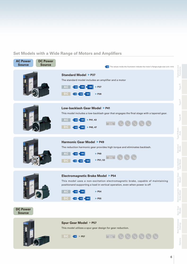
Set Models with a Wide Range of Motors and Amplifi ers
Standard Model ▶ P37
The standard model includes an amplifi er and a motor
Harmonic Gear Model ▶ P49
The reduction harmonic gear provides high torque and eliminates backlash.
Electromagnetic Brake Model ▶ P54
This model uses a non-excitation electromagnetic brake, capable of maintaining
positionand supporting a load in vertical operation, even when power is off
AC □42 □60 □ 86 ▶ P37
DC □28 □42
□60 ▶ P39
AC □42 □60 ▶ P49
DC □28 □42
□60 ▶ P51, 53
REDUCTIONGE ARR ATIO
130
150
1100
AC □42 □60 ▶ P54
DC □28 □42
□60 ▶ P55
AC □42 □60 ▶ P41, 43
DC □42 □60 ▶ P45, 47
REDUCTIONGE ARR ATIO
13.6
17.2
110
120
130
DC □28 ▶ P57
REDUCTIONGE ARR ATIO
13.6
17.2
110
120
130
150
Low-backlash Gear Model ▶ P41
This model includes a low-backlash gear that engages the fi nal stage with a tapered gear.
Spur Gear Model ▶ P57
This model utilizes a spur gear design for gear reduction.
DC Power Source
DC Power Source
□00 The values inside the illustration indicate the motor’s fl ange angle size (unit: mm)
7
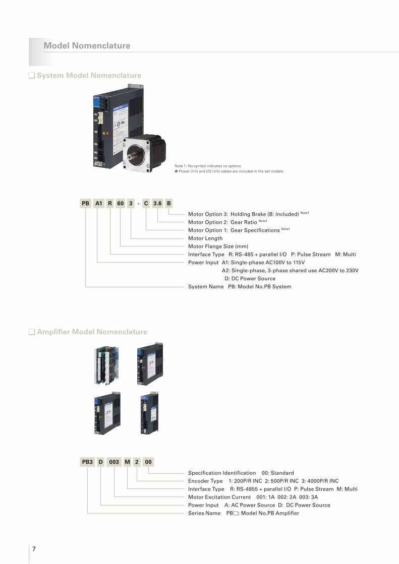
Model Nomenclature
System Model Nomenclature
Note 1: No symbol indicates no options.* Power (1m) and I/O (1m) cables are included in the set models.
Motor Option 3: Holding Brake (B: included) Note1
Motor Option 2: Gear Ratio Note1
Motor Option 1: Gear Specifi cations Note1
Motor Length
Motor Flange Size (mm)
Interface Type R: RS-485 + parallel I/O P: Pulse Stream M: Multi
Power Input A1: Single-phase AC100V to 115V
A2: Single-phase, 3-phase shared use AC200V to 230V
D: DC Power Source
System Name PB: Model No.PB System
Amplifier Model Nomenclature
Specifi cation Identifi cation 00: Standard
Encoder Type 1: 200P/R INC 2: 500P/R INC 3: 4000P/R INC
Interface Type R: RS-4855 + parallel I/O P: Pulse Stream M: Multi
Motor Excitation Current 001: 1A 002: 2A 003: 3A
Power Input A: AC Power Source D: DC Power Source
Series Name PB□: Model No.PB Amplifi er
PB A1 R 60 3 - C 3.6 B
PB3 D 003 M 2 00

8
Fe
atu
res a
nd
Fu
ncti
on
sT
yp
e R
Ty
pe P
Ty
pe M
Ha
rmo
nic
Ge
ar
Mo
de
lT
yp
e R
Mu
lti-
Ax
isE
lectr
om
ag
ne
tic
Bra
ke
Mo
de
lS
pu
r G
ea
r M
od
el
Sta
nd
ard
M
od
el
Mo
tor
Dim
en
sio
na
l D
raw
ing
s
Lo
w-b
ackla
sh
G
ear
Mo
del
Op
tio
ns
UL· CE
Specifi cation Identifi cation 30 or 20: Standard
Encoder Type K: 4000P/R with C-phase output
E: 500P/R with C-phase output
A: 200P/R No C-phase output DC (Multi-axis) only
C: 200P/R with C-phase output
Options *Contact us for assistance
X : without option
C : 24V DC Break
GA to GL : with Gear
HJ to HM : with Harmonic Gear
Power Input F: AC Power Source, DC Power Source (Single-axis)
D: DC Power Source (Multi-axis)
Motor Length
Motor Flange Size (mm)
Series Name PBM: Model No.PB Motor
Motor Model Nomenclature
*Please enquire separately for the sizes of PBM503 and PBM565.
PBM 60 3 F X K 30 - M
Cable Model Nomenclature
PBC 6 0010P A
Specifi cation Identifi cation
0000: Connector Set
0003: Cable Length 30cm
0010: Cable Length 1m
0030: Cable Length 3m
Cable Type P: Power supply M: Motor E: Encoder
S: I/O C: Communication
Control Number
Series Name PBC:PB Cable/Connector Set

9
List of Amplifi er/Motor Combinations and Optional Products
Motor Size
Amplifi er Model No.PB4A002R300PB4A002R301
PB4A002P300PB4A002P301
PB3D003M200PB3D003M201
PB2D003R1U0PB2D003R1U1PB2D003R1U2PB2D003R1U3
Interface Type RS-485 (Type R) Pulse-Train (Type P) RS-485 and Pulse-Train (Type M) RS-485(Type R)
Encoder Resolution 4000×4 Subdivisions=16000P/R 4000×4 Subdivisions=16000P/R 500×4 Subdivisions=2000P/R 200×4Subdivisions=800P/R
□28mm
StandardPBM282FXE20 PBM282DXA20
PBM284FXE20 PBM284DXA20
Spur Gear
1/3.6 PBM282FGAE20 PBM282DGAA20
1/7.2 PBM282FGBE20 PBM282DGBA20
1/10 PBM282FGEE20 PBM282DGEA20
1/20 PBM282FGGE20 PBM282DGGA20
1/30 PBM282FGJE20 PBM282DGJA20
1/50 PBM282FGLE20 PBM282DGLA20
Harmonic Gear1/50 PBM282FHLE20 PBM282DHLA20
1/100 PBM282FHME20 PBM282DHMA20
Electromagnetic BrakePBM282FCE20 PBM282DCA20
PBM284FCE20 PBM284DCA20
□42mm
Standard PBM423FXK30-M PBM423FXE20 PBM423DXA20
Low-backlash Gear
1/3.6 PBM423FGAK30-M PBM423FGAE20 PBM423DGAA20
1/7.2 PBM423FGBK30-M PBM423FGBE20 PBM423DGBA20
1/10 PBM423FGEK30-M PBM423FGEE20 PBM423DGEA20
1/20 PBM423FGGK30-M PBM423FGGE20 PBM423DGGA20
1/30 PBM423FGJK30-M PBM423FGJE20 PBM423DGJA20
Harmonic Gear
1/30 PBM423FHJK30-M PBM423FHJE20 PBM423DHJA20
1/50 PBM423FHLK30-M PBM423FHLE20 PBM423DHLA20
1/100 PBM423FHMK30-M PBM423FHME20 PBM423DHMA20
Electromagnetic Brake PBM423FCK30-M PBM423FCE20 PBM423DCA20
□60mm
StandardPBM603FXK30-M PBM603FXE20 PBM603DXA20
PBM604FXK30-M PBM604FXE20 PBM604DXA20
Low-backlash Gear
1/3.6 PBM603FGAK30-M PBM603FGAE20 PBM603DGAA20
1/7.2 PBM603FGBK30-M PBM603FGBE20 PBM603DGBA20
1/10 PBM603FGEK30-M PBM603FGEE20 PBM603DGEA20
1/20 PBM603FGGK30-M PBM603FGGE20 PBM603DGGA20
1/30 PBM603FGJK30-M PBM603FGJE20 PBM603DGJA20
Harmonic Gear1/50 PBM603FHLK30-M PBM603FHLE20 PBM603DHLA20
1/100 PBM603FHMK30-M PBM603FHME20 PBM603DHMA20
Electromagnetic BrakePBM603FCK30-M PBM603FCE20 PBM603DCA20
PBM604FCK30-M PBM604FCE20 PBM604DCA20
□86mm StandardPBM861FXK30-M
PBM862FXK30-M
Options
Power Cable PBC8P0010A PBC6P0010A
Motor Ext. Cable PBC7M0030A PBC6M0030A PBC4M0030A
Encoder Ext. Cable PBC7E0030A PBC6E0030APBC5E0030APBC5E0030C
I/O CablePBC5S0010A (un shielded)
PBC5S0010C (shield)PBC5S0010A (un shielded)
PBC5S0010C (shield)PBC4S0010A (un shielded)
Communication Cable Note 1) PBC6C0003A Not required PBC6C0003A PBC4C0003A
PC I/F Software SPBALL-01 SPBA1W-01 SPBD2W-01
USB / RS-485 Converter Unit PBFM-U6
Regenerative Unit PBFE-01
Note 1) Used when amplifi ers with several axes are connected via a daisy chain connection by telecommunication.
Motor Option Combination Table
Motor Option Combination Table
Motor No Gear Box Harmonic Gear Electromagnetic Brake
PBM282F□E20 / PBM282D□A20 ✓ ✓ ✓
PBM284F□E20 / PBM284D□A20 − − ✓
PBM423F□E20 / PBM423F□K30 / PBM423D□A20 ✓ ✓ ✓
PBM603F□E20 / PBM603F□K30 / PBM603D□A20 ✓ ✓ ✓
PBM604F□E20 / PBM604F□K30 / PBM604D□A20 − − ✓
Motor Standard Specifi cations (common to all models)
Motor No. PBM423F, PBM603F, PBM604F, PBM861F, PBM862F PBM282D, PBM282F, PBM284D, PBM284F, PBM423D, PBM603D, PBM604D
Insulation class Class B (130°C). UL compliant products are certifi ed with Class A (105°C).
Withstand Voltage * AC1500V 50/60Hz 1minute AC500V 50/60Hz 1minute
Insulation resistance * DC500V 100MΩMIN.
Degrees of protection IP40
Vibration resistance15G(Frequency range 10 to 70Hz amplitude 1.52mm 70 to 2000 acceleration 15G)
The x, y, and z are each tested 12 times with a sweep time of 15 minutes/cycle
Impact resistance 30G(half sine wave with 11 ms duration) The x, y and z are each tested three times for each direction for a total of 18 tests.
Ambient temperature −10°C to +40°C (Harmonic Gear Model 0°C to +40°C)
Ambient humidity 20 to 90%RH (No Condensation)
Elevation Maximum 1000m above sea level
* The user should not test the insulation resistance or insulation withstand voltage, because a capacitor has been inserted between the encoder output groundline and the frame to prevent noise.

10
Fe
atu
res a
nd
Fu
ncti
on
sT
yp
e R
Ty
pe P
Ty
pe M
Ha
rmo
nic
Ge
ar
Mo
de
lT
yp
e R
Mu
lti-
Ax
isE
lectr
om
ag
ne
tic
Bra
ke
Mo
de
lS
pu
r G
ea
r M
od
el
Sta
nd
ard
M
od
el
Mo
tor
Dim
en
sio
na
l D
raw
ing
s
Lo
w-b
ackla
sh
G
ear
Mo
del
Op
tio
ns
Set Model Confi gurations
AC Power Source Universal Input Type RS-485 + Parallel I/O (Type R)
ModelMotor Flange
Size
Reduction Gear Ratio
Power Source Set Model No.
Set Accessories
Amplifi er Model No. Motor Model No.Power Cable ·
I/O Cable
Standard Model
□42mm −Single-phase AC 100 to 115V PBA1R423 PB4A002R300 PBM423FXK30-M
Power Cable (1m): PBC8P0010A
I/O Cable (1m): PBC5S0010A
Single-phase/three-phase AC 200 to 230V PBA2R423 PB4A002R301 PBM423FXK30-M
□60mm −
Single-phase AC 100 to 115V PBA1R603 PB4A002R300 PBM603FXK30-M
Single-phase/three-phase AC 200 to 230V PBA2R603 PB4A002R301 PBM603FXK30-M
Single-phase AC 100 to 115V PBA1R604 PB4A002R300 PBM604FXK30-M
Single-phase/three-phase AC 200 to 230V PBA2R604 PB4A002R301 PBM604FXK30-M
□86mm −
Single-phase AC 100 to 115V PBA1R861 PB4A002R300 PBM861FXK30-M
Single-phase/three-phase AC 200 to 230V PBA2R861 PB4A002R301 PBM861FXK30-M
Single-phase AC 100 to 115V PBA1R862 PB4A002R300 PBM862FXK30-M
Single-phase/three-phase AC 200 to 230V PBA2R862 PB4A002R301 PBM862FXK30-M
Low-backlash Gear Model
□42mm
1/3.6Single-phase AC 100 to 115V PBA1R423-C3.6 PB4A002R300 PBM423FGAK30-M
Single-phase/three-phase AC 200 to 230V PBA2R423-C3.6 PB4A002R301 PBM423FGAK30-M
1/7.2Single-phase AC 100 to 115V PBA1R423-C7.2 PB4A002R300 PBM423FGBK30-M
Single-phase/three-phase AC 200 to 230V PBA2R423-C7.2 PB4A002R301 PBM423FGBK30-M
1/10Single-phase AC 100 to 115V PBA1R423-C10 PB4A002R300 PBM423FGEK30-M
Single-phase/three-phase AC 200 to 230V PBA2R423-C10 PB4A002R301 PBM423FGEK30-M
1/20Single-phase AC 100 to 115V PBA1R423-C20 PB4A002R300 PBM423FGGK30-M
Single-phase/three-phase AC 200 to 230V PBA2R423-C20 PB4A002R301 PBM423FGGK30-M
1/30Single-phase AC 100 to 115V PBA1R423-C30 PB4A002R300 PBM423FGJK30-M
Single-phase/three-phase AC 200 to 230V PBA2R423-C30 PB4A002R301 PBM423FGJK30-M
□60mm
1/3.6Single-phase AC 100 to 115V PBA1R603-C3.6 PB4A002R300 PBM603FGAK30-M
Single-phase/three-phase AC 200 to 230V PBA2R603-C3.6 PB4A002R301 PBM603FGAK30-M
1/7.2Single-phase AC 100 to 115V PBA1R603-C7.2 PB4A002R300 PBM603FGBK30-M
Single-phase/three-phase AC 200 to 230V PBA2R603-C7.2 PB4A002R301 PBM603FGBK30-M
1/10Single-phase AC 100 to 115V PBA1R603-C10 PB4A002R300 PBM603FGEK30-M
Single-phase/three-phase AC 200 to 230V PBA2R603-C10 PB4A002R301 PBM603FGEK30-M
1/20Single-phase AC 100 to 115V PBA1R603-C20 PB4A002R300 PBM603FGGK30-M
Single-phase/three-phase AC 200 to 230V PBA2R603-C20 PB4A002R301 PBM603FGGK30-M
1/30Single-phase AC 100 to 115V PBA1R603-C30 PB4A002R300 PBM603FGJK30-M
Single-phase/three-phase AC 200 to 230V PBA2R603-C30 PB4A002R301 PBM603FGJK30-M
Harmonic Gear Model
□42mm
1/30Single-phase AC 100 to 115V PBA1R423-H30 PB4A002R300 PBM423FHJK30-M
Single-phase/three-phase AC 200 to 230V PBA2R423-H30 PB4A002R301 PBM423FHJK30-M
1/50Single-phase AC 100 to 115V PBA1R423-H50 PB4A002R300 PBM423FHLK30-M
Single-phase/three-phase AC 200 to 230V PBA2R423-H50 PB4A002R301 PBM423FHLK30-M
1/100Single-phase AC 100 to 115V PBA1R423-H100 PB4A002R300 PBM423FHMK30-M
Single-phase/three-phase AC 200 to 230V PBA2R423-H100 PB4A002R301 PBM423FHMK30-M
□60mm
1/50Single-phase AC 100 to 115V PBA1R603-H50 PB4A002R300 PBM603FHLK30-M
Single-phase/three-phase AC 200 to 230V PBA2R603-H50 PB4A002R301 PBM603FHLK30-M
1/100Single-phase AC 100 to 115V PBA1R603-H100 PB4A002R300 PBM603FHMK30-M
Single-phase/three-phase AC 200 to 230V PBA2R603-H100 PB4A002R301 PBM603FHMK30-M
Electromag-netic Brake Model
□42mm −Single-phase AC 100 to 115V PBA1R423-B PB4A002R300 PBM423FCK30-M
Single-phase/three-phase AC 200 to 230V PBA2R423-B PB4A002R301 PBM423FCK30-M
□60mm −
Single-phase AC 100 to 115V PBA1R603-B PB4A002R300 PBM603FCK30-M
Single-phase/three-phase AC 200 to 230V PBA2R603-B PB4A002R301 PBM603FCK30-M
Single-phase AC 100 to 115V PBA1R604-B PB4A002R300 PBM604FCK30-M
Single-phase/three-phase AC 200 to 230V PBA2R604-B PB4A002R301 PBM604FCK30-M
Option Product Model Numbers (Not Included in Set Models)
Motor Ext. Cable PBC7M0030A
Encoder Ext. Cable PBC7E0030A
Communication Cable PBC6C0003A
PC I/F Software SPBALL-01
USB / RS-485 Converter Unit PBFM-U6

11
AC Power Source Pulse Train Input Type (Type P)
ModelMotor Flange
Size
Reduction Gear Ratio
Power Source Set Model No.
Set Accessories
Amplifi er Model No. Motor Model No.Power Cable ·
I/O Cable
Standard Model
□42mm −Single-phase AC 100 to 115V PBA1P423 PB4A002P300 PBM423FXK30-M
Power Cable (1m): PBC8P0010A
I/O Cable (1m): PBC5S0010C
Single-phase/three-phase AC 200 to 230V PBA2P423 PB4A002P301 PBM423FXK30-M
□60mm −
Single-phase AC 100 to 115V PBA1P603 PB4A002P300 PBM603FXK30-M
Single-phase/three-phase AC 200 to 230V PBA2P603 PB4A002P301 PBM603FXK30-M
Single-phase AC 100 to 115V PBA1P604 PB4A002P300 PBM604FXK30-M
Single-phase/three-phase AC 200 to 230V PBA2P604 PB4A002P301 PBM604FXK30-M
□86mm −
Single-phase AC 100 to 115V PBA1P861 PB4A002P300 PBM861FXK30-M
Single-phase/three-phase AC 200 to 230V PBA2P861 PB4A002P301 PBM861FXK30-M
Single-phase AC 100 to 115V PBA1P862 PB4A002P300 PBM862FXK30-M
Single-phase/three-phase AC 200 to 230V PBA2P862 PB4A002P301 PBM862FXK30-M
Low-backlash Gear Model
□42mm
1/3.6Single-phase AC 100 to 115V PBA1P423-C3.6 PB4A002P300 PBM423FGAK30-M
Single-phase/three-phase AC 200 to 230V PBA2P423-C3.6 PB4A002P301 PBM423FGAK30-M
1/7.2Single-phase AC 100 to 115V PBA1P423-C7.2 PB4A002P300 PBM423FGBK30-M
Single-phase/three-phase AC 200 to 230V PBA2P423-C7.2 PB4A002P301 PBM423FGBK30-M
1/10Single-phase AC 100 to 115V PBA1P423-C10 PB4A002P300 PBM423FGEK30-M
Single-phase/three-phase AC 200 to 230V PBA2P423-C10 PB4A002P301 PBM423FGEK30-M
1/20Single-phase AC 100 to 115V PBA1P423-C20 PB4A002P300 PBM423FGGK30-M
Single-phase/three-phase AC 200 to 230V PBA2P423-C20 PB4A002P301 PBM423FGGK30-M
1/30Single-phase AC 100 to 115V PBA1P423-C30 PB4A002P300 PBM423FGJK30-M
Single-phase/three-phase AC 200 to 230V PBA2P423-C30 PB4A002P301 PBM423FGJK30-M
□60mm
1/3.6Single-phase AC 100 to 115V PBA1P603-C3.6 PB4A002P300 PBM603FGAK30-M
Single-phase/three-phase AC 200 to 230V PBA2P603-C3.6 PB4A002P301 PBM603FGAK30-M
1/7.2Single-phase AC 100 to 115V PBA1P603-C7.2 PB4A002P300 PBM603FGBK30-M
Single-phase/three-phase AC 200 to 230V PBA2P603-C7.2 PB4A002P301 PBM603FGBK30-M
1/10Single-phase AC 100 to 115V PBA1P603-C10 PB4A002P300 PBM603FGEK30-M
Single-phase/three-phase AC 200 to 230V PBA2P603-C10 PB4A002P301 PBM603FGEK30-M
1/20Single-phase AC 100 to 115V PBA1P603-C20 PB4A002P300 PBM603FGGK30-M
Single-phase/three-phase AC 200 to 230V PBA2P603-C20 PB4A002P301 PBM603FGGK30-M
1/30Single-phase AC 100 to 115V PBA1P603-C30 PB4A002P300 PBM603FGJK30-M
Single-phase/three-phase AC 200 to 230V PBA2P603-C30 PB4A002P301 PBM603FGJK30-M
Harmonic Gear Model
□42mm
1/30Single-phase AC 100 to 115V PBA1P423-H30 PB4A002P300 PBM423FHJK30-M
Single-phase/three-phase AC 200 to 230V PBA2P423-H30 PB4A002P301 PBM423FHJK30-M
1/50Single-phase AC 100 to 115V PBA1P423-H50 PB4A002P300 PBM423FHLK30-M
Single-phase/three-phase AC 200 to 230V PBA2P423-H50 PB4A002P301 PBM423FHLK30-M
1/100Single-phase AC 100 to 115V PBA1P423-H100 PB4A002P300 PBM423FHMK30-M
Single-phase/three-phase AC 200 to 230V PBA2P423-H100 PB4A002P301 PBM423FHMK30-M
□60mm
1/50Single-phase AC 100 to 115V PBA1P603-H50 PB4A002P300 PBM603FHLK30-M
Single-phase/three-phase AC 200 to 230V PBA2P603-H50 PB4A002P301 PBM603FHLK30-M
1/100Single-phase AC 100 to 115V PBA1P603-H100 PB4A002P300 PBM603FHMK30-M
Single-phase/three-phase AC 200 to 230V PBA2P603-H100 PB4A002P301 PBM603FHMK30-M
Electromag-netic Brake Model
□42mm −Single-phase AC 100 to 115V PBA1P423-B PB4A002P300 PBM423FCK30-M
Single-phase/three-phase AC 200 to 230V PBA2P423-B PB4A002P301 PBM423FCK30-M
□60mm −
Single-phase AC 100 to 115V PBA1P603-B PB4A002P300 PBM603FCK30-M
Single-phase/three-phase AC 200 to 230V PBA2P603-B PB4A002P301 PBM603FCK30-M
Single-phase AC 100 to 115V PBA1P604-B PB4A002P300 PBM604FCK30-M
Single-phase/three-phase AC 200 to 230V PBA2P604-B PB4A002P301 PBM604FCK30-M
Option Product Model Numbers (Not Included in Set Models)
Motor Ext. Cable PBC7M0030A
Encoder Ext. Cable PBC7E0030A
PC I/F Software SPBALL-01
USB / RS-485 Converter Unit PBFM-U6

12
Fe
atu
res a
nd
Fu
ncti
on
sT
yp
e R
Ty
pe P
Ty
pe M
Ha
rmo
nic
Ge
ar
Mo
de
lT
yp
e R
Mu
lti-
Ax
isE
lectr
om
ag
ne
tic
Bra
ke
Mo
de
lS
pu
r G
ea
r M
od
el
Sta
nd
ard
M
od
el
Mo
tor
Dim
en
sio
na
l D
raw
ing
s
Lo
w-b
ackla
sh
G
ear
Mo
del
Op
tio
ns
DC Power Source Multi Input Type (Universal Input + Pulse Train Input) (Type M)
ModelMotor
Flange SizeReduction Gear Ratio
Set Model No.
Set Accessories
Amplifi er Model No. Motor Model No.Power Cable ·
I/O Cable
Standard Model
□28mm −PBDM282 PB3D003M200 PBM282FXE20
Power Cable (1m): PBC6P0010A
I/O Cable (1m): PBC5S0010C
PBDM284 PB3D003M200 PBM284FXE20
□42mm − PBDM423 PB3D003M200 PBM423FXE20
□60mm −PBDM603 PB3D003M200 PBM603FXE20
PBDM604 PB3D003M200 PBM604FXE20
Low-backlash Gear Model
□42mm
1/3.6 PBDM423-C3.6 PB3D003M200 PBM423FGAE20
1/7.2 PBDM423-C7.2 PB3D003M200 PBM423FGBE20
1/10 PBDM423-C10 PB3D003M200 PBM423FGEE20
1/20 PBDM423-C20 PB3D003M200 PBM423FGGE20
1/30 PBDM423-C30 PB3D003M200 PBM423FGJE20
□60mm
1/3.6 PBDM603-C3.6 PB3D003M200 PBM603FGAE20
1/7.2 PBDM603-C7.2 PB3D003M200 PBM603FGBE20
1/10 PBDM603-C10 PB3D003M200 PBM603FGEE20
1/20 PBDM603-C20 PB3D003M200 PBM603FGGE20
1/30 PBDM603-C30 PB3D003M200 PBM603FGJE20
Spur Gear Model □28mm
1/3.6 PBDM282-G3.6 PB3D003M200 PBM282FGAE20
1/7.2 PBDM282-G7.2 PB3D003M200 PBM282FGBE20
1/10 PBDM282-G10 PB3D003M200 PBM282FGEE20
1/20 PBDM282-G20 PB3D003M200 PBM282FGGE20
1/30 PBDM282-G30 PB3D003M200 PBM282FGJE20
1/50 PBDM282-G50 PB3D003M200 PBM282FGLE20
Harmonic Gear Model
□28mm1/50 PBDM282-H50 PB3D003M200 PBM282FHLE20
1/100 PBDM282-H100 PB3D003M200 PBM282FHME20
□42mm
1/30 PBDM423-H30 PB3D003M200 PBM423FHJE20
1/50 PBDM423-H50 PB3D003M200 PBM423FHLE20
1/100 PBDM423-H100 PB3D003M200 PBM423FHME20
□60mm1/50 PBDM603-H50 PB3D003M200 PBM603FHLE20
1/100 PBDM603-H100 PB3D003M200 PBM603FHME20
Electromagnetic Brake Model
□28mm −PBDM282-B PB3D003M200 PBM282FCE20
PBDM284-B PB3D003M200 PBM284FCE20
□42mm − PBDM423-B PB3D003M200 PBM423FCE20
□60mm −PBDM603-B PB3D003M200 PBM603FCE20
PBDM604-B PB3D003M200 PBM604FCE20
Option Product Model Numbers (Not Included in Set Models)
Motor Ext. Cable PBC6M0030A
Encoder Ext. Cable PBC6E0030A
Communication Cable PBC6C0003A
PC I/F Software SPBA1W-01
USB / RS-485 Converter Unit PBFM-U6

13
Circuit Breaker
Electromagnetic Contactor
Noise Filter
Protects the power line; shuts off circuit during an overfl ow of electric current.
Switches amplifi er power on and off. Installation of a surge protector is required.
Protects the power line from external noise, and from noise generated by the amplifi er
Controller PC
⑦ PCIF Software
Serial communication control
parameter editing
⑥ Communication Converter Unit
* A converter unit is required for USB/RS-485 conversion.
To other slaves
① Power Cable
Standard: PBC8P0010A
Connector Set: PBC8P0000A
③ Encoder Ext. Cable
Standard: PBC7E0030A
Connector Set: PBC7E0000A
② Motor Ext. Cable
Standard: PBC7M0030A
Connector Set: PBC7M0000A
④ I/O Cable
Standard: PBC5S0010A
Connector Set: PBC5S0000A
CN3
CN2
CN1
CN5
CN6
⑤ Communication Cable
Standard: PBC6C0003A
Connector Set: PBC6C0000A
CN4
RS-485 (Half Duplex)
Single-phase AC100V
or Single-phase / 3-phase AC200V
Host Devices
PLC
Model No. PB Type R Single-Axis Type
AC Power Input Type
System Confi guration

14
Fe
atu
res a
nd
Fu
ncti
on
sT
yp
e R
Ty
pe P
Ty
pe M
Ha
rmo
nic
Ge
ar
Mo
de
lT
yp
e R
Mu
lti-
Ax
isE
lectr
om
ag
ne
tic
Bra
ke
Mo
de
lS
pu
r G
ea
r M
od
el
Sta
nd
ard
M
od
el
Mo
tor
Dim
en
sio
na
l D
raw
ing
s
Lo
w-b
ackla
sh
G
ear
Mo
del
Op
tio
ns
Options
Cable TypeStandard Model Number (Length)
Connector Set Model Number
Maximum Length Remarks
① Power Cable PBC8P0010A (1m) PBC8P0000A 3m −
② Motor Ext. Cable PBC7M0030A (3m) PBC7M0000A 20m Use when an extension of 50cm or more is required.
③ Encoder Ext. Cable PBC7E0030A (3m) PBC7E0000A 20m Use when an extension of 50cm or more is required.
④ I/O Cable (unshielded) PBC5S0010A (1m) PBC5S0000A 2m Please select depending on the noise environment.
④ I/O Cable (shielded) PBC5S0010C (1m) PBC5S0000A 2m Please select depending on the noise environment.
⑤ Communication Cable (to Amp.) PBC6C0003A (30cm) PBC6C0000A 100mUse when multiple axes are connected in a daisy-chain confi guration for communication.
⑥ Communication Converter Unit PBFM-U6 −USB/RS-485 Converter UnitConverter unit and cable set model
⑦ PC I/F Software SPBALL-01 − − Software for operational check and parameter setting

15
Optional Cable
③ Encoder Ext. Cable
MOTOR SIDE CONNECTOR
HOUSING: 1-1903130-6
TERMINAL: 1903111-2
MANUFACTURER: AMP
AMPLIFIER SIDE CONNECTOR
HOUSING: 1-1827864-6
TERMINAL: 1827569-2
MANUFACTURER: AMP
LEAD WIRE AWG28 ENCODER CABLE
UL20276
3000±50
Connector Connection Of Motor Side
PIN No. LEAD COLR Signal Name
A1 Blue CHANNEL A
B1 Brown CHANNEL A
A2 Green CHANNEL B
B2 Purple CHANNEL B
A3 White CHANNEL C
B3 Yellow CHANNEL C
A4 Red +5V
B4 Black 0V
A5 N.C. −
B5 Orange OVER HEAT
A6 Black Shield
B6 N.C. −
Connector Connection Of Amplifi er Side
PIN No. LEAD COLR Signal Name
A1 Blue CHANNEL A
B1 Brown CHANNEL A
A2 Green CHANNEL B
B2 Purple CHANNEL B
A3 White CHANNEL C
B3 Yellow CHANNEL C
A4 Red +5V
B4 Black 0V
A5 N.C. −
B5 Orange OVER HEAT
A6 Black Shield
B6 N.C. −
Connector Set:PBC7E0000A
Manufacturer Type Qty.
AMP
Housing: 1-1903130-6 1
Terminal: 1903112-2 10
Housing: 1-1827864-6 1
Terminal: 1827570-2 10
① Power Cable
Connector Connection
PIN No. LEAD COLR Signal Name
A1 − −
B1 Black R
A2 − −
B2 Black S
A3 − −
B3 Black T
Connector Set:PBC8P0000A
Manufacturer Type Qty.
AMPHousing: 1-1318119-3 1
Contact: 1318107-1 6
② Motor Ext. Cable
Connector Connection Of Motor Side
PIN No. LEAD COLR Signal Name
A1 Blue Motor Lead Wire
B1 Orange Motor Lead Wire
A2 Red Motor Lead Wire
B2 Yellow Motor Lead Wire
A3 White Brake Lead Wire
B3 Black Brake Lead Wire
Connector Connection Of Amplifi er Side
PIN No. LEAD COLR Signal Name
1(A1) Blue Motor Lead Wire
2(B1) Orange Motor Lead Wire
3(A2) Red Motor Lead Wire
4(B2) Yellow Motor Lead Wire
5(A3) White Brake Lead Wire
6(B3) Black Brake Lead Wire
Connector Set:PBC7M0000A
Manufacturer Type Qty.
AMP
Housing: 1-1903130-3 1
Terminal: 1903112-2 6
Housing: 1-1827864-3 1
Terminal: 1827570-2 6
MOTOR SIDE CONNECTOR
HOUSING: 1-1903130-3
TERMINAL: 1903112-2
MANUFACTURER: AMP
AMPLIFIER SIDE CONNECTOR
HOUSING: 1-1827864-3
TERMINAL: 1827570-2
MANUFACTURER: AMP
LEAD WIRE AWG22
3000±50
MOTOR CABLE
UL2517
Power Supply
1 (A1)
Amp.side
1000±505 (A3) 6 (B3)
2 (B1)UL1430 AWG18
Model No. PB Type R Single-Axis Type
AC Power Input Type

16
Fe
atu
res a
nd
Fu
ncti
on
sT
yp
e R
Ty
pe P
Ty
pe M
Ha
rmo
nic
Ge
ar
Mo
de
lT
yp
e R
Mu
lti-
Ax
isE
lectr
om
ag
ne
tic
Bra
ke
Mo
de
lS
pu
r G
ea
r M
od
el
Sta
nd
ard
M
od
el
Mo
tor
Dim
en
sio
na
l D
raw
ing
s
Lo
w-b
ackla
sh
G
ear
Mo
del
Op
tio
ns
Optional Cable
⑤ Communication Cable
Connector Set:PBC6C0000A
Manufacturer Type Qty.
JSTHousing: PADP-10V-1-S 1
Contact: SPH-002T-P0.5L 10
Connector relay cable
10
2
9
1 L±30
1
9
④ I/O Cable (unshielded)
④ I/O Cable (shielded)
A1▷
L
A13
B1
B13
Flat cable UL2962 AWG28
Cable Mark
1mm MAX.
Cable 1
Cable 2
Cable Connection
Cable 1 Cable 2
A1-No.1 B1-No.14
A2-No.2 B2-No.15
A3-No.3 B3-No.16
A4-No.4 B4-No.17
A5-No.5 B5-No.18
A6-No.6 B6-No.19
A7-No.7 B7-No.20
A8-No.8 B8-No.21
A9-No.9 B9-No.22
A10-No.10 B10-No.23
A11-No.11 B11-No.24
A12-No.12 B12-No.25
A13-No.13 B13-No.26
Connector Set:PBC5S0000A
Manufacturer Type Qty.
KEL Housing: 8822E-026-171D-F 1
A1▷
L±50
A13
B1
B13
15
0±10
CN Wiring
CN1 Pin.No. Mark Display Mark LINE COLR
A1
|
RedOrange
A2 Black
A3 RedGray
A4 Black
A5 RedWhite
A6 Black
A7 RedYellow
A8 Black
A9 RedPink
A10 Black
A11|
|
RedOrange
A12 Black
A13 Red Gray
CN1 Pin.No. Mark Display Mark LINE COLR
B1 Black Gray
B2
|
|
RedWhite
B3 Black
B4 RedYellow
B5 Black
B6 RedPink
B7 Black
B8
|
|
|
RedOrange
B9 Black
B10 RedGray
B11 Black
B12 RedWhite
B13 Black
Connector Set:PBC5S0000A
Manufacturer Type Qty.
KEL Housing: 8822E-026-171D-F 1
Yellow
White
Brown
Blue
Black
Purple
Green
Drain
Yellow
White
Brown
Blue
Black
Purple
Green
Drain
A
B
(Y)(Z)GND
Vcc
PCA
PCB
24V
GND
A
B
(Y)(Z)GND
Vcc
PCA
PCB
24V
GND
1
2
3
4
5
6
7
8
9
10
1
2
3
4
5
6
7
8
9
10
CNA
Pin.No.
CNB
Pin.No.Signal
Name
Signal
Name

17
Amplifi er Model PB4A002R300 PB4A002R301
Power Supply Single phase AC100V to 115V −15% +10% 50/60Hz Single phase / 3-phase AC200V to 230V −15% +10% 50/60Hz
Control Mode PWM Control SIN drive method
Environ-ment
Ambient temp.
Operating 0 to 55°C
Storage −20 to 65°C
Operating/Storage Humidity
90%RH (non-condensing)
Vibration Resistance 0.5G (tested with frequency range 10 to 55 Hz, X, Y, Z each direction 2H)
Structure Tray structure Rear mounting type
Mass Approx. 0.65kg
Dimensions W42×H150×D120
Functions
Rotation Speed 0 to 4500min-1 (□86mm: 0 to 4000min-1)
Resolution (P/R) Electronic gear 100 to 16000
Regeneration Process Internal (Software processing)
Holding brake control function
Internal
Protective FunctionsPower Voltage Error, Regeneration Voltage Error, Over-speed, Encoder Disconnection, CPU Error, Overload stop, Servo Error, Zero-return Error, Nonvolatile Memory Error, Initialization Error, Over-current, Amplifi er Overheat, Motor Overheat, Counter Overfl ow
Display 7SEG LED Display (2 pieces)
Digital operatorResolution, Related motor, Positive direction defi nition, Gain, Node Adress, Trans. Speed, Holding brake control, Jog driving
Operation Functions Auto Zero-return / Push Operation (Current limit)
Communication specifi cations (PCIF)
RS-485 Start-Stop Synchronization, Half Duplex Communication, Trans. Speed: 9600, 38400, 115200, 307200bps
Input/Output Signals
Input Signals
FunctionsALMCLRGeneral-purpose input ×8 (Point, STOP, EXE, SELECT, HOME sensor, Limit, Deviation CLR, Pause, Jog, Inter lock)
Electric General-purpose input: Interactive input photo coupler DC5V to 24V
Output Signals
FunctionsALMCLRGeneral-purpose output×7 (Point No, Ack, Busy, HOME END, Push END, ZONE, Input Monitor, In-Position, Bit Out)
Electric General-purpose output: Open collector, DC30V/15mA max
General Specifi cations
Amplifi er Dimensional Drawing (Unit:mm)
Model No. PB Type R Single-Axis Type
AC Power Input Type
MADE IN JAPAN00******
Model No.PBCLOSED LOOP STEPPING SYSTEMS
∅5
33 4.5
42
516
0(5
)
(10)
15
010
17
0
5
4 3 210F
E
DCBA
98765
CN4
CN3
CN2
CN1
CN5
CN6
DATA
MODESW
4.5
120
Fear of a burn! Do not touch a heat sink.
Equipment may be damaged if mistaken connection is made.
on or within 10MIN after power off.
maintenance and check.Be sure that the charge lamp is off at the time of
Electric shock cautions.
Do not touch drive unit or terminal cover during power
Connect earth terminal against electric shock.
Direction of Installation
Up

18
Fe
atu
res a
nd
Fu
ncti
on
sT
yp
e R
Ty
pe P
Ty
pe M
Ha
rmo
nic
Ge
ar
Mo
de
lT
yp
e R
Mu
lti-
Ax
isE
lectr
om
ag
ne
tic
Bra
ke
Mo
de
lS
pu
r G
ea
r M
od
el
Sta
nd
ard
M
od
el
Mo
tor
Dim
en
sio
na
l D
raw
ing
s
Lo
w-b
ackla
sh
G
ear
Mo
del
Op
tio
ns
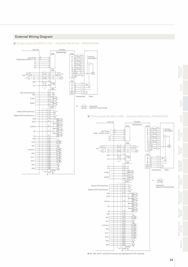
External Wiring Diagram
Amplifier
PB4A002R301
P.E(M4)
(PEND1) OUT4 20
(PEND4) OUT7
(PEND3) OUT6
(PEND2) OUT523
262524
2221
(Busy) OUT3
(In-Posi) OUT2
(ACK) OUT1
17
1918
161514
9
(STOP) IN8
ALM
(-H.Limit) IN7
131211
10
(+H.Limit) IN6
(Point4) IN5
8
7
4
COM 1
4
(Point2) IN3
(Point3) IN4
(Point1) IN2
6
5
(EXE) IN1
ALMCLR
3
2
9DC24VGND
CN1
10 GND24V
N.C
GND
+5V78
6
5GND
CN4
3N.C
123
CN5,6
2φ/3φ AC200V to 230V Input Power 4
16
2
User unit
*)
Twisted PairCable With External Shield
5B
Holding brake
BRK- 6BRK+
Motor
A
B 34
2A
CN31
CN2
C 6
N.C
FG 1112N.C
10O.H
5G 89
75V
TH
B 3
5C
4B
A2A
1 OPTICALENCORDER
N.C
N.CN.C N.C
N.CHost Controler
PCIF
R
TS
5N.C
* In the case of AC200V input.* The I/O signal name in ( ) shows an initial value.
Three-phase AC 200 to 230V Amplifi er Model No.: PB4A002R301 ■
Single-phase AC100V to 115V Amplifi er Model No.: PB4A002R300 ■
PB4A002R300
P.E(M4)
OUT4 20
OUT7
OUT6
OUT523
262524
2221
OUT3
OUT2
OUT1
17
1918
161514
9
IN8
ALM
IN7
131211
10
IN6
IN5
8
7
4
COM 1
4
IN3
IN4
IN2
6
5
IN1
ALMCLR
3
2
9DC24VGND
CN1
10 GND24V
N.C
GND
+5V78
6
5GND
CN4
3N.C
123
CN5,6
2φAC100V to 115V Input Power
4
16
2
User unit
*)
5B
Holding brake/(24V)
BRK- 6BRK+
Motor
A
B 34
2A
CN31
CN2
C 6
N.C
FG 1112N.C
10O.H
5G 89
75V
TH
B 3
5C
4B
A2A
1
N.C
N.CN.C N.C
N.CHost Controler
PCIF
(CMD9 enabled)
COM1
COM2
(115200bps fixed)
N.C
*1 Backup power supply
Amplifier
Twisted PairCable With External Shield
OPTICALENCORDER

19
Circuit Breaker
Electromagnetic Contactor
Noise Filter
Protects the power line; shuts off circuit during an overfl ow of electric current.
Switches amplifi er power on and off. Installation of a surge protector is required.
Protects the power line from external noise, and from noise generated by the amplifi er.
CN2
CN4
Parameter editing
① Power Cable
Standard: PBC8P0010A
Connector Set: PBC8P0000A② Motor Ext. Cable
Standard: PBC7M0030A
Connector Set: PBC7M0000A
③ Encoder Ext. Cable
Standard: PBC7E0030A
Connector Set: PBC7E0000A
④ I/O Cable
Standard: PBC5S0010C
Connector Set: PBC5S0000A
PC
③ Encoder Ext. Cable
Standard: PBC7E0030A
Connector Set: PBC7E0000A
② Motor Ext. Cable
Standard: PBC7M0030A
Connector Set: PBC7M0000A
CN3
CN2
CN1
To external limit sensor
CN6
CN5
RS-485 (Half Duplex)
⑤ Limit input Cable
Standard: PBC7S0010A
Connector Set: PBC7S0000A
Single-phase AC100V
or Single-phase / 3-phase AC200V
Model No. PB Type P
AC Power Input Type
⑥ Communication Converter Unit
* A converter unit is required for USB/RS-485 conversion.PC
⑦ PC I/F Software
PLC/Pulse board
Control Device
Controller
System Confi guration

20
Fe
atu
res a
nd
Fu
ncti
on
sT
yp
e R
Ty
pe P
Ty
pe M
Ha
rmo
nic
Ge
ar
Mo
de
lT
yp
e R
Mu
lti-
Ax
isE
lectr
om
ag
ne
tic
Bra
ke
Mo
de
lS
pu
r G
ea
r M
od
el
Sta
nd
ard
M
od
el
Mo
tor
Dim
en
sio
na
l D
raw
ing
s
Lo
w-b
ackla
sh
G
ear
Mo
del
Op
tio
ns
Options
Cable TypeStandard Model Number (Length)
Connector Set Model Number
Maximum Length Remarks
① Power Cable PBC8P0010A (1m) PBC8P0000A 3m −
② Motor Ext. Cable PBC7M0030A (3m) PBC7M0000A 20m Use when an extension of 50cm or more is required.
③ Encoder Ext. Cable PBC7E0030A (3m) PBC7E0000A 20m Use when an extension of 50cm or more is required.
④ I/O Cable (shielded) PBC5S0010C (1m) PBC5S0000A 2m −
⑤ Limit Input Cable PBC7S0010A (1m) PBC7S0000A 2m External limit sensor input
⑥ Communication Converter Unit PBFM-U6 −USB/RS-485 Converter UnitConverter unit and cable set model
⑦ PC I/F Software SPBALL-01 − − Software for operational check and parameter setting

21
Optional Cable
③ Encoder Ext. Cable
① Power Cable
② Motor Ext. Cable
Connector Connection Of Motor Side
PIN No. LEAD COLR Signal Name
A1 Blue Motor Lead Wire
B1 Orange Motor Lead Wire
A2 Red Motor Lead Wire
B2 Yellow Motor Lead Wire
A3 White Brake Lead Wire
B3 Black Brake Lead Wire
Connector Connection Of Amplifi er Side
PIN No. LEAD COLR Signal Name
1(A1) Blue Motor Lead Wire
2(B1) Orange Motor Lead Wire
3(A2) Red Motor Lead Wire
4(B2) Yellow Motor Lead Wire
5(A3) White Brake Lead Wire
6(B3) Black Brake Lead Wire
Connector Set:PBC7M0000A
Manufacturer Type Qty.
AMP
Housing: 1-1903130-3 1
Terminal: 1903112-2 6
Housing: 1-1827864-3 1
Terminal: 1827570-2 6
MOTOR SIDE CONNECTOR
HOUSING: 1-1903130-3
TERMINAL: 1903112-2
MANUFACTURER: AMP
AMPLIFIER SIDE CONNECTOR
HOUSING: 1-1827864-3
TERMINAL: 1827570-2
MANUFACTURER: AMP
LEAD WIRE AWG22
3000±50
MOTOR CABLE
UL2517
MOTOR SIDE CONNECTOR
HOUSING: 1-1903130-6
TERMINAL: 1903111-2
MANUFACTURER: AMP
AMPLIFIER SIDE CONNECTOR
HOUSING: 1-1827864-6
TERMINAL: 1827569-2
MANUFACTURER: AMP
LEAD WIRE AWG28 ENCODER CABLE
UL20276
3000±50
Connector Connection Of Motor Side
PIN No. LEAD COLR Signal Name
A1 Blue CHANNEL A
B1 Brown CHANNEL A
A2 Green CHANNEL B
B2 Purple CHANNEL B
A3 White CHANNEL C
B3 Yellow CHANNEL C
A4 Red +5V
B4 Black 0V
A5 N.C. −
B5 Orange OVER HEAT
A6 Black Shield
B6 N.C. −
Connector Connection Of Amplifi er Side
PIN No. LEAD COLR Signal Name
A1 Blue CHANNEL A
B1 Brown CHANNEL A
A2 Green CHANNEL B
B2 Purple CHANNEL B
A3 White CHANNEL C
B3 Yellow CHANNEL C
A4 Red +5V
B4 Black 0V
A5 N.C. −
B5 Orange OVER HEAT
A6 Black Shield
B6 N.C. −
Connector Set:PBC7E0000A
Manufacturer Type Qty.
AMP
Housing: 1-1827864-6 1
Terminal: 1903112-2 10
Housing: 1-1903130-6 1
Terminal: 1827570-2 10
Connector Connection
PIN No. LEAD COLR Signal Name
A1 − −
B1 Black R
A2 − −
B2 Black S
A3 − −
B3 Black T
Connector Set:PBC8P0000A
Manufacturer Type Qty.
AMPHousing: 1-1318119-3 1
Contact: 1318107-1 6
Amp.side
1000±50
Power Supply
5 (A3)
1 (A1)
6 (B3)
2 (B1) UL1430 AWG18
Model No. PB Type P
AC Power Input Type

22
Fe
atu
res a
nd
Fu
ncti
on
sT
yp
e R
Ty
pe P
Ty
pe M
Ha
rmo
nic
Ge
ar
Mo
de
lT
yp
e R
Mu
lti-
Ax
isE
lectr
om
ag
ne
tic
Bra
ke
Mo
de
lS
pu
r G
ea
r M
od
el
Sta
nd
ard
M
od
el
Mo
tor
Dim
en
sio
na
l D
raw
ing
s
Lo
w-b
ackla
sh
G
ear
Mo
del
Op
tio
ns
Optional Cable
④ I/O Cable (shielded)
⑤ Limit Input Cable
A1▷
L±50
A13
B1
B13
15
0±10
CN Wiring
CN1 Pin.No. Mark Display Mark LINE COLR
A1
|
RedOrange
A2 Black
A3 RedGray
A4 Black
A5 RedWhite
A6 Black
A7 RedYellow
A8 Black
A9 RedPink
A10 Black
A11|
|
RedOrange
A12 Black
A13 Red Gray
CN1 Pin.No. Mark Display Mark LINE COLR
B1 Black Gray
B2
|
|
RedWhite
B3 Black
B4 RedYellow
B5 Black
B6 RedPink
B7 Black
B8
|
|
|
RedOrange
B9 Black
B10 RedGray
B11 Black
B12 RedWhite
B13 Black
Connector Set:PBC5S0000A
Manufacturer Type Qty.
KEL Housing: 8822E-026-171D-F 1
Connector Set: PBC7S0000A
Manufacturer Type Qty.
Hirose
Electric
Housing: DF11-10DS-2C 1
Contact: DF11-2428SCA 10
10 9
2 11000±30
Housing DF11-10DS-2C (Hirose Electric)
Contact DF11-22SCA (Hirose Electric)
AWG22Stranded wire UL3266
Connector Connection Of Amplifi er Side
PIN No. LEAD COLR Signal Name
1 Red −
2 Blue −
3 Black Positive Limit +
4 Black Positive Limit +
5 Black Negative Limit −
6 Black Negative Limit −
7 N.C. −
8 N.C. −
9 N.C. −
10 N.C. −

23
General Specifi cations
Amplifi er Dimensional Drawing (Unit:mm)
Amplifi er Model PB4A002P300 PB4A002P301
Power Supply Single phase AC100V to 115V −15% +10% 50/60Hz Single phase / 3-phase AC200V to 230V −15% +10% 50/60Hz
Control Mode PWM Control SIN drive method
Environment
Ambient temp.
Operating 0 to 55°C
Storage −20 to 65°C
Operating/Storage Humidity
90%RH (non-condensing)
Vibration Resistance 0.5G (tested with frequency range 10 to 55 Hz, X, Y, Z each direction 2H)
Structure Tray structure Rear mounting type
Mass Approx. 0.65kg
Dimensions W42×H150×D120
Functions
Rotation Speed 0 to 4500min-1 (□86mm: 0 to 4000min-1)
Resolution (P/R) Electronic gear 100 to 16000
Regeneration Process Internal (Software processing)
Holding brake control function
Internal
Protective FunctionsPower Voltage Error, Regeneration Voltage Error, Over-speed, Encoder Disconnection, Instruction Pulse Error, CPU Er-ror, Overload stop, Servo Error, Zero-return Error, Nonvolatile Memory Error, Initialization Error, Over-current, Amplifi er Overheat, Motor Overheat, Counter Overfl ow
Display 7SEG LED Display (2 pieces)
Digital operator Resolution, Pulse input method, Related motor, Positive direction defi nition, Gain, FF gain, S-Shape fi lter, Jog driving
Operation Functions Auto Zero-return / Push Operation (Current limit) / S-Shape Operation function
Communication specifi cations (PCIF)
RS-485 Start-Stop Synchronization, Half Duplex Communication, Trans. Speed: 115200bps
Input/Output Signals
Input Signals
FunctionsPulse Input, STOP, ALMCLRGeneral-purpose input×2 (Deviation CLR, HOME, Push, Brake control, Counter reset)
ElectricPulse Input: Line receiver (1or2 input mode)General-purpose input: Interactive input photo coupler DC5V to 24V
Output Signals
FunctionsEncoder Signal (A / B / C)ALM, In-PositionGeneral-purpose output×2 (HOME END, Push END, ZONE, Input Monitor)
ElectricEncoder Signal Output: Line Amplifi er 4000P/R *C-phase / phase origin signal outputs will not be emitted at velocities over 200min-1.General-purpose output: Open collector DC30V / 15mA max
Model No. PB Type P
AC Power Input Type
∅5
33 4.5
42
516
0(5
)
(10
)15
010
17
0
4.5
120
5
MADE IN JAPAN00******
Model No.PBCLOSED LOOP STEPPING SYSTEMS
MODESW
DATA
CN4
CN3
CN2
CN1
CN5
CN6
Fear of a burn! Do not touch a heat sink.
Equipment may be damaged if mistaken connection is made.
on or within 10MIN after power off.
maintenance and check.Be sure that the charge lamp is off at the time of
Electric shock cautions.
Do not touch drive unit or terminal cover during power
Connect earth terminal against electric shock.
Direction of
Up
Installation
24
Fe
atu
res a
nd
Fu
ncti
on
sT
yp
e R
Ty
pe P
Ty
pe M
Ha
rmo
nic
Ge
ar
Mo
de
lT
yp
e R
Mu
lti-
Ax
isE
lectr
om
ag
ne
tic
Bra
ke
Mo
de
lS
pu
r G
ea
r M
od
el
Sta
nd
ard
M
od
el
Mo
tor
Dim
en
sio
na
l D
raw
ing
s
Lo
w-b
ackla
sh
G
ear
Mo
del
Op
tio
ns
External Wiring Diagram
Holding brake Motor
Twisted PairCable With External Shield
OPTICALENCORDER
Positive DIR Pulse(Pulse)
Negative DIR Pulse(Direction)
Amplifier
PB4A002P301
P.E(M4)
OUT1 20
ENB
ENA
OUT223
262524
2221
RDY
In-Position
ENC
17
1918
161512
ALM11109
4
COM 14
7
IN2
GND
IN1
13
8
ALMCLR
STOP
6
5
CN1
N.C
GND
+5V6
5
GND
CN4
3N.C
123
CN5
2φ/3φ AC200V to 230VInput Power 4
16
2
User unit
*)
5B
BRK- 6BRK+
A
B 34
2A
CN31
CN2
C 6
N.C
FG 1112N.C
10O.H
5G 89
75V
TH
B 3
5C
4B
A2A
1
N.C
N.CN.C N.C
N.C
CN6
N.CN.C 2
1
N.CN.C
3
4PLIMIT
NLIMIT6
5
1234
PCIF
RST
5N.C
* IN1, IN2, OUT1, and OUT2 functions are selected by PC I/F software.
Three-phase AC 200 to 230V Amplifi er Model No.: PB4A002P301 ■
Single-phase AC100V to 115V Amplifi er Model No.: PB4A002P300 ■
2
OUT2
ENA
ENB
SON
OUT1
IN1
ALM
ENC
In-position
IN2
GND
STOP
ALMCLR
COM
17
P.E(M4)
22
2526
2324
19
2120
18
7
12
1615
1110913
8
5
6
14
34
Back Up Power(Option)
NLIMIT
PLIMIT
GND
GND
N.C
PCIFN.CN.C
N.C
N.CN.CN.C
RS
User unit
101TH
24V1 BRK+6
CN1
1
6
45
23
GND
*)
BRK-
GND
CN6
6 +5V
N.C4
5N.C
23
3BB 4
5
AA 2
1
N.C 12
CN3
FGO.H
11
PB4A002P300
1
5
CN5
3
2
64
CN4
5
5V 7
5GN.C 9
8
CC
6
A 2
BB 4
3
A
CN21
Amplifier
Holding brake Motor
Twisted PairCable With External Shield
OPTICALENCORDER Input Power
Single-phase AC100V to 115V
Positive DIR Pulse(Pulse)
Negative DIR Pulse(Direction)

25
System Confi guration
To other slaves
Circuit Breaker
Electromagnetic Contactor
Protects the power line; shuts off circuit during an overfl ow of electric current.
Switches amplifi er power on and off. Installation of a surge protector is required.
Noise Filter
Protects the power line from external noise, and from noise generated by the amplifi er.
CN4
CN3
CN2
CN1
CN5
CN6
Controller PC
Switching Power Supply
Converts power supply from AC to DC power.
Serial communication control
parameter editing
① Power Cable
Standard: PBC6P0010A
Connector Set: PBC6P0000A
② Motor Ext. Cable
Standard: PBC6M0030A
Connector Set: PBC6M0000A
③ Encoder Ext. Cable
Standard: PBC6E0030A
Connector Set: PBC6E0000A
④ I/O Cable
Standard: PBC5S0010A (unshielded)
PBC5S0010C (shielded)
Connector Set: PBC5S0000A
⑤ Communication Cable
Standard: PBC6C0003A
Connector Set: PBC6C0000A
⑦ PC I/F Software
PLC/Pulse board
Control Device
Controller
(When using with Type R)
RS-485 (Half Duplex)
Model No. PB Type M
DC Power Input Type
⑥ Communication Converter Unit
* A converter unit is required for USB/RS-485 conversion.

26
Fe
atu
res a
nd
Fu
ncti
on
sT
yp
e R
Ty
pe P
Ty
pe M
Ha
rmo
nic
Ge
ar
Mo
de
lT
yp
e R
Mu
lti-
Ax
isE
lectr
om
ag
ne
tic
Bra
ke
Mo
de
lS
pu
r G
ea
r M
od
el
Sta
nd
ard
M
od
el
Mo
tor
Dim
en
sio
na
l D
raw
ing
s
Lo
w-b
ackla
sh
G
ear
Mo
del
Op
tio
ns
Options
Cable TypeStandard Model Number (Length)
Connector Set Model Number
Maximum Length Remarks
① Power Cable PBC6P0010A (1m) PBC6P0000A 3m −
② Motor Ext. Cable PBC6M0030A (3m) PBC6M0000A 20m Use when an extension of 50cm or more is required.
③ Encoder Ext. Cable PBC6E0030A (3m) PBC6E0000A 20m Use when an extension of 50cm or more is required.
④ I/O Cable (unshielded) PBC5S0010A (1m) PBC5S0000A 2m Please select depending on the noise environment.
④ I/O Cable (shielded) PBC5S0010C (1m) PBC5S0000A 2m Use for pulse input
⑤ Communication Cable (to Amp.) PBC6C0003A (30cm) PBC6C0000A 100mUse when multiple axes are connected in a daisy-chain confi guration for communication.Not required when using pulse stream input.
⑥ Communication Converter Unit PBFM-U6 −USB/RS-485 Converter UnitConverter unit and cable set model
⑦ PC I/F Software SPBA1W-01 − − Software for operational check and parameter setting

27
Optional Cable
③ Encoder Ext. Cable
① Power Cable
② Motor Ext. Cable
L±50
UL1430 AWG18(34/0.18)
300V , 105°C
12
34
Connector Connection Of Amplifi er Side
PIN No. LEAD COLR Signal Name
1 Red DC+24/48V
2 Blue GND
3 Yellow (DC24V)*1
4 Green FG
*1 Connect control circuit to power source only for models with part numbers ending with “ 1”.
Connector Set:PBC6P0000A
Manufacturer Type Qty.
JSTHousing: VHR-4N 1
Contact: SVH-41T-P1.1 4
MOTOR SIDE CONNECTOR
HOUSING: 1-1318115-3
TERMINAL: 1318109-1
MANUFACTURER: AMP
AMPLIFIER SIDE CONNECTOR
HOUSING: 1-1318119-3
TERMINAL: 1318105-1
MANUFACTURER: AMP
LEAD WIREUL1430 AWG22
UL VINYL TUBE
3000±50
Connector Connection Of Motor Side
PIN No. LEAD COLR Signal Name
A1 Blue Motor Lead Wire
B1 Orange Motor Lead Wire
A2 Red Motor Lead Wire
B2 Yellow Motor Lead Wire
A3 White Brake Lead Wire
B3 Black Brake Lead Wire
Connector Connection Of Amplifi er Side
PIN No. LEAD COLR Signal Name
1(A1) Blue Motor Lead Wire
2(B1) Orange Motor Lead Wire
3(A2) Red Motor Lead Wire
4(B2) Yellow Motor Lead Wire
5(A3) White Brake Lead Wire
6(B3) Black Brake Lead Wire
Connector Set:PBC6M0000A
Manufacturer Type Qty.
AMP
Housing: 1-1318115-3 1
Terminal: 1318109-1 6
Housing: 1-1318119-3 1
Terminal: 1318105-1 6
MOTOR SIDE CONNECTOR
HOUSING: 1-1318115-6
TERMINAL: 1318110-1
MANUFACTURER: AMP
AMPLIFIER SIDE CONNECTOR
HOUSING: 1-1318118-6
TERMINAL: 1318106-1
MANUFACTURER: AMP
LEAD WIRE AWG28 ENCODER CABLE
UL20276
3000±50
Connector Connection Of Motor Side
PIN No. LEAD COLR Signal Name
A1 Blue CHANNEL A
B1 Brown CHANNEL A
A2 Green CHANNEL B
B2 Purple CHANNEL B
A3 White CHANNEL C
B3 Yellow CHANNEL C
A4 Red +5V
B4 Black 0V
A5 N.C. −
B5 Orange OVER HEAT
A6 Black Shield
B6 N.C. −
Connector Connection Of Amplifi er Side
PIN No. LEAD COLR Signal Name
1(A1) Blue CHANNEL A
2(B1) Brown CHANNEL A
3(A2) Green CHANNEL B
4(B2) Purple CHANNEL B
5(A3) White CHANNEL C
6(B3) Yellow CHANNEL C
7(A4) Red +5V
8(B4) Black 0V
9(A5) N.C. −
10(B5) Orange OVER HEAT
11(A6) Black Shield
12(B6) N.C. −
Connector Set:PBC6E0000A
Manufacturer Type Qty.
AMP
Housing: 1-1318115-6 1
Terminal: 1318110-1 10
Housing: 1-1318118-6 1
Terminal: 1318106-1 10
Model No. PB Type M
DC Power Input Type

28
Fe
atu
res a
nd
Fu
ncti
on
sT
yp
e R
Ty
pe P
Ty
pe M
Ha
rmo
nic
Ge
ar
Mo
de
lT
yp
e R
Mu
lti-
Ax
isE
lectr
om
ag
ne
tic
Bra
ke
Mo
de
lS
pu
r G
ea
r M
od
el
Sta
nd
ard
M
od
el
Mo
tor
Dim
en
sio
na
l D
raw
ing
s
Lo
w-b
ackla
sh
G
ear
Mo
del
Op
tio
ns
Optional Cable
⑤ Communication Cable
④ I/O Cable (unshielded)
④ I/O Cable (shielded)
A1▷
L
A13
B1
B13
Flat cable UL2962 AWG28
Cable Mark
1mm MAX.
Cable 1
Cable 2
Cable Connection
Cable 1 Cable 2
A1-No.1 B1-No.14
A2-No.2 B2-No.15
A3-No.3 B3-No.16
A4-No.4 B4-No.17
A5-No.5 B5-No.18
A6-No.6 B6-No.19
A7-No.7 B7-No.20
A8-No.8 B8-No.21
A9-No.9 B9-No.22
A10-No.10 B10-No.23
A11-No.11 B11-No.24
A12-No.12 B12-No.25
A13-No.13 B13-No.26
Connector Set:PBC5S0000A
Manufacturer Type Qty.
KEL Housing: 8822E-026-171D-F 1
A1▷
L±50
A13
B1
B13
15
0±10
CN Wiring
CN1 Pin.No. Mark Display Mark LINE COLR
A1
|
RedOrange
A2 Black
A3 RedGray
A4 Black
A5 RedWhite
A6 Black
A7 RedYellow
A8 Black
A9 RedPink
A10 Black
A11|
|
RedOrange
A12 Black
A13 Red Gray
CN1 Pin.No. Mark Display Mark LINE COLR
B1 Black Gray
B2
|
|
RedWhite
B3 Black
B4 RedYellow
B5 Black
B6 RedPink
B7 Black
B8
|
|
|
RedOrange
B9 Black
B10 RedGray
B11 Black
B12 RedWhite
B13 Black
Connector Set:PBC5S0000A
Manufacturer Type Qty.
KEL Housing: 8822E-026-171D-F 1
Connector Set:PBC6C0000A
Manufacturer Type Qty.
JSTHousing: PADP-10V-1-S 1
Contact: SPH-002T-P0.5L 10
L±30
1
9
10
2
9
1
A
B
(Y)(Z)GND
Vcc
FG
A
B
(Y)(Z)GND
Vcc
FG
1
2
3
4
5
6
7
8
9
10
1
2
3
4
5
6
7
8
9
10
Yellow
White
Brown
Blue
Black
Red
Purple
Green
Drain
Yellow
White
Brown
Blue
Black
Red Purple
Green
Drain
CNAPin.No.
Signal Name
CNBPin.No.
Signal Name
Connector relay cable

29
Amplifi er Model PB3D003M200, PB3D003M201
Interface Generic Input (SW1=ON) Pulse Train Input (SW1 = OFF)
Control Mode PWM Control SIN drive method
Power Supply
Single Power DC24V/48V ±10% (□28mm Motor is only available as 24V.) Note 1
En
vir
on
me
nt Ambient
temp.
Operat-ing
0 to 55°C
Storage −20 to 70°C
Operating/Storage Humidity
90% RH (non-condensing)
Vibration Resistance
0.5G (tested with frequency range 10 to 55 Hz, X, Y, Z each direction 2H)
Mass/Dimensions Approx. 0.36Kg/W32×H160×D95
Fu
ncti
on
s
Rotation Speed 0 to 4500min-1
Resolution (P/R) 500, 1000, 2000, 4000, 5000, 10000
Regeneration Process
Internal
Protective Func-tions
Power Voltage Error, Regeneration Voltage Error, Over-speed, Encoder Disconnection, CPU Error, Overload Stop, Excessive Position Deviation, Zero-return Error, Nonvolatile Memory Error, Initialization Error (Power Line Disconnection)
Display 7SEG LED Display
Functions
Normal Drive (incremental move , absolute move), Zero-return, Module Opera-tion, Push Operation, Teaching FunctionsPoint Functions: 128PointProgram Functions: 1PRG×1024Line 32PRG×32Line 128PRG×8Line
Normal Drive, Zero-return
Rotary Switch Node Adress Setting (0 to F) Normalize velocity loop gain setting
DIP-Switches SSW1: Interface Selection (On: RS-485, OFF: Pulse) SW2: Terminating Resistor Setting (On: with terminating resistance)
Inp
ut/
Ou
tpu
t S
ign
als
Input Signals
(Normal Mode) STOP, EXE, POINT, HOME, JOG, SELECT, Pause, Interlock, Ge-neric Input, MODE SELECT, Hard Limit, ALM CLR(Teaching Mode) STOP, JOG, Point, PWRPulse input: Photo coupler: DC3V to 5V (Input resistance=270Ω)Input signal: DC5V to 24V
Pulse, STOP, ALMCLR, Gain Setting, Deviation Clear, HOME
Output Signals
(Normal Mode) Ack, PEND, END, Busy, Zone, Mode MON, STOP MON, In-Position,Homing complete, Generic Output, Encoder Output, SON MON, ALM, HEND, Input Monitor (Teaching Mode) PEND, HEND, In-Position, Mode MON, SON MONOutput signal: Open collector DC30V / 30mA max*Encoder C-phase signal outputs within 200 min-1
ALM, STOP MON, In-Position, Homing complete, Encoder Output, SON MON, STOP MON
Communication Specifi cations Trans. Speed
RS-485 Standard Start-Stop Synchronization, Half Duplex
9600, 38400, 115200, 128000bps 9600bps
Note 1 : Operation of the holding brake is not available when the single input voltage amplifi er is used at 48V input voltage. If operation of the holding brake is required at 48V input voltage, please use amplifi er model PB3D003M201 (separate voltage type) with control voltage (CN4-3pin/common GND with main circuit) set at 24V.
32
206
ø5
515
0
14
0
16
0
10
5
(5)
RSW
CN6
CN5
CN1
CN2
CN3
CN4
30MAX. 95
4
CLOSED LOOP STEPPING SYSTEMS
M o d e l N o . P B
Direction of
Up
Installation
General Specifi cations
Amplifi er Dimensional Drawing (Unit:mm)
Model No. PB Type M
DC Power Input Type

30
Fe
atu
res a
nd
Fu
ncti
on
sT
yp
e R
Ty
pe P
Ty
pe M
Ha
rmo
nic
Ge
ar
Mo
de
lT
yp
e R
Mu
lti-
Ax
isE
lectr
om
ag
ne
tic
Bra
ke
Mo
de
lS
pu
r G
ea
r M
od
el
Sta
nd
ard
M
od
el
Mo
tor
Dim
en
sio
na
l D
raw
ing
s
Lo
w-b
ackla
sh
G
ear
Mo
del
Op
tio
ns
Pulse Stream Input DIP Switch SW1:OFF ■
Note : The CN1 general-purpose input / output signal function is selected through communication. Please see the basic specifi cations for details.*1 Connect control circuit to power source only for models with part numbers ending with “ 1”.
Generic Input DIP Switch SW1:ON ■
-COM
+COM(+5V to 24V)IN1(EXE)/PWR
IN2(Point0)/Point0
IN3(Point1)/Point1
IN4(Point2)/Point2
IN5(Point3)/Point3
IN6(Point4)/Point4
IN7(HOME)/Jog+
IN8(STOP)/STOP
ALMCLR/Jog-
ALM/ALM
OUT1(PEND0)/PEND0
OUT2(PEND1)/PEND1
OUT3(PEND2)/PEND2
OUT4(PEND3)/PEND3
OUT5(PEND4)/PEND4
OUT6(HEND)/HEND
OUT7(In-Position)/In-Position
OUT8(MODE MON)/MODE MON
OUT9(SON MON)/SON MON
-COM
12
34
14
255
6
7
8
9
10
11
12
13
15
16
17
18
19
20
21
22
23
24
26
Holding Brake(24VDC)
Motor
* Twisted Pair Cable With External Shield
CN1
CN3
AABB
BRK+BRK-
123456
CN2
AABBCC5V5GNCNCFGNC
123456789101112
OPTICALENCORDER1
23
4 CN4
Amplifi erPB3D003M20□
CN5,612
657
10DIP SW-2
Vcc
User Device
Input PowerDC24V/48V*1 N.C
CTXD
RTXDNC
GNDSTOP
Pow
GND
GND
Terminating resistance
CTXD
CRXD
Nomal (initial value)/ Teaching
Preliminary
Preliminary
Positive direction Pulse+ /Pulse+
Positive direction Pulse- /Pulse-
Negative direction Pulse+/ Rotation direction +Negative direction Pulse+/ Rotation direction -
-COM
+COM(+5V to 24VDC)Positive direction Limit
Negative direction LimitIN1 (HOME)
IN2 (Deviation CLR)
IN3 (Gain SEL1)
IN4 (Gain SEL2)
IN5 (Current limit)
STOP
ALMCLR
ALM
HEND
SON MON
STOP MON
ReservedReserved
In-Position
ENC/Phase originENA
ENB
-COM
12
34
14
255
6
7
8
9
10
11
12
13
15
16
17
18
19
20
21
22
23
24
26
Holding Brake(24VDC)
Motor
* Twisted Pair Cable With External Shield
CN1
CN3
AABB
BRK+BRK-
123456
CN2
AABBCC5V5GNCNCFGNC
123456789101112
OPTICALENCORDER1
23
4 CN4
Amplifi erPB3D003M20□
CN5,612
657
10DIP SW-2
Vcc
User Device
N.C
CTXD
RTXDNC
GNDSTOP
Pow
GND
GND
Terminating resistance
CTXD
CRXD
Input PowerDC24V/48V*1
External Wiring Diagram

31
System Confi guration
Controller PC
To other slaves
Single-phase AC100V to 230V
① Power Cable
Standard: PBC6P0010A
Connector Set: PBC6P0000A
⑤ Communication Cable
Standard: PBC4C0003A
Connector Set: PBC4C0000A
④ I/O Cable
Standard : PBC4S0010A
Connector Set: PBC4S0000A
③ Encoder Ext. Cable
Standard : PBC5E0030A
PBC5E0030C (with limit sensor input)
Connector Set : PBC5E0000A
PC I/F Software
② Motor Ext. Cable
Standard: PBC4M0030A
Connector Set: PBC4M0000A
Host Devices
PLC
RS-485 (Half/Full Duplex)
Model No. PB Type R Multi-Axis Type
DC Power Input Type
⑥ Communication Converter Unit
* A converter unit is required for USB/RS-485 conversion.
Electromagnetic ContactorSwitches amplifi er power on and off. Installation of a surge protector is required.
Noise FilterProtects the power line from external noise, and from noise generated by the amplifi er.
Switching Power Supply
Converts power supply from AC to DC power.
Protects the power line; shuts off circuit during an overfl ow of electric current.
Circuit Breaker

32
Fe
atu
res a
nd
Fu
ncti
on
sT
yp
e R
Ty
pe P
Ty
pe M
Ha
rmo
nic
Ge
ar
Mo
de
lT
yp
e R
Mu
lti-
Ax
isE
lectr
om
ag
ne
tic
Bra
ke
Mo
de
lS
pu
r G
ea
r M
od
el
Sta
nd
ard
M
od
el
Mo
tor
Dim
en
sio
na
l D
raw
ing
s
Lo
w-b
ackla
sh
G
ear
Mo
del
Op
tio
ns
Options
Cable TypeStandard Model Number (Length)
Connector Set Model Number
Maximum Length Remarks
① Power Cable PBC6P0010A (1m) PBC6P0000A 2m −
② Motor Cable PBC4M0030A (3m) PBC4M0000A 20m An extension cable is required.
③ Encoder Cable PBC5E0030A (3m) PBC5E0000A 20m An extension cable is required.
③ Encoder Cable (with limit sensor input)
PBC5E0030C (3m) PBC5E0000A 20m Please specify when using an external limit sensor.
④ I/O Cable PBC4S0010A (1m) PBC4S0000A 2m −
⑤ Communication Cable PBC4C0003A (30cm) PBC4C0000A 100mUse when multiple axes are connected in a daisy-chain confi guration for communication.
⑥ Communication Converter Unit PBFM-U6 −USB/RS-485 Half/Full Duplex Converter UnitConverter unit and cable set model
⑦ PC I/F Software SPBD2W-01 − − Software for operational check and parameter setting
⑧ Regenerative Unit PBFE-01 − − Required if regeneration voltage is more than 40V

33
Optional Cable
③ Encoder Cable
① Power Cable
② Motor Cable
L±50
UL1430 AWG18(34/0.18)
300V , 105°C
12
34
Connector Connection Of Amplifi er Side
PIN No. LEAD COLR Signal Name
1 Red DC+24/48V
2 Blue GND
3 Yellow DC+24V*1
4 Green FG
*1 Connect only for amplifi ers with part numbers ending with "1" or "2"
Connector Set:PBC6P0000A
Manufacturer Type Qty.
JSTHousing: VHR-4N 1
Contact: SVH-41T-P1.1 4
MOTOR SIDE CONNECTOR
HOUSING: 51112-0610
TERMINAL: 50398-8000
MANUFACTURER: MOLEX
AMPLIFIER SIDE CONNECTOR
HOUSING: 51103-0600
TERMINAL: 50351-8000
MANUFACTURER: MOLEX
LEAD WIRE UL1430 AWG22
UL VINYL TUBE
3000±50
Connector Connection Of Motor Side
PIN No. LEAD COLR Signal Name
1 Blue Motor Lead Wire
2 Orange Motor Lead Wire
3 Red Motor Lead Wire
4 Yellow Motor Lead Wire
5 White Brake Lead Wire
6 Black Brake Lead Wire
Connector Connection Of Amplifi er Side
PIN No. LEAD COLR Signal Name
1 Blue Motor Lead Wire
2 Orange Motor Lead Wire
3 Red Motor Lead Wire
4 Yellow Motor Lead Wire
5 White Brake Lead Wire
6 Black Brake Lead Wire
Connector Set:PBC4M0000A
Manufacturer Type Qty.
MOLEX
Housing: 51112-0610 1
Terminal: 50398-8000 6
Housing: 51103-0600 1
Terminal: 50351-8000 6
MOTOR SIDE CONNECTOR
HOUSING: 51029-0910
TERMINAL: 50087-8030
MANUFACTURER: MOLEX
AMPLIFIER SIDE CONNECTOR
HOUSING: PADP-16V-1-S
TERMINAL: SPH-002GW-P0.5S
MANUFACTURER: JST
LEAD WIRE AWG24ENCODER CABLE
UL20276
3000±50
Connector Connection Of Motor Side
PIN No. LEAD COLR Signal Name
1 Blue CHANNEL A
2 Brown CHANNEL A
3 Green CHANNEL B
4 Purple CHANNEL B
5 White CHANNEL C
6 Yellow CHANNEL C
7 Red +5V
8 Black 0V
9 Black Shield
Connector Connection Of Amplifi er Side
PIN No. LEAD COLR Signal Name
1 Blue CHANNEL A
2 Brown CHANNEL A
3 Green CHANNEL B
4 Purple CHANNEL B
5 White CHANNEL C
6 Yellow CHANNEL C
7 Red +5V
8 Black 0V
9 Black Shield
10 N.C. −
11 N.C. −
12 N.C. −
13 N.C. −
14 N.C. −
15 N.C. −
16 N.C. −
Connector Set:PBC5E0000A
Manufacturer Type Qty.
MOLEXHousing: 51029-0910 1
Terminal: 50087-8030 9
JSTHousing: PADP-16V-1-S 1
Terminal: SPH-002GW-P0.5S 15
Model No. PB Type R Multi-Axis Type
DC Power Input Type

34
Fe
atu
res a
nd
Fu
ncti
on
sT
yp
e R
Ty
pe P
Ty
pe M
Ha
rmo
nic
Ge
ar
Mo
de
lT
yp
e R
Mu
lti-
Ax
isE
lectr
om
ag
ne
tic
Bra
ke
Mo
de
lS
pu
r G
ea
r M
od
el
Sta
nd
ard
M
od
el
Mo
tor
Dim
en
sio
na
l D
raw
ing
s
Lo
w-b
ackla
sh
G
ear
Mo
del
Op
tio
ns
Optional Cable
⑤ Communication Cable
③ Encoder Cable (with limit sensor input)
④ I/O Cable (unshielded)
Connector relay cable
MOTOR SIDE CONNECTOR
HOUSING: 51029-0910
TERMINAL: 50087-8030
MANUFACTURER: MOLEX
AMPLIFIER SIDE CONNECTOR
HOUSING: PADP-16V-1-S
TERMINAL: SPH-002GW-P0.5S
MANUFACTURER: JST
LEAD WIRE AWG24ENCODER CABLE
UL20276
3000±50
LEAD WIRE UL1430 AWG24
Connector Connection Of Motor Side
PIN No. LEAD COLR Signal Name
1 Blue CHANNEL A
2 Brown CHANNEL A
3 Green CHANNEL B
4 Purple CHANNEL B
5 White CHANNEL C
6 Yellow CHANNEL C
7 Red +5V
8 Black 0V
9 Black Shield
Connector Connection Of Amplifi er Side
PIN No. LEAD COLR Signal Name
1 Blue CHANNEL A
2 Brown CHANNEL A
3 Green CHANNEL B
4 Purple CHANNEL B
5 White CHANNEL C
6 Yellow CHANNEL C
7 Red +5V
8 Black 0V
9 Black Shield
10 N.C. −
11 Blue SDN
12 Black GND
13 Yellow LIMIT
14 Black GND
15 Red Vcc
16 Red Vcc
Connector Set:PBC4C0000A
Manufacturer Type Qty.
JSTHousing: PADP-10V-1-S 1
Contact: SPH-002T-P0.5L 10
A1▷
L±30
A16
B1
B16
Flat cable UL2962 AWG28Cable Mark
1mm MAX.
Cable 1
Cable 2
Cable Connection
Cable 1 Cable 2
A1-No.1 B1-No.17
A2-No.2 B2-No.18
A3-No.3 B3-No.19
A4-No.4 B4-No.20
A5-No.5 B5-No.21
• •
• •
• •
• •
A13-No.13 B13-No.29
A14-No.14 B14-No.30
A15-No.15 B15-No.31
A16-No.16 B16-No.32
Connector Set:PBC4S0000A
Manufacturer Type Qty.
KEL Housing: 8822E-032-171D-F 1
Yellow
White
Brown
Blue
Black
Red
Purple
Green
Drain
A
B
(Y)(Z)GND
Vcc
(STOP)/(EXE2)
FG
A
B
(Y)(Z)GND
Vcc
(STOP)/(EXE2)
FG
1
2
3
4
5
6
7
8
9
10
1
2
3
4
5
6
7
8
9
10
Yellow
White
Brown
Blue
Black
Red Purple
Green Drain
SignalName
SignalName
CNAPin.No.
CNBPin.No.
10 9
L±30
1
9
2 1

35
General Specifi cations
Amplifi er Dimensional Drawing (Unit:mm) Amplifi er Model Number Nomenclature
Amplifi er Model PB2D003R1U△
Control Mode PWM Control Trapezoidal drive method
Power Supply
Main Power Supply Control Power Supply
DC24V/36V±10%DC24V±10% (only for part numbers ending with "1" or "3")
En
vir
on
me
nt Ambient
temp.
Operating 0 to 55°C
Storage −20 to 70°C
Operating/Storage Humidity
90% RH (non-condensing)
Vibration Resistance
0.5G (tested with frequency range 10 to 55 Hz, X, Y, Z each direction 2H)
Structure Open Frame
Mass/Dimensions Approx. 0.5kg W120×H55×D80
Fu
ncti
on
s
Rotation Speed 0 to 4500min-1
Resolution (P/R) 200, 800, 1600, 3200, 6400, 12800
Regeneration Process Not available (External regenerative unit is optional)
Protective FunctionsOver-voltage, Regenerated voltage overload, Over-speed, Encoder disconnection, Reset error, CPU error, Overload stop, Soft Servo Error, Amplifi er Overheat
Display Power status, Alarm (fl ashing indicator)
FunctionsOperation Functions: Normal Drive (incremental move , absolute move) , Zero-return, push operationPoint Function: 256PointProgram Function: 256PRG×16Line 8PRG×512LINE
Switch
DIP SW1,2: Transmission Speed Setting DIP SW3 to 6: Axis valid / invalid (On: Activate)DIP SW7 to 10: Terminating Resistor Setting (On: with terminating resistance)Rotary SW: Node Adress Setting (0 to E)
Inp
ut/
Ou
tpu
t S
ign
als Input Signals
CN1 Fixed function : EXE, Point (4), SELECT, STOP, ALMCLRCN1 Selectable (4): Generic Input, Point, Pause, InterlockCN4 to CN7 Allocation Function (2 x 4-axis) Hard.Limit (SDN) SignalInput signal: DC5V to 24VLimit sensor (CN4 to 7 Pin.No.11,13): Inside 5V Pull Up
Output Signals
CN1 Fixed function In-Position, Ack, Busy, ALMCN1Selectable (8) Generic Output, Motor Stop, H.Limit Monitor, ZONE, Zero-return completion, END, STOP Monitor, SDN MonitorOutput signal: Open collector DC30V / 30mA max
Communication Specifi cations
RS-485 Standard Start-Stop Synchronization, Half Duplex (Part numbers ending with "0" or "1")RS-485 Standard Start-Stop Synchronization, Full Duplex (Part numbers ending with "2" or "3")
CN9CN8
CN
7C
N6
CN
5C
N4
CN
3C
N2
DSW1
RS
W
LED1
LED2
80
703.5
22
49
113
3.5
55
4.5
4.5
4.5
12
0
2-ø4
△ Communication Specifi cations Power Input
0 Start-Stop Synchronization, Half Duplex
Single Power
1 Separate
2 Start-Stop Synchronization, Full Duplex
Single Power
3 Separate
PB2D003R1U △
Note : Operation of the holding brake is not available when the single input voltage amplifi er is used at 36V input voltage. If operation of the holding brake is required at 36V input voltage, please use the separate power type amplifi er, and set control voltage at 24V.
Model No. PB Type R Multi-Axis Type
DC Power Input Type

36
Fe
atu
res a
nd
Fu
ncti
on
sT
yp
e R
Ty
pe P
Ty
pe M
Ha
rmo
nic
Ge
ar
Mo
de
lT
yp
e R
Mu
lti-
Ax
isE
lectr
om
ag
ne
tic
Bra
ke
Mo
de
lS
pu
r G
ea
r M
od
el
Sta
nd
ard
M
od
el
Mo
tor
Dim
en
sio
na
l D
raw
ing
s
Lo
w-b
ackla
sh
G
ear
Mo
del
Op
tio
ns
External Wiring Diagram
+COM
-COM
EXE1
Point1
Point2
Point3
Point4
IN1
IN2
IN3
IN4
SELECT
STOP
ALMCLR
IN-POS1
IN-POS2
IN-POS3
IN-POS4
ACK
BUSY
ALM
OUT1
OUT2
OUT3
OUT4
OUT5
OUT6
OUT7
OUT8
N.C
+COM
-COM
1
2
3
4
5
6
7
8
9
10
11
12
13
14
15
16
17
18
19
20
21
22
23
24
25
26
27
28
29
30
31
32
A1
B1
C1
A2
B2
C2
A3
B3
C3
A4
B4
C4
1
2
3
4
5
6
7
8
9
10
11
12
13
14
15
16
Ach(Axis1)
Bch(Axis1)
Cch(Axis1)
Ach(Axis2)
Bch(Axis2)
Cch(Axis2)
Ach(Axis3)
Bch(Axis3)
Cch(Axis3)
Ach(Axis4)
Bch(Axis4)
Cch(Axis4)
1
2
3
4
5
6
1
2
3
4
5
6
7
8
9
10
11
12
13
14
15
16
1
2
3
4
5
6
7
8
9
10
1
2
3
4
PB2D003R1U△
CN10
Pow
GND
FG
FG
CN2,3
Main Power Supply DC24V/36V±10%
Control Power Supply DC24V±10%*1
A
B
Y
Z
Vcc
EXE2
GND
Vcc
GND
N.C
EXE2
FG
N.C
N.C
CTXD
RTXD
*2
CN1
N.C
A
A
B
B
C
CVcc
GND
FG
Limit1
Limit2
Vcc
VccGND
GND
Vcc
N.C
CN4 to 7(Axis1 to 4)
×4
OPTICALENCORDER
×4
MOTOR
BRAKE
A
A
B
B
CN11 to 14 (Axis1 to 4)
BRK+
BRK-
CN9
Vcc
GND
Vcc
GND
*1 Connect control circuit to power source only for models with part numbers ending with "1" or "3".
*2 Please check indiv idual specif icat ions for each par t number, as communication specifi cations differ according to amplifi er model.
Note 1: The CN1 general-purpose input/output signal function is selected through communication. Please see the basic specifi cations for details.

37
Torque AC100V/200V Power Consumption Single-phase AC100V Single-phase AC200V 3-phase AC200V
□42 □60 □ 86
*Maintain motor case temperature at a point below 85°C.Note1: When load is applied output shaft end.
General Specifi cations
Standard Model AC
Motor Flange Size
Motor Characteristics Chart
To
rqu
e (
N·m
)
0.1
0.2
0.3
0.4
0.5
50000
1000 1500 2000 3000 3500 4000 45002500 Rotations (min
-1)
Po
we
r C
on
su
mp
tio
n (
A)
1
2
4
5
6
0
3
To
rqu
e (
kg
f·cm
)
1
2
3
4
5
0
① Motor Model PBM423FXK30-M ③ Motor Model PBM604FXK30-M
Type R Type P Type R Type P
To
rqu
e (
N·m
)
0.4
0.8
1.2
1.6
2
5000
2
4
6
8
10
001000 1500 2000 3000 3500 4000 45002500
Rotations (min-1)
Po
we
r C
on
su
mp
tio
n (
A)
To
rqu
e (
kg
f·cm
)
4
8
12
16
20
0
② Motor Model PBM603FXK30-M
Type R Type PTo
rqu
e (
N·m
)
0.5
1.0
2.0
2.5
3
5000
2
4
8
10
12
001000 1500 2000 3000 3500 4000 45002500
1.5 6
Rotations (min-1)
Po
we
r C
on
su
mp
tio
n (
A)
To
rqu
e (
kg
f·cm
)
5
10
20
25
30
0
15
Size
Motor Flange Size
□42mm □60mm
Motor Length 55.9mm 70.3mm 102.3mm
Motor Model Unit PBM423FXK30-M PBM603FXK30-M PBM604FXK30-M
Type R Set Model No. PBA1R423 PBA2R423 PBA1R603 PBA2R603 PBA1R604 PBA2R604
Related Amplifi er Model No.
PB4A002R30□
Type P Set Model No. PBA1P423 PBA2P423 PBA1P603 PBA2P603 PBA1P604 PBA2P604
Related Amplifi er Model No.
PB4A002P30□
MAX. Stall Torque N · m 0.35 1.3 1.9
Rotor Inertia ×10-4kg · m2 0.056 0.4 0.84
Allowable Thrust Load N 9.8 14.7
Allowable Radial Load Note1 N 47 190
Motor Mass kg 0.35 0.85 1.42
Motor Characteristics Chart
Type R① ② ③
Type P

38
Fe
atu
res a
nd
Fu
ncti
on
sT
yp
e R
Ty
pe P
Ty
pe M
Ha
rmo
nic
Ge
ar
Mo
de
lT
yp
e R
Mu
lti-
Ax
isE
lectr
om
ag
ne
tic
Bra
ke
Mo
de
lS
pu
r G
ea
r M
od
el
Sta
nd
ard
M
od
el
Mo
tor
Dim
en
sio
na
l D
raw
ing
s
Lo
w-b
ackla
sh
G
ear
Mo
del
Op
tio
ns
□86mm
79.5mm 109.1mm
PBM861FXK30-M PBM862FXK30-M
PBA1R861 PBA2R861 PBA1R862 PBA2R862
PB4A002R30□
PBA1P861 PBA2P861 PBA1P862 PBA2P862
PB4A002P30□
3.1 6.1
1.48 3
60
200
1.9 3.1
④ ⑤
④ Motor Model PBM861FXK30-M
Type R Type P
⑤ Motor Model PBM862FXK30-M
Type R Type P
To
rqu
e (
N·m
)
0.5
1.0
2.0
2.5
3
5000
2
4
8
10
12
001000 1500 2000 3000 3500 4000 45002500
1.5 6
Rotations (min-1)
Po
we
r C
on
su
mp
tio
n (
A)
To
rqu
e (
kg
f·cm
)
5
10
20
25
30
0
15
To
rqu
e (
N·m
)
1
2
5
6
7
5000
2
4
10
12
14
001000 1500 2000 3000 3500 4000 45002500
3
4
6
8
Rotations (min-1)
Po
we
r C
on
su
mp
tio
n (
A)
To
rqu
e (
kg
f·cm
)
10
20
50
60
70
0
30
40

39
Type M Torque DC24V DC48V Power Consumption DC24V DC48V
Type R Multi-Axis Torque DC24V DC36V
*Maintain motor case temperature at a point below 85°C.Note1: When load is applied at 1/3 length from output shaft end.
□28 □42 □60
To
rqu
e (
N·m
)
0.02
0.04
0.06
0.08
0.1
5000
2
4
6
8
10
001000 1500 2000 3000 3500 4000 45002500
Rotations (min-1)
Po
we
r C
on
su
mp
tio
n (
A)
To
rqu
e (
kg
f·cm
)
0.2
0.4
0.6
0.8
1
0
To
rqu
e (
N·m
)
0.04
0.08
0.12
0.16
0.2
50000
1000 1500 2000 3000 3500 4000 45002500 Rotations (min
-1)
Po
we
r C
on
su
mp
tio
n (
A)
2
4
6
8
10
0
To
rqu
e (
kg
f·cm
)
0.4
0.8
1.2
1.6
2
0
To
rqu
e (
N·m
)
0.1
0.2
0.3
0.4
0.5
50000
1000 1500 2000 3000 3500 4000 45002500 Rotations (min
-1)
Po
we
r C
on
su
mp
tio
n (
A)
2
4
6
8
10
0
To
rqu
e (
kg
f·cm
)
1
2
3
4
5
0
To
rqu
e (
N·m
)
To
rqu
e (
kg
f·cm
)
0.02
0.04
0.06
0.08
0.1
0.2
0.4
0.6
0.8
1
50000 0
1000 1500 2000 3000 3500 4000 45002500 Rotations (min
-1)
To
rqu
e (
N·m
)
To
rqu
e (
kg
f·cm
)
0.04
0.08
0.12
0.16
0.2
0.4
0.8
1.2
1.6
2
50000 0
1000 1500 2000 3000 3500 4000 45002500 Rotations (min
-1)
To
rqu
e (
N·m
)
To
rqu
e (
kg
f·cm
)
0.1
0.2
0.3
0.4
0.5
1
2
3
4
5
50000 0
1000 1500 2000 3000 3500 4000 45002500 Rotations (min
-1)
General Specifi cations
Standard Model DC
Motor Flange Size
Motor Characteristics Chart
① Motor Model PBM282FXE20
②Motor Model PBM282DXA20
⑤ Motor Model PBM423FXE20
⑥ Motor Model PBM423DXA20
Type M
Type R Multi-Axis
Type M
Type R Multi-Axis
③ Motor Model PBM284FXE20
④ Motor Model PBM284DXA20
Type M
Type R Multi-Axis
Size
Motor Flange
Size□28mm □42mm
Motor Length 58.5mm 77.8mm 57.6mm
Motor Model Unit PBM282FXE20 PBM284FXE20 PBM423FXE20
Type M Set Model No. PBDM282 PBDM284 PBDM423
Related Amplifi er Model No.
PB3D003M200
Motor Model Unit PBM282DXA20 PBM284DXA20 PBM423DXA20
Type R Multi-axis Model No.
PB2D003R1U△
MAX. Stall Torque N · m 0.05 0.155 0.39
Rotor Inertia ×10-4kg · m2 0.008 0.016 0.056
Allowable Thrust Load N 9.8 9.8
Allowable Radial Load Note1 N 33 49
Motor Mass kg 0.16 0.23 0.35
Motor Characteristics Chart
Type M ① ③ ⑤
Type R Multi-Axis ② ④ ⑥

40
Fe
atu
res a
nd
Fu
ncti
on
sT
yp
e R
Ty
pe P
Ty
pe M
Ha
rmo
nic
Ge
ar
Mo
de
lT
yp
e R
Mu
lti-
Ax
isE
lectr
om
ag
ne
tic
Bra
ke
Mo
de
lS
pu
r G
ea
r M
od
el
Sta
nd
ard
M
od
el
Mo
tor
Dim
en
sio
na
l D
raw
ing
s
Lo
w-b
ackla
sh
G
ear
Mo
del
Op
tio
ns
□60mm
70.3mm 102.3mm
PBM603FXE20 PBM604FXE20
PBDM603 PBDM604
PB3D003M200
PBM603DXA20 PBM604DXA20
PB2D003R1U△
1.3 1.9
0.4 0.84
14.7
167
0.85 1.42
⑦ ⑨
⑧ ⑩
To
rqu
e (
N·m
)
0.4
0.8
1.2
1.6
2
50000
1000 1500 2000 3000 3500 4000 45002500 Rotations (min
-1)
Po
we
r C
on
su
mp
tio
n (
A)
2
4
6
8
10
0
To
rqu
e (
kg
f·cm
)
4
8
12
16
20
0
To
rqu
e (
N·m
)
0.4
0.8
1.2
1.6
2
50000
1000 1500 2000 3000 3500 4000 45002500 Rotations (min
-1)
Po
we
r C
on
su
mp
tio
n (
A)
2
4
6
8
10
0
To
rqu
e (
kg
f·cm
)
4
8
12
16
20
0
To
rqu
e (
N·m
)
To
rqu
e (
kg
f·cm
)
0.4
0.8
1.2
1.6
2
4
8
12
16
20
50000 0
1000 1500 2000 3000 3500 4000 45002500 Rotations (min
-1)
To
rqu
e (
N·m
)
0.4
0.8
1.2
1.6
2
50000
1000 1500 2000 3000 3500 4000 45002500 Rotations (min
-1)
To
rqu
e (
kg
f·cm
)
4
8
12
16
20
0
⑦ Motor Model PBM603FXE20
⑧ Motor Model PBM603DXA20
Type M
Type R Multi-Axis
⑨ Motor Model PBM604FXE20
⑩ Motor Model PBM604DXA20
Type M
Type R Multi-Axis
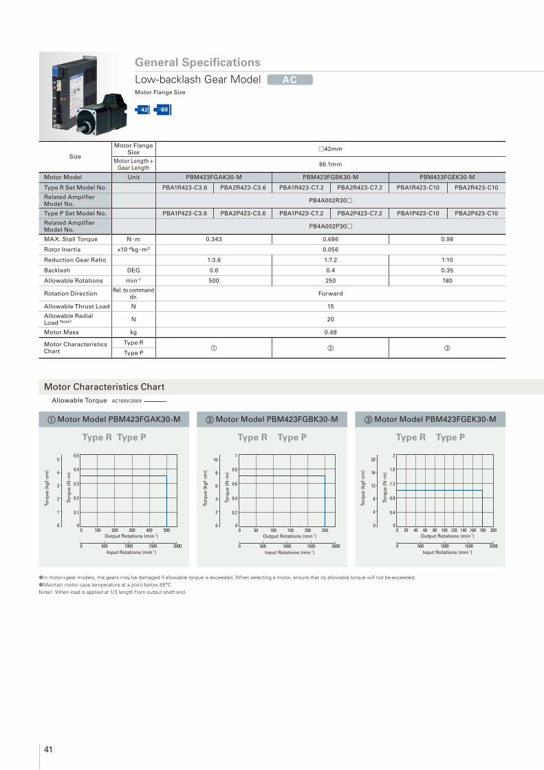
41
Allowable Torque AC100V/200V
□42 □60
*In motor+gear models, the gears may be damaged if allowable torque is exceeded. When selecting a motor, ensure that its allowable torque will not be exceeded.*Maintain motor case temperature at a point below 85°C.Note1: When load is applied at 1/3 length from output shaft end.
① Motor Model PBM423FGAK30-M ③ Motor Model PBM423FGEK30-M
Type R Type P Type R Type P
② Motor Model PBM423FGBK30-M
Type R Type P
Size
Motor Flange Size
□42mm
Motor Length + Gear Length
86.1mm
Motor Model Unit PBM423FGAK30-M PBM423FGBK30-M PBM423FGEK30-M
Type R Set Model No. PBA1R423-C3.6 PBA2R423-C3.6 PBA1R423-C7.2 PBA2R423-C7.2 PBA1R423-C10 PBA2R423-C10
Related Amplifi er Model No.
PB4A002R30□
Type P Set Model No. PBA1P423-C3.6 PBA2P423-C3.6 PBA1P423-C7.2 PBA2P423-C7.2 PBA1P423-C10 PBA2P423-C10
Related Amplifi er Model No.
PB4A002P30□
MAX. Stall Torque N · m 0.343 0.686 0.98
Rotor Inertia ×10-4kg · m2 0.056
Reduction Gear Ratio 1:3.6 1:7.2 1:10
Backlash DEG 0.6 0.4 0.35
Allowable Rotations min-1 500 250 180
Rotation DirectionRel. to command
dir.Forward
Allowable Thrust Load N 15
Allowable Radial Load Note1 N 20
Motor Mass kg 0.48
Motor Characteristics Chart
Type R① ② ③
Type P
To
rqu
e (
N·m
)
To
rqu
e (
kg
f·cm
)
0.1
0.2
0.3
0.4
0.5
1
2
3
4
5
00 0
100 200 300 400 500
0 500 1000 1500 2000
Output Rotations (min-1)
Input Rotations (min-1)
To
rqu
e (
N·m
)
To
rqu
e (
kg
f·cm
)
0.2
0.4
0.6
0.8
1
2
4
6
8
10
00 0
50 100 150 200 250
0 500 1000 1500 2000
Output Rotations (min-1)
Input Rotations (min-1)
To
rqu
e (
N·m
)
To
rqu
e (
kg
f·cm
)
0.4
0.8
1.2
1.6
2
4
8
12
16
20
2000 0
40 60 80 120 140 180160 200100
0 500 1000 1500 2000
Output Rotations (min-1)
Input Rotations (min-1)
General Specifi cations
Low-backlash Gear Model AC
Motor Flange Size
Motor Characteristics Chart
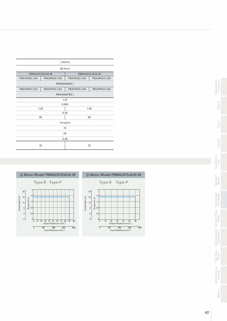
42
Fe
atu
res a
nd
Fu
ncti
on
sT
yp
e R
Ty
pe P
Ty
pe M
Ha
rmo
nic
Ge
ar
Mo
de
lT
yp
e R
Mu
lti-
Ax
isE
lectr
om
ag
ne
tic
Bra
ke
Mo
de
lS
pu
r G
ea
r M
od
el
Sta
nd
ard
M
od
el
Mo
tor
Dim
en
sio
na
l D
raw
ing
s
Lo
w-b
ackla
sh
G
ear
Mo
del
Op
tio
ns
④ Motor Model PBM423FGGK30-M
Type R Type P
⑤ Motor Model PBM423FGJK30-M
Type R Type P
□42mm
86.1mm
PBM423FGGK30-M PBM423FGJK30-M
PBA1R423-C20 PBA2R423-C20 PBA1R423-C30 PBA2R423-C30
PB4A002R30□
PBA1P423-C20 PBA2P423-C20 PBA1P423-C30 PBA2P423-C30
PB4A002P30□
1.47
0.056
1:20 1:30
0.25
90 60
Forward
15
20
0.48
④ ⑤
To
rqu
e (
N·m
)
To
rqu
e (
kg
f·cm
)
0.4
0.8
1.2
1.6
2
4
8
12
16
20
1000 0
20 30 40 60 70 9080 10050
0 500 1000 1500 2000
Output Rotations (min-1)
Input Rotations (min-1)
100 20 30 50 6040Output Rotations (min
-1)
0 500 1000 1500 2000Input Rotations (min
-1)
To
rqu
e (
N·m
)
To
rqu
e (
kg
f·cm
)
0.4
0.8
1.2
1.6
2
4
8
12
16
20
0 0

43
Allowable Torque AC100V/200V
□42 □60
*In motor+gear models, the gears may be damaged if allowable torque is exceeded. When selecting a motor, ensure that its allowable torque will not be exceeded.*Maintain motor case temperature at a point below 85°C.Note1: When load is applied at 1/3 length from output shaft end.
① Motor Model PBM603FGAK30-M ③ Motor Model PBM603FGEK30-M
Type R Type P Type R Type P
② Motor Model PBM603FGBK30-M
Type R Type P
To
rqu
e (
N·m
)
To
rqu
e (
kg
f·cm
)
0.4
0.8
1.2
1.6
2
4
8
12
16
20
00 0
100 200 300 400 500
0 500 1000 1500 2000
Output Rotations (min-1)
Input Rotations (min-1)
To
rqu
e (
N·m
)
To
rqu
e (
kg
f·cm
)
1
2
3
4
5
10
20
30
40
50
00 0
50 100 150 200 250
0 500 1000 1500 2000
Output Rotations (min-1)
Input Rotations (min-1)
To
rqu
e (
N·m
)
To
rqu
e (
kg
f·cm
)
1
2
3
4
5
10
20
30
40
50
2000 0
40 60 80 120 140 180160 200100
0 500 1000 1500 2000
Output Rotations (min-1)
Input Rotations (min-1)
General Specifi cations
Low-backlash Gear Model AC
Motor Flange Size
Motor Characteristics Chart
Size
Motor Flange
Size□60mm
Motor Length +
Gear Length114.3mm
Motor Model Unit PBM603FGAK30-M PBM603FGBK30-M PBM603FGEK30-M
Type R Set Model No. PBA1R603-C3.6 PBA2R603-C3.6 PBA1R603-C7.2 PBA2R603-C7.2 PBA1R603-C10 PBA2R603-C10
Related Amplifi er Model No.
PB4A002R30□
Type P Set Model No. PBA1P603-C3.6 PBA2P603-C3.6 PBA1P603-C7.2 PBA2P603-C7.2 PBA1P603-C10 PBA2P603-C10
Related Amplifi er Model No.
PB4A002P30□
MAX. Stall Torque N · m 1.25 2.5 3
Rotor Inertia ×10-4kg · m2 0.4
Reduction Gear Ratio 1:3.6 1:7.2 1:10
Backlash DEG 0.55 0.25
Allowable Rotations min-1 500 250 180
Rotation DirectionRel. to command
dir.Forward Reverse
Allowable Thrust Load N 30
Allowable Radial Load Note1 N 100
Motor Mass kg 1.22
Motor Characteristics Chart
Type R① ② ③
Type P

44
Fe
atu
res a
nd
Fu
ncti
on
sT
yp
e R
Ty
pe P
Ty
pe M
Ha
rmo
nic
Ge
ar
Mo
de
lT
yp
e R
Mu
lti-
Ax
isE
lectr
om
ag
ne
tic
Bra
ke
Mo
de
lS
pu
r G
ea
r M
od
el
Sta
nd
ard
M
od
el
Mo
tor
Dim
en
sio
na
l D
raw
ing
s
Lo
w-b
ackla
sh
G
ear
Mo
del
Op
tio
ns
④ Motor Model PBM603FGGK30-M
Type R Type P
⑤ Motor Model PBM603FGJK30-M
Type R Type P
□60mm
114.3mm
PBM603FGGK30-M PBM603FGJK30-M
PBA1R603-C20 PBA2R603-C20 PBA1R603-C30 PBA2R603-C30
PB4A002R30□
PBA1P603-C20 PBA2P603-C20 PBA1P603-C30 PBA2P603-C30
PB4A002P30□
3.5 4
0.4
1:20 1:30
0.17
90 60
Reverse
30
100
1.22
④ ⑤
To
rqu
e (
N·m
)
To
rqu
e (
kg
f·cm
)
1
2
3
4
5
10
20
30
40
50
1000 0
20 30 40 60 70 9080 10050
0 500 1000 1500 2000
Output Rotations (min-1)
Input Rotations (min-1)
100 20 30 50 6040
0 500 1000 1500 2000
To
rqu
e (
N·m
)
To
rqu
e (
kg
f·cm
)
1
2
3
4
5
10
20
30
40
50
0 0
Output Rotations (min-1)
Input Rotations (min-1)

45
Type M Allowable Torque DC24V DC48V DC24V/48V
Type R Multi-Axis Allowable Torque DC24V DC36V DC24V/36V
*In motor+gear models, the gears may be damaged if allowable torque is exceeded. When selecting a motor, ensure that its allowable torque will not be exceeded.*Maintain motor case temperature at a point below 85°C.Note1: When load is applied at 1/3 length from output shaft end.
□42 □60
① Motor Model PBM423FGAE20
②Motor Model PBM423DGAA20
⑤ Motor Model PBM423FGEE20
⑥ Motor Model PBM423DGEA20
Type M
Type R Multi-Axis
Type M
Type R Multi-Axis
③ Motor Model PBM423FGBE20
④ Motor Model PBM423DGBA20
Type M
Type R Multi-Axis
To
rqu
e (
N·m
)
To
rqu
e (
kg
f·cm
)
0.4
0.8
1.2
1.6
2
4
8
12
16
20
00 0
100 200 300 400 500
0 500 1000 1500 2000
Output Rotations (min-1)
Input Rotations (min-1)
To
rqu
e (
N·m
)
To
rqu
e (
kg
f·cm
)
0.4
0.8
1.2
1.6
2
4
8
12
16
20
00 0
50 100 150 200 250
0 500 1000 1500 2000
Output Rotations (min-1)
Input Rotations (min-1)
To
rqu
e (
N·m
)
To
rqu
e (
kg
f·cm
)
0.4
0.8
1.2
1.6
2
4
8
12
16
20
00 0
20 40 8060 100 140 160 200120 180
0 500 1000 1500 2000
Output Rotations (min-1)
Input Rotations (min-1)
To
rqu
e (
N·m
)
To
rqu
e (
kg
f·cm
)
0.4
0.8
1.2
1.6
2
4
8
12
16
20
00 0
100 200 300 400 500
0 500 1000 1500 2000
Output Rotations (min-1)
Input Rotations (min-1)
To
rqu
e (
N·m
)
To
rqu
e (
kg
f·cm
)
0.4
0.8
1.2
1.6
2
4
8
12
16
20
00 0
50 100 150 200 250
0 500 1000 1500 2000
Output Rotations (min-1)
Input Rotations (min-1)
To
rqu
e (
N·m
)
To
rqu
e (
kg
f·cm
)
0.4
0.8
1.2
1.6
2
4
8
12
16
20
00 0
20 40 8060 100 140 160 200120 180
0 500 1000 1500 2000
Output Rotations (min-1)
Input Rotations (min-1)
General Specifi cations
Low-backlash Gear Model DC
Motor Flange Size
Motor Characteristics Chart
Size
Motor Flange Size
□42mm
Motor Length + Gear Length
87.9mm
Motor Model Unit PBM423FGAE20 PBM423FGBE20 PBM423FGEE20
Type M Set Model No. PBDM423-C3.6 PBDM423-C7.2 PBDM423-C10
Related Amplifi er Model No.
PB3D003M200
Motor Model Unit PBM423DGAA20 PBM423DGBA20 PBM423DGEA20
Type R Multi-axis Model No.
PB2D003R1U△
MAX. Stall Torque N · m 0.343 0.686 0.98
Rotor Inertia ×10-4kg · m2 0.056
Reduction Gear Ratio 1:3.6 1:7.2 1:10
Backlash DEG 0.6 0.4 0.35
Allowable Rotations min-1 500 250 180
Rotation DirectionRel. to command
dir.Forward
Allowable Thrust Load N 15
Allowable Radial Load Note1 N 20
Motor Mass kg 0.48
Motor Characteristics Chart
Type M ① ③ ⑤
Type R Multi-Axis ② ④ ⑥

46
Fe
atu
res a
nd
Fu
ncti
on
sT
yp
e R
Ty
pe P
Ty
pe M
Ha
rmo
nic
Ge
ar
Mo
de
lT
yp
e R
Mu
lti-
Ax
isE
lectr
om
ag
ne
tic
Bra
ke
Mo
de
lS
pu
r G
ea
r M
od
el
Sta
nd
ard
M
od
el
Mo
tor
Dim
en
sio
na
l D
raw
ing
s
Lo
w-b
ackla
sh
G
ear
Mo
del
Op
tio
ns
⑦ Motor Model PBM423FGGE20
⑧ Motor Model PBM423DGGA20
Type M
Type R Multi-Axis
⑨ Motor Model PBM423FGJE20
⑩ Motor Model PBM423DGJA20
Type M
Type R Multi-Axis
□42mm
87.9mm
PBM423FGGE20 PBM423FGJE20
PBDM423-C20 PBDM423-C30
PB3D003M200
PBM423DGGA20 PBM423DGJA20
PB2D003R1U△
1.47
0.056
1:20 1:30
0.25 0.25
90 60
Reverse
15
20
0.48
⑦ ⑨
⑧ ⑩
To
rqu
e (
N·m
)
To
rqu
e (
kg
f·cm
)
0.4
0.8
1.2
1.6
2
4
8
12
16
20
00 0
302010 40 50 60
0 500 1000 1500 2000
Output Rotations (min-1)
Input Rotations (min-1)
To
rqu
e (
N·m
)
To
rqu
e (
kg
f·cm
)
0.4
0.8
1.2
1.6
2
4
8
12
16
20
00 0
10 20 4030 50 70 80 10060 90
0 500 1000 1500 2000
Output Rotations (min-1)
Input Rotations (min-1)
To
rqu
e (
N·m
)
To
rqu
e (
kg
f·cm
)
0.4
0.8
1.2
1.6
2
4
8
12
16
20
00 0
302010 40 50 60
0 500 1000 1500 2000
Output Rotations (min-1)
Input Rotations (min-1)
To
rqu
e (
N·m
)
To
rqu
e (
kg
f·cm
)
0.4
0.8
1.2
1.6
2
4
8
12
16
20
00 0
10 20 4030 50 70 80 10060 90
0 500 1000 1500 2000
Output Rotations (min-1)
Input Rotations (min-1)

47
Type M Allowable Torque DC24V DC48V DC24V/48V
Type R Multi-Axis Allowable Torque DC24V DC36V DC24V/36V
*In motor+gear models, the gears may be damaged if allowable torque is exceeded. When selecting a motor, ensure that its allowable torque will not be exceeded.*Maintain motor case temperature at a point below 85°C.Note1: When load is applied at 1/3 length from output shaft end.
□42 □60
① Motor Model PBM603FGAE20
②Motor Model PBM603DGAA20
⑤ Motor Model PBM603FGEE20
⑥ Motor Model PBM603DGEA20
Type M
Type R Multi-Axis
Type M
Type R Multi-Axis
③ Motor Model PBM603FGBE20
④ Motor Model PBM603DGBA20
Type M
Type R Multi-Axis
To
rqu
e (
N·m
)
To
rqu
e (
kg
f·cm
)
1
2
3
4
5
10
20
30
40
50
00 0
100 200 300 400 500
0 500 1000 1500 2000
Output Rotations (min-1)
Input Rotations (min-1)
To
rqu
e (
N·m
)
To
rqu
e (
kg
f·cm
)
1
2
3
4
5
10
20
30
40
50
00 0
50 100 150 200 250
0 500 1000 1500 2000
Output Rotations (min-1)
Input Rotations (min-1)
To
rqu
e (
N·m
)
To
rqu
e (
kg
f·cm
)
1
2
3
4
5
10
20
30
40
50
2000 0
40 60 80 120 140 180160 200100
0 500 1000 1500 2000
Output Rotations (min-1)
Input Rotations (min-1)
0 100 200 400 500300
5000 1000 1500 2000
To
rqu
e (
kg
f·cm
)
10
20
30
40
50
0
To
rqu
e (
N·m
)
1
2
3
4
5
0
Output Rotations (min-1)
Input Rotations (min-1)
0 50 100 200 250150
5000 1000 1500 2000
To
rqu
e (
kg
f·cm
)
10
20
30
40
50
0
To
rqu
e (
N·m
)
1
2
3
4
5
0
Output Rotations (min-1)
Input Rotations (min-1)
To
rqu
e (
N·m
)
To
rqu
e (
kg
f·cm
)
1
2
3
4
5
10
20
30
40
50
00 0
20 40 8060 100 140 160 200120 180
0 500 1000 1500 2000
Output Rotations (min-1)
Input Rotations (min-1)
General Specifi cations
Low-backlash Gear Model DC
Motor Flange Size
Motor Characteristics Chart
Size
Motor Flange Size
□60mm
Motor Length + Gear Length
115.8mm
Motor Model Unit PBM603FGAE20 PBM603FGBE20 PBM603FGEE20
Type M Set Model No. PBDM603-C3.6 PBDM603-C7.2 PBDM603-C10
Related Amplifi er Model No.
PB3D003M200
Motor Model Unit PBM603DGAA20 PBM603DGBA20 PBM603DGEA20
Type R Multi-axis Model No.
PB2D003R1U△
MAX. Stall Torque N · m 1.25 2.5 3
Rotor Inertia ×10-4kg · m2 0.4
Reduction Gear Ratio 1:3.6 1:7.2 1:10
Backlash DEG 0.55 0.25
Allowable Rotations min-1 500 250 180
Rotation DirectionRel. to command
dir.Forward Reverse
Allowable Thrust Load N 30
Allowable Radial Load Note1 N 100
Motor Mass kg 1.22
Motor Characteristics Chart
Type M ① ③ ⑤
Type R Multi-Axis ② ④ ⑥

48
Fe
atu
res a
nd
Fu
ncti
on
sT
yp
e R
Ty
pe P
Ty
pe M
Ha
rmo
nic
Ge
ar
Mo
de
lT
yp
e R
Mu
lti-
Ax
isE
lectr
om
ag
ne
tic
Bra
ke
Mo
de
lS
pu
r G
ea
r M
od
el
Sta
nd
ard
M
od
el
Mo
tor
Dim
en
sio
na
l D
raw
ing
s
Lo
w-b
ackla
sh
G
ear
Mo
del
Op
tio
ns
⑦ Motor Model PBM603FGGE20
⑧ Motor Model PBM603DGGA20
Type M
Type R Multi-Axis
⑨ Motor Model PBM603FGJE20
⑩ Motor Model PBM603DGJA20
Type M
Type R Multi-Axis
□60mm
115.8mm
PBM603FGGE20 PBM603FGJE20
PBDM603-C20 PBDM603-C30
PB3D003M200
PBM603DGGA20 PBM603DGJA20
PB2D003R1U△
3.5 4
0.4
1:20 1:30
0.17
90 60
Reverse
30
100
1.22
⑦ ⑨
⑧ ⑩
To
rqu
e (
N·m
)
To
rqu
e (
kg
f·cm
)
1
2
3
4
5
10
20
30
40
50
00 0
10 20 4030 50 70 80 10060 90
0 500 1000 1500 2000
Output Rotations (min-1)
Input Rotations (min-1)
To
rqu
e (
N·m
)
To
rqu
e (
kg
f·cm
)
1
2
3
4
5
10
20
30
40
50
00 0
302010 40 50 60
0 500 1000 1500 2000
Output Rotations (min-1)
Input Rotations (min-1)
To
rqu
e (
N·m
)
To
rqu
e (
kg
f·cm
)
1
2
3
4
5
10
20
30
40
50
1000 0
20 30 40 60 70 9080 10050
0 500 1000 1500 2000
Output Rotations (min-1)
Input Rotations (min-1)
To
rqu
e (
N·m
)
To
rqu
e (
kg
f·cm
)
1
2
3
4
5
10
20
30
40
50
00 0
302010 40 50 60
0 500 1000 1500 2000
Output Rotations (min-1)
Input Rotations (min-1)

49
Allowable Torque Single-phase AC100V/200V Allow. Instantaneous Torque Single-phase, 3-phase AC100V/200V
□42 □60
*In motor+gear models, the gears may be damaged if allowable torque is exceeded. When selecting a motor, ensure that its allowable torque will not be exceeded.*Maintain motor case temperature at a point below 85°C.*The gear output shaft rotates in the opposite direction.Note1: When load is applied at 1/3 length from output shaft end.
① Motor Model PBM423FHJK30-M ③ Motor Model PBM423FHMK30-M
Type R Type P Type R Type P
② Motor Model PBM423FHLK30-M
Type R Type P
To
rqu
e (
N·m
)
To
rqu
e (
kg
f·cm
)
2
4
6
8
10
20
40
60
80
100
00 0
20 40 60 80 100 120 140
5000 1000 1500 2000 3000 3500 4000 45002500
Output Rotations (min-1)
Input Rotations (min-1)
To
rqu
e (
N·m
)
To
rqu
e (
kg
f·cm
)
2
4
6
8
10
20
40
60
80
100
1000 0
20 30 40 60 70 80 9050
5000 1000 1500 2000 3000 3500 4000 45002500
Output Rotations (min-1)
Input Rotations (min-1)
To
rqu
e (
N·m
)
To
rqu
e (
kg
f·cm
)
4
8
12
16
20
40
80
120
160
200
500 0
10 15 20 30 35 40 4525
5000 1000 1500 2000 3000 3500 4000 45002500
Output Rotations (min-1)
Input Rotations (min-1)
General Specifi cations
Harmonic Gear Model AC
Motor Flange Size
Motor Characteristics Chart
Size
Motor Flange Size
□42mm
Motor Length + Gear Length
95.1mm
Motor Model Unit PBM423FHJK30-M PBM423FHLK30-M PBM423FHMK30-M
Type R Set Model No. PBA1R423-H30 / PBA2R423-H30 PBA1R423-H50 / PBA2R423-H50 PBA1R423-H100 / PBA2R423-H100
Related Amplifi er Model No.
PB4A002R30□
Type P Set Model No. PBA1P423-H30 / PBA2P423-H30 PBA1P423-H50 / PBA2P423-H50 PBA1P423-H100 / PBA2P423-H100
Related Amplifi er Model No.
PB4A002P30□
MAX. Stall Torque N · m 2.2 3.5 5
Allow. Instantaneous Torque
N · m 4.5 8.3 11
Rotor Inertia ×10-4kg · m2 0.068
Reduction Gear Ratio 1:30 1:50 1:100
Lost Motion min −
Hysteresis Loss min 3.6 2.4
Allowable Rotations min-1 116 70 35
Allowable Thrust Load N 1150
Allowable Radial Load Note1 N 209
Motor Mass kg 0.54
Motor Characteristics Chart
Type R① ② ③
Type P

50
Fe
atu
res a
nd
Fu
ncti
on
sT
yp
e R
Ty
pe P
Ty
pe M
Ha
rmo
nic
Ge
ar
Mo
de
lT
yp
e R
Mu
lti-
Ax
isE
lectr
om
ag
ne
tic
Bra
ke
Mo
de
lS
pu
r G
ea
r M
od
el
Sta
nd
ard
M
od
el
Mo
tor
Dim
en
sio
na
l D
raw
ing
s
Lo
w-b
ackla
sh
G
ear
Mo
del
Op
tio
ns
④ Motor Model PBM603FHLK30-M
Type R Type P
⑤ Motor Model PBM603FHMK30-M
Type R Type P
□60mm
135.8mm
PBM603FHLK30-M PBM603FHMK30-M
PBA1R603-H50 / PBA2R603-H50 PBA1R603-H100 / PBA2R603-H100
PB4A002R30□
PBA1P603-H50 / PBA2P603-H50 PBA1P603-H100 / PBA2P603-H100
PB4A002P30□
5.5 8
14 20
0.435
1:50 1:100
0.4 to 3 [±0.28N · m] 0.4 to 3 [±0.4N · m]
−
70 35
400
360
1.45
④ ⑤
To
rqu
e (
N·m
)
To
rqu
e (
kg
f·cm
)
4
8
12
16
20
40
80
120
160
200
1000 0
20 30 40 60 70 80 9050
5000 1000 1500 2000 3000 3500 4000 45002500
Output Rotations (min-1)
Input Rotations (min-1)
To
rqu
e (
N·m
)
To
rqu
e (
kg
f·cm
)
10
20
30
40
50
100
200
300
400
500
500 0
10 15 20 30 35 40 4525
5000 1000 1500 2000 3000 3500 4000 45002500
Output Rotations (min-1)
Input Rotations (min-1)

51
*In motor+gear models, the gears may be damaged if allowable torque is exceeded. When selecting a motor, ensure that its allowable torque will not be exceeded.*Maintain motor case temperature at a point below 85°C. *The gear output shaft rotates in the opposite direction. Note1: When load is applied at 1/3 length from output shaft end.
□28 □42
① Motor Model PBM282FHLE20
②Motor Model PBM282DHLA20
⑤ Motor Model PBM423FHJE20
⑥ Motor Model PBM423DHJA20
Type M
Type R Multi-Axis
Type M
Type R Multi-Axis
③ Motor Model PBM282FHME20
④ Motor Model PBM282DHMA20
Type M
Type R Multi-Axis
To
rqu
e (
N·m
)
To
rqu
e (
kg
f·cm
)
1
2
3
4
5
10
20
30
40
50
1000 0
20 30 40 60 70 80 9050
5000 1000 1500 2000 3000 3500 4000 45002500
Output Rotations (min-1)
Input Rotations (min-1)
To
rqu
e (
N·m
)
To
rqu
e (
kg
f·cm
)
1
2
3
4
5
10
20
30
40
50
500 0
10 15 20 30 35 40 4525
5000 1000 1500 2000 3000 3500 4000 45002500
Output Rotations (min-1)
Input Rotations (min-1)
To
rqu
e (
N·m
)
To
rqu
e (
kg
f·cm
)
4
8
12
16
20
40
80
120
160
200
00 0
20 40 60 80 100 120 140
5000 1000 1500 2000 3000 3500 4000 45002500
Output Rotations (min-1)
Input Rotations (min-1)
To
rqu
e (
N·m
)
To
rqu
e (
kg
f·cm
)
1
2
3
4
5
10
20
30
40
50
500 0
10 15 20 30 35 40 4525
5000 1000 1500 2000 3000 3500 4000 45002500
Output Rotations (min-1)
Input Rotations (min-1)
To
rqu
e (
N·m
)
To
rqu
e (
kg
f·cm
)
4
8
12
16
20
40
80
120
160
200
00 0
20 40 60 80 100 120 140
5000 1000 1500 2000 3000 3500 4000 45002500
Output Rotations (min-1)
Input Rotations (min-1)
General Specifi cations
Harmonic Gear Model DC
Motor Flange Size
Motor Characteristics Chart
To
rqu
e (
N·m
)
To
rqu
e (
kg
f·cm
)
1
2
3
4
5
10
20
30
40
50
1000 0
20 30 40 60 70 80 9050
5000 1000 1500 2000 3000 3500 4000 45002500
Output Rotations (min-1)
Input Rotations (min-1)
Type M Allowable Torque DC24V DC48V DC24V/48V Allow. Instantaneous Torque DC24V DC48V DC24V/48V
Type R Multi-Axis Allowable Torque DC24V DC36V DC24V+36V Allow. Instantaneous Torque DC24V DC36V DC24V/36V
Size
Motor Flange Size
□28mm □42mm
Motor Length + Gear Length
97mm 97mm
Motor Model Unit PBM282FHLE20 PBM282FHME20 PBM423FHJE20
Type M Set Model No. PBDM282-H50 PBDM282-H100 PBDM423-H30
Related Amplifi er Model No.
PB3D003M200
Motor Model Unit PBM282DHLA20 PBM282DHMA20 PBM423DHJA20
Type R Multi-axis Model No.
PB2D003R1U△
MAX. Stall Torque N · m 1.5 2 2.2
Allow. Instantaneous Torque
N · m 2.7 3.6 4.5
Rotor Inertia ×10-4kg · m2 0.012 0.068
Reduction Gear Ratio 1:50 1:100 1:30
Lost Motion min 0.4 to 3 [±0.06N · m] 0.4 to 3 [±0.08N · m] −
Hysteresis Loss min − − 3.6
Allowable Rotations min-1 70 35 116
Allowable Thrust Load N 100 1150
Allowable Radial Load Note1 N 160 209
Motor Mass kg 0.27 0.54
Motor Characteristics Chart
Type M ① ③ ⑤
Type R Multi-Axis ② ④ ⑥

52
Fe
atu
res a
nd
Fu
ncti
on
sT
yp
e R
Ty
pe P
Ty
pe M
Ha
rmo
nic
Ge
ar
Mo
de
lT
yp
e R
Mu
lti-
Ax
isE
lectr
om
ag
ne
tic
Bra
ke
Mo
de
lS
pu
r G
ea
r M
od
el
Sta
nd
ard
M
od
el
Mo
tor
Dim
en
sio
na
l D
raw
ing
s
Lo
w-b
ackla
sh
G
ear
Mo
del
Op
tio
ns
⑦ Motor Model PBM423FHLE20
⑧ Motor Model PBM423DHLA20
Type M
Type R Multi-Axis
⑨ Motor Model PBM423FHME20
⑩ Motor Model PBM423DHMA20
Type M
Type R Multi-Axis
□42mm
97mm
PBM423FHLE20 PBM423FHME20
PBDM423-H50 PBDM423-H100
PB3D003M200
PBM423DHLA20 PBM423DHMA20
PB2D003R1U△
3.5 5
8.3 11
0.068
1:50 1:100
−
2.4
70 35
1150
209
0.54
⑦ ⑨
⑧ ⑩
To
rqu
e (
N·m
)
To
rqu
e (
kg
f·cm
)
4
8
12
16
20
40
80
120
160
200
1000 0
20 30 40 60 70 80 9050
5000 1000 1500 2000 3000 3500 4000 45002500
Output Rotations (min-1)
Input Rotations (min-1)
To
rqu
e (
N·m
)
To
rqu
e (
kg
f·cm
)
4
8
12
16
20
40
80
120
160
200
1000 0
20 30 40 60 70 80 9050
5000 1000 1500 2000 3000 3500 4000 45002500
Output Rotations (min-1)
Input Rotations (min-1)
To
rqu
e (
N·m
)
To
rqu
e (
kg
f·cm
)
4
8
12
16
20
40
80
120
160
200
500 0
10 15 20 30 35 40 4525
5000 1000 1500 2000 3000 3500 4000 45002500
Output Rotations (min-1)
Input Rotations (min-1)
To
rqu
e (
N·m
)
To
rqu
e (
kg
f·cm
)
4
8
12
16
20
40
80
120
160
200
500 0
10 15 20 30 35 40 4525
5000 1000 1500 2000 3000 3500 4000 45002500
Output Rotations (min-1)
Input Rotations (min-1)

53
Type M Allowable Torque DC24V DC48V DC24V/48V Allow. Instantaneous Torque DC24V DC48V DC24V/48V
Type R Multi-Axis Allowable Torque DC24V DC36V DC24V+36V Allow. Instantaneous Torque DC24V DC36V DC24V/36V
General Specifi cations
Harmonic Gear Model DC
Motor Flange Size
*In motor+gear models, the gears may be damaged if allowable torque is exceeded. When selecting a motor, ensure that its allowable torque will not be exceeded.
*Maintain motor case temperature at a point below 85°C.*The gear output shaft rotates in the opposite direction.Note1: When load is applied at 1/3 length from output shaft
end.
Motor Characteristics Chart
□60
① Motor Model PBM603FHLE20
②Motor Model PBM603DHLA20
Type M
Type R Multi-Axis
③ Motor Model PBM603FHME20
④ Motor Model PBM603DHMA20
Type M
Type R Multi-Axis
To
rqu
e (
N·m
)
To
rqu
e (
kg
f·cm
)
10
20
30
40
50
100
200
300
400
500
1000 0
20 30 40 60 70 80 9050
5000 1000 1500 2000 3000 3500 4000 45002500
Output Rotations (min-1)
Input Rotations (min-1)
To
rqu
e (
N·m
)
To
rqu
e (
kg
f·cm
)
10
20
30
40
50
100
200
300
400
500
1000 0
20 30 40 60 70 80 9050
5000 1000 1500 2000 3000 3500 4000 45002500
Output Rotations (min-1)
Input Rotations (min-1)
To
rqu
e (
N·m
)
To
rqu
e (
kg
f·cm
)
20
30
40
50
100
200
300
400
500
500 0
10 15 20 30 35 40 4525
5000 1000 1500 2000 3000 3500 4000 45002500
Output Rotations (min-1)
Input Rotations (min-1)
10
To
rqu
e (
N·m
)
To
rqu
e (
kg
f·cm
)
10
20
30
40
50
100
200
300
400
500
500 0
10 15 20 30 35 40 4525
5000 1000 1500 2000 3000 3500 4000 45002500
Output Rotations (min-1)
Input Rotations (min-1)
Size
Motor Flange Size
□60mm
Motor Length + Gear Length
137.3mm
Motor Model Unit PBM603FHLE20 PBM603FHME20
Type M Set Model No. PBDM603-H50 PBDM603-H100
Related Amplifi er Model No.
PB3D003M200
Motor Model Unit PBM603DHLA20 PBM603DHMA20
Type R Multi-axis Model No.
PB2D003R1U△
MAX. Stall Torque N · m 5.5 8
Allow. Instantaneous Torque
N · m 14 20
Rotor Inertia ×10-4kg · m2 0.435
Reduction Gear Ratio 1:50 1:100
Lost Motion min 0.4 to 3 [±0.28N · m] 0.4 to 3 [±0.4N · m]
Hysteresis Loss min −
Allowable Rotations min-1 70 35
Allowable Thrust Load N 400
Allowable Radial Load Note1 N 360
Motor Mass kg 1.45
Motor Characteristics Chart
Type M ① ③
Type R Multi-Axis ② ④

54
Fe
atu
res a
nd
Fu
ncti
on
sT
yp
e R
Ty
pe P
Ty
pe M
Ha
rmo
nic
Ge
ar
Mo
de
lT
yp
e R
Mu
lti-
Ax
isE
lectr
om
ag
ne
tic
Bra
ke
Mo
de
lS
pu
r G
ea
r M
od
el
Sta
nd
ard
M
od
el
Mo
tor
Dim
en
sio
na
l D
raw
ing
s
Lo
w-b
ackla
sh
G
ear
Mo
del
Op
tio
ns
Torque AC100V/200V Power Consumption Single-phase AC100V Single-phase AC200V 3-phase AC200V
□42 □60
General Specifi cations
Electromagnetic Brake Model AC
Motor Flange Size
The electromagnetic brake only works when the motor is stopped, and cannot be used for braking.*Maintain motor case temperature at a point below 85°C.Note1: When load is applied output shaft end.
Motor Characteristics Chart
① Motor Model PBM423FCK30-M ③ Motor Model PBM604FCK30-M
Type R Type P Type R Type P
② Motor Model PBM603FCK30-M
Type R Type P
To
rqu
e (
N·m
)
0.5
1.0
2.0
2.5
3
5000
2
4
8
10
12
001000 1500 2000 3000 3500 4000 45002500
1.5 6
Rotations (min-1)
Po
we
r C
on
su
mp
tio
n (
A)
To
rqu
e (
kg
f·cm
)
5
10
20
25
30
0
15
To
rqu
e (
N·m
)
0.4
0.8
1.2
1.6
2
5000
2
4
6
8
10
001000 1500 2000 3000 3500 4000 45002500
Rotations (min-1)
Po
we
r C
on
su
mp
tio
n (
A)
To
rqu
e (
kg
f·cm
)
4
8
12
16
20
0
To
rqu
e (
N·m
)
0.1
0.2
0.3
0.4
0.5
50000
1000 1500 2000 3000 3500 4000 45002500 Rotations (min
-1)
Po
we
r C
on
su
mp
tio
n (
A)
1
2
4
5
6
0
3
To
rqu
e (
kg
f·cm
)
1
2
3
4
5
0
Size
Motor Flange Size
□42mm □60mm
Motor Length + Brake Length
88.3mm 113.6mm 145.6mm
Motor Model Unit PBM423FCK30-M PBM603FCK30-M PBM604FCK30-M
Type R Set Model No.
PBA1R423-B PBA2R423-B PBA1R603-B PBA2R603-B PBA1R604-B PBA2R604-B
Related Amplifi er Model No.
PB4A002R30□
Type P Set Model No.
PBA1P423-B PBA2P423-B PBA1P603-B PBA2P603-B PBA1P604-B PBA2P604-B
Related Amplifi er Model No.
PB4A002P30□
MAX. Stall Torque N · m 0.39 1.3 1.9
Rotor Inertia ×10-4kg · m2 0.056 0.4 0.84
Allowable Thrust Load
N 9.8 14.7
Allowable Radial Load Note1 N 47 190
Motor Mass kg 0.5 1.19 1.76
Ele
ctr
om
ag
ne
tic B
rake
Operation Method
No excitation actuating type
Power Voltage V DC24V±5%
Excitation Current
A 0.08 0.25
Power Consumption
W 2 6
Friction Torque N · m 0.3 0.78
Brake Engaging Time
ms 20 20
Brake Release Time
ms 30 30
Motor Characteris-tics Chart
Type R① ② ③
Type P

55
To
rqu
e (
N·m
)
To
rqu
e (
kg
f·cm
)
0.02
0.04
0.06
0.08
0.1
0.2
0.4
0.6
0.8
1
50000 0
1000 1500 2000 3000 3500 4000 45002500 Rotations (min
-1)
To
rqu
e (
N·m
)
To
rqu
e (
kg
f·cm
)
0.04
0.08
0.12
0.16
0.2
0.4
0.8
1.2
1.6
2
50000 0
1000 1500 2000 3000 3500 4000 45002500 Rotations (min
-1)
Type M Torque DC24V DC48V Power Consumption DC24V DC48V
Type R Multi-Axis Torque DC24V DC36V
The electromagnetic brake only works when the motor is stopped, and cannot be used for braking.*Maintain motor case temperature at a point below 85°C.Note1: When load is applied at 1/3 length from output shaft end.
① Motor Model PBM282FCE20
②Motor Model PBM282DCA20
⑤ Motor Model PBM423FCE20
⑥ Motor Model PBM423DCA20
Type M
Type R Multi-Axis
Type M
Type R Multi-Axis
③ Motor Model PBM284FCE20
④ Motor Model PBM284DCA20
Type M
Type R Multi-Axis
□28 □42 □60
To
rqu
e (
N·m
)
0.02
0.04
0.06
0.08
0.1
5000
2
4
6
8
10
001000 1500 2000 3000 3500 4000 45002500
Rotations (min-1)
Po
we
r C
on
su
mp
tio
n (
A)
To
rqu
e (
kg
f·cm
)
0.2
0.4
0.6
0.8
1
0
To
rqu
e (
N·m
)
0.04
0.08
0.12
0.16
0.2
50000
1000 1500 2000 3000 3500 4000 45002500 Rotations (min
-1)
Po
we
r C
on
su
mp
tio
n (
A)
2
4
6
8
10
0
To
rqu
e (
kg
f·cm
)
0.4
0.8
1.2
1.6
2
0
To
rqu
e (
N·m
)
0.1
0.2
0.3
0.4
0.5
50000
1000 1500 2000 3000 3500 4000 45002500 Rotations (min
-1)
Po
we
r C
on
su
mp
tio
n (
A)
2
4
6
8
10
0
To
rqu
e (
kg
f·cm
)
1
2
3
4
5
0
To
rqu
e (
N·m
)
To
rqu
e (
kg
f·cm
)
0.1
0.2
0.3
0.4
0.5
1
2
3
4
5
50000 0
1000 1500 2000 3000 3500 4000 45002500 Rotations (min
-1)
General Specifi cations
Electromagnetic Brake Model DC
Motor Flange Size
Motor Characteristics Chart
Size
Motor Flange Size
□28mm □42mm
Motor Length + Brake Length
97.8mm 117.1mm 90mm
Motor Model Unit PBM282FCE20 PBM284FCE20 PBM423FCE20
Type M Set Model No. PBDM282-B PBDM284-B PBDM423-B
Related Amplifi er Model No.
PB3D003M200
Motor Model Unit PBM282DCA20 PBM284DCA20 PBM423DCA20
Type R Multi-axis Model No.
PB2D003R1U△
MAX. Stall Torque N · m 0.055 0.155 0.39
Rotor Inertia ×10-4kg · m2 0.0091 0.0171 0.056
Allowable Thrust Load N 9.8
Allowable Radial Load Note1 N 33 49
Motor Mass kg 0.28 0.35 0.5
Ele
ctr
om
ag
ne
tic B
rake Operation
MethodNo excitation actuating type
Power Voltage V DC24V±5%
Excitation Current A 0.15 0.08
Power Consumption W 3.6 2
Friction Torque N · m 0.049 0.3
Brake Engaging Time ms 20 20
Brake Release Time ms 20 30
Motor Characteris-tics Chart
Type M ① ③ ⑤
Type R Multi-Axis ② ④ ⑥

56
Fe
atu
res a
nd
Fu
ncti
on
sT
yp
e R
Ty
pe P
Ty
pe M
Ha
rmo
nic
Ge
ar
Mo
de
lT
yp
e R
Mu
lti-
Ax
isE
lectr
om
ag
ne
tic
Bra
ke
Mo
de
lS
pu
r G
ea
r M
od
el
Sta
nd
ard
M
od
el
Mo
tor
Dim
en
sio
na
l D
raw
ing
s
Lo
w-b
ackla
sh
G
ear
Mo
del
Op
tio
ns
□60mm
113.6mm 145.6mm
PBM603FCE20 PBM604FCE20
PBDM603-B PBDM604-B
PB3D003M200
PBM603DCA20 PBM604DCA20
PB2D003R1U△
1.3 1.9
0.4 0.84
14.7
167
1.19 1.76
No excitation actuating type
DC24V±5%
0.25
6
0.78
20
30
⑦ ⑨
⑧ ⑩
⑦ Motor Model PBM603FCE20
⑧ Motor Model PBM603DCA20
Type M
Type R Multi-Axis
⑨ Motor Model PBM604FCE20
⑩ Motor Model PBM604DCA20
Type M
Type R Multi-Axis
To
rqu
e (
N·m
)
0.4
0.8
1.2
1.6
2
50000
1000 1500 2000 3000 3500 4000 45002500 Rotations (min
-1)
Po
we
r C
on
su
mp
tio
n (
A)
2
4
6
8
10
0
To
rqu
e (
kg
f·cm
)
4
8
12
16
20
0
To
rqu
e (
N·m
)
0.4
0.8
1.2
1.6
2
50000
1000 1500 2000 3000 3500 4000 45002500 Rotations (min
-1)
Po
we
r C
on
su
mp
tio
n (
A)
2
4
6
8
10
0
To
rqu
e (
kg
f·cm
)
4
8
12
16
20
0
To
rqu
e (
N·m
)
To
rqu
e (
kg
f·cm
)
0.4
0.8
1.2
1.6
2
4
8
12
16
20
50000 0
1000 1500 2000 3000 3500 4000 45002500 Rotations (min
-1)
To
rqu
e (
N·m
)
0.4
0.8
1.2
1.6
2
50000
1000 1500 2000 3000 3500 4000 45002500 Rotations (min
-1)
To
rqu
e (
kg
f·cm
)
4
8
12
16
20
0

57
Type M Allowable Torque DC24V DC48V DC24V/48V
Type R Multi-Axis Allowable Torque DC24V DC36V DC24V/36V
*In motor+gear models, the gears may be damaged if allowable torque is exceeded. When selecting a motor, ensure that its allowable torque will not be exceeded.*Maintain motor case temperature at a point below 85°C.Note1: When load is applied at 1/3 length from output shaft end.
① Motor Model PBM282FGAE20
②Motor Model PBM282DGAA20
⑤ Motor Model PBM282FGEE20
⑥ Motor Model PBM282DGEA20
Type M
Type R Multi-Axis
Type M
Type R Multi-Axis
③ Motor Model PBM282FGBE20
④ Motor Model PBM282DGBA20
Type M
Type R Multi-Axis
□28
To
rqu
e (
N·m
)
To
rqu
e (
kg
f·cm
)
0.2
0.4
0.6
0.8
1
2
4
6
8
10
00 0
600400200 800 1000 1200
5000 1000 1500 2000 3000 3500 4000 45002500
Output Rotations (min-1)
Input Rotations (min-1)
To
rqu
e (
N·m
)
To
rqu
e (
kg
f·cm
)
0.2
0.4
0.6
0.8
1
2
4
6
8
10
00 0
300200100 400 500 600
5000 1000 1500 2000 3000 3500 4000 45002500
Output Rotations (min-1)
Input Rotations (min-1)
To
rqu
e (
N·m
)
To
rqu
e (
kg
f·cm
)
0.2
0.4
0.6
0.8
1
2
4
6
8
10
5000 0
100 150 200 300 350 400 450250
5000 1000 1500 2000 3000 3500 4000 45002500
Output Rotations (min-1)
Input Rotations (min-1)
To
rqu
e (
N·m
)
To
rqu
e (
kg
f·cm
)
0.2
0.4
0.6
0.8
1
2
4
6
8
10
00 0
600400200 800 1000 1200
5000 1000 1500 2000 3000 3500 4000 45002500
Output Rotations (min-1)
Input Rotations (min-1)
To
rqu
e (
N·m
)
To
rqu
e (
kg
f·cm
)
0.2
0.4
0.6
0.8
1
2
4
6
8
10
00 0
300200100 400 500 600
5000 1000 1500 2000 3000 3500 4000 45002500
Output Rotations (min-1)
Input Rotations (min-1)
To
rqu
e (
N·m
)
To
rqu
e (
kg
f·cm
)
0.2
0.4
0.6
0.8
1
2
4
6
8
10
5000 0
100 150 200 300 350 400 450250
5000 1000 1500 2000 3000 3500 4000 45002500
Output Rotations (min-1)
Input Rotations (min-1)
General Specifi cations
Spur Gear Model DC
Motor Flange Size
Motor Characteristics Chart
Size
Motor Flange Size
□28mm
Motor Length + Gear Length
88.5mm
Motor Model Unit PBM282FGAE20 PBM282FGBE20 PBM282FGEE20
Type M Set Model No. PBDM282-G3.6 PBDM282-G7.2 PBDM282-G10
Related Amplifi er Model No.
PB3D003M200
Motor Model Unit PBM282DGAA20 PBM282DGBA20 PBM282DGEA20
Type R Multi-axis Model No.
PB2D003R1U△
MAX. Stall Torque N · m 0.1 0.15 0.2
Rotor Inertia ×10-4kg · m2 0.017
Reduction Gear Ratio 1:3.6 1:7.2 1:10
Backlash DEG 2
Allowable Rotations min-1 800 400 300
Rotation DirectionRel. to command
dir.Forward Reverse
Allowable Thrust Load N 10
Allowable Radial Load Note1 N 15
Motor Mass kg 0.22
Motor Characteristics Chart
Type M ① ③ ⑤
Type R Multi-Axis ② ④ ⑥

58
Fe
atu
res a
nd
Fu
ncti
on
sT
yp
e R
Ty
pe P
Ty
pe M
Ha
rmo
nic
Ge
ar
Mo
de
lT
yp
e R
Mu
lti-
Ax
isE
lectr
om
ag
ne
tic
Bra
ke
Mo
de
lS
pu
r G
ea
r M
od
el
Sta
nd
ard
M
od
el
Mo
tor
Dim
en
sio
na
l D
raw
ing
s
Lo
w-b
ackla
sh
G
ear
Mo
del
Op
tio
ns
⑦ Motor Model PBM282FGGE20
⑧ Motor Model PBM282DGGA20
Type M
Type R Multi-Axis
⑨ Motor Model PBM282FGJE20 ⑪ Motor Model PBM282FGLE20
⑩ Motor Model PBM282DGJA20 ⑫ Motor Model PBM282DGLA20
Type M Type M
Type R Multi-Axis Type R Multi-Axis
□28mm
88.5mm
PBM282FGGE20 PBM282FGJE20 PBM282FGLE20
PBDM282-G20 PBDM282-G30 PBDM282-G50
PB3D003M200
PBM282DGGA20 PBM282DGJA20 PBM282DGLA20
PB2D003R1U△
0.35 0.5
0.017
1:20 1:30 1:50
1.5
150 100 60
Forward
10
15
0.22
⑦ ⑨ ⑪
⑧ ⑩ ⑫
To
rqu
e (
N·m
)
To
rqu
e (
kg
f·cm
)
0.2
0.4
0.6
0.8
1
2
4
6
8
10
00 0
50 100 150 200
5000 1000 1500 2000 3000 3500 4000 45002500
Output Rotations (min-1)
Input Rotations (min-1)
To
rqu
e (
N·m
)
To
rqu
e (
kg
f·cm
)
0.2
0.4
0.6
0.8
1
2
4
6
8
10
00 0
20 40 60 80 100 120 140
5000 1000 1500 2000 3000 3500 4000 45002500
Output Rotations (min-1)
Input Rotations (min-1)
To
rqu
e (
N·m
)
To
rqu
e (
kg
f·cm
)
0.2
0.4
0.6
0.8
1
2
4
6
8
10
1000 0
20 30 40 60 70 80 9050
5000 1000 1500 2000 3000 3500 4000 45002500
Output Rotations (min-1)
Input Rotations (min-1)
To
rqu
e (
N·m
)
To
rqu
e (
kg
f·cm
)
0.2
0.4
0.6
0.8
1
2
4
6
8
10
00 0
50 100 150 200
5000 1000 1500 2000 3000 3500 4000 45002500
Output Rotations (min-1)
Input Rotations (min-1)
To
rqu
e (
N·m
)
To
rqu
e (
kg
f·cm
)
0.2
0.4
0.6
0.8
1
2
4
6
8
10
00 0
20 40 60 80 100 120 140
5000 1000 1500 2000 3000 3500 4000 45002500
Output Rotations (min-1)
Input Rotations (min-1)
To
rqu
e (
N·m
)
To
rqu
e (
kg
f·cm
)
0.2
0.4
0.6
0.8
1
2
4
6
8
10
1000 0
20 30 40 60 70 80 9050
5000 1000 1500 2000 3000 3500 4000 45002500
Output Rotations (min-1)
Input Rotations (min-1)

59
□ 28mm
Standard Model ●PBM282FXE20 DC
PBM284FXE20 DC
16 MAX.
ENCODER CABLE
ENCODER CONNECTOR
2.3
MA
X.
50
0±2
0
L±1 20±0.5
2±0.25 0ø
5-0
.013
0
ø22-0
.05
+115 0
50
0±20
UL VINYL TUBE
MOTOR LEAD WIRE
UL1430 AWG26
MOTOR CONNECTOR
28±0.5
23±0.54.5±0.2
2-M2.5×0.45
23±
0.5
28±
0.5
PBM282DXA20 DC MultiAxis
PBM284DXA20 DC MultiAxis
16 MAX.
2.3
MA
X.
MOTOR CONNECTOR
UL VINYL TUBE
ENCODER CONNECTOR
ENCODER CABLE
300±20
330±20
MOTOR LEAD WIRE
UL1430 AWG26
+115 0
20±0.5L±1
0ø
5-0
.013
0
ø22-0
.05
2-M2.6×0.45
4.5±0.223±0.5
28±0.5
2±0.25
23±
0.5
28±
0.5
Spur Gear Model ●PBM282FG□E20 DC
2.3
MA
X.
50
0±20
16 MAX.
ENCODER CABLE
ENCODER CONNECTOR
MOTOR CONNECTOR
MOTOR LEAD WIRE
UL1430 AWG26
UL VINYL TUBE
50
0±20
87.8±1.5 20±0.52±0.25
+112 0
0ø
11-0
.02
5
0ø
5-0
.012
6±0.5
23±0.5
28±0.5
23±
0.5
28±
0.5
4.5±0.15
2-M2.5×0.45
PBM282DG□A20 DC MultiAxis
2.3
MA
X.
300±20
16 MAX.
ENCODER CABLE
ENCODER CONNECTOR
MOTOR CONNECTOR
MOTOR LEAD WIRE
UL1430 AWG26
UL VINYL TUBE
330±20
87.8±1.5 20±0.52±0.25
+112 0
0ø
11-0
.02
5
0ø
5-0
.012
6±0.5
23±0.5
28±0.5
23±
0.5
28±
0.5
4.5±0.15
2-M2.5×0.45
Harmonic Gear Model ●PBM282FH□E20 DC
ENCODER CONNECTOR
2.3
MA
X.
50
0±20
16 MAX.
MOTOR CONNECTOR
MOTOR LEAD WIRE
UL1430 AWG26
UL VINYL TUBE
50
0±20
97±1.5 23±11.5±0.5
16
0
ø28.4
-0.0
21
ø12
7.5±
0.1
5
33±0.5
ø38±0.3
33±
0.5
7.5±0.15
4-ø3.5±0.2
0ø
8-0
.009
21
6±0.5
ENCODER CABLE
PBM282DH□A20 DC MultiAxis
2.3
MA
X.
300±20
16 MAX.
ENCODER CABLE
ENCODER CONNECTOR
MOTOR CONNECTOR
MOTOR LEAD WIRE
UL1430 AWG26
UL VINYL TUBE
330±20
97±1.5 23±11.5±0.5
16
0
ø28.4
-0.0
21
ø12
7.5±
0.1
5
33±0.5
ø38±0.3
33±
0.5
7.5±0.15
4-ø3.5±0.2
0ø
8-0
.009
21
6±0.5
Motor Dimensional Drawings (Unit : mm)
MODEL L
PBM282 58.5
PBM284 77.8

60
Fe
atu
res a
nd
Fu
ncti
on
sT
yp
e R
Ty
pe P
Ty
pe M
Ha
rmo
nic
Ge
ar
Mo
de
lT
yp
e R
Mu
lti-
Ax
isE
lectr
om
ag
ne
tic
Bra
ke
Mo
de
lS
pu
r G
ea
r M
od
el
Sta
nd
ard
M
od
el
Mo
tor
Dim
en
sio
na
l D
raw
ing
s
Lo
w-b
ackla
sh
G
ear
Mo
del
Op
tio
ns
Electromagnetic Brake Model ●PBM282FCE20 DC
PBM284FCE20 DC
L±1.5
MOTOR LEAD WIRE
UL1332 AWG26
MOTOR LEAD WIRE
UL1430 AWG26
MOTOR CONNECTOR
UL VINYL TUBE
50
0±20
20±0.5
0ø
5-0
.013
0
ø22-0
.05
+115 0
23±
0.5
28±
0.5
4.5±0.2
2-M2.5×0.45
2±0.2523±0.5
28±0.5
16 MAX.2.3
MA
X.
500±20
ENCODER CABLE
ENCODER CONNECTOR
PBM282DCA20 DC MultiAxis
PBM284DCA20 DC MultiAxis
16 MAX.
2.3
MA
X.
ENCODER CABLE
ENCODER CONNECTOR
300±20
MOTOR CONNECTOR
L±1.5
330±20
UL VINYL TUBE
MOTOR LEAD WIRE
UL1430 AWG26
BRAKE LEAD WIRE
UL1332 AWG26
20±0.52±0.25 0
ø5-0
.013
0
ø22-0
.05
23±0.5
28±0.5
23±
0.5
28±
0.5
4.5±0.2
2-M2.6×0.45
+115 0
□ 42mm
Standard Model ●PBM423FXK30-M AC
UL VINYL TUBE
4-M3X0.5
4-R5.5
ENCODER CABLE
ENCODER CONNECTOR
1.5 M
AX
.
50
0±20
20.6±0.555.9±1
+1
15 0
1.7±0.25
0
φ6
-0.0
13
0
φ22
-0.0
5
50
0±20
MOTOR LEAD WIRE
UL3266 AWG24
31±0.25
42±0.25
5.5±0.2
31±
0.2
5
42±
0.2
5
EARTH TERMINAL M2.5
MOTOR CONNECTOR
PBM423FXE20 DC
PBM423DXA20 DC MultiAxis
4-R5.5
L1±
20 ENCODER CABLE
ENCODER CONNECTOR
28.5 MAX.
1.7±0.25
15+1
0
φ6
-0.0
13
0
0φ
22
-0.0
5
UL VINYL TUBE
MOTOR LEAD WIRE
UL3266 AWG24
MOTOR CONNECTOR
32 MAX.
16 M
AX
.
31±
0.2
5
42±
0.2
5
4-M3X0.542±0.25
31±0.25
20.6±0.5
5.5±0.2
57.6±1
L1±
20
Low-backlash Gear Model ●PBM423FG□K30-M AC
4-R5.5
ENCODER CONNECTOR
1.5 M
AX
.
50
0±20 ENCODER CABLE
EARTH TERMINAL M2.5
86.1±1.5
+1
12 0
3±0.5
0
φ6
-0.0
12
0
φ18
-0.2
5
50
0±20 UL VINYL TUBE
MOTOR LEAD WIRE
UL3266 AWG24
MOTOR CONNECTOR
20±0.5 4-M3X0.531±0.2
31±
0.2
8±0.
5
5.5±0.5
+0.05 42 -0.012
+0.5
42
-1.5
PBM423FG□E20 DC
PBM423DG□A20 DC MultiAxis
28.5 MAX.
16 M
AX
.
31±
0.2
4-M4×0.7
8±0.5
5.5±0.220±0.5
3±0.5
31±0.2
32 MAX.
87.9±1.5
UL VINYL TUBEENCODER CABLE
12+1
0
φ6
-0.0
12
0
φ18
0 -0.0
25 42
+0.5
-1.5
4-R5.5
ENCODER CONNECTORMOTOR LEAD WIRE
UL3266 AWG24
42+0.5 -1.5
MOTOR CONNECTOR
L1±
20
L1±
20
MODEL L
PBM282 97.8
PBM284 117.1
MODEL L1
PBM423FXE20 500
PBM423DXA20 300
MODEL L1
PBM423FG□E20 500
PBM423DG□A20 300

61
□ 42mm
Harmonic Gear Model ●PBM423FH□K30-M AC
4-R5.5
ENCODER CONNECTOR
1.5
MA
X.
50
0±2
0 ENCODER CABLE
EARTH TERMINAL M2.5
95.1±1.5
50
0±20 UL VINYL TUBE
MOTOR LEAD WIRE
UL3266 AWG24
MOTOR CONNECTOR
25±14-φ4.5
42±
0.5
22.5
0
φ3
7.6
-0.0
25
2±0.2
(18)
7±0.2
(1.2)
+0 18-0.18
0 3-0.025
90̊
0
3-0
.02
5
KEY SPECIFICATION
0
φ10-0
.009
φ12
-0
.00
43
-0.0
29
φ48±
0.5
42±0.5
+0.11.8 0
PBM423FH□E20 DC
PBM423DH□A20 DC MultiAxis
ENCODER CABLE
ENCODER CONNECTORMOTOR LEAD WIREUL3266 AWG24UL VINYL TUBE9
0°
4-φ4.5
L1±
20 28.5 MAX.
97±1.5
7±0.2
22.5
(18)
2±0.2
25±1
φ10
0 -0.0
09
φ37.
60 -0
.02
5
3-0
.00
4-0
.02
9
30 -0.0
25
30
-0.025
180
-0.18
1.8+0.1
0
42±
0.5
16 M
AX
.
32 MAX.
L1 ±
20(1.2)
φ48±
0.5
φ12
MOTOR CONNECTOR
42±0.5
4-R5.5
KEY SPECIFICATION
Electromagnetic Brake Model ●PBM423FCK30-M AC
EARTH TERMINAL M2.5
4-R5.5
ENCODER CONNECTOR
1.5
MA
X.
50
0±2
0 ENCODER CABLE
88.3±1.5
+1
15 0
1.7±0.25
0
φ6
-0.0
13
0
φ2
2 -
0.0
5
50
0±20
UL VINYL TUBE
MOTOR LEAD WIREUL3266 AWG24
MOTOR CONNECTOR
BRAKE LEAD WIRE
UL3266 AWG26
20.6±0.54-M3X0.5
31±0.25
42±0.25
5.5±0.2
31±
0.2
5
42±
0.2
5
PBM423FCE20 DC
PBM423DCA20 DC MultiAxis
L2±
20
4-R5.5
20.6±0.590±1.5
28.5 MAX.
1.7±0.25
15+1
0
φ6
-0.0
13
0
φ22
-0.0
50
42±0.2531±0.25
5.5±0.2
4-M3X0.5
32 MAX.
16 M
AX
.42±
0.2
5
31±
0.2
5
UL VINYL TUBE
MOTOR LEAD WIRE
UL3266 AWG24
MOTOR CONNECTOR
ENCODER CABLE
ENCODER CONNECTOR
L1±
20
BRAKE LEAD WIRE
UL3266 AWG22
Motor Dimensional Drawings (Unit : mm)
MODEL L1
PBM423FH□E20 500
PBM423DH□A20 300
MODEL L1 L2
PBM423FCE20 515 500
PBM423DCA20 315 300

62
Fe
atu
res a
nd
Fu
ncti
on
sT
yp
e R
Ty
pe P
Ty
pe M
Ha
rmo
nic
Ge
ar
Mo
de
lT
yp
e R
Mu
lti-
Ax
isE
lectr
om
ag
ne
tic
Bra
ke
Mo
de
lS
pu
r G
ea
r M
od
el
Sta
nd
ard
M
od
el
Mo
tor
Dim
en
sio
na
l D
raw
ing
s
Lo
w-b
ackla
sh
G
ear
Mo
del
Op
tio
ns
□ 60mm
Standard Model ●PBM603FXK30-M AC
PBM604FXK30-M AC
EARTH TERMINAL M2.5
ENCODER CONNECTOR
L 1
50
020
41.
7±
0.5
41.7 0.5 20.6 0.5
ENCODER CABLE
1.5 M
AX
.
36
0 -0.0
39
10
-0.0
15
0
15+1
0
7 0.25 1.5±0.25
MOTOR LEAD WIRE
UL VINYL TUBE
MOTOR CONNECTOR
UL3266 AWG22
50
0±
20
9 0.2
50 0.13
60 0.5
50
0.1
3
60
0.5
+0.54- 4.5
±
±
±
± ±
±
±±±
±
φφ
φ
PBM603FXE20 DC
PBM604FXE20 DC
PBM603DXA20 DC MultiAxis
PBM604DXA20 DC MultiAxis
ENCODER CONNECTOR
L1±
20
4-3
2.4±
0.5
ENCODER CABLE
15+10
φ10
-0.0
15
0
φ36
0 -0.0
39
20.6±0.5
MOTOR LEAD WIRE
UL VINYL TUBE
L1±
20
50±
0.1
360±
0.5
9±0.250±0.1360±0.5
51 MAX.
25.5 MAX.
7±0.25 1.5±0.25
L±1
MOTOR CONNECTOR
11 M
AX
.
+0.54-φ4.5
UL3266 AWG22
Low-backlash Gear Model ●PBM603FG□K30-M AC
114.3 1.5
EARTH TERMINAL M2.5
ENCODER CONNECTOR
HEXAGON SOCKET HEAD BOLT 4-M4
ENCODER CABLE
41.
70
.5
41.7 0.5
50
0±
20
1.5 M
AX
.
3 0.5
12+10 8
-0.0
15
0
32 0.5
24
0 -0.0
25
UL VINYL TUBE
MOTOR LEAD WIREUL3266 AWG22
MOTOR CONNECTOR
50
0±
20
60
0.7
49
.50
.2
60 0.7
49.5 0.2
4-M4×0.7
7 0.15
10
0.5
±
±
±
±
± ±±±
±
± ±
φ
φ
PBM603FG□E20 DC
PBM603DG□A20 DC MultiAxis ENCODER CONNECTOR
HEXAGON SOCKET HEAD BOLT 4-M4
ENCODER CABLE
L1±
20
4-3
2.4±
0.5
25.5 MAX.
3±0.5
12+10
φ8
-0.0
15
0
φ2
40 -0
.025
115.8±1.5
60±
0.7
49
.5±
0.2
49.5±0.260±0.7
32±0.5
4-M4×0.7
7±0.15
10±
0.5
51 MAX.
UL VINYL TUBE
MOTOR LEAD WIREUL3266 AWG22
MOTOR CONNECTOR
L1±
20
11 M
AX
.
MODEL L
PBM603FXK30-M 68.8
PBM604FXK30-M 100.8
MODEL L L1
PBM603FXE20 70.3 500
PBM604FXE20 102.3 500
PBM603DXA20 70.3 300
PBM604DXA20 102.3 300
MODEL L1
PBM603FG□E20 500
PBM603DG□A20 300

63
□ 60mm
Harmonic Gear Model ●PBM603FH□K30-M AC
12
-0.0
110
ENCODER CONNECTOR
ENCODER CABLE
41.
7 ±0.5
41.7 0.5
20 -0.210
135.8 1.5
60
0.7
4- 5.5
60 0.7
9.5
0 -0.1
700.5
HEXAGON SOCKET HEAD BOLT 4-M4
1.5 M
AX
.
28 0.5
54
0 -0.0
3
10 2.5
KEY SPECIFICATION
40
-0.03
40 -0.0
3
1.6
90°
(20)KEY
UL VINYL TUBE
MOTOR LEAD WIREUL3266 AWG22
MOTOR CONNECTOR
50
0±
20
EARTH TERMINAL M2.5
±
50
0±
20
± ±
±
±
±
φ
φ
φ
φ
PBM603FH□E20 DC
PBM603DH□A20 DC MultiAxis
KEY SPECIFICATION
ENCODER CONNECTOR
51 MAX.
φ12
-0.0
110 L1±
20
ENCODER CABLE
4-3
2.4±
0.5
25.5 MAX.
20-0.210
40
-0.03
40
0-0
.03
10 2.5
(20)
KEY
φ54
0 -0.0
3
28±0.5137.3±1.5
60±
0.7
4-φ5.5
60±0.7
9.5
0 -0.1
φ70±
0.5HEXAGON SOCKET HEAD BOLT 4-M4
L1±
20
1.6
90°
UL VINYL TUBE
MOTOR LEAD WIREUL3266 AWG22
MOTOR CONNECTOR
11 M
AX
.Electromagnetic Brake Model ●PBM603FCK30-M AC
PBM604FCK30-M ACBRAKE LEAD WIRE
UL3266 AWG22
ENCODER CONNECTOR
EARTH TERMINAL M2.5
ENCODER CABLE
50
0±20
41.
70.5
L±1.5
1.5 M
AX
.
7 0.25 1.5 0.25
10
-0.0
15
0
15+10
36
0 -0.0
39
20.6 0.550 0.13
9 0.2
UL VINYL TUBE
MOTOR LEAD WIREUL3266 AWG22
MOTOR CONNECTOR
60 0.5
50
0.1
3
60
0.5
+0.54- 4.5 0
50
0±20
±
± ±
± ±±±
± ±
φφ
φ
PBM603FCE20 DC
PBM604FCE20 DC
PBM603DCA20 DC MultiAxis
PBM604DCA20 DC MultiAxis
25.5 MAX.
ENCODER CONNECTOR
ENCODER CABLE
4-3
2.4±
0.5
BRAKE LEAD WIRE
UL3266 AWG22
L±1.5 20.6±0.5
φ10
-0.0
15
0
15+10
φ36
0 -0.0
39
L1±
20
60±
0.5
50±
0.1
3
+0.54-φ4.5 050±0.1360±0.5
L1±
20
7±0.25 1.5±0.25
9±0.251 MAX.
UL VINYL TUBE
MOTOR LEAD WIREUL3266 AWG22
MOTOR CONNECTOR
11 M
AX
.
□ 86mm
Standard Model ●PBM861FXK30-M AC
PBM862FXK30-M AC
50
0±20
41.7±0.5
41.
7±0.5
1.5 M
AX
.
ENCODER CONNECTOR
ENCODER CABLE
EARTH TERMINAL M4
MOTOR CABLE
MOTOR CONNECTOR
8±0.5
500±
20
1.5±0.25
φ73.0
25±
0.0
25
30±1
25+1
0
φ14
-0.0
18
0
L±1 13±0.154-φ5.6±0.2
85.5±0.5
69.6±0.25
13±0
.15
69
.6±
0.2
5
85
.5±
0.5
Motor Dimensional Drawings (Unit : mm)
MODEL L1
PBM603FH□E20 500
PBM603DH□A20 300
MODEL L
PBM603FCK30-M 108.1
PBM604FCK30-M 140.1
MODEL L L1
PBM603FCE20 113.6 500
PBM604FCE20 145.6 500
PBM603DCA20 113.6 300
PBM604DCA20 145.6 300
MODEL L
PBM861FXK30-M 79.5
PBM862FXK30-M 110

64
Fe
atu
res a
nd
Fu
ncti
on
sT
yp
e R
Ty
pe P
Ty
pe M
Ha
rmo
nic
Ge
ar
Mo
de
lT
yp
e R
Mu
lti-
Ax
isE
lectr
om
ag
ne
tic
Bra
ke
Mo
de
lS
pu
r G
ea
r M
od
el
Sta
nd
ard
M
od
el
Mo
tor
Dim
en
sio
na
l D
raw
ing
s
Lo
w-b
ackla
sh
G
ear
Mo
del
Op
tio
ns
Connector Specification Of Motor Side
DC
Encoder Connector
Housing: 1-1318118-6
Terminal: 1318106-1
Manufacturer: AMP
Connector Connection Of
Encoder Side
PIN No. LEAD COLR
A1 Blue CHANNEL A
B1 Brown CHANNEL A
A2 Green CHANNEL B
B2 Purple CHANNEL B
A3 White CHANNEL C
B3 Yellow CHANNEL C
A4 Red +5V
B4 Black 0V
A5 N.C. −
B5 Orange OVER HEAT
A6 Black Shield
B6 N.C. −
Encoder Cable: UL20276
Motor Connector
Housing: 1-1318119-3
Terminal: 1318105-1
Manufacturer: AMP
Connector Connection Of
Motor Side
Standard Model, Low Backlash
Gear Model, Harmonic Gear Model
PIN No. LEAD COLR
A1 BlueMotor Lead
Wire
B1 OrangeMotor Lead
Wire
A2 RedMotor Lead
Wire
B2 YellowMotor Lead
Wire
A3 N.C. −
B3 N.C. −
Electromagnetic Brake Model
PIN No. LEAD COLR
A1 BlueMotor Lead
Wire
B1 OrangeMotor Lead
Wire
A2 RedMotor Lead
Wire
B2 YellowMotor Lead
Wire
A3 Brake + Brake Lead Wire
B3 Brake − Brake Lead Wire
DC Multi-axis
Encoder Connector
Housing: 51030-0930
Terminal: 50083-8070
Manufacturer: MOLEX
Connector Connection Of
Encoder Side
2 Channel
PIN No. LEAD COLR
1 Blue CHANNEL A
2 Brown CHANNEL A
3 Green CHANNEL B
4 Purple CHANNEL B
5 N.C. −
6 N.C. −
7 Red +5V
8 Black 0V
9 Black FG (Shield)
Encoder Cable: UL20121
(3 Channel)
PIN No. LEAD COLR
1 Blue CHANNEL A
2 Brown CHANNEL A
3 Green CHANNEL B
4 Purple CHANNEL B
5 White CHANNEL C
6 Yellow CHANNEL C
7 Red +5V
8 Black 0V
9 Black FG (Shield)
Encoder Cable: UL20276
Motor Connector
Housing: 5111-0610
Terminal: 50397-8000
Manufacturer: MOLEX
Connector Connection Of
Motor Side
Standard Model, Low Backlash
Gear Model, Harmonic Gear Model
PIN No. LEAD COLR
1 BlueMotor Lead
Wire
2 OrangeMotor Lead
Wire
3 RedMotor Lead
Wire
4 YellowMotor Lead
Wire
5 N.C. −
6 N.C. −
Electromagnetic Brake Model
PIN No. LEAD COLR
1 BlueMotor Lead
Wire
2 OrangeMotor Lead
Wire
3 RedMotor Lead
Wire
4 YellowMotor Lead
Wire
5 Brake + Brake Lead Wire
6 Brake − Brake Lead Wire
AC
Encoder Connector
Housing: 1827864-6
Terminal: 1827569-2
Manufacturer: AMP
Motor Connector
Housing: 1827864-3
Terminal: 1827570-2
Manufacturer: AMP

65
PC Interface Description
PC Interface Description
PB-R PC Interface Software Functions
1: Parameter Input Screen 2: Point/Program Input Screen 3: Operating Waveform Monitor (*SPBALL-01 and SPBA1W-01 Support)
■ Functions
Direct command capability
Point data editing/execution
Program data editing/execution
Current position/Alarm/Amplifi er status monitoring
Operating waveform monitor
Off-line Editing
Teaching Function, etc
■ Program Functions
Various branching conditions (Position, Input Port, ZONE, Direct, Motor Stop)
Timer Wait
Subroutine Structure
Loop Counter, etc.
Regenerative Unit (For Type R Multi-axis) Unit: mm
Model: PBFE-01
1
2
3
4
5
6
7
8
9
20±1 36
26
2-φ4
48
2
90
Regenerative resistor (10Ω)
71
3
3
Note 1 : TB1-Connector block wiring screw M3
Tightening torque 0.6 N ·m
Note 2 : The external regenerative resistor is mounted
on the rear surface
Options
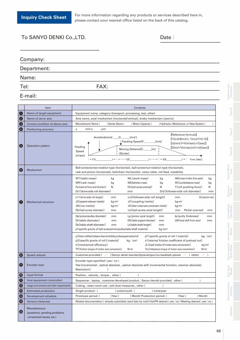
66
Fe
atu
res a
nd
Fu
ncti
on
sT
yp
e R
Ty
pe P
Ty
pe M
Ha
rmo
nic
Ge
ar
Mo
de
lT
yp
e R
Mu
lti-
Ax
isE
lectr
om
ag
ne
tic
Bra
ke
Mo
de
lS
pu
r G
ea
r M
od
el
Sta
nd
ard
M
od
el
Mo
tor
Dim
en
sio
na
l D
raw
ing
s
Lo
w-b
ackla
sh
G
ear
Mo
del
Op
tio
ns
➊ Name of target equipment Equipment name, category (transport, processing, test, other)
❾ Encoder type
Encoder type specified ( yes / no )
Yes:(incremental , optical absolute , optical absolute with incremental function, resolver absolute)
Resolution( )
➋ Name of servo axis Axis name, axial mechanism (horizontal/vertical), brake mechanism (yes/no)
➌ Current condition of above axis Manufacturer Name ( ) Series Name ( ) Motor Capacity ( ) Hydraulic, Mechanical, or New System ( )
➍ Positioning accuracy ± mm・± μm
➎ Operation pattern
Accelerationα:__G・___[m/s2]
Feeding SpeedV:____[m/s]
Feeding
Speed
[m/sec]
【Reference formula】【1G=9.8[m/s2], 1[m/s2]≒0.1G】【α[m/s2]=V[m/sec]÷t1[sec]】【D[m]=V[m/sec]×(t1+t2)[sec]】
Moving DistanceD:___[m]
(Stroke)
➏ MechanismBall-screw/screw-rotation type (horizontal), ball-screw/nut-rotation type (horizontal),
rack and pinion (horizontal), belt/chain (horizontal), rotary table, roll feed, instability
➐ Mechanical structure
WT(table mass) kg WL(work mass) kg WA(mass of other drive parts) kg
WR(rack mass) kg WB(belt/chain mass) kg WC(counterbalance mass) kg
Fa(external force axial direction) N Fb(ball-screw preload) N T(roll pushing force) N
Dr1(drive-side roll diameter) mm Dr2(follower-side roll diameter) mm
Lr1(drive-side roll length) mm Lr2(follower-side roll length) mm G(reduction ratio)JG(speed-reducer inertia) kg・m2 JC(coupling inertia) kg・m2
JN(nut inertia) kg・m2 JO(other motor-axis conversion inertia) kg・m2
Db(ball-screw diameter) mm Lb(ball-screw axial length) mm Pb(ball -screw lead) mm
Dp(pinion/pulley diameter) mm Lp(pinion axial length) mm tp(pully thickness) mm
Dt(table diameter) mm Dh(table-support dianeter) mm LW(load shift from axis) mm
Ds(table shaft diameter) mm Ls(table shaft length) mm
ρ(specific gravity of ball-screw/pinion/pulley/table-shaft material) kg・cm3
μ(friction coefficient between sheet and shiliding-surface/support-section/roll) ρ1(specific gravity of roll-1 material) kg/cm3
ρ2(specific gravity of roll-2 material) kg/cm3 κ(internal friction coefficient of preload nut)η(mechanical efficiency) JL(load inertia of motor-axis conversion) kg・m2
TF(friction torque of motor axis conversion) N・m Tu(imbalance torque of motor axis conversion) N・m
❿ Input format Position , velocity , torque , other ( )
⓫ Host equipment (controller) Sequencer , laptop , customer-developed product , Sanyo dennki-provided , other ( )
⓭ Estimated production Single product: ( ) units/mouth ( ) units/year
⓮ Development schedule Prototype period: ( ) Year ( ) Month Production period: ( ) Year ( ) Month
Various measures Related documentation ( already submitted; send later by mail) Visit/PR desired ( yes / no ) Meeting desired ( yes / no )⓯
⓰Miscellaneous
(questions, pending problems,
unresolved issues, etc.)
⓬ Usage environment and other requirements Cutting , clean-room use , anti-dust measures , other ( )
➑ Speed reducer Customer-provided ( / )・Sanyo denki standard(planet/spur/no-backlash-planet / ) other( / )
Item Contents
Time
Inquiry Check SheetFor more information regarding any products or services described here in,
please contact your nearest office listed on the back of this catalog.
Date:To SANYO DENKI Co.,LTD.
Company:
Department:
Name:
Tel: FAX:
E-mail:

http://www.sanyodenki.com
*For any question or inquiry regarding the above, contact our Sales Department.
Cautions
■ Precautions For Adoption
Failure to follow the precautions on the right may cause moderate injury and property damage, or in some circumstances,could lead to a serious accident. Always follow all listed precautions.
468 Amapola Avenue Torrance, CA 90501, U.S.A.
3-33-1, Minami-Otsuka, Toshima-ku, Tokyo, 170-8451, Japan
P.A. Paris Nord Ⅱ, 48 Allée des Erables-VILLEPINTE, BP.57286, F-95958 ROISSY CDG Cedex, France
Frankfurter Strasse 92, 65760 Eschborn, Germany
10, Hoe Chiang Road, #14-03A/04, Keppel Towers, Singapore 089315
Room 2106-2109, Bldg A, Far East International Plaza, No.319, Xianxia Road, Shanghai, 200051, China
Room 1208, 12F, No.96 Chung Shan N, Road, Sec.2, Taipei 104, Taiwan, R.O.C.
Room 2305, 23/F, South Tower, Concordia Plaza, 1 Science Museum Road, TST East, Kowloon, Hong Kong
9F 5-2, Sunwha-dong Jung-gu Seoul, 100-130, Korea
TEL: +81 3 5927 1020
TEL: +49 6196 76113 0
TEL: +82 2 773 5623
TEL: +86 21 6235 1107
TEL: +1 310 783 5400
TEL: +33 1 48 63 26 61
TEL: +886 2 2511 3938
TEL: +852 2312 6250
TEL: +65 6223 1071
CATALOG NO. S0838B010 ’14.5.IT