Embed Size (px)
Citation preview
Closed-Loop Shape Control of a Haptic Jamming Deformable Surface
Andrew A. Stanley1, Kenji Hata2, and Allison M. Okamura1
Abstract— A Haptic Jamming tactile display, consisting of anarray of thin particle jamming cells, can change its shape andmechanical properties simultaneously through a combinationof vacuuming individual cells, pressurizing the air chamberbeneath the surface, and pinning the nodes between the cellsat various heights. In previous particle jamming devices forhaptics and soft robotics, shape has typically been commandedopen-loop or manipulated directly by a human user. A newalgorithm was designed for the three types of actuation inputsfor a Haptic Jamming surface, using the depth map provided byan RGB-D sensor as shape feedback for closed-loop control tomatch a desired surface input. To test the closed-loop controlaccuracy of the system, a mass-spring model of the HapticJamming device generated three unique surface shapes asdesired inputs into the controller with a mean height rangeof 25.1 mm. The average correlation coefficient between thedesired input shape and the experimental output generated bythe controller on the actual device across four trials for eachshape was 0.88, with an average height error of 2.7 mm. Whenthe desired input surface is generated from a 3D model of anobject that a Haptic Jamming surface cannot necessarily re-create, the difference between the input and the output increasessubstantially. However, simulation of a larger array suggeststhat a Haptic Jamming surface can provide a compelling matchfor these more complicated shapes.
I. INTRODUCTION
Haptic interfaces add a richness to human-computer orhuman-robot interaction not experienced by purely visual orauditory interfaces. Traditional haptic interfaces that consistof robotic linkages or tactile actuators can render forces or vi-brations from a virtual, remote, or teleoperated environmentto the user through a single point of contact. However, shapechanging interfaces promise a more immersive experience byallowing multi-point contact in which the user can use hisor her entire hands. For applications ranging from medicalsimulation to product design, the natural use of the entirehand for haptic exploration enables a more natural form ofinteraction through the sense of touch. The Haptic Jammingconcept [1] in particular presents a promising form of suchan encountered-type interface, as the combination of particlejamming and pneumatics allows for simultaneous controlof mechanical properties and deformable shape across acontinuous surface. Separate vacuum lines run to each cell ina multi-cell Haptic Jamming device to allow varied rigidity in
*This work was supported in part by U.S. Army Medical Research andMateriel Command (USAMRMC; W81XWH-11-C-0091), the National Sci-ence Foundation (NSF; 1217635), and by the National Science FoundationGraduate Research Fellowship Program.
1A. A. Stanley and A. M. Okamura are with the Department ofMechanical Engineering, Stanford University, Stanford, CA 94305 [email protected], [email protected]
2K. Hata is with the Department of Computer Science, Stanford Univer-sity, Stanford, CA 94305 USA. [email protected]
150
All Axes in mm00
100
30
0
150
00
100
0
30
Fig. 1. A user interacts with a 12-cell Haptic Jamming surface (top) after ithas reconfigured to match a desired surface (bottom left) using an overheaddepth sensor for shape feedback (bottom right). Cells become darker astheir density increases when they are jammed, making them more rigidto the touch as well as allowing them to hold the shape of their currentconfiguration.
each region of the surface. In this interface, particle jammingof individual cells in the array serves not only to adjustthe mechanical stiffness that the user feels but also as ameans to control shape. When positive pressure is appliedto the air chamber below, soft cells balloon outward whilerigid cells maintain their current curvature, and pinning thenodes between cells allows greater shape output variability.This methodology was originally developed for simulation ofmedical procedures that require direct exploration with thebare hand to make a diagnosis. For these scenarios, a HapticJamming device can display tissue properties ranging fromsoft to hard in any region of its surface and in a variety ofform factors.
While previous research around Haptic Jamming focusedlargely on device design [1], including some basic open-loop control for shape outputs and controlling the mechanicalproperties across the surface [2], this work demonstrates thefirst closed-loop control of the output shape. The followingsection of this paper discusses prior work in the fields of softrobotics, particle jamming, and shape changing interfaces.Section III describes the setup of the system we use todemonstrate closed-loop control on a 12-cell prototype, in-cluding mechanical design improvements, additional systemcomponents, and an improved method for regulating the
air pressure inside the chamber beneath the surface of thedevice. Section IV outlines the methods and algorithms wedeveloped to control the shape of the device, which we thenevaluate with both quantitative and qualitative metrics inSection V before concluding and discussing future work inSection VI.
II. BACKGROUNDThe Haptic Jamming interface builds upon prior work
in various fields ranging from soft robotics and particlejamming to shape changing interfaces. We discuss some ofthe most relevant previous research here.
A. Soft Robotics and Particle JammingThe recent emergence of flexible and compliant actuation
and sensing techniques has sparked extensive innovation inthe field of soft robotics. In particular, soft robotics hasgreatly advanced biologically inspired robots by allowingdeformable elements with much greater maximum strainwhile reducing the weight of the embedded actuators [3].Particle jamming greatly increases the control over themechanical properties of an object. These features have ledto the development of a sphere for robotic locomotion [4],novel robotic manipulators [5], universal end effectors [6], aflexible endoscope with controllable rigidity [7], novel userinterfaces [8] [9] [10], and a wearable force display [11].For the majority of these systems, either the user controlsthe deformation of the particle jamming components or theexact shape is not a critical aspect of the functionality. Forthose that do rely on computer-controlled deformations, likethe locomotive sphere and robotic manipulator, such controlis conducted open-loop.
B. Shape Changing InterfacesAn idealized form of 3D user interface for input into
and output from a computer would be a tactile display ordeformable object that can change shape under the controlof both the user and the computer with both precise actu-ation and sensing, conceptualized as “Digital Clay” [12].Implementations of such displays often fall under either a“bed of nails” or “deformable crust” approach, althoughHaptic Jamming partially hybridizes the two with its arrayof pinnable nodes and jamming cells and compliant surface.The actuators in the “bed of nails” can range from shapememory alloys [13] and pneumatics [14] [15] to motor-drivenlinear actuators [16], so the shape control consists primarilyof down-sampling the desired input shape to the resolutionof the array and positioning each element accordingly. Thus,the number of actuators scales quadratically as the size of thearray grows, but one implementation with hydraulic actuatorsarranged along the rows and columns of the array [17]allows the number of actuators to scale linearly with in-creased resolution with a controller based on singular valuedecomposition [18]. “Deformable crust” implementations,like the SmartMesh multi-loop mechanism [19] and theFormable Object [20], rely on extendable links arranged in adouble-layer square grid and kinematics optimized to rendercylinders or spheres.
P
PSolenoid PlungerRetracted
Solenoid PlungerEngaged
Reel Reel Cap
Inlet for Pressurized Air Silicone
Top LayerSiliconeBottom Layer
Tubing forVacuum Lines
EmbeddedBinding Post
for NodePinning
Coffee Grounds
Kinect -1 meterabovesurface
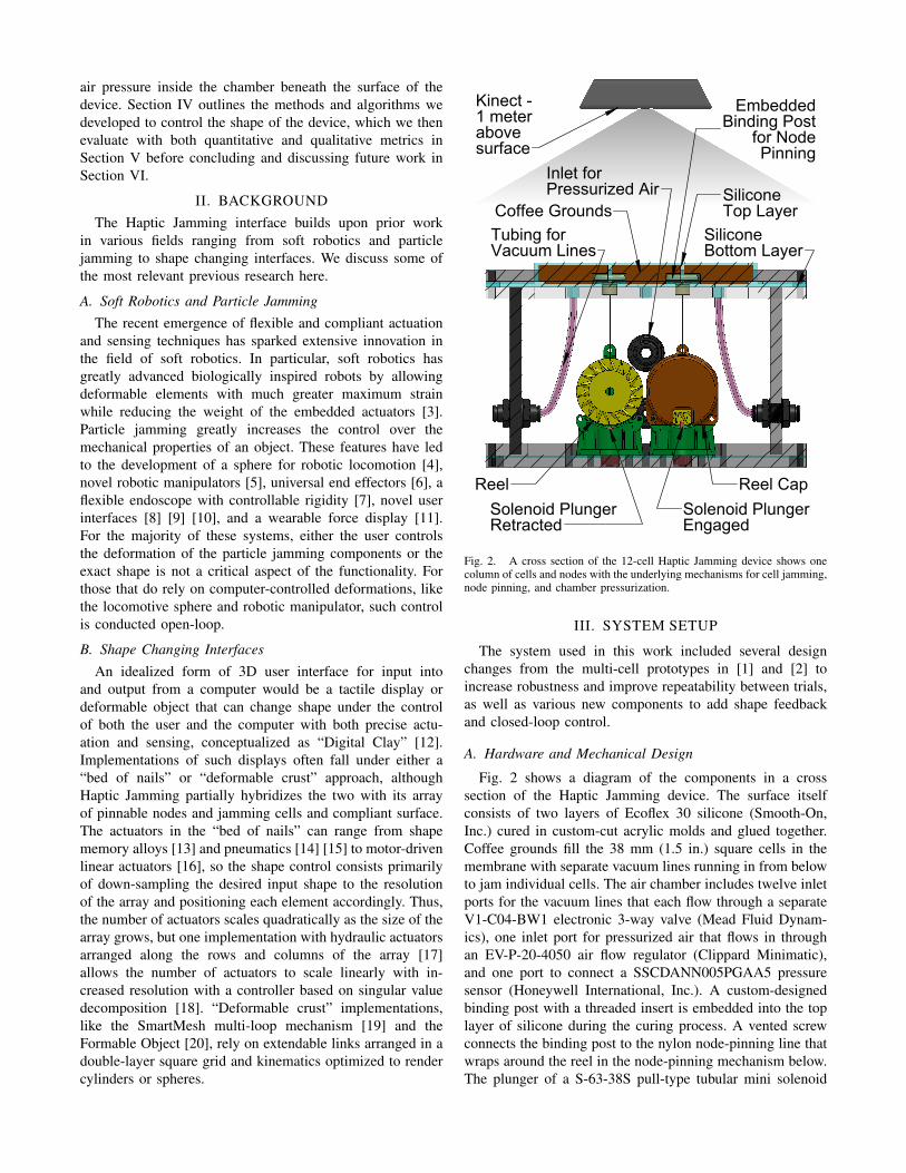
Fig. 2. A cross section of the 12-cell Haptic Jamming device shows onecolumn of cells and nodes with the underlying mechanisms for cell jamming,node pinning, and chamber pressurization.
III. SYSTEM SETUP
The system used in this work included several designchanges from the multi-cell prototypes in [1] and [2] toincrease robustness and improve repeatability between trials,as well as various new components to add shape feedbackand closed-loop control.
A. Hardware and Mechanical Design
Fig. 2 shows a diagram of the components in a crosssection of the Haptic Jamming device. The surface itselfconsists of two layers of Ecoflex 30 silicone (Smooth-On,Inc.) cured in custom-cut acrylic molds and glued together.Coffee grounds fill the 38 mm (1.5 in.) square cells in themembrane with separate vacuum lines running in from belowto jam individual cells. The air chamber includes twelve inletports for the vacuum lines that each flow through a separateV1-C04-BW1 electronic 3-way valve (Mead Fluid Dynam-ics), one inlet port for pressurized air that flows in throughan EV-P-20-4050 air flow regulator (Clippard Minimatic),and one port to connect a SSCDANN005PGAA5 pressuresensor (Honeywell International, Inc.). A custom-designedbinding post with a threaded insert is embedded into the toplayer of silicone during the curing process. A vented screwconnects the binding post to the nylon node-pinning line thatwraps around the reel in the node-pinning mechanism below.The plunger of a S-63-38S pull-type tubular mini solenoid

Desired Shape Input
Calculate Node
Heights and Cell
Curvatures
ndes ,
κdes
Haptic Jamming
Actuation Algorithm
nest ,
κest
Device
Dynamics
Device Shape Output
jam cells
pin nodesδn ,
δκ
air pressure setting
Kinect Depth Sensor
Depth Image
PID
Controller
δP air
flow
rate
Chamber
Dynamics
chamber
air
pressure
Pressure
Sensor
measured air pressure
PWM
signal
Flow
Regulator
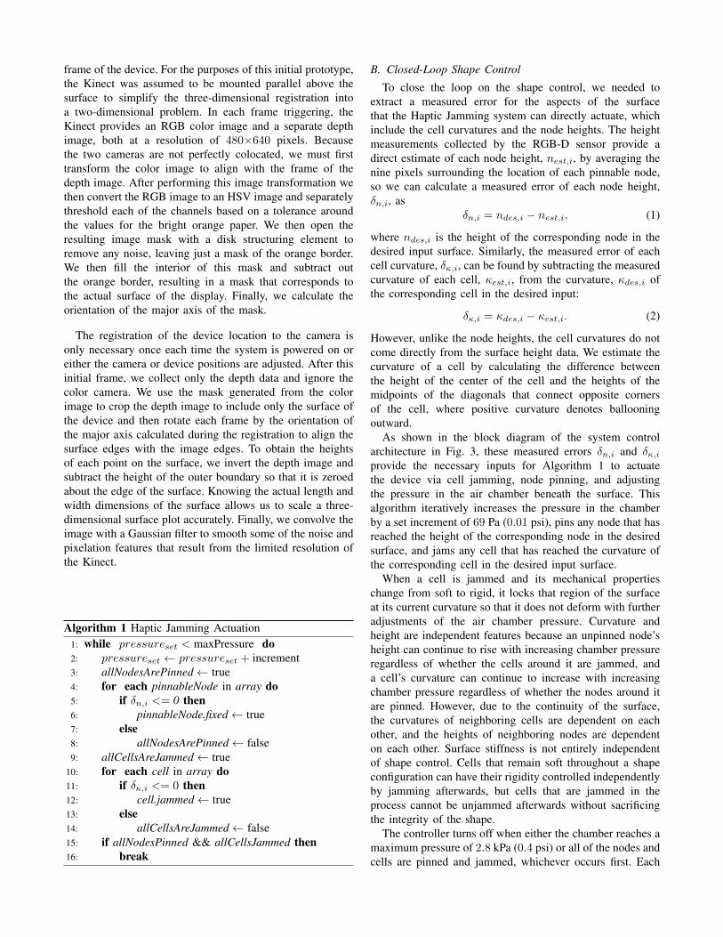
Fig. 3. A block diagram of the system control architecture. The outer loop runs once per iteration of Algorithm 1 while the inner pressure control loop,highlighted in yellow, runs continuously.
(ElectroMechanicsOnline) extends into the teeth of the reelto lock it in place or retracts to allow it to spin freely when anincrease in chamber pressure balloons the surface outward.A torsional spring in the reel winds up the line when theair pressure is released and the surface is unjammed. Thetooth count on the ratchet and the diameter of the sectionof the reel around which the nylon line wraps result in aheight resolution of 4.7 mm per tooth. While this limits theresolution of the shape display, the mechanism allows the useof a low-power actuator that performs no direct work on thesystem; rather, the passive mechanical components performthe work. A Kinect for XBox 360 (Microsoft Corporation)mounts one meter above the surface, the minimum distancethat its depth sensor can measure. At this distance, each pixelof the connect covers about 2 mm by 2 mm of the surfacewith a depth resolution around 3.5 mm [21]. The ratchetingmethod can result in the Haptic Jamming surface deformingabove the desired surface height, and the noise and limitedresolution of the Kinect estimation can result in a deviceoutput with errors on either side of the desired surface height.
B. Electronics and Data Acquisition
The 12-cell prototype requires 19 total actuators, including12 valves for the vacuum lines, 6 solenoids to pin the nodes,and a flow regulator to control the air chamber pressure. Inorder to control all 18 of these valve and solenoid actuatorssimultaneously from three digital output lines of a USB X-Series 6343 DAQ (National Instruments), we use a daisychain of 74HC595 shift registers. The output lines of theshift registers connect to the inputs of ULN2803 Darlingtonarray transistors that power the actuators in low side drivefrom a 24V power supply. The flow regulator is controlledby sending a pulse width modulation output from the DAQthrough another input to one of the Darlington arrays toget a 0-24V analog signal. The 0-5V analog output of thepressure sensor connects directly to an analog input of theDAQ. The camera data from the Kinect is read into Matlab
using the Image Acquisition Toolbox and analyzed with theImage Processing toolbox.
C. Pressure Control
To maintain smooth pressure control inside the air cham-ber beneath the surface, we implemented a PID controlleron the flow rate of air into the chamber with a pressuresensor attached directly to the chamber to provide feedback,as shown in the inner loop of the full system’s controller inFig. 3. This setup has two main advantages over the commer-cial pressure regulators used in previous prototypes, whichtypically implement a bang-bang (hysteresis) controller witha pair of solenoid valves based on feedback from a pressuresensor on the outlet of the regulator. First, the derivativecontroller smooths out the popping sensation felt by theuser when a bang-bang controller regulates the pressure,because when a user presses on the surface it cause smallpressure changes inside the box, requiring adjustments bythe regulator. Second, the integral controller has the addedbenefit of negating the effects of any small leaks in the boxwithout sacrificing smoothness in the pressure control. Acommercial regulator maintains the pressure on its outlet,which does not match the pressure inside the box if thereare any leaks.
IV. SHAPE SENSING AND CONTROLPrevious implementations of Haptic Jamming surfaces did
not include any means for shape sensing, and thus relied onpreprogrammed sequences of operations to create a desiredshape. This limited both the complexity and accuracy ofshapes that the device could create. Adding a sensor intothe loop allows feedback of the output shape to expand thecapabilities of the device.
A. Depth Sensor Registration to Surface Heights
As shown in Fig. 1, we lined the outside of the HapticJamming surface with a bright orange border to facilitateregistration of the Kinect’s RGB-D sensor to the coordinate
frame of the device. For the purposes of this initial prototype,the Kinect was assumed to be mounted parallel above thesurface to simplify the three-dimensional registration intoa two-dimensional problem. In each frame triggering, theKinect provides an RGB color image and a separate depthimage, both at a resolution of 480×640 pixels. Becausethe two cameras are not perfectly colocated, we must firsttransform the color image to align with the frame of thedepth image. After performing this image transformation wethen convert the RGB image to an HSV image and separatelythreshold each of the channels based on a tolerance aroundthe values for the bright orange paper. We then open theresulting image mask with a disk structuring element toremove any noise, leaving just a mask of the orange border.We then fill the interior of this mask and subtract outthe orange border, resulting in a mask that corresponds tothe actual surface of the display. Finally, we calculate theorientation of the major axis of the mask.
The registration of the device location to the camera isonly necessary once each time the system is powered on oreither the camera or device positions are adjusted. After thisinitial frame, we collect only the depth data and ignore thecolor camera. We use the mask generated from the colorimage to crop the depth image to include only the surface ofthe device and then rotate each frame by the orientation ofthe major axis calculated during the registration to align thesurface edges with the image edges. To obtain the heightsof each point on the surface, we invert the depth image andsubtract the height of the outer boundary so that it is zeroedabout the edge of the surface. Knowing the actual length andwidth dimensions of the surface allows us to scale a three-dimensional surface plot accurately. Finally, we convolve theimage with a Gaussian filter to smooth some of the noise andpixelation features that result from the limited resolution ofthe Kinect.
Algorithm 1 Haptic Jamming Actuation1: while pressureset < maxPressure do2: pressureset ← pressureset + increment3: allNodesArePinned← true4: for each pinnableNode in array do5: if δn,i <= 0 then6: pinnableNode.fixed← true7: else8: allNodesArePinned← false9: allCellsAreJammed← true
10: for each cell in array do11: if δκ,i <= 0 then12: cell.jammed← true13: else14: allCellsAreJammed← false15: if allNodesPinned && allCellsJammed then16: break
B. Closed-Loop Shape Control
To close the loop on the shape control, we needed toextract a measured error for the aspects of the surfacethat the Haptic Jamming system can directly actuate, whichinclude the cell curvatures and the node heights. The heightmeasurements collected by the RGB-D sensor provide adirect estimate of each node height, nest,i, by averaging thenine pixels surrounding the location of each pinnable node,so we can calculate a measured error of each node height,δn,i, as
δn,i = ndes,i − nest,i, (1)
where ndes,i is the height of the corresponding node in thedesired input surface. Similarly, the measured error of eachcell curvature, δκ,i, can be found by subtracting the measuredcurvature of each cell, κest,i, from the curvature, κdes,i ofthe corresponding cell in the desired input:
δκ,i = κdes,i − κest,i. (2)
However, unlike the node heights, the cell curvatures do notcome directly from the surface height data. We estimate thecurvature of a cell by calculating the difference betweenthe height of the center of the cell and the heights of themidpoints of the diagonals that connect opposite cornersof the cell, where positive curvature denotes ballooningoutward.
As shown in the block diagram of the system controlarchitecture in Fig. 3, these measured errors δn,i and δκ,iprovide the necessary inputs for Algorithm 1 to actuatethe device via cell jamming, node pinning, and adjustingthe pressure in the air chamber beneath the surface. Thisalgorithm iteratively increases the pressure in the chamberby a set increment of 69 Pa (0.01 psi), pins any node that hasreached the height of the corresponding node in the desiredsurface, and jams any cell that has reached the curvature ofthe corresponding cell in the desired input surface.
When a cell is jammed and its mechanical propertieschange from soft to rigid, it locks that region of the surfaceat its current curvature so that it does not deform with furtheradjustments of the air chamber pressure. Curvature andheight are independent features because an unpinned node’sheight can continue to rise with increasing chamber pressureregardless of whether the cells around it are jammed, anda cell’s curvature can continue to increase with increasingchamber pressure regardless of whether the nodes around itare pinned. However, due to the continuity of the surface,the curvatures of neighboring cells are dependent on eachother, and the heights of neighboring nodes are dependenton each other. Surface stiffness is not entirely independentof shape control. Cells that remain soft throughout a shapeconfiguration can have their rigidity controlled independentlyby jamming afterwards, but cells that are jammed in theprocess cannot be unjammed afterwards without sacrificingthe integrity of the shape.
The controller turns off when either the chamber reaches amaximum pressure of 2.8 kPa (0.4 psi) or all of the nodes andcells are pinned and jammed, whichever occurs first. Each
150
All Axes in mm
100
50
00
20
Shape A
40
60
80
100
0
10
20
30
150
All Axes in mm
100
50
00
20
Shape B
40
60
80
100
30
20
10
0
150
All Axes in mm
100
50
00
20
40
60
80
100
0
10
20
30
150
All Axes in mm
100
50
00
20
40
60
80
100
0
10
20
30
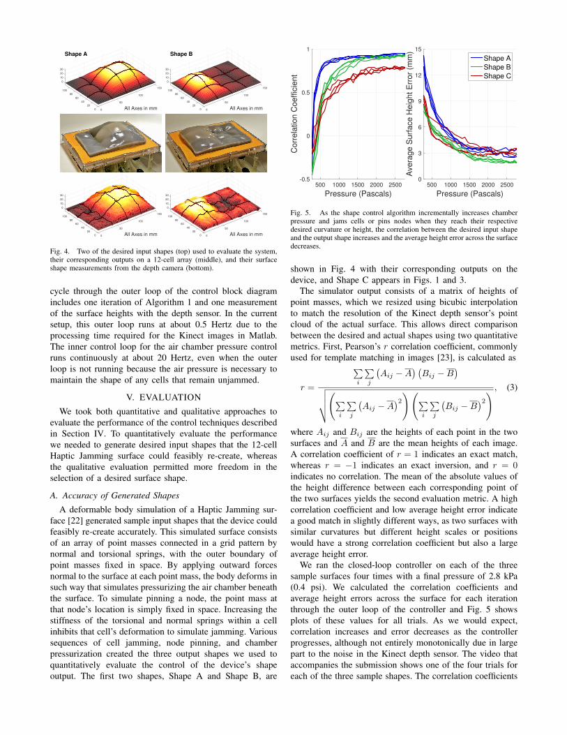
Fig. 4. Two of the desired input shapes (top) used to evaluate the system,their corresponding outputs on a 12-cell array (middle), and their surfaceshape measurements from the depth camera (bottom).
cycle through the outer loop of the control block diagramincludes one iteration of Algorithm 1 and one measurementof the surface heights with the depth sensor. In the currentsetup, this outer loop runs at about 0.5 Hertz due to theprocessing time required for the Kinect images in Matlab.The inner control loop for the air chamber pressure controlruns continuously at about 20 Hertz, even when the outerloop is not running because the air pressure is necessary tomaintain the shape of any cells that remain unjammed.
V. EVALUATION
We took both quantitative and qualitative approaches toevaluate the performance of the control techniques describedin Section IV. To quantitatively evaluate the performancewe needed to generate desired input shapes that the 12-cellHaptic Jamming surface could feasibly re-create, whereasthe qualitative evaluation permitted more freedom in theselection of a desired surface shape.
A. Accuracy of Generated Shapes
A deformable body simulation of a Haptic Jamming sur-face [22] generated sample input shapes that the device couldfeasibly re-create accurately. This simulated surface consistsof an array of point masses connected in a grid pattern bynormal and torsional springs, with the outer boundary ofpoint masses fixed in space. By applying outward forcesnormal to the surface at each point mass, the body deforms insuch way that simulates pressurizing the air chamber beneaththe surface. To simulate pinning a node, the point mass atthat node’s location is simply fixed in space. Increasing thestiffness of the torsional and normal springs within a cellinhibits that cell’s deformation to simulate jamming. Varioussequences of cell jamming, node pinning, and chamberpressurization created the three output shapes we used toquantitatively evaluate the control of the device’s shapeoutput. The first two shapes, Shape A and Shape B, are
Pressure (Pascals)
500 1000 1500 2000 2500
Co
rre
latio
n C
oe
ffic
ien
t
-0.5
0
0.5
1
Pressure (Pascals)
500 1000 1500 2000 2500
Ave
rag
e S
urf
ace
He
igh
t E
rro
r (m
m)
0
3
6
9
12
15
Shape A
Shape B
Shape C
Fig. 5. As the shape control algorithm incrementally increases chamberpressure and jams cells or pins nodes when they reach their respectivedesired curvature or height, the correlation between the desired input shapeand the output shape increases and the average height error across the surfacedecreases.
shown in Fig. 4 with their corresponding outputs on thedevice, and Shape C appears in Figs. 1 and 3.
The simulator output consists of a matrix of heights ofpoint masses, which we resized using bicubic interpolationto match the resolution of the Kinect depth sensor’s pointcloud of the actual surface. This allows direct comparisonbetween the desired and actual shapes using two quantitativemetrics. First, Pearson’s r correlation coefficient, commonlyused for template matching in images [23], is calculated as
r =
∑i
∑j
(Aij −A
) (Bij −B
)√√√√(∑
i
∑j
(Aij −A
)2)(∑i
∑j
(Bij −B
)2) , (3)
where Aij and Bij are the heights of each point in the twosurfaces and A and B are the mean heights of each image.A correlation coefficient of r = 1 indicates an exact match,whereas r = −1 indicates an exact inversion, and r = 0indicates no correlation. The mean of the absolute values ofthe height difference between each corresponding point ofthe two surfaces yields the second evaluation metric. A highcorrelation coefficient and low average height error indicatea good match in slightly different ways, as two surfaces withsimilar curvatures but different height scales or positionswould have a strong correlation coefficient but also a largeaverage height error.
We ran the closed-loop controller on each of the threesample surfaces four times with a final pressure of 2.8 kPa(0.4 psi). We calculated the correlation coefficients andaverage height errors across the surface for each iterationthrough the outer loop of the controller and Fig. 5 showsplots of these values for all trials. As we would expect,correlation increases and error decreases as the controllerprogresses, although not entirely monotonically due in largepart to the noise in the Kinect depth sensor. The video thataccompanies the submission shows one of the four trials foreach of the three sample shapes. The correlation coefficients
level off at mean values of 0.94, 0.93, and 0.78 for ShapesA, B, and C, respectively. The heights within each desiredsurface had ranges of 32.3 mm, 23.1 mm, and 22.4 mm, withcorresponding average height errors of 3.1 mm, 1.9 mm, and3.2 mm from the output surface.
B. Re-creating 3D Objects
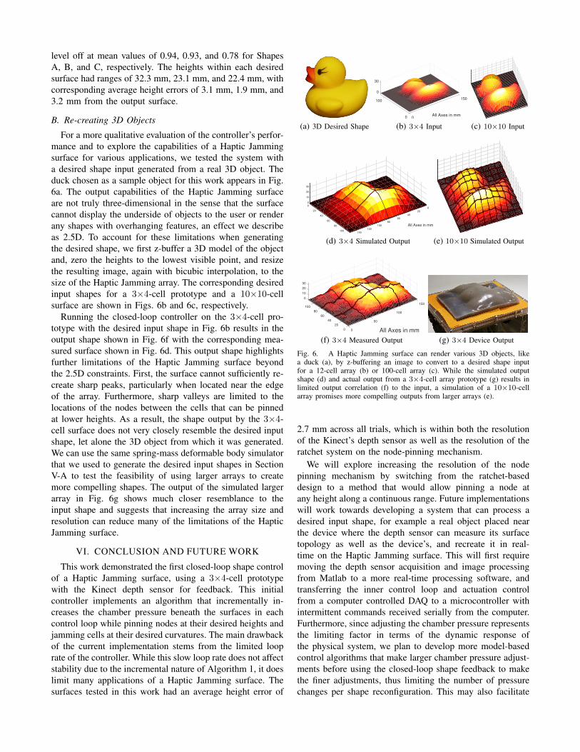
For a more qualitative evaluation of the controller’s perfor-mance and to explore the capabilities of a Haptic Jammingsurface for various applications, we tested the system witha desired shape input generated from a real 3D object. Theduck chosen as a sample object for this work appears in Fig.6a. The output capabilities of the Haptic Jamming surfaceare not truly three-dimensional in the sense that the surfacecannot display the underside of objects to the user or renderany shapes with overhanging features, an effect we describeas 2.5D. To account for these limitations when generatingthe desired shape, we first z-buffer a 3D model of the objectand, zero the heights to the lowest visible point, and resizethe resulting image, again with bicubic interpolation, to thesize of the Haptic Jamming array. The corresponding desiredinput shapes for a 3×4-cell prototype and a 10×10-cellsurface are shown in Figs. 6b and 6c, respectively.
Running the closed-loop controller on the 3×4-cell pro-totype with the desired input shape in Fig. 6b results in theoutput shape shown in Fig. 6f with the corresponding mea-sured surface shown in Fig. 6d. This output shape highlightsfurther limitations of the Haptic Jamming surface beyondthe 2.5D constraints. First, the surface cannot sufficiently re-create sharp peaks, particularly when located near the edgeof the array. Furthermore, sharp valleys are limited to thelocations of the nodes between the cells that can be pinnedat lower heights. As a result, the shape output by the 3×4-cell surface does not very closely resemble the desired inputshape, let alone the 3D object from which it was generated.We can use the same spring-mass deformable body simulatorthat we used to generate the desired input shapes in SectionV-A to test the feasibility of using larger arrays to createmore compelling shapes. The output of the simulated largerarray in Fig. 6g shows much closer resemblance to theinput shape and suggests that increasing the array size andresolution can reduce many of the limitations of the HapticJamming surface.
VI. CONCLUSION AND FUTURE WORK
This work demonstrated the first closed-loop shape controlof a Haptic Jamming surface, using a 3×4-cell prototypewith the Kinect depth sensor for feedback. This initialcontroller implements an algorithm that incrementally in-creases the chamber pressure beneath the surfaces in eachcontrol loop while pinning nodes at their desired heights andjamming cells at their desired curvatures. The main drawbackof the current implementation stems from the limited looprate of the controller. While this slow loop rate does not affectstability due to the incremental nature of Algorithm 1, it doeslimit many applications of a Haptic Jamming surface. Thesurfaces tested in this work had an average height error of
(a) 3D Desired Shape
150
All Axes in mm00
100
30
0
(b) 3×4 Input (c) 10×10 Input
All Axes in mm
0
20
40
60
80
100
120
140100
80
60
40
20
30
20
10
0
0
(d) 3×4 Simulated Output (e) 10×10 Simulated Output
150
All Axes in mm
100
50
00
20
40
60
80
100
10
0
30
20
(f) 3×4 Measured Output (g) 3×4 Device Output
Fig. 6. A Haptic Jamming surface can render various 3D objects, likea duck (a), by z-buffering an image to convert to a desired shape inputfor a 12-cell array (b) or 100-cell array (c). While the simulated outputshape (d) and actual output from a 3×4-cell array prototype (g) results inlimited output correlation (f) to the input, a simulation of a 10×10-cellarray promises more compelling outputs from larger arrays (e).
2.7 mm across all trials, which is within both the resolutionof the Kinect’s depth sensor as well as the resolution of theratchet system on the node-pinning mechanism.
We will explore increasing the resolution of the nodepinning mechanism by switching from the ratchet-baseddesign to a method that would allow pinning a node atany height along a continuous range. Future implementationswill work towards developing a system that can process adesired input shape, for example a real object placed nearthe device where the depth sensor can measure its surfacetopology as well as the device’s, and recreate it in real-time on the Haptic Jamming surface. This will first requiremoving the depth sensor acquisition and image processingfrom Matlab to a more real-time processing software, andtransferring the inner control loop and actuation controlfrom a computer controlled DAQ to a microcontroller withintermittent commands received serially from the computer.Furthermore, since adjusting the chamber pressure representsthe limiting factor in terms of the dynamic response ofthe physical system, we plan to develop more model-basedcontrol algorithms that make larger chamber pressure adjust-ments before using the closed-loop shape feedback to makethe finer adjustments, thus limiting the number of pressurechanges per shape reconfiguration. This may also facilitate
transferring directly from one shape to another withoutrequiring returning to a flat, depressurized, and unjammedstate as an intermediate step.
To validate that a larger array can create more compellingoutput shapes as suggested by the simulation output in Fig.6g, we are constructing a 100-cell array. This will not onlyserve as a test bed for the more advanced control algorithmswe plan to develop but also for a variety of interactionfeatures, expanding those explored with the pin array ofthe inFORM interface like object manipulation and telepres-ence [16] to similar features on the continuous, deformablesurface of a Haptic Jamming interface. In addition, we planto embed flexible capacitive sensors into the silicone layersof the surface, which could simultaneously provide shapefeedback for the controller without the concerns of occlusionfrom user interaction as well as touch or proximity feedbackto enable a greater variety of user interaction features.
REFERENCES
[1] A. A. Stanley, J. C. Gwilliam, and A. M. Okamura, “Haptic jamming:A deformable geometry, variable stiffness tactile display using pneu-matics and particle jamming,” in IEEE World Haptics Conference,pp. 25–30, 2013.
[2] A. A. Stanley and A. M. Okamura, “Controllable surface haptics viaparticle jamming and pneumatics,” IEEE Transactions on Haptics,vol. 8, no. 1, pp. 20–30, 2015.
[3] D. Trivedi, C. D. Rahn, W. M. Kier, and I. D. Walker, “Soft robotics:Biological inspiration, state of the art, and future research,” AppliedBionics and Biomechanics, vol. 5, no. 3, pp. 99–117, 2008.
[4] E. Steltz, A. Mozeika, N. Rodenberg, E. Brown, and H. Jaeger, “JSEL:Jamming Skin Enabled Locomotion,” in IEEE/RSJ International Con-ference on Intelligent Robots and Systems, pp. 5672–5677, 2009.
[5] N. G. Cheng, M. B. Lobovsky, S. J. Keating, A. M. Setapen, K. I. Gero,A. E. Hosoi, and K. D. Iagnemma, “Design and Analysis of a Robust,Low-cost, Highly Articulated manipulator enabled by jamming ofgranular media,” in IEEE International Conference on Robotics andAutomation, pp. 4328–4333, 2012.
[6] E. Brown, N. Rodenberg, J. Amend, A. Mozeika, E. Steltz, M. R.Zakin, H. Lipson, and H. M. Jaeger, “Universal robotic gripper basedon the jamming of granular material,” Proceedings of the NationalAcademy of Sciences, vol. 107, no. 44, pp. 18809–18814, 2010.
[7] A. Loeve and O. van de Ven, “Vacuum packed particles as flexibleendoscope guides with controllable rigidity,” Granular Matter, vol. 12,pp. 543–554, 2010.
[8] S. Follmer, D. Leithinger, A. Olwal, N. Cheng, and H. Ishii, “JammingUser Interfaces: Programmable Particle Stiffness and Sensing forMalleable and Shape-Changing Devices,” in ACM Symposium on UserInterface Software and Technology, pp. 519–528, 2012.
[9] A. Mazzone, C. Spagno, and A. Kunz, “The HoverMesh: A deformablestructure based on vacuum cells,” in Proc. ACM SIGCHI InternationalConference on Advances in Computer Entertainment Technology,pp. 187–193, 2004.
[10] N. Aihara, T. Sato, and H. Koike, “Highly deformable interactive 3Dsurface display,” in ACM Symposium on User Interface Software andTechnology, p. 91, 2012.
[11] T. Mitsuda, S. Kuge, M. Wakabayashi, and S. Kawamura, “WearableForce Display Using a Particle Mechanical Constraint,” Presence:Teleoperators and Virtual Environments, vol. 11, no. 6, pp. 569–577,2002.
[12] J. Rossignac, M. Allen, W. Book, A. Glezer, I. Ebert-Uphoff, C. Shaw,D. Rosen, S. Askins, P. Bosscher, J. Gargus, I. Llamas, and A. Nguyen,“Finger sculpting with Digital Clay: 3D shape input and output througha computer-controlled real surface,” in Shape Modeling International,pp. 229–231, 2003.
[13] P. Taylor, A. Moser, and A. Creed, “A sixty-four element tactile displayusing shape memory alloy wires,” Displays, vol. 18, pp. 163–168,1998.
[14] C.-H. King, M. O. Culjat, M. L. Franco, J. W. Bisley, E. Dutson,and W. S. Grundfest, “Optimization of a pneumatic balloon tactiledisplay for robot-assisted surgery based on human perception.,” IEEETransactions on Biomedical Engineering, vol. 55, no. 11, pp. 2593–600, 2008.
[15] H. Iwata, H. Yano, and N. Ono, “Volflex,” in ACM SIGGRAPH 2005Emerging technologies, p. 31, 2005.
[16] S. Follmer, D. Leithinger, A. Olwal, A. Hogge, and H. Ishii, “inFORM:Dynamic physical affordances and constraints through shape andobject actuation,” in User Interface Software and Technology, pp. 417–426, 2013.
[17] H. Zhu and W. J. Book, “Control Concepts For Digital Clay,” in IFACSymposium on Robot Control, 2003.
[18] R. Winck, J. Kim, W. J. Book, and H. Park, “Command generationtechniques for a pin array using the SVD and the SNMF,” in 10thIFAC Symposium on Robot Control, vol. 10, pp. 411–416, 2012.
[19] A. Mazzone and A. Kunz, “Sketching the future of the SmartMeshwide area haptic feedback device by introducing the controllingconcept for such a deformable multi-loop mechanism,” Links, vol. 3,p. 248, 2005.
[20] S. Klare and A. Peer, “The Formable Object: a 24-degree-of-freedomshape-rendering interface,” IEEE/ASME Transactions on Mechatron-ics, no. 99, pp. 1–12, 2014.
[21] K. Khoshelham and S. O. Elberink, “Accuracy and resolution of kinectdepth data for indoor mapping applications,” Sensors, vol. 12, no. 2,pp. 1437–1454, 2012.
[22] A. Stanley and A. Okamura, “Deformable model-based methods forshape control of a haptic jamming surface,” IEEE Transactions onVisualization and Computer Graphics, p. Accepted, 2016.
[23] J. P. Lewis, “Template matching using fast normalized cross correla-tion,” in Vision Interface, vol. 95, pp. 15–19, 1995.


![3D Interactions with a Passive Deformable Haptic Glove · worlds with an ultrasonic glove [1], see Figure 2. This paper explores the use of a passive deformable haptic (PDH) glove,](https://img.dokumen.tips/doc/110x75/5fbfdc889fdae73ffa6b5a7f/3d-interactions-with-a-passive-deformable-haptic-glove-worlds-with-an-ultrasonic.jpg)