Embed Size (px)
Citation preview
CLIPSTER Hardware Guide (Version 3.0)
Video Workstation
CLIPSTER
Hardware Guide

2
1
3
I
A
4
5
CLIPSTER Hardware Guide
Introduction
Overview
Installation
Operation
Maintenance
Appendix
Index
Hardware Guide Version 3.0 for CLIPSTER
Copyright © 2008 by DVS Digital Video Systems AG, Hanover. All rights reserved.
The manuals as well as the soft- and/or hardware described here and all their constituent parts are protected by copyright. Without the express permission of DVS Digital Video Systems AG any form of use which goes beyond the narrow bounds prescribed by copyright legislation is prohibited and liable to prosecution.
This particularly applies to duplication, copying, translation, processing, evaluation, publishing, and storing and/or processing in an electronic system.
Specifications and data may change without notice. We offer no guarantee that this documentation is correct and/or complete. In no event shall DVS Digital Video Systems AG be liable for any dam-ages whatsoever (including without limitation any special, indirect or consequential damages, and damages resulting from loss of use, data or profits, or business interruption) arising out of the use of or inability to use the hardware, software and/or manual materials.
Those parts of this documentation that describe optional software or hardware features usually contain a corresponding note. Anyway, a lack of this note does not mean any commitment from DVS Digital Video Systems AG.
Cinevator is a registered trademark of Cinevation AS. CLIPSTER and DVS are registered trademarks of DVS Digital Video Systems AG. Windows is a registered trademark or trademark of Microsoft Corporation in the United States and/or other countries.
Any other product names mentioned in this documentation may be trademarks or registered trade-marks of their respective owners and as such are subject to the usual statutory provisions.
Headquarters:
Support:
For the Americas:
Support:
DVS Digital Video Systems AGKrepenstr. 830165 HannoverGERMANY
Phone: +49-511-67807-0
Fax: +49-511-630070
E-mail: [email protected]
Internet: http://www.dvs.de
Phone: +49-511-67807-25
Fax: +49-511-67807-31
E-mail: [email protected]
U.S. Headquarters:
DVS Digital Video, Inc.300 East Magnolia Boulevard, Suite 102Burbank, CA 91502USA
Phone: +1-818-846-3600
Fax: +1-818-846-3648
E-mail: [email protected]
Internet: http://www.dvsus.com
E-mail: [email protected]

Registration Form
Dear customer,
this product was developed and tested thoroughly. Unfortu-nately, the possibility of problems and errors can never be ruled out. To support us in helping you as fast as possible if such a case occurs, please fill in this registration form and send or fax it to the address on the right.
You may also use our online registration form which can be accessed from the following internet page: http://www.dvs.de/support/support-login.html
Customer
Name:
Company:
Contact:
Address:
Phone:
Fax:
Vendor:
CLIPSTER
Serial No.:
Remarks:
Connected devices(Brand and type of edit controller, VTR, color grading system, etc.)
PLEASE SEND TO:DVSKrepenstr. 830165 HannoverGERMANYFax: +49-511-630070

i
CContents
1 Introduction ............................................................................... 1-1
1.1 Overview ............................................................................. 1-3
1.2 Target Group ........................................................................ 1-5
1.3 Conventions Used in this User Guide .................................... 1-5
1.4 Safety Instructions ................................................................ 1-6
1.5 Important Notes ................................................................... 1-8
2 Overview .................................................................................... 2-1
2.1 Hardware Variants of CLIPSTER............................................ 2-2
2.2 Overview of the Front .......................................................... 2-22.2.1 The Front of the System ............................................... 2-22.2.2 Operation Items .......................................................... 2-42.2.3 HDD LEDs .................................................................. 2-52.2.4 Faceplate ................................................................... 2-72.2.5 Hard Disk Array .......................................................... 2-82.2.6 DVD Drive ................................................................. 2-9
2.3 Overview of the Rear ......................................................... 2-112.3.1 The Rear of the System .............................................. 2-112.3.2 Digital Video I/Os ..................................................... 2-122.3.3 Main Connector Panel ............................................... 2-142.3.4 ATX Connector Panel ................................................. 2-172.3.5 Slot Panel Connectors ................................................ 2-182.3.6 Power Supply ........................................................... 2-21
3 Installation ................................................................................. 3-1
ii
CLIPSTER Hardware Guide
4 Operation ................................................................................... 4-1
4.1 Starting the System .............................................................. 4-1
4.2 Shutting Down the System ................................................... 4-2
5 Maintenance .............................................................................. 5-1
5.1 Hard Disk Maintenance ........................................................ 5-25.1.1 Introduction to RAID ................................................... 5-25.1.2 Replacing a Hard Disk .................................................. 5-3
5.2 Opening and Closing the Casing .......................................... 5-65.2.1 Opening the Casing .................................................... 5-65.2.2 Closing the Casing ...................................................... 5-6
5.3 Fan Maintenance.................................................................. 5-7
5.4 Power Supply Maintenance ................................................ 5-10
5.5 Removal of the Faceplate ................................................... 5-12
A Appendix ....................................................................................A-1
A.1 Troubleshooting ...................................................................A-2
A.2 Technical Data ......................................................................A-4A.2.1 General Technical Data ................................................A-4A.2.2 Dimensions.................................................................A-5
A.3 Hardware Specifications .......................................................A-6
A.4 Video Rasters .......................................................................A-8
A.5 Signal In- and Outputs .........................................................A-9
A.6 Packing Instructions............................................................A-15
A.7 Conformity Declarations .....................................................A-17A.7.1 RoHS Compliance .....................................................A-17A.7.2 EC Declaration of Conformity (CE Marking) .................A-17A.7.3 FCC Compliance Statement ........................................A-18
I Index ............................................................................................. I-1
1-1
3
4
5
I
A
2
1
1Introduction
This documentation describes how to use the hardware of CLIPSTER, the real-time conforming and finishing system by DVS. CLIPSTER is a powerful high-resolution video workstation with enormous flexibility, especially designed to meet the demands of modern post production houses. Based on DVS’s quality hardware, CLIPSTER works with un-compressed material in any resolution up to 4K in RGB 10 bit.
The video workstation stores the material in its native resolution and mode in a selectable file format directly on the connected storage, mak-ing pre-conversion or compression unnecessary. Clips of any resolution, color space or bit depth can be mixed on the timeline at will. The output resolution can be chosen freely as well and throughout the entire work-flow the quality of the high-resolution footage is maintained.
Furthermore, up to 16 different channels of audio can be in- or output by CLIPSTER and all audio data can be accessed and processed with the software as easily as the video material.
CLIPSTER provides enough intrinsic power to accept material from cameras, telecines or VTRs. Uncompressed data can be input via the standard dual-link HD-SDI interface. In a studio environment, CLIP-STER connects to high-resolution cameras, enabling the capturing of footage together with an immediate viewing and editing afterwards. When integrated into a high-end post workflow, CLIPSTER handles real-time telecine transfers and all subsequent editing of the transferred material.
The CLIPSTER hardware can be delivered with various storage capaci-ties and an upgrade of a CLIPSTER from a smaller storage capacity to a higher one is available as an optional feature. It can also be connected to a DVS-SAN providing a large amount of data storage.
The CLIPSTER video workstation can be delivered with the following options to adapt it to your special needs.
Disk-Upgrades Contains a set of hard disks to increase the size of the storage (applicable only when some HDD shafts are empty).
1-2
CLIPSTER Hardware Guide
Disk-Upgrade Contains a complete set of hard disks that replace the existing ones to increase the size of the storage.
FC/SAN Fibre Channel interface, for example, for a real-time capable connection to an ex-ternal Fibre Channel disk array.
10GE 10 Gigabit Ethernet connection interface.
InfiniBand InfiniBand connection interface.
DVI Output 16-Bit Cinevator
DVI output in 16 bit and support for the real-time film recorder/printer Cinevator.
Remote Zoom & Pan Remote control of real-time zoom and pan operations from a third-party color grader.
Multi-Device Enables a synchronous play-out/record of multiple DVS systems. One master de-vice controls other devices via RS-422 for a synchronous play-out of the timeline or capturing with the Manual record/VTR task mode of the I/O Tool.
4K Workflow Non-real-time workflow with 4K materi-al including effects editing, cropping, as well as conforming, color correction and capturing.
For CLIPSTER 3rd Generation only: Real-time play-out of 4K material including among others some real-time effects (e.g. zoom and pan) and non-real-time capturing.
JPEG2000 Processor Hardware accelerated JPEG2000 com-pression and real-time play-out of JPEG2000 encoded material.
DCI Mastering Complete workflow for DCI compliant delivery packages, including hardware accelerated JPEG2000 compression, AES encryption as well as MXF wrapping, and real-time play-out of JPEG2000 com-pressed MXF material.
3D LUT and Color Management
Three-dimensional hardware look-up ta-ble for real-time color management and film-look preview/output.
Teletext VBI 335 Enables capture and play of teletext in-formation in line 335 of 625 lines rasters.
1-3
Introduction
2
1
3
4
5
I
A
1.1 Overview
This guide informs you about the installation of the CLIPSTER hard-ware, its operation as well as all connection possibilities. Furthermore, it describes maintenance tasks that you may carry out on your own.
The chapters contain the following information:
Color Correction Panel Tactile colorist control panel in a standard or deluxe variant for CLIPSTER’s primary color correction.
Special Raster Formats Some standard and non-standard for-mats including 1080p /50/60 (SMPTE 372), Slow PAL 625i /24 and Eureka 1980 × 1152i /25.
Raster Customer tailored video rasters for in- and output.
12 Bit Support of 12- and 16-bit file formats (DPX and TIFF) for in- and output.
DDR VTR task mode that emulates the behav-ior of a VTR or digital disk recorder.
Secondary Color Correction
Secondary color correction as an effect for video clips in the CLIPSTER Edit Tool.
Additional Operators Additional editing and effects features for clips in the timeline that enhance the capability of CLIPSTER.
Chapter 1 Begins with a short introduction to CLIPSTER, followed by a note regarding the audience this manual is written for and an explanation of the conventions used in this manual. Furthermore, it provides safety instructions that you must ad-here to and some important notes that you should observe.
Chapter 2 This chapter gives a front and rear overview of the system detailing all items, connectors and interfaces. Additionally, it contains some fur-ther information about the digital video in- and outputs.
Chapter 3 Describes the hardware installation of CLIP-STER.
Chapter 4 Explains how to operate CLIPSTER, i.e. how to start and shut down the device.
1-4
CLIPSTER Hardware Guide
Chapter 5 Details maintenance work, for example, in case of a hard disk, fan or power supply unit failure.
Appendix Provides technical details and general informa-tion about the CLIPSTER hardware. Further-more, it gives hints how to resolve irregularities during operation.
Index This chapter facilitates the search for specific terms.
1-5
Introduction
2
1
3
4
5
I
A
1.2 Target Group
To use this manual you should have experience in handling video and computer equipment. Additionally, to use CLIPSTER in connection with other equipment, e.g. a camera or a VTR, you should know how to handle this equipment.
When performing maintenance tasks on the CLIPSTER hardware, you must be qualified to work on, repair and test electrical equipment.
1.3 Conventions Used in this User Guide
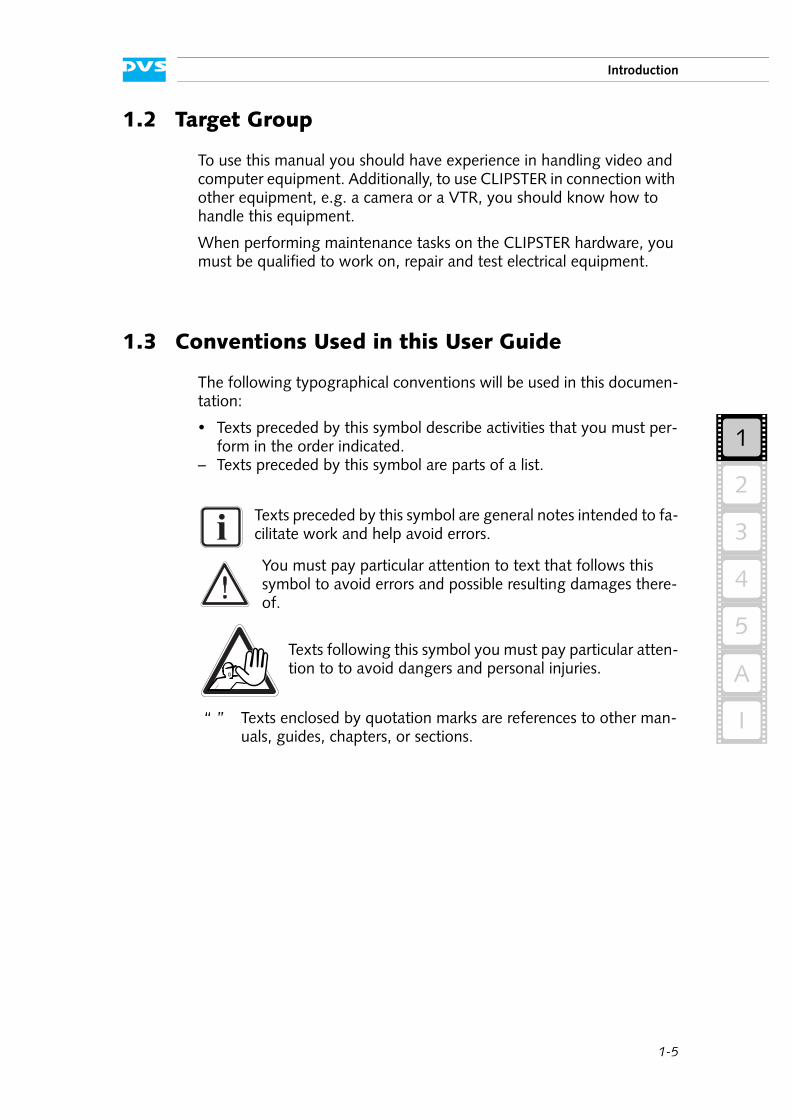
The following typographical conventions will be used in this documen-tation:
Texts preceded by this symbol describe activities that you must per-form in the order indicated.
– Texts preceded by this symbol are parts of a list.
Texts preceded by this symbol are general notes intended to fa-cilitate work and help avoid errors.
You must pay particular attention to text that follows this symbol to avoid errors and possible resulting damages there-of.
Texts following this symbol you must pay particular atten-tion to to avoid dangers and personal injuries.
“ ” Texts enclosed by quotation marks are references to other man-uals, guides, chapters, or sections.
1-6
CLIPSTER Hardware Guide
1.4 Safety Instructions
To use CLIPSTER correctly please heed the following:
General
CLIPSTER has been built according to the applying safety regulations. To minimize the possibility of a faulty operation of the device all man-uals and guides must be available at all times at the operation site. Be-fore installing and/or using CLIPSTER the manuals and guides delivered with CLIPSTER must be read and observed.
– Use CLIPSTER only in apparent good technical order.– The CLIPSTER hardware works with voltages that can be hazardous
to your health. Never work on the system or access its interior with the power cable(s) being plugged in. Make sure the power supply is disconnected from the components you intend to work on.
– Computer hardware contains components that are sensitive to elec-trostatic discharge. If you touch them without precautionary mea-sures, they can be destroyed. Use a wrist strap connected to ground when accessing electronic parts and take care of grounding the sys-tem. Avoid touching the internal components of CLIPSTER when-ever possible.
– Computer hardware contains components that are sensitive to changing voltages. Connecting or disconnecting CLIPSTER to or from peripheral hardware while any of them is switched on may damage the hardware. Switch off all peripheral hardware before connecting or disconnecting anything.
– Use, store and transport CLIPSTER only in compliance with the technical data laid out in section “Technical Data” on page A-4.
– If fluids or solid objects get inside the casing, CLIPSTER must be dis-connected from the power supply immediately. Before using CLIP-STER again, it has to be checked by authorized service personnel.
– Only use a damp tissue without any cleaning agents to clean the casing.
– CLIPSTER must not be misused, abused, physically damaged, neglected, exposed to fire, water or excessive changes in the cli-mate or temperature, or operated outside maximum rating.
– Do not perform any changes or extensions to CLIPSTER whatso-ever.
Please read the following safety instructions carefully before attempting any installation and/or performing any work on CLIPSTER.
If CLIPSTER is not used in compliance with the safety instruc-tions, the warranty and all resulting liability claims will be void.
1-7
Introduction
2
1
3
4
5
I
A
Transportation
CLIPSTER is a very sensitive device. Especially the hard disks of the sys-tem must be handled with greatest care. Therefore, observe in case of transportation:
– Handle CLIPSTER with great care.– Always use the original packing or a similar structured packing for
transportation as detailed in section “Packing Instructions” on page A-15.
– Avoid shocks or vibrations during transport. For longer distances it is recommended to use a lifting truck.
– Keep CLIPSTER as a transportation good dry.– In the warranty period you have to keep the original packing and
use it in case of transportation.
Environmental Conditions
For error-free working and a long service life CLIPSTER needs some ba-sic environmental conditions:
– Do not expose CLIPSTER to sources of heat, such as direct sunlight or a radiator.
– Do not cover or obstruct the ventilation holes of the system (front as well as rear).
– When installing the DVS system in a rack, take care that warmed up air is conducted to the rear of the rack and properly vented away.
– Avoid areas with high humidity or dust. Best operating conditions are given in an air-conditioned site.
– Do not expose CLIPSTER to strong electric or magnetic fields.– Avoid areas where CLIPSTER will be subject to vibrations or shocks.
1-8
CLIPSTER Hardware Guide
1.5 Important Notes
The following provides information about warranty, a note about the conformity of the product and some other general information.
Warranty Information
This product is warranted to be free of defects in materials and work-manship for a period of one year from the date of purchase. DVS ex-tends this Limited Warranty to the original purchaser.
In the event of a defect or failure to confirm to this Limited Warranty, DVS will repair or replace the product without charge. In order to make a claim under this Limited Warranty, the purchaser must notify DVS or their representative in writing of the product failure. In this Limited Warranty the customer must upon DVS’s request return the product to the place of purchase or send the defective device to a given address for the necessary repairs to be performed. In the warranty period the customer must keep the original packing and pack the DVS product in it in case of a product return. If the customer is not satisfied with the repair, DVS will have the option to either attempt a further repair, ex-change the product or refund the purchase price.
This warranty does not cover:
– Products not developed by DVS Digital Video Systems AG.– Products not used in compliance with the safety instructions
detailed in section “Safety Instructions” on page 1-6.– Products on which warranty stickers or product serial numbers have
been removed, altered or rendered illegible.– The costs of installations, removals, transportations, or reinstalla-
tions.– Costs for transportation damages.– Damages caused to any other item.– Any special, indirect or consequential damages, and damages
resulting from loss of use, data or profits, or business interruption.
Declaration of Conformity
This product has been tested according to the applying national and international di-rectives and regulations. Further information about this can be found in section “Confor-mity Declarations” on page A-17.
You have to keep the original packing and use it in case of transportation. Otherwise this warranty will be void.
RoHS2002/95/EC
1-9
Introduction
2
1
3
4
5
I
A
Product Disposal (B2B)
Used electrical and electronic products should not be dis-posed of with general household waste. At the end of its service life you may return the DVS product after appro-priate prior notification to either your local distributor or DVS in Germany. DVS will then take the device free of charge to a waste disposal organization which will recycle and reuse it environmental friendly.
General Notes
Please observe the following general important notes:
CLIPSTER is delivered to you fully preconfigured and opti-mized for a real-time in- and output of uncompressed video streams. Changing any of the settings (e.g. the hardware, software and/or BIOS settings) may lead to a loss of perfor-mance or may even render the system unusable. Re-configur-ing the system anew is in most cases a lengthy procedure. Do not change any of the settings unless you are absolutely sure of what you are doing and what the results would be.
Your DVS system has been tested thoroughly and is very reli-able. However, because of the vast amount of third-party software available, its reactions on the installation of such could not be tested. The installation of third-party software may disrupt the real-time capability and/or limit the function-ality of your system.
Only use the designated storage to store video and audio data. Other storage locations will be too slow for real-time opera-tions.
Leave about 15 % of the overall main storage capacity empty of data for real-time performance reasons.
5U chassis only: Compared to other alarms sounded by the system the alarm buzzer of the power supply is relatively faint. In a loud environment it may be drowned by other noises. When operating CLIPSTER in a loud environment, it is recom-mended to check the state of the power supply units (e.g. via their LEDs, see section “Power Supply” on page 2-21) at reg-ular intervals.

1-10
CLIPSTER Hardware Guide
2-1
2
1
3
4
5
2
I
A
Overview
This chapter provides a detailed overview of the CLIPSTER hardware. First the different hardware variants of CLIPSTER will be explained. Af-ter this the system will be shown in a front and a rear view and all its parts and connectors will be described. For explanatory reasons the sec-tion about the rear also contains some further information about the digital video in- and outputs.
2-2
CLIPSTER Hardware Guide
2.1 Hardware Variants of CLIPSTER
The CLIPSTER system can be delivered in different hardware variants depending on, for example, the amount of the storage that is required or the maximum possible real-time capability of the system. The follow-ing variants are available:
– 4U chassis– 5U chassis
The specialities of these variants will be detailed in this document whenever necessary.
Additionally, DVS can deliver these variants with different rears. Your system may differ from the shown rear views in this document. How-ever, the descriptions detail all the connectors that can be delivered: The ones not present in the shown rear view are described separately.
2.2 Overview of the Front
This section gives an overview of the front of CLIPSTER. After an overall overview of the front the operable front panel at the top of the system will be described first. This will be followed by descriptions of the face-plate and the hard disk array. The section will be concluded with some explanations about the DVD drive.
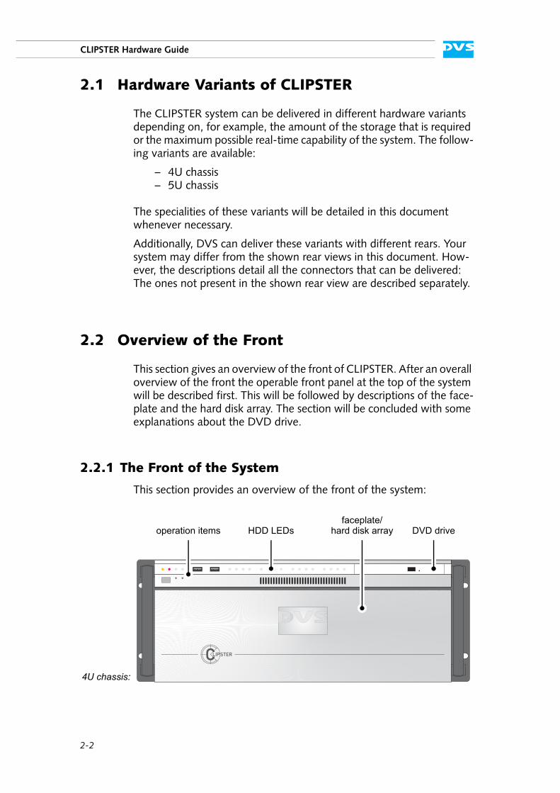
2.2.1 The Front of the System
This section provides an overview of the front of the system:
DVD drivefaceplate/
HDD LEDsoperation items hard disk array
4U chassis:
2-3
Overview
2
1
3
4
5
I
A
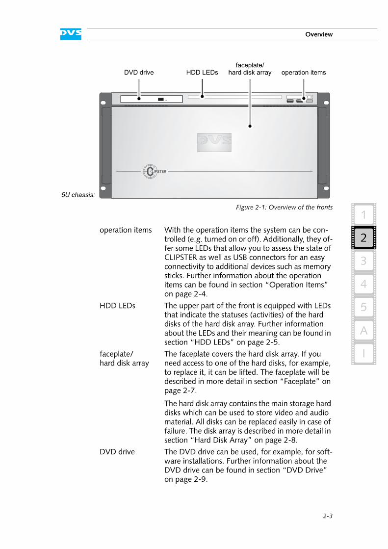
Figure 2-1: Overview of the fronts
operation items With the operation items the system can be con-trolled (e.g. turned on or off). Additionally, they of-fer some LEDs that allow you to assess the state of CLIPSTER as well as USB connectors for an easy connectivity to additional devices such as memory sticks. Further information about the operation items can be found in section “Operation Items” on page 2-4.
HDD LEDs The upper part of the front is equipped with LEDs that indicate the statuses (activities) of the hard disks of the hard disk array. Further information about the LEDs and their meaning can be found in section “HDD LEDs” on page 2-5.
faceplate/hard disk array
The faceplate covers the hard disk array. If you need access to one of the hard disks, for example, to replace it, it can be lifted. The faceplate will be described in more detail in section “Faceplate” on page 2-7.
The hard disk array contains the main storage hard disks which can be used to store video and audio material. All disks can be replaced easily in case of failure. The disk array is described in more detail in section “Hard Disk Array” on page 2-8.
DVD drive The DVD drive can be used, for example, for soft-ware installations. Further information about the DVD drive can be found in section “DVD Drive” on page 2-9.
DVD drivefaceplate/
HDD LEDs operation itemshard disk array
5U chassis:
2-4
CLIPSTER Hardware Guide
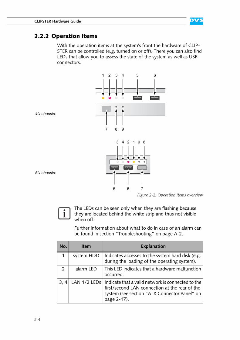
2.2.2 Operation Items
With the operation items at the system’s front the hardware of CLIP-STER can be controlled (e.g. turned on or off). There you can also find LEDs that allow you to assess the state of the system as well as USB connectors.
Figure 2-2: Operation items overview
The LEDs can be seen only when they are flashing because they are located behind the white strip and thus not visible when off.
Further information about what to do in case of an alarm can be found in section “Troubleshooting” on page A-2.
No. Item Explanation
1 system HDD Indicates accesses to the system hard disk (e.g. during the loading of the operating system).
2 alarm LED This LED indicates that a hardware malfunction occurred.
3, 4 LAN 1/2 LEDs Indicate that a valid network is connected to the first/second LAN connection at the rear of the system (see section “ATX Connector Panel” on page 2-17).
1 32 4 5 6
7 8 9
4U chassis:
3 24 1 9 8
5 6 7
5U chassis:
2-5
Overview
2
1
3
4
5
I
A
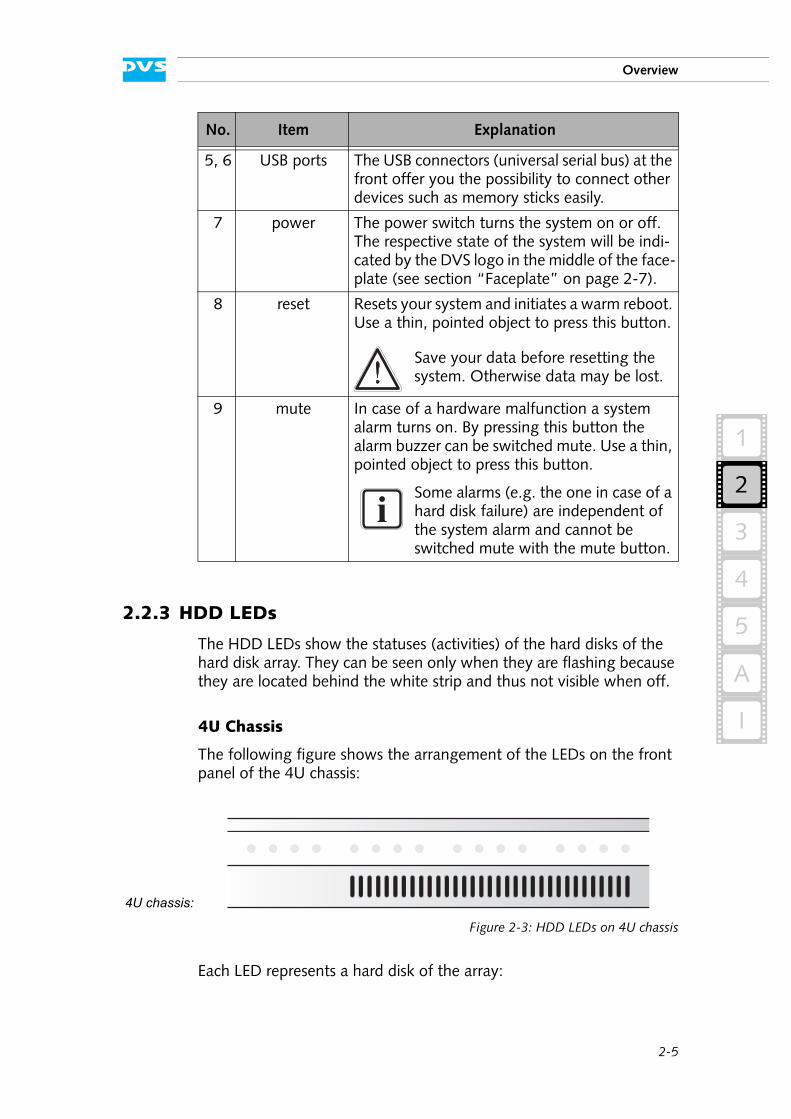
2.2.3 HDD LEDs
The HDD LEDs show the statuses (activities) of the hard disks of the hard disk array. They can be seen only when they are flashing because they are located behind the white strip and thus not visible when off.
4U Chassis
The following figure shows the arrangement of the LEDs on the front panel of the 4U chassis:
Figure 2-3: HDD LEDs on 4U chassis
Each LED represents a hard disk of the array:
5, 6 USB ports The USB connectors (universal serial bus) at the front offer you the possibility to connect other devices such as memory sticks easily.
7 power The power switch turns the system on or off. The respective state of the system will be indi-cated by the DVS logo in the middle of the face-plate (see section “Faceplate” on page 2-7).
8 reset Resets your system and initiates a warm reboot. Use a thin, pointed object to press this button.
Save your data before resetting the system. Otherwise data may be lost.
9 mute In case of a hardware malfunction a system alarm turns on. By pressing this button the alarm buzzer can be switched mute. Use a thin, pointed object to press this button.
Some alarms (e.g. the one in case of a hard disk failure) are independent of the system alarm and cannot be switched mute with the mute button.
No. Item Explanation
4U chassis:
2-6
CLIPSTER Hardware Guide
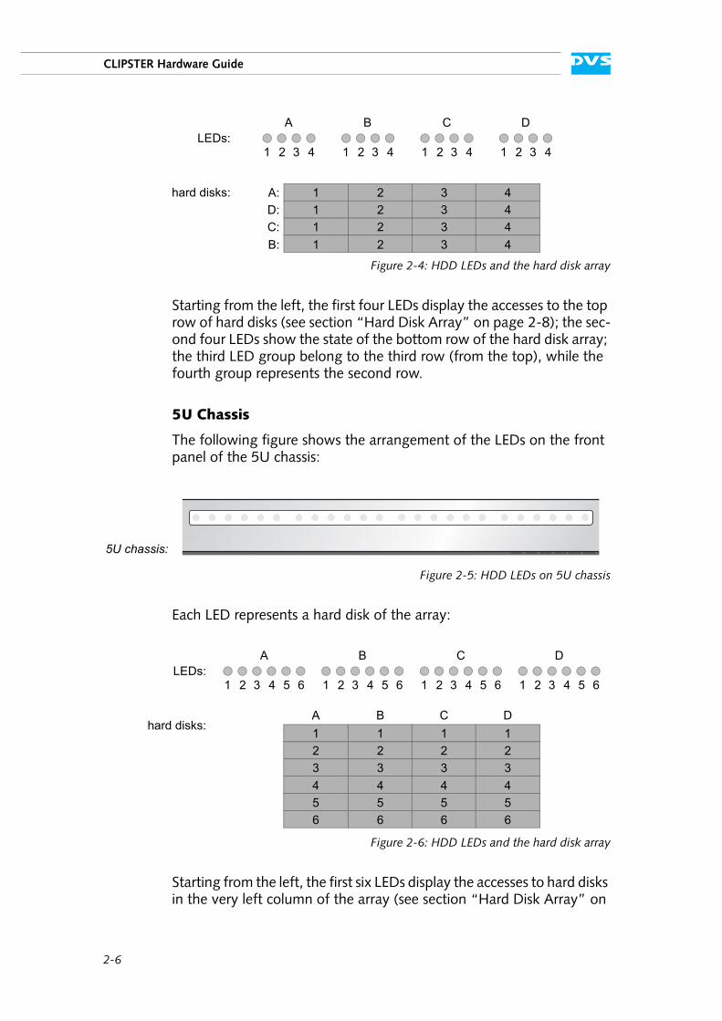
Figure 2-4: HDD LEDs and the hard disk array
Starting from the left, the first four LEDs display the accesses to the top row of hard disks (see section “Hard Disk Array” on page 2-8); the sec-ond four LEDs show the state of the bottom row of the hard disk array; the third LED group belong to the third row (from the top), while the fourth group represents the second row.
5U Chassis
The following figure shows the arrangement of the LEDs on the front panel of the 5U chassis:
Figure 2-5: HDD LEDs on 5U chassis
Each LED represents a hard disk of the array:
Figure 2-6: HDD LEDs and the hard disk array
Starting from the left, the first six LEDs display the accesses to hard disks in the very left column of the array (see section “Hard Disk Array” on
LEDs:
hard disks:
A
1
B C D
2 3 4 1 2 3 4 1 2 3 4 1 2 3 4
1 2 3 41 2 3 41 2 3 41 2 3 4
A:D:C:B:
5U chassis:
A
1
B C D
2 3 4 1 2 3 4 1 2 3 4 1 2 3 4
1 1 1 12 2 2 23 3 3 34 4 4 4
LEDs:
hard disks:
5 5 5 5
5 5 5 5
A B C D
66 6 6
6 6 6 6
2-7
Overview
2
1
3
4
5
I
A
page 2-8), the second six LEDs show the state of the hard disks of the second column, and so on.
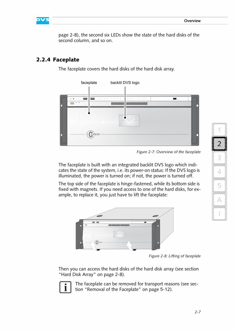
2.2.4 Faceplate
The faceplate covers the hard disks of the hard disk array.
Figure 2-7: Overview of the faceplate
The faceplate is built with an integrated backlit DVS logo which indi-cates the state of the system, i.e. its power-on status: If the DVS logo is illuminated, the power is turned on; if not, the power is turned off.
The top side of the faceplate is hinge-fastened, while its bottom side is fixed with magnets. If you need access to one of the hard disks, for ex-ample, to replace it, you just have to lift the faceplate:
Figure 2-8: Lifting of faceplate
Then you can access the hard disks of the hard disk array (see section “Hard Disk Array” on page 2-8).
The faceplate can be removed for transport reasons (see sec-tion “Removal of the Faceplate” on page 5-12).
faceplate backlit DVS logo
2-8
CLIPSTER Hardware Guide
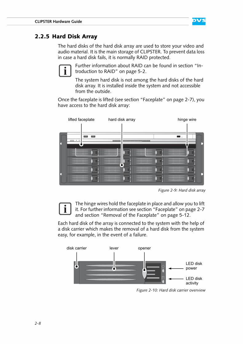
2.2.5 Hard Disk Array
The hard disks of the hard disk array are used to store your video and audio material. It is the main storage of CLIPSTER. To prevent data loss in case a hard disk fails, it is normally RAID protected.
Once the faceplate is lifted (see section “Faceplate” on page 2-7), you have access to the hard disk array:
Figure 2-9: Hard disk array
Each hard disk of the array is connected to the system with the help of a disk carrier which makes the removal of a hard disk from the system easy, for example, in the event of a failure.
Figure 2-10: Hard disk carrier overview
Further information about RAID can be found in section “In-troduction to RAID” on page 5-2.
The system hard disk is not among the hard disks of the hard disk array. It is installed inside the system and not accessible from the outside.
The hinge wires hold the faceplate in place and allow you to lift it. For further information see section “Faceplate” on page 2-7 and section “Removal of the Faceplate” on page 5-12.
lifted faceplate hard disk array hinge wire
lever openerdisk carrier
LED disk
LED diskactivity
power
2-9
Overview
2
1
3
4
5
I
A
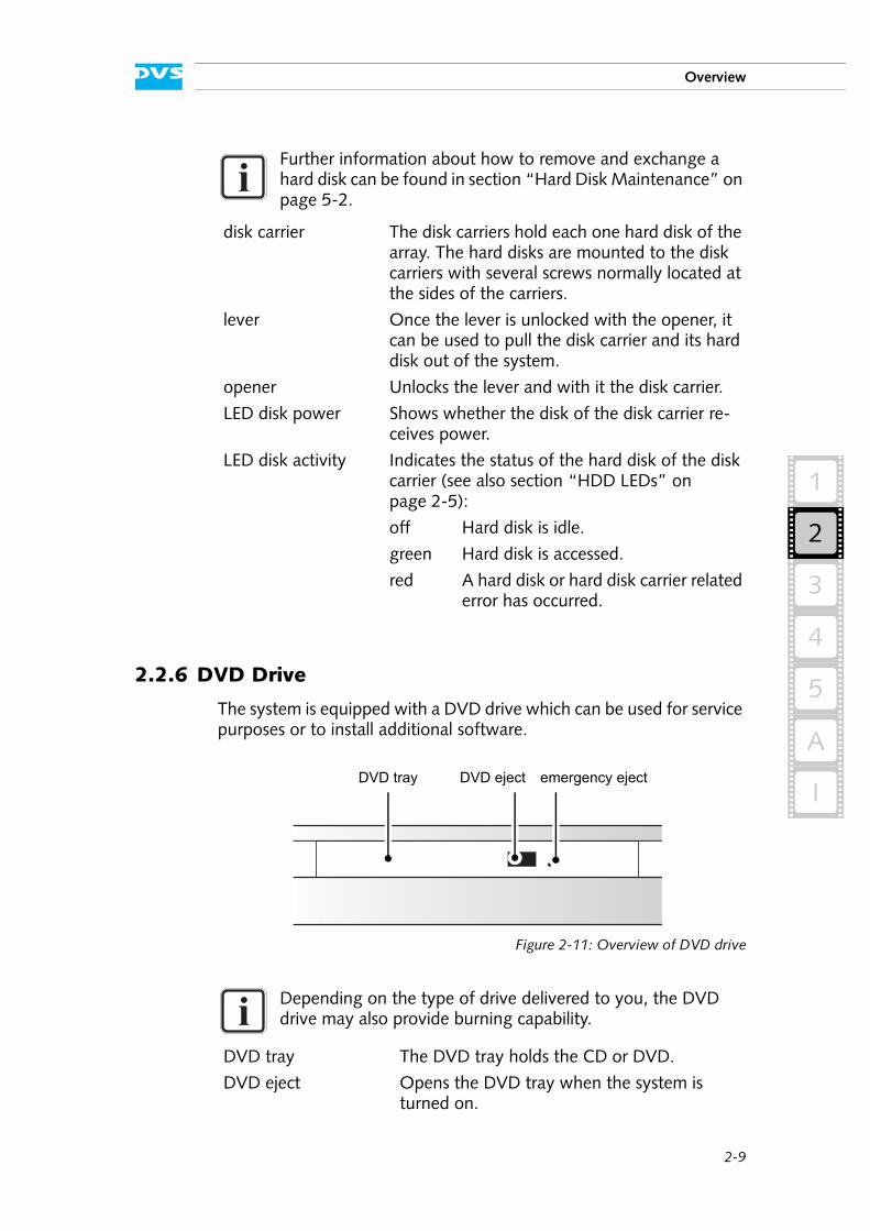
2.2.6 DVD Drive
The system is equipped with a DVD drive which can be used for service purposes or to install additional software.
Figure 2-11: Overview of DVD drive
Further information about how to remove and exchange a hard disk can be found in section “Hard Disk Maintenance” on page 5-2.
disk carrier The disk carriers hold each one hard disk of the array. The hard disks are mounted to the disk carriers with several screws normally located at the sides of the carriers.
lever Once the lever is unlocked with the opener, it can be used to pull the disk carrier and its hard disk out of the system.
opener Unlocks the lever and with it the disk carrier.
LED disk power Shows whether the disk of the disk carrier re-ceives power.
LED disk activity Indicates the status of the hard disk of the disk carrier (see also section “HDD LEDs” on page 2-5):
off Hard disk is idle.
green Hard disk is accessed.
red A hard disk or hard disk carrier related error has occurred.
Depending on the type of drive delivered to you, the DVD drive may also provide burning capability.
DVD tray The DVD tray holds the CD or DVD.
DVD eject Opens the DVD tray when the system is turned on.
DVD tray DVD eject emergency eject

2-10
CLIPSTER Hardware Guide
For further information regarding the operation of the drive, please re-fer to the original manufacturer’s documentation.
emergency eject You can open the DVD tray with the system cut from power: Insert a thin, pointed object into the emergency eject hole. Then the DVD tray opens.
2-11
Overview
2
1
3
4
5
I
A
2.3 Overview of the Rear
This section describes the rear of the system. After an overall overview of the rear some explanatory details about the digital video in- and out-puts are given. Next, the main connector panel will be described, fol-lowed by detailed descriptions of the ATX connector panel, the slot panel connectors and the power supply.
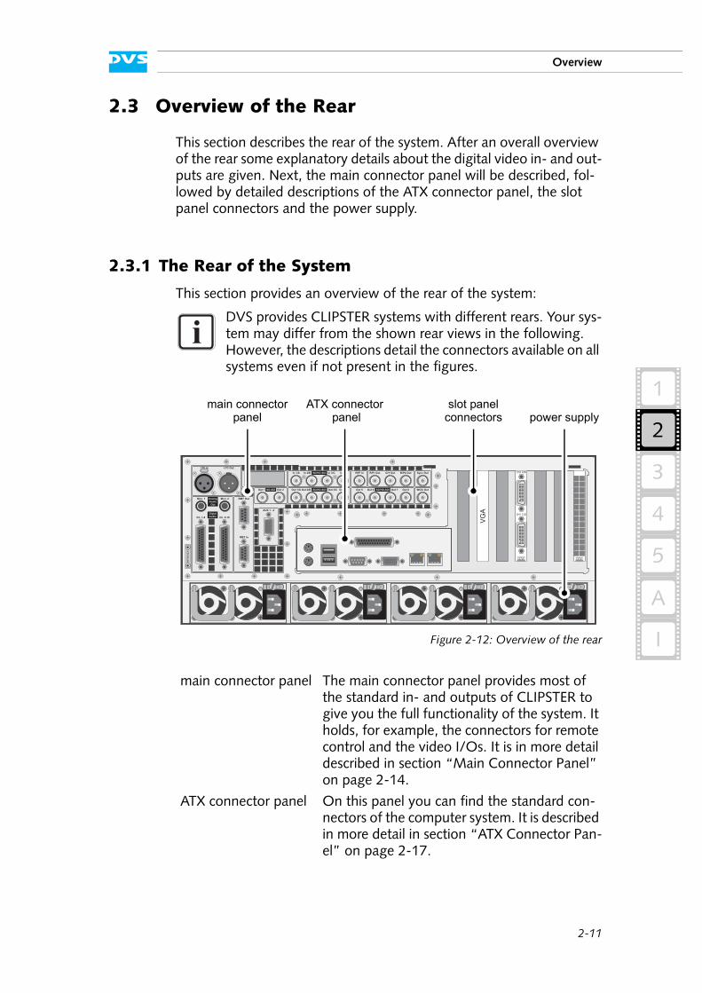
2.3.1 The Rear of the System
This section provides an overview of the rear of the system:
Figure 2-12: Overview of the rear
DVS provides CLIPSTER systems with different rears. Your sys-tem may differ from the shown rear views in the following. However, the descriptions detail the connectors available on all systems even if not present in the figures.
main connector panel The main connector panel provides most of the standard in- and outputs of CLIPSTER to give you the full functionality of the system. It holds, for example, the connectors for remote control and the video I/Os. It is in more detail described in section “Main Connector Panel” on page 2-14.
ATX connector panel On this panel you can find the standard con-nectors of the computer system. It is described in more detail in section “ATX Connector Pan-el” on page 2-17.
987654321
RMT Out
AUX 1 - 2
Out 8Out 5 Out 7Out 6 WClk Out
DVI In Sync OutREF In R/Pr Out G/Y Out B/Pb Out
Out 2/B Out 3/COut 1/A Out 4
Mon. 2Mon. 1
In 1/A In 2/B In 3/C In 4
RMT In
LTC OutLTC In
Ch. 9-16Ch. 1-8
Out 1 Out 2
SD/HD-SDI
SD/HD-SDI SD/HD-SDISD-SDI
AnalogAudioOut
DigtalAudio
PUSH
VG
A
DVI C/D
DVI A/B
power supplymain connector ATX connector slot panel
panel panel connectors
2-12
CLIPSTER Hardware Guide
2.3.2 Digital Video I/Os
This section contains some further information about the digital video in- and outputs of CLIPSTER.
Generally DVS names the input/output channels (connectors/ports) of the digital video signals alphabetically: the main video stream is then available, for instance, on port A and the secondary video stream on port B. However, because some systems offer more channels providing sometimes different functions, the labeling of the ports can be supple-mented by numbers (e.g. ’1/A’, ’2/B’, etc.). To simplify matters when-ever feasible the main video ports (ports A) may be labeled without an alphabetical or numeric structuring.
For YUV you will usually use one channel (the main video ports, mostly labeled ’A’, single link). For YUVA you will need two channels (’A’ for YUV and ’B’ for the key signal). With RGB you will always need two channels (’A’ and ’B’, dual link).
On CLIPSTER the input ports can be switched in software between port A and port C in single-link video modes, and ports A/B and C/4 in dual-link modes. With this you can directly connect two input sources to the system and no extra source switch is required.
During an output the ports C and 4 (dual link; in single link port C only) mirror the output of the channels A/B. The SD-only ports provide at all times a (down-converted) output in YUV SD. Additionally, these signal outputs (ports C, 4 and SD-only) can be provided with customizable in-formation superimposed on the image (’burn-in’ feature, e.g. with timecode, keycode, comments, etc.). All other output channels, i.e. no. 5 to 8, are available during an output in special rasters only (e.g. special 4K rasters, tiling of 4K image to quad HD-SDI).
slot panel connectors The slot panel connectors of CLIPSTER pro-vide, for example, the video I/O panel con-taining video connections and the graphic card panel. Furthermore, if applicable, some addi-tional panels may be present for internal rea-sons or on customer request. More details about the slot panel connectors can be found in section “Slot Panel Connectors” on page 2-18.
power supply The redundant power supply provides the sys-tem with power. It consists of several indepen-dent power supply units: Even if one fails the others will still supply enough power to keep the system operational. Further information about the power supply can be found in sec-tion “Power Supply” on page 2-21.
2-13
Overview
2
1
3
4
5
I
A
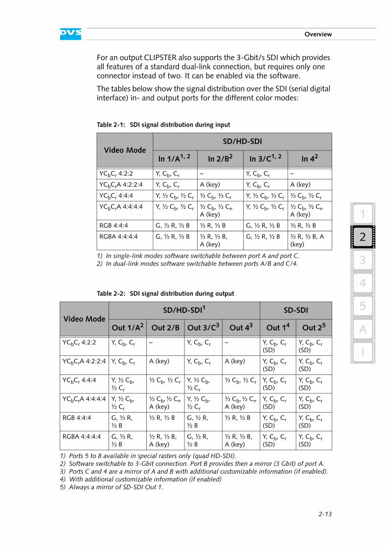
For an output CLIPSTER also supports the 3-Gbit/s SDI which provides all features of a standard dual-link connection, but requires only one connector instead of two. It can be enabled via the software.
The tables below show the signal distribution over the SDI (serial digital interface) in- and output ports for the different color modes:
Table 2-1: SDI signal distribution during input
Video ModeSD/HD-SDI
In 1/A1, 2
1) In single-link modes software switchable between port A and port C.2) In dual-link modes software switchable between ports A/B and C/4.
In 2/B2 In 3/C1, 2 In 42
YCbCr 4:2:2 Y, Cb, Cr – Y, Cb, Cr –
YCbCrA 4:2:2:4 Y, Cb, Cr A (key) Y, Cb, Cr A (key)
YCbCr 4:4:4 Y, ½ Cb, ½ Cr ½ Cb, ½ Cr Y, ½ Cb, ½ Cr ½ Cb, ½ Cr
YCbCrA 4:4:4:4 Y, ½ Cb, ½ Cr ½ Cb, ½ Cr, A (key)
Y, ½ Cb, ½ Cr ½ Cb, ½ Cr, A (key)
RGB 4:4:4 G, ½ R, ½ B ½ R, ½ B G, ½ R, ½ B ½ R, ½ B
RGBA 4:4:4:4 G, ½ R, ½ B ½ R, ½ B, A (key)
G, ½ R, ½ B ½ R, ½ B, A (key)
Table 2-2: SDI signal distribution during output
Video ModeSD/HD-SDI1
1) Ports 5 to 8 available in special rasters only (quad HD-SDI).
SD-SDI
Out 1/A2
2) Software switchable to 3-Gbit connection. Port B provides then a mirror (3 Gbit) of port A.
Out 2/B Out 3/C3
3) Ports C and 4 are a mirror of A and B with additional customizable information (if enabled).
Out 43 Out 14
4) With additional customizable information (if enabled)
Out 25
5) Always a mirror of SD-SDI Out 1.
YCbCr 4:2:2 Y, Cb, Cr – Y, Cb, Cr – Y, Cb, Cr (SD)
Y, Cb, Cr (SD)
YCbCrA 4:2:2:4 Y, Cb, Cr A (key) Y, Cb, Cr A (key) Y, Cb, Cr (SD)
Y, Cb, Cr (SD)
YCbCr 4:4:4 Y, ½ Cb, ½ Cr
½ Cb, ½ Cr Y, ½ Cb, ½ Cr
½ Cb, ½ Cr Y, Cb, Cr (SD)
Y, Cb, Cr (SD)
YCbCrA 4:4:4:4 Y, ½ Cb, ½ Cr
½ Cb, ½ Cr, A (key)
Y, ½ Cb, ½ Cr
½ Cb, ½ Cr, A (key)
Y, Cb, Cr (SD)
Y, Cb, Cr (SD)
RGB 4:4:4 G, ½ R, ½ B
½ R, ½ B G, ½ R, ½ B
½ R, ½ B Y, Cb, Cr (SD)
Y, Cb, Cr (SD)
RGBA 4:4:4:4 G, ½ R, ½ B
½ R, ½ B, A (key)
G, ½ R, ½ B
½ R, ½ B, A (key)
Y, Cb, Cr (SD)
Y, Cb, Cr (SD)
2-14
CLIPSTER Hardware Guide
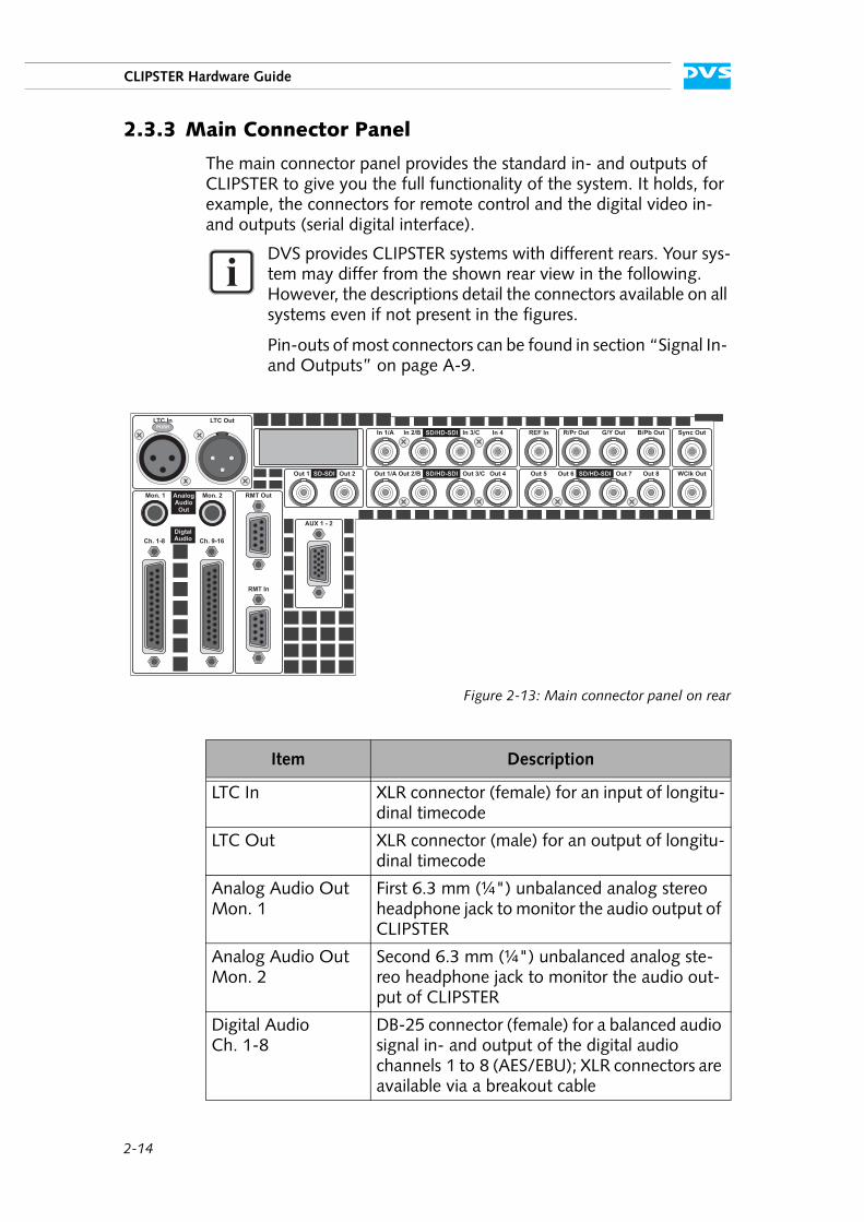
2.3.3 Main Connector Panel
The main connector panel provides the standard in- and outputs of CLIPSTER to give you the full functionality of the system. It holds, for example, the connectors for remote control and the digital video in- and outputs (serial digital interface).
Figure 2-13: Main connector panel on rear
DVS provides CLIPSTER systems with different rears. Your sys-tem may differ from the shown rear view in the following. However, the descriptions detail the connectors available on all systems even if not present in the figures.
Pin-outs of most connectors can be found in section “Signal In- and Outputs” on page A-9.
Item Description
LTC In XLR connector (female) for an input of longitu-dinal timecode
LTC Out XLR connector (male) for an output of longitu-dinal timecode
Analog Audio Out Mon. 1
First 6.3 mm (¼") unbalanced analog stereo headphone jack to monitor the audio output of CLIPSTER
Analog Audio Out Mon. 2
Second 6.3 mm (¼") unbalanced analog ste-reo headphone jack to monitor the audio out-put of CLIPSTER
Digital Audio Ch. 1-8
DB-25 connector (female) for a balanced audio signal in- and output of the digital audio channels 1 to 8 (AES/EBU); XLR connectors are available via a breakout cable
RMT Out
AUX 1 - 2
Out 8Out 5 Out 7Out 6 WClk Out
DVI In Sync OutREF In R/Pr Out G/Y Out B/Pb Out
Out 2/B Out 3/COut 1/A Out 4
Mon. 2Mon. 1
In 1/A In 2/B In 3/C In 4
RMT In
LTC OutLTC In
Ch. 9-16Ch. 1-8
Out 1 Out 2
SD/HD-SDI
SD/HD-SDI SD/HD-SDISD-SDI
AnalogAudioOut
DigtalAudio
PUSH
2-15
Overview
2
1
3
4
5
I
A
Digital Audio Ch. 9-16
DB-25 connector (female) for a balanced audio signal in- and output of the digital audio channels 9 to 16 (AES/EBU); XLR connectors are available via a breakout cable
RMT Out DB-9 connector (female), serial RS-422 inter-face for an output of master control signals
RMT In DB-9 connector (female), serial RS-422 inter-face for an input of slave control signals
AUX 1-2 DB-15 (HD) connector (female), serial RS-422 interface for auxiliary data (e.g. mixer control); a breakout cable to two DB-9 connectors will be included in the delivery
SD-SDI Out 1 BNC connector for an output of digital SD vid-eo signals (serial digital interface); (down-con-verted) output of YUV in single-link; can provide burnt-in information via software
SD-SDI Out 2 BNC connector for an output of digital SD vid-eo signals (serial digital interface); mirror of SD-SDI Out 1
SD/HD-SDI In 1/A BNC connector for an input of digital video sig-nals (serial digital interface, port A); either in-put of YUV in single-link or first stream of YUVA/RGB[A] in dual-link mode; ports A/B can be switched to ports C/4 (dual link, with single link between ports A and C only) in the software
SD/HD-SDI In 2/B BNC connector for an input of digital video sig-nals (serial digital interface, port B); input of the second stream of YUVA or RGB[A] in dual-link mode; ports A/B can be switched to ports C/4 (dual link) in the software
SD/HD-SDI In 3/C BNC connector for an alternative input of digi-tal video signals (serial digital interface, port C); either input of YUV in single-link or first stream of YUVA/RGB[A] in dual-link mode; ports A/B can be switched to ports C/4 (dual link, with single link between ports A and C only) in the software
SD/HD-SDI In 4 BNC connector for an alternative input of digi-tal video signals (serial digital interface); input of the second stream of YUVA or RGB[A] in dual-link mode; ports A/B can be switched to ports C/4 (dual link) in the software
Item Description
2-16
CLIPSTER Hardware Guide
REF In BNC connector for a synchronization of video signals, i.e. the reference input; input of hori-zontal or composite sync depending on soft-ware settings
R/Pr Out BNC connector for an analog output of red in RGB or chroma (R – Y) in YUV
G/Y Out BNC connector for an analog output of green in RGB or luma (Y) in YUV
B/Pb Out BNC connector for an analog output of blue in RGB or chroma (B – Y) in YUV
Sync Out BNC connector for a synchronization of video signals (bilevel as well as trilevel); output of composite sync (S)
SD/HD-SDIOut 1/A
BNC connector for an output of digital video signals (serial digital interface, port A); either output of YUV in single-link or first stream of YUVA/RGB[A] in dual-link mode; it can be configured to 3-Gbit/s SDI in the software
SD/HD-SDIOut 2/B
BNC connector for an output of digital video signals (serial digital interface, port B); output of the second stream of YUVA or RGB[A] in dual-link mode; with 3-Gbit/s SDI this port pro-vides a mirror of port A
SD/HD-SDIOut 3/C
BNC connector for an alternative output of dig-ital video signals (serial digital interface, port C); this port mirrors the output of port A; can provide burnt-in information via software
SD/HD-SDI Out 4 BNC connector for an alternative output of dig-ital video signals (serial digital interface); this port mirrors the output of port B in dual-link modes; can provide burnt-in information via software
SD/HD-SDIOut 5 - 8
BNC connectors for an output of digital video signals in special rasters (quad HD-SDI); used, for example, in special 4K rasters for a tiling of the image to four separate dual-link HD-SDIs
WClk Out BNC connector for a wordclock signal output; used for the synchronization of external audio equipment
Item Description

2-17
Overview
2
1
3
4
5
I
A
The following connectors may be available on other hardware variants. Depending on the variant, they either replace one or more of the con-nectors mentioned above or be available in addition:
2.3.4 ATX Connector Panel
The ATX connector panel on the rear of CLIPSTER holds the connectors of the computer system. It provides the following connections:
Figure 2-14: ATX connector panel on rear
Table 2-3: Replacing or additional connectors on other hardware variants
Item Description
AUX 1 DB-9 connector (female), first serial RS-422 in-terface for auxiliary data (e.g. mixer control)
AUX 2 DB-9 connector (female), second serial RS-422 interface for auxiliary data
DVI In Reserved for future use
SATA External SATA (eSATA) connectors to connect, for example, external storages; internally em-ployed as SATA, meaning you may have to use shorter cables (< 1 m)
SD/HD-SDI In 5 - 8 Reserved for future use
No. Item Explanation
1 mouse PS/2 connector to connect a mouse to the system
2 parallel port DB-25 connector for the connection of an external device, such as a printer
1
3
2
4 5 6 7 8
2-18
CLIPSTER Hardware Guide
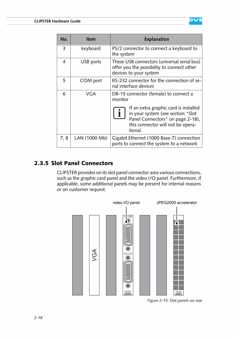
2.3.5 Slot Panel Connectors
CLIPSTER provides on its slot panel connector area various connections, such as the graphic card panel and the video I/O panel. Furthermore, if applicable, some additional panels may be present for internal reasons or on customer request.
Figure 2-15: Slot panels on rear
3 keyboard PS/2 connector to connect a keyboard to the system
4 USB ports These USB connectors (universal serial bus) offer you the possibility to connect other devices to your system
5 COM port RS-232 connector for the connection of se-rial interface devices
6 VGA DB-15 connector (female) to connect a monitor
If an extra graphic card is installed in your system (see section “Slot Panel Connectors” on page 2-18), this connector will not be opera-tional.
7, 8 LAN (1000 Mb) Gigabit Ethernet (1000 Base-T) connection ports to connect the system to a network
No. Item Explanation
VG
A
DVI C/D
DVI A/B
video I/O panel JPEG2000 accelerator

2-19
Overview
2
1
3
4
5
I
A
VGA
The on-board graphic card of the motherboard may not be sufficient to handle digital video. Then the system will be equipped with an addi-tional graphic card. The VGA panel is the panel of this graphic card. If available, the monitor for CLIPSTER has to be connected here.
For further information about the graphic card, please refer to the orig-inal manufacturer’s documentation included in the delivery of CLIP-STER.
Video I/O Panel
The video I/O panel of CLIPSTER holds two video interfaces (DMS-59 connectors) for an output of analog and digital video signals. They can be connected to breakout cables that will then provide each two stan-dard DVI connectors. The breakout cables are included in the delivery of CLIPSTER. Pin-outs of the DMS-59 and DVI connectors can be found in section “Signal In- and Outputs” on page A-9.
The layout of the slot panel area on your system may differ from the figure above: The position of the individual slot panels may vary and additional panels may be installed for internal reasons or on customer request.
If the VGA panel is present in your system, the VGA connector available on the ATX connector panel will not be operational (see chapter “ATX Connector Panel” on page 2-17).
2-20
CLIPSTER Hardware Guide
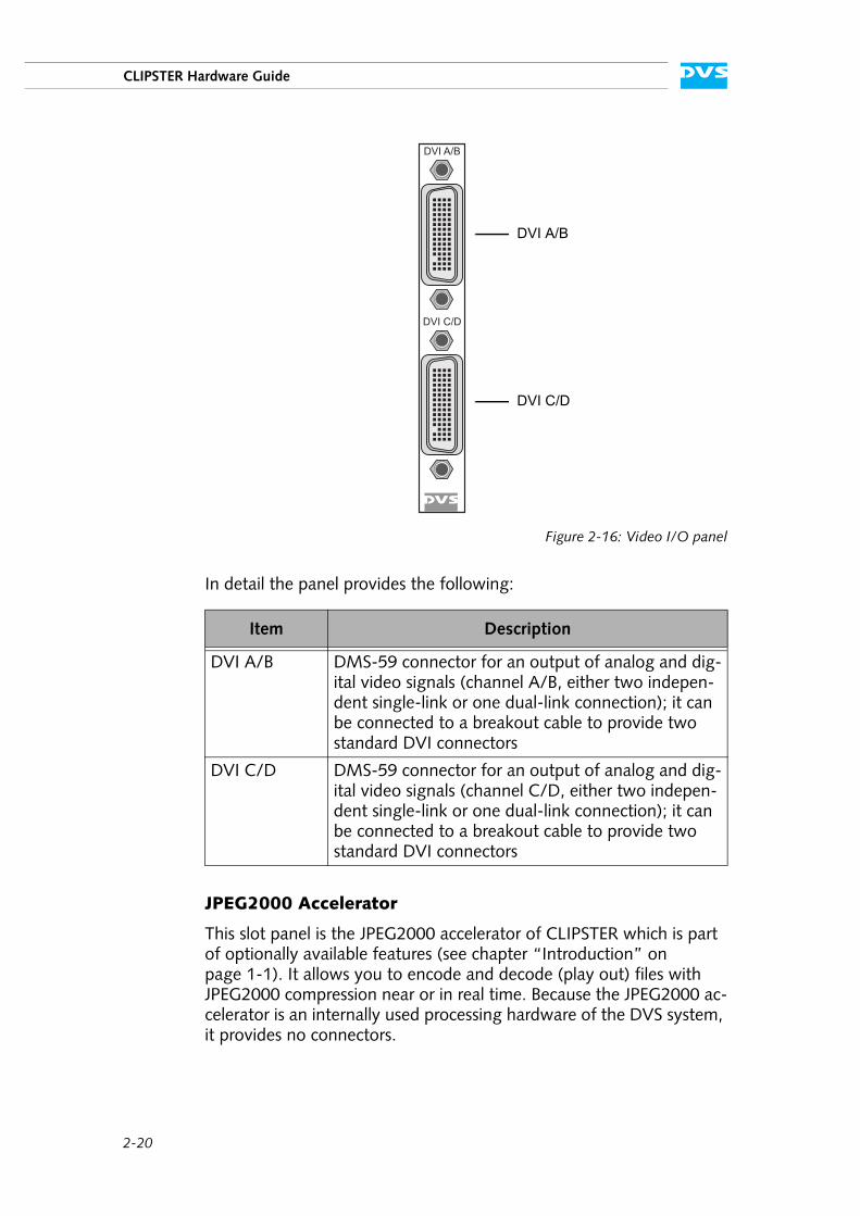
Figure 2-16: Video I/O panel
In detail the panel provides the following:
JPEG2000 Accelerator
This slot panel is the JPEG2000 accelerator of CLIPSTER which is part of optionally available features (see chapter “Introduction” on page 1-1). It allows you to encode and decode (play out) files with JPEG2000 compression near or in real time. Because the JPEG2000 ac-celerator is an internally used processing hardware of the DVS system, it provides no connectors.
Item Description
DVI A/B DMS-59 connector for an output of analog and dig-ital video signals (channel A/B, either two indepen-dent single-link or one dual-link connection); it can be connected to a breakout cable to provide two standard DVI connectors
DVI C/D DMS-59 connector for an output of analog and dig-ital video signals (channel C/D, either two indepen-dent single-link or one dual-link connection); it can be connected to a breakout cable to provide two standard DVI connectors
DVI C/D
DVI A/B
DVI A/B
DVI C/D
2-21
Overview
2
1
3
4
5
I
A
2.3.6 Power Supply
The redundant power supply provides the system with power. It con-sists of several independent power supply units: Even if one fails the others will still offer enough power to keep the system working.
The following provides an overview of one of the power supply units:
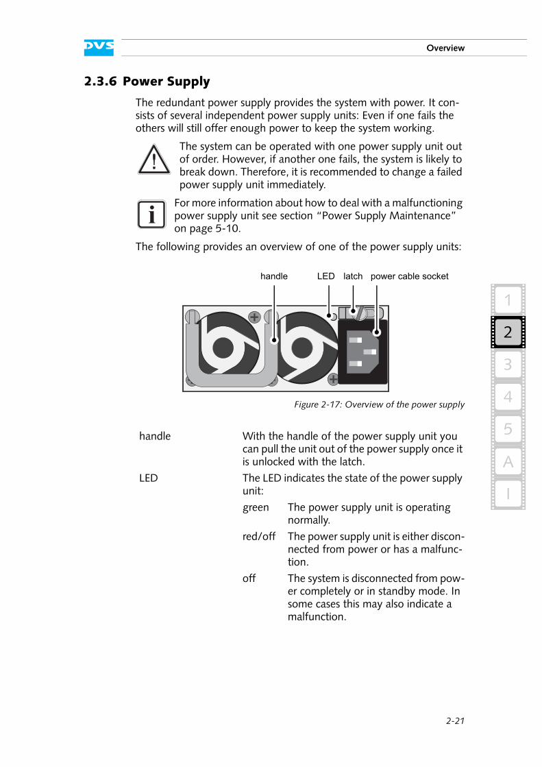
Figure 2-17: Overview of the power supply
The system can be operated with one power supply unit out of order. However, if another one fails, the system is likely to break down. Therefore, it is recommended to change a failed power supply unit immediately.
For more information about how to deal with a malfunctioning power supply unit see section “Power Supply Maintenance” on page 5-10.
handle With the handle of the power supply unit you can pull the unit out of the power supply once it is unlocked with the latch.
LED The LED indicates the state of the power supply unit:
green The power supply unit is operating normally.
red/off The power supply unit is either discon-nected from power or has a malfunc-tion.
off The system is disconnected from pow-er completely or in standby mode. In some cases this may also indicate a malfunction.
latch power cable socketLEDhandle

2-22
CLIPSTER Hardware Guide
latch The latch of a power supply unit locks it in the power supply. With it the unit can be unlocked and pulled out of the power supply with the help of the handle.
power cable socket The socket where the power cable has to be plugged in to provide the system with power.
3-1
4
5
2
1
3
3
I
A
Installation
This chapter describes the installation procedure of the CLIPSTER hard-ware. The system must be installed properly before you can start work-ing with it.
To install the hardware of CLIPSTER perform the following:
Unpack CLIPSTER and its accessories.
Place CLIPSTER on a firm, flat surface within reach of a power out-let or mount it in a rack. For good air circulation and cooling make sure the ventilation holes are not covered.
Connect at least the following computer peripherals:
– Mouse,– keyboard and– a monitor that is operable at a resolution of at least
1024 × 768 pixels (default manufacturing setting).
Connect any other peripheral computer and video equipment. For an overview of the panels and connectors at the system’s rear see section “Overview of the Rear” on page 2-11.
Connect the power cable(s) to the system.
The CLIPSTER hardware is now properly installed and you can switch on the system as described in section “Starting the System” on page 4-1.
Please check your delivery and compare it with the delivery note which has been included in the package on an extra sheet of paper. In case of missing items, please contact your local vendor or DVS immediately.
To make warranty claims you have to keep the original pack-ing and use it in case of a return transportation.
The recommended resolution to run the DVS software is 1600 × 1200 pixels.

3-2
CLIPSTER Hardware Guide
4-1
2
1
3
4
5
4
I
A
Operation
This chapter describes how to operate the CLIPSTER hardware, i.e. it is explained how to start the system and how to shut it down. For both procedures you have to use the power switch of the operation items on the front of the system.
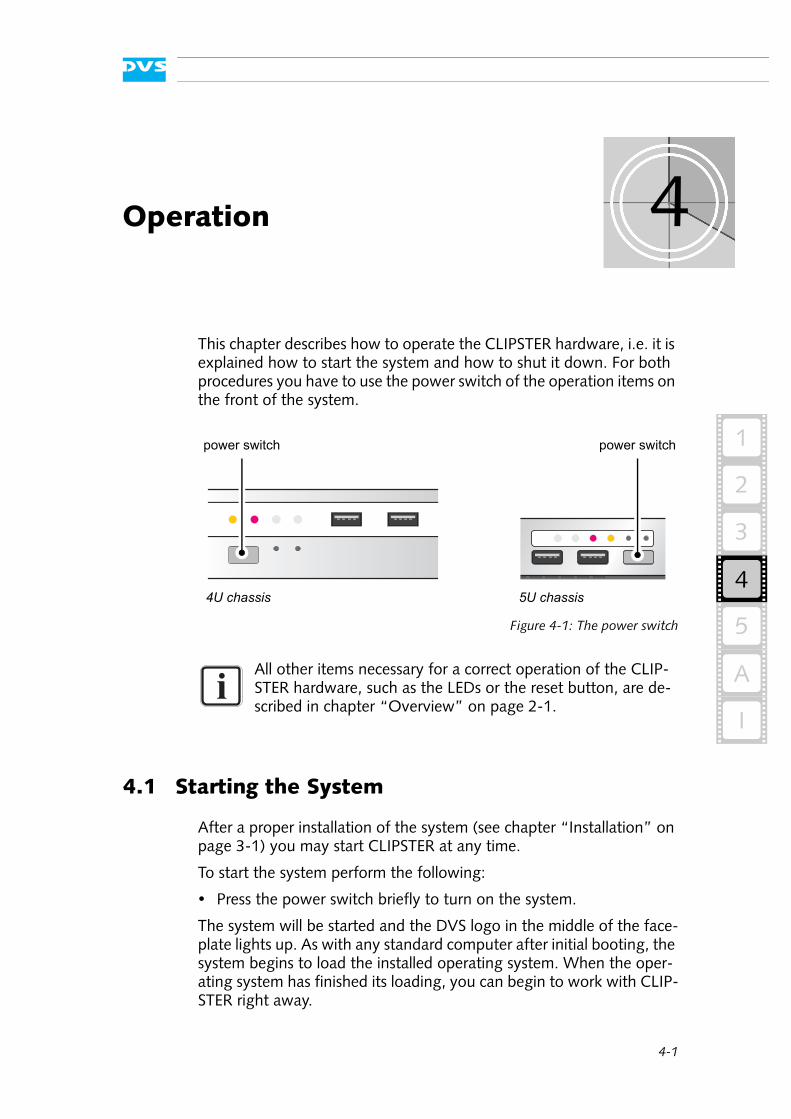
Figure 4-1: The power switch
4.1 Starting the System
After a proper installation of the system (see chapter “Installation” on page 3-1) you may start CLIPSTER at any time.
To start the system perform the following:
Press the power switch briefly to turn on the system.
The system will be started and the DVS logo in the middle of the face-plate lights up. As with any standard computer after initial booting, the system begins to load the installed operating system. When the oper-ating system has finished its loading, you can begin to work with CLIP-STER right away.
All other items necessary for a correct operation of the CLIP-STER hardware, such as the LEDs or the reset button, are de-scribed in chapter “Overview” on page 2-1.
4U chassis
power switch
5U chassis
power switch
4-2
CLIPSTER Hardware Guide
4.2 Shutting Down the System
There are several possibilities to shut down CLIPSTER. All depend on whether the operating system is already loaded or not. Please act ac-cordingly.
To shut down the system perform the following according to the state of the system’s operating system:
With the operating system fully loaded
If the operating system is up and running, there are two ways to shut down your system:
1. Turn the system off by shutting down the operating system the usual way.
The operating system will then save your personal settings and once it has ended, the system will turn off.
2. Alternatively, you can initiate a fast shut down by pressing the power switch briefly.
Some settings will be saved and afterwards the system turns off.
With the operating system not completely loaded
If the operating system is not completely loaded, perform the follow-ing:
Shut down the system by pressing the power switch until the sys-tem turns off.
The system will then shut down immediately.
After a shut-down wait at least ten seconds before starting the system again. This time is needed to safely erase all memory banks of the system.
The fast shut down may not save all your system data and personal settings before the system turns off. Occa-sionally, this may lead to a loss of system data.
Shutting down the system while the operating system is load-ing may lead to corrupted system data. Use this procedure only if absolutely necessary.
5-1
2
1
3
5
4
5
I
A
Maintenance
This chapter explains the maintenance work that you can perform on your own. For each work a detailed procedure description is given. If you experience trouble with the system that cannot be resolved with the work described here or the section “Troubleshooting” on page A-2, please contact your local vendor or DVS directly.
5-2
CLIPSTER Hardware Guide
5.1 Hard Disk Maintenance
This section deals with the possible event of a hard disk failure. First, some introductory information about RAID are provided. After that fol-lows a description how to act when a hard disk fails.
5.1.1 Introduction to RAID
In a system where huge amounts of data are processed, large storage capacities combined with high data throughputs are mandatory. To provide both at the same time it is common practice in the area of video and digital film to configure several hard disks together into a stripe set or RAID. The IT world has defined several ’levels’ of RAID, most of them providing some kind of data protection. Because of this DVS uses RAID 5 to add protection to the stored data as any single disk can fail, but the data will still be recoverable.
The RAID 5 feature makes CLIPSTER tolerant of disk failures. Even with a broken disk an operation can still be continued and, once the failed disk has been replaced, the missing data can be recovered easily.
The main storage of CLIPSTER comprises up to 24 hard disks and the data is striped across these hard disks. Additionally, it provides two RAID controllers that each connects a set of eight hard disks (4U chas-sis; 5U chassis: 12 hard disks). The RAID controllers and their disk sets are independent RAID systems and make the data protection available for the connected hard disks. The information necessary to rebuild a failed hard disk (parity information) is generated and written across the disks connected to a RAID controller. Thus, for each controller present in CLIPSTER one hard disk can fail and the system will still be functional and able to recover data.
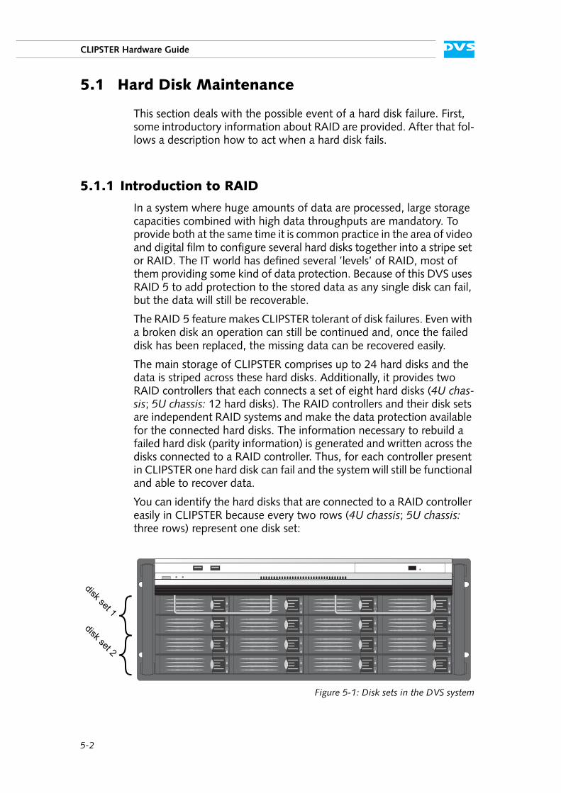
You can identify the hard disks that are connected to a RAID controller easily in CLIPSTER because every two rows (4U chassis; 5U chassis: three rows) represent one disk set:
Figure 5-1: Disk sets in the DVS system
disk set 1disk set 2
5-3
2
1
3
5
4
Maintenance
I
A
If one hard disk within a disk set fails, the missing data can be recalcu-lated due to the parity information stored on the other disks of the set. Thus, a DVS system equipped with RAID 5 can withstand disk failures without losing data or access to data.
5.1.2 Replacing a Hard Disk
In case of a hard disk failure an alarm will be sounded. Then during con-tinuous accesses to the hard disk array you can identify the broken disk easily: It will be the one no longer blinking (either continuously on or off). With this you have the possibility at hand to replace the broken disk.
The hardware replacement of a failed disk can be divided into three steps:
1. Remove the hard disk from the system. 2. Replace the hard disk. 3. Reassemble it into the system.
All steps are explained in the following.
If a second disk within the same disk set fails, your data will be unrecoverable.
An alarm can be caused by a number of reasons. Please refer to section “Troubleshooting” on page A-2 first for further de-tails about what to do in case of an alarm.
If a hard disk of the hard disk array fails, the alarm will be sounded by a RAID controller. It cannot be switched mute with the mute button of the operation items. It can be turned off ei-ther with the RAID software manager or by replacing the bro-ken hard disk.
Data accesses to the hard disk array are still possible because any missing data will be recalculated from the parity informa-tion distributed among the other hard disks of the disk set. Normally this will limit the overall performance and real-time operations may no longer be possible.
Replace the failed disk as soon as possible. If you do not re-place a broken disk in time and another disk fails in the mean-time, your data may be unrecoverable.
5-4
CLIPSTER Hardware Guide
Step 1: Removing the Hard Disk
The hard disks that are accessible at the front of the system store the data of the main storage. Because they are connected to the whole sys-tem with the help of disk carriers, they can be removed easily.
To remove a hard disk from the system perform the following:
If appropriate, stop all accesses to the hard disk array of your sys-tem, for example, by exiting the video system software and sever-ing the network connections.
Lift the faceplate of the system (see section “Faceplate” on page 2-7).
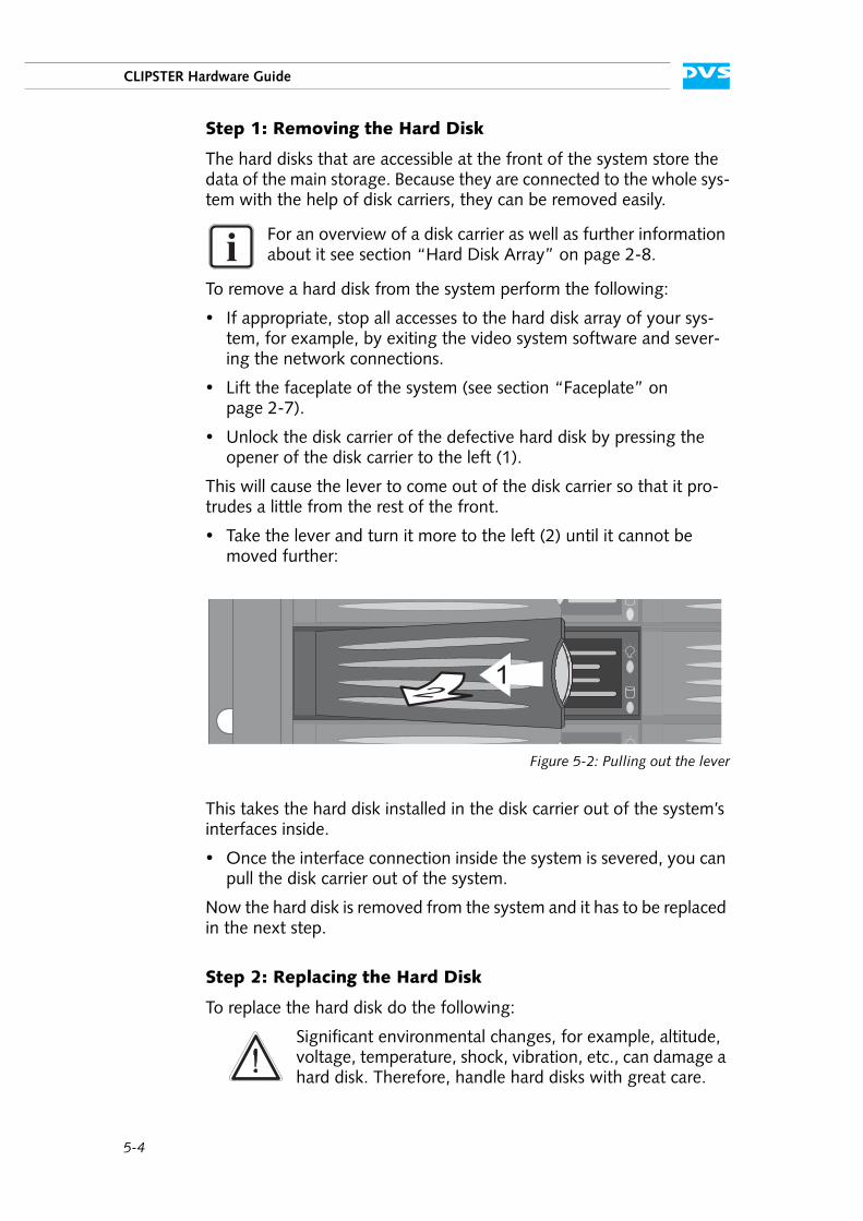
Unlock the disk carrier of the defective hard disk by pressing the opener of the disk carrier to the left (1).
This will cause the lever to come out of the disk carrier so that it pro-trudes a little from the rest of the front.
Take the lever and turn it more to the left (2) until it cannot be moved further:
Figure 5-2: Pulling out the lever
This takes the hard disk installed in the disk carrier out of the system’s interfaces inside.
Once the interface connection inside the system is severed, you can pull the disk carrier out of the system.
Now the hard disk is removed from the system and it has to be replaced in the next step.
Step 2: Replacing the Hard Disk
To replace the hard disk do the following:
For an overview of a disk carrier as well as further information about it see section “Hard Disk Array” on page 2-8.
Significant environmental changes, for example, altitude, voltage, temperature, shock, vibration, etc., can damage a hard disk. Therefore, handle hard disks with great care.
5-5
2
1
3
5
4
Maintenance
I
A
Unscrew the screws that fix the hard disk to the disk carrier.
Exchange the broken disk with a new one and assemble it in the disk carrier with the screws.
After that the hard disk is replaced and the disk carrier with the new disk has to be reassembled in the system.
Step 3: Reassembling the Hard Disk
After replacing the hard disk, the disk carrier with the new disk has to be reassembled in the system. For this perform the following:
Slide the disk carrier back into its shaft at the front of the disk array.
Push it completely back into the shaft by applying pressure to the disk carrier directly (i.e. do not use the lever to push the carrier). Move it until you feel the resistance of the hard disk interface inside the system and until the lever retracts by itself from the pushing.
Then simply close the lever until it snaps back in place which as a result will slide the carrier completely back in.
Once the faceplate of the DVS system is back in place, the replacement of the hard disk is finished. After several minutes the replaced hard disk will be automatically recognized by the system. Then the rebuild of the data will be initiated on its own. Once the system has finished the re-build, CLIPSTER will be fully operational again.
It is best to use the same brand and type of hard disk again. Otherwise a loss of performance might occur.
It is important that you do not use the lever to insert the disk carrier. Apply an even pressure only to the carrier di-rectly until the lever moves back by itself.
The disk carrier of the replaced disk should be level with the others at the front of the system’s disk array.
A rebuild takes several hours. It is strongly recommended to avoid accesses to the hard disk array during this time, other-wise it may take considerably longer.
5-6
CLIPSTER Hardware Guide
5.2 Opening and Closing the Casing
Some tasks described in this manual require an opening of the system’s casing and the closing of it afterwards once the intended work is fin-ished. Both tasks will be explained in this section.
5.2.1 Opening the Casing
To open the casing of the CLIPSTER system perform the following:
If appropriate, shut down the system.
Disconnect all power cords from the system.
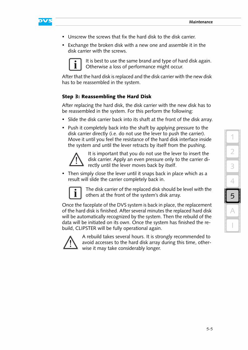
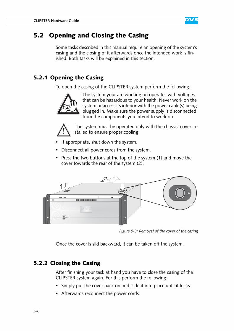
Press the two buttons at the top of the system (1) and move the cover towards the rear of the system (2).
Figure 5-3: Removal of the cover of the casing
Once the cover is slid backward, it can be taken off the system.
5.2.2 Closing the Casing
After finishing your task at hand you have to close the casing of the CLIPSTER system again. For this perform the following:
Simply put the cover back on and slide it into place until it locks.
Afterwards reconnect the power cords.
The system your are working on operates with voltages that can be hazardous to your health. Never work on the system or access its interior with the power cable(s) being plugged in. Make sure the power supply is disconnected from the components you intend to work on.
The system must be operated only with the chassis’ cover in-stalled to ensure proper cooling.
12

5-7
2
1
3
5
4
Maintenance
I
A
With this the task to close the casing is finished and you can turn the system back on at any time.
5.3 Fan Maintenance
To cool the many hard disks installed in the system as well as the other electronic parts (e.g. the motherboard), the system is equipped with several fans that can be exchanged in case of a failure easily. This sec-tion describes what to do if a fan failure takes place.
When a fan failure occurs, you will be notified by a lit alarm LED and the sounding of an alarm buzzer of the system. The alarm can be switched mute with the mute button at the front of the system (see sec-tion “Operation Items” on page 2-4). Then you have to do the follow-ing to exchange the failed fan:
Open the casing of the system as described in section “Opening the Casing” on page 5-6.
An alarm can be caused by a number of reasons. Please refer to section “Troubleshooting” on page A-2 first for further de-tails about what to do in case of an alarm.
The system your are working on operates with voltages that can be hazardous to your health. Never work on the system or access its interior with the power cable(s) being plugged in. Make sure the power supply is disconnected from the components you intend to work on.
Fan maintenance should only be performed by personnel qualified for handling and testing electrical equipment.
Computer hardware contains components that are sensitive to electrostatic discharge. If you touch them without precau-tionary measures, they can be destroyed. Use a wrist strap connected to ground when accessing electronic parts and take care of grounding the system. Avoid touching the inter-nal components of the computer system.
5-8
CLIPSTER Hardware Guide
With the casing of the system open, you can now test the fans. For this you have to plug in the power supply again.
Reconnect the power cords.
Press the power switch to turn on the system.
Observe the fans and memorize the failed one (the fan not revolv-ing is the broken one).
Press the power switch until the system turns off.
After this disconnect the power cables once again.
With the broken fan identified you can replace it. For this perform the following:
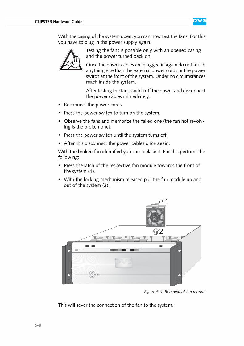
Press the latch of the respective fan module towards the front of the system (1).
With the locking mechanism released pull the fan module up and out of the system (2).
Figure 5-4: Removal of fan module
This will sever the connection of the fan to the system.
Testing the fans is possible only with an opened casing and the power turned back on.
Once the power cables are plugged in again do not touch anything else than the external power cords or the power switch at the front of the system. Under no circumstances reach inside the system.
After testing the fans switch off the power and disconnect the power cables immediately.
1
2
5-9
2
1
3
5
4
Maintenance
I
A
Unscrew the finger protection grille from the broken fan and after-wards screw off the fan from the fan bracket.
Replace the broken fan with a new one and reassemble the fan module: Screw the fan to the fan bracket and afterwards the finger protection grille to the fan.
Re-insert the repaired fan module into the system.
Next close the casing of the system as described in section “Closing the Casing” on page 5-6.
With the last step finished you have successfully replaced the defective fan module. Once the system is turned on, no alarm should be sounded anymore.
Only use original manufacturer spare parts. Other spare parts might damage your system.
See to it that the fan module plugs properly into the system’s fan interface and that, when completely inserted, the lock-ing mechanism snaps back into its locked position.
5-10
CLIPSTER Hardware Guide
5.4 Power Supply Maintenance
The redundant power supply provides the system with power. It is a very reliable and enduring part of the system because it consists of sev-eral independent power supply units: Even if one fails the others will still offer enough power to keep the system working.
When a power supply unit failure occurs, you will be notified by the sounding of an alarm buzzer of the system. The alarm can be switched mute with the mute button at the front of the system (see section “Op-eration Items” on page 2-4).
Each power supply unit in the CLIPSTER system is hot-swappable, so you can safely replace it with the system running. Follow these steps to replace a power supply unit:
Take a look at the power supply at the rear of the system and examine the LEDs of the units. The LED of the malfunctioning power supply unit should be either extinguished or lit in red.
Next unplug the power cord from this power supply unit.
Take the handle of the respective unit and use the unit’s latch to unlock it.
Then pull the unit at its handle out of the power supply.
Change the power supply unit against a new and operable one.
Slide the new unit into the power supply until it clicks into place.
The system can be operated with one power supply unit out of order. However, if another one fails, the system is likely to break down. Therefore, it is recommended to change a failed power supply unit immediately.
An alarm can be caused by a number of reasons. Please refer to section “Troubleshooting” on page A-2 first for further de-tails about what to do in case of an alarm.
For an overview of a power supply unit see section “Power Supply” on page 2-21.
Do not reach inside the system when removing a power supply unit or when the unit is out of the system.
Only use original manufacturer spare parts. Other spare parts might damage your system.
When completely inserted please observe that the latch is truly in place and locking the unit.
5-11
2
1
3
5
4
Maintenance
I
A
Connect the power source (the power cord) to the newly installed power supply unit.
After that check the LED indicating the status of the power supply unit: If it is lit up in green, the unit is working properly.
With this the power supply unit has been replaced successfully.
5-12
CLIPSTER Hardware Guide
5.5 Removal of the Faceplate
The faceplate of the system can be removed, for example, for trans-ports. For this perform the following:
Lift the faceplate of the system (see section “Faceplate” on page 2-7).
Beneath it you will see a cable with a jack connection that supplies the DVS logo of the faceplate with power.
Unplug the jack connection.
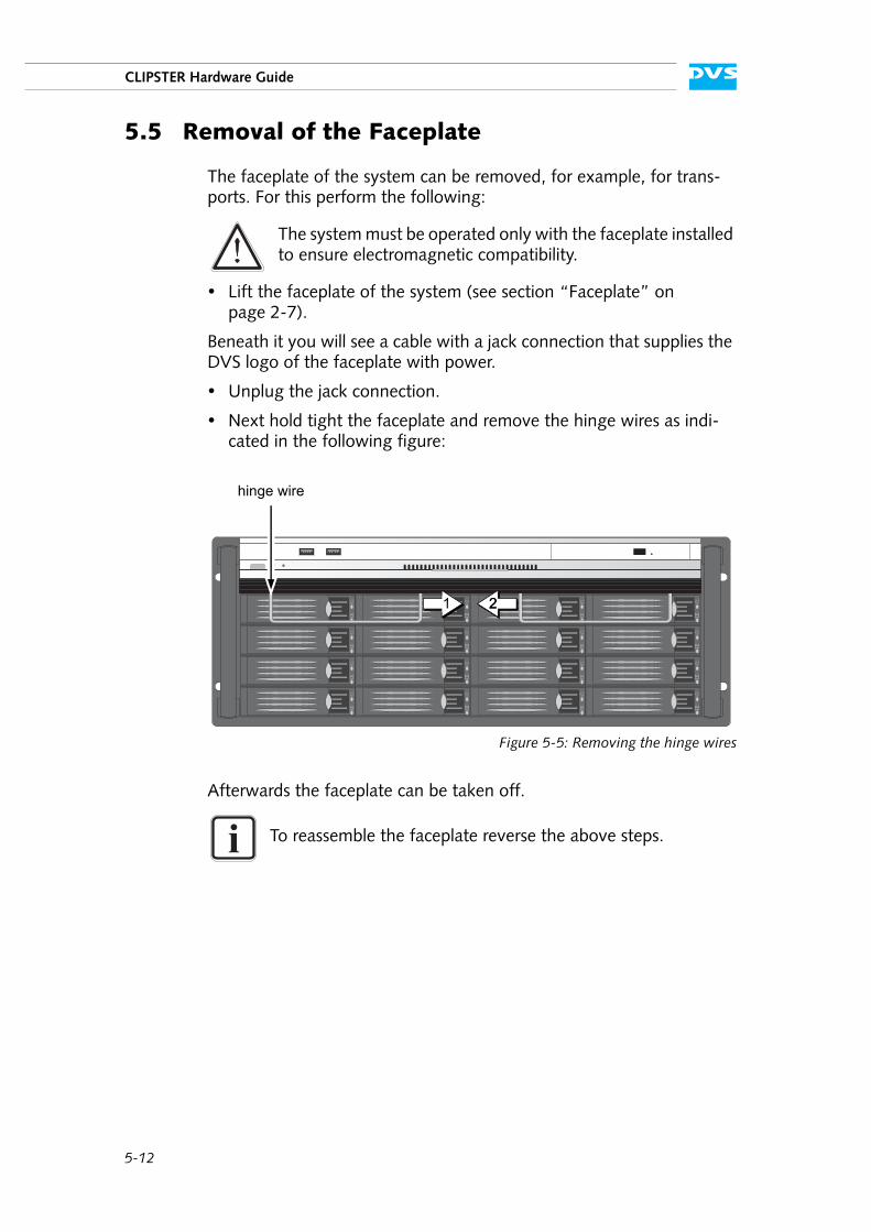
Next hold tight the faceplate and remove the hinge wires as indi-cated in the following figure:
Figure 5-5: Removing the hinge wires
Afterwards the faceplate can be taken off.
The system must be operated only with the faceplate installed to ensure electromagnetic compatibility.
To reassemble the faceplate reverse the above steps.
hinge wire
1 22
A-1
2
1
3
4
5
I
A
AAppendix
This chapter first gives some hints how to resolve irregularities during operation. After that technical data and general information about CLIPSTER are provided.
A-2
CLIPSTER Hardware Guide
A.1 Troubleshooting
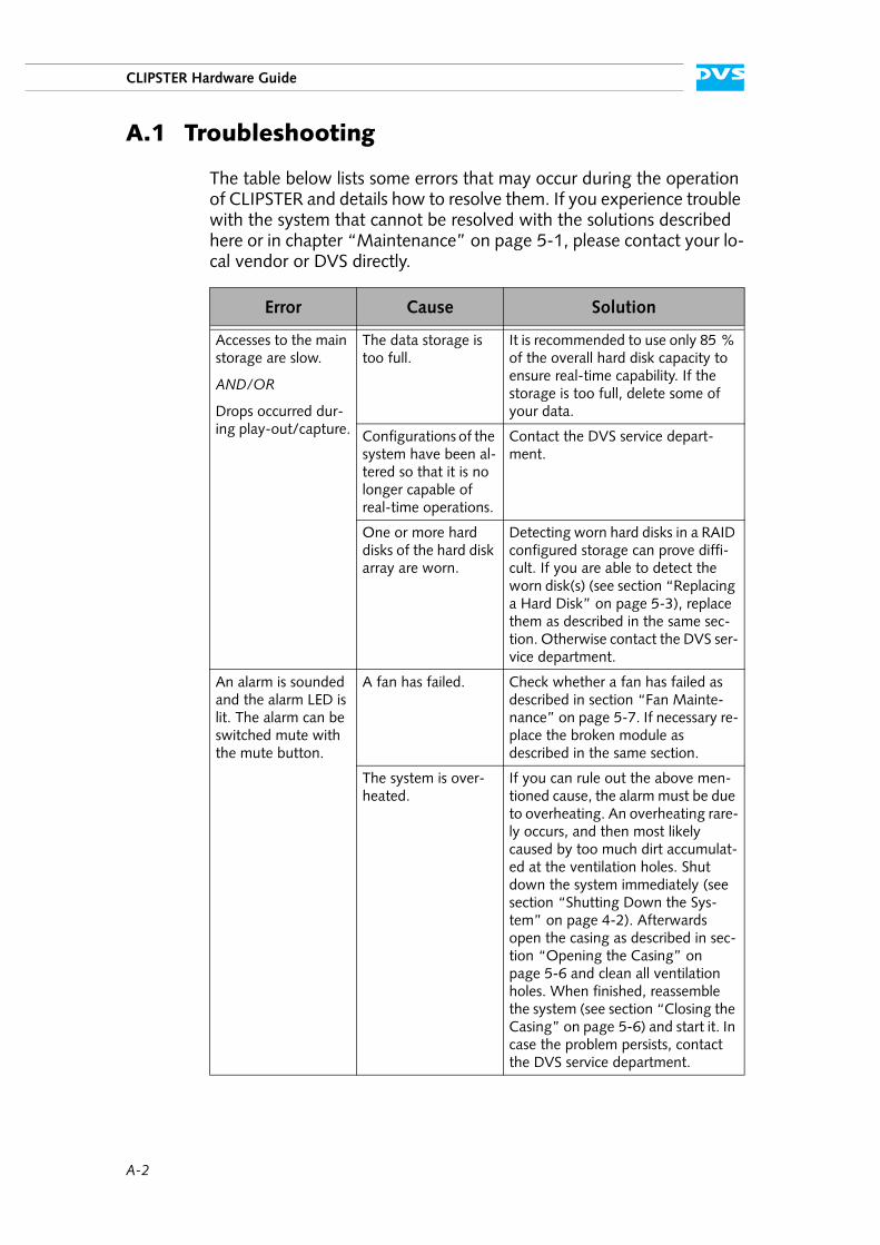
The table below lists some errors that may occur during the operation of CLIPSTER and details how to resolve them. If you experience trouble with the system that cannot be resolved with the solutions described here or in chapter “Maintenance” on page 5-1, please contact your lo-cal vendor or DVS directly.
Error Cause Solution
Accesses to the main storage are slow.
AND/OR
Drops occurred dur-ing play-out/capture.
The data storage is too full.
It is recommended to use only 85 % of the overall hard disk capacity to ensure real-time capability. If the storage is too full, delete some of your data.
Configurations of the system have been al-tered so that it is no longer capable of real-time operations.
Contact the DVS service depart-ment.
One or more hard disks of the hard disk array are worn.
Detecting worn hard disks in a RAID configured storage can prove diffi-cult. If you are able to detect the worn disk(s) (see section “Replacing a Hard Disk” on page 5-3), replace them as described in the same sec-tion. Otherwise contact the DVS ser-vice department.
An alarm is sounded and the alarm LED is lit. The alarm can be switched mute with the mute button.
A fan has failed. Check whether a fan has failed as described in section “Fan Mainte-nance” on page 5-7. If necessary re-place the broken module as described in the same section.
The system is over-heated.
If you can rule out the above men-tioned cause, the alarm must be due to overheating. An overheating rare-ly occurs, and then most likely caused by too much dirt accumulat-ed at the ventilation holes. Shut down the system immediately (see section “Shutting Down the Sys-tem” on page 4-2). Afterwards open the casing as described in sec-tion “Opening the Casing” on page 5-6 and clean all ventilation holes. When finished, reassemble the system (see section “Closing the Casing” on page 5-6) and start it. In case the problem persists, contact the DVS service department.
A-3
2
1
3
4
5
Appendix
I
A
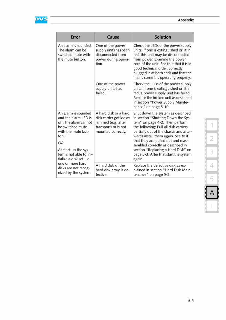
An alarm is sounded. The alarm can be switched mute with the mute button.
One of the power supply units has been disconnected from power during opera-tion.
Check the LEDs of the power supply units. If one is extinguished or lit in red, this unit may be disconnected from power. Examine the power cord of the unit. See to it that it is in good technical order, correctly plugged in at both ends and that the mains current is operating properly.
One of the power supply units has failed.
Check the LEDs of the power supply units. If one is extinguished or lit in red, a power supply unit has failed. Replace the broken unit as described in section “Power Supply Mainte-nance” on page 5-10.
An alarm is sounded and the alarm LED is off. The alarm cannot be switched mute with the mute but-ton.
OR
At start-up the sys-tem is not able to ini-tialize a disk set, i.e. one or more hard disks are not recog-nized by the system.
A hard disk or a hard disk carrier got loose/jammed (e.g. after transport) or is not mounted correctly.
Shut down the system as described in section “Shutting Down the Sys-tem” on page 4-2. Then perform the following: Pull all disk carriers partially out of the chassis and after-wards install them again. See to it that they are pulled out and reas-sembled correctly as described in section “Replacing a Hard Disk” on page 5-3. After that start the system again.
A hard disk of the hard disk array is de-fective.
Replace the defective disk as ex-plained in section “Hard Disk Main-tenance” on page 5-2.
Error Cause Solution
A-4
CLIPSTER Hardware Guide
A.2 Technical Data
This section provides technical data of CLIPSTER.
A.2.1 General Technical Data
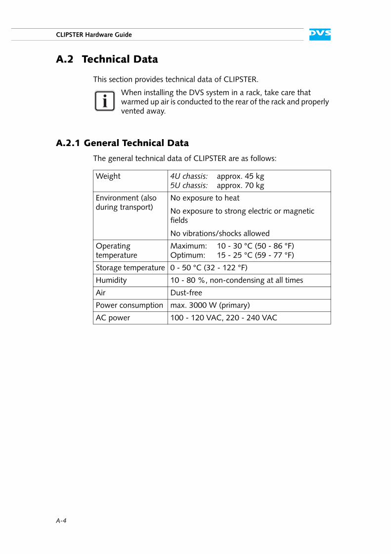
The general technical data of CLIPSTER are as follows:
When installing the DVS system in a rack, take care that warmed up air is conducted to the rear of the rack and properly vented away.
Weight 4U chassis: approx. 45 kg5U chassis: approx. 70 kg
Environment (also during transport)
No exposure to heat
No exposure to strong electric or magnetic fields
No vibrations/shocks allowed
Operating temperature
Maximum: 10 - 30 °C (50 - 86 °F)Optimum: 15 - 25 °C (59 - 77 °F)
Storage temperature 0 - 50 °C (32 - 122 °F)
Humidity 10 - 80 %, non-condensing at all times
Air Dust-free
Power consumption max. 3000 W (primary)
AC power 100 - 120 VAC, 220 - 240 VAC
A-5
2
1
3
4
5
Appendix
I
A
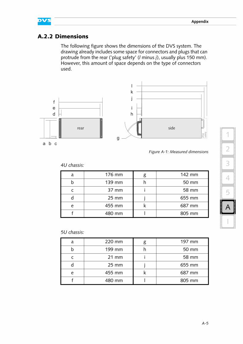
A.2.2 Dimensions
The following figure shows the dimensions of the DVS system. The drawing already includes some space for connectors and plugs that can protrude from the rear (’plug safety’ (l minus j), usually plus 150 mm). However, this amount of space depends on the type of connectors used.
Figure A-1: Measured dimensions
4U chassis:
5U chassis:
a 176 mm g 142 mm
b 139 mm h 50 mm
c 37 mm i 58 mm
d 25 mm j 655 mm
e 455 mm k 687 mm
f 480 mm l 805 mm
a 220 mm g 197 mm
b 199 mm h 50 mm
c 21 mm i 58 mm
d 25 mm j 655 mm
e 455 mm k 687 mm
f 480 mm l 805 mm
plug
safe
ty
siderear
21,0
0
199,1
0
220,1
0
25,30
455,30
480,60
g
49,00
56,00
660,10
688,10
720,10
d
e
f
a b c
h
i
j
k
l
g
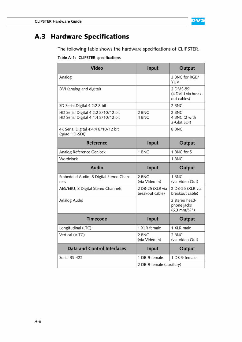
A-6
CLIPSTER Hardware Guide
A.3 Hardware Specifications
The following table shows the hardware specifications of CLIPSTER.
Table A-1: CLIPSTER specifications
Video Input Output
Analog 3 BNC for RGB/YUV
DVI (analog and digital) 2 DMS-59(4 DVI-I via break-out cables)
SD Serial Digital 4:2:2 8 bit 2 BNC
HD Serial Digital 4:2:2 8/10/12 bitHD Serial Digital 4:4:4 8/10/12 bit
2 BNC4 BNC
2 BNC4 BNC (2 with 3-Gbit SDI)
4K Serial Digital 4:4:4 8/10/12 bit (quad HD-SDI)
8 BNC
Reference Input Output
Analog Reference Genlock 1 BNC 1 BNC for S
Wordclock 1 BNC
Audio Input Output
Embedded Audio, 8 Digital Stereo Chan-nels
2 BNC (via Video In)
1 BNC (via Video Out)
AES/EBU, 8 Digital Stereo Channels 2 DB-25 (XLR via breakout cable)
2 DB-25 (XLR via breakout cable)
Analog Audio 2 stereo head-phone jacks (6.3 mm/¼")
Timecode Input Output
Longitudinal (LTC) 1 XLR female 1 XLR male
Vertical (VITC) 2 BNC (via Video In)
2 BNC (via Video Out)
Data and Control Interfaces Input Output
Serial RS-422 1 DB-9 female 1 DB-9 female
2 DB-9 female (auxiliary)
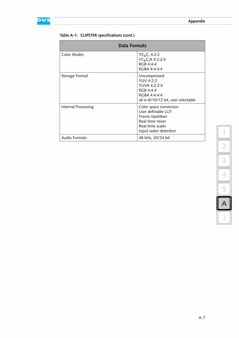
A-7
2
1
3
4
5
Appendix
I
A
Data Formats
Color Modes YCbCr 4:2:2YCbCrA 4:2:2:4RGB 4:4:4RGBA 4:4:4:4
Storage Format UncompressedYUV 4:2:2YUVA 4:2:2:4RGB 4:4:4RGBA 4:4:4:4all in 8/10/12 bit, user selectable
Internal Processing Color space conversionUser definable LUTFrame repetitionReal-time mixerReal-time scalerInput raster detection
Audio Formats 48 kHz, 20/24 bit
Table A-1: CLIPSTER specifications (cont.)
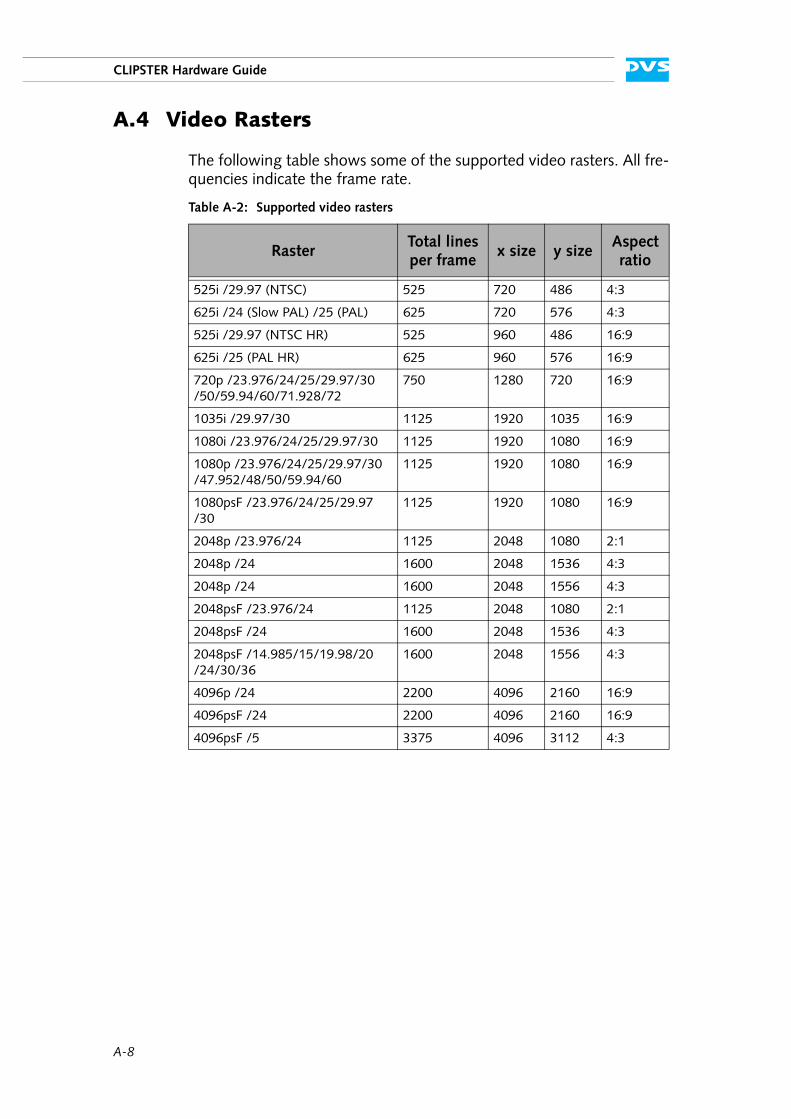
A-8
CLIPSTER Hardware Guide
A.4 Video Rasters
The following table shows some of the supported video rasters. All fre-quencies indicate the frame rate.
Table A-2: Supported video rasters
RasterTotal lines per frame
x size y sizeAspect ratio
525i /29.97 (NTSC) 525 720 486 4:3
625i /24 (Slow PAL) /25 (PAL) 625 720 576 4:3
525i /29.97 (NTSC HR) 525 960 486 16:9
625i /25 (PAL HR) 625 960 576 16:9
720p /23.976/24/25/29.97/30/50/59.94/60/71.928/72
750 1280 720 16:9
1035i /29.97/30 1125 1920 1035 16:9
1080i /23.976/24/25/29.97/30 1125 1920 1080 16:9
1080p /23.976/24/25/29.97/30/47.952/48/50/59.94/60
1125 1920 1080 16:9
1080psF /23.976/24/25/29.97/30
1125 1920 1080 16:9
2048p /23.976/24 1125 2048 1080 2:1
2048p /24 1600 2048 1536 4:3
2048p /24 1600 2048 1556 4:3
2048psF /23.976/24 1125 2048 1080 2:1
2048psF /24 1600 2048 1536 4:3
2048psF /14.985/15/19.98/20/24/30/36
1600 2048 1556 4:3
4096p /24 2200 4096 2160 16:9
4096psF /24 2200 4096 2160 16:9
4096psF /5 3375 4096 3112 4:3
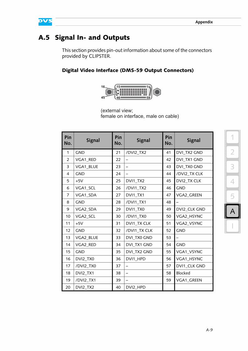
A-9
2
1
3
4
5
Appendix
I
A
A.5 Signal In- and Outputs
This section provides pin-out information about some of the connectors provided by CLIPSTER.
Digital Video Interface (DMS-59 Output Connectors)
Pin No.
SignalPin No.
SignalPin No.
Signal
1 GND 21 /DVI2_TX2 41 DVI_TX2 GND
2 VGA1_RED 22 – 42 DVI_TX1 GND
3 VGA1_BLUE 23 – 43 DVI_TX0 GND
4 GND 24 – 44 /DVI2_TX CLK
5 +5V 25 DVI1_TX2 45 DVI2_TX CLK
6 VGA1_SCL 26 /DVI1_TX2 46 GND
7 VGA1_SDA 27 DVI1_TX1 47 VGA2_GREEN
8 GND 28 /DVI1_TX1 48 –
9 VGA2_SDA 29 DVI1_TX0 49 DVI2_CLK GND
10 VGA2_SCL 30 /DVI1_TX0 50 VGA2_HSYNC
11 +5V 31 DVI1_TX CLK 51 VGA2_VSYNC
12 GND 32 /DVI1_TX CLK 52 GND
13 VGA2_BLUE 33 DVI_TX0 GND 53 –
14 VGA2_RED 34 DVI_TX1 GND 54 GND
15 GND 35 DVI_TX2 GND 55 VGA1_VSYNC
16 DVI2_TX0 36 DVI1_HPD 56 VGA1_HSYNC
17 /DVI2_TX0 37 – 57 DVI1_CLK GND
18 DVI2_TX1 38 – 58 Blocked
19 /DVI2_TX1 39 – 59 VGA1_GREEN
20 DVI2_TX2 40 DVI2_HPD
(external view;female on interface, male on cable)
115
5946
16
45
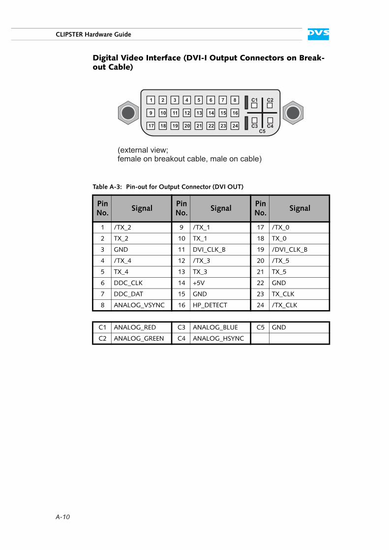
A-10
CLIPSTER Hardware Guide
Digital Video Interface (DVI-I Output Connectors on Break-out Cable)
Table A-3: Pin-out for Output Connector (DVI OUT)
Pin No.
SignalPin No.
SignalPin No.
Signal
1 /TX_2 9 /TX_1 17 /TX_0
2 TX_2 10 TX_1 18 TX_0
3 GND 11 DVI_CLK_B 19 /DVI_CLK_B
4 /TX_4 12 /TX_3 20 /TX_5
5 TX_4 13 TX_3 21 TX_5
6 DDC_CLK 14 +5V 22 GND
7 DDC_DAT 15 GND 23 TX_CLK
8 ANALOG_VSYNC 16 HP_DETECT 24 /TX_CLK
C1 ANALOG_RED C3 ANALOG_BLUE C5 GND
C2 ANALOG_GREEN C4 ANALOG_HSYNC
(external view;female on breakout cable, male on cable)
1
9
17
3
11
19
2
10
18
4
12
20
8
16
24
C1 C2
C4C3C5
7
15
23
6
14
22
5
13
21
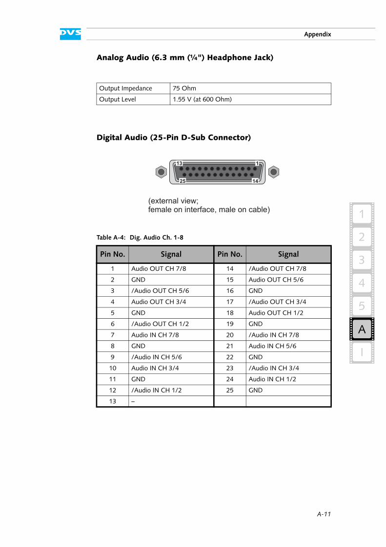
A-11
2
1
3
4
5
Appendix
I
A
Analog Audio (6.3 mm (¼") Headphone Jack)
Digital Audio (25-Pin D-Sub Connector)
Output Impedance 75 Ohm
Output Level 1.55 V (at 600 Ohm)
Table A-4: Dig. Audio Ch. 1-8
Pin No. Signal Pin No. Signal
1 Audio OUT CH 7/8 14 /Audio OUT CH 7/8
2 GND 15 Audio OUT CH 5/6
3 /Audio OUT CH 5/6 16 GND
4 Audio OUT CH 3/4 17 /Audio OUT CH 3/4
5 GND 18 Audio OUT CH 1/2
6 /Audio OUT CH 1/2 19 GND
7 Audio IN CH 7/8 20 /Audio IN CH 7/8
8 GND 21 Audio IN CH 5/6
9 /Audio IN CH 5/6 22 GND
10 Audio IN CH 3/4 23 /Audio IN CH 3/4
11 GND 24 Audio IN CH 1/2
12 /Audio IN CH 1/2 25 GND
13 –
(external view;female on interface, male on cable)
113
25 14

A-12
CLIPSTER Hardware Guide
SATA (External SATA (eSATA) Connector)
Table A-5: Dig. Audio Ch. 9-16
Pin No. Signal Pin No. Signal
1 Audio OUT CH 15/16 14 /Audio OUT CH 15/16
2 GND 15 Audio OUT CH 13/14
3 /Audio OUT CH 13/14 16 GND
4 Audio OUT CH 11/12 17 /Audio OUT CH 11/12
5 GND 18 Audio OUT CH 9/10
6 /Audio OUT CH 9/10 19 GND
7 Audio IN CH 15/16 20 /Audio IN CH 15/16
8 GND 21 Audio IN CH 13/14
9 /Audio IN CH 13/14 22 GND
10 Audio IN CH 11/12 23 /Audio IN CH 11/12
11 GND 24 Audio IN CH 9/10
12 /Audio IN CH 9/10 25 GND
13 –
Pin No. Signal Pin No. Signal
1 GND 5 RX
2 TX 6 /RX
3 /TX 7 GND
4 GND
71
(external view;female on interface, male on cable)
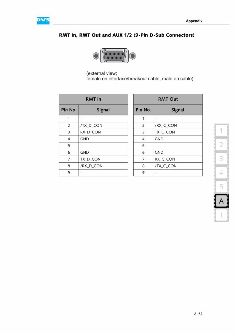
A-13
2
1
3
4
5
Appendix
I
A
RMT In, RMT Out and AUX 1/2 (9-Pin D-Sub Connectors)
RMT In RMT Out
Pin No. Signal Pin No. Signal
1 – 1 –
2 /TX_D_CON 2 /RX_C_CON
3 RX_D_CON 3 TX_C_CON
4 GND 4 GND
5 – 5 –
6 GND 6 GND
7 TX_D_CON 7 RX_C_CON
8 /RX_D_CON 8 /TX_C_CON
9 – 9 –
5
9
1
6
(external view;female on interface/breakout cable, male on cable)
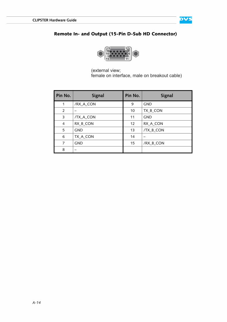
A-14
CLIPSTER Hardware Guide
Remote In- and Output (15-Pin D-Sub HD Connector)
Pin No. Signal Pin No. Signal
1 /RX_A_CON 9 GND
2 – 10 TX_B_CON
3 /TX_A_CON 11 GND
4 RX_B_CON 12 RX_A_CON
5 GND 13 /TX_B_CON
6 TX_A_CON 14 –
7 GND 15 /RX_B_CON
8 –
(external view;female on interface, male on breakout cable)
5
10
15 11
1
6
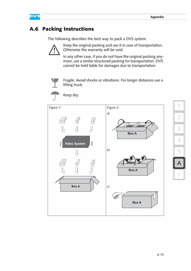
A-15
2
1
3
4
5
Appendix
I
A
A.6 Packing Instructions
The following describes the best way to pack a DVS system.
Keep the original packing and use it in case of transportation. Otherwise the warranty will be void.
In any other case, if you do not have the original packing any-more, use a similar structured packing for transportation. DVS cannot be held liable for damages due to transportation.
Fragile. Avoid shocks or vibrations. For longer distances use a lifting truck.
Keep dry.
Figure 1: Figure 2:
a)
b)
c)
Video System
Fro
nt
Rear
Box A
Box A
Box A
Box A
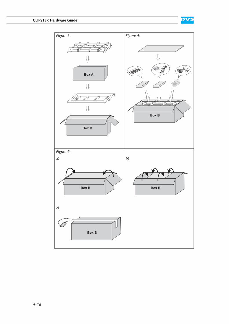
A-16
CLIPSTER Hardware Guide
Figure 3: Figure 4:
Figure 5:
a) b)
c)
Box A
Box B
Box B
Box B Box B
Box B
A-17
2
1
3
4
5
Appendix
I
A
A.7 Conformity Declarations
CLIPSTER has been tested according to the applying national and inter-national directives and regulations. The following states further infor-mation about the compliances and conformities.
A.7.1 RoHS Compliance
The EU directive 2002/95/EC ’Restriction of Hazardous Substances (RoHS)’ prohibits the use of certain substances in electrical and elec-tronic equipment. The CLIPSTER devices are manufactured in compli-ance with this directive.
A.7.2 EC Declaration of Conformity (CE Marking)
DVS Digital Video Systems AG herewith declares that the following product(s) according to the provisions of the mentioned EC Directives – including their relevant revisions at the time of this declaration – is (are) in conformity with the detailed standards or other normative docu-ments:
CLIPSTER EC Directives:
– EMC Directive 89/336/EEC– Low-Voltage Directive 73/23/EEC
Applied Harmonized Standards:
– EN50081-1– EN50082-1– EN55022– EN55024– EN61000-3-2– EN61000-3-3– IEC61000-4-2– IEC61000-4-3– IEC61000-4-4– IEC61000-4-5– IEC61000-4-6– IEC61000-4-11
A-18
CLIPSTER Hardware Guide
A.7.3 FCC Compliance Statement
DVS Digital Video Systems AG herewith declares that the following equipment has been tested according to the applying valid FCC regu-lations:
– CLIPSTER
FCC Notice
This equipment has been tested and found to comply with the limits for a Class A digital device, pursuant to Part 15 of the FCC Rules. These limits are designed to provide reasonable protection against harmful in-terference when the equipment is operated in a commercial environ-ment. This equipment generates, uses, and can radiate radio frequency energy and, if not installed and used in accordance with the instruction manual, may cause harmful interference to radio communications. Op-eration of this equipment in a residential area is likely to cause harmful interference in which case the user will be required to correct the inter-ference at his own expense.
Note: Connecting this device to peripheral devices that do not comply with Class A requirements or using an unshielded peripheral data cable could also result in harmful interference to radio or television reception. The user is cautioned that any changes or modifications not expressly approved by the party responsible for compliance could void the user’s authority to operate this equipment. To ensure that the use of this prod-uct does not contribute to interference, it is necessary to use shielded I/O cables.
I-1
2
1
3
4
5
I
A
IIndex
Numerics
15-pin D-Sub connector pin-out ....A-1425-pin D-Sub connector pin-out ....A-113-Gbit/s SDI .......................2-13, 2-164K .......................................1-2, 2-129-pin D-Sub connector pin-out
AUX 1/2 ................................A-13RMT In/Out ...........................A-13
A-C
accessing the hard disk array ........... 2-7activity of hard disks ........ 2-3, 2-5, 2-9alarm .............................2-5, A-2, A-3
fan .......................................... 5-7hard disk failure ................ 5-3, A-3LED .................. 2-4, 5-7, A-2, A-3overheating .............................A-2RAID controller ................. 5-3, A-3
Analog Audio OutMon. 1 .................................. 2-14Mon. 2 .................................. 2-14specifications ..........................A-11
ATX connector panel ...........2-11, 2-17audio ............................................ 1-1
analog audio ................ 2-14, A-11digital (AES/EBU) ...........2-14, 2-15pin-out ..................................A-11XLR connectors .............2-14, 2-15
AUX 1 ......................................... 2-17pin-out ..................................A-13
AUX 1-2 ..................................... 2-15AUX 2 ......................................... 2-17
pin-out ..................................A-13B/Pb Out .................................... 2-16BIOS ............................................. 1-9breakout cable
digital audio ..................2-14, 2-15
DVI .......................................2-19camera ..........................................1-1casing
close ........................................5-6open ........................................5-6
chapter overview ............................1-3CLIPSTER
installation ...............................3-1main storage ............................2-8options ....................................1-1shut down ................................4-2specifications ............................A-6start ........................................4-1storage capacity ......... 1-1, 1-9, 2-2technical data ...........................A-4variants ....................................2-2video raster ..............................A-8
closing of casing .............................5-6color modes .................................2-13COM port ...................................2-18composite sync .............................2-16conformity declaration .......... 1-8, A-17connectors ...................................2-11
ATX connector panel ......2-11, 2-17DVI .......................................2-20labeling ..................................2-12main connector panel .....2-11, 2-14naming conventions ................2-12slot panels .....................2-12, 2-18USB .........................................2-5
conventionsnaming of connectors ..............2-12typographical ...........................1-5
D-F
data loss ........................................2-8data protection ...............................5-2DB-15 connector ..........................A-14
I-2
CLIPSTER Hardware Guide
DB-25 connector ..........................A-11DB-9 connector
AUX 1/2 ................................A-13RMT In ..................................A-13RMT Out ...............................A-13
declaration of conformity ...... 1-8, A-17Digital Audio
Ch. 1-8 ........................ 2-14, A-11Ch. 9-16 ...................... 2-15, A-12
dimensions ....................................A-5disk activity LED
disk carrier ............................... 2-9HDD LEDs ............................... 2-5
disk carrier ...................... 2-8, 2-9, 5-4overview .................................. 2-8
disk power LED (disk carrier) ............ 2-9disk set (RAID) ............................... 5-2DMS-59 connector ....................... 2-19
pin-out ....................................A-9dual link ................... 2-12, 2-15, 2-16DVD drive ..................................... 2-9
eject ........................................ 2-9emergency eject ..................... 2-10tray ......................................... 2-9
DVI connector ............................. 2-19breakout cable ........................ 2-19DVI A/B ................................. 2-20DVI C/D ................................ 2-20pin-out ..........................A-9, A-10
DVI In ......................................... 2-17DVI Out pin-out ...........................A-10DVI out pin-out .............................A-9DVS logo (faceplate) ................2-5, 2-7eject (DVD drive) ........................... 2-9emergency eject (DVD drive) ......... 2-10environmental conditions ........ 1-7, A-4eSATA .............................. 2-17, A-12Ethernet ...................................... 2-18external SATA connector ............... 2-17
pin-out ..................................A-12faceplate ....................................... 2-7
DVS logo ..........................2-5, 2-7lift ........................................... 2-7removal ................................. 5-12
fan failure ...................................... 5-7fan module .................................... 5-8fast shut down ............................... 4-2Fibre Channel ................................ 1-2front overview ............................... 2-2
G-I
G/Y Out ......................................2-16graphic card .................................2-19guarantee ......................................1-8handle .........................................2-21hard disk array ....................... 2-3, 2-8
access ......................................2-7hard disk(s) ....................................2-8
activity ...................... 2-3, 2-5, 2-9assembly ..................................5-5disk power LED .........................2-9disk set ....................................5-2failure .............................. 5-2, 5-3rebuilding failed disk ..................5-5removal ...................................5-4replace .....................................5-4status ........................ 2-3, 2-5, 2-9
hardware variants ...........................2-2hinge .................................. 2-7, 5-12horizontal sync .............................2-16important notes ...................... 1-8, 1-9installation .....................................3-1instructions
installation ................................3-1maintenance .............................5-1operation .................................4-1packing ................................. A-15safety ......................................1-6
J-L
keyboard ............................. 2-18, 3-1labeling of connectors ...................2-12LAN .................................... 2-4, 2-18latch ............................................2-22LEDs
alarm ................2-4, 5-7, A-2, A-3disk activity ...................... 2-5, 2-9disk power ...............................2-9HDD ................................ 2-5, 2-9LAN .........................................2-4power supply ................ 2-21, 5-10system HDD .............................2-4
lever (disk carrier) ...........................2-9LTC
In ..........................................2-14Out .......................................2-14
M-O
magnets ........................................2-7
I-3
Index
2
1
3
4
5
I
A
main connector panel ..........2-11, 2-14main storage .................................. 2-8mirroring of ports ......................... 2-12mixer control ......................2-15, 2-17monitor ................................2-19, 3-1mouse ..................................2-17, 3-1multi-device .................................. 1-2mute button ..2-5, 5-7, 5-10, A-2, A-3naming conventions (connectors) ... 2-12network ...................................... 2-18
connection ......................2-4, 2-18connection status ...................... 2-4
notes (important) ....................1-8, 1-9opener (disk carrier) ........................ 2-9opening of casing ........................... 5-6operation items .............................. 2-4options ......................................... 1-1
10GE ....................................... 1-212Bit ....................................... 1-33D LUT and Color Management . 1-24K Workflow ........................... 1-2Additional Operators ................. 1-3Color Correction Panel .............. 1-3DCI Mastering .......................... 1-2DDR ........................................ 1-3Disk-Upgrade ........................... 1-2Disk-Upgrades ......................... 1-1DVI Output 16 Bit Cinevator ...... 1-2FC/SAN ................................... 1-2InfiniBand ................................ 1-2JPEG2000 Processor .................. 1-2Multi-Device ............................ 1-2Raster ...................................... 1-3Remote Zoom & Pan ................. 1-2Secondary Color Correction ....... 1-3Special Raster Formats ............... 1-3Teletext VBI 335 ....................... 1-2
overheating ...................................A-2overview ....................................... 2-1
chapters .................................. 1-3connectors ............................. 2-11disk carrier ............................... 2-8front ....................................... 2-2power supply unit ................... 2-21rear ....................................... 2-11
P-R
packing instructions ......................A-15parallel port ................................. 2-17parity information (RAID) .........5-2, 5-3pin-out
15-pin D-Sub connector ..........A-1425-pin D-Sub connector ..........A-119-pin D-Sub connector ............A-13audio .....................................A-11AUX 1/2 ................................A-13DMS-59 connector ....................A-9DVI Out .................................A-10DVI out ...................................A-9RMT In ..................................A-13RMT Out ...............................A-13SATA (eSATA) ........................A-12
power ...........................................2-5on/off status ............................2-7switch ...............................2-5, 4-1
power cable socket .......................2-22power supply ...............................2-12
handle ...................................2-21latch ......................................2-22LED .......................................2-21overview of one unit ...............2-21power cable socket ..................2-22status of unit ..........................2-21unit failure .............................5-10
power switch ..........................2-5, 4-1quad HD-SDI ...............................2-16R/Pr Out .....................................2-16RAID ......................................2-8, 5-2
controllers ................................5-2disk set ....................................5-2parity information ..............5-2, 5-3RAID 5 ....................................5-2rebuilding failed disk ..................5-5
real-time capability .........................2-2rear overview ...............................2-11rebuilding failed disk .......................5-5REF In .........................................2-16reference input .............................2-16remote control .............................2-14
pin-out 15-pin D-Sub ..............A-14pin-out 9-pin D-Sub ................A-13
removal of the faceplate ................5-12reset button ...................................2-5RMT In ........................................2-15
pin-out ..................................A-13RMT Out .....................................2-15
pin-out ..................................A-13RS-232 ........................................2-18RS-422 ........................................2-14
S-T
safety instructions ...........................1-6
I-4
CLIPSTER Hardware Guide
SATA .......................................... 2-17cable length ........................... 2-17pin-out ..................................A-12
SD/HD-SDI In 1/A ....................... 2-15SD/HD-SDI In 2/B ........................ 2-15SD/HD-SDI In 3/C ....................... 2-15SD/HD-SDI In 4 ........................... 2-15SD/HD-SDI In 5 - 8 ...................... 2-17SD/HD-SDI Out 1/A ..................... 2-16SD/HD-SDI Out 2/B ..................... 2-16SD/HD-SDI Out 3/C ..................... 2-16SD/HD-SDI Out 4 ........................ 2-16SD/HD-SDI Out 5 - 8 ................... 2-16SDI (serial digital interface) ..2-14, 2-15,
2-163-Gbit/s SDI ..................2-13, 2-16quad HD-SDI ......................... 2-16signal distribution .................... 2-13
SD-SDI Out 1 .............................. 2-15SD-SDI Out 2 .............................. 2-15shutting down ............................... 4-2
fast shut down ......................... 4-2signal distribution (SDI) ................. 2-13single link ................. 2-12, 2-15, 2-16slot panel connectors ...........2-12, 2-18specification(s) ...............................A-6
analog audio ..........................A-11starting ......................................... 4-1status
of disk power ........................... 2-9of hard disks .............. 2-3, 2-5, 2-9
of network connection ...............2-4of power supply unit ...............2-21of power-on/-off ......................2-7
storage capacity .............. 1-1, 1-9, 2-2stripe set ........................................5-2Sync Out .....................................2-16system HDD ...................................2-8
LED .........................................2-4system reset ...................................2-5target group ...................................1-5technical data ................................ A-4
dimensions .............................. A-5general ................................... A-4
telecine ..........................................1-1transportation ...................... 1-7, A-15tray (DVD drive) .............................2-9troubleshooting ............................. A-2typographical conventions ...............1-5
U-Z
USB connectors .................... 2-5, 2-18variants .........................................2-2video I/O panel ............................2-19video raster ................................... A-8video workstation ...........................1-1VTR ..............................................1-1warranty ........................................1-8WClk Out ....................................2-16XLR connectors (audio) ....... 2-14, 2-15


![Allochtonen, Politiek & Internet 3.0 [API 3.0]](https://img.dokumen.tips/doc/110x75/55a86f3a1a28abb4778b45f1/allochtonen-politiek-internet-30-api-30.jpg)
![LWMIRROR2 3.0-H-004[A0]MIRROR2 3.0](https://img.dokumen.tips/doc/110x75/55cf9256550346f57b95a1b3/lwmirror2-30-h-004a0mirror2-30.jpg)


![Migrants, Politics & Internet 3.0 [API 3.0]](https://img.dokumen.tips/doc/110x75/55b471f6bb61eba2148b46e2/migrants-politics-internet-30-api-30.jpg)