Embed Size (px)
Citation preview

Clinical Testing on External Ventricular DrainageGuidance using Mixed RealityShin-Yan Chiou
Chang Gung UniversityZhi-Yue Zhang
Chang Gung UniversityHao-Li Liu
National Taiwan UniversityJiun-Lin Yan
Keelung Chang Gung Memorial HospitalKuo-Chen Wei
Chang Gung Memorial HospitalPin-Yuan Chen ( [email protected] )
Keelung Chang Gung Memorial Hospital
Research Article
Keywords: Surgical navigation, Mixed reality, Augmented reality, Neurosurgery
Posted Date: September 27th, 2021
DOI: https://doi.org/10.21203/rs.3.rs-900327/v1
License: This work is licensed under a Creative Commons Attribution 4.0 International License. Read Full License

1
Clinical testing on external ventricular drainage
guidance using mixed reality
Shin-Yan Chiou1,2,3, Zhi-Yue Zhang1, Hao-Li Liu4, Jiun-Lin Yan3, Kuo-Chen Wei5,6,7, and Pin-Yuan Chen3,7,* 1Department of Electrical Engineering, College of Engineering, Chang Gung University, Tao-Yuan, Taiwan, 2Department of Nuclear Medicine, Linkou Chang Gung Memorial Hospital, Tao-Yuan, Taiwan 3Department of Neurosurgery, Keelung Chang Gung Memorial Hospital, Tao-Yuan, Taiwan 4Department of Electrical Engineering, National Taiwan University, Taipei, Taiwan 5Department of Neurosurgery, Chang Gung Memorial Hospital, Linkou Medical Center, Taoyuan, Taiwan 6Department of Neurosurgery, New Taipei Municipal TuCheng Hospital, New Taipei City, Taiwan 7School of Medicine, Chang Gung University, Tao-Yuan, Taiwan
Corresponding author: Pin-Yuan Chen (e-mail: [email protected]).
The authors are grateful to the Neuroscience Research Center of Chang Gung Memorial Hospital, Linkou, Taiwan. This work is partially supported by the Ministry of Science and Technology under Grant MOST 109-2221-E-182-020, by the National Health Research Institutes under Grant NHRI-EX110-10502NI, and by the CGMH project under Grant BMRPB46.
ABSTRACT Augmented reality surgery systems have played an important role in assisting physicians in their operations. However, applying the system to brain neurosurgery is challenging. In addition to using the augmented reality technology to display the 3D position of the surgical target position in real time, we also need to consider the display of the scalpel entry point and scalpel orientation, and their accurate superposition on patients. This paper proposes a mixed reality surgical navigation system, which accurately superimposes the surgical target position, scalpel entry point and scalpel direction on a patient's head and displays it on a tablet, facilitating the visual and intuitive way for the brain neurosurgery. Based on the current neurosurgery navigation system, we integrated mixed reality technology on it. We first independently tested the accuracy of the optical measurement system - NDI Polaris Vicra, and then designed functions that a physician can quickly point out the surgical target position and decide an entry point position, and a tablet can display the superimposed images of surgical target, entry point, and scalpel, and perform the correctness of scalpel orientation. Then we used the Dicom of the patient CT to create a phantom and it’s AR model, imported this AR model into the APP, and installed and executed the APP on the tablet. In the preoperative phase, the technician first superimposed the AR image of head and the scalpel in 5-7 minutes, and then the physician point out and set the target position and entry point position in 2 minutes on a tablet, which then dynamically displayed the superimposed image of the head, target position, entry point position, and scalpel (including the scalpel tip and scalpel spatial direction). We successfully conducted multiple experiments on phantom and six experiments on clinical neurosurgical EVD practice. In the 2D-plane-superposition model (n = 60), the optical measurement system (NDI Polaris Vicra) was feasible of the visualization space with high accuracy (mean error ± standard deviation (SD): 2.013 ± 1.118 mm). In the clinical trials in the hospital (n = 4), the average technician preparation time was 6.317 minutes. The average time (n = 4) required for the physician to set the target position and the entry-point position and accurately overlay the orientation with a surgical stick was 3.5 minutes. In the preparation phase, the average time required for the Dicom image processing and program importing was 120 ± 30 minutes. The designed mixed reality optical surgical navigation system can successfully achieve clinical accuracy, and guide physicians to perform brain surgery visually and intuitively. In addition, the physician can use the APP of the tablet device to instantly obtain Dicom images with the designated patient, change the position of the surgical entry point, and instantly obtain the accurate surgical path and surgical angle after the modification. This design can be used as the basis for various AR or MR brain surgery navigation systems in the future.
INDEX TERMS Surgical navigation, Mixed reality, Augmented reality, Neurosurgery
2
I. INTRODUCTION
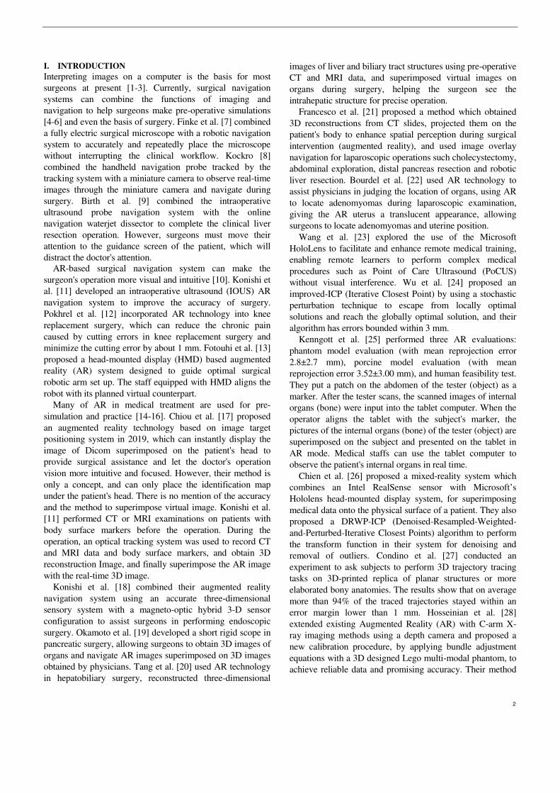
Interpreting images on a computer is the basis for most surgeons at present [1-3]. Currently, surgical navigation systems can combine the functions of imaging and navigation to help surgeons make pre-operative simulations [4-6] and even the basis of surgery. Finke et al. [7] combined a fully electric surgical microscope with a robotic navigation system to accurately and repeatedly place the microscope without interrupting the clinical workflow. Kockro [8] combined the handheld navigation probe tracked by the tracking system with a miniature camera to observe real-time images through the miniature camera and navigate during surgery. Birth et al. [9] combined the intraoperative ultrasound probe navigation system with the online navigation waterjet dissector to complete the clinical liver resection operation. However, surgeons must move their attention to the guidance screen of the patient, which will distract the doctor's attention.
AR-based surgical navigation system can make the surgeon's operation more visual and intuitive [10]. Konishi et al. [11] developed an intraoperative ultrasound (IOUS) AR navigation system to improve the accuracy of surgery. Pokhrel et al. [12] incorporated AR technology into knee replacement surgery, which can reduce the chronic pain caused by cutting errors in knee replacement surgery and minimize the cutting error by about 1 mm. Fotouhi et al. [13] proposed a head-mounted display (HMD) based augmented reality (AR) system designed to guide optimal surgical robotic arm set up. The staff equipped with HMD aligns the robot with its planned virtual counterpart.
Many of AR in medical treatment are used for pre-simulation and practice [14-16]. Chiou et al. [17] proposed an augmented reality technology based on image target positioning system in 2019, which can instantly display the image of Dicom superimposed on the patient's head to provide surgical assistance and let the doctor's operation vision more intuitive and focused. However, their method is only a concept, and can only place the identification map under the patient's head. There is no mention of the accuracy and the method to superimpose virtual image. Konishi et al. [11] performed CT or MRI examinations on patients with body surface markers before the operation. During the operation, an optical tracking system was used to record CT and MRI data and body surface markers, and obtain 3D reconstruction Image, and finally superimpose the AR image with the real-time 3D image.
Konishi et al. [18] combined their augmented reality navigation system using an accurate three-dimensional sensory system with a magneto-optic hybrid 3-D sensor configuration to assist surgeons in performing endoscopic surgery. Okamoto et al. [19] developed a short rigid scope in pancreatic surgery, allowing surgeons to obtain 3D images of organs and navigate AR images superimposed on 3D images obtained by physicians. Tang et al. [20] used AR technology in hepatobiliary surgery, reconstructed three-dimensional
images of liver and biliary tract structures using pre-operative CT and MRI data, and superimposed virtual images on organs during surgery, helping the surgeon see the intrahepatic structure for precise operation.
Francesco et al. [21] proposed a method which obtained 3D reconstructions from CT slides, projected them on the patient's body to enhance spatial perception during surgical intervention (augmented reality), and used image overlay navigation for laparoscopic operations such cholecystectomy, abdominal exploration, distal pancreas resection and robotic liver resection. Bourdel et al. [22] used AR technology to assist physicians in judging the location of organs, using AR to locate adenomyomas during laparoscopic examination, giving the AR uterus a translucent appearance, allowing surgeons to locate adenomyomas and uterine position.
Wang et al. [23] explored the use of the Microsoft HoloLens to facilitate and enhance remote medical training, enabling remote learners to perform complex medical procedures such as Point of Care Ultrasound (PoCUS) without visual interference. Wu et al. [24] proposed an improved-ICP (Iterative Closest Point) by using a stochastic perturbation technique to escape from locally optimal solutions and reach the globally optimal solution, and their algorithm has errors bounded within 3 mm.
Kenngott et al. [25] performed three AR evaluations: phantom model evaluation (with mean reprojection error 2.8±2.7 mm), porcine model evaluation (with mean reprojection error 3.52±3.00 mm), and human feasibility test. They put a patch on the abdomen of the tester (object) as a marker. After the tester scans, the scanned images of internal organs (bone) were input into the tablet computer. When the operator aligns the tablet with the subject's marker, the pictures of the internal organs (bone) of the tester (object) are superimposed on the subject and presented on the tablet in AR mode. Medical staffs can use the tablet computer to observe the patient's internal organs in real time.
Chien et al. [26] proposed a mixed-reality system which combines an Intel RealSense sensor with Microsoft’s Hololens head-mounted display system, for superimposing medical data onto the physical surface of a patient. They also proposed a DRWP-ICP (Denoised-Resampled-Weighted-and-Perturbed-Iterative Closest Points) algorithm to perform the transform function in their system for denoising and removal of outliers. Condino et al. [27] conducted an experiment to ask subjects to perform 3D trajectory tracing tasks on 3D-printed replica of planar structures or more elaborated bony anatomies. The results show that on average more than 94% of the traced trajectories stayed within an error margin lower than 1 mm. Hosseinian et al. [28] extended existing Augmented Reality (AR) with C-arm X-ray imaging methods using a depth camera and proposed a new calibration procedure, by applying bundle adjustment equations with a 3D designed Lego multi-modal phantom, to achieve reliable data and promising accuracy. Their method
3
can visualize X-ray images opon 3D data with an average overlay error of 1.03 mm.
However, most AR surgical navigation methods are not applied to brain surgery. Zeng et al. [29] proposed a prototype system that uses SEEG to realize Video see-through augmented reality (VAR) and Spatial augmented reality (SAR) in 2017. This system can help surgeons quickly and intuitively confirm registration accuracy, locate entry points, and visualize internal anatomy in virtual image space and actual patient space. They also designed and developed a projector-camera system for the robot arm.
Léger et al. [30] studied the effects of two different types of AR IGS (mobile AR and desktop AR) and traditional surgical navigation on the transfer of concentration in craniotomy in 2017. They found that AR IGS surgery is very different from traditional surgery in terms of the time it takes to perform work and focus transfer. There is not much difference between different types of AR IGS. Users feel that the mobile AR system is easier to use and the effect is better. These results point out that for surgeons, no matter where these AR images are displayed, AR may be able to reduce the diversion of attention and get more optimized and more focused surgical procedures.
Besharati Tabrizi and Mehran [31] in 2015 proposed a method of using an image projector to create augmented reality. By projecting the patient's skull image on the patient's head in reality, the function of surgical navigation is achieved. However, this method lacks the function of displaying the relative position of the scalpel in the augmented reality, and also cannot display the detailed brain tissue structure and the corresponding position and angle of the CT image.
Hou et al. [32] proposed a method to achieve augmented reality surgical navigation using a low-cost iPhone. However, it is not convenient to use iPhone as a surgical navigation tool during surgery. In addition, this method can only provide augmented reality images at a specific angle, which further limits its convenience. Zhang et al. [33] developed a surgical Google Glass navigation system using near-infrared fluorescence and ultrasound images. With this system, fluorescence and ultrasound images can be automatically switched and displayed on Google Glass, clearly showing the tumor boundary that is invisible to the naked eye to facilitate the surgeon's operation. However, the current system still has some shortcomings and limitations. For example, Google Glass has (1) battery problem, (2) overheating, (3) limited field of view, and (4) focal length limitation. Another limitation in the operation is that the ICG used in fluorescent imaging is not a tumor-specific contrast agent, so it cannot be used in tumor-specific clinical applications.
However, these methods do not have a comprehensive solution for the surgical target, scalpel entry point, and scalpel orientation of brain surgery. Therefore, we propose an AR-based optical surgical navigation system to achieve AR brain neurosurgery navigation.
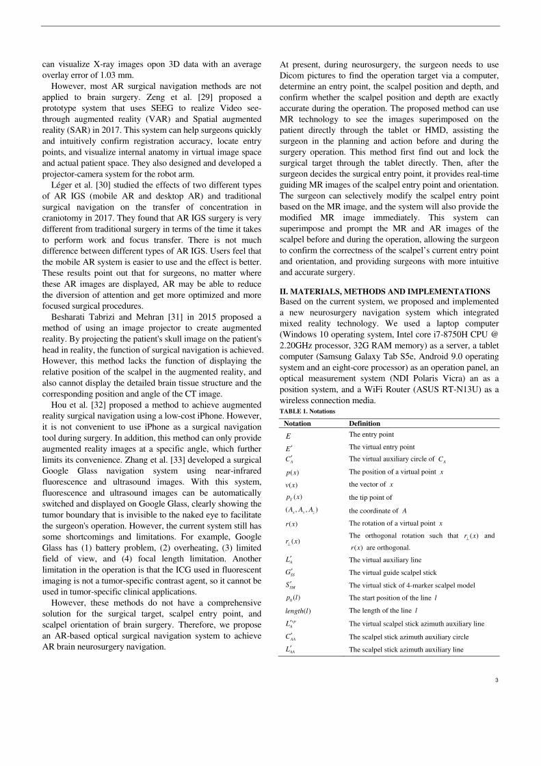
At present, during neurosurgery, the surgeon needs to use Dicom pictures to find the operation target via a computer, determine an entry point, the scalpel position and depth, and confirm whether the scalpel position and depth are exactly accurate during the operation. The proposed method can use MR technology to see the images superimposed on the patient directly through the tablet or HMD, assisting the surgeon in the planning and action before and during the surgery operation. This method first find out and lock the surgical target through the tablet directly. Then, after the surgeon decides the surgical entry point, it provides real-time guiding MR images of the scalpel entry point and orientation. The surgeon can selectively modify the scalpel entry point based on the MR image, and the system will also provide the modified MR image immediately. This system can superimpose and prompt the MR and AR images of the scalpel before and during the operation, allowing the surgeon to confirm the correctness of the scalpel’s current entry point and orientation, and providing surgeons with more intuitive and accurate surgery.
II. MATERIALS, METHODS AND IMPLEMENTATIONS
Based on the current system, we proposed and implemented a new neurosurgery navigation system which integrated mixed reality technology. We used a laptop computer (Windows 10 operating system, Intel core i7-8750H CPU @ 2.20GHz processor, 32G RAM memory) as a server, a tablet computer (Samsung Galaxy Tab S5e, Android 9.0 operating system and an eight-core processor) as an operation panel, an optical measurement system (NDI Polaris Vicra) an as a position system, and a WiFi Router (ASUS RT-N13U) as a wireless connection media. TABLE 1. Notations
Notation Definition
E The entry point
E′ The virtual entry point
AC′ The virtual auxiliary circle of AC
( )p x The position of a virtual point x
( )v x the vector of x
( )Tp x the tip point of
( , , )x y zA A A the coordinate of A
( )r x The rotation of a virtual point x
( )r x⊥
The orthogonal rotation such that ( )r x⊥
and
( )r x are orthogonal.
AL′ The virtual auxiliary line
SSG′ The virtual guide scalpel stick
SMS′ The virtual stick of 4-marker scalpel model
0 ( )p l The start position of the line l
( )length l The length of the line l vp
AL′ The virtual scalpel stick azimuth auxiliary line
AAC′ The scalpel stick azimuth auxiliary circle
AAL′ The scalpel stick azimuth auxiliary line
4
NDI Poloris Vicra
Laptop server
Patient
(Tablet image)
TabletWiFi router
Optical signal
2-3. Send physical scalpel
position information
Wir
ed tr
ansm
issi
on
1-1. Start MR superposition correction2-3. Physical scalpel position tracking
1-2. Send MR Superposition correction information2-5. Send physical scalpel position information
1-3. Virtual scalpel position correction2-6. Virtual scalpel position tracking3-1. Dicom number selection4-1. Target Position decision5-1. Entry Position decision6-1. Surgical path generation
1-5. Superimposing the virtual scalpel3-2. Presenting the selected Dicom4-2. Presenting Target Position5-2. Presenting Entry Position6-2. Presenting the surgical path
1-4. Superimposing the virtual scalpel2-7. Virtual scalpel position follows real scalpel
(2-1) Physical scalpel position information
4-marker probe
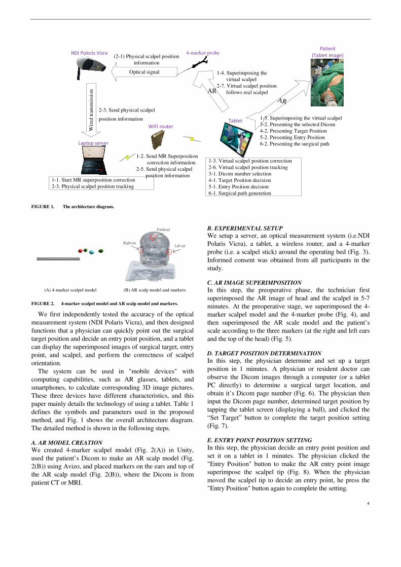
FIGURE 1. The architecture diagram.
Right ear
Forehead
Left ear
(A) 4-marker scalpel model (B) AR scalp model and markers
FIGURE 2. 4-marker scalpel model and AR scalp model and markers.
We first independently tested the accuracy of the optical measurement system (NDI Polaris Vicra), and then designed functions that a physician can quickly point out the surgical target position and decide an entry point position, and a tablet can display the superimposed images of surgical target, entry point, and scalpel, and perform the correctness of scalpel orientation.
The system can be used in "mobile devices" with computing capabilities, such as AR glasses, tablets, and smartphones, to calculate corresponding 3D image pictures. These three devices have different characteristics, and this paper mainly details the technology of using a tablet. Table 1 defines the symbols and parameters used in the proposed method, and Fig. 1 shows the overall architecture diagram. The detailed method is shown in the following steps.
A. AR MODEL CREATION
We created 4-marker scalpel model (Fig. 2(A)) in Unity, used the patient’s Dicom to make an AR scalp model (Fig. 2(B)) using Avizo, and placed markers on the ears and top of the AR scalp model (Fig. 2(B)), where the Dicom is from patient CT or MRI.
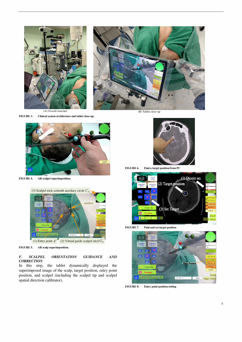
B. EXPERIMENTAL SETUP
We setup a server, an optical measurement system (i.e.NDI Polaris Vicra), a tablet, a wireless router, and a 4-marker probe (i.e. a scalpel stick) around the operating bed (Fig. 3). Informed consent was obtained from all participants in the study.
C. AR IMAGE SUPERIMPOSITION
In this step, the preoperative phase, the technician first superimposed the AR image of head and the scalpel in 5-7 minutes. At the preoperative stage, we superimposed the 4-marker scalpel model and the 4-marker probe (Fig. 4), and then superimposed the AR scale model and the patient’s scale according to the three markers (at the right and left ears and the top of the head) (Fig. 5).
D. TARGET POSITION DETERMINATION
In this step, the physician determine and set up a target position in 1 minutes. A physician or resident doctor can observe the Dicom images through a computer (or a tablet PC directly) to determine a surgical target location, and obtain it’s Dicom page number (Fig. 6). The physician then input the Dicom page number, determined target position by tapping the tablet screen (displaying a ball), and clicked the “Set Target” button to complete the target position setting (Fig. 7).
E. ENTRY POINT POSITION SETTING
In this step, the physician decide an entry point position and set it on a tablet in 1 minutes. The physician clicked the "Entry Position" button to make the AR entry point image superimpose the scalpel tip (Fig. 8). When the physician moved the scalpel tip to decide an entry point, he press the "Entry Position" button again to complete the setting.
5
(A) Overall structure
(B) Tablet close-up
FIGURE 3. Clinical system architecture and tablet close-up.
FIGURE 4. AR scalpel superimposition.
marker
(3) Scalpel stick azimuth auxiliary circle AAC′
(1) Entry point E′ (2) Virtual guide scalpel stick SSG′
FIGURE 5. AR scalp superimposition.
F. SCALPEL ORIENTATION GUIDANCE AND
CORRECTION
In this step, the tablet dynamically displayed the superimposed image of the scalp, target position, entry point position, and scalpel (including the scalpel tip and scalpel spatial direction calibrator).
FIGURE 6. Find a target position from PC
((((1111) ) ) ) Dicom noDicom noDicom noDicom no....
((((2222) ) ) ) Target positionTarget positionTarget positionTarget position
((((3333) ) ) ) Set TargetSet TargetSet TargetSet Target
123
88
FIGURE 7. Find and set target position
Entry PositionEntry PositionEntry PositionEntry Position
FIGURE 8. Entry point position setting

6
Extension lineExtension lineExtension lineExtension line
RedRedRedRed
(A) Extension line and red scalpel stick
YellowYellowYellowYellow
(B) Yellow scalpel stick
GreenGreenGreenGreen
(C) Green scalpel stick
FIGURE 9. Extension line and three-color scalpel stick
After setting the entry point position, the surgeon pressed
the "Extension line" button, and a red scalpel stick AR image, the virtual guide scalpel stick
SSG′ , appeared and
superimposed over the scalp as a scalpel path extension bar, guiding the surgeon the position and angle of the scalpel (Fig. 9(A)). The surgeon can fine-tune the position and angle of the scalpel according to the color of the scalpel stick AR image and the orientation calibrator (a green circle in the upper right corner.)
The color change rule of the scalpel stick AR image is shown in Table 2, where
TABLE 2. The color change rule of the scalpel stick AR image
( ( ), ( )) 2T SMd p S p E mm′ ′ ≤ ( ( ), ( )) 1.5o
SM Av S v L′ ′∠ ≤ Color
F F Red F T Red T F Yellow T T Green
2
2 2 1/2
( ( ), ( )) (( ( ) ( ) )
( ( ) ( ) ) ( ( ) ( ) ) )
T SM T SM x x
T SM y y T SM z z
d p S p E p S p E
p S p E p S p E
′ ′ ′ ′= − +
′ ′ ′ ′− + −, (1)
( ) ( )
( ( ), ( )) cos( )( ) ( )
SM A
SM A
SM A
v S v Lv S v L a
v S v L
′ ′⋅′ ′∠ =
′ ′⋅, (2)
E ′ , A
L′ and SM
S ′ stand for the virtual entry point, the virtual
auxiliary line and the virtual stick of 4-marker scalpel model (Fig. 2(A)), respectively, ( )p x and ( )v x mean the position
and the vector of x , ( )T
p x means the tip point of x , and
( , , )x y z
A A A means the coordinate of A .
If the distance between the tip position of the scalpel image and the actual entry point is less than 2 mm and the angle between the scalpel and the scalpel stick AR image is greater than 1.5 degrees, the scalpel image will turn yellow (Fig. 9(B)), indicating that the position of the scalpel tip is correct but the angle is incorrect. If the distance between the tip position of the scalpel image and the actual entry point is less than 2 mm and the angle between the scalpel and the scalpel stick AR image is less than 1.5 degrees, the scalpel image will turn green (Fig. 9(C)), indicating that the position of the scalpel tip is correct and the angle is also correct.
G. SCALPEL STICK AZIMUTH AUXILIARY CIRCLE
In the upper right corner of the UI, there is a scalpel stick azimuth auxiliary circle
AAC ′ , which can assist surgeons to
adjust the correct orientation of the surgical scalpel stick (Fig. 5). The surgeon can infer whether the angle of the real scalpel stick is consistent with the angle of the virtual guide scalpel stick according to the length and the angle of the line in the circle, and adjust the orientation in real time.
The shorter the length of this line (closer to a point), the smaller the angle difference. The line’s deviation direction stands for the real scalpel stick’s deviation direction. The technical steps of
AAC ′ creation are shown as follows.
The system first creates a virtual auxiliary circle A
C ′ inside
of Unity, sets its position ( )A
p C′ at the position of the virtual
entry point E ′ : ( ) ( )
Ap C p E′ ′← , (3)
and sets the rotation of A
C ′ be orthogonal to the virtual guide
scalpel stick SS
G′ :
( ) ( )A SS
r C r G⊥
′ ′← , (4)
where ( )p x and ( )r x stand for the position and rotation of
x , and ( )r x⊥
is an orthogonal rotation such that ( )r x⊥
and
( )r x are orthogonal.
7
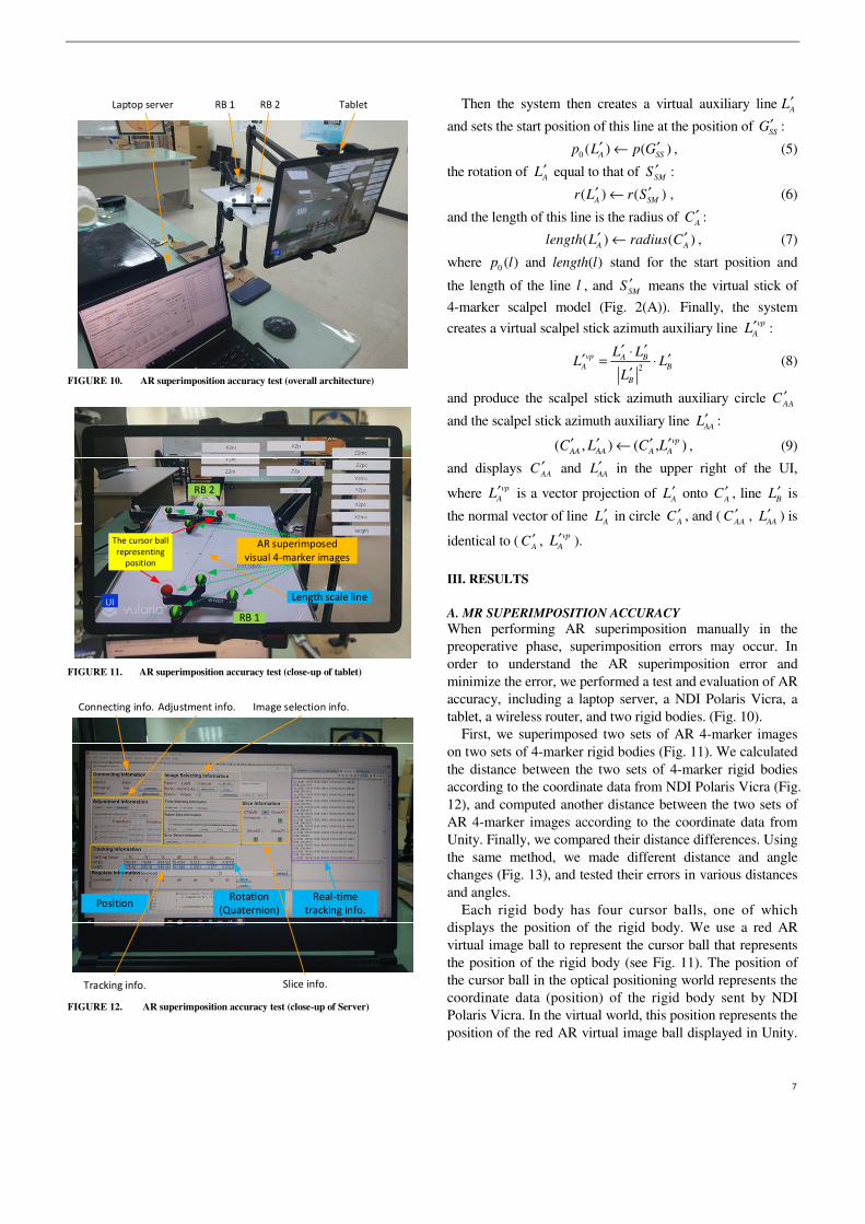
TabletRB 2RB 1Laptop server
FIGURE 10. AR superimposition accuracy test (overall architecture)
AR superimposed
visual 4-marker images
The cursor ball
representing
position
RB 1
RB 2
Length scale line
FIGURE 11. AR superimposition accuracy test (close-up of tablet)
PositionRotation
(Quaternion)
Tracking info.
Adjustment info.Connecting info. Image selection info.
Slice info.
Real-time
tracking info.
FIGURE 12. AR superimposition accuracy test (close-up of Server)
Then the system then creates a virtual auxiliary lineA
L′
and sets the start position of this line at the position of SS
G′ :
0 ( ) ( )A SS
p L p G′ ′← , (5)
the rotation of A
L′ equal to that of SM
S ′ :
( ) ( )A SM
r L r S′ ′← , (6)
and the length of this line is the radius of A
C ′ :
( ) ( )A A
length L radius C′ ′← , (7)
where 0 ( )p l and ( )length l stand for the start position and
the length of the line l , and SM
S ′ means the virtual stick of
4-marker scalpel model (Fig. 2(A)). Finally, the system
creates a virtual scalpel stick azimuth auxiliary line vp
AL′ :
2
vp A B
A B
B
L LL L
L
′ ′⋅′ ′= ⋅
′ (8)
and produce the scalpel stick azimuth auxiliary circle AA
C ′
and the scalpel stick azimuth auxiliary line AA
L′ :
( , ) ( , )vp
AA AA A AC L C L′ ′ ′ ′← , (9)
and displays AA
C ′ and AA
L′ in the upper right of the UI,
where vp
AL′ is a vector projection of A
L′ onto A
C ′ , line B
L′ is
the normal vector of line A
L′ in circle A
C ′ , and (AA
C ′ , AA
L′ ) is
identical to (A
C ′ , vp
AL′ ).
III. RESULTS
A. MR SUPERIMPOSITION ACCURACY
When performing AR superimposition manually in the preoperative phase, superimposition errors may occur. In order to understand the AR superimposition error and minimize the error, we performed a test and evaluation of AR accuracy, including a laptop server, a NDI Polaris Vicra, a tablet, a wireless router, and two rigid bodies. (Fig. 10).
First, we superimposed two sets of AR 4-marker images on two sets of 4-marker rigid bodies (Fig. 11). We calculated the distance between the two sets of 4-marker rigid bodies according to the coordinate data from NDI Polaris Vicra (Fig. 12), and computed another distance between the two sets of AR 4-marker images according to the coordinate data from Unity. Finally, we compared their distance differences. Using the same method, we made different distance and angle changes (Fig. 13), and tested their errors in various distances and angles.
Each rigid body has four cursor balls, one of which displays the position of the rigid body. We use a red AR virtual image ball to represent the cursor ball that represents the position of the rigid body (see Fig. 11). The position of the cursor ball in the optical positioning world represents the coordinate data (position) of the rigid body sent by NDI Polaris Vicra. In the virtual world, this position represents the position of the red AR virtual image ball displayed in Unity.
8
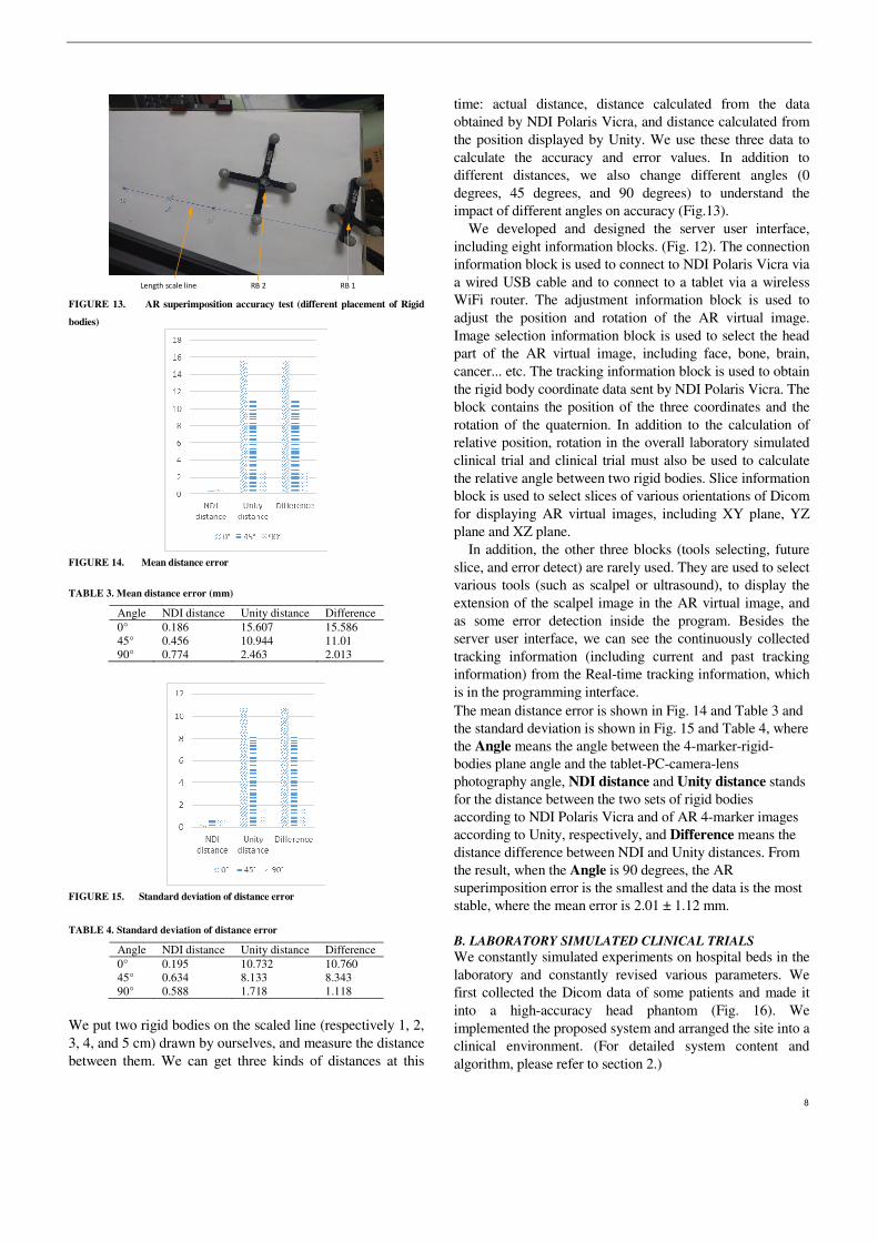
RB 1RB 2Length scale line FIGURE 13. AR superimposition accuracy test (different placement of Rigid
bodies)
FIGURE 14. Mean distance error
TABLE 3. Mean distance error (mm)
Angle NDI distance Unity distance Difference 0° 0.186 15.607 15.586 45° 0.456 10.944 11.01 90° 0.774 2.463 2.013
FIGURE 15. Standard deviation of distance error
TABLE 4. Standard deviation of distance error
Angle NDI distance Unity distance Difference 0° 0.195 10.732 10.760 45° 0.634 8.133 8.343 90° 0.588 1.718 1.118
We put two rigid bodies on the scaled line (respectively 1, 2, 3, 4, and 5 cm) drawn by ourselves, and measure the distance between them. We can get three kinds of distances at this
time: actual distance, distance calculated from the data obtained by NDI Polaris Vicra, and distance calculated from the position displayed by Unity. We use these three data to calculate the accuracy and error values. In addition to different distances, we also change different angles (0 degrees, 45 degrees, and 90 degrees) to understand the impact of different angles on accuracy (Fig.13).
We developed and designed the server user interface, including eight information blocks. (Fig. 12). The connection information block is used to connect to NDI Polaris Vicra via a wired USB cable and to connect to a tablet via a wireless WiFi router. The adjustment information block is used to adjust the position and rotation of the AR virtual image. Image selection information block is used to select the head part of the AR virtual image, including face, bone, brain, cancer... etc. The tracking information block is used to obtain the rigid body coordinate data sent by NDI Polaris Vicra. The block contains the position of the three coordinates and the rotation of the quaternion. In addition to the calculation of relative position, rotation in the overall laboratory simulated clinical trial and clinical trial must also be used to calculate the relative angle between two rigid bodies. Slice information block is used to select slices of various orientations of Dicom for displaying AR virtual images, including XY plane, YZ plane and XZ plane.
In addition, the other three blocks (tools selecting, future slice, and error detect) are rarely used. They are used to select various tools (such as scalpel or ultrasound), to display the extension of the scalpel image in the AR virtual image, and as some error detection inside the program. Besides the server user interface, we can see the continuously collected tracking information (including current and past tracking information) from the Real-time tracking information, which is in the programming interface. The mean distance error is shown in Fig. 14 and Table 3 and the standard deviation is shown in Fig. 15 and Table 4, where the Angle means the angle between the 4-marker-rigid-bodies plane angle and the tablet-PC-camera-lens photography angle, NDI distance and Unity distance stands for the distance between the two sets of rigid bodies according to NDI Polaris Vicra and of AR 4-marker images according to Unity, respectively, and Difference means the distance difference between NDI and Unity distances. From the result, when the Angle is 90 degrees, the AR superimposition error is the smallest and the data is the most stable, where the mean error is 2.01 ± 1.12 mm.
B. LABORATORY SIMULATED CLINICAL TRIALS
We constantly simulated experiments on hospital beds in the laboratory and constantly revised various parameters. We first collected the Dicom data of some patients and made it into a high-accuracy head phantom (Fig. 16). We implemented the proposed system and arranged the site into a clinical environment. (For detailed system content and algorithm, please refer to section 2.)

9
NDI Poloris Vicra
Laptop server
Head phantom
Tablet
WiFi wireless router
Surgeon
RB 1
*RB: Rigid body
RB 2
passive prove (w/ RB 3)
FIGURE 16. Laboratory simulated clinical trials
Get Patient's Dicom
Make head phantom(via 3D printer)
Set up the experiment environment
Start
End
Find target position(via Doctors)
Make AR scalp model(via Avizo)
Put the scalp model on the tablet
Check if both the experiment environment and the
tablet APP are ok?
File format conversion
Superimpose AR image(via tablet)
Yes
Determine target position
Set entry point position
Generate scalpel stick azimuth auxiliary circle
Guide and correct the direction of the scalpel
The scalpel image turns green?
Yes
No
FIGURE 17. Laboratory simulation flow chart
In fact, our system has two versions: three rigid bodies and
two rigid bodies. Among them, the three-rigid-bodies version can support the tablet to move at any time, but the position and rotation information of these three rigid bodies must be read at any time and their relative positions and relative angles must be calculated in real time. The system is more laborious and there may often be screen lags. The 2-rigid-bodies version can be more stable, but the tablet cannot be moved arbitrarily after the position is adjusted. If the tablet
moves, the AR superimposition must be used to calibrate the position information so that the system knows the current position of the tablet. We continued to discuss with clinicians in the laboratory to find out the problems and correct the accuracy until we all believed that our system was successful and could enter the clinic.
Our laboratory test is divided into hardware and software pre-processing at the beginning, and after all processing, we started the AR overlay experiment (see Fig. 17). In the hardware part, when we got the patient's Dicom data, we converted this data into a format that can be printed by a 3D printer. Then we used a 3D printer to print out the physical head phantom, and set up the experimental environment. In the software part, we first asked the doctor to find and point out the target position in Dicom. Then we used Avizo software to make AR scalp model from the Dicom data.
This target information can optionally be marked at the target position found by the doctor. Finally, we put this AR scalp model into the tablet app. When the above software and hardware pre-processing was completed, we started to do the AR image overlay experiment. First, we followed the steps in section 2 to determine the target position of the patient and displayed it on the tablet in a way that overlaps the head. Then, after we determined an entry point position, the APP automatically generated a scalpel stick azimuth auxiliary circle on the upper right of the tablet. Finally, we guided and corrected the direction of the scalpel until the scalpel image turned green, ending this experiment.
C. CLINICAL TRIALS
In this study, a total of four clinical trials of external ventricular drain (EVD) surgery were performed. The procedures are as follows: (1) Dicom acquisition. We obtained patient's Dicom
data from the hospital.
(2) AR scalp image production. We used Avizo to
create a 3D virtual scalp image of the patient from
Dicom data.
(3) Data import. We imported the 3D virtual scalp
image and the patient’s Dicom data into Unity,
and produced and updated the tablet-PC APP.
(4) APP test and surgery simulation. After the APP
update was completed, we conducted simulated
surgery to ensure the correctness of the APP.
(5) Clinical trials. We went to Keelung Chang Gung
Memorial Hospital to perform clinical trials. The
detailed method is descripted above. The process (1) to (4) is the preparation stage, which
required 2 ± 0.5 hours in average. The process (5) is the preoperative stage (including AR image superimposition, target position determination, entry point position setting, and scalpel orientation guidance and correction), which required 10 ± 2 minutes in average.
10
IV. DISCUSSION
After many experiments and discussions, we found that a good surgical navigation system needs the following four properties: convenient instruments, rapid Dicom data processing, instant operation, and precision.
Kenngott et al. [25] performed three AR evaluations: phantom model evaluation (with mean reprojection error 2.8±2.7 mm), porcine model evaluation (with mean reprojection error 3.52±3.00 mm), and human feasibility test. Their accuracy is better than the said mean error, 10mm, of other AR-like systems.
About our system, in terms of the convenience instruments, we chose the tablet PC as an AR device for easy portability and the screen size is moderate. In terms of rapid Dicom data processing, it takes about two hours from the time we get the patient's Dicom information to complete the system update. In terms of instant operation, physicians can use this system before and during surgery to achieve instant target determination, instant entry point determination, and instant scalpel path display. Finally, in terms of precision, our average spatial error is 2.01 ± 1.12mm, which is more accurate than many previous studies [25].
V. CONCLUSIONS
This paper proposes a mixed reality surgical navigation system, which accurately superimposes the surgical target position, scalpel entry point and scalpel direction on a patient's head and displays it on a tablet, facilitating the visual and intuitive way for the brain neurosurgery. This system can achieve the accuracy required for general neurosurgery (such as EVD) and improve instant operation. After entering the Dicom location information, the tablet can display and lock the accurate Dicom image and surgical target position. In the Dicom image display mode, the Dicom image of the operation target position can be displayed and accurately superimposed on the correct position (of the virtual head). When the physician switches or moves the Dicom position, another Dicom image on the screen can also accurately switch and move to the relative position. In the aspect of instant operation, when the surgeon wants to view the information of the patient ’s head lesion or switch Dicom images, he does not need to look back and forth between the computer screen (a few meters away) and the patient (in front of him). He only needs to use the MR laptop PC in front of him to get information quickly and conveniently. This design can be used as the method or basis for various AR or MR brain surgery navigation systems in the future.
Author Contributions: : : : Liu, H-L. designed the study. Zhang, Z.-Y. collected the clinical data, and helped to design the study and write the manuscript. Chiou, S.-Y. performed the scheduling and statistical analysis, wrote the manuscript, and built the figures and tables. Yan, J.-L. mastered and arranged clinical trials. Wei, K.-C. provided equipment, manpower and funds, and arranged clinical trials. Chen, P-Y. verified the correctness of ideas and clinical, and mastered clinical trials. All authors read and approved the final
version of the manuscript. All authors have read and agreed to the published version of the manuscript. Funding: : : : This work was partially supported by the Ministry of Science and Technology under Grant MOST 109-2221-E-182-020 and by the CGMH project under Grant BMRPB46. Institutional Review Board Statement: The study was conducted according to the guidelines of the Declaration of Helsinki, and approved by the Institutional Review Board of Chang Gung Medical Foundation (with IRB No.: 201900856B0A3, and Date of Approval: 2019/07/16). Informed Consent Statement: Informed consent was obtained from all participants in the study. Data Availability Statement: The statistical data presented in this study are available in Table 3-4. The datasets used and/or analyzed during the current study are available from the corresponding author upon request. These data are not publicly available due to privacy and ethical reasons. Acknowledgments: The authors acknowledge the reviewers. Conflicts of Interest: The authors declare no conflicts of interest.
REFERENCES [1] T. Zhu, Y. Ong, M. Kim, X. Liang, J. Finlay, A. Dimofte,
“Evaluation of Light Fluence Distribution Using an IR Navigation System for HPPH-mediated Pleural Photodynamic Therapy (pPDT),” Photochemistry and photobiology, 2019.
[2] S. Razzaque, B. Heaney, “Medical device guidance,” US Patent
10,314,559, 2019. [3] D. R. Bucholz, T. K. Foley, K. R. Smith, D. Bass, T. Wiedenmaier, T.
Pope, U. Wiedenmaier, “Surgical navigation systems including reference and localization frames,” US Patent 6,236,875, 2001.
[4] U. Mezger, C. Jendrewski, M. Bartels, “Navigation in surgery,” Langenbeck's archives of surgery, pp. 501--514, 2013.
[5] C. Q. Casas, “Image-guided surgery with surface reconstruction and augmented reality visualization,” US Patent 10,154,239, 2018.
[6] R. Li, T. Yang, W. Si, X. Liao, Q. Wang, “Augmented Reality Guided Respiratory Liver Tumors Punctures: A Preliminary Feasibility Study,” SIGGRAPH Asia 2019 Technical Briefs, pp. 114--117, 2019.
[7] M. Finke, A. Schweikard, “Motorization of a surgical microscope for intra-operative navigation and intuitive control,” The International
Journal of Medical Robotics and Computer Assisted Surgery, pp. 269--280, 2010.
[8] R. A. Kockro, “Computer enhanced surgical navigation imaging system (camera probe),” US Patent 7,491,198, 2009.
[9] M. Birth, M. Kleemann, P. Hildebrand, P. H. Bruch, “Intraoperative online navigation of dissection of the hepatical tissue—a new dimension in liver surgery?,” International Congress Series, pp. 770-774, 2004.
[10] S. Nakajima, S. Orita, K. Masamune, I. Sakuma, T. Dohi, K. Nakamura, “Surgical navigation system with intuitive three-dimensional display,” International Conference on Medical Image
Computing and Computer-Assisted Intervention, pp. 403--411, 2000. [11] K. Konishi, M. Nakamoto, Y. Kakeji, K. Tanoue, H. Kawanaka, S.
Yamaguchi, S. Ieiri, “A real-time navigation system for laparoscopic surgery based on three-dimensional ultrasound using magneto-optic hybrid tracking configuration,” International Journal of Computer
Assisted Radiology and Surgery, pp. 1--10, 2007. [12] S. Pokhrel, A. Alsadoon, P. Prasad, M. Paul, “A novel augmented
reality (AR) scheme for knee replacement surgery by considering cutting error accuracy,” The international journal of medical robotics
and computer assisted surgery, 2019. [13] J. Fotouhi, T. Song, A. Mehrfard, G. Taylor, A. Martin-Gomez,
“Reflective-AR Display: An Interaction Methodology for Virtual-Real Alignment in Medical Robotics,” arXiv preprint
arXiv:1907.10138, 2019. [14] J. Hee Lee and O.A. Shvetsova, “The Impact of VR Application on
Student’s Competency Development: A Comparative Study of

11
Regular and VR Engineering Classes with Similar Competency Scopes,” Sustainability, 11(8): 2221, 2019.
[15] S.C. Chang, T.C. Hsu, W.C. Kuo, M.S.-Y. Jong, “Effects of applying a VR-based two-tier test strategy to promote elementary students’ learning performance in a Geology class,” British Journal of
Educational Technology, 1-18, 2019. [16] L. Daniela, M.D. Lytras, “Editorial: Themed issue on enhanced
educational experience in virtual and augmented reality,” Virtual
Reality, 23(4): 325-327, 2019. [17] Shin-Yan Chiou, Hao-Li Liu, Chia-Wei Lee, Meng-Yuan Lee,
Ching-Yao Tsai, Chi-Lun Fu, Pin-Yuan Chen* and Kuo-Chen Wei*, “A Novel Surgery Navigation System Combined with Augmented Reality based on Image Target Positioning System,” IEEE
International Conference on Computing, Electronics &
Communications Engineering 2019 (IEEE iCCECE '19), pp.173-176, London, United Kingdom, Aug. 22-23, 2019.
[18] K. Konishi, M. Hashizume, M. Nakamoto, Y. Kakeji, I. Yoshino, A. Taketomi, Y. Sato, “Augmented reality navigation system for endoscopic surgery based on three-dimensional ultrasound and computed tomography: Application to 20 clinical cases,” International Congress Series, pp. 537--542, 2005.
[19] T. Okamoto, S. Onda, K. Yanaga, N. Suzuki, A. Hattori, “Clinical application of navigation surgery using augmented reality in the abdominal field,” Surgery today, pp. 397--406, 2015.
[20] R. Tang, F. L. Ma, X. Z. Rong, D. M. Li, P. J. Zeng, D. X. Wang, E. H. Liao, H. J. Dong, “Augmented reality technology for preoperative planning and intraoperative navigation during hepatobiliary surgery: a review of current methods,” Hepatobiliary & Pancreatic Diseases
International, pp. 101--112, 2018. [21] V. Francesco , . P. Francesco , . B. Pascal, S. Maki , R. Osman, M.
Philippe , “Augmented reality and image overlay navigation with OsiriX in laparoscopic and robotic surgery: not only a matter of fashion,” Journal of Hepato-Biliary-Pancreatic Sciences, pp. 506--509, 2011.
[22] N. Bourdel, P. Chauvet, L. Calvet, B. Magnin, A. Bartoli, “Use of augmented reality in gynecologic surgery to visualize adenomyomas,” Journal of minimally invasive gynecology, pp. 1177--1180, 2019.
[23] Wang, S.; Parsons, M.; Stone-McLean, J.; Rogers, P.; Boyd, S.; Hoover, K.; Meruvia-Pastor, O.; Gong, M.; Smith, A. Augmented Reality as a Telemedicine Platform for Remote Procedural Training. Sensors 2017, 17, 2294. https://doi.org/10.3390/s17102294
[24] Wu, M.-L.; Chien, J.-C.; Wu, C.-T.; Lee, J.-D. An Augmented Reality System Using Improved-Iterative Closest Point Algorithm for On-Patient Medical Image Visualization. Sensors 2018, 18, 2505. https://doi.org/10.3390/s18082505
[25] K. G. Hannes, P. A. Anas, W. Martin, N. Felix, “Mobile, real-time, and point-of-care augmented reality is robust, accurate, and feasible: a prospective pilot study,” Surgical endoscopy, pp. 2958--2967, 2018.
[26] Chien, J.-C.; Tsai, Y.-R.; Wu, C.-T.; Lee, J.-D. HoloLens-Based AR System with a Robust Point Set Registration Algorithm. Sensors 2019, 19, 3555. https://doi.org/10.3390/s19163555
[27] Condino, S.; Fida, B.; Carbone, M.; Cercenelli, L.; Badiali, G.; Ferrari, V.; Cutolo, F. Wearable Augmented Reality Platform for Aiding Complex 3D Trajectory Tracing. Sensors 2020, 20, 1612. https://doi.org/10.3390/s20061612
[28] Hosseinian, S.; Arefi, H.; Navab, N. Toward an End-to-End Calibration for Mobile C-Arm in Combination with a Depth Sensor for Surgical Augmented Reality Applications. Sensors 2020, 20, 36. https://doi.org/10.3390/s20010036
[29] B. Zeng, F. Meng, H. Ding, G. Wang, “A surgical robot with augmented reality visualization for stereoelectroencephalography electrode implantation,” International journal of computer assisted
radiology and surgery, 12(8):1355-1368, 2017. [30] É. Léger, S. Drouin, D. L. Collins, T. Popa, K.O. Marta,
“Quantifying attention shifts in augmented reality image-guided neurosurgery,” Healthcare Technology Letters, 4(5):188-192, 2017.
[31] L. Besharati Tabrizi, M. Mehran, “Augmented reality--guided neurosurgery: accuracy and intraoperative application of an image projection technique,” Journal of neurosurgery, 123(1): 206-211, 2015.
[32] Y. Z. Hou, L.C. Ma, R.Y Zhu Z.L. Chen, J. Zhang, “A low-cost iPhone-assisted augmented reality solution for the localization of intracranial lesions,” PloS one, 11(7): e0159185, 2016.
[33] Z. Zhang, J. Pei, D. Wang, C. Hu, J. Ye, Q. Gan, P. Liu, J. Yue, B. Wang, P. Shao, others, “A Google Glass navigation system for ultrasound and fluorescence dualmode image-guided surgery,” Advanced Biomedical and Clinical Diagnostic and Surgical
Guidance Systems XIV, 9698: 96980I, 2016.