Embed Size (px)
Citation preview
LINEAR MEASUREMENT
Prof.H M Prajapati & Prof. A R Sankhla

Introduction
Classification
Based on the type of standard
Line measurement
End measurement
Based on precision
Precise
Direct: Vernier caliper, Micrometer
Indirect: Telescopic gauge, bore gauge
Non-precise
Direct: Steel rule
Indirect: Caliper
Prof.H M Prajapati & Prof. A R Sankhla
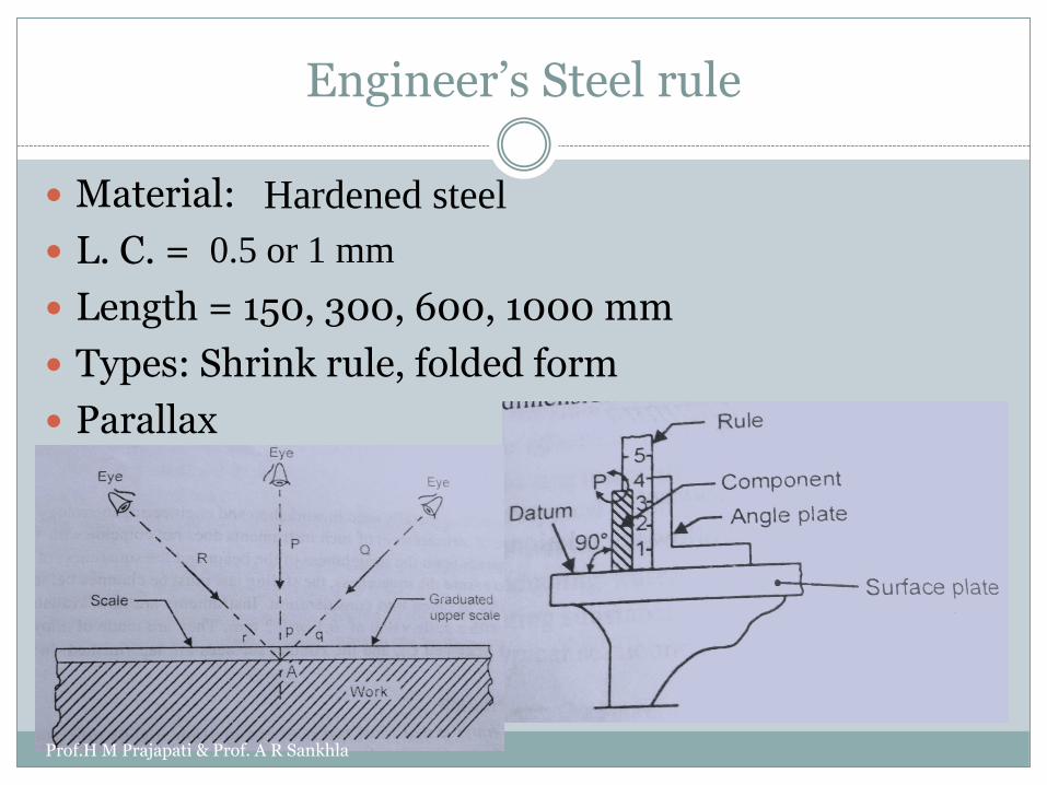
Engineer’s Steel rule
Material:
L. C. =
Length = 150, 300, 600, 1000 mm
Types: Shrink rule, folded form
Parallax
Hardened steel
0.5 or 1 mm
Prof.H M Prajapati & Prof. A R Sankhla
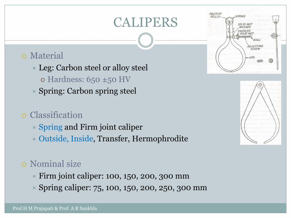
CALIPERS
Material
Leg: Carbon steel or alloy steel
Hardness: 650 ±50 HV
Spring: Carbon spring steel
Classification
Spring and Firm joint caliper
Outside, Inside, Transfer, Hermophrodite
Nominal size
Firm joint caliper: 100, 150, 200, 300 mm
Spring caliper: 75, 100, 150, 200, 250, 300 mm
Prof.H M Prajapati & Prof. A R Sankhla
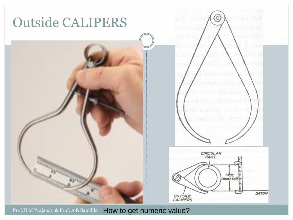
Outside CALIPERS
How to get numeric value?Prof.H M Prajapati & Prof. A R Sankhla

Inside CALIPERS
How to get numeric value?Prof.H M Prajapati & Prof. A R Sankhla
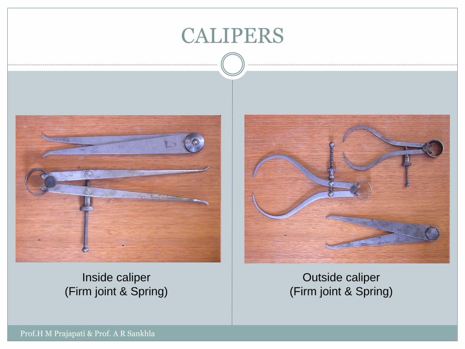
CALIPERS
Inside caliper
(Firm joint & Spring)
Outside caliper
(Firm joint & Spring)
Prof.H M Prajapati & Prof. A R Sankhla

Transfer CALIPERS
Prof.H M Prajapati & Prof. A R Sankhla
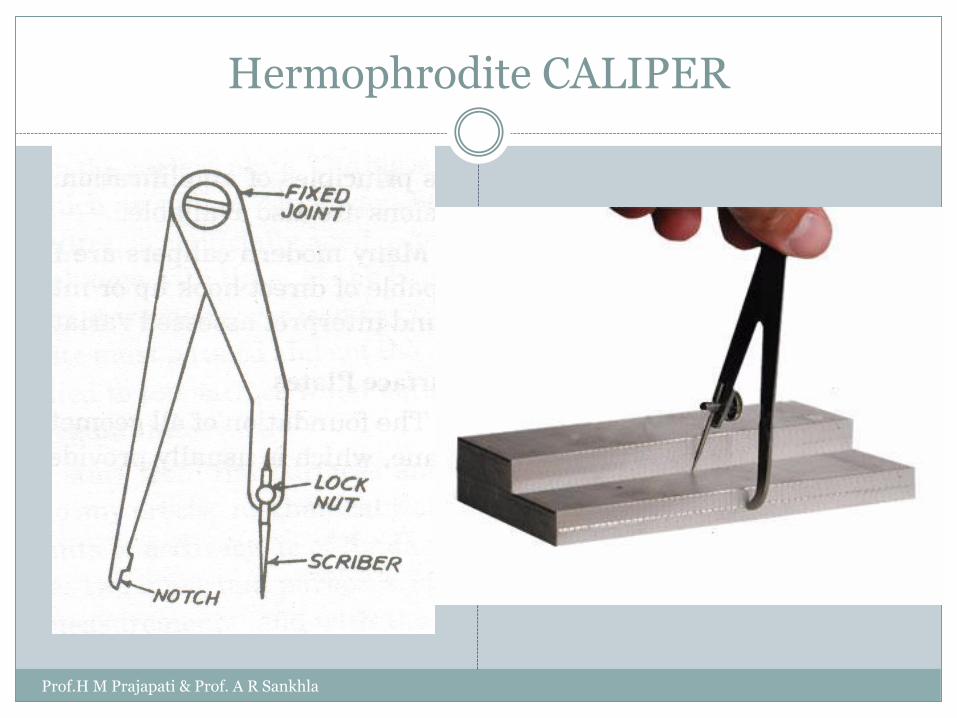
Hermophrodite CALIPER
Prof.H M Prajapati & Prof. A R Sankhla

Divider
Prof.H M Prajapati & Prof. A R Sankhla

Vernier caliper
When two scales or divisions slightly different in sizeare used, then difference between them can beutilized to enhance the accuracy of measurement.
Prof.H M Prajapati & Prof. A R Sankhla

Vernier Caliper
Parts of vernier caliperProf.H M Prajapati & Prof. A R Sankhla

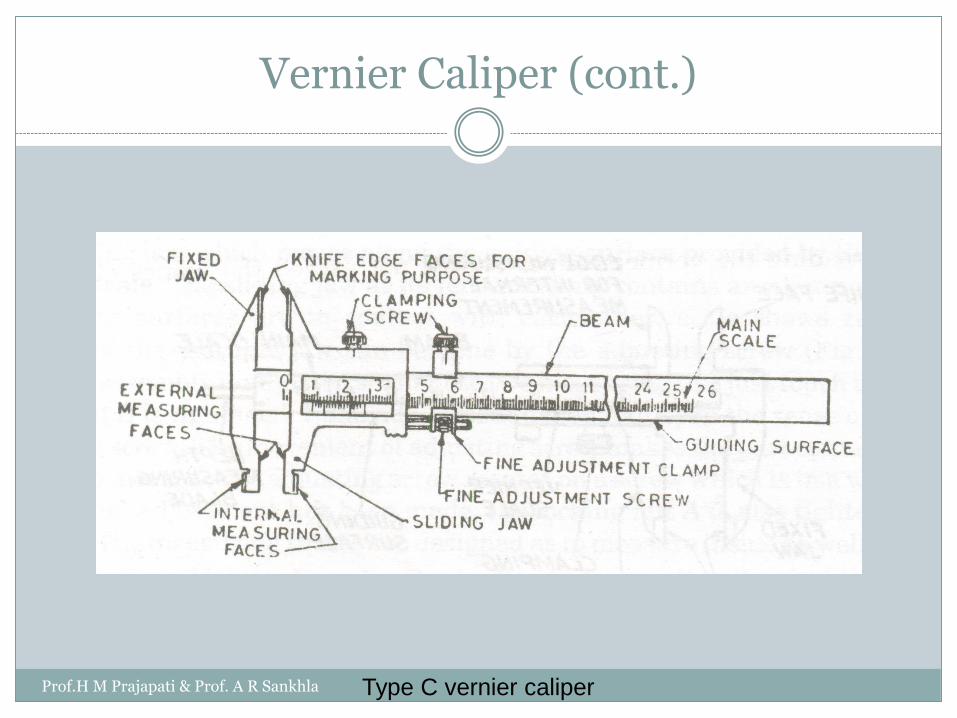
Vernier Caliper (cont.)
Different L.C in vernier caliper
All values are in cm
Prof.H M Prajapati & Prof. A R Sankhla
Vernier Caliper (cont.)
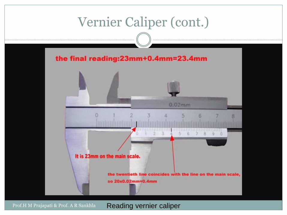
Reading vernier caliperProf.H M Prajapati & Prof. A R Sankhla
Vernier Caliper (cont.)
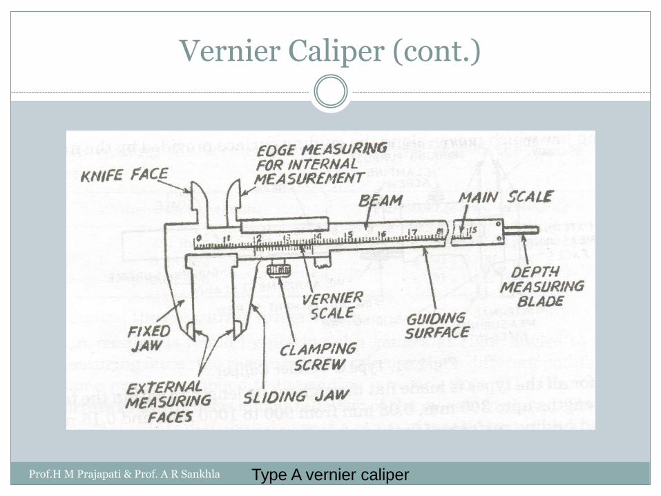
Type A vernier caliperProf.H M Prajapati & Prof. A R Sankhla
Vernier Caliper (cont.)
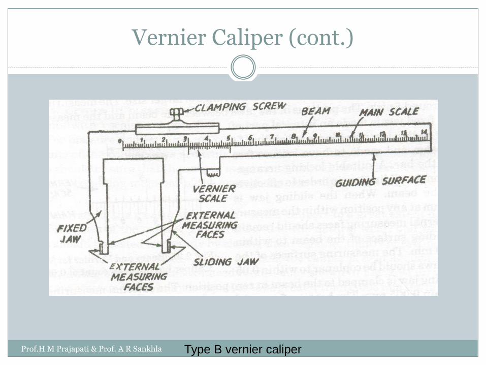
Type B vernier caliperProf.H M Prajapati & Prof. A R Sankhla
Vernier Caliper (cont.)
Type C vernier caliperProf.H M Prajapati & Prof. A R Sankhla

Vernier Caliper (cont.)
Material
Steel
Hardness:
650 HV min.
Range:
0-125, 0-200, 0-250, 0-300, 0-500, 0-750, 0-1000, 750-1500, 750, 2000 mm
Flatness 0.05 mm for nominal
lengths upto 300 mm
Straightness 0.01 mm for measuring
range of 200 mm
Precautions in use
Errors
Prof.H M Prajapati & Prof. A R Sankhla
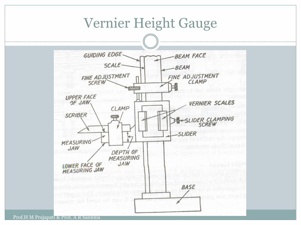
Vernier Height Gauge
Prof.H M Prajapati & Prof. A R Sankhla

Vernier Height Gauge
Base
Flatness: 0.005 mm
Beam
Parallelism of measuring jaw by 0.005 mm/ 10 mm projection of scriber when 1 kg is applied at maximum height of scriber
Straightness of guiding edge
0.02 (250), 0.04(500), 0.06(750), 0.08(1000)
Flatness of beam face
0.04 (250), 0.06(500), 0.10(750), 0.12(1000)
Perpendicularity
0.04 mm /100 mm
Prof.H M Prajapati & Prof. A R Sankhla
Vernier Height Gauge
Measuring jaw and scriber
Parallelism of jaw face with base: 0.008 mm
Graduation
Thickness of graduation: 0.05 to 0.1 mm
Length of graduation: 2 to 3 times the width of interval between adjacent lines
Measure of height
Slider
Good sliding fit
Prof.H M Prajapati & Prof. A R Sankhla

Vernier Depth Gauge
Prof.H M Prajapati & Prof. A R Sankhla
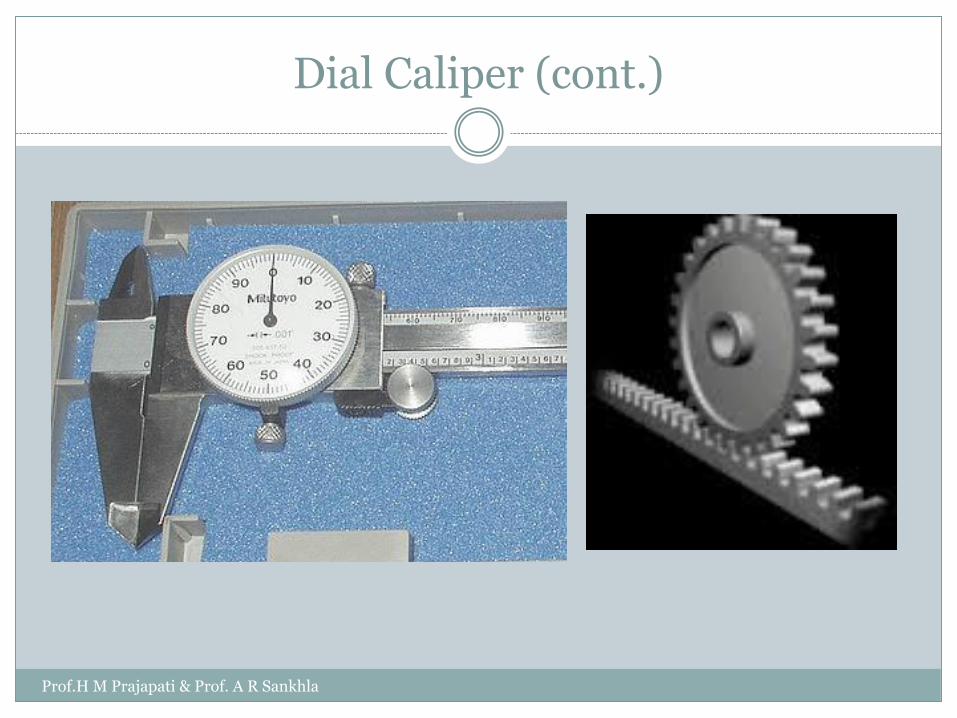
Dial Caliper (cont.)
Prof.H M Prajapati & Prof. A R Sankhla

Digital Caliper
Prof.H M Prajapati & Prof. A R Sankhla
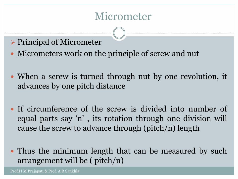
Principal of Micrometer
Micrometers work on the principle of screw and nut
When a screw is turned through nut by one revolution, itadvances by one pitch distance
If circumference of the screw is divided into number ofequal parts say ‘n’ , its rotation through one division willcause the screw to advance through (pitch/n) length
Thus the minimum length that can be measured by sucharrangement will be ( pitch/n)
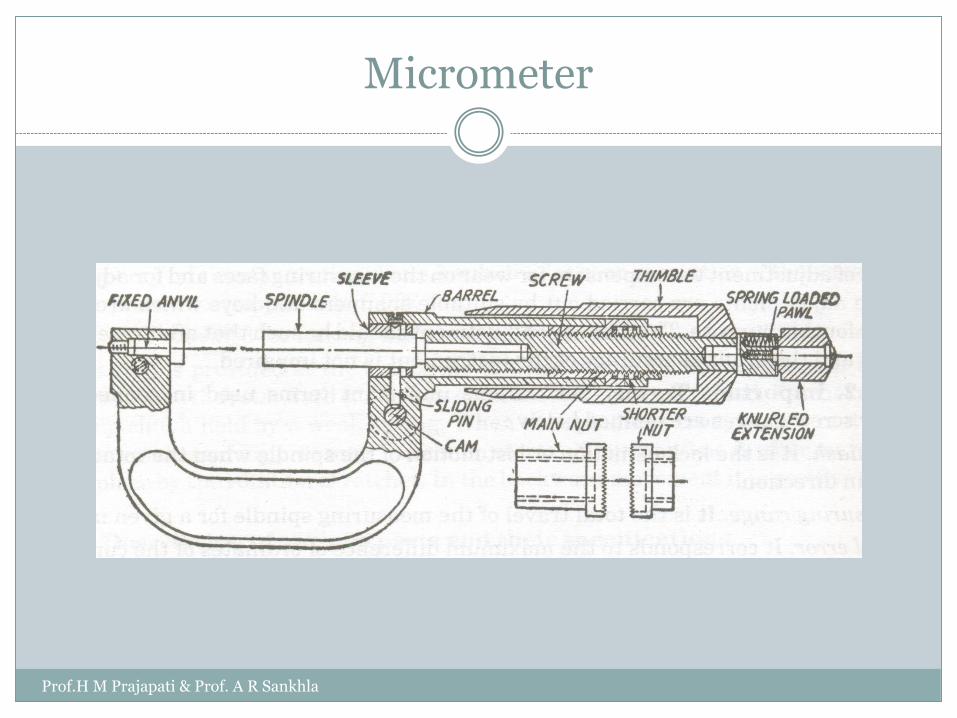
Micrometer
Prof.H M Prajapati & Prof. A R Sankhla
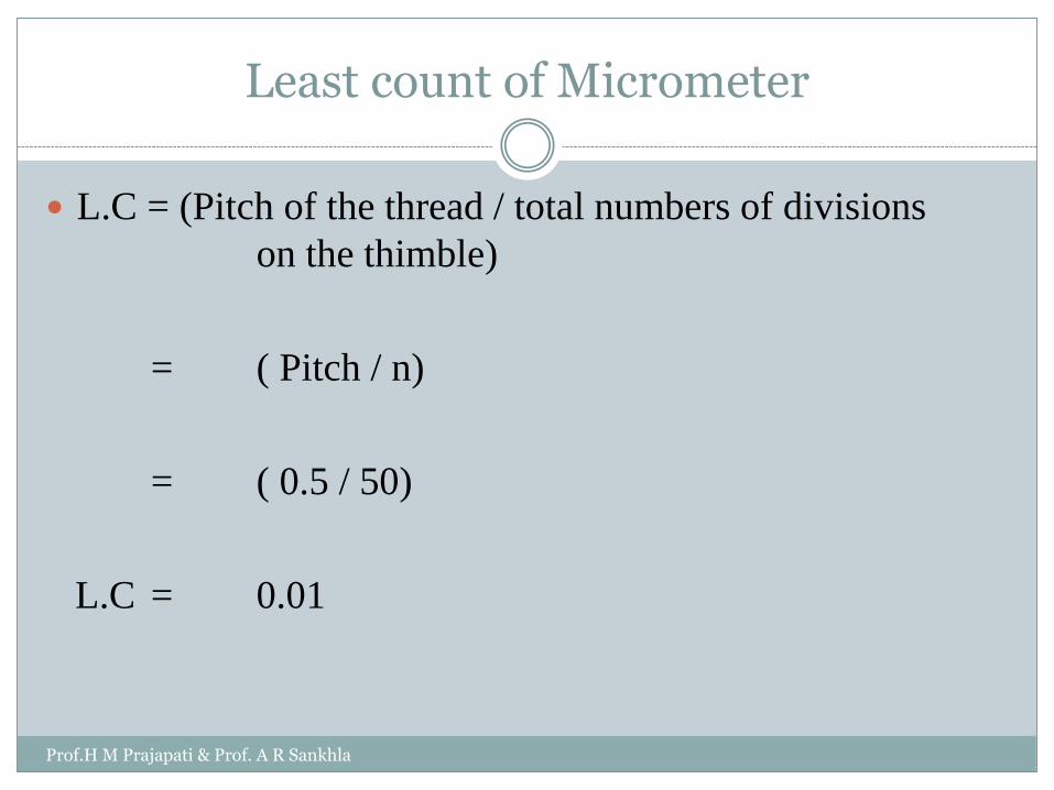
Least count of Micrometer
L.C = (Pitch of the thread / total numbers of divisions
on the thimble)
= ( Pitch / n)
= ( 0.5 / 50)
L.C = 0.01
Prof.H M Prajapati & Prof. A R Sankhla
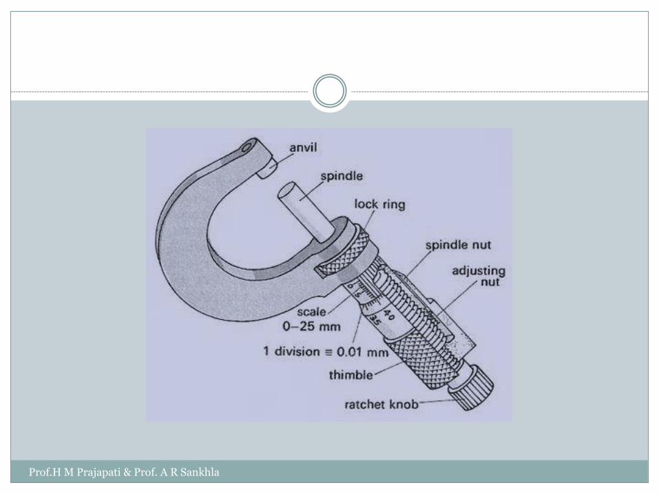
Micrometer
Prof.H M Prajapati & Prof. A R Sankhla
Prof.H M Prajapati & Prof. A R Sankhla
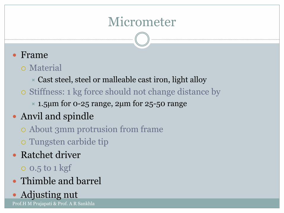
Micrometer
Frame
Material
Cast steel, steel or malleable cast iron, light alloy
Stiffness: 1 kg force should not change distance by
1.5µm for 0-25 range, 2µm for 25-50 range
Anvil and spindle
About 3mm protrusion from frame
Tungsten carbide tip
Ratchet driver
0.5 to 1 kgf
Thimble and barrel
Adjusting nutProf.H M Prajapati & Prof. A R Sankhla
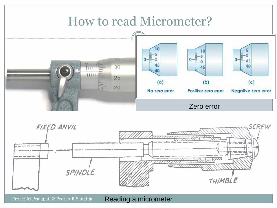
How to read Micrometer?
Reading a micrometer
Zero error
Prof.H M Prajapati & Prof. A R Sankhla

VERNIER MICROMETER
Vernier micrometerProf.H M Prajapati & Prof. A R Sankhla
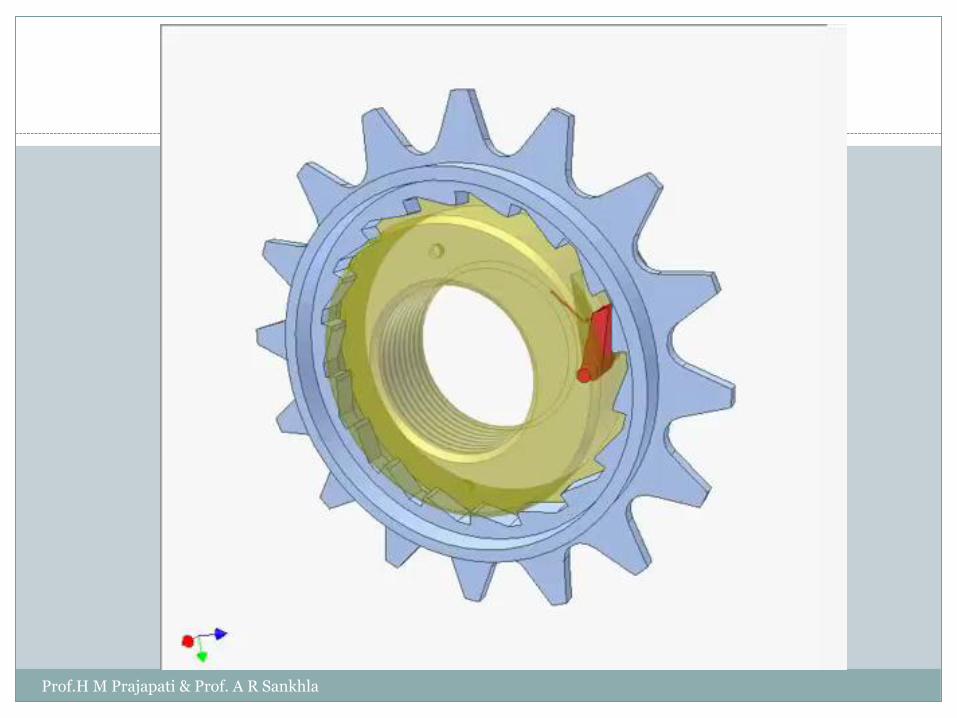
Use of Ratchet Mechanism
To maintain uniform contact pressure less than 1 kgf.
It completely remove the error because of lack of sense of
feel.
Prof.H M Prajapati & Prof. A R Sankhla
Prof.H M Prajapati & Prof. A R Sankhla

Precaution used for micrometer
The micrometer should be wiped clean and free from oil,dirt, dust etc.
Start with zero setting on micrometer. Use spanner tocorrect the error with slight rotation of barrel.
Micrometer dimension is set slightly larger than the size ofPart whose dimensions to be measured and part is slid overthe contact surfaces of micrometer. After this thimble isturned till the measuring tip just touches the part and thefinal movement should be done by ratchet.
The micrometers are available is various sizes and ranges,select appropriate micrometer.
Prof.H M Prajapati & Prof. A R Sankhla
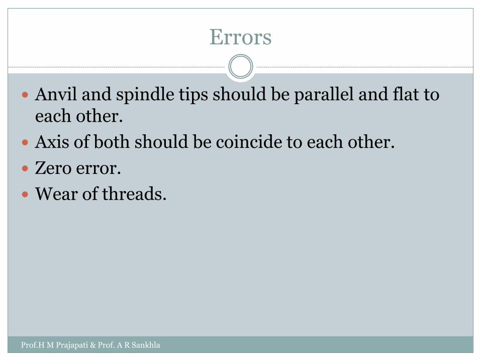
Errors
Anvil and spindle tips should be parallel and flat to each other.
Axis of both should be coincide to each other.
Zero error.
Wear of threads.
Prof.H M Prajapati & Prof. A R Sankhla
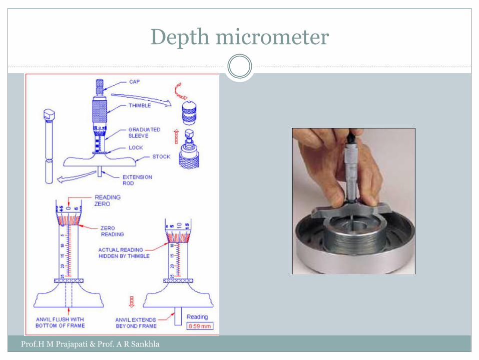
Depth micrometer
Prof.H M Prajapati & Prof. A R Sankhla
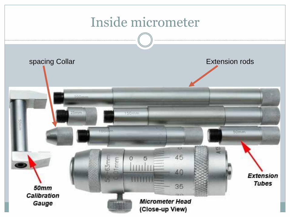
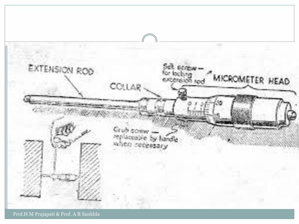
Inside micrometer
spacing Collar Extension rods
Prof.H M Prajapati & Prof. A R Sankhla
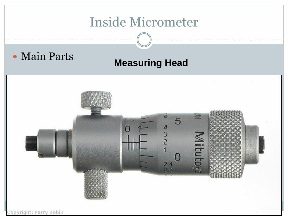
Inside Micrometer
Main PartsMeasuring Head
Prof.H M Prajapati & Prof. A R Sankhla
Prof.H M Prajapati & Prof. A R Sankhla
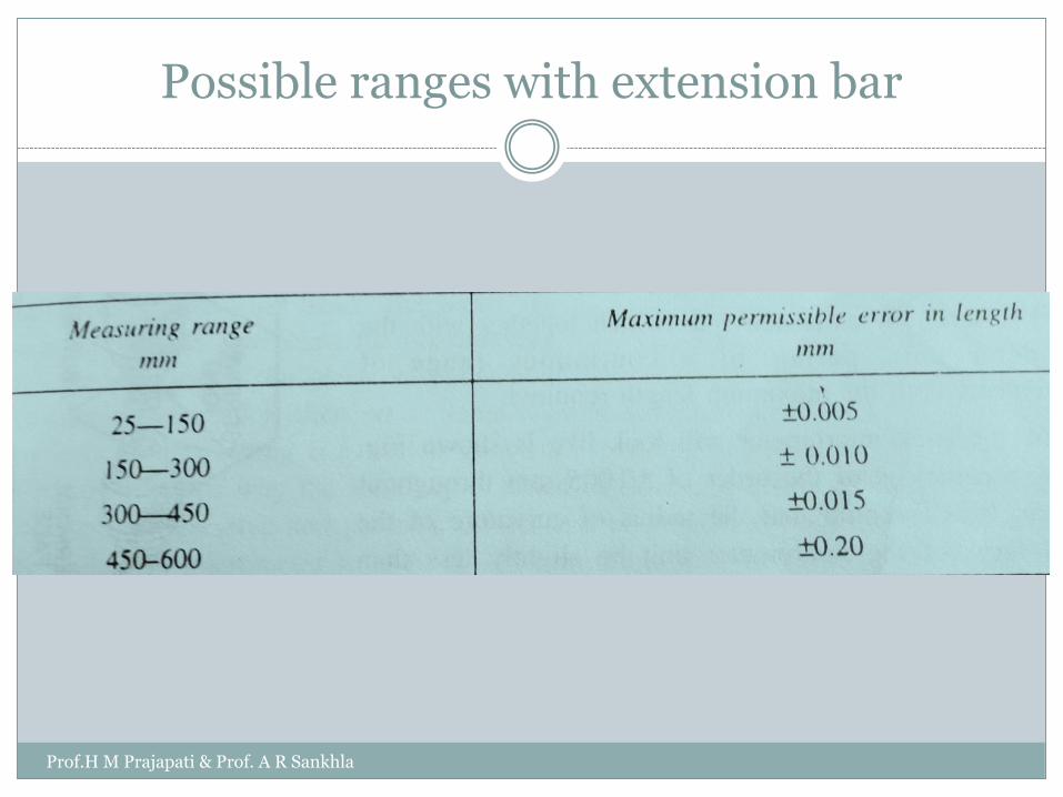
Possible ranges with extension bar
Prof.H M Prajapati & Prof. A R Sankhla

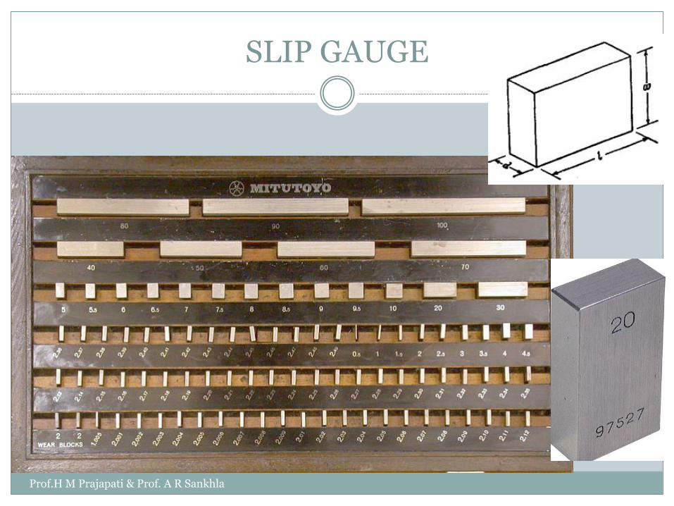
SLIP GAUGE
Johannsen gauges
Cross-section:30 mm×09 mm
Classification
As per accuracy
Master slip gauge AA: ±2µ/m
Reference slip gauge A: ±4µ/m
Working slip gauge B: ±8µ/m
As per grade
Grade 2: Workshop grade
Grade 1: Tool room work (setting up sine bar & Dual Gauge, checking gap gauges)
Grade 0: Inspection grade (Inspection Dept.)
Grade 00: Calibration of Grade 2
Prof.H M Prajapati & Prof. A R Sankhla
SLIP GAUGE
Prof.H M Prajapati & Prof. A R Sankhla
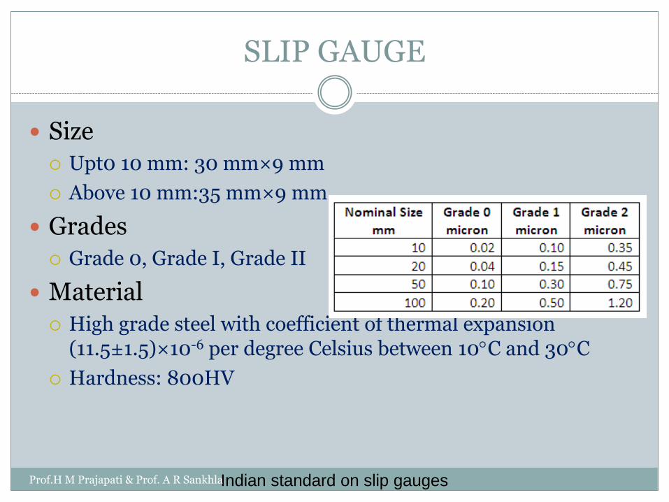
SLIP GAUGE
Size
Upt0 10 mm: 30 mm×9 mm
Above 10 mm:35 mm×9 mm
Grades
Grade 0, Grade I, Grade II
Material
High grade steel with coefficient of thermal expansion (11.5±1.5)×10-6 per degree Celsius between 10C and 30C
Hardness: 800HV
Indian standard on slip gaugesProf.H M Prajapati & Prof. A R Sankhla

SLIP GAUGE
Wringing of slip gaugesProf.H M Prajapati & Prof. A R Sankhla
0.00635 microns

Slip Gauge set as per Indian Standard
M45/1 & M86/1
Prof.H M Prajapati & Prof. A R Sankhla

Selection of slip gauges for required dimension
Make a stake of 55.289
Always start with the last decimal place and deduct this
from the required dimension. For example, let’s the
dimension is to be built up is 55.289.
Here for last decimal place of 0.009, select 1.009 mm
slip gauge. Now dimension left = 55.289-1.009 = 54.28
mm
Select next smallest figure in the same way, find the
remainder and continue this until the required
dimension is completed
Prof.H M Prajapati & Prof. A R Sankhla

In our example second decimal place is 1.08,select
1.08 mm slip gauge
Now remainder = 54.28 -1.08 = 53.2mm
Now select 1.2 mm and 52 mm is the remaining
dimension.
Now select 2 mm slip gauge so remainder 50 mm. 50
mm slip gauge is available directly.
Thus we have 50+2+1.2+1.08+1.009 = 29.758 mm
Prof.H M Prajapati & Prof. A R Sankhla
Care & Use of slip Gauges.
Surfaces should be covered with petroleum jelly or othercorrosive resistance coatings.
When the gauges are not in use they should be kept in their casewith size.
The gauges should be used in air conditioner rooms free fromdust and dirt.
The fingering/Handling of lapped faces should be avoided as faras possible that may corrode surfaces due to natural acid in theskin.
The working surfaces should never be placed on surface plate.
Use standard wringing process to make stake of gauges.
The gauges should never be left wrung together for anunnecessary length of time. This may lead to micro cold weldingwhich may cause pitting of surface when they are separated.
Prof.H M Prajapati & Prof. A R Sankhla
SURFACE PLATE
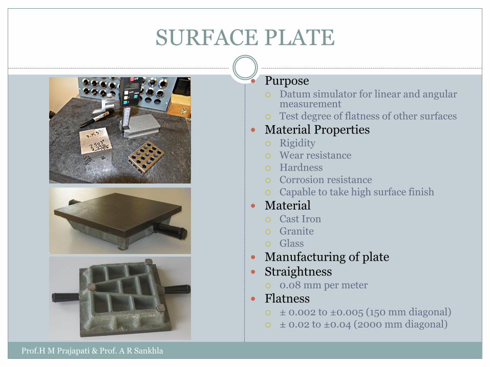
Purpose Datum simulator for linear and angular
measurement Test degree of flatness of other surfaces
Material Properties Rigidity Wear resistance Hardness Corrosion resistance Capable to take high surface finish
Material Cast Iron Granite Glass
Manufacturing of plate Straightness
0.08 mm per meter
Flatness ± 0.002 to ±0.005 (150 mm diagonal) ± 0.02 to ±0.04 (2000 mm diagonal)
Prof.H M Prajapati & Prof. A R Sankhla
Care & Use of Surface Plate
Before and after use of surface plate, it should be wiped clean
from dust and other particles.
Surface plate should be placed in stirred atmosphere under
constant temperature control. Keep it away from direct sunlight.
Load should be distributed over working surface.
Full area of plate should be utilized. Do not concentrate on
particular area.
The excess metal due to burrs on the surface of CI surface plate
should be removed.
Flatness should be checked occasionally.
Protect it against damage by direct falling of heavy objects.
When not in use, it should always be kept oil lubricated in cover.
Prof.H M Prajapati & Prof. A R Sankhla
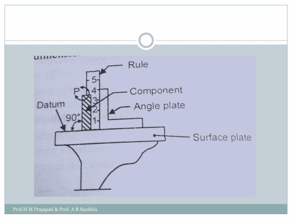
ANGLE PLATE
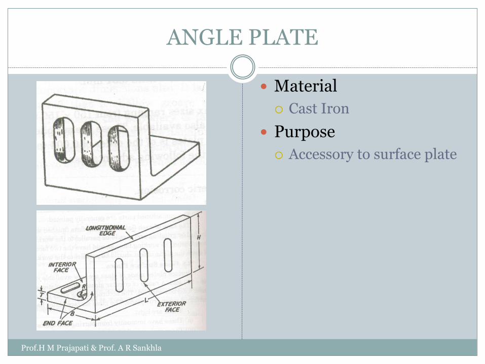
Material
Cast Iron
Purpose
Accessory to surface plate
Prof.H M Prajapati & Prof. A R Sankhla
Prof.H M Prajapati & Prof. A R Sankhla
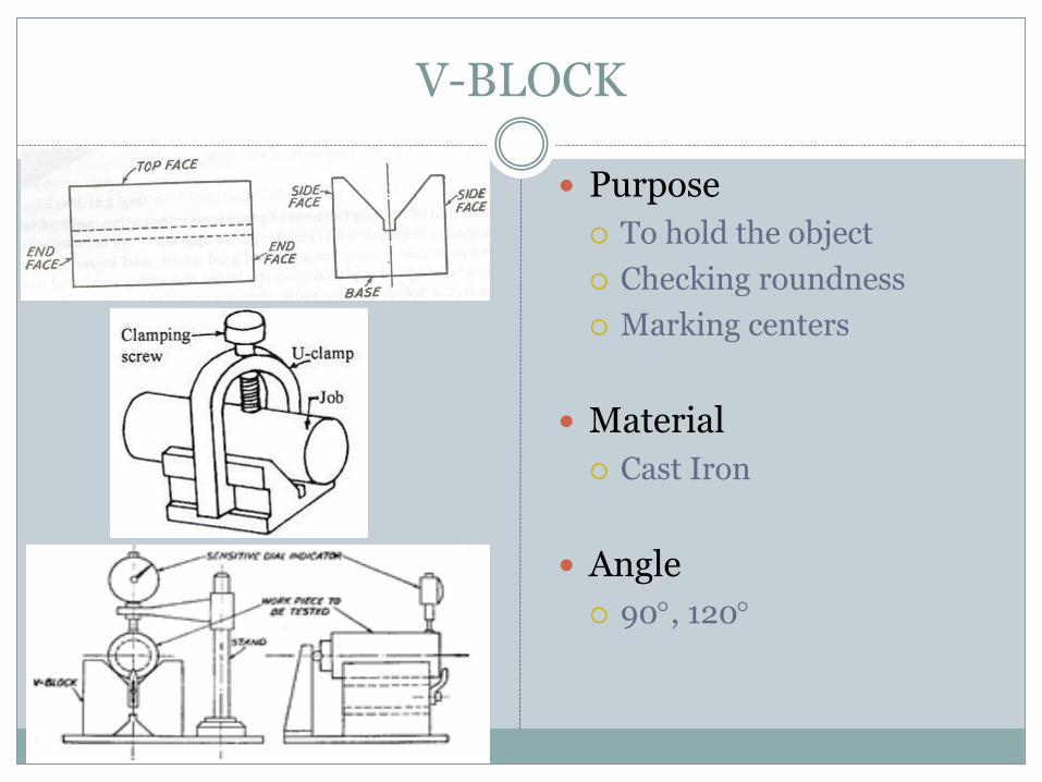
V-BLOCK
Purpose
To hold the object
Checking roundness
Marking centers
Material
Cast Iron
Angle
90, 120
Prof.H M Prajapati & Prof. A R Sankhla
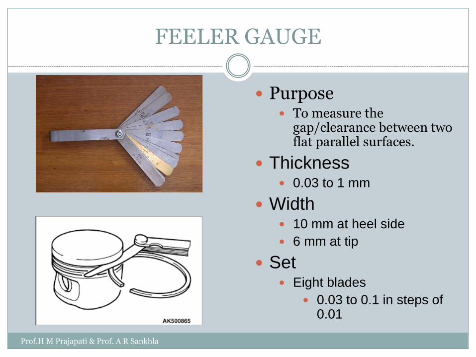
FEELER GAUGE
Purpose To measure the
gap/clearance between two flat parallel surfaces.
Thickness 0.03 to 1 mm
Width 10 mm at heel side
6 mm at tip
Set Eight blades
0.03 to 0.1 in steps of 0.01
Prof.H M Prajapati & Prof. A R Sankhla
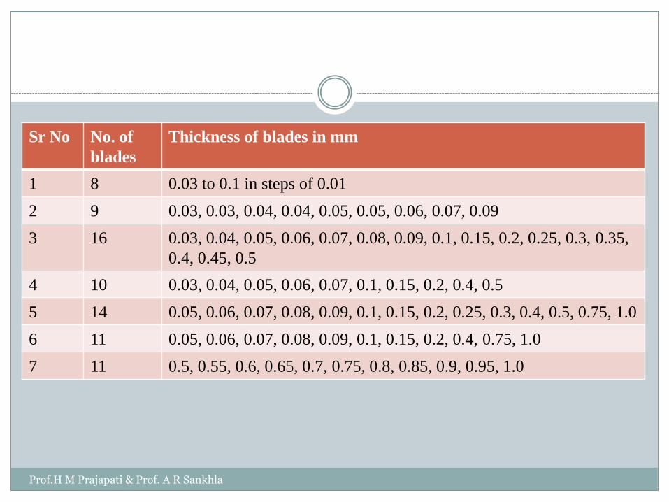
Sr No No. of
blades
Thickness of blades in mm
1 8 0.03 to 0.1 in steps of 0.01
2 9 0.03, 0.03, 0.04, 0.04, 0.05, 0.05, 0.06, 0.07, 0.09
3 16 0.03, 0.04, 0.05, 0.06, 0.07, 0.08, 0.09, 0.1, 0.15, 0.2, 0.25, 0.3, 0.35,
0.4, 0.45, 0.5
4 10 0.03, 0.04, 0.05, 0.06, 0.07, 0.1, 0.15, 0.2, 0.4, 0.5
5 14 0.05, 0.06, 0.07, 0.08, 0.09, 0.1, 0.15, 0.2, 0.25, 0.3, 0.4, 0.5, 0.75, 1.0
6 11 0.05, 0.06, 0.07, 0.08, 0.09, 0.1, 0.15, 0.2, 0.4, 0.75, 1.0
7 11 0.5, 0.55, 0.6, 0.65, 0.7, 0.75, 0.8, 0.85, 0.9, 0.95, 1.0
Prof.H M Prajapati & Prof. A R Sankhla
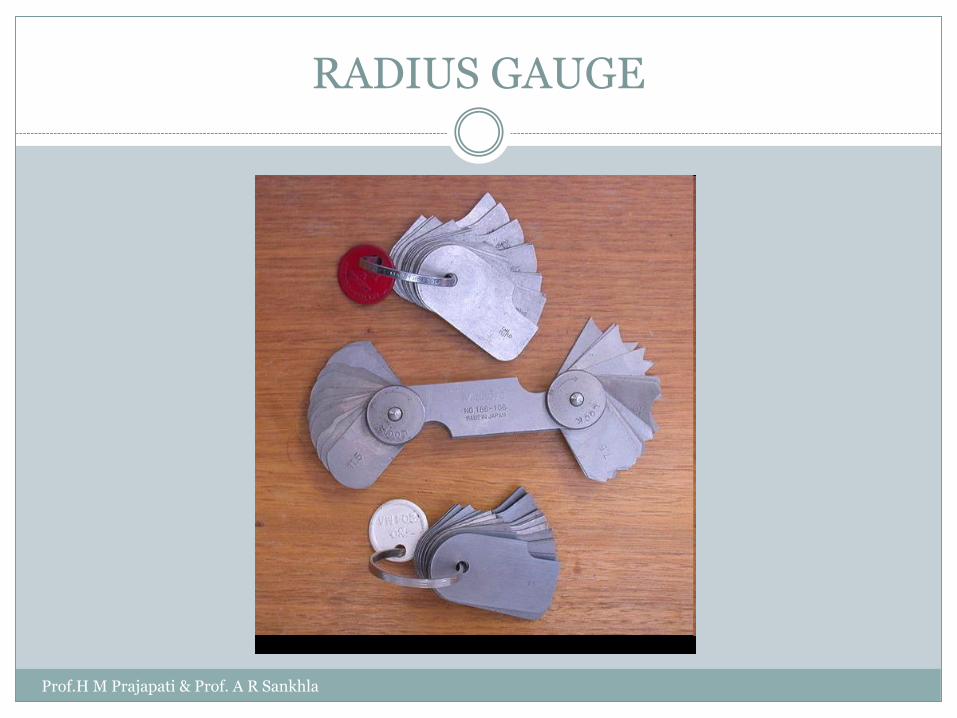
RADIUS GAUGE
Prof.H M Prajapati & Prof. A R Sankhla

THREAD PITCH GAUGE
Prof.H M Prajapati & Prof. A R Sankhla
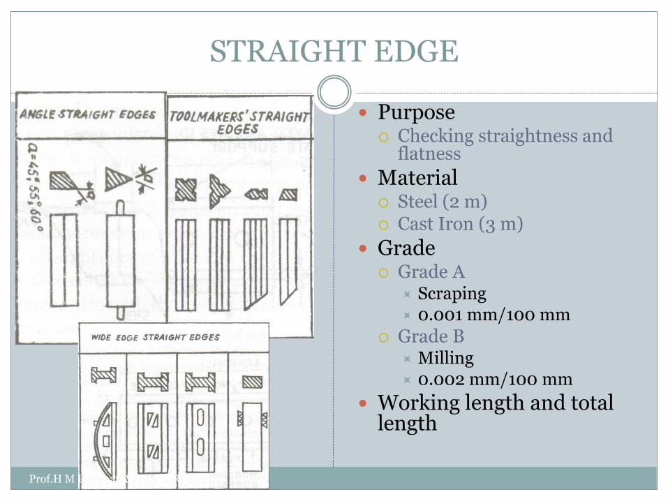
STRAIGHT EDGE
Purpose Checking straightness and
flatness
Material Steel (2 m) Cast Iron (3 m)
Grade Grade A
Scraping 0.001 mm/100 mm
Grade B Milling 0.002 mm/100 mm
Working length and total length
Prof.H M Prajapati & Prof. A R Sankhla

STRAIGHT EDGE (CONTD.)
Prof.H M Prajapati & Prof. A R Sankhla
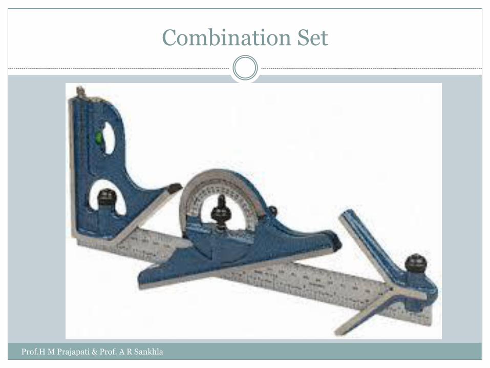
Combination Set
Prof.H M Prajapati & Prof. A R Sankhla
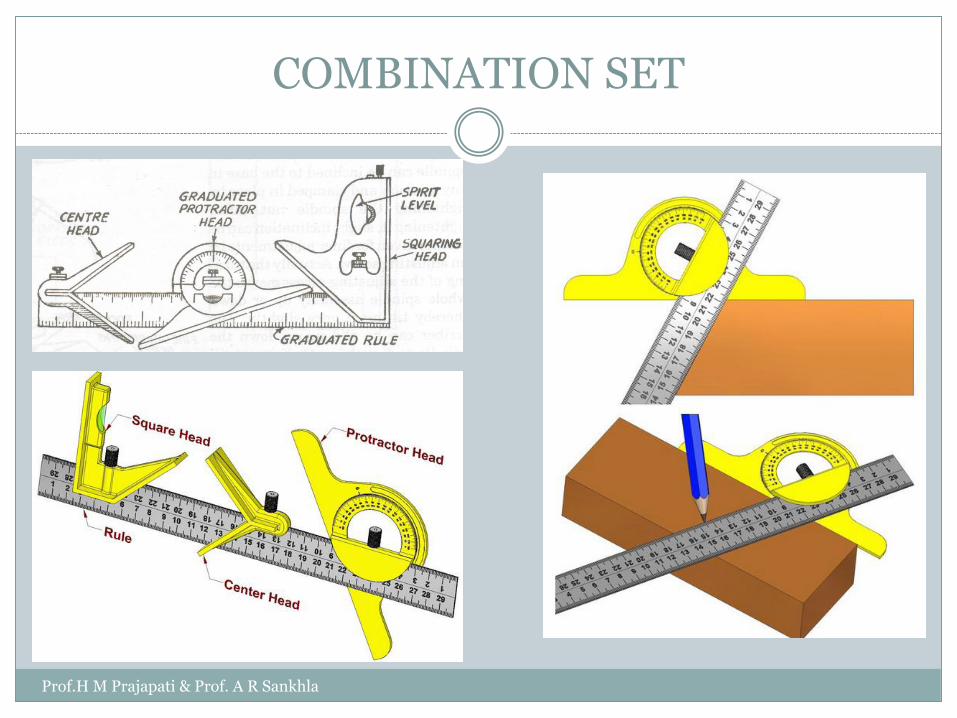
COMBINATION SET
Prof.H M Prajapati & Prof. A R Sankhla
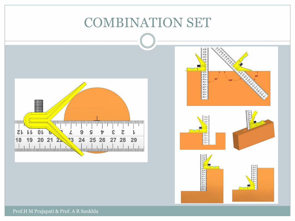
COMBINATION SET
Prof.H M Prajapati & Prof. A R Sankhla
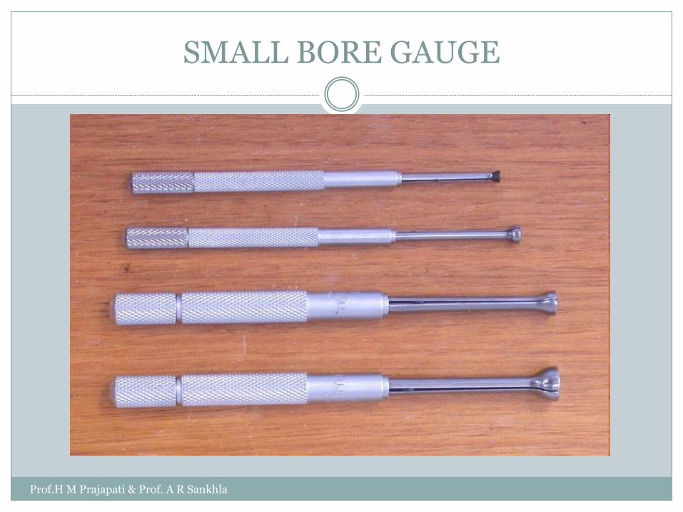
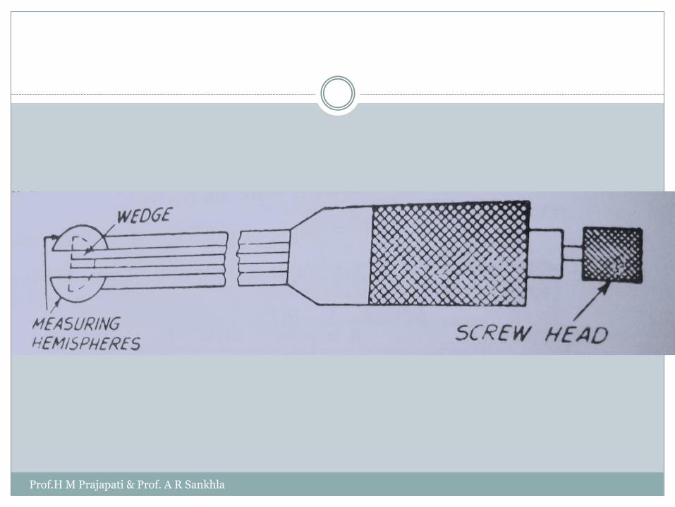
SMALL BORE GAUGE
Prof.H M Prajapati & Prof. A R Sankhla
Prof.H M Prajapati & Prof. A R Sankhla
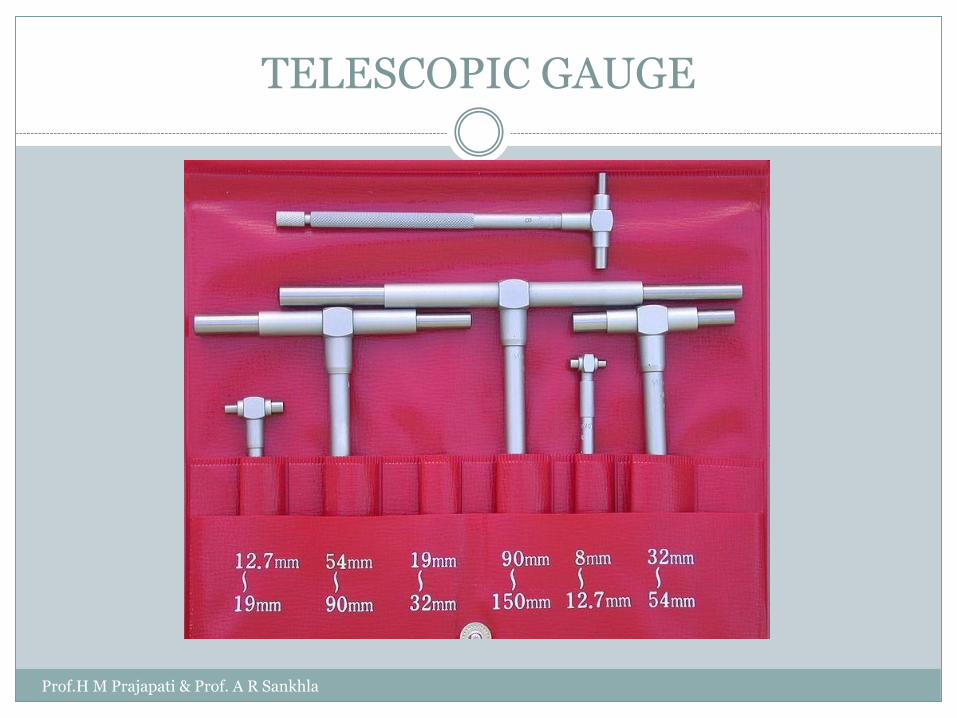
TELESCOPIC GAUGE
Prof.H M Prajapati & Prof. A R Sankhla

PIN GAUGE METHOD TO MEASURE BORE DIAMETER
Prof.H M Prajapati & Prof. A R Sankhla
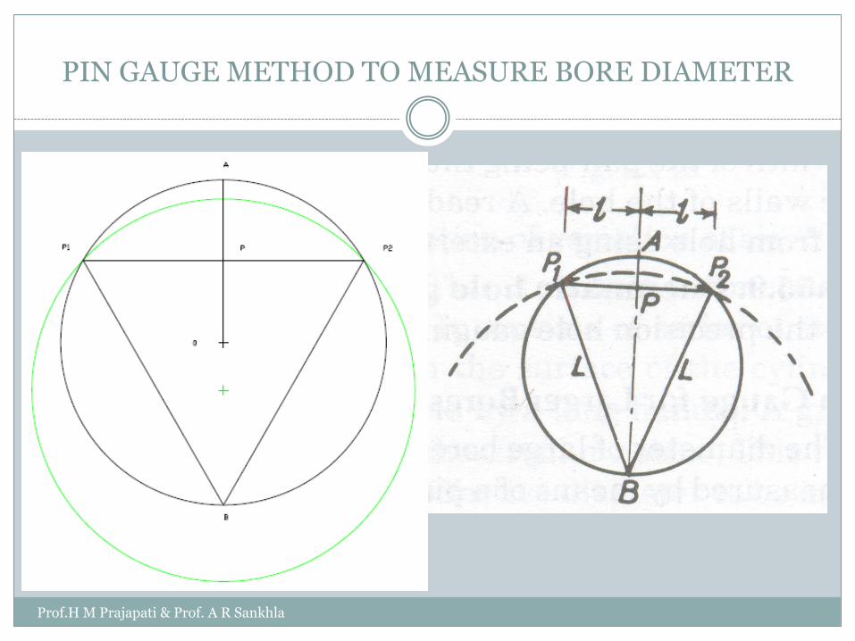
PIN GAUGE METHOD TO MEASURE BORE DIAMETER
Prof.H M Prajapati & Prof. A R Sankhla
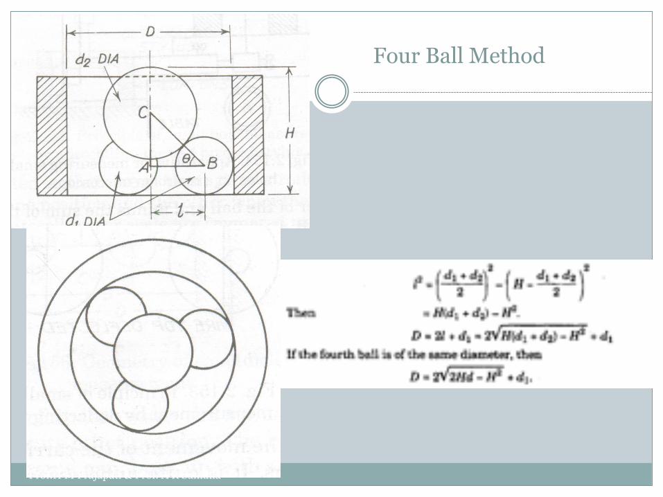
Four Ball Method
Prof.H M Prajapati & Prof. A R Sankhla
Prof.H M Prajapati & Prof. A R Sankhla

Parallax error numerical
Chapter 1 Introduction
Worked Examples
Q 1.8
Book: Engineering Metrology by R K Jain
Prof.H M Prajapati & Prof. A R Sankhla
Transfer from line standard to end standard
Chapter 3:
Topic 3.5.2
Book: Engineering Metrology by R K Jain
Solved Examples:
Q. 3.3 and 3.4
Prof.H M Prajapati & Prof. A R Sankhla