Embed Size (px)
Citation preview

FLUE GASDESULPHURISATION
(FGD) TECHNOLOGIES
TECHNOLOGYSTATUS REPORT
Department of Trade and IndustryM A R C H 2 0 0 0
T E C H N O L O G Y
S TAT U S R E P O R T
012
CLEA
NER C
OAL T
ECHN
OLOG
Y PRO
GRAM
ME
1751 TSR 012 31/5/00 3:59 pm Page 14

Further information on the Cleaner Coal Technology Programme, and copies of publications, can be obtained from:
Roshan Kamall, Location 1124, Department of Trade and Industry,1 Victoria Street, London SW1H 0ET
Tel: +44 (0) 207 215 6261Fax: +44 (0) 207 215 2674
E-mail: [email protected]: www.dti.gov.uk/ent/coal
1751 TSR 012 31/5/00 3:59 pm Page 15

S U M M A R YFlue gas desulphurisation (FGD) technologies are widely used to controlthe emissions of sulphur dioxide (SO2) and sulphur trioxide (SO3) fromlarge stationary sources such as coal- and oil-fired power stations andrefineries. They are to be distinguished from the flue gas treatment (FGT)processes used for removing pollutants from waste incinerators.
A variety of FGD processes are available; most use an alkali sorbent torecover the acidic sulphur compounds from the flue gas. The most widelyused processes are the limestone gypsum process, which produces asaleable gypsum by-product, variants of the limestone process thatproduce a disposable sludge, and the spray dry process, which produces amixed solid waste.
Capital costs of FGD processes have been steadily falling and current costsare in the range US$100-125 kW-1 (£65-80 kW-1), with further falls incost predicted for 2000 and beyond. The total market for FGD plant islikely to exceed £1Bn pa over the next decade, with North America andChina being the largest markets.
Current research and development (R&D) needs are to further reducecosts, increase desulphurisation efficiencies and improve the reliability ofplant components.
B E N E F I T S O F T H ET E C H N O L O G YFGD is widely applicable as a means of controlling SO2 emissions fromlarge, stationary sources such as power stations, refineries andmetallurgical plant (eg Figure 1). The widespread adoption of FGD,together with measures to reduce SO2 emissions from other sources (egreplacement of coal by electricity or gas for domestic heating; low sulphurmotor fuels) will significantly reduce anthropogenic sulphur emissionsworldwide and thus help to improve air quality to the benefit of bothhuman health and the environment.
D E P A R T M E N T O F T R A D E A N DI N D U S T R Y S U P P O R TSince 1990, the Department of Trade and Industry (DTI) has supported 8projects associated with FGD, contributing £320k to total project costs of£1887k.
I N T R O D U C T I O NSulphur is one of the most common elements in the earth’s crust, andoccurs widely as an impurity in coal, crude oil and many ores. It istherefore produced on a large scale during such industrial processes as thecombustion of coal, oil and oil-derived fuels, oil refining and theproduction of metals from their ores. Currently, global SO2 emissionsarising from human activity amount to ~140 million tonnes (Mt) per year,of which ~2Mt (1.4%) is produced by the UK. The UK’s SO2 emissionshave, however, fallen significantly over the past 30 years (Figure 2).
SO2 is one of the principal gaseous pollutants emitted by human activity.It can be a hazard to human health and damages both the natural andbuilt environments. High levels of SO2 can cause respiratory illness and itspresence in the environment causes acid rain that damages bothvegetation and buildings. Control and reduction of SO2 emissions hastherefore been recognised as important for safeguarding human healthand protecting the environment since the mid-19th century; manycountries now set limits on the amount and concentration of sulphurcompounds emitted from the stacks of industrial plant.
Emissions of SO2 can be controlled in several ways. It may be possible toswitch to a fuel or ore that has a lower sulphur content, or improve theefficiency of the industrial process so that less fuel is required. Thesulphur in the fuel or ore can in principle be removed before use;however, in practice, it is uneconomic to remove more than a smallpercentage of the sulphur. The sulphur can also be removed during use.However, in many applications, the most efficient means of controlling
Figure 1. Ratcliffe-on-Soar FGD (Courtesy of PowerGen UK plc)
FLUE GAS DESULPHURISATION (FGD) TECHNOLOGIES
1751 TSR 012 31/5/00 3:59 pm Page 1

SO2 emissions is to remove the SO2 from the flue gases before they arereleased to the atmosphere. Several differing FGD technologies have beendeveloped to this end.
F U N D A M E N T A L S O F F G DChemical Pr inc iples
Almost all commercial FGD processes are based on the fact that SO2 isacidic in nature, and remove the SO2 from flue gases by reaction with asuitable alkaline substance. The most commonly used alkaline materialsare limestone (calcium carbonate), quicklime (calcium oxide, CaO) andhydrated lime (calcium hydroxide). Limestone is an abundant andtherefore relatively cheap material and both quicklime and hydrated limeare produced from limestone by heating. Other alkalis sometimes usedinclude sodium carbonate, magnesium carbonate and ammonia.
The alkali used reacts with SO2 in the flue gas to produce a mixture ofsulphite and sulphate salts (of calcium, sodium, magnesium or ammonium,depending on the alkali used). The proportions of sulphite and sulphateare determined by the process conditions; in some processes, all thesulphite is converted to sulphate.
The reaction between the SO2 and the alkali can take place either in bulksolution (‘wet’ FGD processes) or at the wetted surface of the solid alkali(‘dry’ and ‘semi-dry’ FGD processes).
In wet FGD systems, the alkali (usually as a solution or, more commonly, aslurry) and flue gas are contacted in a spray tower. The SO2 in the flue gasdissolves in the water to form a dilute solution of acid that then reactswith and is neutralised by the dissolved alkali. The sulphite and sulphatesalts produced precipitate out of solution, depending on the relativesolubility of the different salts present. Calcium sulphate, for example, isrelatively insoluble and readily precipitates out. Sodium and ammoniumsulphates are very much more soluble.
In dry and semi-dry systems, the solid alkali ‘sorbent’ is brought intocontact with the flue gas, either by injecting or spraying the alkali into thegas stream or by passing the flue gas through a bed of alkali. In eithercase, the SO2 reacts directly with the solid to form the correspondingsulphite and sulphate. For this to be effective, the solid has to be quiteporous and/or finely divided. In semi-dry systems, water is added to theflue gas to form a liquid film on the particles in which the SO2 dissolves,promoting the reaction with the solid.
Select ion of FGD Processes
There are a wide range of FGD processes on offer, differing significantly interms of sorbent used, by-products produced, removal efficiency andcapital cost. Selection of the most appropriate FGD process for aparticular application will normally be made on economic grounds, ie theprocess with the lowest overall through-life cost. However, there are manydifferent factors that affect the overall cost. These include:
• Technical considerations.
• Economic issues- operating costs- capital costs.
• Commercial considerations.
Technical considerations include the degree of desulphurisation that theprocess can offer, the flexibility of the process, the amount of space thatthe FGD plant requires and the technical risks. Economic issues include thecapital and operating costs, including consideration of the cost of theplant itself (which may be appreciably more if the plant is to be retrofittedto an existing boiler), the costs of the sorbent used, any revenues orexpenses arising from disposal of the by-products and maintenance costs.Commercial considerations include the degree of commercial risk, thematurity of the technology, the number and size of units already inoperation (and how they have performed) and suppliers’ guarantees.
Some of the major FGD processes are described below. These are:
• Wet Processes:- limestone gypsum- sea-water washing- ammonia scrubbing- Wellman-Lord.
• Semi-dry Processes:- circulating fluidised bed- spray dry- duct spray dry.
• Dry Processes- furnace sorbent injection- sodium bicarbonate injection.
F G D P R O C E S S E SLimestone Gypsum
In the limestone gypsum wet scrubbing process, the flue gas is treatedwith limestone slurry, in order to remove the SO2 and neutralise it. Thefinal product is calcium sulphate dihydrate (gypsum).
This is the most common FGD process now being installed worldwide, andhas evolved over almost 30 years. Nowadays, a plant would normally bedesigned to achieve a high-quality gypsum product, which is suitable forwallboard manufacture. Earlier limestone-based FGD processes producedsulphite sludge or gypsum for dumping, but these types of design are notoften adopted now. Both of the large UK power plant with FGD, Ratcliffe(Figure 3) and Drax, use the limestone gypsum process.
There are a number of process variants and equipment arrangementswhich can be adopted; eg the absorber type and reheat methods can varywith the supplier and with the client’s requirements. The design chosenhere for illustrative purposes (Figure 4) is one of the most commonlimestone gypsum (wallboard) plant types, and consists of an open spraytower with a rotary regenerative reheater. The limestone gypsum plant islocated downstream of the electrostatic precipitator (ESP) or bag filter, sothat most of the fly ash from combustion is removed before the gasreaches the FGD plant. For coal-fired plant, fly ash removal would be~99.5%.
1970 1980 1985
Large combustion plant Total
1988 1989 1990 1991
Year
SO2
Emitt
ed (
kt)
1992 1993 1994 1995 1996
Figure 2. Trends in UK SO2 emissions
Figure 3. Ratcliffe-on-Soar FGD (under construction) (Courtesy of PowerGen UK plc)
1751 TSR 012 31/5/00 3:59 pm Page 2

Flue gas from the ESP passes through an induced draught (ID) and/orbooster fan and enters the gas/gas reheater. Here the gas is cooled asheat is extracted. The warm gas from the reheater enters the absorberand mixes with the process liquor. Some of the water is evaporated, andthe gas is further cooled. The gas is scrubbed with the recirculatinglimestone slurry to remove the required amount of SO2. FGD plantmanufacturers generally claim that over 95% of the SO2 can be removedwithin the absorber. This process also removes almost 100% of anyhydrogen chloride (HCl) in the flue gas. At the top of the absorber, thegas passes through de-misters to remove suspended water droplets.
After leaving the absorber, the gas is passed through the reheater again,to raise its temperature before being exhausted to the stack. Absorberoutlet temperatures are typically 50-70ºC, depending mainly on the type offuel burnt. The minimum gas temperature at the stack is often specified innational emission standards. In the UK this is 80ºC, but in mainlandEurope it is slightly lower. Most plant have a by-pass duct, fitted with a(normally closed) damper. This would be opened in an emergency orduring start-up, to allow flue gas to be diverted past the FGD plant,directly to the stack.
Limestone/gypsum slurry is pumped from the absorber sump to the sprayheaders at the top of the scrubber. As the slurry falls down the tower itcontacts the rising flue gas. The SO2 is dissolved in the water, neutralisedand thus removed from the flue gas. Calcium carbonate from thelimestone reacts with the SO2 and oxygen (O2 from air), ultimately toproduce gypsum, which precipitates from solution in the sump. HCl is alsodissolved in the water and neutralised to produce calcium chloride solution.
Fresh limestone slurry is pumped into the sump to maintain the requiredpH. At many plant, crushed limestone is milled on site before beingslurried and pumped into the absorber sump. Although a certain amountof liquor oxidation occurs naturally due to excess air in the flue gas, thesump liquor is sparged with air, oxidising any remaining bisulphite tosulphate. Gypsum slurry (contaminated with ~3% limestone) is extractedfrom the absorber sump, thickened, de-watered and washed forsubsequent storage before dispatch from site.
As described above, HCl is removed from the flue gas in the scrubber, toproduce calcium chloride in solution. In addition to this, trace quantitiesof fly ash are also removed from the flue gas. These and impurities in thelimestone will accumulate in the process liquor as dissolved metal salts andsuspended minerals such as quartz. The concentrations of thesecontaminants must be controlled to ensure the gypsum purity ismaintained at the required level and high concentrations of chloride donot inhibit the desulphurisation process chemistry. The system is purgedwith water to control the concentration of these contaminants. Freshwater is added to the absorber via the de-mister wash. The purge streamis taken off as the overflow from the hydrocyclone system used for gypsumthickening. The purge stream, which contains dissolved solids and veryfine suspended particles, is sent to the waste-water treatment plant. Herelime is added to raise the pH and precipitate heavy metals from solution.The treated water is then normally discharged from site.
Despite falling prices, the limestone gypsum process should still beregarded as relatively high in capital cost, significantly higher than mostother processes except ammonia scrubbing and the regenerative types. Itis also more complex than some other process types. However, for manyapplications it will provide a lower operating cost than other, lime-basedprocesses. This is because limestone is normally much cheaper than lime,and normally the by-product gypsum can be sold rather than incurring adisposal cost. This becomes particularly important for plant with a highsorbent consumption.
The limestone gypsum process will usually offer the lowest through-lifecost option for large inland plant with medium- to high-sulphur fuel, ahigh load factor and a long residual life.
The limestone gypsum process is the most well-developed and widelyadopted FGD process worldwide, and is the one normally adopted for alarge power station. The total worldwide installed capacity isapproximately 149,000MWe for coal-fired plant alone. The technology isvery well understood and is offered by many contractors. It probablyoffers a lower commercial risk than any other process, and a plant can beobtained at a competitive price. The process is capable of high sulphur-removal efficiency, even with fairly high-sulphur fuel. Most supplierswould now offer 95% removal for use with European coals. Some recentplant have been designed for up to 98% removal.
As already noted, there are several design variations, centred on the layoutof the absorber itself. The most common design type today is the singleloop open spray tower with the flue gas flowing upward through thescrubber. Marsulex, ABB, Lurgi Lentjes Bischoff (LLB), Babcock Borsig,Kawasaki and IHI produce this type. Babcock and Wilcox (B&W) andBabcock Hitachi have a very similar design but theirs includes a tray at thebottom of the gas treatment zone. This provides gas/liquid contact andpresents a more even flow profile to the spray headers.
The traditional Mitsubishi Heavy Industries (MHI) design is very differentfrom the others. It is not an open spray tower, but has a layer of packingin order to obtain effective gas/liquid contact. Also the flue gas isnormally drawn down the tower rather than upward. Recently MHI hasadopted a type of open spray tower which it calls the double-contact flowscrubber (DCFS).
Sea-water Washing
The sea-water washing (SWW) process uses untreated sea water to scrubthe flue gas, taking advantage of sea water’s natural alkalinity in order toneutralise the SO2. After scrubbing, the water used is treated with air toreduce its chemical oxygen demand and its acidity, and is then dischargedback to the sea.
This is a relatively new technology for desulphurisation of power plant fluegases, although it has been used on small-scale industrial applications forover 30 years. There are only two suppliers, ABB and LLB, the formerhaving the most experience; LLB is currently commissioning its first plant.
Booster fan
ID fan
Reheater
Absorber
Hydrocyclones
Sludge
Gypsum
Water discharge
Waste-watertreatment
Flue
By-pass damper
Precipitator
Flue gas
Fly ash
Limestone store
Limestone mills
Slurrytank
Air�� v
vvv
Figure 4. Schematic of a limestone gypsum FGD process
1751 TSR 012 31/5/00 3:59 pm Page 3
The ABB design is shown schematically in Figure 5. Flue gas from the ESPand ID fan passes through a booster fan before entering the gas/gasreheater. The gas from the reheater enters the absorber and mixes withthe relatively cold sea water. The flue gas is cooled and saturated withwater vapour. This low temperature arises because the sea water passesdirectly through the scrubber, and is not recycled as in other wet scrubbingprocesses.
The gas is scrubbed with the (alkaline) sea water to remove the SO2. Themanufacturers claim that up to 99% of the SO2 can be removed within theabsorber. This process also removes almost 100% of any HCl in the fluegas. At the top of the absorber, the gas passes through a de-mister toremove suspended water droplets.
After leaving the absorber, the gas is passed through the reheater again,to raise its temperature before being exhausted to the stack. Because theflue gas leaves the absorber at a low temperature, perhaps 15-40ºCdepending upon the local sea water temperature, an additional form ofreheat is sometimes required. One option is to force a small percentage ofhot untreated flue gas into the cold treated gas stream, after it has left theabsorber, but before it reaches the gas/gas reheater. This dries as well aswarms the treated gas, and helps prevent reheater fouling and corrosion.
In all applications of the SWW process on power plant, raw sea water isobtained from the steam turbine condenser outlet. In most plant, all thecondenser outlet water is used in the FGD plant, so as to utilise all theavailable alkali from this source. Part of this water is pumped into the topof the absorber tower. As the water falls down the tower, it passesthrough the packing and comes into close contact with the rising flue gasand dissolves the SO2 and any HCl. The acidified liquor is collected in theabsorber sump. It is not recirculated back to the top of the tower, butflows into the external mixing basin and aeration lagoon. Here it iscombined with the remainder of the sea water from the condenser outlet,and air is blown through to reduce the chemical oxygen demand, and raiseits pH by driving off carbon dioxide (CO2). The treated liquor is thendischarged to the sea.
SWW FGD is a rapidly expanding technology, particularly in tropicalcountries. ABB has built 21 plant with a total installed capacity equivalentto 2470MWe. LLB is currently commissioning two 610MWe plant inIndonesia.
SWW’s main advantage is that it requires no solid sorbent as a reagent,unlike nearly all other FGD processes. The plant design is relatively simple.The most obvious disadvantage is that it is limited to use at coastal sites.The process is capable of very high SO2 removal (up to ~97-98%), but onlyif the fuel sulphur content is below 2.5-3.0 wt%. High SO2-removalefficiencies at higher SO2 loadings would require additional sea water,above that used by the power plant for cooling, and would significantlyincrease capital and operating costs.
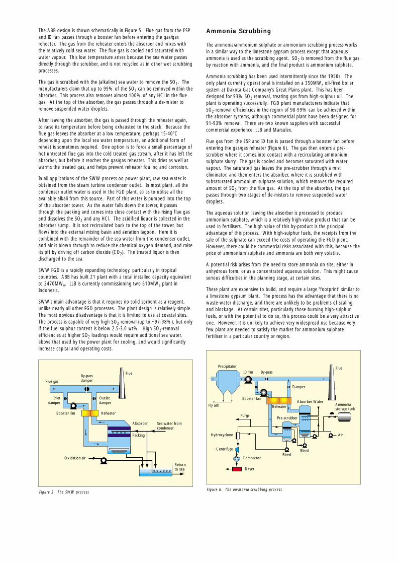
Ammonia Scrubbing
The ammonia/ammonium sulphate or ammonium scrubbing process worksin a similar way to the limestone gypsum process except that aqueousammonia is used as the scrubbing agent. SO2 is removed from the flue gasby reaction with ammonia, and the final product is ammonium sulphate.
Ammonia scrubbing has been used intermittently since the 1950s. Theonly plant currently operational is installed on a 350MWe oil-fired boilersystem at Dakota Gas Company’s Great Plains plant. This has beendesigned for 93% SO2 removal, treating gas from high-sulphur oil. Theplant is operating successfully. FGD plant manufacturers indicate that SO2-removal efficiencies in the region of 98-99% can be achieved withinthe absorber systems, although commercial plant have been designed for91-93% removal. There are two known suppliers with successfulcommercial experience, LLB and Marsulex.
Flue gas from the ESP and ID fan is passed through a booster fan beforeentering the gas/gas reheater (Figure 6). The gas then enters a pre-scrubber where it comes into contact with a recirculating ammoniumsulphate slurry. The gas is cooled and becomes saturated with watervapour. The saturated gas leaves the pre-scrubber through a misteliminator, and then enters the absorber, where it is scrubbed withsubsaturated ammonium sulphate solution, which removes the requiredamount of SO2 from the flue gas. At the top of the absorber, the gaspasses through two stages of de-misters to remove suspended waterdroplets.
The aqueous solution leaving the absorber is processed to produceammonium sulphate, which is a relatively high-value product that can beused in fertilisers. The high value of this by-product is the principaladvantage of this process. With high-sulphur fuels, the receipts from thesale of the sulphate can exceed the costs of operating the FGD plant.However, there could be commercial risks associated with this, because theprice of ammonium sulphate and ammonia are both very volatile.
A potential risk arises from the need to store ammonia on site, either inanhydrous form, or as a concentrated aqueous solution. This might causeserious difficulties in the planning stage, at certain sites.
These plant are expensive to build, and require a large ‘footprint’ similar toa limestone gypsum plant. The process has the advantage that there is nowaste-water discharge, and there are unlikely to be problems of scalingand blockage. At certain sites, particularly those burning high-sulphurfuels, or with the potential to do so, this process could be a very attractiveone. However, it is unlikely to achieve very widespread use because veryfew plant are needed to satisfy the market for ammonium sulphatefertiliser in a particular country or region.
v v v
Return to sea
Packing
FlueBy-passdamperFlue gas
Inletdamper
Booster fan
Oxidation air
Reheater
Outlet damper
Absorber Sea water fromcondenser
v v v
v v v v
Figure 5. The SWW process
Booster fan
ID fan
Reheater
Purge
BleedBleed
Pre-scrubber
Absorber Water
Flue
Ammonia storage tank
Damper
Compactor
Dryer
By-pass
Precipitator
Fly ash
Hydrocyclone
Centrifuge
Air
v vv
v vvv vv
Figure 6. The ammonia scrubbing process
1751 TSR 012 31/5/00 3:59 pm Page 4

The Wel lman-Lord Process
The Wellman-Lord Process is regenerative, ie the active reagent used forremoval of SO2 from the flue gas is regenerated in a second process stage,and returned to the first stage (absorber tower) for re-use. Consequently,the process does not involve the large-scale consumption of lime orlimestone, unlike other processes described here.
The process involves the wet scrubbing of SO2 from the flue gas withaqueous sodium sulphite solution. It produces a saleable by-product that,depending on the plant’s design, could be elemental sulphur, sulphuricacid or liquid SO2.
The Wellman-Lord process has been installed on nearly 40 plant, in Japan,the USA and Germany. This includes over 3000MWe of electric utilityboilers, and many industrial plant. However, there appears to have beenno new plant built in recent years.
Flue gas from the ESP and ID fan is passed through a booster fan beforeentering the gas/gas reheater (Figure 7). Here the gas is cooled as heat isextracted. The warm gas from the reheater enters the pre-scrubber/absorberand mixes with the process liquor. An equilibrium temperature isestablished, when the flue gas becomes saturated with water vapour.
In the pre-scrubbing stage, fly ash and HCl are removed. In the mainabsorber, the gas is scrubbed with the process liquor, to remove therequired amount of SO2. Typically 95-98% of the SO2 can be removedwithin the absorber. At the top of the absorber, the gas passes throughde-misters to remove suspended water droplets. After leaving the
absorber, the gas is passed through the reheater again, to raise itstemperature before being exhausted to the stack.
A pre-scrubber is usually fitted upstream of the absorber, primarily toremove any HCl present in the flue gas. If HCl were to dissolve in themain absorber liquor, the concentration of sodium chloride in the liquorwould progressively increase to levels where it would interfere with thechemistry governing the removal of SO2. The degree of desulphurisationattained would hence progressively fall off.
In the main absorber, the flue gas is scrubbed with aqueous sodiumsulphite solution, forming sodium bisulphite. The sodium bisulphite isdecomposed by steam heating in an evaporative crystalliser to producesodium sulphite and SO2. The sodium sulphite is returned to the flue gasabsorber tower circuit for re-use, while the concentrated SO2 gas streamcan then be treated as appropriate to produce a by-product suitable forexport. Whether this is concentrated SO2 liquid, sulphuric acid orelemental sulphur would depend on the local commercial environment.
This process can achieve a SO2-removal efficiency of well over 95% onhigh-sulphur fuels. It is expensive to install but relatively cheap to operateand, as such, in relation to other processes, is best suited to high SO2-removal requirements, high-sulphur fuel, and plant with a long residuallife. Comparative studies have suggested that the operating cost is verysimilar to that of the limestone gypsum process.
The process also has the advantages that it does not require theconsumption of large quantities of sorbent and does not produce largequantities of solid waste.
Sulphatesolids
Booster fan
ID fan
Reheater
Absorber
Regenerated LiquorTankTank
Condenser
Damper
By-passPrecipitator
Fly ash
Sodium carbonate/hydroxide
Sodium carbonate or hydroxide make-up
Blowdown
EDTAWater
v vvv vv
v vv
Flue
Figure 7. The Wellman-Lord process
Blower
Blower
Blower
Hydrator
Lime storage silo
Recycle
Water
Lime feed bin
Dry productfor disposal
Disposal silo
New FF or ESPCFB reactor
From boiler air heater
ID fan
VLime reception system
Figure 8. The CFB process
1751 TSR 012 31/5/00 3:59 pm Page 5

Circulat ing F luidised Bed (CFB)
In the CFB process, the flue gas is passed through a dense mixture of lime(calcium hydroxide), reaction products and sometimes fly ash, whichremoves the SO2, SO3 and HCl. The final product is a dry powderedmixture of calcium compounds.
The process has been commercially available for over 10 years, and is anexpanding technology, particularly for retrofitting to small- to medium-sized power plant. Because of its simplicity, higher performance, lowerspatial requirement, and sometimes lower cost, it is nowadays beingchosen instead of the more widely established spray dry process in certainapplications. The process and variants on it are now supplied by severalvendors, whose designs vary significantly, although the process chemistriesare the same. The originator and most experienced vendor is LLB.
Flue gas from the airheater (Figure 8) is carried through the inlet venturithroat of the CFB reactor and passes upwards through a fluidised bed oflime, reaction products and fly ash particles contained within the verticalreactor tower. This removes up to 99% of the SO2 and all of the SO3 andHCl from the flue gas. From here the gas is carried through the dustarrestor and the ID fan to the stack.
A large quantity of the particulate matter in the CFB reactor is carried withthe flue gas into the ESP or fabric filter (FF) located downstream. Most ofthe solids collected in the pre-collector and ESP are returned to the reactor,so as to achieve a high dust loading within the fluidised bed.
The normal sorbent is quicklime, which is hydrated on site to make calciumhydroxide powder (hydrated lime). This is injected into the base of thereactor. Water is also added to humidify the flue gas and so improve SO2and particulate removal. The water flow is controlled to achieve atemperature ~20ºC above the adiabatic saturation temperature of the gas.The solid by-product from the process, including fly ash, is transportedfrom the bottom of the ESP to a silo, prior to dispatch from site.
CFB FGD plant have been fitted to a total of over 3000MWe of powerplant, as well as units fitted to a variety of industrial processes (such ashydrogen fluoride removal), at sizes of up to 300MWe. Major suppliers ofthe technology are LLB (Germany), Wulff (Germany), FLS Miljø of Denmark(gas suspension absorber (GSA) process) and ABB (new integrateddesulphurisation (NID) technology).
The CFB process is capable of very high SO2-removal efficiency, even withvery high inlet SO2 concentrations. For example, one German plantachieved 97% SO2 removal with an inlet SO2 concentration of 13,000mgNm-3. Several CFB/GSA plant have achieved >99% SO2 removal. Theprocess can also achieve complete removal of SO3.
This is a well-established FGD process with rapidly growing experience. Itis cheaper to install than a limestone gypsum plant and costs about thesame as a spray-dry plant. It has a much lower space requirement than alimestone gypsum plant, at least as high SO2-removal efficiency, and iscapable of complete removal of SO3. It has almost unlimited turndowncapability and accommodates very rapid changes in inlet SO2concentration. Also, it does not normally suffer from serious scaling,plugging or corrosion problems. However, it can be relatively expensive tooperate and, in common with all other semi-dry processes, it generates awaste product that normally has to be disposed of.
Spray-dry Process
In the spray-dry process, concentrated lime (calcium hydroxide) slurry isinjected into the flue gas, to react with and remove acidic compounds such asSO2, SO3 and HCl. The final product is a dry powdered mixture of calciumcompounds. The spray-dry process is supplied by several vendors, whosedesigns vary significantly - although the process chemistries are the same.
The flue gas from the air heater is carried into the spray-dryer vessel, whereit comes into contact with a finely atomised spray of lime and by-productslurry, delivered from a single high-speed rotary atomiser (Figure 9). Thisremoves up to ~95% of the SO2 and most if not all of the SO3 and HClfrom the flue gas. From here the gas is carried through the dust arrestorand the ID fan before discharge through the stack.
The normal sorbent fed to this process is quicklime. This is slaked on site,with excess water, to produce a calcium hydroxide slurry (slaked lime).This is mixed with recycled by-product before being pumped to the rotary
atomiser. The water in the slurry will humidify the flue gas and so improveboth SO2 and particulate removal. The water flow rate is controlled so asto achieve a temperature approximately 20ºC above the adiabaticsaturation temperature of the gas. When firing bituminous coal, thehumidified gas temperature would be ~70ºC.
The solid by-product from the process, including fly ash, is transportedfrom the bottom of the ESP to a silo, prior to dispatch from site.
As with other semi-dry systems producing a throw-away by-product, thespray-dry process is relatively cheap to install, typically being ~70% of thecost of the equivalent limestone gypsum system. However, the variableoperating costs are among the highest of the major FGD processes, due toboth the high lime usage and the costs of by-product disposal. The lowersorbent utilisation of the spray-dry process, compared with the CFB, meansthat additional costs are incurred twice: extra lime has to be bought andthen a portion of this is dumped at a cost.
The spray-dry process is one of the most well-developed and widely usedworldwide. The total installed capacity is in excess of 15,000MWe. Thetechnology is well understood, and offered by a number of contractors.The process is very similar in many respects to the CFB process and thetwo are in competition. The process can achieve 85-90% SO2 removalwith moderately high-sulphur fuels.
The spray-dry process is cheaper to install than a limestone gypsum plant,and similar to or slightly more expensive than a CFB-type plant. However,like the CFB it can be relatively expensive to operate, depending on therelative costs of labour, power, lime and limestone. The disposal cost ofthe residues produced also adds to the overall operating cost.
The Duct Spray-dry Process
This process is essentially the same as conventional spray-drying, exceptthat in this case the spray-dryer vessel is omitted, and the lime slurry issprayed directly into the duct. The lime reacts with and removes the acidgases. The final product is a dry powdered mixture of calcium compounds.
The process has been developed by two suppliers, but has not yet reachedfull-scale continuous commercial operation. It is one of a number of FGDprocesses developed or being developed primarily for those instances inwhich a moderate degree of desulphurisation (50-75%) is required onplant with limited operating hours and remaining lifetimes.
Furnace Sorbent Inject ion
This is another process developed for moderate degrees ofdesulphurisation with low capital costs. The process involves the injectionof hydrated lime into the furnace cavity of the boiler to absorb SO2. Spentsorbent is extracted with the fly ash, in an ESP or FF. The final product is amixture of ash and calcium compounds.
This process was first investigated in the 1950s and a second phase hasbeen under way since the 1970s. However, there are very few plant nowin commercial operation, most being in Poland. Dry hydrated lime is
BlowerBlower Slaker
Lime slurryfeed tank
Lime storage silo Water
Disposalsilo
Flue
Lime feed bin
Lime reception system
Blower
ESP or FFSpray-dryer
From boiler air heater
ID fan
V
Figure 9. The spray-dry FGD process
1751 TSR 012 31/5/00 3:59 pm Page 6

blown pneumatically into the furnace, typically above the burners (Figure10). This removes up to ~70% of the SO2 from the flue gas. From theboiler, the gas is carried through the air heater, dust arrestor and ID fanbefore discharge through the stack.
It is one of the cheapest FGD processes to install but can be expensive tooperate because it is inefficient in its use of sorbent. Because of this,furnace sorbent injection is most suitable for retrofit situations. It is wellsuited to a situation where only a low SO2-removal efficiency is required,and where there is little space available in the unit plant area. The fly ashcan not be collected separately from the spent sorbent. Consequently allthe furnace ash as well as the solid by-product mixture must be dumped.
The Sodium Bicarbonate Inject ion Process
This process involves the direct injection of dry sodium bicarbonate intothe flue gas duct downstream of the airheater, to react with and removeacidic compounds such as SO2, SO3 and HCl. The final product is a drypowdered mixture of sodium compounds and fly ash. It is suitableprimarily for those applications where a moderate degree ofdesulphurisation is required at low capital cost, although it should benoted that the reagent itself, sodium bicarbonate, is relatively expensive.
Sodium bicarbonate is pneumatically injected into the flue gas stream as adry fine powder. This removes up to ~70% of the SO2 from the flue gas.SO3 and HCl are removed to some extent. From here the gas is carriedthrough the dust arrestor and the ID fan before discharge through thestack. All of the particulate matter from the process and the fly ash arecarried with the flue gas into the dust arrestor – an ESP or FF.
The process has been demonstrated on four full-scale, coal-fired boilers of80-575MWe in the USA. It has also been demonstrated on a 120MWeboiler in the UK by PowerGen.
Combined SOx/NOx Removal Systems
Both SO2 and oxides of nitrogen (NOx) are present in flue gases. Sinceemissions of both are regulated, it would, in principle, be highly desirableto remove both using the same process. However, despite the fact thatboth are acidic (and therefore amenable to reaction with a range ofalkaline substances), in practice, separate methods are normally used forthe control of each: conventional FGD processes are used to restrict SO2emissions and NOx are limited either by combustion measures or selectivecatalytic reduction (SCR). One reason for this is that any combinedSOx/NOx-removal system would have to be sufficiently effective atremoving both species that no further system was required.
Several combined SOx/NOx-removal systems have, however, beendeveloped to the point where they are suitable for deployment on utility-scale boilers. One of the most advanced of these is the SNOX process(Figure 11).
The SNOX process has been developed by the Danish company HaldorTopsøe. The process is located downstream of the particulate controldevice. The flue gas is reheated and then undergoes SCR. The flue gas isthen further heated and a second catalytic reactor oxidises SO2 to SO3.The gas is then cooled to condense out the SO3 as sulphuric acid. Thecondenser uses glass tubes to prevent excessive acid corrosion.
A further point about the process is that, since both the oxidation of SO2to SO3 and the reaction of water vapour with SO3 to form sulphuric acidare exothermic, for high-sulphur coals (ie >~2.5%) the heat released issufficient to offset the auxiliary power consumption. The process uses noreagents other than ammonia and produces sulphuric acid of saleablequality.
Large SNOX units have been built on plant in Denmark, Italy and the USA,with smaller units in Japan, the Czech Republic, Italy and Denmark. A SNOXunit has been operational on Unit 2 (305MWe) of Elsam’s Nordjyllansværket
Stack
Coolingair
Supportburner
Acidcollector
Acid storagetank
Catalytic SO2reactor
Catalytic NOxreactor
Ammonia
Hot air
Natural gas
Clean flue gas
Hot air discharge
Electrostaticprecipitator
To disposal
Sulphuric acid
Condenser (WSA Tower)
Baghouse
Ash to disposal
Ash
Boiler
Air preheater
Flue gas
Flue gas heater
Fluegas
Air
Coal
Supportburner
Supportburner
Figure 11. The SNOX process for the combined removal of NOx and SOx (From the USDOE Website)
BlowerBlower Hydrator
Lime feed bin
V
Lime reception system
Disposalsilo
Air compressor Dry productfor disposal
Flue
Blower
Water
ESP
Boiler
ID fan
Water forhumidification
Figure 10. FGD using furnace sorbent injection
1751 TSR 012 31/5/00 3:59 pm Page 7

in Denmark since 1991. SNOX has also been installed in the USA under theUnited States Department of Energy’s (USDOE’s) Clean Coal TechnologyDemonstration Program. A small unit was installed on a slip-stream (35MWeequivalent) of Unit 2 at Ohio Edison’s Niles station in Ohio.
F G D C O S T SCosts of FGD plant are very site-specific. The capital costs of FGD plantare difficult to accurately assess as they are considerably influenced bymarket conditions and other factors, eg geographical location and theamount of preparatory site work required. Running costs depend on thecosts of sorbents, the costs associated with disposal of the by-productsand power costs, all of which are influenced by local conditions.
Capital Costs
Bid costs of FGD plant depend on market conditions and other commercialfactors. Such costs are seldom disclosed. In addition, the cost of the FGDplant obviously depends on technical factors, eg:
• volume of flue gas to be treated
• concentration of SO2 in the flue gas
• degree of desulphurisation required
• quality of the by-products produced
• other environmental constraints, eg permitted waste water discharges
• the need or otherwise for flue gas reheat
• the degree of reliability and redundancy required
• design life.
Capital costs of FGD plant have been falling in real terms over many years.This is partly due to improvements in design and also partly due to lessredundancy as suppliers become more knowledgeable about the abilities ofthe technology. For example, many early FGD units had multiple and/orspare absorber towers – this is now seldom the case. The downward trendin FGD costs is shown schematically in Figure 12. Current costs of FGDplant are roughly in the range $100-125 kW-1 (£65-80 kW-1), with furtherfalls in cost anticipated in 2000 and beyond.
Differences in the capital costs of different FGD processes are determinedby the degree of complexity of the process, the amount of engineeringrequired and other factors. FGD processes in which the sorbent isprocessed to give a saleable by-product (eg limestone gypsum, ammoniascrubbing) or in which the sorbent is regenerable (eg Wellman-Lord) havehigher capital costs than other processes (see Figure 13).
Operat ing Costs
Operating Costs can be split into variable and fixed costs.
Variable costs cover such aspects of operation as reagents, by-productdisposal and utilities (steam, power, water etc). Reagent costs will beapproximately proportional to the amount of SO2 removed, although theywill also be influenced by the chemical stoichiometry, which may vary asthe degree of desulphurisation changes. Similarly, by-product disposalcosts will be proportional to the amount of by-product produced (and willbe negative if the by-product can be sold). Costs of steam, power, wateretc will be determined both by the amount of flue gas processed and bythe throughput of reagents and by-products.
Reagent and by-product costs can be considerably influenced by thelocation of the plant. The total cost of a reagent to the plant will includea transport cost, and so the proximity (or otherwise) of a suitablelimestone mine, for example, can be an important consideration. Similarly,the economics of an FGD process benefit from the proximity of aconvenient disposal point for the by-products; eg the limestone/gypsumFGD plant at Ratcliffe-on-Soar Power Station benefits from having a majoruser of gypsum located nearby.
Indicative relative variable running costs for several FGD processes areshown in Figure 14.
In general, those processes that produce a saleable by-product, such asgypsum (limestone gypsum) or ammonium sulphate (ammonia scrubbing),have lower nett operating costs than those processes that produce a non-saleable by-product that incurs disposal costs. Actual variable operatingcosts can depend critically on the actual market conditions for sorbents, by-products, disposal costs etc, and these can be very location-specific. As ageneral guide, variable operating costs can be in the order of £2 per MWh.
Inst
alle
d co
st (
$ kW
-1)
500
400
300
200
100
01970 1980 1990
Year
1997 2000
Figure 12. Reductions in the cost of retrofit FGD units in the USA (After Broward &
Brinkmann)
Reagent handling
Flue gas handling
General & additional equipment
SO2 removal
By-product handling
Engineering & contingency
Ammoniascrubbing
CFB
Tota
l pla
nt c
ost
Lime spray-dry
LimestoneGypsum
Wellman-Lord
Figure 13. Indicative relative costs of FGD processes (After EPRI, 1992)
Ammoniascrubbing
CFB
Vari
able
cos
ts
Lime spray-dry
LimestoneGypsum
Wellman-Lord
Reagents Utilities By-products
Figure 14. Indicative relative variable operating costs (After EPRI, 1992)
1751 TSR 012 31/5/00 3:59 pm Page 8

Fixed costs cover such aspects as operating labour, maintenance (bothmaterials and labour) and administration.
Maintenance costs are usually correlated or estimated as a percentage ofthe total plant cost. The actual percentage of plant cost depends on thetype of unit operation, with unit operations such as solids handling, orthose involving high temperatures or pressures, requiring moremaintenance than a process that involves liquids and gases at ambientconditions (see Figure 15).
Maintenance costs are usually taken to be independent of plant operatinghours or operating regime. In reality both these affect maintenance costs.The number of start-ups, in particular, can have a very significant effect onthe rate of degradation of plant components, due to the mechanical andthermal stresses that the start-up procedure imposes on the plant. Specificexamples include the effects of thermal cycling on the linings used in FGDabsorbers and the additional rotational loads on motors and pumps as theyare accelerated to operating speed. This, however, is still a relativelypoorly understood area.
F U T U R E M A R K E T S F O R F G DThe future market for FGD plant will be mostly, although not exclusively,for use with coal-fired power stations. This market can be divided intotwo classes: retrofits to existing units and FGD equipment for new units.The former will be more important for parts of the world such as WesternEurope, where there is unlikely to be any significant new build of coal-firedpower stations in the next 10 years. The latter will be more important forparts of the world such as India and China.
Other potential markets for FGD include: oil-fired boilers, sulphuric acidplant, cement kilns, other industrial boilers and oil refinery fluid catalyticcracking units (FCCUs).
A survey of potential markets for clean coal technologies, published by theInternational Energy Agency (IEA) in 1996, identified opportunities for FGDretrofits to existing coal-fired units. It also estimated the market for newpulverised fuel (pf)-fired units; since some or many of these new units willbe fitted with FGD as a matter of course, an overall estimate of the marketfor FGD plant, for coal-fired plant, can be made for the next decade.
The total market for FGD plant is likely to exceed £1Bn per year over thenext 10 years.
North America
A considerable fraction of the coal-fired capacity in Canada and the USAhas FGD (retro)fitted. However, there is significant scope for further FGDretrofits, as legislation governing air quality is being progressivelytightened. In addition, there will be some new build of coal-fired units.Although a substantial proportion of this build will be integratedgasification combined cycle (IGCC) or fluidised bed combustion (FBC) thatdo not require FGD, there will be some new pf-fired units that willcertainly require FGD. Overall, therefore, North America will continue tobe one of the major markets for FGD plant worldwide.
Europe
The two factors limiting the future market for FGD plant in WesternEurope are (i) a large proportion of coal-fired plant are already fitted withFGD, thus reducing the market for further retrofits, and (ii) the switch togas as the preferred fuel for power generation limits the amount of newcoal-fired capacity that will be built.
Overall, therefore, the market for FGD in Western Europe is in its maturephase, with the majority of units having already been (retro)fitted with FGD.
Parts of Eastern Europe and the Former Soviet Union (FSU) are verydependent on coal, not only for power generation but also for industrialand domestic use. Under Communist regimes, environmental protectionwas sacrificed to economic development and there was nodesulphurisation. In the last 10 years, FGD has been introduced into partsof Eastern Europe; however, this has been constrained by cost.
The countries in this region most dependent on coal are the CzechRepublic, Poland, Bulgaria, Russia and Ukraine. Nearly all of the coal-firedpower stations in the Czech Republic have now been retrofitted with FGD.The most important market for FGD in Eastern Europe at the moment isprobably Poland. Poland has ~28GWe of coal-fired plant; of this, 10GWehas been or is currently being retrofitted with FGD. Plans exist to retrofitmost of the main coal-fired power stations there. Bulgaria is anothercountry with significant coal-burning capacity; its indigenous lignite is veryhigh in both sulphur and ash, making Bulgarian power stations highlypolluting. As yet, only a very small proportion of its coal-fired plant hasbeen fitted with FGD. The major factor limiting the uptake of FGD is thecost. The same applies to both the Russian Federation and Ukraine, bothof which have very significant coal-fired generating capacity and coal-firedindustrial boilers.
South Asia
Both Pakistan and India rely heavily on thermal power plant for powersupply. India has a large number of coal-fired units burning indigenouscoals. These coals are generally high in ash but low in sulphur, and theemphasis on environmental control so far has been mostly on fitting orretrofitting ESPs to control particulate emissions. Very few Indian powerplant have FGD (one exception is the Tata-owned plant at Trombay nearMumbai, which uses SWW – Figure 17) and very few if any of the newcoal-fired plant have provision for FGD. Recent units commissioned inPakistan have been based on fluidised bed boilers. There will be somemarket for retrofit FGD and a larger market for FGD for new plant.
Cap
acity
in G
We
Wes
tern
Eur
ope
Cen
tral
& E
aste
rn E
urop
ean
d Fo
rmer
Sov
iet
Uni
on
Sout
h A
sia
Chi
na
East
Asi
a
Japa
n, A
ustr
alia
an
d N
ew Z
eala
nd
Afr
ica
Cen
tral
& S
outh
Am
eric
a
Nor
th A
mer
ica
Retrofits
50
45
40
35
30
25
20
15
10
5
0
New Units Total
Figure 16. Estimated total market for FGD for coal-fired power plant, 1996-2010
(After IEA)
Operations
CFB
Fixe
d co
st
Lime Spray-dry
Maintenance Admin & support
LimestoneGypsum
Ammoniascrubbing
Wellman-Lord
Figure 15. Comparative fixed operating and maintenance costs for FGD processes
1751 TSR 012 31/5/00 3:59 pm Page 9

China
Coal is China’s primary indigenous fuel source and is in widespread use forpower generation and for industrial and domestic purposes. Thewidespread use of coal on a significant scale with very few environmentalcontrols has resulted in China having significant pollution problems.China’s ninth Five Year Plan (1996-2000) is the first to addressenvironmental protection, and includes provision to reduce emissions fromthe coal and oil industries.
FGD plant was introduced into China in the early 1990s (Figure 18). Sofar, very few plant have been built, and the emphasis has been on tryingone of each type in an attempt to determine which are the most suitabletechnologies for China. Many of the plant so far built have beensupported by the World Bank.
The massive increase in electrical generating capacity required to keep pacewith increasing power demand means that the emphasis for FGD will be onnew units rather than retrofits. However, it should be noted that mostcurrent coal-fired independent power projects (IPPs) in China lack FGD.
Japan, Austral ia and New Zealand
These three developed countries of the Pacific Rim vary in terms ofelectricity generation. Coal plays a very minor role in the generation ofpower in New Zealand. Australia, particularly the eastern part, dependsheavily on coal for power generation. Australian coal is relatively low insulphur, thus sulphur emissions have not hitherto been a major issue andnone of the major coal-burning stations is fitted with FGD. Japangenerates power mostly from gas, oil and nuclear. Its coal-fired units areall equipped with FGD. The absolute amount of power generated fromcoal is set to rise as older oil-fired units are replaced, and these new coal-fired units will require FGD, although a significant proportion of new coal-fired units in Japan may well employ pressurised fluidised bed combustion(PFBC).
East Asia
Many of the countries in this region have recently undergone (SouthKorea) or are currently undergoing (eg Malaysia, Indonesia) rapid economicexpansion with a consequent increase in power demand. However,economic growth in many of these countries has recently, albeittemporarily, stalled.
It is anticipated that much of the new generating capacity will be coal-fired. Environmental problems resulting from the use of coal have alreadybeen significant in some areas and some of the countries in this regionhave already installed FGD.
Figure 17. SWW FGD plant at Tata Electric’s Trombay plant, India (Courtesy of ABB
Alstom Power)
Figure 19. LLB SWW plant at Paiton, Indonesia (Courtesy of LLB)
Figure 18. Luohuang FGD plant under construction in China (Courtesy MHI)
1751 TSR 012 31/5/00 3:59 pm Page 10

Central and South America
Coal plays only a very minor role in power generation in Central and SouthAmerica. The market for FGD for new and retrofit units is unlikely toexceed 1GWe in the next 10 years.
Africa
Coal is the predominant source of power in South Africa and in someneighbouring states. The IEA forecasts that there could be 4GWe of FGDretrofitted to existing plant; in addition, a further 4GWe of FGD could berequired for new units.
N E W D E V E L O P M E N T SImprovements to Exist ing Processes
Work is ongoing in a number of fields to improve currently-existing FGDprocesses. Much of the work is focused on limestone/gypsum and otherwet scrubbing processes, since these represent the most common typeworldwide. Specific areas of improvement include higher desulphurisationefficiencies, lower capital and operating costs and better reliability.
One of the most noticeable developments is in the scale-up in absorbersize. At one time, it was not uncommon to have multiple scrubbers forone boiler, partly for redundancy reasons. Experience with larger FGDunits, and confidence in the high reliability of FGD plant, has givensuppliers the confidence to move firstly to single absorbers for even thelargest units (up to 1000MWe) and, recently, to install one FGD unitserving two large (~400MWe) boilers. Scaling-up plant size in this wayconsiderably reduces the overall capital costs, since one absorber is usuallycheaper than two of half the throughput: the amount of steel etc used ismuch less and fabrication procedures are also reduced.
Costs have also been reduced by increases in the gas velocity, and thusflowrate, through the absorber. This results in a smaller (and thus cheaper)absorber for the same gas flow. Until recently, a design velocity of ~3m s-1
was usual; however, velocities of ~4m s-1 are now being adopted and4.5m s-1 is considered possible. Reductions in tower height are also beinginvestigated, as the processes in the scrubber and sump are betterunderstood and this allows scrubbers to be designed with shorter gas andparticle residence times.
Aerodynamic modelling and computational fluid dynamics (CFD)simulations of the gas and liquid flows in absorbers are proving invaluablein ensuring better gas/liquid contact and increased rates of mass transfer.This aids the development of better nozzle and contacter designs and misteliminators. A further improvement to the limestone gypsum process isthe use of higher-concentration limestone slurries. This gives better masstransfer and also reduces running costs, as the amount of liquid or slurryto be pumped is reduced.
There have been important developments in the major plant componentsthroughout the last 30 years, in parallel with the process developments.These include larger booster fans and a move towards axial rather thancentrifugal designs. These require far less power at reduced boiler loads.The development of larger and more efficient fans will be advantageous tothe development and acceptance of very large absorbers. Gas/gasexchangers are another area of work, with the use of liquid-coupledheaters (or other low-leakage exchangers) reducing the amount of gasleakage between the clean and raw gas sides of the flue gas path.
Further development of corrosion-resistant materials continues. Someslightly improved or lower cost alloys have come onto the market, and avinyl ester resin with mica rather than glass flakes has been developed,which will withstand slightly higher flue gas temperatures. Glassreinforced fibre (GRP) pipe sizes have increased to the point where they arenow used for the manufacture of small absorbers, up to ~80MWeequivalent or larger in size. Further use of (larger) GRP scrubbers can beexpected, in many cases offering lower costs, with better corrosion andweather resistance and easier maintenance than for metal absorbers.
One area where there is a need for improved materials is in FGD recyclepumps. Under certain operating conditions these can have a relativelyshort life. Rubber internals can suffer damage through contact with solids,and metal casings and impellers can suffer corrosion and cracking,particularly in high-chloride environments.
As FGD plant designs have improved and environmental standards havebecome more onerous, there has been a need to upgrade the performanceof older and less well-designed plant. Many of the leading suppliers havebeen involved in this already, eg fitting trays or improved spray headerarrangements, improved nozzles, or better packing. There will be a steadydemand for this type of improvement of older plant in the future,including such recent innovations as double open-ended hollow conenozzles, to provide co-current scrubbing, as well as increased limestoneloading, finer grinds and/or organic additives.
New Processes
Processes are under development in which the flue gas is irradiated withelectron beams in order to convert the SOx (and NOx) into more reactivespecies that can be removed from the flue gas more easily. Most variantsof this process combine the process with the injection of ammonia for NOxcontrol. High-energy electrons react with molecules in the flue gas toproduce radicals that then react with the SOx and NOx in the flue gas toproduce sulphuric and nitric acids that in turn react with ammonia or someother alkali.
Research on electron beam processes was started in Japan in 1970, butthey are only now reaching the point of commercial-scale demonstration.One of the most advanced of the processes under development is that ofthe EBARA Corporation (Figure 21). Flue gas from the ESPs is cooled andenters the process vessel in which ammonia is added and the gas irradiatedwith electrons. Ammonium sulphate and nitrate are formed and are carriedin the gas as an aerosol. The ammonium salts are removed downstream ofthe reaction vessel using a further ESP, and the salts are recovered and soldas fertiliser. The process has recently been tested at the 90MWe scale onthe Chengdu Power Station belonging to the Sichuan Electric PowerCompany; 80% SOx and 20% NOx reductions were achieved.
Considerable research effort has been expended on the development ofdry sorbent-based FGD systems that are also capable of removing NOx. Upto 90% NOx reduction has been achieved in some pilot-scale reactors.MHI and Hokkaido Electric have been jointly developing the LILAC (livelyintensified lime ash compound) process. The reagent is a mixture of lime,
Figure 20. GSA absorber (Courtesy of FLS Miljø)
1751 TSR 012 31/5/00 3:59 pm Page 11

fly ash and spent sorbent (or gypsum). It is claimed that this is madehighly reactive towards SO2 and NOx through curing with hot water. Thereagent can be sprayed into the flue gas as a slurry or as a dry powder,and can be used with a spray drier, or injected directly into the flue gasduct. This process is still at the development/demonstration stage. It hasrecently been retrofitted to the Huangdao Power Station in China.
A combined SOx/NOx system using regenerable copper oxide adsorbent isunder development in the USA, named COBRA (copper oxide bedregenerable application). In the process a copper oxide sorbent is used toremove SO2 in a moving-bed adsorber. The copper oxide is converted tocopper sulphate and also acts as a catalyst for the reduction of NOx tonitrogen using ammonia. The sorbent is regenerated using methane andthe SO2 liberated is processed to give elemental sulphur or sulphuric acid.Tests on the 1MWth scale have shown desulphurisation of >98%.
R&D Needs
Key requirements for FGD systems and plant are:
• high SO2 removal
• high reliability
• low auxiliary power consumption
• use of a single absorber (where applicable)
• saleable or usable by-product.
R&D work required to support these requirements can be split into process,component and materials development.
Process improvement entails such R&D aspects as better understanding ofthe flow regimes in absorbers and the nature of the mass transferphenomena in both wet and semi-dry processes. In addition, the moreonerous operating regimes that FGD plant are now operating under meanthat work needs to be undertaken to understand the long-term effects ofplant cycling and of repeated start-ups and shut-downs, and the optimumcondition in which to leave FGD plant standing idle. Work is also requiredon the utilisation of semi-dry process by-products.
The UK has a particular strength in the supply of components for FGDplant, particularly gas/gas reheaters, fans, pumps and gypsum de-wateringequipment. Most gas/gas reheaters currently installed on FGD plant are ofthe rotary regenerative type. These generally perform well, but they canbe susceptible to corrosion and inevitably there is a degree of gas leakage,with untreated sour gas crossing over to the clean gas side, reducing theSOx removal of the overall process. There is thus a need for thedevelopment of improved designs with greater corrosion resistance andbetter sealing.
Gypsum slurry and recycle pumps are widely used in FGD plant but cansuffer from corrosion (if not rubber-lined) or erosion (if rubber-lined).Increased corrosion/erosion resistance will reduce FGD plant downtime andmaintenance costs. Gypsum de-watering is undertaken using basketcentrifuges or vacuum belt filters. Large FGD plant typically require a
dozen or more centrifuges, which can represent a considerable expense;scale-up of the technology could reduce costs. Furthermore, centrifugeswork on a cyclic basis, with rapid acceleration and deceleration that putshigh stresses on the equipment. An alternative, the decanter centrifuge,has so far found only very limited application on FGD plant butdevelopment work to improve its de-watering efficiency could reduce bothcapital and maintenance costs. The further development of steam-heatedvacuum belt filters capable of high levels of de-watering would also beadvantageous.
Materials development is required to underpin the work on componentimprovement outlined above. In addition, the application of metals,organic linings and GRP for FGD absorbers, could reduce costs, andimprove operational flexibility and reliability.
C O N C L U S I O N S• A wide variety of FGD technologies are available. The most widely used
processes are the limestone/gypsum (and its variations) and the spraydry process, but newer technologies such as CFB and SWW are rapidlygaining acceptance.
• Overall, there is ~275GWe of FGD plant currently installed worldwide.
• A steady improvement in process design over the years means thatmodern designs can achieve 95%+ sulphur removal.
• At the same time, costs have fallen steadily and are now equivalent to$100-125 kW-1 (~£65-80 kW-1).
• Most FGD plant currently operational are in North America, WesternEurope and Japan. FGD technology is rapidly being deployed in parts ofEastern Europe, East Asia and South East Asia, and there could be majormarket opportunities in China and India.
• Several new processes are under development, many of which aredesigned to remove both SOx and NOx.
• At the same time, further improvements are being made to absorberdesign and to plant components such as heaters and fans.
B I B L I O G R A P H Y• Boward, W L and Brinkmann, M S (1998) ‘Retrofit FGD System Price
Trends and Influence Factors’, Proceedings of the 60th American PowerConference, 14–16 April 1998, Chicago
• EPRI (1992) ‘Economic Evaluation of Flue Gas Desulfurisation (FGD)Systems’, EPRI GS-7192, vols 1 and 2
• IEA/OECD (1996) ‘Clean Coal Technology: Markets and Opportunities to 2010’
• Singer, J G (1991) ‘Combustion Fossil Power – A Reference Book on FuelBurning and Steam Generation’, Edited by J G Singer. Fourth Edition.Published by Combustion Engineering Inc. ABB Windsor Connecticut.ISBN 0-9605974-0-9
• Takeshita, M and Soud, H (1993) ‘FGD Performance and Experience onCoal Fired Plants’, IEACR/58, IEA Coal Research, London, July 1993.
Spray cooler
Ammonia
Water
Flue gas from ESPs
E-beam system
Clean flue gasto stack
ESP
Ammonium sulphate/nitratefertiliser to agglomerator
Process vessel
��
Figure 21. The EBARA process
1751 TSR 012 31/5/00 3:59 pm Page 12

Department of Trade and Industry
DTI/Pub URN 00/652
1751 TSR 012 31/5/00 3:59 pm Page 13


![Conference Paper - PowerGen-Middle East 2008[1]](https://img.dokumen.tips/doc/110x75/577d35701a28ab3a6b906b92/conference-paper-powergen-middle-east-20081.jpg)